EP3279971A1 - End plate of battery module and battery module - Google Patents
End plate of battery module and battery module Download PDFInfo
- Publication number
- EP3279971A1 EP3279971A1 EP17181356.1A EP17181356A EP3279971A1 EP 3279971 A1 EP3279971 A1 EP 3279971A1 EP 17181356 A EP17181356 A EP 17181356A EP 3279971 A1 EP3279971 A1 EP 3279971A1
- Authority
- EP
- European Patent Office
- Prior art keywords
- end plate
- plate
- battery module
- panel
- elastic member
- Prior art date
- Legal status (The legal status is an assumption and is not a legal conclusion. Google has not performed a legal analysis and makes no representation as to the accuracy of the status listed.)
- Granted
Links
- 238000005452 bending Methods 0.000 claims description 20
- 229920005989 resin Polymers 0.000 claims description 19
- 239000011347 resin Substances 0.000 claims description 19
- 239000000853 adhesive Substances 0.000 claims description 16
- 230000001070 adhesive effect Effects 0.000 claims description 16
- 238000000034 method Methods 0.000 abstract description 3
- 238000004519 manufacturing process Methods 0.000 abstract description 2
- 239000006260 foam Substances 0.000 description 7
- 229920000049 Carbon (fiber) Polymers 0.000 description 6
- 239000004917 carbon fiber Substances 0.000 description 6
- VNWKTOKETHGBQD-UHFFFAOYSA-N methane Chemical compound C VNWKTOKETHGBQD-UHFFFAOYSA-N 0.000 description 6
- 239000004744 fabric Substances 0.000 description 4
- 239000011152 fibreglass Substances 0.000 description 4
- 239000000463 material Substances 0.000 description 4
- 238000004026 adhesive bonding Methods 0.000 description 3
- 230000000694 effects Effects 0.000 description 3
- 229920001971 elastomer Polymers 0.000 description 3
- 239000003822 epoxy resin Substances 0.000 description 3
- -1 for example Substances 0.000 description 3
- 239000002184 metal Substances 0.000 description 3
- 229920000647 polyepoxide Polymers 0.000 description 3
- KXGFMDJXCMQABM-UHFFFAOYSA-N 2-methoxy-6-methylphenol Chemical compound [CH]OC1=CC=CC([CH])=C1O KXGFMDJXCMQABM-UHFFFAOYSA-N 0.000 description 2
- 239000004593 Epoxy Substances 0.000 description 2
- 229920005830 Polyurethane Foam Polymers 0.000 description 2
- 239000002131 composite material Substances 0.000 description 2
- 239000005007 epoxy-phenolic resin Substances 0.000 description 2
- 239000011521 glass Substances 0.000 description 2
- 239000007791 liquid phase Substances 0.000 description 2
- 229920001568 phenolic resin Polymers 0.000 description 2
- 229920001225 polyester resin Polymers 0.000 description 2
- 239000004645 polyester resin Substances 0.000 description 2
- 229920000139 polyethylene terephthalate Polymers 0.000 description 2
- 239000005020 polyethylene terephthalate Substances 0.000 description 2
- 229920007790 polymethacrylimide foam Polymers 0.000 description 2
- 229920000915 polyvinyl chloride Polymers 0.000 description 2
- 239000004800 polyvinyl chloride Substances 0.000 description 2
- 239000002356 single layer Substances 0.000 description 2
- 238000001721 transfer moulding Methods 0.000 description 2
- 229920006337 unsaturated polyester resin Polymers 0.000 description 2
- 125000000391 vinyl group Chemical group [H]C([*])=C([H])[H] 0.000 description 2
- 229920002554 vinyl polymer Polymers 0.000 description 2
- 239000003522 acrylic cement Substances 0.000 description 1
- 230000009286 beneficial effect Effects 0.000 description 1
- 230000003139 buffering effect Effects 0.000 description 1
- 230000006835 compression Effects 0.000 description 1
- 238000007906 compression Methods 0.000 description 1
- 230000005489 elastic deformation Effects 0.000 description 1
- 239000013013 elastic material Substances 0.000 description 1
- 230000014509 gene expression Effects 0.000 description 1
- 238000012986 modification Methods 0.000 description 1
- 230000004048 modification Effects 0.000 description 1
- 238000000465 moulding Methods 0.000 description 1
- 239000004814 polyurethane Substances 0.000 description 1
- 229920002635 polyurethane Polymers 0.000 description 1
- 239000011496 polyurethane foam Substances 0.000 description 1
- 230000002441 reversible effect Effects 0.000 description 1
- 239000007790 solid phase Substances 0.000 description 1
Images

Classifications
-
- H—ELECTRICITY
- H01—ELECTRIC ELEMENTS
- H01M—PROCESSES OR MEANS, e.g. BATTERIES, FOR THE DIRECT CONVERSION OF CHEMICAL ENERGY INTO ELECTRICAL ENERGY
- H01M50/00—Constructional details or processes of manufacture of the non-active parts of electrochemical cells other than fuel cells, e.g. hybrid cells
- H01M50/20—Mountings; Secondary casings or frames; Racks, modules or packs; Suspension devices; Shock absorbers; Transport or carrying devices; Holders
- H01M50/233—Mountings; Secondary casings or frames; Racks, modules or packs; Suspension devices; Shock absorbers; Transport or carrying devices; Holders characterised by physical properties of casings or racks, e.g. dimensions
- H01M50/24—Mountings; Secondary casings or frames; Racks, modules or packs; Suspension devices; Shock absorbers; Transport or carrying devices; Holders characterised by physical properties of casings or racks, e.g. dimensions adapted for protecting batteries from their environment, e.g. from corrosion
-
- H—ELECTRICITY
- H01—ELECTRIC ELEMENTS
- H01M—PROCESSES OR MEANS, e.g. BATTERIES, FOR THE DIRECT CONVERSION OF CHEMICAL ENERGY INTO ELECTRICAL ENERGY
- H01M10/00—Secondary cells; Manufacture thereof
- H01M10/60—Heating or cooling; Temperature control
- H01M10/65—Means for temperature control structurally associated with the cells
- H01M10/659—Means for temperature control structurally associated with the cells by heat storage or buffering, e.g. heat capacity or liquid-solid phase changes or transition
-
- H—ELECTRICITY
- H01—ELECTRIC ELEMENTS
- H01M—PROCESSES OR MEANS, e.g. BATTERIES, FOR THE DIRECT CONVERSION OF CHEMICAL ENERGY INTO ELECTRICAL ENERGY
- H01M50/00—Constructional details or processes of manufacture of the non-active parts of electrochemical cells other than fuel cells, e.g. hybrid cells
- H01M50/20—Mountings; Secondary casings or frames; Racks, modules or packs; Suspension devices; Shock absorbers; Transport or carrying devices; Holders
- H01M50/218—Mountings; Secondary casings or frames; Racks, modules or packs; Suspension devices; Shock absorbers; Transport or carrying devices; Holders characterised by the material
- H01M50/22—Mountings; Secondary casings or frames; Racks, modules or packs; Suspension devices; Shock absorbers; Transport or carrying devices; Holders characterised by the material of the casings or racks
- H01M50/227—Organic material
-
- H—ELECTRICITY
- H01—ELECTRIC ELEMENTS
- H01M—PROCESSES OR MEANS, e.g. BATTERIES, FOR THE DIRECT CONVERSION OF CHEMICAL ENERGY INTO ELECTRICAL ENERGY
- H01M6/00—Primary cells; Manufacture thereof
- H01M6/50—Methods or arrangements for servicing or maintenance, e.g. for maintaining operating temperature
- H01M6/5038—Heating or cooling of cells or batteries
-
- Y—GENERAL TAGGING OF NEW TECHNOLOGICAL DEVELOPMENTS; GENERAL TAGGING OF CROSS-SECTIONAL TECHNOLOGIES SPANNING OVER SEVERAL SECTIONS OF THE IPC; TECHNICAL SUBJECTS COVERED BY FORMER USPC CROSS-REFERENCE ART COLLECTIONS [XRACs] AND DIGESTS
- Y02—TECHNOLOGIES OR APPLICATIONS FOR MITIGATION OR ADAPTATION AGAINST CLIMATE CHANGE
- Y02E—REDUCTION OF GREENHOUSE GAS [GHG] EMISSIONS, RELATED TO ENERGY GENERATION, TRANSMISSION OR DISTRIBUTION
- Y02E60/00—Enabling technologies; Technologies with a potential or indirect contribution to GHG emissions mitigation
- Y02E60/10—Energy storage using batteries
Definitions
- the present application relates to the field of battery production techniques and, particularly, relates to an end plate of a battery module and a battery module.
- the existing battery module includes a housing and a cell, and the cell is displaced in the housing.
- the housing includes an end plate and a side plate, each of the end plate and the side plate is a single layer of metal plate, and the end plate is welded with the side plate by laser.
- the end plate is a single layer of metal plate with small elastic deformation, the end plate will directly squeeze the cell in the housing when the battery module is subjected to an external impact, which therefore causes deformation of the cell and a series of safety problems.
- the present application provides an end plate of a battery module and a battery module, which can buffer the external impact and thus guarantee safety of the battery module.
- a first aspect of the present application provides an end plate for a battery module including a panel, an elastic member and a buffer plate, the panel and the buffer plate are stacked, a supporting hole is defined in the buffer plate, the supporting hole is a through hole along a thickness direction of the buffer plate, the elastic member is filled in the supporting hole, and an end of the elastic member abuts against the panel.
- the elastic member is made of at least one of resin, spring and rubber.
- the end plate further includes a temperature control member; a temperature control hole is defined in the buffer plate, the temperature control member is filled in the temperature control hole, and an end of the temperature control member is attached to the panel.
- the elastic member and the panel are integrated as a whole.
- the end plate further includes an adhesive located between the panel and the buffer plate.
- the panel is made of resin
- a slot is defined at each of two sides of the buffer plate, and the adhesive slot is filled with the adhesive and/or the resin.
- the slot includes a plurality of transverse slots and a plurality of longitudinal slots, the plurality of transverse slots and the plurality of longitudinal slots intersect with each other, and the supporting hole is defined at an intersection of one of the plurality of transverse slots and one of the plurality of longitudinal slots.
- one of the temperature control hole is defined in each area defined by every two adjacent transverse slots and every two adjacent longitudinal slots.
- the buffer plate is made of foam.
- the panel is a continuous fiber-reinforced resin plate.
- the continuous fiber-reinforced resin plate is a composite of one of unsaturated polyester resin, unsaturated epoxy vinyl polyester resin, epoxy resin and phenolic resin, and at least one of fiberglass mesh, axial glass fabric, fiberglass complex felt, carbon-fiber mesh, axial carbon-fiber fabric and carbon-fiber complex felt.
- an elasticity coefficient of the elastic member is greater than an elasticity coefficient of the buffer plate.
- the end plate includes two panels, the buffer plate is located between the two panels, and two ends of the elastic member abut against the two panels, respectively.
- a second aspect of the present application provides a battery module including a cell, a side plate and the end plate mentioned in any of the above paragraphs, the side plate is connected with the end plate, and the buffer plate is closer to the cell than the panel when the end plate includes only one panel.
- the side plate includes a bending edge, the bending edge bends toward an interior of the battery module, and the end plate is connected with the bending edge of the side plate.
- the end plate is located at an inner side of the bending edge.
- an adhesive is filled between the end plate and the bending edge.
- the buffer plate and/or the elastic member can elastically deform to buffer the impact force when the battery module is subjected to an external impact, so as to avoid the end plate from directly squeezing the cell. Therefore, the cell is protected and the safety of the battery module is guaranteed.
- the present application provides a battery module, and the battery module includes a cell 1, a side plate 2 and an end plate 3.
- the side plate 2 is connected with the end plate 3, and the side plate 2 and the end plate 3 package the cell 1.
- the end plate 3 includes a panel 31, an elastic member 33 and a buffer plate 32.
- the panel 31 and the buffer plate 32 are stacked, i.e., the panel 31 is parallel to the buffer plate 32 and is attached to the buffer plate 32.
- a supporting hole 322 is defined in the buffer plate 32, and the supporting hole 322 is a through hole along a thickness direction of the buffer plate 32.
- the elastic member 33 is inserted in the supporting hole 322, and an end of the elastic member 33 abuts against the panel 31.
- the end plate 3 further includes a temperature control member.
- the buffer plate 32 and/or the elastic member 33 can deform to buffer the impact force, so as to avoid the end plate 3 from directly squeezing the cell 1. Therefore, the cell 1 is protected and the safety of the battery module is guaranteed.
- An elasticity coefficient of the elastic member 33 may be greater than, equal to, or smaller than an elasticity coefficient of the buffer plate 32.
- the elasticity coefficient of the elastic member 33 is greater than the elasticity coefficient of the buffer plate 32, so as to avoid elastic failure of the buffer plate 32.
- the panel 31 can be a metal plate or a resin plate, and the panel 31 is preferred to be a resin plate, so as to reduce the overall weight of the battery module.
- the resin plate is preferably a continuous fiber-reinforced resin plate
- the continuous fiber-reinforced resin plate is a composite of one of unsaturated polyester resin, unsaturated epoxy vinyl polyester resin, epoxy resin and phenolic resin, and at least one of fiberglass mesh, axial glass fabric, fiberglass complex felt, carbon-fiber mesh, axial carbon-fiber fabric and carbon-fiber complex felt, so as to facilitate the processing and forming.
- the panel 31 and the elastic member 33 cooperatively form a frame which plays a major role in resisting against deformation during assembling.
- the buffer plate 32 may be made of foam, for example, polyvinyl chloride foam (PVC foam), polyurethane foam (PU foam), polyethylene terephthalate foam (PET foam), polymethacrylimide foam (PMI foam), etc., or made of other elastic materials, for example, rubber, etc.
- PVC foam polyvinyl chloride foam
- PU foam polyurethane foam
- PET foam polyethylene terephthalate foam
- PMI foam polymethacrylimide foam
- the buffer plate 32 is preferably made of foam, so as to facilitate the forming.
- the elastic member 33 may be made of at least one of resin, spring and rubber, so as to facilitate material acquiring and forming.
- the supporting hole 322 is fitted to the elastic member 33, so that it is guaranteed that the elastic member 33 merely deforms elastically along a thickness direction of the buffer plate 32 to have a better buffering effect.
- the elastic member 33 and the panel 31 can be integrated as a whole, or separately formed and then connected with each other.
- the elastic member 33 and the panel 31 are preferably integrated as a whole, particularly, when both the panel 31 and the elastic member 33 are made of resin, the elastic member 33 and the panel 31 can be integrated as a whole by vacuum molding or resin transfer molding (Resin Transfer Molding, RTM), so as to improve connection reliability of the end plate 3 and simplify the assembling procedure.
- RTM resin transfer molding
- the end plate 3 may further include a temperature control member, and the temperature control member may be made of a solid-solid phase change material or a solid-liquid phase change material, and the panel 31 is covered by a solid-liquid phase change material.
- the temperature control member When the temperature control member is included, a temperature control hole 323 is defined in the buffer plate 32, the temperature control member is filled into the temperature control hole 323, and an end of the temperature control member is attached to the panel 31. Therefore, the heat exchange between the interior of the battery module and the external environment can be accelerated when the temperature in the battery module is strictly required, so as to guarantee the temperature of the battery module.
- the panel 31 can be connected with the buffer plate 32 by adhering, clamping or screwing, and adhering is preferred so as to increase attachment degree between the panel 31 and the buffer plate 32.
- the end plate 3 further includes an adhesive (i.e., a structural adhesive) located between the panel 31 and the buffer plate 32.
- the adhesive may be a double-component polyurethane adhesive, an acrylic adhesive or an epoxy resin adhesive.
- the adhesive can also be a heat conductive adhesive which can increase heat conduction of the battery module.
- a slot 321 is defined at each of two sides of the buffer plate 32, and the adhesive is filled in the slot 321.
- the slot 321 may be filled with the resin, or be filled with the adhesive and the resin.
- the slot 321 may merely include a transverse slot or a longitudinal slot. Or, the slot 321 may form a crisscrossing adhesive bonding structure to increase the adhesive bonding effect between the panel 31 and the buffer plate 32, as shown in FIG. 4 , the slot 321 includes a plurality of transverse slots and a plurality of longitudinal slots, and the plurality of transverse slots and the plurality of longitudinal slots intersect with each other, e.g., perpendicularly or with a non-right included angle.
- a plurality of supporting holes 322 may be defined at intersections of the plurality of transverse slots and the plurality of longitudinal slots, so as to guarantee the strength of the buffer plate 32.
- the temperature control hole 323 may be defined in any position of the transverse slot or the longitudinal slot, or an area defined by every two adjacent transverse slots and every two adjacent longitudinal slots is provided with a plurality of temperature control holes 323.
- an area defined by every two adjacent transverse slots and every two adjacent longitudinal slots is provided with one temperature control hole 323, so as to guarantee the strength of the buffer plate 32.
- the end plate 3 may include only one panel 31, and the buffer plate 32 is closer to the cell 1 of the battery module than the panel 31; or, the end plate 3 includes two panels 31.
- the end plate 3 includes two panels 31, the buffer plate 32 is located between the two panels 31, and two ends of the elastic member 33 abut against the two panels 31, respectively.
- the temperature control member is included, two ends of the temperature control member abut against the two panels 31, respectively.
- the end plate 3 is formed into a "sandwich" structure and has improved reliability.
- the side plate 2 may include a bending edge 21, the bending edge 21 bends toward the interior of the battery module, and the end plate 3 is connected with the bending edge 21 of the side plate 2. With the bending edge 21, the contact area between the end plate 3 and the side plate 2 is increased, and the connection reliability of the end plate 2 and the side plate 2 is guaranteed.
- the end plate 3 may be located at the inner side of the bending edge 21, i.e., the end plate 3 is located at a side of the bending edge 21 close to the cell 1. Or, the end plate 3 is located at the outer side of the bending edge 21, i.e., the end plate 3 is located at a side of the bending edge 21 away from the cell 1. Preferably, the end plate 3 is located at the inner side of the bending edge 21 and is close to the cell 1, so that the position of the end plate 3 can be limited during assembling of the end plate 3 with the side plate 2, and the end plate 3 could be closer to the cell 1, so as to provide better heat conduction effect.
- the end plate 3 may be adhered with the side plate 2, especially, when the side plate 2 include the bending edge 21, an adhesive is filled between the end plate 3 and the bending edge 21.
- the end plate 3 may also be connected with the side plate 2 by clamping or screwing, as shown in FIG. 1 , the end plate 3 is connected with the side plate by a screw 4.
- the end plate 3 is adhered with the side plate 2 and, at the same time, the end plate 3 is screwed with the side plate 2 by the screw 4, which improves the connection reliability between the end plate 3 and the side plate 2.
Landscapes
- Chemical & Material Sciences (AREA)
- Chemical Kinetics & Catalysis (AREA)
- Electrochemistry (AREA)
- General Chemical & Material Sciences (AREA)
- Engineering & Computer Science (AREA)
- Manufacturing & Machinery (AREA)
- Battery Mounting, Suspending (AREA)
- Secondary Cells (AREA)
Abstract
Description
- The present application relates to the field of battery production techniques and, particularly, relates to an end plate of a battery module and a battery module.
- The existing battery module includes a housing and a cell, and the cell is displaced in the housing. The housing includes an end plate and a side plate, each of the end plate and the side plate is a single layer of metal plate, and the end plate is welded with the side plate by laser. However, since the end plate is a single layer of metal plate with small elastic deformation, the end plate will directly squeeze the cell in the housing when the battery module is subjected to an external impact, which therefore causes deformation of the cell and a series of safety problems.
- The present application provides an end plate of a battery module and a battery module, which can buffer the external impact and thus guarantee safety of the battery module.
- A first aspect of the present application provides an end plate for a battery module including a panel, an elastic member and a buffer plate, the panel and the buffer plate are stacked, a supporting hole is defined in the buffer plate, the supporting hole is a through hole along a thickness direction of the buffer plate, the elastic member is filled in the supporting hole, and an end of the elastic member abuts against the panel.
- Preferably, the elastic member is made of at least one of resin, spring and rubber.
- Preferably, the end plate further includes a temperature control member; a temperature control hole is defined in the buffer plate, the temperature control member is filled in the temperature control hole, and an end of the temperature control member is attached to the panel.
- Preferably, the elastic member and the panel are integrated as a whole.
- Preferably, the end plate further includes an adhesive located between the panel and the buffer plate.
- Preferably, the panel is made of resin, a slot is defined at each of two sides of the buffer plate, and the adhesive slot is filled with the adhesive and/or the resin.
- Preferably, the slot includes a plurality of transverse slots and a plurality of longitudinal slots, the plurality of transverse slots and the plurality of longitudinal slots intersect with each other, and the supporting hole is defined at an intersection of one of the plurality of transverse slots and one of the plurality of longitudinal slots.
- Preferably, one of the temperature control hole is defined in each area defined by every two adjacent transverse slots and every two adjacent longitudinal slots.
- Preferably, the buffer plate is made of foam.
- Preferably, the panel is a continuous fiber-reinforced resin plate.
- Preferably, the continuous fiber-reinforced resin plate is a composite of one of unsaturated polyester resin, unsaturated epoxy vinyl polyester resin, epoxy resin and phenolic resin, and at least one of fiberglass mesh, axial glass fabric, fiberglass complex felt, carbon-fiber mesh, axial carbon-fiber fabric and carbon-fiber complex felt.
- Preferably, an elasticity coefficient of the elastic member is greater than an elasticity coefficient of the buffer plate.
- Preferably, the end plate includes two panels, the buffer plate is located between the two panels, and two ends of the elastic member abut against the two panels, respectively.
- A second aspect of the present application provides a battery module including a cell, a side plate and the end plate mentioned in any of the above paragraphs, the side plate is connected with the end plate, and the buffer plate is closer to the cell than the panel when the end plate includes only one panel.
- Preferably, the side plate includes a bending edge, the bending edge bends toward an interior of the battery module, and the end plate is connected with the bending edge of the side plate.
- Preferably, the end plate is located at an inner side of the bending edge.
- Preferably, an adhesive is filled between the end plate and the bending edge.
- The solutions provided by the present application have the following beneficial effects:
- Since the end plate provided by the present application is formed by the panel and the buffer plate, the buffer plate and/or the elastic member can elastically deform to buffer the impact force when the battery module is subjected to an external impact, so as to avoid the end plate from directly squeezing the cell. Therefore, the cell is protected and the safety of the battery module is guaranteed.
- It should be understood that, the general description above and the detailed description below are merely exemplary and cannot limit the present application..
-
-
FIG. 1 is an exploded view of a battery module according to an embodiment of the present application; -
FIG. 2 is a sectional view of an end plate and a side plate of a battery module in an assembled state according to an embodiment of the present application; -
FIG. 3 is a sectional view of an end plate according to an embodiment of the present application; and -
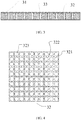
FIG. 4 is a front view of a buffer plate of an end plate according to an embodiment of the present application. -
- 1-cell;
- 2-side plate;
- 21-bending edge;
- 3-end plate;
- 31-panel;
- 32-buffer plate;
- 321-slot;
- 322-supporting hole;
- 323-temperature control hole;
- 33-elastic member;
- 4-screw.
- The accompanying drawings herein are incorporated into the description and constitute a part of the description, which show embodiments of the present application and are used to explain the principles of the present application together with the description.
- The present application is described in further details by the embodiments with reference to the drawings. All the expressions "front", "back", "left", "right", "up" and "down" herein are referred to on the basis of a placement state in the drawings.
- As shown in
FIG. 1 and FIG. 2 , the present application provides a battery module, and the battery module includes a cell 1, aside plate 2 and anend plate 3. Theside plate 2 is connected with theend plate 3, and theside plate 2 and theend plate 3 package the cell 1. - As shown in
FIG. 3 and FIG. 4 , theend plate 3 includes apanel 31, anelastic member 33 and abuffer plate 32. Thepanel 31 and thebuffer plate 32 are stacked, i.e., thepanel 31 is parallel to thebuffer plate 32 and is attached to thebuffer plate 32. A supportinghole 322 is defined in thebuffer plate 32, and the supportinghole 322 is a through hole along a thickness direction of thebuffer plate 32. Theelastic member 33 is inserted in the supportinghole 322, and an end of theelastic member 33 abuts against thepanel 31. Theend plate 3 further includes a temperature control member. - Since the
end plate 3 is formed by thepanel 31 and thebuffer plate 32, when the battery module is subjected to an external impact, thebuffer plate 32 and/or theelastic member 33 can deform to buffer the impact force, so as to avoid theend plate 3 from directly squeezing the cell 1. Therefore, the cell 1 is protected and the safety of the battery module is guaranteed. - An elasticity coefficient of the
elastic member 33 may be greater than, equal to, or smaller than an elasticity coefficient of thebuffer plate 32. Preferably, the elasticity coefficient of theelastic member 33 is greater than the elasticity coefficient of thebuffer plate 32, so as to avoid elastic failure of thebuffer plate 32. During assembling of theend plate 3 with theside plate 2, theelastic member 33 forms a frame with no deformation or slight deformation to resist against the compression force during assembling, so as to buffer the squeeze to the cell 1 resulted from too much assembling force. In the meantime, even if a high internal expansion force is generated when the battery module is in use or an accident occurs, theelastic member 33 can play a major role in resisting against deformation, and thebuffer plate 32 can play a secondary role in resisting against deformation. When the deformation amount generated due to an external force is less than a reversible deformation amount of theelastic member 33 and thebuffer plate 32, theelastic member 33 and thebuffer plate 32 will recover to the original state after the external force is withdrew. When the external force is excessively great, theelastic member 33 and thebuffer plate 32 will irreversibly deform to buffer the external force in a certain extent, so as to reduce the damage caused by the external force to the battery module. Thepanel 31 can be a metal plate or a resin plate, and thepanel 31 is preferred to be a resin plate, so as to reduce the overall weight of the battery module. Further, in order to increase the strength of thepanel 31, the resin plate is preferably a continuous fiber-reinforced resin plate, and the continuous fiber-reinforced resin plate is a composite of one of unsaturated polyester resin, unsaturated epoxy vinyl polyester resin, epoxy resin and phenolic resin, and at least one of fiberglass mesh, axial glass fabric, fiberglass complex felt, carbon-fiber mesh, axial carbon-fiber fabric and carbon-fiber complex felt, so as to facilitate the processing and forming. Thepanel 31 and theelastic member 33 cooperatively form a frame which plays a major role in resisting against deformation during assembling. - The
buffer plate 32 may be made of foam, for example, polyvinyl chloride foam (PVC foam), polyurethane foam (PU foam), polyethylene terephthalate foam (PET foam), polymethacrylimide foam (PMI foam), etc., or made of other elastic materials, for example, rubber, etc. Thebuffer plate 32 is preferably made of foam, so as to facilitate the forming. - The
elastic member 33 may be made of at least one of resin, spring and rubber, so as to facilitate material acquiring and forming. The supportinghole 322 is fitted to theelastic member 33, so that it is guaranteed that theelastic member 33 merely deforms elastically along a thickness direction of thebuffer plate 32 to have a better buffering effect. - The
elastic member 33 and thepanel 31 can be integrated as a whole, or separately formed and then connected with each other. Theelastic member 33 and thepanel 31 are preferably integrated as a whole, particularly, when both thepanel 31 and theelastic member 33 are made of resin, theelastic member 33 and thepanel 31 can be integrated as a whole by vacuum molding or resin transfer molding (Resin Transfer Molding, RTM), so as to improve connection reliability of theend plate 3 and simplify the assembling procedure. - The
end plate 3 may further include a temperature control member, and the temperature control member may be made of a solid-solid phase change material or a solid-liquid phase change material, and thepanel 31 is covered by a solid-liquid phase change material. When the temperature control member is included, atemperature control hole 323 is defined in thebuffer plate 32, the temperature control member is filled into thetemperature control hole 323, and an end of the temperature control member is attached to thepanel 31. Therefore, the heat exchange between the interior of the battery module and the external environment can be accelerated when the temperature in the battery module is strictly required, so as to guarantee the temperature of the battery module. - The
panel 31 can be connected with thebuffer plate 32 by adhering, clamping or screwing, and adhering is preferred so as to increase attachment degree between thepanel 31 and thebuffer plate 32. When thepanel 31 is adhered with thebuffer plate 32, theend plate 3 further includes an adhesive (i.e., a structural adhesive) located between thepanel 31 and thebuffer plate 32. The adhesive may be a double-component polyurethane adhesive, an acrylic adhesive or an epoxy resin adhesive. The adhesive can also be a heat conductive adhesive which can increase heat conduction of the battery module. - In order to provide better adhesive bonding effect, a
slot 321 is defined at each of two sides of thebuffer plate 32, and the adhesive is filled in theslot 321. When thepanel 31 is made of a resin, theslot 321 may be filled with the resin, or be filled with the adhesive and the resin. - The
slot 321 may merely include a transverse slot or a longitudinal slot. Or, theslot 321 may form a crisscrossing adhesive bonding structure to increase the adhesive bonding effect between thepanel 31 and thebuffer plate 32, as shown inFIG. 4 , theslot 321 includes a plurality of transverse slots and a plurality of longitudinal slots, and the plurality of transverse slots and the plurality of longitudinal slots intersect with each other, e.g., perpendicularly or with a non-right included angle. A plurality of supportingholes 322 may be defined at intersections of the plurality of transverse slots and the plurality of longitudinal slots, so as to guarantee the strength of thebuffer plate 32. - When the
temperature control hole 323 is defined in thebuffer plate 32, thetemperature control hole 323 may be defined in any position of the transverse slot or the longitudinal slot, or an area defined by every two adjacent transverse slots and every two adjacent longitudinal slots is provided with a plurality of temperature control holes 323. Preferably, an area defined by every two adjacent transverse slots and every two adjacent longitudinal slots is provided with onetemperature control hole 323, so as to guarantee the strength of thebuffer plate 32. - The
end plate 3 may include only onepanel 31, and thebuffer plate 32 is closer to the cell 1 of the battery module than thepanel 31; or, theend plate 3 includes twopanels 31. Preferably, theend plate 3 includes twopanels 31, thebuffer plate 32 is located between the twopanels 31, and two ends of theelastic member 33 abut against the twopanels 31, respectively. When the temperature control member is included, two ends of the temperature control member abut against the twopanels 31, respectively. With the twopanels 31, theend plate 3 is formed into a "sandwich" structure and has improved reliability. - The
side plate 2 may include a bendingedge 21, the bendingedge 21 bends toward the interior of the battery module, and theend plate 3 is connected with the bendingedge 21 of theside plate 2. With the bendingedge 21, the contact area between theend plate 3 and theside plate 2 is increased, and the connection reliability of theend plate 2 and theside plate 2 is guaranteed. - The
end plate 3 may be located at the inner side of the bendingedge 21, i.e., theend plate 3 is located at a side of the bendingedge 21 close to the cell 1. Or, theend plate 3 is located at the outer side of the bendingedge 21, i.e., theend plate 3 is located at a side of the bendingedge 21 away from the cell 1. Preferably, theend plate 3 is located at the inner side of the bendingedge 21 and is close to the cell 1, so that the position of theend plate 3 can be limited during assembling of theend plate 3 with theside plate 2, and theend plate 3 could be closer to the cell 1, so as to provide better heat conduction effect. - The
end plate 3 may be adhered with theside plate 2, especially, when theside plate 2 include the bendingedge 21, an adhesive is filled between theend plate 3 and the bendingedge 21. Theend plate 3 may also be connected with theside plate 2 by clamping or screwing, as shown inFIG. 1 , theend plate 3 is connected with the side plate by ascrew 4. Preferably, theend plate 3 is adhered with theside plate 2 and, at the same time, theend plate 3 is screwed with theside plate 2 by thescrew 4, which improves the connection reliability between theend plate 3 and theside plate 2. - The above are merely preferred embodiments of the present application, which are not used to limit the present application. The present application can have various modifications and changes for those skilled in the art. All the amendments, equivalent replacements and improvements made to the present application within principles of the present application shall fall into the protection scope of the present application.
Claims (10)
- An end plate of a battery module, characterized in that, the end plate comprises a panel, an elastic member and a buffer plate, wherein the panel and the buffer plate are stacked, a supporting hole is defined in the buffer plate, the supporting hole is a through hole along a thickness direction of the buffer plate, the elastic member is filled in the supporting hole, and an end of the elastic member abuts against the panel.
- The end plate of a battery module according to claim 1, characterized in that, the end plate further comprises a temperature control member; wherein a temperature control hole is defined in the buffer plate, the temperature control member is filled in the temperature control hole, and an end of the temperature control member is attached to the panel.
- The end plate of a battery module according to claim 1, characterized in that, the elastic member and the panel are integrated as a whole.
- The end plate of a battery module according to claim 2, characterized in that, the end plate further comprises an adhesive located between the panel and the buffer plate.
- The end plate of a battery module according to claim 4, characterized in that, the panel is made of a resin, a slot is defined at each of two sides of the buffer plate, and the slot is filled with the adhesive and/or the resin.
- The end plate of a battery module according to claim 5, characterized in that, the slot comprises a plurality of transverse slots and a plurality of longitudinal slots, the plurality of transverse slots and the plurality of longitudinal slots intersect with each other, and the supporting hole is defined at an intersection of one of the plurality of transverse slots and one of the plurality of longitudinal slots.
- The end plate of a battery module according to claim 6, characterized in that, one of the temperature control hole is defined in each area defined by every two adjacent transverse slots and every two adjacent longitudinal slots.
- The end plate of a battery module according to any one of claims 1-7, characterized in that, the end plate comprises two panels, wherein the buffer plate is located between the two panels, and two ends of the elastic member abut against the two panels, respectively.
- A battery module, characterized in that, the battery module comprises a cell, a side plate and the end plate according to any one of claims 1-8, wherein the side plate is connected with the end plate, and the buffer plate is closer to the cell than the panel when the end plate comprises only one panel.
- The battery module according to claim 9, characterized in that, the side plate comprises a bending edge, the bending edge bends toward an interior of the battery module, and the end plate is connected with the bending edge of the side plate.
Applications Claiming Priority (1)
| Application Number | Priority Date | Filing Date | Title |
|---|---|---|---|
| CN201620801338.1U CN205828488U (en) | 2016-07-28 | 2016-07-28 | Cell end plate and battery modules |
Publications (2)
| Publication Number | Publication Date |
|---|---|
| EP3279971A1 true EP3279971A1 (en) | 2018-02-07 |
| EP3279971B1 EP3279971B1 (en) | 2019-07-03 |
Family
ID=57556507
Family Applications (1)
| Application Number | Title | Priority Date | Filing Date |
|---|---|---|---|
| EP17181356.1A Active EP3279971B1 (en) | 2016-07-28 | 2017-07-14 | End plate of battery module and battery module |
Country Status (3)
| Country | Link |
|---|---|
| US (1) | US10236489B2 (en) |
| EP (1) | EP3279971B1 (en) |
| CN (1) | CN205828488U (en) |
Families Citing this family (13)
| Publication number | Priority date | Publication date | Assignee | Title |
|---|---|---|---|---|
| JP7053162B2 (en) * | 2017-04-05 | 2022-04-12 | トヨタ自動車株式会社 | Stacked battery module |
| US11476541B2 (en) * | 2017-05-12 | 2022-10-18 | Sanyo Electric Co., Ltd. | Power supply device, vehicle equipped with same, power storage device and separator for power supply device |
| CN107768566B (en) * | 2017-09-30 | 2024-02-13 | 杭州捷能科技有限公司 | Battery module convenient to dismouting |
| JP6637951B2 (en) * | 2017-12-12 | 2020-01-29 | 本田技研工業株式会社 | Vehicle battery unit |
| US20190273295A1 (en) * | 2018-03-05 | 2019-09-05 | Anhui Xinen Technology Co., Ltd. | Regenerative solid-solid phase change cooling for an energy storage device |
| CN110323379B (en) * | 2018-03-30 | 2022-09-27 | 本田技研工业株式会社 | Battery module and method for manufacturing end plate |
| US11724604B2 (en) * | 2018-06-25 | 2023-08-15 | Ford Global Technologies, Llc | Split panel array plate assemblies for electrified vehicle battery packs |
| JP7061547B2 (en) * | 2018-10-02 | 2022-04-28 | 本田技研工業株式会社 | Battery module and method of manufacturing battery module |
| KR102378527B1 (en) * | 2018-12-05 | 2022-03-23 | 주식회사 엘지에너지솔루션 | Battery module and the method of manufacturing the same |
| KR20210103280A (en) * | 2020-02-13 | 2021-08-23 | 현대자동차주식회사 | Battery storage device for electric vehicle |
| CN113437427A (en) * | 2020-03-05 | 2021-09-24 | 奥迪股份公司 | Battery system and vehicle |
| KR20230036393A (en) * | 2021-09-07 | 2023-03-14 | 삼성에스디아이 주식회사 | Rechargeable battery module |
| DE102022211184A1 (en) | 2022-10-21 | 2024-05-02 | Robert Bosch Gesellschaft mit beschränkter Haftung | Battery module, method for producing the same and end plate unit |
Citations (2)
| Publication number | Priority date | Publication date | Assignee | Title |
|---|---|---|---|---|
| US20150093607A1 (en) * | 2012-03-29 | 2015-04-02 | Sanyo Electric Co., Ltd. | Power supply device, and vehicle and storage battery device equipped with power supply device |
| EP2958165A1 (en) * | 2013-02-15 | 2015-12-23 | Hitachi Automotive Systems, Ltd. | Secondary battery module |
Family Cites Families (1)
| Publication number | Priority date | Publication date | Assignee | Title |
|---|---|---|---|---|
| WO2010106753A1 (en) * | 2009-03-17 | 2010-09-23 | パナソニック株式会社 | Fuel cell stack |
-
2016
- 2016-07-28 CN CN201620801338.1U patent/CN205828488U/en active Active
-
2017
- 2017-07-13 US US15/648,496 patent/US10236489B2/en active Active
- 2017-07-14 EP EP17181356.1A patent/EP3279971B1/en active Active
Patent Citations (2)
| Publication number | Priority date | Publication date | Assignee | Title |
|---|---|---|---|---|
| US20150093607A1 (en) * | 2012-03-29 | 2015-04-02 | Sanyo Electric Co., Ltd. | Power supply device, and vehicle and storage battery device equipped with power supply device |
| EP2958165A1 (en) * | 2013-02-15 | 2015-12-23 | Hitachi Automotive Systems, Ltd. | Secondary battery module |
Also Published As
| Publication number | Publication date |
|---|---|
| US20180034024A1 (en) | 2018-02-01 |
| US10236489B2 (en) | 2019-03-19 |
| EP3279971B1 (en) | 2019-07-03 |
| CN205828488U (en) | 2016-12-21 |
Similar Documents
| Publication | Publication Date | Title |
|---|---|---|
| EP3279971A1 (en) | End plate of battery module and battery module | |
| US10050244B2 (en) | Battery module | |
| US10908651B2 (en) | Electronic device housing | |
| EP3451407B1 (en) | Frame and battery module | |
| US8372495B2 (en) | Electronic device enclosure using sandwich construction | |
| EP2551110A1 (en) | Impact resistant device comprising an optical layer | |
| EP3654407B1 (en) | Casing for accomodating battery module and battery pack | |
| EP2696389A1 (en) | Secondary battery apparatus and method of manufacturing secondary battery apparatus | |
| KR20140113017A (en) | Back cover for supporting display panel and method for producing the same | |
| WO2011111286A1 (en) | Solar cell module and method for reinforcing solar cell module | |
| KR102111188B1 (en) | Casing member and electronic apparatus | |
| JP2023503506A (en) | Battery packs and electric vehicles | |
| EP3568740B1 (en) | Composite unibody keyboard | |
| CN212256768U (en) | Display panel and display device | |
| JP6372141B2 (en) | Shock absorbing structure and vehicle outer plate member having the same | |
| CN217651143U (en) | Anti-explosion protective film for mobile phone rear cover | |
| WO2018150794A1 (en) | Solar cell module | |
| JP5095506B2 (en) | Reinforced laminate | |
| JP6728584B2 (en) | Positioning member, battery pack including the same, and positioning method | |
| WO2017150045A1 (en) | Solar cell module | |
| WO2017145663A1 (en) | Solar cell module | |
| CN216597787U (en) | End plate and battery module | |
| KR20210061142A (en) | Fiber reinforced polymer composite back frame for solar cell panel and solar cell panel intergrated with the same | |
| CN216818521U (en) | Electronic device | |
| CN213227922U (en) | Anti-static PP (polypropylene) plate for draw-bar box |
Legal Events
| Date | Code | Title | Description |
|---|---|---|---|
| PUAI | Public reference made under article 153(3) epc to a published international application that has entered the european phase |
Free format text: ORIGINAL CODE: 0009012 |
|
| STAA | Information on the status of an ep patent application or granted ep patent |
Free format text: STATUS: REQUEST FOR EXAMINATION WAS MADE |
|
| 17P | Request for examination filed |
Effective date: 20170714 |
|
| AK | Designated contracting states |
Kind code of ref document: A1 Designated state(s): AL AT BE BG CH CY CZ DE DK EE ES FI FR GB GR HR HU IE IS IT LI LT LU LV MC MK MT NL NO PL PT RO RS SE SI SK SM TR |
|
| AX | Request for extension of the european patent |
Extension state: BA ME |
|
| RBV | Designated contracting states (corrected) |
Designated state(s): AL AT BE BG CH CY CZ DE DK EE ES FI FR GB GR HR HU IE IS IT LI LT LU LV MC MK MT NL NO PL PT RO RS SE SI SK SM TR |
|
| GRAP | Despatch of communication of intention to grant a patent |
Free format text: ORIGINAL CODE: EPIDOSNIGR1 |
|
| STAA | Information on the status of an ep patent application or granted ep patent |
Free format text: STATUS: GRANT OF PATENT IS INTENDED |
|
| INTG | Intention to grant announced |
Effective date: 20190128 |
|
| GRAS | Grant fee paid |
Free format text: ORIGINAL CODE: EPIDOSNIGR3 |
|
| GRAA | (expected) grant |
Free format text: ORIGINAL CODE: 0009210 |
|
| STAA | Information on the status of an ep patent application or granted ep patent |
Free format text: STATUS: THE PATENT HAS BEEN GRANTED |
|
| AK | Designated contracting states |
Kind code of ref document: B1 Designated state(s): AL AT BE BG CH CY CZ DE DK EE ES FI FR GB GR HR HU IE IS IT LI LT LU LV MC MK MT NL NO PL PT RO RS SE SI SK SM TR |
|
| REG | Reference to a national code |
Ref country code: GB Ref legal event code: FG4D |
|
| REG | Reference to a national code |
Ref country code: CH Ref legal event code: EP Ref country code: AT Ref legal event code: REF Ref document number: 1152047 Country of ref document: AT Kind code of ref document: T Effective date: 20190715 |
|
| REG | Reference to a national code |
Ref country code: DE Ref legal event code: R096 Ref document number: 602017004970 Country of ref document: DE |
|
| REG | Reference to a national code |
Ref country code: IE Ref legal event code: FG4D |
|
| REG | Reference to a national code |
Ref country code: NL Ref legal event code: MP Effective date: 20190703 |
|
| REG | Reference to a national code |
Ref country code: LT Ref legal event code: MG4D |
|
| REG | Reference to a national code |
Ref country code: AT Ref legal event code: MK05 Ref document number: 1152047 Country of ref document: AT Kind code of ref document: T Effective date: 20190703 |
|
| PG25 | Lapsed in a contracting state [announced via postgrant information from national office to epo] |
Ref country code: FI Free format text: LAPSE BECAUSE OF FAILURE TO SUBMIT A TRANSLATION OF THE DESCRIPTION OR TO PAY THE FEE WITHIN THE PRESCRIBED TIME-LIMIT Effective date: 20190703 Ref country code: CZ Free format text: LAPSE BECAUSE OF FAILURE TO SUBMIT A TRANSLATION OF THE DESCRIPTION OR TO PAY THE FEE WITHIN THE PRESCRIBED TIME-LIMIT Effective date: 20190703 Ref country code: NO Free format text: LAPSE BECAUSE OF FAILURE TO SUBMIT A TRANSLATION OF THE DESCRIPTION OR TO PAY THE FEE WITHIN THE PRESCRIBED TIME-LIMIT Effective date: 20191003 Ref country code: BG Free format text: LAPSE BECAUSE OF FAILURE TO SUBMIT A TRANSLATION OF THE DESCRIPTION OR TO PAY THE FEE WITHIN THE PRESCRIBED TIME-LIMIT Effective date: 20191003 Ref country code: AT Free format text: LAPSE BECAUSE OF FAILURE TO SUBMIT A TRANSLATION OF THE DESCRIPTION OR TO PAY THE FEE WITHIN THE PRESCRIBED TIME-LIMIT Effective date: 20190703 Ref country code: NL Free format text: LAPSE BECAUSE OF FAILURE TO SUBMIT A TRANSLATION OF THE DESCRIPTION OR TO PAY THE FEE WITHIN THE PRESCRIBED TIME-LIMIT Effective date: 20190703 Ref country code: PT Free format text: LAPSE BECAUSE OF FAILURE TO SUBMIT A TRANSLATION OF THE DESCRIPTION OR TO PAY THE FEE WITHIN THE PRESCRIBED TIME-LIMIT Effective date: 20191104 Ref country code: SE Free format text: LAPSE BECAUSE OF FAILURE TO SUBMIT A TRANSLATION OF THE DESCRIPTION OR TO PAY THE FEE WITHIN THE PRESCRIBED TIME-LIMIT Effective date: 20190703 Ref country code: LT Free format text: LAPSE BECAUSE OF FAILURE TO SUBMIT A TRANSLATION OF THE DESCRIPTION OR TO PAY THE FEE WITHIN THE PRESCRIBED TIME-LIMIT Effective date: 20190703 Ref country code: HR Free format text: LAPSE BECAUSE OF FAILURE TO SUBMIT A TRANSLATION OF THE DESCRIPTION OR TO PAY THE FEE WITHIN THE PRESCRIBED TIME-LIMIT Effective date: 20190703 |
|
| PG25 | Lapsed in a contracting state [announced via postgrant information from national office to epo] |
Ref country code: RS Free format text: LAPSE BECAUSE OF FAILURE TO SUBMIT A TRANSLATION OF THE DESCRIPTION OR TO PAY THE FEE WITHIN THE PRESCRIBED TIME-LIMIT Effective date: 20190703 Ref country code: AL Free format text: LAPSE BECAUSE OF FAILURE TO SUBMIT A TRANSLATION OF THE DESCRIPTION OR TO PAY THE FEE WITHIN THE PRESCRIBED TIME-LIMIT Effective date: 20190703 Ref country code: LV Free format text: LAPSE BECAUSE OF FAILURE TO SUBMIT A TRANSLATION OF THE DESCRIPTION OR TO PAY THE FEE WITHIN THE PRESCRIBED TIME-LIMIT Effective date: 20190703 Ref country code: ES Free format text: LAPSE BECAUSE OF FAILURE TO SUBMIT A TRANSLATION OF THE DESCRIPTION OR TO PAY THE FEE WITHIN THE PRESCRIBED TIME-LIMIT Effective date: 20190703 Ref country code: GR Free format text: LAPSE BECAUSE OF FAILURE TO SUBMIT A TRANSLATION OF THE DESCRIPTION OR TO PAY THE FEE WITHIN THE PRESCRIBED TIME-LIMIT Effective date: 20191004 Ref country code: IS Free format text: LAPSE BECAUSE OF FAILURE TO SUBMIT A TRANSLATION OF THE DESCRIPTION OR TO PAY THE FEE WITHIN THE PRESCRIBED TIME-LIMIT Effective date: 20191103 |
|
| PG25 | Lapsed in a contracting state [announced via postgrant information from national office to epo] |
Ref country code: TR Free format text: LAPSE BECAUSE OF FAILURE TO SUBMIT A TRANSLATION OF THE DESCRIPTION OR TO PAY THE FEE WITHIN THE PRESCRIBED TIME-LIMIT Effective date: 20190703 |
|
| REG | Reference to a national code |
Ref country code: BE Ref legal event code: MM Effective date: 20190731 |
|
| PG25 | Lapsed in a contracting state [announced via postgrant information from national office to epo] |
Ref country code: PL Free format text: LAPSE BECAUSE OF FAILURE TO SUBMIT A TRANSLATION OF THE DESCRIPTION OR TO PAY THE FEE WITHIN THE PRESCRIBED TIME-LIMIT Effective date: 20190703 Ref country code: DK Free format text: LAPSE BECAUSE OF FAILURE TO SUBMIT A TRANSLATION OF THE DESCRIPTION OR TO PAY THE FEE WITHIN THE PRESCRIBED TIME-LIMIT Effective date: 20190703 Ref country code: IT Free format text: LAPSE BECAUSE OF FAILURE TO SUBMIT A TRANSLATION OF THE DESCRIPTION OR TO PAY THE FEE WITHIN THE PRESCRIBED TIME-LIMIT Effective date: 20190703 Ref country code: RO Free format text: LAPSE BECAUSE OF FAILURE TO SUBMIT A TRANSLATION OF THE DESCRIPTION OR TO PAY THE FEE WITHIN THE PRESCRIBED TIME-LIMIT Effective date: 20190703 Ref country code: EE Free format text: LAPSE BECAUSE OF FAILURE TO SUBMIT A TRANSLATION OF THE DESCRIPTION OR TO PAY THE FEE WITHIN THE PRESCRIBED TIME-LIMIT Effective date: 20190703 |
|
| PG25 | Lapsed in a contracting state [announced via postgrant information from national office to epo] |
Ref country code: SK Free format text: LAPSE BECAUSE OF FAILURE TO SUBMIT A TRANSLATION OF THE DESCRIPTION OR TO PAY THE FEE WITHIN THE PRESCRIBED TIME-LIMIT Effective date: 20190703 Ref country code: SM Free format text: LAPSE BECAUSE OF FAILURE TO SUBMIT A TRANSLATION OF THE DESCRIPTION OR TO PAY THE FEE WITHIN THE PRESCRIBED TIME-LIMIT Effective date: 20190703 Ref country code: BE Free format text: LAPSE BECAUSE OF NON-PAYMENT OF DUE FEES Effective date: 20190731 Ref country code: IS Free format text: LAPSE BECAUSE OF FAILURE TO SUBMIT A TRANSLATION OF THE DESCRIPTION OR TO PAY THE FEE WITHIN THE PRESCRIBED TIME-LIMIT Effective date: 20200224 Ref country code: LU Free format text: LAPSE BECAUSE OF NON-PAYMENT OF DUE FEES Effective date: 20190714 Ref country code: MC Free format text: LAPSE BECAUSE OF FAILURE TO SUBMIT A TRANSLATION OF THE DESCRIPTION OR TO PAY THE FEE WITHIN THE PRESCRIBED TIME-LIMIT Effective date: 20190703 |
|
| REG | Reference to a national code |
Ref country code: DE Ref legal event code: R097 Ref document number: 602017004970 Country of ref document: DE |
|
| PLBE | No opposition filed within time limit |
Free format text: ORIGINAL CODE: 0009261 |
|
| STAA | Information on the status of an ep patent application or granted ep patent |
Free format text: STATUS: NO OPPOSITION FILED WITHIN TIME LIMIT |
|
| PG2D | Information on lapse in contracting state deleted |
Ref country code: IS |
|
| PG25 | Lapsed in a contracting state [announced via postgrant information from national office to epo] |
Ref country code: IE Free format text: LAPSE BECAUSE OF NON-PAYMENT OF DUE FEES Effective date: 20190714 |
|
| 26N | No opposition filed |
Effective date: 20200603 |
|
| PG25 | Lapsed in a contracting state [announced via postgrant information from national office to epo] |
Ref country code: SI Free format text: LAPSE BECAUSE OF FAILURE TO SUBMIT A TRANSLATION OF THE DESCRIPTION OR TO PAY THE FEE WITHIN THE PRESCRIBED TIME-LIMIT Effective date: 20190703 |
|
| REG | Reference to a national code |
Ref country code: DE Ref legal event code: R079 Ref document number: 602017004970 Country of ref document: DE Free format text: PREVIOUS MAIN CLASS: H01M0002100000 Ipc: H01M0050200000 |
|
| REG | Reference to a national code |
Ref country code: CH Ref legal event code: PL |
|
| PG25 | Lapsed in a contracting state [announced via postgrant information from national office to epo] |
Ref country code: CH Free format text: LAPSE BECAUSE OF NON-PAYMENT OF DUE FEES Effective date: 20200731 Ref country code: LI Free format text: LAPSE BECAUSE OF NON-PAYMENT OF DUE FEES Effective date: 20200731 |
|
| PG25 | Lapsed in a contracting state [announced via postgrant information from national office to epo] |
Ref country code: CY Free format text: LAPSE BECAUSE OF FAILURE TO SUBMIT A TRANSLATION OF THE DESCRIPTION OR TO PAY THE FEE WITHIN THE PRESCRIBED TIME-LIMIT Effective date: 20190703 |
|
| PG25 | Lapsed in a contracting state [announced via postgrant information from national office to epo] |
Ref country code: MT Free format text: LAPSE BECAUSE OF FAILURE TO SUBMIT A TRANSLATION OF THE DESCRIPTION OR TO PAY THE FEE WITHIN THE PRESCRIBED TIME-LIMIT Effective date: 20190703 Ref country code: HU Free format text: LAPSE BECAUSE OF FAILURE TO SUBMIT A TRANSLATION OF THE DESCRIPTION OR TO PAY THE FEE WITHIN THE PRESCRIBED TIME-LIMIT; INVALID AB INITIO Effective date: 20170714 |
|
| PG25 | Lapsed in a contracting state [announced via postgrant information from national office to epo] |
Ref country code: MK Free format text: LAPSE BECAUSE OF FAILURE TO SUBMIT A TRANSLATION OF THE DESCRIPTION OR TO PAY THE FEE WITHIN THE PRESCRIBED TIME-LIMIT Effective date: 20190703 |
|
| P01 | Opt-out of the competence of the unified patent court (upc) registered |
Effective date: 20230516 |
|
| PGFP | Annual fee paid to national office [announced via postgrant information from national office to epo] |
Ref country code: DE Payment date: 20230516 Year of fee payment: 7 |
|
| PGFP | Annual fee paid to national office [announced via postgrant information from national office to epo] |
Ref country code: GB Payment date: 20240524 Year of fee payment: 8 |
|
| PGFP | Annual fee paid to national office [announced via postgrant information from national office to epo] |
Ref country code: FR Payment date: 20240524 Year of fee payment: 8 |
|
| REG | Reference to a national code |
Ref country code: DE Ref legal event code: R082 Ref document number: 602017004970 Country of ref document: DE Ref country code: DE Ref legal event code: R081 Ref document number: 602017004970 Country of ref document: DE Owner name: CONTEMPORARY AMPEREX TECHNOLOGY (HONG KONG) LI, HK Free format text: FORMER OWNER: CONTEMPORARY AMPEREX TECHNOLOGY CO., LTD., NINGDE CITY, FUJIAN, CN |
|
| REG | Reference to a national code |
Ref country code: GB Ref legal event code: 732E Free format text: REGISTERED BETWEEN 20240815 AND 20240821 |