EP3279912A1 - Switch device - Google Patents
Switch device Download PDFInfo
- Publication number
- EP3279912A1 EP3279912A1 EP17181348.8A EP17181348A EP3279912A1 EP 3279912 A1 EP3279912 A1 EP 3279912A1 EP 17181348 A EP17181348 A EP 17181348A EP 3279912 A1 EP3279912 A1 EP 3279912A1
- Authority
- EP
- European Patent Office
- Prior art keywords
- operation knob
- switch
- resilient
- substrate
- resilient dome
- Prior art date
- Legal status (The legal status is an assumption and is not a legal conclusion. Google has not performed a legal analysis and makes no representation as to the accuracy of the status listed.)
- Granted
Links
Images


Classifications
-
- H—ELECTRICITY
- H01—ELECTRIC ELEMENTS
- H01H—ELECTRIC SWITCHES; RELAYS; SELECTORS; EMERGENCY PROTECTIVE DEVICES
- H01H25/00—Switches with compound movement of handle or other operating part
- H01H25/04—Operating part movable angularly in more than one plane, e.g. joystick
- H01H25/041—Operating part movable angularly in more than one plane, e.g. joystick having a generally flat operating member depressible at different locations to operate different controls
-
- B—PERFORMING OPERATIONS; TRANSPORTING
- B60—VEHICLES IN GENERAL
- B60Q—ARRANGEMENT OF SIGNALLING OR LIGHTING DEVICES, THE MOUNTING OR SUPPORTING THEREOF OR CIRCUITS THEREFOR, FOR VEHICLES IN GENERAL
- B60Q1/00—Arrangement of optical signalling or lighting devices, the mounting or supporting thereof or circuits therefor
- B60Q1/0076—Switches therefor
- B60Q1/0082—Switches therefor mounted on the steering wheel
-
- H—ELECTRICITY
- H01—ELECTRIC ELEMENTS
- H01H—ELECTRIC SWITCHES; RELAYS; SELECTORS; EMERGENCY PROTECTIVE DEVICES
- H01H2215/00—Tactile feedback
- H01H2215/004—Collapsible dome or bubble
- H01H2215/006—Only mechanical function
-
- H—ELECTRICITY
- H01—ELECTRIC ELEMENTS
- H01H—ELECTRIC SWITCHES; RELAYS; SELECTORS; EMERGENCY PROTECTIVE DEVICES
- H01H2215/00—Tactile feedback
- H01H2215/004—Collapsible dome or bubble
- H01H2215/008—Part of substrate or membrane
Definitions
- This invention relates to a switch device and, in particular, to a switch device that has a backlash reducing structure for an operation knob.
- a switch device is known in which a push button attaching structure to reduce a backlash is proposed (see e.g. JP-A- 2015-095415 ).
- the push button attaching structure disclosed by JP-A- 2015-095415 is provided with a push button having a rectangular shape in a front view is movably attached to a main body, and plural long leaf springs that bias the push button in a direction to separate the push button from the main body are arranged at multiple positions except a center of the push button.
- the leaf springs are formed by cutting and raising a part of the main body surrounded by a slit formed by piercing the main body. A tip portion of the leaf spring in a longitudinal direction thereof contacts the push button when the push button is pushed.
- JP-A- 2015-095415 discloses the push button attaching structure that allows the leaf springs to locate at multiple positions except the center of the push button.
- this structure is configured so as to decrease the distance from the leaf spring to the tip portion for reducing the backlash in the push button.
- JP-A- 2015-095415 teaches the push button attaching structure that is provided with the plural leaf springs formed by cutting and raising the part of the main body surrounded by the slit formed by piercing the main body.
- the leaf springs may cause a complicated internal structure so as to increase the manufacturing cost.
- a switch device can be provided that prevents the backlash in the operation knob without the complicated internal structure.
- the reference numeral 1 in FIG.1 denotes a steering switch that is a typical switch device according to the present embodiment.
- the steering switches 1 are respectively attached on right and left spokes 5 in viewing the steering wheel 2 in a front view.
- Right and left steering switches 1 comprises practically same shapes and structures.
- the right and left switches 1 are arranged in a direction shown in FIG.1 as an example, the switches 1 are preferable to be arranged in a direction such that the driver's finger can reach and the driver can operate easily.
- an operation knob 10 that can tilting operate in the vertical and horizontal directions is shown, it is not limited to.
- the steering wheel 2 comprises a cylindrical boss (not shown) that is fitted and fixed on an end of a steering shaft (not shown).
- the steering wheel 2 is provided with a pad 3 that is attached on the boss, a ring 4 that covers a ring core metal, and a spoke 5 that covers a part of three spoke core metals that joint the ring core metal in the ring 4 and the boss each other.
- the steering switch 1 which is not limited to thereof, is used as a switch device that outputs an operation signal to operate in-vehicle equipment such as an air-conditioner, an audio device, a car navigation system, and a door mirror. Also, the steering switch 1 is used as a switch device to output an operation signal to change image function or image display corresponding to an icon by choosing and displaying the icon indicated in the display.
- the steering switch 1 comprises the operation knob 10 that is formed in a rhombus shape in viewing the steering wheel 2 in the front view.
- the rhombus opening 12 is formed in an intermediate portion of the operation knob 10.
- An external opening peripheral portion of the opening 12 is configured as a rhombus circular shaped peripheral operation portion in which an operation surface 11 is exposed.
- the operation knob 10 is formed in a cap shape that has an opening opened downwardly.
- the operation knob 10 comprises an upper surface as the operation surface 11 having the rhombus shape, and a peripheral wall portion formed at an outer peripheral edge of the upper surface.
- Four triangular shaped symbols that show operation positions are formed on the upper surface.
- a central operation portion that is formed separately or integrally from the operation knob 10, or various parts such as a design member including an emblem is arranged in the opening 12 of the operation knob 10.
- the central operation portion is preferable to configure as a key for detection switch such that an operator determines an operation of the process corresponding to an operation item indicated in the display, or a key for selection switch such that the operator selects the operation item indicated in the display.
- a resilient dome type structure so as to hold the central operation portion above a switch contact can be used. Moving the central operation portion upwardly is prevented by engaging the central operation portion with an internal opening peripheral portion of the opening 12 of the operation knob 10.
- a spheroidal tilting shaft so as to tilt the operation knob 10 can be provided.
- the tilting shaft can support the operation knob 10 tiltably from the tilting shaft as the reference point by holding the tilting shaft in a spherical holding portion formed by protruding a substrate. Moving the operation knob 10 upwardly is prevented by engaging the tilting shaft with the spherical holding portion of the opening 12 of the operation knob 10.
- the operation knob 10 in a shown example is formed as a four directions switch that can input four directions for the vertical and horizontal directions.
- the operation knob 10 is provided with four switch contacts 15.
- the switch contacts 15 are respectively arranged in four triangular areas that divide the rhombus as the operation surface 11 of the operation knob 10 into first to fourth quadrants across a long axis X and a short axis Y that are diagonal lines of the rhombus.
- the switch contacts 15 are arranged in four directions on the same circumference in the operation surface 11 of the operation knob 10. Predetermined switch signals are generated by tilting the operation knob 10 to any one of the four directions.
- Respective switch contacts 15 are provided with fixed contacts 15a arranged on the substrate 6, and moving contacts 15b that can contact and separate with the fixed contacts 15a. And respective switch contacts 15 have practically same structures.
- Material of the contact is made of metal having conductivity such as copper.
- the substrate 6 is made from a member such as a rigid plate or a flexible plate.
- the fixed contact 15a is connected to a wiring pattern of the substrate 6.
- the switch contact 15 is provided with a resilient sheet 16 made from a member having spring property such as metal, rubber, or soft resin.
- the resilient sheet 16 comprises a resilient dome 17 from which a surface of the resilient sheet 16 which corresponds to the fixed contact 15a is upwardly protruded.
- the resilient dome 17 is operable to resiliently deform and reverse so as to contact the moving contact 15b with the fixed contact 15a at a contact position.
- the resilient dome 17 is configured as a feeling moderation generating member that generates switch feeling moderation.
- the resilient dome 17 is provided with a practically truncated cone shaped skirt 17a, and a circular moving part 17b that forms an upper surface of the skirt 17a.
- the skirt 17a is formed so as to resiliently deform and reverse caused by pressure in switch operating.
- the moving contact 15b is formed at an inner bottom surface of the moving part 17b and is in a non-contact state separated from the fixed contact 15a when the switch is not operated.
- a pusher 13 extended from an inner bottom surface of the operation knob 10 is held on the upper surface of the resilient dome 17.
- the skirt 17a of the resilient dome 17 is reversed when the switch contact is pressed by transmitting operation force for the pusher 13 from the operation knob 10 to the resilient dome 17.
- a lower surface of the moving contact 15b in the resilient dome 17 abuts on the fixed contact 15a on the substrate 6. It causes a switch-on state in which the fixed contact 15a and the moving contact 15b are short-circuited.
- the resilient dome 17 is automatically restored to the former dome shape.
- the moving contact 15b in the resilient dome 17 is released from the fixed contact 15a on the substrate 6. Then the operation knob 10 returns to an early neutral state. Thus, the operation knob 10 is in a switch-off state.
- the steering switch 1 configured as described above has the most important characteristic in a structure to reduce backlash in the operation knob 10 having the rhombus shape in the plan view.
- a rubber dome generally used in switch device is used as a backlash reducing structure. In the shown example, such rubber dome is configured by the resilient dome 18.
- an backlash reducing resilient dome 18 that fails to resiliently deform and reverse in pressing the operation knob 10, and fails to have the switch feeling modification is formed integrally with the resilient sheet 16 at an corner angle portion in both long axes (X direction) of the operation knob 10.
- the resilient dome 18 is arranged at a central end portion corresponding to two sides that puts the long axis X of the operation knob 10 between the two sides. Two resilient domes 18 have the same shape and structure. Common resilient sheet 16 with the resilient sheet 16 forming the switch contact resilient dome 17 is used for the resilient dome 18.
- the backlash reducing resilient dome 18 is provided with a practically truncated cone shaped skirt 18a, and a circular moving part 18b that forms an upper surface of the skirt 18a. Although the backlash reducing resilient dome 18 has practically similar shape to the switch contact resilient dome 17, the backlash reducing resilient dome 18 comprises no moving contact on an inner bottom surface of the moving part 18b.
- the skirt 18a of the resilient dome 18 is preferable to set an angle and a wall thickness so as to deform with small resilient repulsion force against the operation knob 10.
- the pusher 13 extended from the inner bottom surface of the operation knob 10 keeps not reversing the switch contact resilient dome 17. And the pusher 13 is arranged with contacting the backlash reducing resilient dome 18.
- the operation knob 10 is attached on the internal opening peripheral portion of the steering wheel 2 with no preload in the resilient dome 18.
- FIG.5 shows another example of the backlash reducing structure different from the structure shown in FIG.4 .
- a flange 14 protruding outwardly is integrally formed at a peripheral wall edge of the operation knob 10.
- the operation knob 10 is prevented from escaping from the internal opening peripheral portion of the steering wheel 2 by engaging the flange 14 with the internal opening peripheral portion of the steering wheel 2. And the pusher 13 of the operation knob 10 is held on the upper surface of the backlash reducing resilient dome 18.
- the pusher 13 of the operation knob 10 contacts the backlash reducing resilient dome 18 with pressing in engaging the flange 14 of the operation knob 10 with the internal opening peripheral portion of the steering wheel 2.
- the skirt 18a of the resilient dome 18 is pressed with reversing incompletely.
- the preload that the flange 14 of the operation knob 10 presses at the internal opening peripheral portion of the steering wheel 2 is applied by the resilient repulsion force obtained in pressing the skirt 18a.
- a spring property of the backlash reducing resilient dome 18 exhibits behavior as shown in FIG.6 .
- the horizontal axis shows stroke amount S in the preload in the resilient dome 18, and the vertical axis shows the force F applied to the resilient dome 18.
- the point P (S 1 , F 1 ) plotted on the graph shown in FIG.6 is a setting point so as to keep the operation knob 10 with applying the preload. Setting an assembling state to the point P (S 1 , F 1 ) allows the resilient dome 18 can keep constantly applying the preload without a parts error or an assembling error. Moreover, since increasing force is low if the end of the operation knob 10 in the longitudinal direction is pressed, uncomfortable feeling caused by the increasing force can decrease.
- the rubber dome that is the resilient dome 18 generally used in the switch device can be effectively used for the backlash reducing structure of the operation knob 10 without using a spring to bias the knob or an complicated mechanics.
- Backlash in the operation knob 10 can decrease by a simple structure that uses the backlash reducing resilient dome 18 made from the common resilient sheet 16 common with the resilient sheet 16 forming the switch contact resilient dome 17 .
- Degrees of freedoms can increase since a tolerance in a component of the switch device increases.
- the present embodiment is not limited to.
- the backlash reducing structure according to the present embodiment can apply to the operation knob 10 having an operation surface shape such as a rectangular shape a parallelogram, and an elliptic shape, which have the long axis and the short axis that cross in the center.
- backlash reducing resilient dome 18 As the backlash reducing resilient dome 18, it is effective to properly choose conditions such as material, thickness, size, shape, an assemble portion, arrangement number, combined shape, and a spring constant. Several of modification can be allowed.
- a push switch such as a tactile switch may be used as the switch contact 15 instead of a resilient dome type contact member.
- the switch contact 15 may be a structure in which the push switch is arranged in a hollow space of the resilient dome.
- the switch device attached on the steering wheel 2 is shown in the shown examples, it is not limited to.
- the switch device can be arranged at a periphery of driver's sheet such as a door armrest, an instrument panel, and a center console in vehicle interior.
- this switch device can apply to various handheld terminals such as a cellphone and a camera.
Landscapes
- Engineering & Computer Science (AREA)
- Mechanical Engineering (AREA)
- Switches With Compound Operations (AREA)
Abstract
Description
- This invention relates to a switch device and, in particular, to a switch device that has a backlash reducing structure for an operation knob.
- A switch device is known in which a push button attaching structure to reduce a backlash is proposed (see e.g. JP-A-2015-095415).
- The push button attaching structure disclosed by JP-A-2015-095415 is provided with a push button having a rectangular shape in a front view is movably attached to a main body, and plural long leaf springs that bias the push button in a direction to separate the push button from the main body are arranged at multiple positions except a center of the push button. The leaf springs are formed by cutting and raising a part of the main body surrounded by a slit formed by piercing the main body. A tip portion of the leaf spring in a longitudinal direction thereof contacts the push button when the push button is pushed.
- JP-A-2015-095415 discloses the push button attaching structure that allows the leaf springs to locate at multiple positions except the center of the push button. Thus, this structure is configured so as to decrease the distance from the leaf spring to the tip portion for reducing the backlash in the push button.
- JP-A-2015-095415 teaches the push button attaching structure that is provided with the plural leaf springs formed by cutting and raising the part of the main body surrounded by the slit formed by piercing the main body. However, the leaf springs may cause a complicated internal structure so as to increase the manufacturing cost.
- It is an object of the invention to provide a switch device that prevents the backlash in the operation knob without the complicated internal structure.
- (1) According to an embodiment of the invention, a switch device comprises:
- a substrate;
- an operation knob that is arranged above the substrate and that comprises an operation surface formed into a shape comprising a long axis and a short axis;
- a switch contact that is arranged on the substrate corresponding to a region in the operation surface between the long axis and the short axis, and that allows a switching operation according to a press operation of the operation knob; and
- a first resilient dome that is arranged on the substrate corresponding to an end in the long axis, and that is resiliently deformable and is configured to bias the operation knob in a direction separating from the substrate.
- (2) The switch device further comprises a resilient sheet that covers the substrate, and a second resilient dome that is resiliently deformable, and that is integrally formed with the resilient sheet corresponding to the region in the operation surface between the long axis and the short axis, and that allows a switching operation of the switch contact, wherein the first resilient dome is integrally formed with the resilient sheet.
- (3) The first resilient dome is arranged while applying a preload to the operation knob.
- (4) The preload is applied by a member in a periphery of the operation knob, the member being configured to press a part of the operation knob when the operation knob is not in a pressed state.
- (5) The operation knob further comprises a pusher extending downward from an inside surface, and wherein the pusher contacts with the first resilient dome when the operation knob is not in a pressed state.
- (6) The first resilient dome has a same shape as the switch contact and has no switch contact inside the first resilient dome.
- According to an embodiment of the invention, a switch device can be provided that prevents the backlash in the operation knob without the complicated internal structure.
- Next, the present invention will be explained in conjunction with appended drawings, wherein:
-
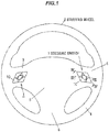
FIG.1 is a plan view schematically explaining an example of a steering wheel comprising a steering switch according to the preferred embodiment in the present invention; -
FIG.2 is a plan view schematically showing an example of the steering switch; -
FIG.3 is a partial cross sectional view showing the steering switch cut along the line III-III inFIG.1 ; -
FIG.4 is a partial cross sectional view showing the steering switch cut along the line IV-IV inFIG.1 ; -
FIG.5 is a partial cross sectional view showing another example of the steering switch corresponding toFIG.4 cut along the line IV-IV inFIG.1 ; and -
FIG.6 is a graph to explain a property of a resilient dome for preloading that is applied to the steering switch. - Next, the embodiment according to the present invention will be described below with reference to the appended drawings.
- The
reference numeral 1 inFIG.1 denotes a steering switch that is a typical switch device according to the present embodiment. Thesteering switches 1 are respectively attached on right andleft spokes 5 in viewing thesteering wheel 2 in a front view. Right andleft steering switches 1 comprises practically same shapes and structures. Although the right andleft switches 1 are arranged in a direction shown inFIG.1 as an example, theswitches 1 are preferable to be arranged in a direction such that the driver's finger can reach and the driver can operate easily. Meanwhile, as an example of thesteering switch 1, although anoperation knob 10 that can tilting operate in the vertical and horizontal directions is shown, it is not limited to. - The
steering wheel 2 comprises a cylindrical boss (not shown) that is fitted and fixed on an end of a steering shaft (not shown). Thesteering wheel 2 is provided with apad 3 that is attached on the boss, a ring 4 that covers a ring core metal, and aspoke 5 that covers a part of three spoke core metals that joint the ring core metal in the ring 4 and the boss each other. - For example, the
steering switch 1, which is not limited to thereof, is used as a switch device that outputs an operation signal to operate in-vehicle equipment such as an air-conditioner, an audio device, a car navigation system, and a door mirror. Also, thesteering switch 1 is used as a switch device to output an operation signal to change image function or image display corresponding to an icon by choosing and displaying the icon indicated in the display. - As shown in
FIGS.1 to 3 , thesteering switch 1 comprises theoperation knob 10 that is formed in a rhombus shape in viewing thesteering wheel 2 in the front view. The rhombus opening 12 is formed in an intermediate portion of theoperation knob 10. An external opening peripheral portion of theopening 12 is configured as a rhombus circular shaped peripheral operation portion in which anoperation surface 11 is exposed. - The
operation knob 10 is formed in a cap shape that has an opening opened downwardly. Theoperation knob 10 comprises an upper surface as theoperation surface 11 having the rhombus shape, and a peripheral wall portion formed at an outer peripheral edge of the upper surface. Four triangular shaped symbols that show operation positions are formed on the upper surface. - A central operation portion that is formed separately or integrally from the
operation knob 10, or various parts such as a design member including an emblem is arranged in theopening 12 of theoperation knob 10. For example, the central operation portion is preferable to configure as a key for detection switch such that an operator determines an operation of the process corresponding to an operation item indicated in the display, or a key for selection switch such that the operator selects the operation item indicated in the display. - As an example of the central operation portion formed separately from the
operation knob 10, a resilient dome type structure so as to hold the central operation portion above a switch contact can be used. Moving the central operation portion upwardly is prevented by engaging the central operation portion with an internal opening peripheral portion of the opening 12 of theoperation knob 10. - As an example of the central operation portion formed integrally with the
operation knob 10, a spheroidal tilting shaft so as to tilt theoperation knob 10 can be provided. For example, the tilting shaft can support theoperation knob 10 tiltably from the tilting shaft as the reference point by holding the tilting shaft in a spherical holding portion formed by protruding a substrate. Moving theoperation knob 10 upwardly is prevented by engaging the tilting shaft with the spherical holding portion of the opening 12 of theoperation knob 10. - The
operation knob 10 in a shown example is formed as a four directions switch that can input four directions for the vertical and horizontal directions. Theoperation knob 10 is provided with fourswitch contacts 15. Theswitch contacts 15 are respectively arranged in four triangular areas that divide the rhombus as theoperation surface 11 of theoperation knob 10 into first to fourth quadrants across a long axis X and a short axis Y that are diagonal lines of the rhombus. Theswitch contacts 15 are arranged in four directions on the same circumference in theoperation surface 11 of theoperation knob 10. Predetermined switch signals are generated by tilting theoperation knob 10 to any one of the four directions. -
Respective switch contacts 15 are provided with fixedcontacts 15a arranged on thesubstrate 6, and movingcontacts 15b that can contact and separate with the fixedcontacts 15a. Andrespective switch contacts 15 have practically same structures. Material of the contact is made of metal having conductivity such as copper. Thesubstrate 6 is made from a member such as a rigid plate or a flexible plate. The fixedcontact 15a is connected to a wiring pattern of thesubstrate 6. - The
switch contact 15 is provided with aresilient sheet 16 made from a member having spring property such as metal, rubber, or soft resin. Theresilient sheet 16 comprises aresilient dome 17 from which a surface of theresilient sheet 16 which corresponds to the fixedcontact 15a is upwardly protruded. Theresilient dome 17 is operable to resiliently deform and reverse so as to contact the movingcontact 15b with the fixedcontact 15a at a contact position. Theresilient dome 17 is configured as a feeling moderation generating member that generates switch feeling moderation. - The
resilient dome 17 is provided with a practically truncated cone shapedskirt 17a, and a circular movingpart 17b that forms an upper surface of theskirt 17a. Theskirt 17a is formed so as to resiliently deform and reverse caused by pressure in switch operating. The movingcontact 15b is formed at an inner bottom surface of the movingpart 17b and is in a non-contact state separated from the fixedcontact 15a when the switch is not operated. - A
pusher 13 extended from an inner bottom surface of theoperation knob 10 is held on the upper surface of theresilient dome 17. Theskirt 17a of theresilient dome 17 is reversed when the switch contact is pressed by transmitting operation force for thepusher 13 from theoperation knob 10 to theresilient dome 17. A lower surface of the movingcontact 15b in theresilient dome 17 abuts on the fixedcontact 15a on thesubstrate 6. It causes a switch-on state in which the fixedcontact 15a and the movingcontact 15b are short-circuited. - When the operation force of the
operation knob 10 is released, theresilient dome 17 is automatically restored to the former dome shape. The movingcontact 15b in theresilient dome 17 is released from the fixedcontact 15a on thesubstrate 6. Then theoperation knob 10 returns to an early neutral state. Thus, theoperation knob 10 is in a switch-off state. - The
steering switch 1 configured as described above has the most important characteristic in a structure to reduce backlash in theoperation knob 10 having the rhombus shape in the plan view. A rubber dome generally used in switch device is used as a backlash reducing structure. In the shown example, such rubber dome is configured by theresilient dome 18. - As shown in
FIGS.2 and4 , an backlash reducingresilient dome 18 that fails to resiliently deform and reverse in pressing theoperation knob 10, and fails to have the switch feeling modification is formed integrally with theresilient sheet 16 at an corner angle portion in both long axes (X direction) of theoperation knob 10. Theresilient dome 18 is arranged at a central end portion corresponding to two sides that puts the long axis X of theoperation knob 10 between the two sides. Tworesilient domes 18 have the same shape and structure. Commonresilient sheet 16 with theresilient sheet 16 forming the switch contactresilient dome 17 is used for theresilient dome 18. - The backlash reducing
resilient dome 18 is provided with a practically truncated cone shapedskirt 18a, and a circular movingpart 18b that forms an upper surface of theskirt 18a. Although the backlash reducingresilient dome 18 has practically similar shape to the switch contactresilient dome 17, the backlash reducingresilient dome 18 comprises no moving contact on an inner bottom surface of the movingpart 18b. Theskirt 18a of theresilient dome 18 is preferable to set an angle and a wall thickness so as to deform with small resilient repulsion force against theoperation knob 10. - The
pusher 13 extended from the inner bottom surface of theoperation knob 10 keeps not reversing the switch contactresilient dome 17. And thepusher 13 is arranged with contacting the backlash reducingresilient dome 18. Theoperation knob 10 is attached on the internal opening peripheral portion of thesteering wheel 2 with no preload in theresilient dome 18. - When the
operation knob 10 is pressed, theskirt 18a of theresilient dome 18 is pressed with reversing incompletely by acting force downwardly to the backlash reducingresilient dome 18. A recovering force acts at an end of theoperation knob 10 in the longitudinal direction by a resilient repulsion force obtained in compression in theskirt 18a. Such force can reduce backlash in theoperation knob 10. - As referring to
FIG.5, FIG.5 shows another example of the backlash reducing structure different from the structure shown inFIG.4 . - As shown in
FIG.5 , aflange 14 protruding outwardly is integrally formed at a peripheral wall edge of theoperation knob 10. Theoperation knob 10 is prevented from escaping from the internal opening peripheral portion of thesteering wheel 2 by engaging theflange 14 with the internal opening peripheral portion of thesteering wheel 2. And thepusher 13 of theoperation knob 10 is held on the upper surface of the backlash reducingresilient dome 18. - The
pusher 13 of theoperation knob 10 contacts the backlash reducingresilient dome 18 with pressing in engaging theflange 14 of theoperation knob 10 with the internal opening peripheral portion of thesteering wheel 2. Theskirt 18a of theresilient dome 18 is pressed with reversing incompletely. The preload that theflange 14 of theoperation knob 10 presses at the internal opening peripheral portion of thesteering wheel 2 is applied by the resilient repulsion force obtained in pressing theskirt 18a. - A spring property of the backlash reducing
resilient dome 18 exhibits behavior as shown inFIG.6 . As toFIG.6 , the horizontal axis shows stroke amount S in the preload in theresilient dome 18, and the vertical axis shows the force F applied to theresilient dome 18. The point P (S1, F1) plotted on the graph shown inFIG.6 is a setting point so as to keep theoperation knob 10 with applying the preload. Setting an assembling state to the point P (S1, F1) allows theresilient dome 18 can keep constantly applying the preload without a parts error or an assembling error. Moreover, since increasing force is low if the end of theoperation knob 10 in the longitudinal direction is pressed, uncomfortable feeling caused by the increasing force can decrease. - The below effect is provided in addition to the above effect by using the
steering switch 1 configured as described above. - The rubber dome that is the
resilient dome 18 generally used in the switch device can be effectively used for the backlash reducing structure of theoperation knob 10 without using a spring to bias the knob or an complicated mechanics. - Backlash in the
operation knob 10 can decrease by a simple structure that uses the backlash reducingresilient dome 18 made from the commonresilient sheet 16 common with theresilient sheet 16 forming the switch contactresilient dome 17. - Since the repulsion force in the backlash reducing
resilient dome 18, which is generated in tilting theoperation knob 10 in pressing theoperation knob 10, is applied, smooth movement of theoperation knob 10 can be ensured by the repulsion force. - Degrees of freedoms can increase since a tolerance in a component of the switch device increases.
- Although the configuration example that the rhombus shaped
operation knob 10 comprises the backlash reducing structure is shown in the present embodiment, the present embodiment is not limited to. Obviously, the backlash reducing structure according to the present embodiment can apply to theoperation knob 10 having an operation surface shape such as a rectangular shape a parallelogram, and an elliptic shape, which have the long axis and the short axis that cross in the center. - As the backlash reducing
resilient dome 18, it is effective to properly choose conditions such as material, thickness, size, shape, an assemble portion, arrangement number, combined shape, and a spring constant. Several of modification can be allowed. - Further, a push switch such as a tactile switch may be used as the
switch contact 15 instead of a resilient dome type contact member. Theswitch contact 15 may be a structure in which the push switch is arranged in a hollow space of the resilient dome. - Furthermore, although the switch device attached on the
steering wheel 2 is shown in the shown examples, it is not limited to. For example, the switch device can be arranged at a periphery of driver's sheet such as a door armrest, an instrument panel, and a center console in vehicle interior. - Obviously, this switch device can apply to various handheld terminals such as a cellphone and a camera.
- As shown in above explanations, although the representative embodiments according to the present invention, variations, or the shown examples have been described the claimed invention is not intended to be limited to. The various kinds of modifications can be implemented without departing from the gist of the invention. Further, it should be noted that all combinations of the features described in the embodiments, variations, or the shown examples and the examples are not necessary to solve the problems of the invention.
Claims (6)
- A switch device, comprising:a substrate;an operation knob that is arranged above the substrate and that comprises an operation surface formed into a shape comprising a long axis and a short axis;a switch contact that is arranged on the substrate corresponding to a region in the operation surface between the long axis and the short axis, and that allows a switching operation according to a press operation of the operation knob; anda first resilient dome that is arranged on the substrate corresponding to an end in the long axis, and that is resiliently deformable and is configured to bias the operation knob in a direction separating from the substrate.
- The switch device according to claim 1, further comprising:a resilient sheet that covers the substrate; anda second resilient dome that is resiliently deformable, and that is integrally formed with the resilient sheet corresponding to the region in the operation surface between the long axis and the short axis, and that allows a switching operation of the switch contact,wherein the first resilient dome is integrally formed with the resilient sheet.
- The switch device according to claim 1 or 2, wherein the first resilient dome is arranged while applying a preload to the operation knob.
- The switch device according to claim 3, wherein the preload is applied by a member in a periphery of the operation knob, the member being configured to press a part of the operation knob when the operation knob is not in a pressed state.
- The switch device according to any one of claims 1 to 4, wherein the operation knob further comprises a pusher extending downward from an inside surface, and
wherein the pusher contacts with the first resilient dome when the operation knob is not in a pressed state. - The switch device according to any one of claims 1 to 5, wherein the first resilient dome has a same shape as the switch contact and has no switch contact inside the first resilient dome.
Applications Claiming Priority (1)
| Application Number | Priority Date | Filing Date | Title |
|---|---|---|---|
| JP2016153434A JP6218198B1 (en) | 2016-08-04 | 2016-08-04 | Switch device |
Publications (2)
| Publication Number | Publication Date |
|---|---|
| EP3279912A1 true EP3279912A1 (en) | 2018-02-07 |
| EP3279912B1 EP3279912B1 (en) | 2021-09-08 |
Family
ID=59350750
Family Applications (1)
| Application Number | Title | Priority Date | Filing Date |
|---|---|---|---|
| EP17181348.8A Active EP3279912B1 (en) | 2016-08-04 | 2017-07-14 | Switch device |
Country Status (2)
| Country | Link |
|---|---|
| EP (1) | EP3279912B1 (en) |
| JP (1) | JP6218198B1 (en) |
Citations (4)
| Publication number | Priority date | Publication date | Assignee | Title |
|---|---|---|---|---|
| EP1310969A1 (en) * | 2001-11-08 | 2003-05-14 | Kabushiki Kaisha Tokai Rika Denki Seisakusho | Mirror switch device |
| US6904148B1 (en) * | 1999-04-21 | 2005-06-07 | Yabusaki Kougyousho Co., Ltd | Operation panel of portable telephone |
| JP2015095415A (en) | 2013-11-13 | 2015-05-18 | パナソニックIpマネジメント株式会社 | Push button mounting structure |
| JP2015125851A (en) * | 2013-12-26 | 2015-07-06 | 株式会社Jvcケンウッド | Multi-directional input structure |
Family Cites Families (3)
| Publication number | Priority date | Publication date | Assignee | Title |
|---|---|---|---|---|
| JP2527785Y2 (en) * | 1992-05-03 | 1997-03-05 | 株式会社セガ・エンタープライゼス | Control key mechanism |
| JPH08161978A (en) * | 1994-12-07 | 1996-06-21 | Matsushita Electric Ind Co Ltd | Rubber key device |
| JP3702542B2 (en) * | 1996-07-19 | 2005-10-05 | 株式会社富士通ゼネラル | Push button device |
-
2016
- 2016-08-04 JP JP2016153434A patent/JP6218198B1/en active Active
-
2017
- 2017-07-14 EP EP17181348.8A patent/EP3279912B1/en active Active
Patent Citations (4)
| Publication number | Priority date | Publication date | Assignee | Title |
|---|---|---|---|---|
| US6904148B1 (en) * | 1999-04-21 | 2005-06-07 | Yabusaki Kougyousho Co., Ltd | Operation panel of portable telephone |
| EP1310969A1 (en) * | 2001-11-08 | 2003-05-14 | Kabushiki Kaisha Tokai Rika Denki Seisakusho | Mirror switch device |
| JP2015095415A (en) | 2013-11-13 | 2015-05-18 | パナソニックIpマネジメント株式会社 | Push button mounting structure |
| JP2015125851A (en) * | 2013-12-26 | 2015-07-06 | 株式会社Jvcケンウッド | Multi-directional input structure |
Also Published As
| Publication number | Publication date |
|---|---|
| JP2018022622A (en) | 2018-02-08 |
| JP6218198B1 (en) | 2017-10-25 |
| EP3279912B1 (en) | 2021-09-08 |
Similar Documents
| Publication | Publication Date | Title |
|---|---|---|
| US9536689B2 (en) | Multi-operating switch unit for vehicles | |
| EP1037230B1 (en) | Multidirectional switch and complex type switch using the same | |
| US20160077588A1 (en) | Switch array utilizing touch screen technology and haptics feedback | |
| JP3315245B2 (en) | Multi-directional input switch | |
| JP7042333B2 (en) | Multi-directional input device | |
| CN113302712A (en) | Steering gear switch device and steering gear switch system | |
| EP3370242B1 (en) | Vehicular multi-operating switch unit | |
| US7781686B2 (en) | Operating element with a central pushbutton | |
| US6008460A (en) | Element forming an electric push-button | |
| US20050077159A1 (en) | Remote control button assembly built in a steering wheel of a vehicle | |
| JP2007128862A (en) | Multidirectional operation switch and switch device using the same | |
| US20200312582A1 (en) | Panel assembly switch having a sensing element | |
| EP3279912B1 (en) | Switch device | |
| KR20190046215A (en) | Power seat switch unit for vehicle and power seat switch module having the same | |
| JP6033016B2 (en) | Steering switch, steering wheel | |
| DE102006011276B3 (en) | Multiple switch for actuation of different control systems in motor vehicle, has turntable and push button stored in axis of rotation of turntable for confirmation of target samples, and two push-buttons are provided | |
| KR102675895B1 (en) | Vehicular multi-operating switching unit | |
| JP2000322980A (en) | Multi-directional operation switch and composite switch using the same | |
| JP6729849B2 (en) | Operation unit assembly structure | |
| JP4160860B2 (en) | Signal input device | |
| JP2001210191A (en) | Electronic component for multidirectional input and multidirectional input device using the same | |
| KR20190055497A (en) | Power seat switch unit for vehicle and power seat switch module having the same | |
| JP2022177742A (en) | switch device | |
| CN112216546A (en) | Electronic switch | |
| KR20200104113A (en) | Vehicular multi-operational switching unit |
Legal Events
| Date | Code | Title | Description |
|---|---|---|---|
| PUAI | Public reference made under article 153(3) epc to a published international application that has entered the european phase |
Free format text: ORIGINAL CODE: 0009012 |
|
| STAA | Information on the status of an ep patent application or granted ep patent |
Free format text: STATUS: THE APPLICATION HAS BEEN PUBLISHED |
|
| AK | Designated contracting states |
Kind code of ref document: A1 Designated state(s): AL AT BE BG CH CY CZ DE DK EE ES FI FR GB GR HR HU IE IS IT LI LT LU LV MC MK MT NL NO PL PT RO RS SE SI SK SM TR |
|
| AX | Request for extension of the european patent |
Extension state: BA ME |
|
| STAA | Information on the status of an ep patent application or granted ep patent |
Free format text: STATUS: REQUEST FOR EXAMINATION WAS MADE |
|
| 17P | Request for examination filed |
Effective date: 20180807 |
|
| RBV | Designated contracting states (corrected) |
Designated state(s): AL AT BE BG CH CY CZ DE DK EE ES FI FR GB GR HR HU IE IS IT LI LT LU LV MC MK MT NL NO PL PT RO RS SE SI SK SM TR |
|
| GRAP | Despatch of communication of intention to grant a patent |
Free format text: ORIGINAL CODE: EPIDOSNIGR1 |
|
| STAA | Information on the status of an ep patent application or granted ep patent |
Free format text: STATUS: GRANT OF PATENT IS INTENDED |
|
| RIC1 | Information provided on ipc code assigned before grant |
Ipc: B60Q 1/00 20060101ALI20210216BHEP Ipc: H01H 25/04 20060101AFI20210216BHEP |
|
| INTG | Intention to grant announced |
Effective date: 20210301 |
|
| GRAS | Grant fee paid |
Free format text: ORIGINAL CODE: EPIDOSNIGR3 |
|
| GRAA | (expected) grant |
Free format text: ORIGINAL CODE: 0009210 |
|
| STAA | Information on the status of an ep patent application or granted ep patent |
Free format text: STATUS: THE PATENT HAS BEEN GRANTED |
|
| AK | Designated contracting states |
Kind code of ref document: B1 Designated state(s): AL AT BE BG CH CY CZ DE DK EE ES FI FR GB GR HR HU IE IS IT LI LT LU LV MC MK MT NL NO PL PT RO RS SE SI SK SM TR |
|
| REG | Reference to a national code |
Ref country code: GB Ref legal event code: FG4D |
|
| REG | Reference to a national code |
Ref country code: CH Ref legal event code: EP Ref country code: AT Ref legal event code: REF Ref document number: 1429328 Country of ref document: AT Kind code of ref document: T Effective date: 20210915 |
|
| REG | Reference to a national code |
Ref country code: DE Ref legal event code: R096 Ref document number: 602017045567 Country of ref document: DE |
|
| REG | Reference to a national code |
Ref country code: IE Ref legal event code: FG4D |
|
| REG | Reference to a national code |
Ref country code: LT Ref legal event code: MG9D |
|
| REG | Reference to a national code |
Ref country code: NL Ref legal event code: MP Effective date: 20210908 |
|
| PG25 | Lapsed in a contracting state [announced via postgrant information from national office to epo] |
Ref country code: HR Free format text: LAPSE BECAUSE OF FAILURE TO SUBMIT A TRANSLATION OF THE DESCRIPTION OR TO PAY THE FEE WITHIN THE PRESCRIBED TIME-LIMIT Effective date: 20210908 Ref country code: FI Free format text: LAPSE BECAUSE OF FAILURE TO SUBMIT A TRANSLATION OF THE DESCRIPTION OR TO PAY THE FEE WITHIN THE PRESCRIBED TIME-LIMIT Effective date: 20210908 Ref country code: ES Free format text: LAPSE BECAUSE OF FAILURE TO SUBMIT A TRANSLATION OF THE DESCRIPTION OR TO PAY THE FEE WITHIN THE PRESCRIBED TIME-LIMIT Effective date: 20210908 Ref country code: NO Free format text: LAPSE BECAUSE OF FAILURE TO SUBMIT A TRANSLATION OF THE DESCRIPTION OR TO PAY THE FEE WITHIN THE PRESCRIBED TIME-LIMIT Effective date: 20211208 Ref country code: LT Free format text: LAPSE BECAUSE OF FAILURE TO SUBMIT A TRANSLATION OF THE DESCRIPTION OR TO PAY THE FEE WITHIN THE PRESCRIBED TIME-LIMIT Effective date: 20210908 Ref country code: BG Free format text: LAPSE BECAUSE OF FAILURE TO SUBMIT A TRANSLATION OF THE DESCRIPTION OR TO PAY THE FEE WITHIN THE PRESCRIBED TIME-LIMIT Effective date: 20211208 Ref country code: SE Free format text: LAPSE BECAUSE OF FAILURE TO SUBMIT A TRANSLATION OF THE DESCRIPTION OR TO PAY THE FEE WITHIN THE PRESCRIBED TIME-LIMIT Effective date: 20210908 Ref country code: RS Free format text: LAPSE BECAUSE OF FAILURE TO SUBMIT A TRANSLATION OF THE DESCRIPTION OR TO PAY THE FEE WITHIN THE PRESCRIBED TIME-LIMIT Effective date: 20210908 |
|
| REG | Reference to a national code |
Ref country code: AT Ref legal event code: MK05 Ref document number: 1429328 Country of ref document: AT Kind code of ref document: T Effective date: 20210908 |
|
| PG25 | Lapsed in a contracting state [announced via postgrant information from national office to epo] |
Ref country code: LV Free format text: LAPSE BECAUSE OF FAILURE TO SUBMIT A TRANSLATION OF THE DESCRIPTION OR TO PAY THE FEE WITHIN THE PRESCRIBED TIME-LIMIT Effective date: 20210908 Ref country code: GR Free format text: LAPSE BECAUSE OF FAILURE TO SUBMIT A TRANSLATION OF THE DESCRIPTION OR TO PAY THE FEE WITHIN THE PRESCRIBED TIME-LIMIT Effective date: 20211209 |
|
| PG25 | Lapsed in a contracting state [announced via postgrant information from national office to epo] |
Ref country code: AT Free format text: LAPSE BECAUSE OF FAILURE TO SUBMIT A TRANSLATION OF THE DESCRIPTION OR TO PAY THE FEE WITHIN THE PRESCRIBED TIME-LIMIT Effective date: 20210908 |
|
| PG25 | Lapsed in a contracting state [announced via postgrant information from national office to epo] |
Ref country code: IS Free format text: LAPSE BECAUSE OF FAILURE TO SUBMIT A TRANSLATION OF THE DESCRIPTION OR TO PAY THE FEE WITHIN THE PRESCRIBED TIME-LIMIT Effective date: 20220108 Ref country code: SM Free format text: LAPSE BECAUSE OF FAILURE TO SUBMIT A TRANSLATION OF THE DESCRIPTION OR TO PAY THE FEE WITHIN THE PRESCRIBED TIME-LIMIT Effective date: 20210908 Ref country code: SK Free format text: LAPSE BECAUSE OF FAILURE TO SUBMIT A TRANSLATION OF THE DESCRIPTION OR TO PAY THE FEE WITHIN THE PRESCRIBED TIME-LIMIT Effective date: 20210908 Ref country code: RO Free format text: LAPSE BECAUSE OF FAILURE TO SUBMIT A TRANSLATION OF THE DESCRIPTION OR TO PAY THE FEE WITHIN THE PRESCRIBED TIME-LIMIT Effective date: 20210908 Ref country code: PT Free format text: LAPSE BECAUSE OF FAILURE TO SUBMIT A TRANSLATION OF THE DESCRIPTION OR TO PAY THE FEE WITHIN THE PRESCRIBED TIME-LIMIT Effective date: 20220110 Ref country code: PL Free format text: LAPSE BECAUSE OF FAILURE TO SUBMIT A TRANSLATION OF THE DESCRIPTION OR TO PAY THE FEE WITHIN THE PRESCRIBED TIME-LIMIT Effective date: 20210908 Ref country code: NL Free format text: LAPSE BECAUSE OF FAILURE TO SUBMIT A TRANSLATION OF THE DESCRIPTION OR TO PAY THE FEE WITHIN THE PRESCRIBED TIME-LIMIT Effective date: 20210908 Ref country code: EE Free format text: LAPSE BECAUSE OF FAILURE TO SUBMIT A TRANSLATION OF THE DESCRIPTION OR TO PAY THE FEE WITHIN THE PRESCRIBED TIME-LIMIT Effective date: 20210908 Ref country code: CZ Free format text: LAPSE BECAUSE OF FAILURE TO SUBMIT A TRANSLATION OF THE DESCRIPTION OR TO PAY THE FEE WITHIN THE PRESCRIBED TIME-LIMIT Effective date: 20210908 Ref country code: AL Free format text: LAPSE BECAUSE OF FAILURE TO SUBMIT A TRANSLATION OF THE DESCRIPTION OR TO PAY THE FEE WITHIN THE PRESCRIBED TIME-LIMIT Effective date: 20210908 |
|
| REG | Reference to a national code |
Ref country code: DE Ref legal event code: R097 Ref document number: 602017045567 Country of ref document: DE |
|
| PLBE | No opposition filed within time limit |
Free format text: ORIGINAL CODE: 0009261 |
|
| STAA | Information on the status of an ep patent application or granted ep patent |
Free format text: STATUS: NO OPPOSITION FILED WITHIN TIME LIMIT |
|
| PG25 | Lapsed in a contracting state [announced via postgrant information from national office to epo] |
Ref country code: DK Free format text: LAPSE BECAUSE OF FAILURE TO SUBMIT A TRANSLATION OF THE DESCRIPTION OR TO PAY THE FEE WITHIN THE PRESCRIBED TIME-LIMIT Effective date: 20210908 |
|
| 26N | No opposition filed |
Effective date: 20220609 |
|
| PG25 | Lapsed in a contracting state [announced via postgrant information from national office to epo] |
Ref country code: SI Free format text: LAPSE BECAUSE OF FAILURE TO SUBMIT A TRANSLATION OF THE DESCRIPTION OR TO PAY THE FEE WITHIN THE PRESCRIBED TIME-LIMIT Effective date: 20210908 |
|
| PG25 | Lapsed in a contracting state [announced via postgrant information from national office to epo] |
Ref country code: IT Free format text: LAPSE BECAUSE OF FAILURE TO SUBMIT A TRANSLATION OF THE DESCRIPTION OR TO PAY THE FEE WITHIN THE PRESCRIBED TIME-LIMIT Effective date: 20210908 |
|
| PG25 | Lapsed in a contracting state [announced via postgrant information from national office to epo] |
Ref country code: MC Free format text: LAPSE BECAUSE OF FAILURE TO SUBMIT A TRANSLATION OF THE DESCRIPTION OR TO PAY THE FEE WITHIN THE PRESCRIBED TIME-LIMIT Effective date: 20210908 |
|
| REG | Reference to a national code |
Ref country code: CH Ref legal event code: PL |
|
| GBPC | Gb: european patent ceased through non-payment of renewal fee |
Effective date: 20220714 |
|
| REG | Reference to a national code |
Ref country code: BE Ref legal event code: MM Effective date: 20220731 |
|
| PG25 | Lapsed in a contracting state [announced via postgrant information from national office to epo] |
Ref country code: LU Free format text: LAPSE BECAUSE OF NON-PAYMENT OF DUE FEES Effective date: 20220714 Ref country code: LI Free format text: LAPSE BECAUSE OF NON-PAYMENT OF DUE FEES Effective date: 20220731 Ref country code: FR Free format text: LAPSE BECAUSE OF NON-PAYMENT OF DUE FEES Effective date: 20220731 Ref country code: CH Free format text: LAPSE BECAUSE OF NON-PAYMENT OF DUE FEES Effective date: 20220731 |
|
| PG25 | Lapsed in a contracting state [announced via postgrant information from national office to epo] |
Ref country code: GB Free format text: LAPSE BECAUSE OF NON-PAYMENT OF DUE FEES Effective date: 20220714 Ref country code: BE Free format text: LAPSE BECAUSE OF NON-PAYMENT OF DUE FEES Effective date: 20220731 |
|
| PG25 | Lapsed in a contracting state [announced via postgrant information from national office to epo] |
Ref country code: IE Free format text: LAPSE BECAUSE OF NON-PAYMENT OF DUE FEES Effective date: 20220714 |
|
| PG25 | Lapsed in a contracting state [announced via postgrant information from national office to epo] |
Ref country code: HU Free format text: LAPSE BECAUSE OF FAILURE TO SUBMIT A TRANSLATION OF THE DESCRIPTION OR TO PAY THE FEE WITHIN THE PRESCRIBED TIME-LIMIT; INVALID AB INITIO Effective date: 20170714 |
|
| PG25 | Lapsed in a contracting state [announced via postgrant information from national office to epo] |
Ref country code: MK Free format text: LAPSE BECAUSE OF FAILURE TO SUBMIT A TRANSLATION OF THE DESCRIPTION OR TO PAY THE FEE WITHIN THE PRESCRIBED TIME-LIMIT Effective date: 20210908 Ref country code: CY Free format text: LAPSE BECAUSE OF FAILURE TO SUBMIT A TRANSLATION OF THE DESCRIPTION OR TO PAY THE FEE WITHIN THE PRESCRIBED TIME-LIMIT Effective date: 20210908 |
|
| PG25 | Lapsed in a contracting state [announced via postgrant information from national office to epo] |
Ref country code: MT Free format text: LAPSE BECAUSE OF FAILURE TO SUBMIT A TRANSLATION OF THE DESCRIPTION OR TO PAY THE FEE WITHIN THE PRESCRIBED TIME-LIMIT Effective date: 20210908 |
|
| PGFP | Annual fee paid to national office [announced via postgrant information from national office to epo] |
Ref country code: DE Payment date: 20250528 Year of fee payment: 9 |
|
| PG25 | Lapsed in a contracting state [announced via postgrant information from national office to epo] |
Ref country code: TR Free format text: LAPSE BECAUSE OF FAILURE TO SUBMIT A TRANSLATION OF THE DESCRIPTION OR TO PAY THE FEE WITHIN THE PRESCRIBED TIME-LIMIT Effective date: 20210908 |