EP3279761A1 - Multifunctional control device - Google Patents
Multifunctional control device Download PDFInfo
- Publication number
- EP3279761A1 EP3279761A1 EP16182600.3A EP16182600A EP3279761A1 EP 3279761 A1 EP3279761 A1 EP 3279761A1 EP 16182600 A EP16182600 A EP 16182600A EP 3279761 A1 EP3279761 A1 EP 3279761A1
- Authority
- EP
- European Patent Office
- Prior art keywords
- control device
- tilting area
- rigid base
- previous
- area
- Prior art date
- Legal status (The legal status is an assumption and is not a legal conclusion. Google has not performed a legal analysis and makes no representation as to the accuracy of the status listed.)
- Granted
Links
Images




Classifications
-
- G—PHYSICS
- G05—CONTROLLING; REGULATING
- G05G—CONTROL DEVICES OR SYSTEMS INSOFAR AS CHARACTERISED BY MECHANICAL FEATURES ONLY
- G05G9/00—Manually-actuated control mechanisms provided with one single controlling member co-operating with two or more controlled members, e.g. selectively, simultaneously
- G05G9/02—Manually-actuated control mechanisms provided with one single controlling member co-operating with two or more controlled members, e.g. selectively, simultaneously the controlling member being movable in different independent ways, movement in each individual way actuating one controlled member only
- G05G9/04—Manually-actuated control mechanisms provided with one single controlling member co-operating with two or more controlled members, e.g. selectively, simultaneously the controlling member being movable in different independent ways, movement in each individual way actuating one controlled member only in which movement in two or more ways can occur simultaneously
- G05G9/047—Manually-actuated control mechanisms provided with one single controlling member co-operating with two or more controlled members, e.g. selectively, simultaneously the controlling member being movable in different independent ways, movement in each individual way actuating one controlled member only in which movement in two or more ways can occur simultaneously the controlling member being movable by hand about orthogonal axes, e.g. joysticks
-
- G—PHYSICS
- G05—CONTROLLING; REGULATING
- G05G—CONTROL DEVICES OR SYSTEMS INSOFAR AS CHARACTERISED BY MECHANICAL FEATURES ONLY
- G05G9/00—Manually-actuated control mechanisms provided with one single controlling member co-operating with two or more controlled members, e.g. selectively, simultaneously
- G05G9/02—Manually-actuated control mechanisms provided with one single controlling member co-operating with two or more controlled members, e.g. selectively, simultaneously the controlling member being movable in different independent ways, movement in each individual way actuating one controlled member only
- G05G9/04—Manually-actuated control mechanisms provided with one single controlling member co-operating with two or more controlled members, e.g. selectively, simultaneously the controlling member being movable in different independent ways, movement in each individual way actuating one controlled member only in which movement in two or more ways can occur simultaneously
- G05G9/047—Manually-actuated control mechanisms provided with one single controlling member co-operating with two or more controlled members, e.g. selectively, simultaneously the controlling member being movable in different independent ways, movement in each individual way actuating one controlled member only in which movement in two or more ways can occur simultaneously the controlling member being movable by hand about orthogonal axes, e.g. joysticks
- G05G2009/04703—Mounting of controlling member
- G05G2009/04722—Mounting of controlling member elastic, e.g. flexible shaft
-
- G—PHYSICS
- G05—CONTROLLING; REGULATING
- G05G—CONTROL DEVICES OR SYSTEMS INSOFAR AS CHARACTERISED BY MECHANICAL FEATURES ONLY
- G05G9/00—Manually-actuated control mechanisms provided with one single controlling member co-operating with two or more controlled members, e.g. selectively, simultaneously
- G05G9/02—Manually-actuated control mechanisms provided with one single controlling member co-operating with two or more controlled members, e.g. selectively, simultaneously the controlling member being movable in different independent ways, movement in each individual way actuating one controlled member only
- G05G9/04—Manually-actuated control mechanisms provided with one single controlling member co-operating with two or more controlled members, e.g. selectively, simultaneously the controlling member being movable in different independent ways, movement in each individual way actuating one controlled member only in which movement in two or more ways can occur simultaneously
- G05G9/047—Manually-actuated control mechanisms provided with one single controlling member co-operating with two or more controlled members, e.g. selectively, simultaneously the controlling member being movable in different independent ways, movement in each individual way actuating one controlled member only in which movement in two or more ways can occur simultaneously the controlling member being movable by hand about orthogonal axes, e.g. joysticks
- G05G2009/0474—Manually-actuated control mechanisms provided with one single controlling member co-operating with two or more controlled members, e.g. selectively, simultaneously the controlling member being movable in different independent ways, movement in each individual way actuating one controlled member only in which movement in two or more ways can occur simultaneously the controlling member being movable by hand about orthogonal axes, e.g. joysticks characterised by means converting mechanical movement into electric signals
- G05G2009/04762—Force transducer, e.g. strain gauge
Definitions
- the present invention relates generally to a control device.
- Multifunctional and direction control devices or actuators like joysticks can be used, e.g. to allow browsing and entering a selection in a menu list. They are used within electrical devices and mostly consist of a lever, which picks up the action executed by the user and feeds this movement or pressing action towards a sensor.
- the sensor acts like a switch and an transmission element like a rocker if further provided. Due to space and cost constraints, the application flexibility of those designs is limited. As long as friction within a hinge appears, the lifetime of the purely mechanical construction is also limited.
- a control device comprising a rigid base, a tilting area adapted to move relative to the rigid base upon exertion of a force thereto, a hinge unit connecting the tilting area to the rigid base, an input unit connected to the tilting area to apply a force to the tilting area, and at least one sensor element provided to detect a movement of the tilting area.
- the invention thus provides a tilting area and a fixed area, the rigid base, and a hinge unit in between. Accordingly, a force applied to the input unit creates a relative movement of the tilting area with respect to the rigid base or any elements associated with the rigid base.
- the hinge unit allows by its stiffness and/or flexibility, which can be adjusted by its shape and its material, a deflection of tilting area towards rigid base.
- the sensor element picks up the movement from the tilting area with respect to the rigid base and translates the primary effected physical values like travel resulting from the movement and/or pressure into an output signal.
- the invention allows the formation of a simple and easy to manufacture and cost efficient control element. Also, a distinctive determination of multiple grades of a directed action is possible due to the simple application of a mechanical path of the tilting area.
- the resulting movement can have x,y,z axis direction or any combination of those.
- the input unit is preferably mounted or fixed to the tilting area.
- the rigid base extends in a first plane and the tilting area is provided to extend in parallel to or within the first plane in a situation where no force is exerted on the tilting area.
- the tilting area Upon exertion of a force thereto the tilting area is adapted to be tilted with respect to the first plane and then extends in a second plane not parallel to the first plane.
- a suspension element may be provided to suspend the combination of the rigid base, the tilting area and the hinge unit.
- the tilting area, the rigid base and the hinge unit are integrally formed with each other and are formed of the same material.
- the hinge unit is provided frictionless.
- the resulting control device is highly reliable due to its frictionless suspension and its frictionless translation of force or deflection to sensors. Also, the device is rugged with respect to extreme climatic environments like dust, dirt, humidity or temperature due to a selection of specific materials and the frictionless suspension, and frictionless translation of force and/or deflection to the sensor element
- sensors delivering electrical values may be used and may be formed contactless thereby further improving the reliability and ruggedness.
- the tilting area, the rigid base and the hinge unit may be formed of steel, stainless steel, ceramics, PCB (printed circuit board) or plastic. This formation of the tilting area, the rigid base and the hinge unit as a single element out of one material, standard materials can be used and even three-dimensional printing can be used to form these integrated elements.
- the tilting area, and the rigid base are formed of the same material like for instance steel, ceramics or plastic and the hinge unit is formed of a different material like for instance rubber.
- the hinge unit is preferably shaped such that a predetermined flexibility of the hinge unit is obtained. Thus, through the shape and/or material of the hinge unit, its flexibility can be defined.
- the hinge unit may be s-shaped, or meander like shaped or can have any other shape.
- the hinge unit provides a bias force to the tilting area.
- the hinge unit creates a counterforce once deflection or a force is applied to the input unit. Once an action disappears, the tension respectively the counterforce lets the tilting area return to its zero position as long as no locking state is provided by any auxiliary mechanical elements.
- the hinge unit is provided by the sensor elements itself adapted to be pressed or moved upon exertion of a force thereto. This allows an even simpler construction of the control device.
- the rigid base is formed of plastic and the tilting area is formed of steel, or vice versa.
- the input unit may be a joystick.
- the input unit may an encoder or a potentiometer or any other input element having at least one mode of intrinsic operation. This allows the application of even more functions to the control device.
- a support element is further provided to support the tilting area.
- the tilting area moves relative to the support element.
- the support element may however also be part of the tilting area or attached thereto and may move together with the tilting area with respect to the rigid base or the suspension element.
- the support element or parts of it may however also be formed by the surrounding housing of the apparatus, where the control device is liked to be included into.
- the sensor element may be an optical, magnetic, capacitive, inductive, resistive sensor element or a voltage and current transducer.
- the sensor element translates an applied force by pressure/force or tension detection into an output signal.
- the sensor element may be located on any of the tilting area, the rigid base, or the input unit sensing different movements.
- the sensor element forms part of the input unit.
- a restriction element may be provided to restrict movement of the tilting area in at least one of the possible directions of movement. According to the invention, the desired grades of freedom of the resulting movement can be restricted, which may be desirable for certain applications.
- an auxiliary element can be provided connectable to the tilted area to lock the control device in at least one direction.
- a haptic feedback element can be provided connectable to the tilted area to provide a haptic feedback of movement of the tilting area.
- the control device is adapted to detect a movement of its input device along the x, y, z-axis or any combination of those.
- the control device translates a directed activity of a user to an input unit like turning a knob, stick etc. into an electrical value related to direction of activity.
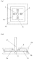
- FIG 1 is a schematic top view of a first embodiment of the invention.
- Figure 2 is a side view of the embodiment shown in Figure 1 .
- the control device according to the invention comprises a rigid base 1b and a tilting area 1a which adapted to move relative to the rigid base 1b upon exertion of a force thereto.
- Rigid in this respect means that the base 1 b is provided unmoveable with respect to the tilting area 1a.
- a hinge unit 1c connecting the tilting area 1 a to the rigid base 1 b.
- the hinge unit 1 c allows the deflection of the tilting area 1 a with respect to the rigid base 1 b.
- the control device, the rigid base 1 b, the tilting area 1 a and the hinge unit 1 c are in the embodiment shown all of rectangular shape but can have different shapes as well, like e.g. circular.
- an input unit 2 connected to the tilting area 1a to apply a force to the tilting area 1 a, and at least one sensor element 3 provided to detect a movement of the tilting area 1 a.
- the tilting area 1a is provided surrounded by the hinge unit 1c which again is surrounded by the rigid base 1 b.
- a sensor element 3 is provided to detect the movement of the tilting area 1a.
- four sensor elements 3 are provided.
- Two sensor elements 3 are provided left and right of the input unit 2, i.e. along the positive and negative x-direction.
- Two further sensor elements 3 are provided on the upper and lower side of the input unit 2, i.e. along the positive and negative y-direction as shown in Figure 1 .
- the invention is not limited to the use of four sensor elements 3.
- fewer or more sensor elements 3 may be provided.
- the sensor elements 3 are exemplarily and not restrictively provided below a top surface of a suspension element 10 of the control device and on top of the tilting area 1 a.
- the sensor elements 3 are exemplarily adapted to measure a pressing force resulting from a movement of the tilting area 1 a.
- the sensor elements 3 are not restricted thereby and can have different functionality.
- the rigid base 1 b and the tilting area 1 a extend in the same plane when no force is applied to the input unit 2.
- the support element 4 below the tilting area 1a is only an optional element. It supports the tilting area 1a. This provides stability and further also allows the provision of a counterforce against a pressing action in the z-direction of the input unit 2.
- the input unit 2 could be provided as a pressing knob or stick and the pressing of the knob or stick along the z-direction can thus be detected. Without the optional support element 4, this pressing action may not be detectable.
- the control device may comprise a suspension element 10.
- the suspension element 10 may have a rectangular shape with a top surface 11, a bottom surface 12 and two side surfaces 13 and may be hollow. On its top surface 11, a hole 14 may be provided to allow the input unit 2 to extend therethrough.
- the suspension element 10 may also be described to have the shape of a rectangular letter "C" lying on its back.
- the suspension element is shown as a separate element, but it or its parts can also be integrally formed by the surrounding housing where the control device is built into.
- the tilting area 1a in Figures 1-3 extends in parallel to the top and the bottom surface of the suspension element 10 within the suspension element 10.
- the hinge units 1c are coupled to the rigid base 1b.
- the rigid base 1b is rigidly connected to the suspension element 10.
- the rigid base 1b is fixed or pressed between side walls 14 of the suspension element 10.
- the rigid base 1 b may not be a separate element but may be an integral part of the suspension element 10 itself. In some embodiments described later, the rigid base 1 b could also be provided by the top surface 11 of the suspension element 10.
- Figure 3 shows the control element of the first embodiment in an actuated state.
- a force or an action applied perpendicular, angled or parallel to the axis of the input unit 2 as indicated by the arrow creates a possible relative movement of the tilting area 1 a towards the rigid base 1 b.
- the hinge unit 1 c allows by its given stiffness or flexibility according to its shape and/or material a deflection, movement or tilt of the tilting area 1 a towards the rigid base 1b.
- the hinge unit 1c may be biased against the tilting area 1 a and creates a counterforce once deflection or force is applied to the Input unit 2.
- the resulting movement of the tilting area 1a can have an x,y, or z axis direction or any combination of those.
- the sensor element 3 picks up the movement or force of the tilting area 1a towards the rigid base 1b and translates the primary physical values like travel resulting from a movement and/or pressure into an output signal. Once the action disappears, the tension respectively the counterforce lets the tilting area 1a return to its zero position as long as no lock state is provided by auxiliary mechanical elements as described later.
- the tilting area 1a, the rigid base 1 b and the hinge unit 1 c are integrally formed of the same material thus constituting one single integrally formed element extending in a single plane.
- the single element may be formed from PCB (printed circuit board), plastics, steel, ceramics etc. However, other materials are also possible.
- PCB printed circuit board
- the control element formed thereby is very robust and long-life.
- the stiffness or flexibility of the hinge unit 1 c can be defined by its geometry or shape of this section.
- the hinge unit 1 c may have a meander shape or may be s-shaped.
- the control element could be formed by 3D printing.
- the invention may use a single element, for instance a PCB element, where the input unit 2 is mounted onto the tilting area 1 a being movable towards the rigid base 1 c of the same PCB.
- the hinge unit 1c between those areas - also consisting of the same PCB - creates by its shape an elastic suspension of the movable part of PCB. Both areas - movable and fixed ones - can accommodate any sensor element 3 to pick up the relative movement between movable and fixed parts of the PCB.
- the input unit 2 can also be part of an additional input element like e.g. a potentiometer being mounted onto tilting area 1a, thus allowing a combined interaction of control activities during operation. This interaction may be a pushing of the input unit 2 into one direction (+-x, +-y or combination thereof) and turning the input unit 2 around its own axis.
- the input unit 2 can be any input element having at least one mode of intrinsic operation.
- the tilting area 1a is can either be in the center or the outer area of the rigid base 1b.
- the input unit 2, a lever, knob, etc. can be rigidly assembled to the center area of the control device and then the surrounding outer area becomes fixed. It also can be assembled to the outer area then the center area of the control device becomes fixed.
- Needed wires to any electrical sensor element 3 can also be fed from the sensor element 3 to an electronic circuitry using the hinge unit 1c without the need of additional cabling.
- FIG. 5 is a schematic top view of a third embodiment of the invention.
- Figure 6 is a schematic side view of the third embodiment of the invention.
- the tilting area 1a, the rigid base 1b and the hinge unit 1c are formed of different materials with respect to each other.
- the tilting area 1a, a rigid base 1 b and hinge unit 1c all have a rectangular shape.
- the tilting area 1 a is provided surrounded by the hinge unit 1 c which again is surrounded by the rigid base 1 b.
- the tilting area 1a and the rigid base 1b extend in the same plane while the hinge unit 1 c is provided coupled to the lower surfaces of the rigid base 1 b and the tilting area 1 a.
- the rigid base 1 b and the suspension element 10 may be made of plastic, the tilting area 1 a may be formed by a steel plate, and the hinge unit 1c may be a rubber cushion. However, other materials are also possible.
- the hinge unit 1c can also be coupled to the upper surface of rigid base 1 b and tilting area 1 a or upper surface of rigid base 1 a and lower surface of tilting area 1 b and vice versa.
- the tilting area 1a and the rigid base 1b are formed of same material while the hinge unit 1c is formed of a different material.
- the hinge unit 1c may comprise springs or rubber cushions etc. However, other materials/elements are also possible.
- four springs are provided along the positive and the negative x-axis and the positive and the negative y-axis.
- four sensor elements 3 are provided along the positive and the negative x-axis and the positive and the negative y-axis.
- the embodiment is not limited thereto.
- the hinge unit 1c may be provided by the sensor element 3 itself.
- the tilting area 1 a is supported on a support element 4.
- a gap is formed between the rigid base 1 b and the tilting area 1 a where in figure 1 the hinge unit 1 c was provided.
- the tilting area 1 a may be guided by vertical extensions 15 from the top surface 11 of the suspension element 10.
- the elastic suspension and counterforce is provided by the sensor element 3 itself which may be a spring based tact switch in coaction with the support element 4.
- FIG. 9 is a schematic side view of a sixth embodiment of the invention.
- the tilting area 1a was provided around the input unit 2 and was surrounded itself by the rigid base, here, the rigid base 1 b is located below the tilting area 1 a, which still surrounds the input unit 2.
- the rigid base 1b is coupled to the bottom surface 12 of the suspension element 10.
- the bottom surface 12 of the suspension element 10 may be provided with a support element 4 to support the rigid base 1b.
- the hinge unit 1c is placed exemplarily on the same plane as the rigid base 1 b and couples the rigid base 1 b to the tilting area 1a.
- FIG 10 the same embodiment is shown in which a force is applied to the input unit 2 such that the tilting area 1 a is tilted with respect to the rigid base 1b placed below the tilting area 1a and the sensor 3 is activated due to its motion towards the suspension element 10.
- the sensor 3 is a pressing switch.
- any other sensor element can be provided.
- Figure 11 is a schematic side view of a seventh embodiment of the invention.
- the input unit 2 itself can provide an additional grade of actuation. This may be provided by an encoder or a potentiometer or any input element having at least one mode of intrinsic operation.
- the input unit 2 may detect a downward pressing force onto its top surface, which could be used for a selection of an element in a menu.
- a support element 4 is provided below the tilting area 1 a. If the input unit 2 is a potentiometer, also a rotation of the input unit 2 around its axis can be detected.
- the control device is multifunctional.
- a sensor element 3 forms thus also part of the input unit 2 itself.
- Figure 12 is a schematic side view of an eighth embodiment of the invention.
- the input unit 2 in the embodiment shown can also pick up indirect actuation which may result from acceleration, vibration of a mechanical element 20 placed on top of the input unit 2.
- the input unit 2 is not directly accessible by a user.
- Figure 13 is a schematic side view of an ninth embodiment of the invention.
- a restriction element 5 is provided in a direction path of movement of the input unit 2 or the tilting area 1 a.
- the restriction element 5 is provided adjacent to the input unit 2 and is provided in the example shown to extend in the horizontal direction.
- the restriction element 5 is located on the top surface 11 of the suspension element 10, but could also be formed below the top surface 11 of the suspension element 10.
- the restriction element 5 is provided to restrict possible deflections in one direction. This is done in the embodiment shown by narrowing the hole 14 formed on the top surface 11 of suspension element 10 into which the input unit 2 is inserted. This allows to provide a restriction in one direction which may be necessary for a specific application of the inventive control device.
- the restriction element 5 could also be provided to restrict the movement of the tilting area 1 a.
- the restriction element 5 may vertically extend from the top or bottom surface 11, 12 of the suspension element 10.
- the exemplarily provided restriction element 5 of figure 13 fully restricts the movement in the positive x-direction. Therefore, a corresponding sensor element 3 may be omitted as shown in figure 13 .
- Figure 14 is a schematic side view of a tenth embodiment of the invention.
- An auxiliary or locking element 6 is provided attached to the inner bottom surface 12 of the suspension element 10 and also on the bottom surface of the tilting area 1 a.
- the auxiliary element 6 in the embodiment shown may be formed of magnetic elements.
- the magnet 6a on the tilting area 1 a locks with the magnet 6b of the suspension element 10. This locking may be overcome by an increased force applied to the input unit 2.
- the locking effect allows an output of a constant output signal for a certain time as long as the lock is not interrupted.
- FIG. 15 is a schematic side view of an eleventh embodiment of the invention.
- a haptic feedback element 7 is provided to apply a haptic feedback for the selected activity direction. This could be a detent or a multi-step detent.
- the haptic feedback element 7 of figure 15 consists of two parts, an extension element 7a extending from the tilting area 1a and having a protrusion and an interlocking element 7b with a plurality of indentations provided to interlock with the protrusion of the extension element 7a.
- the interlocking effect depends on the tilt of the tilting area 1 a and the protrusion may move from one indentation to the other along the path of movement of the tilting area 1 a providing a haptic feedback of detents.
- Figure 16 is a schematic side view of a twelfth embodiment of the invention.
- the restriction element 8 is provided to allow a certain movement in one direction, but to provide a restriction in that direction beyond the allowable movement. This may provide a protection or limitation of an impact for the tilting area 1a and/or the sensor element 3 in case of applying an extensive force or deflection to the input unit 2.
- the restriction element 8 does not fully restrict the movement in one direction. Therefore, a corresponding sensor element 3 is still provided.
- Figure 17 is a schematic side view of a thirteenth embodiment of the invention.
- An auxiliary element 9 can provide an active acknowledgement of an executed action like optical or mechanical indicators/actuators from the control device where the actuation information is fed to a separate element.
- the sensor element 3 may be provided to translate an applied action or force by a proximity detection, i.e. contactless. This may be based on an optical, magnetic, capacitive, inductive, resistive detection or by voltage and current transducers.
- the sensor element 3 may alternatively translate an applied action by a pressure or force detection.
- a spring activated switch could be used.
- the sensor element 3 may translate and applied action by a tension detection in form of a strain gauge.
- the sensor element 3 may also provide partial or full functionality of a hinge unit 1 c as shown in Figure 8 . This may be implemented by a counterforce of pressed switch, which removes the full or partial need for an additional hinge unit 1 c.
- sensor elements 3 can be located on at least one of the following elements: the tilting area 1 a, the rigid base 1 b, the hinge unit 1 c or the input unit 2 picking up any tension, travel or shift among the respective adjacent elements.
- the invention has a number of benefits compared to prior art.
- the inventive control device has high reliability resulting from a frictionless suspension and/or a frictionless translation of force / deflection to the sensor elements by a usage of contactless sensor elements.
- the control device provides extreme climatic ruggedness against dust, dirt, humidity, temperature by a possible selection of corresponding materials, a frictionless suspension, a frictionless translation of force / deflection to sensor elements and the usage of contactless sensor element.
- a flexible application of multiple grades of directed action by a combination of parts of a singular function like potentiometers, switches to an element having multi-action either separate or as a combination is provided by the inventive control device.
- the invention is cost efficient by a usage of standard materials and components like encoders, switches and a few additional manufacturing processes.
Landscapes
- Physics & Mathematics (AREA)
- General Physics & Mathematics (AREA)
- Engineering & Computer Science (AREA)
- Automation & Control Theory (AREA)
- Position Input By Displaying (AREA)
Abstract
Description
- The present invention relates generally to a control device.
- Multifunctional and direction control devices or actuators like joysticks can be used, e.g. to allow browsing and entering a selection in a menu list. They are used within electrical devices and mostly consist of a lever, which picks up the action executed by the user and feeds this movement or pressing action towards a sensor. The sensor acts like a switch and an transmission element like a rocker if further provided. Due to space and cost constraints, the application flexibility of those designs is limited. As long as friction within a hinge appears, the lifetime of the purely mechanical construction is also limited.
- In accordance with one aspect of the present invention there is provided a control device comprising a rigid base, a tilting area adapted to move relative to the rigid base upon exertion of a force thereto, a hinge unit connecting the tilting area to the rigid base, an input unit connected to the tilting area to apply a force to the tilting area, and at least one sensor element provided to detect a movement of the tilting area.
- The invention thus provides a tilting area and a fixed area, the rigid base, and a hinge unit in between. Accordingly, a force applied to the input unit creates a relative movement of the tilting area with respect to the rigid base or any elements associated with the rigid base. The hinge unit allows by its stiffness and/or flexibility, which can be adjusted by its shape and its material, a deflection of tilting area towards rigid base. The sensor element picks up the movement from the tilting area with respect to the rigid base and translates the primary effected physical values like travel resulting from the movement and/or pressure into an output signal.
- The invention allows the formation of a simple and easy to manufacture and cost efficient control element. Also, a distinctive determination of multiple grades of a directed action is possible due to the simple application of a mechanical path of the tilting area.
- The resulting movement can have x,y,z axis direction or any combination of those.
- The input unit is preferably mounted or fixed to the tilting area.
- Preferably, the rigid base extends in a first plane and the tilting area is provided to extend in parallel to or within the first plane in a situation where no force is exerted on the tilting area. Upon exertion of a force thereto the tilting area is adapted to be tilted with respect to the first plane and then extends in a second plane not parallel to the first plane.
- A suspension element may be provided to suspend the combination of the rigid base, the tilting area and the hinge unit.
- Preferably, the tilting area, the rigid base and the hinge unit are integrally formed with each other and are formed of the same material. This allows the so formed integral unit to be the carrier for the input unit while at the same time providing an elastic suspension for a directional operation of the input unit. Only one single element is needed to provide these functions. This element can be easily and cost-effectively formed. Moreover, by its integrated provision, the hinge unit is provided frictionless. The resulting control device is highly reliable due to its frictionless suspension and its frictionless translation of force or deflection to sensors. Also, the device is rugged with respect to extreme climatic environments like dust, dirt, humidity or temperature due to a selection of specific materials and the frictionless suspension, and frictionless translation of force and/or deflection to the sensor element
- Further, also sensors delivering electrical values may be used and may be formed contactless thereby further improving the reliability and ruggedness.
- The tilting area, the rigid base and the hinge unit may be formed of steel, stainless steel, ceramics, PCB (printed circuit board) or plastic. This formation of the tilting area, the rigid base and the hinge unit as a single element out of one material, standard materials can be used and even three-dimensional printing can be used to form these integrated elements.
- In another embodiment, the tilting area, and the rigid base are formed of the same material like for instance steel, ceramics or plastic and the hinge unit is formed of a different material like for instance rubber.
- The hinge unit is preferably shaped such that a predetermined flexibility of the hinge unit is obtained. Thus, through the shape and/or material of the hinge unit, its flexibility can be defined. The hinge unit may be s-shaped, or meander like shaped or can have any other shape.
- Preferably, the hinge unit provides a bias force to the tilting area. Thus, the hinge unit creates a counterforce once deflection or a force is applied to the input unit. Once an action disappears, the tension respectively the counterforce lets the tilting area return to its zero position as long as no locking state is provided by any auxiliary mechanical elements.
- In one embodiment, the hinge unit is provided by the sensor elements itself adapted to be pressed or moved upon exertion of a force thereto. This allows an even simpler construction of the control device.
- In one embodiment, the rigid base is formed of plastic and the tilting area is formed of steel, or vice versa.
- The input unit may be a joystick.
- The input unit may an encoder or a potentiometer or any other input element having at least one mode of intrinsic operation. This allows the application of even more functions to the control device.
- In one embodiment, a support element is further provided to support the tilting area. The tilting area moves relative to the support element. The support element may however also be part of the tilting area or attached thereto and may move together with the tilting area with respect to the rigid base or the suspension element. The support element or parts of it may however also be formed by the surrounding housing of the apparatus, where the control device is liked to be included into.
- The sensor element may be an optical, magnetic, capacitive, inductive, resistive sensor element or a voltage and current transducer.
- The sensor element translates an applied force by pressure/force or tension detection into an output signal.
- The sensor element may be located on any of the tilting area, the rigid base, or the input unit sensing different movements.
- In one embodiment, the sensor element forms part of the input unit.
- Further, a restriction element may be provided to restrict movement of the tilting area in at least one of the possible directions of movement. According to the invention, the desired grades of freedom of the resulting movement can be restricted, which may be desirable for certain applications.
- In another embodiment, an auxiliary element can be provided connectable to the tilted area to lock the control device in at least one direction.
- In a further embodiment, a haptic feedback element can be provided connectable to the tilted area to provide a haptic feedback of movement of the tilting area.
- The characteristics, features and advantages of this invention and the manner in which they are obtained as described above, will become more apparent and be more clearly understood in connection with the following description of exemplary embodiments, which are explained with reference to the accompanying drawings.
- In the drawings, same element numbers indicate same elements in each of the views:
-
Figure 1 is a schematic top view of a first embodiment of the invention; -
Figure 2 is a schematic side view of the first embodiment shown inFigure 1 ; -
Figure 3 is a schematic side view of the first embodiment in an actuated state; -
Figure 4 is a schematic top view of second embodiment of the invention; -
Figure 5 is a schematic top view of a third embodiment of the invention; -
Figure 6 is a schematic side view of the third embodiment of the invention; -
Figure 7 is a schematic top view of a fourth embodiment of the invention; -
Figure 8 is a schematic side view of a fifth embodiment of the invention; -
Figure 9 is a schematic side view of a sixth embodiment of the invention; -
Figure 10 is a schematic side view of the sixth embodiment in an actuated state; -
Figure 11 is a schematic side view of a seventh embodiment of the invention; -
Figure 12 is a schematic side view of an eighth embodiment of the invention; -
Figure 13 is a schematic side view of an ninth embodiment of the invention; -
Figure 14 is a schematic side view of a tenth embodiment of the invention; -
Figure 15 is a schematic side view of an eleventh embodiment of the invention; -
Figure 16 is a schematic side view of a twelfth embodiment of the invention; -
Figure 17 is a schematic side view of a thirteenth embodiment of the invention; - Throughout the following, a control device will be described. The control device is adapted to detect a movement of its input device along the x, y, z-axis or any combination of those. The control device translates a directed activity of a user to an input unit like turning a knob, stick etc. into an electrical value related to direction of activity.
-
Figure 1 is a schematic top view of a first embodiment of the invention.Figure 2 is a side view of the embodiment shown inFigure 1 . The control device according to the invention comprises arigid base 1b and atilting area 1a which adapted to move relative to therigid base 1b upon exertion of a force thereto. Rigid in this respect means that thebase 1 b is provided unmoveable with respect to thetilting area 1a. Further provided is ahinge unit 1c connecting thetilting area 1 a to therigid base 1 b. Thehinge unit 1 c allows the deflection of thetilting area 1 a with respect to therigid base 1 b. The control device, therigid base 1 b, the tiltingarea 1 a and thehinge unit 1 c are in the embodiment shown all of rectangular shape but can have different shapes as well, like e.g. circular. - Further provided is an
input unit 2 connected to thetilting area 1a to apply a force to thetilting area 1 a, and at least onesensor element 3 provided to detect a movement of thetilting area 1 a. Around theinput unit 2, the tiltingarea 1a is provided surrounded by thehinge unit 1c which again is surrounded by therigid base 1 b. - A
sensor element 3 is provided to detect the movement of thetilting area 1a. In the first embodiment, foursensor elements 3 are provided. Twosensor elements 3 are provided left and right of theinput unit 2, i.e. along the positive and negative x-direction. Twofurther sensor elements 3 are provided on the upper and lower side of theinput unit 2, i.e. along the positive and negative y-direction as shown inFigure 1 . The invention, however, is not limited to the use of foursensor elements 3. According to the desired functionality of the control device, fewer ormore sensor elements 3 may be provided. Thesensor elements 3 are exemplarily and not restrictively provided below a top surface of asuspension element 10 of the control device and on top of thetilting area 1 a. Here, thesensor elements 3 are exemplarily adapted to measure a pressing force resulting from a movement of thetilting area 1 a. However, thesensor elements 3 are not restricted thereby and can have different functionality. - In the first embodiment of
Figure 1 and 2 , therigid base 1 b and thetilting area 1 a extend in the same plane when no force is applied to theinput unit 2. Thesupport element 4 below the tiltingarea 1a is only an optional element. It supports thetilting area 1a. This provides stability and further also allows the provision of a counterforce against a pressing action in the z-direction of theinput unit 2. Theinput unit 2 could be provided as a pressing knob or stick and the pressing of the knob or stick along the z-direction can thus be detected. Without theoptional support element 4, this pressing action may not be detectable. - The control device may comprise a
suspension element 10. Thesuspension element 10 may have a rectangular shape with atop surface 11, abottom surface 12 and twoside surfaces 13 and may be hollow. On itstop surface 11, ahole 14 may be provided to allow theinput unit 2 to extend therethrough. Thesuspension element 10 may also be described to have the shape of a rectangular letter "C" lying on its back. Here, the suspension element is shown as a separate element, but it or its parts can also be integrally formed by the surrounding housing where the control device is built into. - The tilting
area 1a inFigures 1-3 extends in parallel to the top and the bottom surface of thesuspension element 10 within thesuspension element 10. On both its lateral ends, thehinge units 1c are coupled to therigid base 1b. Therigid base 1b is rigidly connected to thesuspension element 10. In the embodiment shown, therigid base 1b is fixed or pressed betweenside walls 14 of thesuspension element 10. However, therigid base 1 b may not be a separate element but may be an integral part of thesuspension element 10 itself. In some embodiments described later, therigid base 1 b could also be provided by thetop surface 11 of thesuspension element 10. -
Figure 3 shows the control element of the first embodiment in an actuated state. A force or an action applied perpendicular, angled or parallel to the axis of theinput unit 2 as indicated by the arrow creates a possible relative movement of thetilting area 1 a towards therigid base 1 b. Thehinge unit 1 c allows by its given stiffness or flexibility according to its shape and/or material a deflection, movement or tilt of thetilting area 1 a towards therigid base 1b. Thehinge unit 1c may be biased against the tiltingarea 1 a and creates a counterforce once deflection or force is applied to theInput unit 2. The resulting movement of thetilting area 1a can have an x,y, or z axis direction or any combination of those. Thesensor element 3 picks up the movement or force of thetilting area 1a towards therigid base 1b and translates the primary physical values like travel resulting from a movement and/or pressure into an output signal. Once the action disappears, the tension respectively the counterforce lets the tiltingarea 1a return to its zero position as long as no lock state is provided by auxiliary mechanical elements as described later. - In a preferred embodiment of the invention as shown in
Figure 4 , the tiltingarea 1a, therigid base 1 b and thehinge unit 1 c are integrally formed of the same material thus constituting one single integrally formed element extending in a single plane. The single element may be formed from PCB (printed circuit board), plastics, steel, ceramics etc. However, other materials are also possible. This allows a simple and cost effective manufacturing of the control device according to the invention. Furthermore, the control element formed thereby is very robust and long-life. Advantageously, the stiffness or flexibility of thehinge unit 1 c can be defined by its geometry or shape of this section. Thehinge unit 1 c may have a meander shape or may be s-shaped. In this embodiment, the control element could be formed by 3D printing. - Thus, the invention may use a single element, for instance a PCB element, where the
input unit 2 is mounted onto the tiltingarea 1 a being movable towards therigid base 1 c of the same PCB. - The
hinge unit 1c between those areas - also consisting of the same PCB - creates by its shape an elastic suspension of the movable part of PCB. Both areas - movable and fixed ones - can accommodate anysensor element 3 to pick up the relative movement between movable and fixed parts of the PCB. Theinput unit 2, as will be later described, can also be part of an additional input element like e.g. a potentiometer being mounted onto tiltingarea 1a, thus allowing a combined interaction of control activities during operation. This interaction may be a pushing of theinput unit 2 into one direction (+-x, +-y or combination thereof) and turning theinput unit 2 around its own axis. Theinput unit 2 can be any input element having at least one mode of intrinsic operation. - Throughout the invention, the tilting
area 1a is can either be in the center or the outer area of therigid base 1b. Thus, theinput unit 2, a lever, knob, etc. can be rigidly assembled to the center area of the control device and then the surrounding outer area becomes fixed. It also can be assembled to the outer area then the center area of the control device becomes fixed. - Needed wires to any
electrical sensor element 3 can also be fed from thesensor element 3 to an electronic circuitry using thehinge unit 1c without the need of additional cabling. -
Figure 5 is a schematic top view of a third embodiment of the invention.Figure 6 is a schematic side view of the third embodiment of the invention. InFigure 5 and Figure 6 , the tiltingarea 1a, therigid base 1b and thehinge unit 1c are formed of different materials with respect to each other. In the top view shown inFigure 5 , the tiltingarea 1a, arigid base 1 b and hingeunit 1c all have a rectangular shape. Around theinput unit 2, the tiltingarea 1 a is provided surrounded by thehinge unit 1 c which again is surrounded by therigid base 1 b. In the side view ofFigure 6 it is visible that thetilting area 1a and therigid base 1b extend in the same plane while thehinge unit 1 c is provided coupled to the lower surfaces of therigid base 1 b and thetilting area 1 a. Therigid base 1 b and thesuspension element 10 may be made of plastic, the tiltingarea 1 a may be formed by a steel plate, and thehinge unit 1c may be a rubber cushion. However, other materials are also possible. However, thehinge unit 1c can also be coupled to the upper surface ofrigid base 1 b and tiltingarea 1 a or upper surface ofrigid base 1 a and lower surface of tiltingarea 1 b and vice versa. - In the fourth embodiment of
Figure 7 , the tiltingarea 1a and therigid base 1b are formed of same material while thehinge unit 1c is formed of a different material. Thehinge unit 1c may comprise springs or rubber cushions etc. However, other materials/elements are also possible. In the embodiment shown inFigure 7 , four springs are provided along the positive and the negative x-axis and the positive and the negative y-axis. Also, foursensor elements 3 are provided along the positive and the negative x-axis and the positive and the negative y-axis. However, the embodiment is not limited thereto. - In another embodiment a shown in
Figure 8 thehinge unit 1c may be provided by thesensor element 3 itself. The tiltingarea 1 a is supported on asupport element 4. In a plane of thetilting area 1 a, a gap is formed between therigid base 1 b and thetilting area 1 a where infigure 1 thehinge unit 1 c was provided. The tiltingarea 1 a may be guided byvertical extensions 15 from thetop surface 11 of thesuspension element 10. In the embodiment shown, the elastic suspension and counterforce is provided by thesensor element 3 itself which may be a spring based tact switch in coaction with thesupport element 4. -
Figure 9 is a schematic side view of a sixth embodiment of the invention. Whereas in the previous embodiments, the tiltingarea 1a was provided around theinput unit 2 and was surrounded itself by the rigid base, here, therigid base 1 b is located below the tiltingarea 1 a, which still surrounds theinput unit 2. Therigid base 1b is coupled to thebottom surface 12 of thesuspension element 10. Here, thebottom surface 12 of thesuspension element 10 may be provided with asupport element 4 to support therigid base 1b. Thehinge unit 1c is placed exemplarily on the same plane as therigid base 1 b and couples therigid base 1 b to thetilting area 1a. InFigure 10 , the same embodiment is shown in which a force is applied to theinput unit 2 such that thetilting area 1 a is tilted with respect to therigid base 1b placed below the tiltingarea 1a and thesensor 3 is activated due to its motion towards thesuspension element 10. In the provided embodiment, thesensor 3 is a pressing switch. However, any other sensor element can be provided. -
Figure 11 is a schematic side view of a seventh embodiment of the invention. With respect to the first embodiment, only theinput unit 2 is different. Theinput unit 2 itself can provide an additional grade of actuation. This may be provided by an encoder or a potentiometer or any input element having at least one mode of intrinsic operation. Theinput unit 2 may detect a downward pressing force onto its top surface, which could be used for a selection of an element in a menu. In order to provide a counterforce against the pressing force, asupport element 4 is provided below the tiltingarea 1 a. If theinput unit 2 is a potentiometer, also a rotation of theinput unit 2 around its axis can be detected. Thus, the control device is multifunctional. In this embodiment, asensor element 3 forms thus also part of theinput unit 2 itself. -
Figure 12 is a schematic side view of an eighth embodiment of the invention. Theinput unit 2 in the embodiment shown can also pick up indirect actuation which may result from acceleration, vibration of amechanical element 20 placed on top of theinput unit 2. In this embodiment, theinput unit 2 is not directly accessible by a user. -
Figure 13 is a schematic side view of an ninth embodiment of the invention. InFigure 13 , arestriction element 5 is provided in a direction path of movement of theinput unit 2 or thetilting area 1 a. Exemplarily, therestriction element 5 is provided adjacent to theinput unit 2 and is provided in the example shown to extend in the horizontal direction. Therestriction element 5 is located on thetop surface 11 of thesuspension element 10, but could also be formed below thetop surface 11 of thesuspension element 10. Therestriction element 5 is provided to restrict possible deflections in one direction. This is done in the embodiment shown by narrowing thehole 14 formed on thetop surface 11 ofsuspension element 10 into which theinput unit 2 is inserted. This allows to provide a restriction in one direction which may be necessary for a specific application of the inventive control device. Therestriction element 5 could also be provided to restrict the movement of thetilting area 1 a. Here, therestriction element 5 may vertically extend from the top orbottom surface suspension element 10. The exemplarily providedrestriction element 5 offigure 13 fully restricts the movement in the positive x-direction. Therefore, a correspondingsensor element 3 may be omitted as shown infigure 13 . -
Figure 14 is a schematic side view of a tenth embodiment of the invention. An auxiliary or lockingelement 6 is provided attached to theinner bottom surface 12 of thesuspension element 10 and also on the bottom surface of thetilting area 1 a. Theauxiliary element 6 in the embodiment shown may be formed of magnetic elements. Upon movement of thetilting area 1 a, themagnet 6a on thetilting area 1 a locks with themagnet 6b of thesuspension element 10. This locking may be overcome by an increased force applied to theinput unit 2. The locking effect allows an output of a constant output signal for a certain time as long as the lock is not interrupted. -
Figure 15 is a schematic side view of an eleventh embodiment of the invention. Ahaptic feedback element 7 is provided to apply a haptic feedback for the selected activity direction. This could be a detent or a multi-step detent. Thehaptic feedback element 7 offigure 15 consists of two parts, anextension element 7a extending from the tiltingarea 1a and having a protrusion and an interlockingelement 7b with a plurality of indentations provided to interlock with the protrusion of theextension element 7a. The interlocking effect depends on the tilt of thetilting area 1 a and the protrusion may move from one indentation to the other along the path of movement of thetilting area 1 a providing a haptic feedback of detents. -
Figure 16 is a schematic side view of a twelfth embodiment of the invention. InFigure 16 , therestriction element 8 is provided to allow a certain movement in one direction, but to provide a restriction in that direction beyond the allowable movement. This may provide a protection or limitation of an impact for thetilting area 1a and/or thesensor element 3 in case of applying an extensive force or deflection to theinput unit 2. In contrast tofigure 13 , therestriction element 8 does not fully restrict the movement in one direction. Therefore, a correspondingsensor element 3 is still provided. -
Figure 17 is a schematic side view of a thirteenth embodiment of the invention. Anauxiliary element 9 can provide an active acknowledgement of an executed action like optical or mechanical indicators/actuators from the control device where the actuation information is fed to a separate element. - In the embodiments shown, the
sensor element 3 may be provided to translate an applied action or force by a proximity detection, i.e. contactless. This may be based on an optical, magnetic, capacitive, inductive, resistive detection or by voltage and current transducers. Thesensor element 3 may alternatively translate an applied action by a pressure or force detection. Here, a spring activated switch could be used. Further, thesensor element 3 may translate and applied action by a tension detection in form of a strain gauge. - The
sensor element 3 may also provide partial or full functionality of ahinge unit 1 c as shown inFigure 8 . This may be implemented by a counterforce of pressed switch, which removes the full or partial need for anadditional hinge unit 1 c. - Throughout the invention,
sensor elements 3 can be located on at least one of the following elements: the tiltingarea 1 a, therigid base 1 b, thehinge unit 1 c or theinput unit 2 picking up any tension, travel or shift among the respective adjacent elements. - The invention has a number of benefits compared to prior art.
- The inventive control device has high reliability resulting from a frictionless suspension and/or a frictionless translation of force / deflection to the sensor elements by a usage of contactless sensor elements.
- The control device provides extreme climatic ruggedness against dust, dirt, humidity, temperature by a possible selection of corresponding materials, a frictionless suspension, a frictionless translation of force / deflection to sensor elements and the usage of contactless sensor element.
- Further, a distinctive detection of multiple grades of directed action by the application of a mechanical path of the tilting area is feasible.
- A flexible application of multiple grades of directed action by a combination of parts of a singular function like potentiometers, switches to an element having multi-action either separate or as a combination is provided by the inventive control device.
- Further, the invention is cost efficient by a usage of standard materials and components like encoders, switches and a few additional manufacturing processes.
- It should be understood that the embodiments shown may also be combined if not excluded otherwise.
- While this invention has been described in connection with what is presently considered to be practical exemplary embodiments, it is to be understood that the invention is not limited to the disclosed embodiments, but, on the contrary, is intended to cover various modifications and equivalent arrangements included within the scope of the appended claims.
-
- 1a
- tilting area
- 1b
- rigid base
- 1c
- hinge unit
- 2
- input unit
- 3
- sensor element
- 4
- support element
- 5,8
- restriction element
- 6,9
- auxiliary element
- 7
- haptic feedback element
- 7a
- extension element
- 7b
- interlocking element
- 10
- suspension element
- 11
- top surface of suspension element
- 12
- bottom surface of suspension element
- 13
- side surface of suspension element
- 14
- hole in suspension element
- 15
- vertical extensions of suspension element
- 20
- mechanical element
Claims (18)
- A control device comprisinga rigid base (1 b),a tilting area (1a) adapted to move relative to the rigid base (1b) upon exertion of a force thereto,a hinge unit (1c) connecting the tilting area (1a) to the rigid base (1b),an input unit (2) connected to the tilting area (1a) to apply a force to the tilting area (1 a), andat least one sensor element (3) provided to detect a movement of the tilting area (1 a).
- Control device according to claim 1, wherein the rigid base (1 b) extends in a first plane and the tilting area (1 a) is provided to extend in parallel to or within the first plane in a situation where no force is exerted on the tilting area (1 a), and upon exertion of a force thereto adapted to be tilted with respect to the first plane and to extend in a second plane not parallel to the first plane.
- Control device according to claim 1 or 2, wherein a suspension element (10) is provided to suspend the combination of the rigid base (1 b), the tilting area (1 a) and the hinge unit (1c).
- Control device according to any one of the previous claims, wherein the tilting area (1 a), the rigid base (1 b) and the hinge unit (1 c) are integrally formed with each other.
- Control device according to any one of the previous claims, wherein the tilting area (1a), the rigid base (1 b) and the hinge unit (1c) are formed of the same material, preferably of steel, stainless steel, ceramics , PCB or plastic.
- Control device according to any one of the previous claims, wherein the tilting area (1a), and the rigid base (1 b) are formed of the same material and the hinge unit (1 c) is formed of a different material.
- Control device according to any one of the previous claims, wherein the hinge unit (1 c) is shaped such that a predetermined flexibility of the hinge unit (1 c) is obtained.
- Control device according to claim 7, wherein the hinge unit (1c) is s-shaped, or has a meander like shape.
- Control device according to any one of the previous claims, wherein the hinge unit (1 c) provides a bias force to the tilting area (1 a).
- Control device according to any one of the previous claims, wherein the hinge unit (1 c) is provided by the sensor elements (2) adapted to be pressed or moved upon exertion of a force thereto.
- Control device according to any one of the previous claims, wherein the input unit (2) is:- adapted to move in at least two directions, and/or- is an encoder, a joystick, a potentiometer or any other input element having at least one mode of intrinsic operation.
- Control device according to any one of the previous claims, wherein a support element (4) is further provided to support the tilting area (1 a).
- Control device according to any one of the previous claims, wherein the sensor element (3) is a contactless proximity sensor or translates an applied force by pressure/force or tension detection into an output signal.
- Control device according to any one of the previous claims, wherein the sensor elements (3) are located on any one of the following elements: the tilting area (1 a), the rigid base (1 b), or the input unit (2).
- Control device according to any one of the previous claims, wherein the sensor elements (3) form part of the input unit (2).
- Control device according to any one of the previous claims, wherein a restriction element (5) is provided to restrict movement of the tilting area (1 a) in at least one of the possible directions of movement.
- Control device according to any one of the previous claims, wherein an auxiliary element (6) is provided connectable to the tilted area to lock the control device in at least one direction.
- Control device according to any one of the previous claims, wherein a haptic feedback element (7) is provided connectable to the tilted area to provide a haptic feedback of movement of the tilting area (1 a).
Priority Applications (1)
| Application Number | Priority Date | Filing Date | Title |
|---|---|---|---|
| EP16182600.3A EP3279761B1 (en) | 2016-08-03 | 2016-08-03 | Multifunctional control device |
Applications Claiming Priority (1)
| Application Number | Priority Date | Filing Date | Title |
|---|---|---|---|
| EP16182600.3A EP3279761B1 (en) | 2016-08-03 | 2016-08-03 | Multifunctional control device |
Publications (2)
| Publication Number | Publication Date |
|---|---|
| EP3279761A1 true EP3279761A1 (en) | 2018-02-07 |
| EP3279761B1 EP3279761B1 (en) | 2026-01-28 |
Family
ID=56883519
Family Applications (1)
| Application Number | Title | Priority Date | Filing Date |
|---|---|---|---|
| EP16182600.3A Active EP3279761B1 (en) | 2016-08-03 | 2016-08-03 | Multifunctional control device |
Country Status (1)
| Country | Link |
|---|---|
| EP (1) | EP3279761B1 (en) |
Cited By (1)
| Publication number | Priority date | Publication date | Assignee | Title |
|---|---|---|---|---|
| WO2020182864A1 (en) * | 2019-03-13 | 2020-09-17 | Leopold Kostal Gmbh & Co. Kg | Electrical multi-directional force sensor |
Citations (6)
| Publication number | Priority date | Publication date | Assignee | Title |
|---|---|---|---|---|
| US5640178A (en) * | 1994-09-16 | 1997-06-17 | Fujitsu Limited | Pointing device |
| US5714980A (en) * | 1995-10-31 | 1998-02-03 | Mitsumi Electric Co., Ltd. | Pointing device |
| EP0869343A1 (en) * | 1997-04-04 | 1998-10-07 | Matsushita Electric Industrial Co., Ltd. | Load sensor and pointing equipment incorporating the same |
| US5859372A (en) * | 1994-04-11 | 1999-01-12 | Neltoft; Peter | Device for use in manual control of the movement of a real or imaginary object |
| US6693624B1 (en) * | 1999-07-02 | 2004-02-17 | Hosiden Corporation | Joystick operated positioning device for a computer |
| DE202009016091U1 (en) * | 2009-11-20 | 2010-03-11 | Austriamicrosystems Ag | Spring and button |
-
2016
- 2016-08-03 EP EP16182600.3A patent/EP3279761B1/en active Active
Patent Citations (6)
| Publication number | Priority date | Publication date | Assignee | Title |
|---|---|---|---|---|
| US5859372A (en) * | 1994-04-11 | 1999-01-12 | Neltoft; Peter | Device for use in manual control of the movement of a real or imaginary object |
| US5640178A (en) * | 1994-09-16 | 1997-06-17 | Fujitsu Limited | Pointing device |
| US5714980A (en) * | 1995-10-31 | 1998-02-03 | Mitsumi Electric Co., Ltd. | Pointing device |
| EP0869343A1 (en) * | 1997-04-04 | 1998-10-07 | Matsushita Electric Industrial Co., Ltd. | Load sensor and pointing equipment incorporating the same |
| US6693624B1 (en) * | 1999-07-02 | 2004-02-17 | Hosiden Corporation | Joystick operated positioning device for a computer |
| DE202009016091U1 (en) * | 2009-11-20 | 2010-03-11 | Austriamicrosystems Ag | Spring and button |
Cited By (3)
| Publication number | Priority date | Publication date | Assignee | Title |
|---|---|---|---|---|
| WO2020182864A1 (en) * | 2019-03-13 | 2020-09-17 | Leopold Kostal Gmbh & Co. Kg | Electrical multi-directional force sensor |
| CN113615087A (en) * | 2019-03-13 | 2021-11-05 | 科世达汽车电气有限及两合公司 | Electronic multi-path force sensor |
| US11747221B2 (en) | 2019-03-13 | 2023-09-05 | Kostal Automobil Elektrik Gmbh & Co. Kg | Electrical multi-directional force sensor |
Also Published As
| Publication number | Publication date |
|---|---|
| EP3279761B1 (en) | 2026-01-28 |
Similar Documents
| Publication | Publication Date | Title |
|---|---|---|
| US10840041B1 (en) | Multifunctional control element | |
| EP3834061B1 (en) | Computer input devices | |
| JP3852854B2 (en) | Contact operation type input device and its electronic components | |
| EP3165997B1 (en) | Automotive input apparatus comprising a touch sensitive input device | |
| JP6301355B2 (en) | Operating device for vehicle parts | |
| EP3567462B1 (en) | Sensor device and method | |
| US20080288093A1 (en) | Joystick controller | |
| CN111527471B (en) | Input device with handle and capacitive coupling device that can be moved over the capacitive detection surface | |
| US20150009178A1 (en) | Input device comprising a touch-sensitive input surface | |
| EP1839392B1 (en) | Shared electrode pattern field effect sensor and joystick therewith | |
| JP2018018159A (en) | Input device | |
| WO2007097979A2 (en) | Systems using variable resistance zones and stops for generating inputs to an electronic device | |
| EP3279761B1 (en) | Multifunctional control device | |
| US7402764B2 (en) | Multi-functional touch actuator in electronic devices | |
| JP4800800B2 (en) | Shift operation position detection device | |
| US20030066739A1 (en) | Controller with tactile feedback | |
| CN113805692B (en) | Input device with an operating part that is mounted movably by means of a leaf spring element | |
| KR100960219B1 (en) | Haptic Switch Unit and Haptic Switch System Having Same | |
| JP7692486B2 (en) | Directional Input Devices and Controllers | |
| WO2018016600A1 (en) | Operation device | |
| CN103777808B (en) | Operating device | |
| KR102112252B1 (en) | Capacitive sensor for detecting a relative movement of two adjacent bodies | |
| KR20200041322A (en) | Force detection sensor | |
| WO2022003525A1 (en) | User interface with innovative resistive force sensor | |
| KR102711494B1 (en) | Touchpad with Vibration actuator |
Legal Events
| Date | Code | Title | Description |
|---|---|---|---|
| PUAI | Public reference made under article 153(3) epc to a published international application that has entered the european phase |
Free format text: ORIGINAL CODE: 0009012 |
|
| STAA | Information on the status of an ep patent application or granted ep patent |
Free format text: STATUS: THE APPLICATION HAS BEEN PUBLISHED |
|
| AK | Designated contracting states |
Kind code of ref document: A1 Designated state(s): AL AT BE BG CH CY CZ DE DK EE ES FI FR GB GR HR HU IE IS IT LI LT LU LV MC MK MT NL NO PL PT RO RS SE SI SK SM TR |
|
| AX | Request for extension of the european patent |
Extension state: BA ME |
|
| STAA | Information on the status of an ep patent application or granted ep patent |
Free format text: STATUS: REQUEST FOR EXAMINATION WAS MADE |
|
| 17P | Request for examination filed |
Effective date: 20180712 |
|
| RBV | Designated contracting states (corrected) |
Designated state(s): AL AT BE BG CH CY CZ DE DK EE ES FI FR GB GR HR HU IE IS IT LI LT LU LV MC MK MT NL NO PL PT RO RS SE SI SK SM TR |
|
| STAA | Information on the status of an ep patent application or granted ep patent |
Free format text: STATUS: EXAMINATION IS IN PROGRESS |
|
| 17Q | First examination report despatched |
Effective date: 20210127 |
|
| GRAP | Despatch of communication of intention to grant a patent |
Free format text: ORIGINAL CODE: EPIDOSNIGR1 |
|
| STAA | Information on the status of an ep patent application or granted ep patent |
Free format text: STATUS: GRANT OF PATENT IS INTENDED |
|
| GRAJ | Information related to disapproval of communication of intention to grant by the applicant or resumption of examination proceedings by the epo deleted |
Free format text: ORIGINAL CODE: EPIDOSDIGR1 |
|
| STAA | Information on the status of an ep patent application or granted ep patent |
Free format text: STATUS: EXAMINATION IS IN PROGRESS |
|
| INTG | Intention to grant announced |
Effective date: 20250605 |
|
| INTC | Intention to grant announced (deleted) | ||
| GRAP | Despatch of communication of intention to grant a patent |
Free format text: ORIGINAL CODE: EPIDOSNIGR1 |
|
| STAA | Information on the status of an ep patent application or granted ep patent |
Free format text: STATUS: GRANT OF PATENT IS INTENDED |
|
| INTG | Intention to grant announced |
Effective date: 20250903 |
|
| GRAS | Grant fee paid |
Free format text: ORIGINAL CODE: EPIDOSNIGR3 |
|
| GRAA | (expected) grant |
Free format text: ORIGINAL CODE: 0009210 |
|
| STAA | Information on the status of an ep patent application or granted ep patent |
Free format text: STATUS: THE PATENT HAS BEEN GRANTED |
|
| AK | Designated contracting states |
Kind code of ref document: B1 Designated state(s): AL AT BE BG CH CY CZ DE DK EE ES FI FR GB GR HR HU IE IS IT LI LT LU LV MC MK MT NL NO PL PT RO RS SE SI SK SM TR |
|
| REG | Reference to a national code |
Ref country code: CH Ref legal event code: F10 Free format text: ST27 STATUS EVENT CODE: U-0-0-F10-F00 (AS PROVIDED BY THE NATIONAL OFFICE) Effective date: 20260128 Ref country code: GB Ref legal event code: FG4D |
|
| REG | Reference to a national code |
Ref country code: DE Ref legal event code: R096 Ref document number: 602016094614 Country of ref document: DE |
|
| REG | Reference to a national code |
Ref country code: IE Ref legal event code: FG4D |