EP3279457B1 - Systems and methods for restraining exhaust gas ducts - Google Patents
Systems and methods for restraining exhaust gas ducts Download PDFInfo
- Publication number
- EP3279457B1 EP3279457B1 EP17168894.8A EP17168894A EP3279457B1 EP 3279457 B1 EP3279457 B1 EP 3279457B1 EP 17168894 A EP17168894 A EP 17168894A EP 3279457 B1 EP3279457 B1 EP 3279457B1
- Authority
- EP
- European Patent Office
- Prior art keywords
- flute
- tie
- flutes
- retainer
- coupled
- Prior art date
- Legal status (The legal status is an assumption and is not a legal conclusion. Google has not performed a legal analysis and makes no representation as to the accuracy of the status listed.)
- Active
Links
Images


Classifications
-
- B—PERFORMING OPERATIONS; TRANSPORTING
- B64—AIRCRAFT; AVIATION; COSMONAUTICS
- B64D—EQUIPMENT FOR FITTING IN OR TO AIRCRAFT; FLIGHT SUITS; PARACHUTES; ARRANGEMENT OR MOUNTING OF POWER PLANTS OR PROPULSION TRANSMISSIONS IN AIRCRAFT
- B64D29/00—Power-plant nacelles, fairings or cowlings
-
- B—PERFORMING OPERATIONS; TRANSPORTING
- B64—AIRCRAFT; AVIATION; COSMONAUTICS
- B64D—EQUIPMENT FOR FITTING IN OR TO AIRCRAFT; FLIGHT SUITS; PARACHUTES; ARRANGEMENT OR MOUNTING OF POWER PLANTS OR PROPULSION TRANSMISSIONS IN AIRCRAFT
- B64D33/00—Arrangement in aircraft of power plant parts or auxiliaries not otherwise provided for
- B64D33/04—Arrangement in aircraft of power plant parts or auxiliaries not otherwise provided for of exhaust outlets or jet pipes
-
- F—MECHANICAL ENGINEERING; LIGHTING; HEATING; WEAPONS; BLASTING
- F01—MACHINES OR ENGINES IN GENERAL; ENGINE PLANTS IN GENERAL; STEAM ENGINES
- F01N—GAS-FLOW SILENCERS OR EXHAUST APPARATUS FOR MACHINES OR ENGINES IN GENERAL; GAS-FLOW SILENCERS OR EXHAUST APPARATUS FOR INTERNAL-COMBUSTION ENGINES
- F01N13/00—Exhaust or silencing apparatus characterised by constructional features
- F01N13/08—Other arrangements or adaptations of exhaust conduits
- F01N13/082—Other arrangements or adaptations of exhaust conduits of tailpipe, e.g. with means for mixing air with exhaust for exhaust cooling, dilution or evacuation
-
- F—MECHANICAL ENGINEERING; LIGHTING; HEATING; WEAPONS; BLASTING
- F02—COMBUSTION ENGINES; HOT-GAS OR COMBUSTION-PRODUCT ENGINE PLANTS
- F02K—JET-PROPULSION PLANTS
- F02K1/00—Plants characterised by the form or arrangement of the jet pipe or nozzle; Jet pipes or nozzles peculiar thereto
- F02K1/46—Nozzles having means for adding air to the jet or for augmenting the mixing region between the jet and the ambient air, e.g. for silencing
- F02K1/48—Corrugated nozzles
-
- F—MECHANICAL ENGINEERING; LIGHTING; HEATING; WEAPONS; BLASTING
- F02—COMBUSTION ENGINES; HOT-GAS OR COMBUSTION-PRODUCT ENGINE PLANTS
- F02K—JET-PROPULSION PLANTS
- F02K1/00—Plants characterised by the form or arrangement of the jet pipe or nozzle; Jet pipes or nozzles peculiar thereto
- F02K1/78—Other construction of jet pipes
- F02K1/80—Couplings or connections
-
- B—PERFORMING OPERATIONS; TRANSPORTING
- B64—AIRCRAFT; AVIATION; COSMONAUTICS
- B64D—EQUIPMENT FOR FITTING IN OR TO AIRCRAFT; FLIGHT SUITS; PARACHUTES; ARRANGEMENT OR MOUNTING OF POWER PLANTS OR PROPULSION TRANSMISSIONS IN AIRCRAFT
- B64D33/00—Arrangement in aircraft of power plant parts or auxiliaries not otherwise provided for
- B64D33/04—Arrangement in aircraft of power plant parts or auxiliaries not otherwise provided for of exhaust outlets or jet pipes
- B64D2033/045—Arrangement in aircraft of power plant parts or auxiliaries not otherwise provided for of exhaust outlets or jet pipes comprising infrared suppressors
-
- F—MECHANICAL ENGINEERING; LIGHTING; HEATING; WEAPONS; BLASTING
- F01—MACHINES OR ENGINES IN GENERAL; ENGINE PLANTS IN GENERAL; STEAM ENGINES
- F01N—GAS-FLOW SILENCERS OR EXHAUST APPARATUS FOR MACHINES OR ENGINES IN GENERAL; GAS-FLOW SILENCERS OR EXHAUST APPARATUS FOR INTERNAL-COMBUSTION ENGINES
- F01N2590/00—Exhaust or silencing apparatus adapted to particular use, e.g. for military applications, airplanes, submarines
-
- F—MECHANICAL ENGINEERING; LIGHTING; HEATING; WEAPONS; BLASTING
- F05—INDEXING SCHEMES RELATING TO ENGINES OR PUMPS IN VARIOUS SUBCLASSES OF CLASSES F01-F04
- F05D—INDEXING SCHEME FOR ASPECTS RELATING TO NON-POSITIVE-DISPLACEMENT MACHINES OR ENGINES, GAS-TURBINES OR JET-PROPULSION PLANTS
- F05D2260/00—Function
- F05D2260/30—Retaining components in desired mutual position
-
- F—MECHANICAL ENGINEERING; LIGHTING; HEATING; WEAPONS; BLASTING
- F05—INDEXING SCHEMES RELATING TO ENGINES OR PUMPS IN VARIOUS SUBCLASSES OF CLASSES F01-F04
- F05D—INDEXING SCHEME FOR ASPECTS RELATING TO NON-POSITIVE-DISPLACEMENT MACHINES OR ENGINES, GAS-TURBINES OR JET-PROPULSION PLANTS
- F05D2260/00—Function
- F05D2260/96—Preventing, counteracting or reducing vibration or noise
-
- Y—GENERAL TAGGING OF NEW TECHNOLOGICAL DEVELOPMENTS; GENERAL TAGGING OF CROSS-SECTIONAL TECHNOLOGIES SPANNING OVER SEVERAL SECTIONS OF THE IPC; TECHNICAL SUBJECTS COVERED BY FORMER USPC CROSS-REFERENCE ART COLLECTIONS [XRACs] AND DIGESTS
- Y02—TECHNOLOGIES OR APPLICATIONS FOR MITIGATION OR ADAPTATION AGAINST CLIMATE CHANGE
- Y02T—CLIMATE CHANGE MITIGATION TECHNOLOGIES RELATED TO TRANSPORTATION
- Y02T50/00—Aeronautics or air transport
- Y02T50/60—Efficient propulsion technologies, e.g. for aircraft
Definitions
- This invention relates generally to systems and methods for restricting movement in ducts, and, more generally, to methods and systems for increasing the natural frequency of a duct.
- Exhaust systems for aircraft or other vehicles may have features that mix hot exhaust air and cooler ambient air to limit temperatures of the surrounding vehicle structure or to limit the heat signature of the vehicle.
- One method of achieving cooler exhaust temperatures is to attach a flow mixer to the outlet of the exhaust system.
- At least some known flow mixers include a plurality of lobes, or "flutes,” that promote mixing of the exhaust air and cooler ambient air.
- a potential drawback is that the stiffness of the flow mixer may be reduced because of the lobed or fluted designs. Consequently, at engine or rotor frequencies that align with the flow mixer's natural frequency, and such alignment of natural frequencies (resonance) may lead to increased deflection and stresses that may limit or prevent use of a fluted design, or may use thicker, heavier duct walls. Further, static and/or dynamic pressures on the walls of the flutes may cause large deflections in the area of the flutes and may impact flow mixing.
- Duct size and configuration of an exhaust system may also contribute to natural frequency. At least some known exhaust systems use ducts having relatively small flow mixers in an attempt to avoid certain frequencies without additional stiffening features. However, such relatively low-flow mixers may not provide optimal efficient mixing of hot exhaust air and cooler ambient air. Furthermore, at least some exhaust systems may use multiple small, relatively low-flow mixers to increase the mixing efficiency. However, multiple flow mixers may increase manufacturing costs, maintenance costs, and/or weight associated with the exhaust system.
- US 5265807A in accordance with its abstract, relates to a mixing nozzle for an aircraft turbine engine having an improved aerodynamic stiffening ring secured to the lobes of the mixer.
- Aircraft turbine engines having a rearwardly discharging nozzle are often provided with a mixer having a generally circular forward end adapted to be attached to an engine and axially deepening corrugations leading to a multi-lobed aft end surrounding the nozzle.
- This mixer mixes ambient cool air with the hot gases exiting the engine thus suppressing engine sound.
- the lobes are generally unsupported and subject to vibration and excessive deflections in use.
- a circumferential stiffening ring is secured to the aft end of the mixer to reduce or prevent the vibration while simultaneously enhancing the mixing of cool ambient air with the hot engine exhaust.
- the stiffening ring preferably has an airfoil cross-section for lowest drag combined with the ability to direct flow past the ring in a selected optimum direction.
- JPH112156 A in accordance with its abstract, relates to a lobe type mixer that comprises a pair of an upper and a lower symmetric type variable lobes opened from each other.
- Each lobe comprises plural recessed parts tapered off, and protruded parts adjacent to the recessed parts to be continuous with each other, and side surface parts are provided to compose side surfaces of the lobes so swirl to turn along flow is formed between a high speed gas flow on the inside of the lobes and an introduced air flow on the outside, where the corresponding recessed parts of the upper and lower changeable lobes are coupled with each other by a place member parallel to the flow direction.
- the system described herein includes a duct for directing a flow of exhaust, the duct including a wall portion defining a passageway having an inlet portion adapted to receive the flow of exhaust and an outlet portion adapted to discharge the flow of exhaust.
- a plurality of flutes is defined at the outlet portion, and the plurality of flutes include a first flute and a second flute spaced from the first flute.
- the first flute has a peak, a trough, a first height dimension and a first width dimension generally perpendicular to the first height dimension
- the second flute has a peak, a trough, a second height dimension and a second width dimension generally perpendicular to the second height dimension.
- Two flute ties are respectively coupled to the first trough and to the second trough.
- At least one retainer is couplec to the trough of the first flute and the trough of the second flute in addition to or instead of the at least two flute ties and extends generally parallel to at least one of the first width dimension and the second width dimension, wherein the retainer is configured to restrain relative movement between the first flute and the second flute and relative movement among the first flute, the second flute, and at least one of the inlet portion and the outlet portion during the flow of exhaust through the duct.
- a stiffener apparatus for an exhaust duct includes a first row of flutes and a second row of flutes generally opposite to the first row of flutes, and each flute is elongated along a respective axis, and the stiffener apparatus includes at least two flute ties coupling together at least two flutes from the first row of flutes to at least two flutes from the second row of flutes.
- At least one retainer is coupled to the at least two flute ties and extends generally perpendicularly to the axis of each of the at least two flutes from the first row of flutes and the at least two flutes from the second row of flutes, wherein the retainer is configured to generally restrain relative movement between the at least two flutes from the first row of flutes and the at least two flutes from the second row of flutes.
- a method for increasing the resonant frequency of an exhaust system having at least one duct, the duct including a plurality of flutes.
- Each flute includes a trough and an elongated portion with a respective axis and a lateral portion extending generally perpendicular to the respective axis, wherein the length of the elongated portion is greater than the width of the lateral portion.
- the method includes selecting a first flute from the plurality of flutes, the first flute having a first axis and selecting a second flute from the plurality of flutes, the second flute having a second axis generally parallel to the first axis.
- the retainer is oriented to extend generally perpendicular to the first and second axes, and a first portion of the retainer is coupled to the trough of the first flute and a second portion of the retainer is coupled to the trough of the second flute such that the retainer generally restrains movement between the first flute and the second flute.
Landscapes
- Engineering & Computer Science (AREA)
- Chemical & Material Sciences (AREA)
- Combustion & Propulsion (AREA)
- Mechanical Engineering (AREA)
- General Engineering & Computer Science (AREA)
- Aviation & Aerospace Engineering (AREA)
- Exhaust Silencers (AREA)
- Quick-Acting Or Multi-Walled Pipe Joints (AREA)
Description
- This invention relates generally to systems and methods for restricting movement in ducts, and, more generally, to methods and systems for increasing the natural frequency of a duct.
- Exhaust systems for aircraft or other vehicles may have features that mix hot exhaust air and cooler ambient air to limit temperatures of the surrounding vehicle structure or to limit the heat signature of the vehicle. One method of achieving cooler exhaust temperatures is to attach a flow mixer to the outlet of the exhaust system. At least some known flow mixers include a plurality of lobes, or "flutes," that promote mixing of the exhaust air and cooler ambient air.
- A potential drawback is that the stiffness of the flow mixer may be reduced because of the lobed or fluted designs. Consequently, at engine or rotor frequencies that align with the flow mixer's natural frequency, and such alignment of natural frequencies (resonance) may lead to increased deflection and stresses that may limit or prevent use of a fluted design, or may use thicker, heavier duct walls. Further, static and/or dynamic pressures on the walls of the flutes may cause large deflections in the area of the flutes and may impact flow mixing.
- Duct size and configuration of an exhaust system may also contribute to natural frequency. At least some known exhaust systems use ducts having relatively small flow mixers in an attempt to avoid certain frequencies without additional stiffening features. However, such relatively low-flow mixers may not provide optimal efficient mixing of hot exhaust air and cooler ambient air. Furthermore, at least some exhaust systems may use multiple small, relatively low-flow mixers to increase the mixing efficiency. However, multiple flow mixers may increase manufacturing costs, maintenance costs, and/or weight associated with the exhaust system.
-
US 5265807A , in accordance with its abstract, relates to a mixing nozzle for an aircraft turbine engine having an improved aerodynamic stiffening ring secured to the lobes of the mixer. Aircraft turbine engines having a rearwardly discharging nozzle are often provided with a mixer having a generally circular forward end adapted to be attached to an engine and axially deepening corrugations leading to a multi-lobed aft end surrounding the nozzle. This mixer mixes ambient cool air with the hot gases exiting the engine thus suppressing engine sound. The lobes are generally unsupported and subject to vibration and excessive deflections in use. A circumferential stiffening ring is secured to the aft end of the mixer to reduce or prevent the vibration while simultaneously enhancing the mixing of cool ambient air with the hot engine exhaust. The stiffening ring preferably has an airfoil cross-section for lowest drag combined with the ability to direct flow past the ring in a selected optimum direction. -
JPH112156 A - In one aspect, and according to
claim 1, the system described herein includes a duct for directing a flow of exhaust, the duct including a wall portion defining a passageway having an inlet portion adapted to receive the flow of exhaust and an outlet portion adapted to discharge the flow of exhaust. A plurality of flutes is defined at the outlet portion, and the plurality of flutes include a first flute and a second flute spaced from the first flute. The first flute has a peak, a trough, a first height dimension and a first width dimension generally perpendicular to the first height dimension, and the second flute has a peak, a trough, a second height dimension and a second width dimension generally perpendicular to the second height dimension. Two flute ties are respectively coupled to the first trough and to the second trough. - At least one retainer is couplec to the trough of the first flute and the trough of the second flute in addition to or instead of the at least two flute ties and extends generally parallel to at least one of the first width dimension and the second width dimension, wherein the retainer is configured to restrain relative movement between the first flute and the second flute and relative movement among the first flute, the second flute, and at least one of the inlet portion and the outlet portion during the flow of exhaust through the duct.
- In another aspect, not part of the subject-matter of any of the attached claims, a stiffener apparatus for an exhaust duct is described anc includes a first row of flutes and a second row of flutes generally opposite to the first row of flutes, and each flute is elongated along a respective axis, and the stiffener apparatus includes at least two flute ties coupling together at least two flutes from the first row of flutes to at least two flutes from the second row of flutes. At least one retainer is coupled to the at least two flute ties and extends generally perpendicularly to the axis of each of the at least two flutes from the first row of flutes and the at least two flutes from the second row of flutes, wherein the retainer is configured to generally restrain relative movement between the at least two flutes from the first row of flutes and the at least two flutes from the second row of flutes.
- In a further aspect, and according to claim 13, a method is described for increasing the resonant frequency of an exhaust system having at least one duct, the duct including a plurality of flutes. Each flute includes a trough and an elongated portion with a respective axis and a lateral portion extending generally perpendicular to the respective axis, wherein the length of the elongated portion is greater than the width of the lateral portion. The method includes selecting a first flute from the plurality of flutes, the first flute having a first axis and selecting a second flute from the plurality of flutes, the second flute having a second axis generally parallel to the first axis. The retainer is oriented to extend generally perpendicular to the first and second axes, and a first portion of the retainer is coupled to the trough of the first flute and a second portion of the retainer is coupled to the trough of the second flute such that the retainer generally restrains movement between the first flute and the second flute.
- In one implementation, not part of the subject-matter of any of the attached claims, a method is described for increasing the resonant frequency of an exhaust system having at least one duct, the duct including at least one row of flutes with a first side of the row having flutes oriented in a first direction and a second side of the row having flutes oriented in a second direction generally opposite to the first direction. Each flute defines an elongated portion extending along a respective axis and a lateral portion extending generally perpendicular to the respective axis, wherein the length of the elongated portion is greater than the width of the lateral portion. The method includes selecting a first flute and a second flute from the first side of the row of flutes and selecting a third flute and a fourth flute from the second side of the row of flutes. A first flute tie is coupled to the first flute and the third flute such that the first flute tie is generally parallel to the axis of each of the first flute and the third flute, and a second flute tie is coupled to the second flute and the fourth flute such that the second flute tie is generally parallel to the axis of each of the second flute and the fourth flute. A retainer is oriented generally perpendicular to a length of at least one of the first flute tie and the second flute tie. A first portion of the retainer is coupled to the first flute, and a second portion of the retainer is coupled to the second flute such that the retainer restrains movement between the first flute and the second flute, wherein the retainer restrains movement among the first flute, second flute, third flute, and fourth flute.
- In another implementation, an aircraft is described which includes an implementation of a duct as described herein.
- Further, the disclosure also comprises duct for directing a flow of exhaust gases, not part of the subject-matter of any of the attached claims, the duct comprising: a wall portion defining a passageway having an inlet portion adapted to receive the flow of exhaust gases and an outlet portion adapted to discharge the flow of exhaust gases; a plurality of flutes defined at the outlet portion, the plurality of flutes including a first flute and a second flute spaced from the first flute, the first flute having a first peak, a first trough, a first height dimension, and a first width dimension generally perpendicular to the first height dimension, the second flute having a second peak, a second trough, a second height dimension, and a second width dimension generally perpendicular to the second height dimension; and at least one retainer coupled to the first trough and the second trough and extending generally parallel to at least one of the first width dimension and the second width dimension, wherein the at least one retainer is configured to restrain relative movement between the first flute and the second flute and relative movement among the first flute, the second flute, and at least one of the inlet portion and the outlet portion during the flow of exhaust gases through the duct.
- The duct can comprise a third flute generally opposed to the first flute; a fourth flute generally opposed to the second flute; a first flute tie coupled to the third flute and the first flute; a second flute tie coupled to the fourth flute and the second flute, and wherein the at least one retainer is coupled to the first flute tie and the second flute tie.
- A first axis may correspond to the first height dimension, the third flute may have a third height dimension, and a third axis may correspond to the third height dimension, and wherein the first axis and the third axis are generally collinear with respect to one another.
- The third flute may have a third height dimension and a third axis may correspond to the third height dimension, the fourth flute can have a fourth height dimension and a fourth axis may correspond to the fourth height dimension, and wherein the third axis and the fourth axis can be generally parallel to one another.
- The first flute can be adjacent the second flute; the third flute can be adjacent the fourth flute; and the first flute tie can be generally parallel to the second flute tie.
- The duct may further comprise: a third flute generally opposed to the first flute; a first flute tie coupled to the third flute and the first flute; a fourth flute generally opposed to the second flute; a second flute tie coupled to the fourth flute and the second flute; a fifth flute between the first flute and the second flute; and a sixth flute generally opposed to the fifth flute.
- The retainer can be coupled to the first flute tie and the second flute tie, and the third flute can be configured to have freedom of movement with respect to at least one of the at least one retainer, the first flute, the second flute, and the fourth flute.
- The duct can further comprise a third flute tie coupled to the fifth flute tie and the sixth flute tie.
- The at least one retainer can be coupled to the first flute tie, the second flute tie, and the third flute tie.
- The duct can comprise a third flute generally opposed to the first flute; a first flute tie coupled to the third flute and the first flute; a fourth flute generally opposed to the second flute; a second flute tie coupled to the fourth flute and the second flute; a fifth flute; a sixth flute generally opposed to the fifth flute; a seventh flute; and an eighth flute generally opposed to the seventh flute.
- The duct may further comprise a third flute tie coupled to the fifth flute and the sixth flute; and a fourth flute tie coupled to the seventh flute and the eighth flute.
- At least one retainer can be coupled to the first flute tie, the second flute tie, the third flute tie, and the fourth flute tie.
- The at least one retainer may comprise a first retainer and a second retainer.
- The first retainer can be coupled to at least the first flute tie and the second flute tie, and the second retainer can be coupled to at least the third flute tie and the fourth flute tie.
- At least one of the plurality of flutes can be configured to have freedom of movement with respect to at least one other of the plurality of flutes.
- A first axis may correspond to the first height dimension and a second axis may correspond to the second height dimension, and wherein the first axis and the second axis can be generally parallel to one another.
- The outlet portion has can have centerline, a first axis corresponding to the first height dimension, and a second axis corresponding to the second height dimension, and wherein the first axis and the second axis may extend generally radially with respect to the centerline.
- The first height dimension can be greater than the first width dimension and the second height dimension can be greater than the second width dimension.
- An aircraft may comprise an exhaust system comprising this duct.
- The disclosure also relates to a stiffener mechanism for an exhaust duct, such as descried above, not part of the subject-matter of any of the attached claims, the exhaust duct including a first row of flutes and a second row of flutes generally opposite to the first row of flutes, each flute being elongated along a respective axis, the stiffener mechanism comprising: at least two flute ties coupling together at least two flutes from the first row of flutes to at least two flutes from the second row of flutes; and at least one retainer coupled to the at least two flute ties and extending generally perpendicularly to the axis of each of the at least two flutes from the first row of flutes and the at least two flutes from the second row of flutes, wherein the at least one retainer is configured to generally restrain relative movement between the at least two flutes from the first row of flutes and the at least two flutes from the second row of flutes.
- The disclosure also relates to a method of increasing a resonant frequency of an exhaust system, not part of the subject-matter of any of the attached claims and having at least one duct, the duct including a plurality of flutes, each flute including a trough and an elongated portion with a respective axis and a lateral portion extending generally perpendicular to the respective axis, wherein a length of the elongated portion is greater than a width of the lateral portion, the method comprising: selecting a first flute from the plurality of flutes, the first flute having a first axis; selecting a second flute from the plurality of flutes, the second flute having a second axis generally parallel to the first axis; orienting a retainer to extend generally perpendicular to the first and second axes; and coupling a first portion of the retainer to the trough of the first flute and a second portion of the retainer to the trough of the second flute such that the retainer generally restrains movement between the first flute and the second flute.
- Having thus described exemplary aspects of the disclosure in general terms, various features and attendant advantages of the disclosed concepts will become more fully appreciated as the same becomes better understood when considered in conjunction with the accompanying drawings, which are not necessarily drawn to scale, in which like reference characters designate the same or similar parts throughout the several views, and wherein:
-
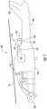
FIG. 1 is a side view of an exemplary aircraft including an exemplary exhaust system; -
FIG. 2 is a perspective view of a portion of the exhaust system shown inFIG. 1 illustrating an exhaust duct with an exemplary flow mixer and showing one implementation of a stiffener, or retainer, of the present disclosure; -
FIG. 3A is an enlarged view of a portion of the flow mixer shown inFIG. 2 ; -
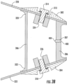
FIG. 3B is sectional view of one implementation of a flute tie and a retainer in accordance with the present disclosure; -
FIG. 4 is a schematic view of an alternate implementation of a first retainer and a second retainer each being attached to an opposing flute of an exhaust system; -
FIG. 5A is a perspective view of one implementation of a retainer of the present disclosure; -
FIG. 5B is a sectional view of the retainer shown inFIG. 5A ; -
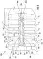
FIG. 6 is a perspective view of an alternative implementation showing a first retainer attached to an upper row of flutes and a second retainer attached to a lower row of flutes; -
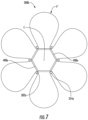
FIG. 7 is an end view of an alternate implementation illustrating an outlet of an exhaust system having radially disposed flutes and a plurality of retainers coupled to such flutes; -
FIG. 8A is a schematic view of an alternate implementation illustrating an outlet of an exhaust system having a first retainer coupled to two pairs of opposing flutes and a second retainer coupled to another pair of opposing flutes; -
FIG. 8B is a schematic view of an alternate implementation illustrating an outlet of an exhaust system having a first retainer coupled to two pairs of opposing flutes and a second retainer coupled to three medial, or central, pairs of flutes; -
FIG. 9 is a flow diagram of an exemplary aircraft production and service methodology; and -
FIG. 10 is a block diagram of an exemplary aircraft. - Examples of the present disclosure will now be described more fully hereinafter with reference to the accompanying drawings, in which some, but not all examples of the disclosure are shown. Indeed, various exemplary aspects of the disclosure may be embodied in many different forms and should not be construed as limited to the examples set forth herein. Rather, these examples are provided so that this disclosure will be thorough and complete and will fully convey the scope of the disclosure to those skilled in the art. Like reference numerals refer to like elements throughout.
- The systems and/or methods described herein may restrict or restrain movement of an exhaust system by, at least in part, stiffening the exhaust system or a portion thereof to increase the natural frequency of the exhaust system while facilitating efficient mixing of hot exhaust air and cooler ambient air. More specifically, the herein-described systems and methods may restrain and/or stiffen an exhaust duct. In one aspect, at least one retainer is coupled to at least two flutes of a fluted duct to prevent relative movement between the flutes, thus facilitating reduction in stresses in the flutes.
- Referring now to
FIG. 1 , anaircraft 100 is illustrated. In a particular implementation,aircraft 100 is a rotorcraft. In other suitable implementations, theaircraft 100 may be vehicle that travels through airspace, such as, but not limited to, airplanes, unmanned aerial vehicles (UAVs), gliders, helicopters, spacecraft, and reusable launch vehicles, and/or any other object that travels through airspace. Furthermore, although the embodiments described herein are described as related to an aircraft, it is contemplated that systems and methods described herein can be implemented on any ground vehicle or waterborne vessel. - In the exemplary implementation,
aircraft 100 is a rotorcraft including anose 102, abody 104, aboom 106, and atail 108. Arotorshaft 110 extends outward frombody 104 and is coupled to at least onerotor 112 that rotates aboutrotorshaft 110 to provideaircraft 100 with lift and thrust.Aircraft 100 also includes anexhaust system 114 that includes anengine 116, anexhaust duct 118, and aflow mixer 120.Engine 116 is generally located inbody 104 and is coupled torotorshaft 110 such thatengine 116 provides the power necessary to rotaterotorshaft 110. During operation,engine 116 generates hotexhaust gases 122 that are channeled throughexhaust duct 118 and discharged fromaircraft 100 throughflow mixer 120 to the relatively coolerambient air 124.Flow mixer 120 is configured to mix the flows ofexhaust gases 122 andambient air 124 to produce agas mixture 126 that reduces the effect of hotexhaust gases 122 impinging on downstream components ofaircraft 100, such asboom 106 andtail 108. Mixing ofexhaust gases 122 andambient air 124 also facilitates reducing the heat signature ofaircraft 100 to potentially concealaircraft 100 from detection and heat seeking weapons. -
FIG. 2 is a perspective view of a portion ofexhaust system 114 illustratingexhaust duct 118, which includes an inlet end, or portion, 202, and an outlet end, or portion, 204 with anexemplary flow mixer 200. Anintermediate portion 203 between theinlet portion 202 and theoutlet portion 204 is configured to channel the flow of exhaust between theinlet portion 202 and theoutlet portion 204.Flow mixer 200 is one implementation offlow mixer 120 that may be used withexhaust system 114. In the implementation shown inFIG. 2 , flowmixer 200 is fabricated from a ceramic matrix composite (CMC) material that is able to repeatedly withstand exposure to hotexhaust gases 122. In another suitable implementation,flow mixer 200 is fabricated from a metallic or metal alloy material. Generally,flow mixer 200 may be fabricated from any material that facilitates operation ofexhaust system 114 as described herein. -
Inlet end 202 ofexhaust duct 118 is coupled to an outlet end ofexhaust system 114. In the exemplary embodiment, outlet end 204 ofexhaust duct 118 transitions gradually from theinlet end 202 to a lobed or fluted shape that facilitates mixing flow of hotexhaust gases 122 fromexhaust duct 118 with cooler ambient air.Outlet end 204 includes a plurality of flutes, generally F, that are spaced circumferentially aboutoutlet end 204 to formflow mixer 200. More specifically, in the exemplary implementation, plurality of flutes F atoutlet end 204 includes a plurality of adjacentupper flutes 206 and a plurality of adjacentlower flutes 208 that are spaced from one another in two horizontal rows perpendicular to the plane ofoutlet end 204.Upper flutes 206 are spaced fromlower flutes 208 by a predetermined distance D1 such that agap 210 is defined betweenupper flutes 206 andlower flutes 208. In another suitable implementation,flow mixer 200 may be oriented at 90 degrees or some other angle from the orientation shown inFIG. 2 such thatoutlet end 204 includes two substantially vertically-oriented or otherwise oriented rows of flutes. Generally,flow mixer 200 may be oriented in any manner that facilitates operation of flow mixer as described herein. -
Outlet end 204 is formed by continuous aninner surface 212 and anouter surface 214, respectively, of a wall portion, generally 215.Wall portion 215 includeselongated portions 217 forms a plurality of vertically-oriented, alternating flute peaks and flute troughs. More specifically,upper flutes 206 each include anupper peak 216, andlower flutes 208 each include alower peak 218. Similarly,upper flutes 206 each include anupper trough 220, andlower flutes 208 each include alower trough 222.Wall portion 215 defines a plurality ofsidewalls 224 and a plurality ofsidewalls 226. Eachsidewall adjacent sidewalls adjacent sidewall 224 and/or 226. In another suitable implementation,sidewalls 224 and/or 226 may have any orientation and may not be parallel to anadjacent sidewall 224 and/or 226. -
Upper flutes 206 may be defined by plurality ofsidewalls 224. Eachupper peak 216 extends between a pair ofadjacent sidewalls 224, and, similarly, eachupper trough 220 extends between an adjacent pair ofsidewalls 224 such that oneupper peak 216 and an adjacentupper trough 220 share acommon sidewall 224. Similarly, with respect tolower flutes 208, eachlower peak 218 extends between a pair ofadjacent sidewalls 226, and, similarly, eachlower trough 222 extends between an adjacent pair ofsidewalls 226 such that onelower peak 218 and an adjacentlower trough 222 share acommon sidewall 226. -
Flow mixer 200 may be configured such that eachupper flute 206 is oriented in parallel with an opposinglower flute 208. That is, eachupper flute 206 of the plurality ofupper flutes 206 is generally aligned along on an axis Y, such as illustrated inFIG. 6 , namely, Y1, Y2, etc., and a correspondinglower flute 208 of the plurality oflower flutes 208 is aligned along the same axis Y1, Y2, etc.. More specifically, an apex 228 (shown inFIG. 3 ) of eachupper trough 220 is aligned with an apex 230 (shown inFIG. 3 ) of a correspondinglower trough 222 such that apexes 228 and 230 are spaced apart by predetermined distance D1 along a respective axis Y. Becauseupper troughs 220 are aligned with a correspondinglower trough 222, it follows that eachupper peak 216 is aligned with a correspondinglower peak 218 and thatupper sidewalls 224 are aligned withlower sidewalls 226. -
Upper peaks 216 andlower peaks 218 andupper troughs 220 andlower troughs 222 facilitate mixing coolambient air 124 with hotexhaust gases 122 to facilitate producing a steady and spatially uniform flow of gas mixture 126 (shown inFIG. 3 ). In operation, the flow ofambient air 124 is directed alongexhaust duct 118 and aroundpeaks troughs ambient air 124 is directed towards anaxis 232. Simultaneously, hotexhaust gases 122 is directed throughexhaust duct 118 and throughpeaks troughs exhaust gases 122 is directed towardsaxis 232.Peaks troughs ambient air 124 andgases 122 to facilitate mixing flows ofgases 122 andambient air 124 into the flow ofgas mixture 126 that is cooler than the flow of hotexhaust gases 122. -
FIG. 3A is an enlarged view of a portion 5 (shown inFIG. 2 ) offlow mixer 200 illustrating astiffener mechanism 300 and retainer, generally 400, coupled thereto.Retainer 400 is discussed in more detail below.Stiffener mechanism 300 is coupled between anupper flute 206 and a correspondinglower flute 208, and, more specifically, between anupper trough 220 and a correspondinglower trough 222. In such a configuration,stiffener mechanism 300 can restrict movement ofupper flutes 206 andlower flutes 208 with respect to each other. Couplingupper flutes 206 andlower flutes 208 together usingstiffener mechanism 300 facilitates raising the natural frequency offlow mixer 200 sufficiently to prevent or avoid deflections ofupper flutes 206 andlower flutes 208 resulting from resonance with a rotor frequency. Althoughstiffener mechanism 300 is described herein as extending between corresponding upper and lower sets ofupper flutes 206 andlower flutes 208 offlow mixer 200, it is contemplated thatstiffener mechanism 300 may be used on any fluted flow mixer and is not limited to use withonly flow mixer 200 as described herein. For example,stiffener mechanism 300 may extend between two or more flutes of a substantially radial flow mixer having circumferentially-spaced flutes. In such a configuration,stiffener mechanism 300 may extend between any number of flutes and is not restricted to extending between only two such flutes. -
Stiffener mechanism 300 preferably includes anupper cap 302, alower cap 304, and a flute tie, or body portion, 306 coupled betweenupper cap 302 andlower cap 304. Oneupper cap 302 is positioned within anupper trough 220 of each pair of opposingupper troughs 220 andlower troughs 222 such that anarcuate bottom surface 308 ofupper cap 302 is in contact with a substantially complementaryarcuate surface 234 ofupper trough 220. Similarly, onelower cap 304 is positioned within alower trough 222 of each pair of opposingupper trough 220 andlower troughs 222 such that anarcuate bottom surface 310 oflower cap 304 is in contact with a substantially complementaryarcuate surface 236 oflower trough 222. - Furthermore, each
upper cap 302 includes anopening 312 defined therethrough that is configured to receive anupper fastener 314 inserted therein. Similarly, eachlower cap 304 includes anopening 316 defined therethrough that is configured to receive alower fastener 318 inserted therein. Eachopening fastener respective cap upper caps 302 andlower caps 304 andupper fasteners 314 andlower fasteners 318 have a substantially thin profile within respectiveupper troughs 220 andlower troughs 222. The thin profile ofcaps caps flow mixer 200 and/or cause turbulence in the airflow. Each ofupper caps 302 andlower caps 304 can include at least one flow mixing feature, such as a flute F that facilitates efficient mixing of hotexhaust gases 122 withambient air 124. - In
FIG. 3B ,body portion 306 ofstiffener mechanism 300 may include anupper end 320 coupled toupper trough 220 and alower end 322 coupled tolower trough 222.Upper end 320 includes anupper opening 324 that is aligned with opening 312 inupper cap 302 such thatupper fastener 314 is inserted throughopening 312, throughupper trough 220, and intoopening 324. As such, at least a portion ofupper trough 220 is coupled betweenupper cap 302 andupper end 320 ofbody portion 306. Similarly,lower end 322 includes alower opening 326 that is aligned with opening 316 inlower cap 304 such thatlower fastener 318 is inserted throughopening 316, throughlower trough 222, and into thelower opening 326. As such, at least a portion oflower trough 222 is coupled betweenlower cap 304 andlower end 322 ofbody portion 306. In a configuration in which each offasteners respective sidewalls fasteners upper flutes 206 andlower flutes 208 are subjected to stresses that would cause deflections if not forstiffener mechanism 300. -
Body portion 306 may be configured to not unnecessarily impede the flow of enable hot exhaust gases 122 (shown inFig. 1 ) throughoutlet end 204. As such,body portion 306 facilitates maintaining the aerodynamic and performance features of flow mixer 200.,Body portion 306 can include any cross-sectional profile shape that enablesflow mixer 200 to operate as described herein. - In
FIGS. 3A and3B ,stiffener mechanism 300 is preferably fabricated from a metallic or metal alloy material that is able to repeatedly withstand exposure to hotexhaust gases 122. In another suitable implementation,stiffener mechanism 300 is fabricated from a CMC material. Generally,stiffener mechanism 300 may be fabricated from any material that facilitates operation ofexhaust system 114 as described herein. Furthermore,body portion 306 may be fabricated from a different material thanupper caps 302 andlower caps 304. Thebody portion 306 is preferably removable fromcaps flow mixer 200 to enable replacement thereof due to impact events or prolonged exposure. Additionally,body portion 306 may be substantially hollow with the exception of wherefasteners stiffener mechanism 300 and may be fabricated using a 3-dimensional printing process of any material described above. - Although
FIGs. 2 ,3A , and3B depict astiffener mechanism 300 between each pair or correspondingupper flutes 206 andlower flutes 208, it is contemplated thatflow mixer 200 may includefewer stiffener mechanisms 300, such as at only every other pair offlutes stiffener mechanism 300 at the ends of each plurality offlutes flow mixer 200 may include any number ofstiffener mechanisms 300 that enableexhaust system 114 to operate as described herein. - Turning to
FIGs. 2 ,3A and3B , theretainer 400 ofstiffener mechanism 300 will be discussed in more detail. InFIG. 2 ,retainer 400 is shown spanning between and interconnecting thebody portions 306 joining opposingupper troughs 220 andlower troughs 222 of flutes F, each of the flutes defining a height dimension H and a width dimension W generally perpendicular to the height dimension, wherein the height dimension is greater than the width dimension. The joining together of body portions, or flute ties, 306 adds further rigidity and stiffness to flowmixer 200, thereby facilitating the further raising the natural frequency offlow mixer 200. - Retainer, generally 400, could be a single member or could include two or more retainer segments (as shown in
FIGs. 7 and8A ), can be implemented in a variety of different configurations for stiffeningexhaust system 114, and only several of such configurations are shown herein. In the implementation shown inFIG. 2 ,retainer 400 extends generally perpendicular to one or more vertical axes, e.g., Y1-5 (shown inFIG. 6 ) that extend collinear to the respective height dimension H of each flute F. Such vertical axes are generally parallel to one another and, accordingly, are generally perpendicular with respect to and correspond to the width dimensions W that are measured in the direction of horizontal axes X, e.g., X1, X2, of each flute F of an upper row 207 and a lower row 209 of flutes F (shown inFIG. 6 ). Flutes F in upper row 207 are considered to beupper flutes 206, and flutes F in lower row 209 are considered to belower flutes 208.Retainer 400 is configured to generally restrain relative movement between adjacent flutes F and also between flutes F and remainder of theexhaust system 114, includinginlet portion 202 and theoutlet portion 204. -
Retainer 400 is preferably, an elongated strip having atop surface 401, abottom surface 402, and a rear surface, or trailing edge, 403, and could be constructed of a material such as INCONEL® 625, or any other suitable material. ("Inconel" is a registered trademark of Huntington Alloys Corporation of West Virginia, USA.)Retainer 400 can be coupled totroughs 220 and/or 222 of flutes F via one ormore flute ties 306 by welding, adhesive, mechanical fasteners (not shown), or other suitable means. The trailing surface offlute ties 306 may include a slot or notch 307 (FIG. 3B ) configured to receiveretainer 400. Thenotch 307 may include an angled or curved surface complimentary to the dog-eared, or faceted, cross-section of a generally aerodynamicleading edge 404 ofretainer 400 formed fromangled surfaces FIGs. 5A and 5B ), configured to reduce drag of the flow of exhaust over theretainer 400. Alternately,retainer 400 could be coupled totroughs 220 and/or 222 of flutes F by being formed integrally withflute ties 306 and/or integrally with flutes F and/or flowmixer 200, if desired. While the length, width, and thickness ofretainer 400 can be different depending on particular applications and configurations, in one non-limiting implementation,retainer 400 can be between approximately 43.2 cm (17 inches) and 45.7 cm (18 inches) (in length, between approximately 0.51 cm (0.2 inches) and 0.76 cm (0.3 inches) inwidth 410 and between approximately 0.25 +/- 0.02 cm (0.100 +/- 0.009 inches) and 0.51 +/- 0.02 cm (0.2 +/- 0.009 inches) inthickness 408. -
Retainer 400 could also be directly attached to thetroughs 220 and/or 222 of flutes F in in addition or instead of toflute ties 306, either directly tosuch troughs 220 and/or 222, such as by welding, bonding, adhesives, etc., or by mechanical fasteners, such as show inFIG. 4 . InFIG. 4 ,retainers caps 302 and/or 304, respectively bywelds 407, adhesive, or some other suitable attachment.Caps troughs troughs 220 and/or 222. Awasher 313 is interposed between anupper fastener 314 and opening 312 ofupper cap 302 and between alower fastener 318 and opening 316 oflower cap 304. Thebottom surface 308 ofupper cap 302 is curved to nest withinupper trough 220, and similarly, thebottom surface 310 oflower cap 304 is curved to be received by and nest withinlower trough 222. -
FIG. 6 illustrates a flow mixer 200a preferably including fiveupper troughs 220 coupled together directly withretainer 400c, and fivelower troughs 222 are coupled together withretainer 400d. The five upper troughs are axially opposed to the five lower troughs along axes Y1, Y2, Y3, Y4, and Y5, respectively.Retainers troughs 220 and/or 222, respectively, through use of adhesive, welds, integral formation withtroughs 220 and/or 222, and/or some other suitable fastening manner. In this implementation,flute ties 306 may be eliminated, and in such case, theupper flutes 220 will be generally fixed with respect to relative movement to one another, and likewise, thelower troughs 222 will be generally limited to relative movement with respect to one another; however, the upper row 207 of flutes F could experience at least relative lateral movement with respect to the lower row 209 of flutes F. Depending on the application, allowing for relative generally lateral movement between upper row 207 and lower row 209 of flutes F may be desirable. -
FIG. 7 illustrates aflow mixer 200b preferably including flutes F' extending generally radially from a center C. Retainers, or retainer segments, 400e directly attach to troughs between adjacent flutes F', viacaps 302a andfasteners 314a, to reduce relative movement between the flutes F' and thereby stiffenflow mixer 200b. Instead ofcaps 302a andfasteners 314a,retainers 400e could be coupled to the troughs through welding, adhesives, bonding, and/or integral formation with the flutes F' or in some other suitable manner. -
FIG. 8A illustrates aflow mixer 200c preferably including a row ofupper flutes 206a and a row oflower flutes 208a, with opposed pairs of upper and lower flutes F each being interconnected via mechanical fasteners, such asupper caps 302 andlower caps 304 to flute ties 306. However, it is to be understood that flute ties 306 could be coupled to the flutes through welding, adhesive, integral formation with the flutes F or in some other suitable manner. Afirst retainer 400f couples together two pairs of outboard flutes Fa on one side offlow mixer 200c. Asecond retainer 400g couples together two pairs of outboard flutes Fc on the other side offlow mixer 200. The center, or middle, pair of opposed flutes Fb is not laterally restrained by a retainer and is thus freer to experience relative movement with respect to either of the remaining pairs of flutes Fa, Fb. This selective application of retainers to specific pairs of flutes allows for the tailoring of stiffness and, accordingly, natural frequency characteristics for a given situation and/or environment offlow mixer 200c. -
FIG. 8B illustrates aflow mixer 200d preferably including a row ofupper flutes 206a and a row oflower flutes 208a, with opposed pairs of upper and lower flutes F each being interconnected via mechanical fasteners, such asupper caps 302 andlower caps 304 to flute ties 306. As noted above, it is to be understood that flute ties 306 could be coupled to the flutes through welding, adhesives, mechanical fasteners, integral formation with the flutes F or in some other suitable manner.Retainer 400h joins together three center, or middle, pair of flutes Fd, while each outboard pair of flutes Fe, Ff offlow mixer 200d is not laterally restrained byretainer 400h, and each outboard pair of flutes Fe, Ff is thus relatively free to experience relative movement with respect to each other and with respect to the three central pairs of flutes Fd, as well as the other outboard pair of flutes. This is another non-limiting selective application of retainers which may be used to tailor the stiffness and, accordingly, the natural frequency characteristics for a given situation and/or environment offlow mixer 200d. - Given the above, the resonant frequency of an exhaust system may be increased by selecting flutes F to be restrained and orienting the elongated retainer to extend generally perpendicular to the elongated axis of each of the selected flutes, and, while maintaining the elongated retainer generally perpendicular to the elongated axis of each of the flutes, coupling the retainer to the flutes directly and/or to
flute ties 306 attached to such selected flutes, such that theretainer 400 generally restrains movement between the selected flutes. - The examples described herein include systems and apparatuses that are able to raise the natural frequency of a flow mixer in order to avoid the resonant frequencies of cyclical vibrations, such as the operation of one or more rotors, propellers, etc. The examples described herein include flow mixers that include a plurality of flutes for mixing of a hot exhaust air stream and a relatively cooler ambient air stream. The flow mixers include a stiffener mechanism having ties that extend between the upper and lower flutes and one or more horizontally extending retainers that connect, or couple, two or more of the flute ties together and being configured to prevent deflections of the flutes due to vibrational stresses and resonant frequencies. In one implementation, the stiffener mechanism includes caps positioned within corresponding upper and lower flute troughs and a body portion that extends between the troughs and is coupled to each of the caps. In such a configuration, the stiffener mechanism is loaded primarily with tension/compression forces during operation. A laterally-extending retainer strip may be coupled to one or more flute ties to generally fix or restrain relative movement of the flute ties, and correspondingly, the flutes to which the flute ties are coupled, thereby providing a stiffening effect. The stiffener mechanism may be integrally formed between the upper and lower flutes and the adjacent fluted ties of the flow mixer. The stiffener mechanism may be coupled to corresponding sidewalls of the flutes such that the stiffener mechanism is loaded primarily with shear forces during operation.
- The disclosure described herein facilitates raising the natural frequency of the flow mixer and preventing deflection of the flow mixer flutes due to aligning resonant frequencies and rotor vibrations. Such stiffening enables the use of larger size mixers that may provide more efficient flow mixing and which may also lengthen the service lifetime of the flow mixer due to reduced material fatigue. As such, the costs associated with manufacturing and maintaining multiple flow mixers may be reduced. Additionally, the stiffening potentially creates a more constant flute area, which could facilitate more efficient flow mixing, and while maintaining the aerodynamic shape and properties of the flow mixer.
- Accordingly, a method is described herein of increasing the resonant frequency of
exhaust system 114, which has at least oneexhaust duct 118 with flutes F. As shown inFIG. 6 , each flute F includes atrough elongated portion 217 with a respective axis Y1, Y2, etc. and alateral portion 219 having width W extending generally perpendicular to the respective axis Y1, Y2, etc., such that the length of theelongated portion 217 is greater than the width W of suchlateral portion 219. The method includes selecting afirst flute 221 from the plurality of flutes F, the first flute having a first axis Y1, and also selecting asecond flute 223. Thesecond flute 223 has a second axis Y2 generally parallel to the first axis Y1. The method includes orienting aretainer 400c to extend generally perpendicular to the first and second axes Y1, Y2. The method also includes coupling afirst portion 225 of theretainer 400c to thetrough 220 of thefirst flute 221 and asecond portion 227 of theretainer 400c to thetrough 220 of thesecond flute 223 such that theretainer 400c generally restrains movement between thefirst flute 221 and thesecond flute 223. - Referring
FIG. 9 , the disclosure may be described in the context of an aircraft manufacturing andservice method 10 and via an aircraft 12 (shown inFIG. 10 ). Aircraft 100 (shown inFIG. 1 ) is an example ofaircraft 12. Duringmethod 10, specification and design data ofaircraft 12 may be used 14 during the manufacturing process and other materials associated with the airframe may be procured 16. During production, component andsubassembly manufacturing 18 andsystem integration 20 ofaircraft 12 occurs, prior toaircraft 12 entering its certification anddelivery process 22. Upon successful satisfaction and completion of airframe certification,aircraft 12 may be placed inservice 24. While in service by a customer,aircraft 12 is scheduled for periodic, routine, and scheduled maintenance andservice 26, including any modification, reconfiguration, and/or refurbishment, for example. The manufacturing andservice method 10 may be implemented via vehicles other than an aircraft. Theexhaust duct 118 and/orstiffener mechanism 300 described herein may be procured 16, assembled 18, integrated 20, and/or maintained/serviced 26. - Each portion and process associated with aircraft manufacturing and/or
service 10 may be performed or completed by a system integrator, a third party, and/or an operator (e.g., a customer). For the purposes of this description, a system integrator may include without limitation any number of aircraft manufacturers and major-system subcontractors; a third party may include without limitation any number of venders, subcontractors, and suppliers; and an operator may be an airline, leasing company, military entity, service organization, and so on. - As shown in
FIG. 10 ,aircraft 12 produced viamethod 10 may include anairframe 28 having a plurality ofsystems 30 and an interior 32. Examples of high-level systems 30 include one or more of apropulsion system 34, anelectrical system 36, ahydraulic system 38, and/or anenvironmental system 40. Any number of other systems may be included. Theexhaust duct 118 and/orstiffener mechanism 300 are preferably parts ofpropulsion system 34. - Apparatus and methods embodied herein may be employed during any one or more of the stages of
method 10. For example, components or subassemblies corresponding toproduction process 18 may be fabricated or manufactured in a manner similar to components or subassemblies produced whileaircraft 12 is in service. Also, one or more apparatus implementations, method implementations, or a combination thereof may be utilized during the production stages 18 and 20, for example, by substantially expediting assembly of, and/or reducing the cost of assembly ofaircraft 12. Similarly, one or more of apparatus implementations, method implementations, or a combination thereof may be utilized whileaircraft 12 is being serviced or maintained, for example, during scheduled maintenance andservice 26. - Further, the aircraft manufacturing and service method described herein may be used in any manufacturing, modification, repair and/or service operation.
- In summary, the disclosure described herein include a duct for directing a flow of exhaust, the duct including a wall portion defining a passageway having an inlet portion adapted to receive the flow of exhaust and an outlet portion adapted to discharge the flow of exhaust. A plurality of flutes is defined at the outlet portion, and the plurality of flutes include a first flute and a second flute spaced from the first flute. The first flute has a peak, a trough, a first height dimension and a first width dimension generally perpendicular to the first height dimension, and the second flute has a peak, a trough, a second height dimension and a second width dimension generally perpendicular to the second height dimension. At least one retainer is coupled to the trough of the first flute and the trough of the second flute and extends generally parallel to at least one of the first width dimension and the second width dimension, wherein the retainer is configured to restrain relative movement between the first flute and the second flute and relative movement among the first flute, the second flute, and at least one of the inlet portion and the outlet portion during the flow of exhaust through the duct.
- A first axis preferably corresponds to the first height dimension and a second axis preferably corresponds to the second height dimension, and the first axis and the second axis are preferably generally parallel to one another.
- The first flute can be adjacent the second flute, and in another aspect a fourth flute can be generally opposed to the second flute, and a second flute tie is coupled to the fourth flute and the second flute. The third flute may have s a third height dimension and a third axis can correspond to the third height dimension, the fourth flute may have a fourth height dimension and a fourth axis may correspond to the fourth height dimension, and the third axis and the fourth axis can be generally parallel to one another. The retainer may be coupled to the first flute tie and second flute tie.
- The retainer can be an elongated strip configured to extend at least between the first flute and the second flute, and in another aspect the retainer may include a generally aerodynamic angled leading edge configured to reduce drag of the flow of exhaust over the retainer.
- A third flute may generally be opposed to the first flute, and a first flute tie coupled to the third flute and the first flute, and in another aspect, a first axis corresponds to the first height dimension, the third flute has a third height dimension, and a third axis corresponds to the third height dimension, and wherein the first axis and the third axis are generally collinear with respect to one another.
- The retainer can be welded, bonded, adhered, formed integrally with the first flute tie and second flute tie and/or mechanically fastened to the first flute tie and the second flute tie. A first mechanical fastener may be coupled to the first flute, a second mechanical fastener coupled to the second flute, and the retainer coupled to at least one of the first mechanical fastener and the second mechanical fastener. The at least one retainer can include a first retainer and a second retainer, and the duct can further include a first mechanical fastener coupled to the first flute, a second mechanical fastener coupled to the second flute, the first retainer coupled to the first mechanical fastener, and the second retainer coupled to the second mechanical fastener.
- The outlet portion of the duct may have a centerline, a first axis corresponds to the first height dimension, and a second axis corresponds to the second height dimension, and the first axis and the second axis extend generally radially with respect to the centerline.
- In the duct, a third flute may generally be opposed to the first flute, and a first flute tie can be coupled to the third flute and the first flute. A fourth flute may be generally opposed to the second flute, and a second flute tie may be coupled to the fourth flute and the second flute. A fifth flute may be between the first flute and the second flute, and a sixth flute may generally be opposed to the fifth flute.
- The retainer can be coupled to the first flute tie and the second flute tie, and the third flute can be configured to have freedom of movement with respect to at least one of the retainer, the first flute, the second flute, the third flute, and the fourth flute. A third flute tie can be coupled to the fifth flute tie and the sixth flute tie and/or the retainer can be coupled to the first flute tie, the second flute tie, and the third flute tie.
- A third flute can be generally opposed to the first flute, and a first flute tie can be coupled to the third flute and the first flute. A fourth flute can be generally opposed to the second flute, and a second flute tie can be coupled to the fourth flute and the second flute. A fifth flute may be included, and a sixth flute may generally be opposed to the fifth flute. A seventh flute can be included, and an eighth flute may generally be opposed to the seventh flute. A third flute tie can be coupled to the fifth flute and the sixth flute, and a fourth flute tie can be coupled to the seventh flute and the eighth flute. Additional aspects include the at least one retainer having a first retainer and a second retainer and/or the first retainer coupled to at least the first flute tie and the second flute tie, and the second retainer coupled to at least the third flute tie and the fourth flute tie. In other aspects, at least one of the plurality of flutes is configured to have freedom of movement with respect to at least one other of the plurality of flutes and/or the retainer is coupled to the first flute tie, the second flute tie, the third flute tie, and the fourth flute tie.
- In the duct, the plurality of flutes can be arranged in opposing rows of flutes and/or the first height dimension is greater than the first width dimension and the second height dimension is greater than the second width dimension.
A stiffener apparatus for an exhaust duct can include a first row of flutes and a second row of flutes generally opposite to the first row of flutes, and each flute is elongated along a respective axis, and the stiffener apparatus includes at least two flute ties coupling together at least two flutes from the first row of flutes to at least two flutes from the second row of flutes. At least one retainer is coupled to the at least two flute ties and extends generally perpendicularly to the axis of each of the at least two flutes from the first row of flutes and the at least two flutes from the second row of flutes, wherein the retainer is configured to generally restrain relative movement between the at least two flutes from the first row of flutes and the at least two flutes from the second row of flutes. - A method is described for increasing the resonant frequency of an exhaust system having at least one duct, the duct including a plurality of flutes. Each flute includes a trough and an elongated portion with a respective axis and a lateral portion extending generally perpendicular to the respective axis, wherein the length of the elongated portion is greater than the width of the lateral portion. The method includes selecting a first flute from the plurality of flutes, the first flute having a first axis and selecting a second flute from the plurality of flutes, the second flute having a second axis generally parallel to the first axis. The retainer is oriented to extend generally perpendicular to the first and second axes, and a first portion of the retainer is coupled to the trough of the first flute and a second portion of the retainer is coupled to the trough of the second flute such that the retainer generally restrains movement between the first flute and the second flute.
- A method is also described for increasing the resonant frequency of an exhaust system having at least one duct, the duct including at least one row of flutes with a first side of the row having flutes oriented in a first direction and a second side of the row having flutes oriented in a second direction generally opposite to the first direction. Each flute defines an elongated portion extending along a respective axis and a lateral portion extending generally perpendicular to the respective axis, wherein the length of the elongated portion is greater than the width of the lateral portion. The method includes selecting a first flute and a second flute from the first side of the row of flutes and selecting a third flute and a fourth flute from the second side of the row of flutes. A first flute tie is coupled to the first flute and the third flute such that the first flute tie is generally parallel to the axis of each of the first flute and the third flute, and a second flute tie is coupled to the second flute and the fourth flute such that the second flute tie is generally parallel to the axis of each of the second flute and the fourth flute. A retainer is oriented generally perpendicular to a length of at least one of the first flute tie and the second flute tie. A first portion of the retainer is coupled to the first flute, and a second portion of the retainer is coupled to the second flute such that the retainer restrains movement between the first flute and the second flute, wherein the retainer restrains movement among the first flute, second flute, third flute, and fourth flute.
- Although specific features of various examples of the invention may be shown in some drawings and not in others, this is for convenience only. In accordance with the principles of the invention, any feature of a drawing may be referenced and/or claimed in combination with any feature of any other drawing.
- This written description uses examples to disclose various examples, which include the best mode, to enable any person skilled in the art to practice those examples, including making and using any devices or systems and performing any incorporated methods. The patentable scope is defined by the claims, and may include other examples that occur to those skilled in the art. Such other examples are intended to be within the scope of the claims if they have structural elements that do not differ from the literal language of the claims.
-
manufacturing and service method 10 aircraft 12 production process 18 component and subassembly manufacturing 18 during the production stages 18 assembled 18 production stages 18 and 20 integrated 20 system integration 20 certification and delivery process 22 in service 24 or maintained/serviced 26 scheduled maintenance and service 26 an airframe 28 high-level systems 30 an interior 32 a propulsion system 34 an electrical system 36 a hydraulic system 38 an environmental system 40 aircraft 100 a nose 102 a body 104 bOOM 106 tail 108 rotorshaft 110 rotor 112 an exhaust system 114 engine 116 exhaust duct 118 Flow mixer 120 hot exhaust gases 122 ambient air 124 gas mixture 126 flow mixer 200 inlet portion or inlet end 202 An intermediate portion 203 outlet portion or outlet end 204 an upper flute 206 first/upper row 207 lower flutes 208 second/lower row 209 a gap 210 inner surface 212 outer surface 214 Wall portion 215 Upper peak 216 elongated portions 217 Lower peak 218 lateral portion 219 upper trough 220 first flute 221 lower trough 222 second flute 223 upper sidewalls 224 a first portion 225 lower sidewalls 226 a second portion 227 an apex 228 an apex 230 axis 232 arcuate surface 234 arcuate surface 236 Stiffener mechanism 300 an upper cap 302 lower caps 304 flute ties or body portion 306 a slot or notch 307 an arcuate bottom surface 308 an arcuate bottom surface 310 upper opening 312 A washer 313 upper fastener 314 lower opening 316 lower fastener 318 upper end 320 lower end 322 an upper opening 324 a lower opening 326 Retainer 400 a top surface 401 a bottom surface 402 trailing edge 403 leading edge 404 welds 407
Claims (15)
- A duct (118) for directing a flow of exhaust gases (122), the duct comprising:- a flow mixer (200) having an inlet portion (202) adapted to receive the flow of exhaust gases and an outlet portion (204) adapted to discharge the flow of exhaust gases;- a plurality of flutes, defined at the outlet portion, the plurality of flutes including a first flute (206, 221) and a second flute (208, 223), spaced from the first flute, the first flute having a first peak (216), a first trough (220), a first height dimension, and a first width dimension, generally perpendicular to the first height dimension, the second flute having a second peak (218), a second trough (222), a second height dimension, and a second width dimension generally perpendicular to the second height dimension; and- at least two flute ties (306), wherein a first flute tie is coupled to the first trough (220) and wherein a second flute tie is coupled to the second trough (222); and- at least one retainer (400), directly attached to the first trough (220) and the second trough (222) of the flutes in addition to or instead of the at least two flute ties (306) and extending generally parallel to at least one of the first width dimension and the second width dimension;- wherein:- the at least one retainer is coupled to the flute tie; and- the at least one retainer is configured to restrain relative movement between the first flute and the second flute and relative movement among the first flute, the second flute, and at least one of the inlet portion and the outlet portion during the flow of exhaust gases through the duct.
- The duct of claim 1, further comprising:- a third flute, generally opposed to the first flute; and- a fourth flute, generally opposed to the second flute;- wherein:- the first flute tie is coupled to the third flute and the first flute;- the second flute tie is coupled to the fourth flute and the second flute; and
the at least one retainer is coupled to the first flute tie and the second flute tie. - The duct of claim 2, wherein:a first axis corresponds to the first height dimension, the third flute has a third height dimension, and a third axis corresponds to the third height dimension;the first axis and the third axis are generally collinear with respect to one another;the fourth flute has a fourth height dimension and a fourth axis corresponds to the fourth height dimension; andthe third axis and the fourth axis are generally parallel to one another.
- The duct of claim 2 or 3, wherein:- the first flute is adjacent the second flute;- the third flute is adjacent the fourth flute; and- the first flute tie is generally parallel to the second flute tie.
- The duct of claim 1, further comprising:- a third flute generally opposed to the first flute;- the first flute tie coupled to the third flute and the first flute;- a fourth flute generally opposed to the second flute;- the second flute tie coupled to the fourth flute and the second flute;- a fifth flute between the first flute and the second flute; and- a sixth flute generally opposed to the fifth flute.
- The duct of claim 5, wherein the retainer is coupled to the first flute tie and the second flute tie, and wherein the third flute is configured to have freedom of movement with respect to at least one of the at least one retainer, the first flute, the second flute, and the fourth flute.
- The duct of claim 5 or 6, wherein the at least one retainer is coupled to the first flute tie, the second flute tie, and a third flute tie.
- The duct of claim 1, further comprising:- a third flute generally opposed to the first flute,- wherein the first flute tie is coupled to the third flute and the first flute;- a fourth flute generally opposed to the second flute;- wherein the second flute tie is coupled to the fourth flute and the second flute;- a fifth flute;- a sixth flute generally opposed to the fifth flute;- a seventh flute; and- an eighth flute generally opposed to the seventh flute.
- The duct of claim 8, further comprising:- a third flute tie, coupled to the fifth flute and the sixth flute; and- a fourth flute tie, coupled to the seventh flute and the eighth flute.
- The duct of claim 9, wherein the at least one retainer is coupled to the first flute tie, the second flute tie, the third flute tie, and the fourth flute tie.
- The duct of claim 9 or 10, wherein the at least one retainer comprises a first retainer and a second retainer.
- The duct of claim 1 or 2, wherein:a first axis corresponds to the first height dimension, a second axis corresponds to the second height dimension, and the first axis and the second axis are generally parallel to one another; and/orthe outlet portion has a centerline, the first axis corresponds to the first height dimension, the second axis corresponding to the second height dimension, and the first axis and the second axis extend generally radially with respect to the centerline; and/orthe first height dimension is greater than the first width dimension, and the second height dimension is greater than the second width dimension.
- A method of increasing a resonant frequency of an exhaust system (114), having at least one duct (118) according to claim 1, the method comprising:- selecting the first flute (206, 221) from the plurality of flutes, the first flute (206, 221) having a first axis;- selecting the second flute (208, 223) from the plurality of flutes, the second flute (208, 223) having a second axis, generally parallel to the first axis;- orienting the at least one retainer (400) to extend generally perpendicular to the first axis and to the second axis; and- coupling a first portion of the at least one retainer (400) to the first trough (220) of the first flute (206, 221) and a second portion of the at least one retainer (400) to the second trough (222) of the second flute (208, 223) such that the at least one retainer (400) generally restrains movement between the first flute (206, 221) and the second flute (208, 223).
- An exhaust system, comprising a duct according to any of claims 1 to 12.
- An aircraft, comprising an exhaust system according to claim 14.
Priority Applications (1)
| Application Number | Priority Date | Filing Date | Title |
|---|---|---|---|
| EP20176145.9A EP3722584B1 (en) | 2016-08-02 | 2017-05-01 | Stiffener mechanism for an exhaust duct |
Applications Claiming Priority (1)
| Application Number | Priority Date | Filing Date | Title |
|---|---|---|---|
| US15/226,451 US10119449B2 (en) | 2016-08-02 | 2016-08-02 | Systems and methods for restraining exhaust gas ducts |
Related Child Applications (2)
| Application Number | Title | Priority Date | Filing Date |
|---|---|---|---|
| EP20176145.9A Division-Into EP3722584B1 (en) | 2016-08-02 | 2017-05-01 | Stiffener mechanism for an exhaust duct |
| EP20176145.9A Division EP3722584B1 (en) | 2016-08-02 | 2017-05-01 | Stiffener mechanism for an exhaust duct |
Publications (2)
| Publication Number | Publication Date |
|---|---|
| EP3279457A1 EP3279457A1 (en) | 2018-02-07 |
| EP3279457B1 true EP3279457B1 (en) | 2025-07-02 |
Family
ID=58664541
Family Applications (2)
| Application Number | Title | Priority Date | Filing Date |
|---|---|---|---|
| EP17168894.8A Active EP3279457B1 (en) | 2016-08-02 | 2017-05-01 | Systems and methods for restraining exhaust gas ducts |
| EP20176145.9A Active EP3722584B1 (en) | 2016-08-02 | 2017-05-01 | Stiffener mechanism for an exhaust duct |
Family Applications After (1)
| Application Number | Title | Priority Date | Filing Date |
|---|---|---|---|
| EP20176145.9A Active EP3722584B1 (en) | 2016-08-02 | 2017-05-01 | Stiffener mechanism for an exhaust duct |
Country Status (3)
| Country | Link |
|---|---|
| US (1) | US10119449B2 (en) |
| EP (2) | EP3279457B1 (en) |
| RU (1) | RU2737061C2 (en) |
Families Citing this family (5)
| Publication number | Priority date | Publication date | Assignee | Title |
|---|---|---|---|---|
| US12601283B2 (en) * | 2019-04-08 | 2026-04-14 | Pratt & Whitney Canada Corp. | Turbine exhaust case mixer |
| US11448160B2 (en) * | 2019-09-23 | 2022-09-20 | General Electric Company | High temperature gradient gas mixer |
| CN110654569B (en) * | 2019-09-29 | 2022-01-07 | 中国直升机设计研究所 | Load simulation simplification method for helicopter tail section fatigue test |
| CN112160804B (en) * | 2020-09-25 | 2023-03-24 | 中国直升机设计研究所 | Engine exhaust pipe fairing |
| US12529325B1 (en) | 2025-07-29 | 2026-01-20 | Pratt & Whitney Canada Corp. | Turbine exhaust duct with stiffeners for aircraft engines |
Family Cites Families (9)
| Publication number | Priority date | Publication date | Assignee | Title |
|---|---|---|---|---|
| GB1605457A (en) * | 1977-03-05 | 2008-07-16 | Rolls Royce | Improvements in or relating to reheat system for gas turbine engines |
| US4335801A (en) | 1980-12-15 | 1982-06-22 | The Boeing Company | Noise suppressing nozzle |
| US5265807A (en) | 1992-06-01 | 1993-11-30 | Rohr, Inc. | Aerodynamic stiffening ring for an aircraft turbine engine mixer |
| JPH112156A (en) | 1997-06-13 | 1999-01-06 | Ishikawajima Harima Heavy Ind Co Ltd | Lobe type two-dimensional mixer for jet engine |
| US6016651A (en) * | 1997-06-24 | 2000-01-25 | Sikorsky Aircraft Corporation | Multi-stage mixer/ejector for suppressing infrared radiation |
| FR2875854B1 (en) * | 2004-09-29 | 2009-04-24 | Snecma Propulsion Solide Sa | MIXER FOR TUYERE WITH SEPARATE FLUX |
| US7506501B2 (en) * | 2004-12-01 | 2009-03-24 | Honeywell International Inc. | Compact mixer with trimmable open centerbody |
| US20140260283A1 (en) | 2013-03-12 | 2014-09-18 | Pratt & Whitney Canada Corp. | Gas turbine engine exhaust mixer with aerodynamic struts |
| US9188024B2 (en) * | 2013-02-22 | 2015-11-17 | Pratt & Whitney Canada Corp. | Exhaust section for bypass gas turbine engines |
-
2016
- 2016-08-02 US US15/226,451 patent/US10119449B2/en active Active
-
2017
- 2017-04-18 RU RU2017113424A patent/RU2737061C2/en active
- 2017-05-01 EP EP17168894.8A patent/EP3279457B1/en active Active
- 2017-05-01 EP EP20176145.9A patent/EP3722584B1/en active Active
Also Published As
| Publication number | Publication date |
|---|---|
| EP3279457A1 (en) | 2018-02-07 |
| RU2737061C2 (en) | 2020-11-24 |
| US20180038261A1 (en) | 2018-02-08 |
| EP3722584B1 (en) | 2024-07-03 |
| RU2017113424A (en) | 2018-10-18 |
| US10119449B2 (en) | 2018-11-06 |
| EP3722584A1 (en) | 2020-10-14 |
| RU2017113424A3 (en) | 2020-05-28 |
Similar Documents
| Publication | Publication Date | Title |
|---|---|---|
| EP3279457B1 (en) | Systems and methods for restraining exhaust gas ducts | |
| US9168716B2 (en) | Metallic sandwich structure having small bend radius | |
| US7926285B2 (en) | Modular chevron exhaust nozzle | |
| US9567062B2 (en) | Box wing with angled gas turbine engine cores | |
| US12345174B1 (en) | Turbine engine airfoil | |
| US12492642B2 (en) | Outlet guide vane assembly for a turbofan engine | |
| EP4579650A1 (en) | Acoustic panel for an aircraft propulsion system | |
| US20100193605A1 (en) | Thermally balanced aero structures | |
| US20210221491A1 (en) | Fuselage shield for an aircraft with an unducted engine | |
| EP3628589B1 (en) | Active laminar flow control structural plenums fastened | |
| US20250214712A1 (en) | Acoustic panel for an aircraft propulsion system | |
| US8839629B2 (en) | Assembly for attaching the hangers from which an aircraft propulsion unit is suspended | |
| US20100192590A1 (en) | Thermally balanced materials | |
| US20240209748A1 (en) | Outlet guide vane assembly for a turbofan engine | |
| US11268390B2 (en) | Vortex generators for turbine engine exhaust | |
| US12103702B2 (en) | Removeable fuselage shield for an aircraft | |
| US7500353B2 (en) | Eductor swirl buster | |
| EP0145809B1 (en) | Apparatus and method for minimizing engine backbone bending | |
| US10480451B2 (en) | Systems and methods for restricting movement in flexible ducts | |
| EP3771645B1 (en) | Inlet bulkheads for large diameter aircraft engines | |
| EP2750972B1 (en) | Motion restrictor system for an aircraft engine | |
| EP4579651A1 (en) | Acoustic panel for an aircraft propulsion system | |
| US20250382880A1 (en) | Turbine engine airfoil | |
| US12571323B2 (en) | Turbine engine airfoil | |
| US12509988B2 (en) | Turbine engine airfoil |
Legal Events
| Date | Code | Title | Description |
|---|---|---|---|
| PUAI | Public reference made under article 153(3) epc to a published international application that has entered the european phase |
Free format text: ORIGINAL CODE: 0009012 |
|
| STAA | Information on the status of an ep patent application or granted ep patent |
Free format text: STATUS: REQUEST FOR EXAMINATION WAS MADE |
|
| 17P | Request for examination filed |
Effective date: 20170501 |
|
| AK | Designated contracting states |
Kind code of ref document: A1 Designated state(s): AL AT BE BG CH CY CZ DE DK EE ES FI FR GB GR HR HU IE IS IT LI LT LU LV MC MK MT NL NO PL PT RO RS SE SI SK SM TR |
|
| AX | Request for extension of the european patent |
Extension state: BA ME |
|
| GRAP | Despatch of communication of intention to grant a patent |
Free format text: ORIGINAL CODE: EPIDOSNIGR1 |
|
| STAA | Information on the status of an ep patent application or granted ep patent |
Free format text: STATUS: GRANT OF PATENT IS INTENDED |
|
| RIC1 | Information provided on ipc code assigned before grant |
Ipc: F01N 13/08 20100101ALI20200115BHEP Ipc: F02K 1/48 20060101AFI20200115BHEP |
|
| INTG | Intention to grant announced |
Effective date: 20200218 |
|
| GRAJ | Information related to disapproval of communication of intention to grant by the applicant or resumption of examination proceedings by the epo deleted |
Free format text: ORIGINAL CODE: EPIDOSDIGR1 |
|
| STAA | Information on the status of an ep patent application or granted ep patent |
Free format text: STATUS: REQUEST FOR EXAMINATION WAS MADE |
|
| INTC | Intention to grant announced (deleted) | ||
| GRAJ | Information related to disapproval of communication of intention to grant by the applicant or resumption of examination proceedings by the epo deleted |
Free format text: ORIGINAL CODE: EPIDOSDIGR1 |
|
| STAA | Information on the status of an ep patent application or granted ep patent |
Free format text: STATUS: EXAMINATION IS IN PROGRESS |
|
| 17Q | First examination report despatched |
Effective date: 20200616 |
|
| INTC | Intention to grant announced (deleted) | ||
| RAP3 | Party data changed (applicant data changed or rights of an application transferred) |
Owner name: THE BOEING COMPANY |
|
| GRAP | Despatch of communication of intention to grant a patent |
Free format text: ORIGINAL CODE: EPIDOSNIGR1 |
|
| STAA | Information on the status of an ep patent application or granted ep patent |
Free format text: STATUS: GRANT OF PATENT IS INTENDED |
|
| INTG | Intention to grant announced |
Effective date: 20240201 |
|
| GRAJ | Information related to disapproval of communication of intention to grant by the applicant or resumption of examination proceedings by the epo deleted |
Free format text: ORIGINAL CODE: EPIDOSDIGR1 |
|
| STAA | Information on the status of an ep patent application or granted ep patent |
Free format text: STATUS: EXAMINATION IS IN PROGRESS |
|
| INTC | Intention to grant announced (deleted) | ||
| GRAP | Despatch of communication of intention to grant a patent |
Free format text: ORIGINAL CODE: EPIDOSNIGR1 |
|
| STAA | Information on the status of an ep patent application or granted ep patent |
Free format text: STATUS: GRANT OF PATENT IS INTENDED |
|
| INTG | Intention to grant announced |
Effective date: 20241202 |
|
| GRAS | Grant fee paid |
Free format text: ORIGINAL CODE: EPIDOSNIGR3 |
|
| GRAA | (expected) grant |
Free format text: ORIGINAL CODE: 0009210 |
|
| STAA | Information on the status of an ep patent application or granted ep patent |
Free format text: STATUS: THE PATENT HAS BEEN GRANTED |
|
| AK | Designated contracting states |
Kind code of ref document: B1 Designated state(s): AL AT BE BG CH CY CZ DE DK EE ES FI FR GB GR HR HU IE IS IT LI LT LU LV MC MK MT NL NO PL PT RO RS SE SI SK SM TR |
|
| REG | Reference to a national code |
Ref country code: GB Ref legal event code: FG4D |
|
| REG | Reference to a national code |
Ref country code: CH Ref legal event code: EP |
|
| REG | Reference to a national code |
Ref country code: DE Ref legal event code: R096 Ref document number: 602017090233 Country of ref document: DE |
|
| REG | Reference to a national code |
Ref country code: IE Ref legal event code: FG4D |
|
| P01 | Opt-out of the competence of the unified patent court (upc) registered |
Free format text: CASE NUMBER: APP_31440/2025 Effective date: 20250630 |
|
| REG | Reference to a national code |
Ref country code: NL Ref legal event code: MP Effective date: 20250702 |
|
| PG25 | Lapsed in a contracting state [announced via postgrant information from national office to epo] |
Ref country code: PT Free format text: LAPSE BECAUSE OF FAILURE TO SUBMIT A TRANSLATION OF THE DESCRIPTION OR TO PAY THE FEE WITHIN THE PRESCRIBED TIME-LIMIT Effective date: 20251103 |
|
| PG25 | Lapsed in a contracting state [announced via postgrant information from national office to epo] |
Ref country code: NL Free format text: LAPSE BECAUSE OF FAILURE TO SUBMIT A TRANSLATION OF THE DESCRIPTION OR TO PAY THE FEE WITHIN THE PRESCRIBED TIME-LIMIT Effective date: 20250702 |
|
| REG | Reference to a national code |
Ref country code: AT Ref legal event code: MK05 Ref document number: 1809471 Country of ref document: AT Kind code of ref document: T Effective date: 20250702 |
|
| PG25 | Lapsed in a contracting state [announced via postgrant information from national office to epo] |
Ref country code: IS Free format text: LAPSE BECAUSE OF FAILURE TO SUBMIT A TRANSLATION OF THE DESCRIPTION OR TO PAY THE FEE WITHIN THE PRESCRIBED TIME-LIMIT Effective date: 20251102 |
|
| PG25 | Lapsed in a contracting state [announced via postgrant information from national office to epo] |
Ref country code: NO Free format text: LAPSE BECAUSE OF FAILURE TO SUBMIT A TRANSLATION OF THE DESCRIPTION OR TO PAY THE FEE WITHIN THE PRESCRIBED TIME-LIMIT Effective date: 20251002 |
|
| REG | Reference to a national code |
Ref country code: LT Ref legal event code: MG9D |
|
| PG25 | Lapsed in a contracting state [announced via postgrant information from national office to epo] |
Ref country code: AT Free format text: LAPSE BECAUSE OF FAILURE TO SUBMIT A TRANSLATION OF THE DESCRIPTION OR TO PAY THE FEE WITHIN THE PRESCRIBED TIME-LIMIT Effective date: 20250702 |
|
| PG25 | Lapsed in a contracting state [announced via postgrant information from national office to epo] |
Ref country code: FI Free format text: LAPSE BECAUSE OF FAILURE TO SUBMIT A TRANSLATION OF THE DESCRIPTION OR TO PAY THE FEE WITHIN THE PRESCRIBED TIME-LIMIT Effective date: 20250702 |
|
| PG25 | Lapsed in a contracting state [announced via postgrant information from national office to epo] |
Ref country code: HR Free format text: LAPSE BECAUSE OF FAILURE TO SUBMIT A TRANSLATION OF THE DESCRIPTION OR TO PAY THE FEE WITHIN THE PRESCRIBED TIME-LIMIT Effective date: 20250702 |
|
| PG25 | Lapsed in a contracting state [announced via postgrant information from national office to epo] |
Ref country code: GR Free format text: LAPSE BECAUSE OF FAILURE TO SUBMIT A TRANSLATION OF THE DESCRIPTION OR TO PAY THE FEE WITHIN THE PRESCRIBED TIME-LIMIT Effective date: 20251003 |
|
| PG25 | Lapsed in a contracting state [announced via postgrant information from national office to epo] |
Ref country code: SE Free format text: LAPSE BECAUSE OF FAILURE TO SUBMIT A TRANSLATION OF THE DESCRIPTION OR TO PAY THE FEE WITHIN THE PRESCRIBED TIME-LIMIT Effective date: 20250702 Ref country code: CZ Free format text: LAPSE BECAUSE OF FAILURE TO SUBMIT A TRANSLATION OF THE DESCRIPTION OR TO PAY THE FEE WITHIN THE PRESCRIBED TIME-LIMIT Effective date: 20250702 |
|
| PG25 | Lapsed in a contracting state [announced via postgrant information from national office to epo] |
Ref country code: LV Free format text: LAPSE BECAUSE OF FAILURE TO SUBMIT A TRANSLATION OF THE DESCRIPTION OR TO PAY THE FEE WITHIN THE PRESCRIBED TIME-LIMIT Effective date: 20250702 |
|
| PG25 | Lapsed in a contracting state [announced via postgrant information from national office to epo] |
Ref country code: BG Free format text: LAPSE BECAUSE OF FAILURE TO SUBMIT A TRANSLATION OF THE DESCRIPTION OR TO PAY THE FEE WITHIN THE PRESCRIBED TIME-LIMIT Effective date: 20250702 Ref country code: PL Free format text: LAPSE BECAUSE OF FAILURE TO SUBMIT A TRANSLATION OF THE DESCRIPTION OR TO PAY THE FEE WITHIN THE PRESCRIBED TIME-LIMIT Effective date: 20250702 |
|
| PG25 | Lapsed in a contracting state [announced via postgrant information from national office to epo] |
Ref country code: RS Free format text: LAPSE BECAUSE OF FAILURE TO SUBMIT A TRANSLATION OF THE DESCRIPTION OR TO PAY THE FEE WITHIN THE PRESCRIBED TIME-LIMIT Effective date: 20251002 |
|
| PG25 | Lapsed in a contracting state [announced via postgrant information from national office to epo] |
Ref country code: ES Free format text: LAPSE BECAUSE OF FAILURE TO SUBMIT A TRANSLATION OF THE DESCRIPTION OR TO PAY THE FEE WITHIN THE PRESCRIBED TIME-LIMIT Effective date: 20250702 |
|
| PG25 | Lapsed in a contracting state [announced via postgrant information from national office to epo] |
Ref country code: SM Free format text: LAPSE BECAUSE OF FAILURE TO SUBMIT A TRANSLATION OF THE DESCRIPTION OR TO PAY THE FEE WITHIN THE PRESCRIBED TIME-LIMIT Effective date: 20250702 |
|
| PG25 | Lapsed in a contracting state [announced via postgrant information from national office to epo] |
Ref country code: DK Free format text: LAPSE BECAUSE OF FAILURE TO SUBMIT A TRANSLATION OF THE DESCRIPTION OR TO PAY THE FEE WITHIN THE PRESCRIBED TIME-LIMIT Effective date: 20250702 |
|
| PG25 | Lapsed in a contracting state [announced via postgrant information from national office to epo] |
Ref country code: IT Free format text: LAPSE BECAUSE OF FAILURE TO SUBMIT A TRANSLATION OF THE DESCRIPTION OR TO PAY THE FEE WITHIN THE PRESCRIBED TIME-LIMIT Effective date: 20250702 |