EP2750972B1 - Motion restrictor system for an aircraft engine - Google Patents
Motion restrictor system for an aircraft engine Download PDFInfo
- Publication number
- EP2750972B1 EP2750972B1 EP11757492.1A EP11757492A EP2750972B1 EP 2750972 B1 EP2750972 B1 EP 2750972B1 EP 11757492 A EP11757492 A EP 11757492A EP 2750972 B1 EP2750972 B1 EP 2750972B1
- Authority
- EP
- European Patent Office
- Prior art keywords
- inlet
- wall
- longitudinal members
- motion
- aircraft
- Prior art date
- Legal status (The legal status is an assumption and is not a legal conclusion. Google has not performed a legal analysis and makes no representation as to the accuracy of the status listed.)
- Active
Links
- 238000000034 method Methods 0.000 claims description 24
- 239000000463 material Substances 0.000 claims description 7
- 229910000831 Steel Inorganic materials 0.000 claims description 2
- RTAQQCXQSZGOHL-UHFFFAOYSA-N Titanium Chemical compound [Ti] RTAQQCXQSZGOHL-UHFFFAOYSA-N 0.000 claims description 2
- 229910052782 aluminium Inorganic materials 0.000 claims description 2
- XAGFODPZIPBFFR-UHFFFAOYSA-N aluminium Chemical compound [Al] XAGFODPZIPBFFR-UHFFFAOYSA-N 0.000 claims description 2
- 239000002131 composite material Substances 0.000 claims description 2
- 239000010959 steel Substances 0.000 claims description 2
- 239000010936 titanium Substances 0.000 claims description 2
- 229910052719 titanium Inorganic materials 0.000 claims description 2
- 238000004519 manufacturing process Methods 0.000 description 14
- 238000012423 maintenance Methods 0.000 description 9
- 230000008569 process Effects 0.000 description 7
- 230000007246 mechanism Effects 0.000 description 3
- 230000004048 modification Effects 0.000 description 3
- 238000012986 modification Methods 0.000 description 3
- 239000003381 stabilizer Substances 0.000 description 3
- 238000013461 design Methods 0.000 description 2
- 238000010586 diagram Methods 0.000 description 2
- 230000010354 integration Effects 0.000 description 2
- 230000009467 reduction Effects 0.000 description 2
- 238000009419 refurbishment Methods 0.000 description 2
- 241000219470 Mirabilis Species 0.000 description 1
- 240000005860 Portulaca grandiflora Species 0.000 description 1
- 230000008859 change Effects 0.000 description 1
- 230000005465 channeling Effects 0.000 description 1
- 238000010276 construction Methods 0.000 description 1
- 238000011161 development Methods 0.000 description 1
- 230000007613 environmental effect Effects 0.000 description 1
- 229910001092 metal group alloy Inorganic materials 0.000 description 1
- 230000008520 organization Effects 0.000 description 1
- 238000013519 translation Methods 0.000 description 1
Images


Classifications
-
- B64D27/40—
-
- B—PERFORMING OPERATIONS; TRANSPORTING
- B64—AIRCRAFT; AVIATION; COSMONAUTICS
- B64D—EQUIPMENT FOR FITTING IN OR TO AIRCRAFT; FLIGHT SUITS; PARACHUTES; ARRANGEMENTS OR MOUNTING OF POWER PLANTS OR PROPULSION TRANSMISSIONS IN AIRCRAFT
- B64D27/00—Arrangement or mounting of power plant in aircraft; Aircraft characterised thereby
-
- B64D27/404—
-
- B—PERFORMING OPERATIONS; TRANSPORTING
- B64—AIRCRAFT; AVIATION; COSMONAUTICS
- B64D—EQUIPMENT FOR FITTING IN OR TO AIRCRAFT; FLIGHT SUITS; PARACHUTES; ARRANGEMENTS OR MOUNTING OF POWER PLANTS OR PROPULSION TRANSMISSIONS IN AIRCRAFT
- B64D33/00—Arrangements in aircraft of power plant parts or auxiliaries not otherwise provided for
- B64D33/02—Arrangements in aircraft of power plant parts or auxiliaries not otherwise provided for of combustion air intakes
- B64D2033/0266—Arrangements in aircraft of power plant parts or auxiliaries not otherwise provided for of combustion air intakes specially adapted for particular type of power plants
- B64D2033/0273—Arrangements in aircraft of power plant parts or auxiliaries not otherwise provided for of combustion air intakes specially adapted for particular type of power plants for jet engines
-
- Y—GENERAL TAGGING OF NEW TECHNOLOGICAL DEVELOPMENTS; GENERAL TAGGING OF CROSS-SECTIONAL TECHNOLOGIES SPANNING OVER SEVERAL SECTIONS OF THE IPC; TECHNICAL SUBJECTS COVERED BY FORMER USPC CROSS-REFERENCE ART COLLECTIONS [XRACs] AND DIGESTS
- Y02—TECHNOLOGIES OR APPLICATIONS FOR MITIGATION OR ADAPTATION AGAINST CLIMATE CHANGE
- Y02T—CLIMATE CHANGE MITIGATION TECHNOLOGIES RELATED TO TRANSPORTATION
- Y02T50/00—Aeronautics or air transport
- Y02T50/40—Weight reduction
Definitions
- the present disclosure relates generally to aircraft and, in particular, to aircraft engines. Still more particularly, the present disclosure relates to a method and apparatus for reducing vibrations in an inlet of an aircraft engine.
- Aircraft engine is a component of a propulsion system for an aircraft that generates mechanical power to move the aircraft.
- Aircraft engines may take many different forms, depending on the type of aircraft in which they are used. For example, aircraft may use engines in the form of a turboprop, a turbojet, a turbofan, and other suitable types of engines.
- a turbofan is a type of jet engine that provides thrust using a combination of a ducted fan and a jet exhaust nozzle. These types of engines have rotating shafts or spools.
- Vibrations from these and other components may be undesirable with respect to the ride and comfort of passengers or may affect the durability of engine parts. For example, vibrations may also limit the speed at which the components may rotate. Further, when vibrations occur, maintenance for these types of engines may be needed more often than desired.
- FR 2942457 discloses a jet engine nacelle comprising an air intake structure for channeling a flow of air to a turbojet fan, a central structure attached to the air inlet structure and intended to surround the fan of the turbojet engine, the air intake structure comprising an inner panel secured to the central structure and a fixed structure forming therewith, and an outer panel including a lip air input at its end opposite to the middle structure, the outer panel being movable in longitudinal translation relative to the inner panel.
- an apparatus as defined in claim 1.
- a method for reducing vibrations in an inlet of an aircraft engine as defined in claim 13.
- an apparatus comprises a first wall and a plurality of longitudinal members.
- the first wall is for an inlet of an aircraft engine.
- the plurality of longitudinal members connects the first wall to a structure for the aircraft engine.
- the plurality of longitudinal members has an orientation configured to reduce motion in the inlet, wherein the motion reduced in the inlet is in an axial direction of the aircraft engine.
- a motion restrictor system for an inlet of an aircraft engine comprises a structure, an inlet, and a plurality of longitudinal members.
- the structure is in the aircraft engine.
- the inlet is connected to the aircraft engine.
- the plurality of longitudinal members has first ends connected to a wall of the inlet and second ends connected to the structure. Motion in an axial direction in the wall of the inlet caused by the structure is reduced.
- a method for reducing vibrations in an inlet of an aircraft engine is provided.
- the aircraft engine is operated such that vibrations are generated.
- the vibrations in the inlet are reduced with a plurality of longitudinal members connecting a first wall of the inlet to a second wall of a structure for the aircraft engine.
- the plurality of longitudinal members has an orientation configured to reduce the vibration in the inlet, wherein the motion reduced in the inlet is in an axial direction of the aircraft engine.
- the different advantageous embodiments recognize and take into account one or more different considerations.
- the different advantageous embodiments recognize and take into account that the rotating shaft and spools may contribute to the vibrations. These vibrations may extend into the housing and through other components in the engine.
- the different advantageous embodiments recognize and take into account that different mechanisms are currently used to reduce vibrations in a radial direction.
- mechanisms are currently available for reducing vibrations in a direction substantially perpendicular to an axis extending through the rotating shaft in the engine.
- the different advantageous embodiments also recognize and take into account that other types of vibrations may be present that may be undesirable.
- the different advantageous embodiments recognize and take into account that the different portions of an inlet attached to the housing of an engine may move back and forth in an axial direction. This motion may be caused by vibrations in other parts of the engine, such as the fan and spools. This axial direction is in the same direction as an axis extending through a shaft of the engine.
- this type of vibration in the axial direction may cause inconsistencies to occur in the inlet more quickly than desired.
- the inlet may need maintenance, rework, or replacement more often than desired.
- the different advantageous embodiments recognize and take into account that reducing vibrations for the inlet in an axial direction may be desirable.
- an apparatus comprises a first wall for an inlet of an aircraft engine.
- the apparatus also comprises a plurality of longitudinal members.
- the plurality of longitudinal members connects the first wall to a second wall of the structure for the aircraft engine.
- the plurality of longitudinal members has an orientation configured to reduce motion, such as vibrations, in the first wall.
- motion restrictor environment 100 includes aircraft 102.
- Aircraft 102 includes number of aircraft engines 104.
- a number when used with reference to an item, means one or more items.
- a number of engines may be one or more engines.
- motion restrictor system 106 may be implemented in aircraft engine 108 in any of number of aircraft engines 104. Motion restrictor system 106 may be installed or added to aircraft engine 108 at different times. For example, motion restrictor system 106 may be included in aircraft engine 108 during construction of aircraft engine 108. In another illustrative example, motion restrictor system 106 may be added to aircraft engine 108 during maintenance, refurbishment, or other operations with respect to aircraft engine 108.
- motion restrictor system 106 may be used to reduce motion 112 in inlet 110 of aircraft engine 108.
- Inlet 110 is attached to structure 114.
- Motion 116 generated by structure 114 during operation of aircraft engine 108 may cause motion 112 in inlet 110.
- motion 112 and motion 116 take the form of vibrations.
- Structure 114 may be any structure to which inlet 110 is connected.
- structure 114 may be fan case 118 for aircraft engine 108.
- motion 112 may cause inlet 110 to form inconsistencies or require replacement more often than desired.
- Motion restrictor system 106 comprises plurality of longitudinal members 120.
- Plurality of longitudinal members 120 connects first wall 122 in inlet 110 to second wall 124 in structure 114.
- a longitudinal member in plurality of longitudinal members 120 is a structure that is configured to extend from one component to another component, such as first wall 122 to second wall 124, and connect the components to each other.
- a first component "connected to" a second component means that the first component can be connected directly or indirectly to the second component.
- the first component may be first wall 122, and the second component may be second wall 124.
- additional components may be present between the first component and the second component.
- plurality of longitudinal members 120 are examples of additional components that connect the first component, first wall 122, to the second component, second wall 124.
- the first component is considered to be indirectly connected to the second component when one or more additional components are present between the two components. When the first component is directly connected to the second component, no additional components are present between the two components.
- plurality of longitudinal members 120 may be indirectly connected to second wall 124.
- plurality of connectors 126 may connect plurality of longitudinal members 120 to second wall 124.
- plurality of longitudinal members 120 may be connected to another structure in inlet 110 that may be connected to second wall 124.
- These structures may take the form of bulkheads in some illustrative examples.
- plurality of longitudinal members 120 has shape 128 and orientation 130. At least one of shape 128 and orientation 130 is configured to reduce motion 112 of inlet 110. Motion 112 may be used when plurality of longitudinal members 120 are connected to first wall 122 and second wall 124. In particular, motion 112 may be reduced for first wall 122 in inlet 110.
- the phrase "at least one of”, when used with a list of items, means different combinations of one or more of the listed items may be used and only one of each item in the list may be needed.
- “at least one of item A, item B, and item C” may include, for example, without limitation, item A or item A and item B. This example also may include item A, item B, and item C, or item B and item C.
- shape 128 for plurality of longitudinal members 120 may take a number of different forms.
- any longitudinal member may have any geometric shape, such as an I-beam, a beam, a T-section, a web, a C-channel, a rod, a cylinder, a closed structure, an open section, a closed section, and/or other suitable shapes.
- Orientation 130 is an axial direction 132.
- Axial direction 132 is in the same direction as axis 134 extending centrally through aircraft engine 108 in these illustrative examples.
- plurality of longitudinal members 120 is comprised of material 136.
- Material 136 also may be selected as one that may aid in reducing motion 112 for first wall 122. Further, material 136 may be selected as one that may withstand operational vibration of aircraft engine 108 for a desired period of time without causing any of plurality of longitudinal members 120 to change shape 128 in an undesired manner.
- Material 136 may be, for example, at least one of aluminum, a composite material, titanium, steel, a metal alloy, and other suitable types of material.
- plurality of connectors 126 are connected to first wall 122 and second wall 124 in configuration 138.
- plurality of connectors 126 is spaced apart from each other by substantially an equal amount of spacing.
- two longitudinal members may be spaced apart at a distance that is substantially equal to the spacing between two other longitudinal members in the plurality of longitudinal members.
- the spacing may be around the circumference of the inlet.
- configuration 138 may be a spacing of about 90 degrees around inlet 110.
- motion restrictor environment 100 in Figure 1 is not meant to imply physical or architectural limitations to a manner in which an advantageous embodiment may be implemented.
- Other components in addition to and/or in place of the ones illustrated may be used. Some components may be unnecessary.
- the blocks are presented to illustrate some functional components. One or more of these blocks may be combined and/or divided into different blocks when implemented in an advantageous embodiment.
- plurality of longitudinal members 120 may comprise two longitudinal members, three longitudinal members, five longitudinal members, eight longitudinal members, or some other suitable number of longitudinal members.
- configuration 138 may not include having substantially the same distance between longitudinal members in plurality of longitudinal members 120, depending on the design of inlet 110. In some cases, features or structures in inlet 110 may result in a different spacing for some longitudinal members within plurality of longitudinal members 120.
- motion restrictor system 106 may reduce motion 112.
- the reduction of motion 112 may reduce a development of inconsistencies in inlet 110.
- maintenance in inlet 110 may be reduced with the use of motion restrictor system 106 with inlet 110.
- FIGS. 2-15 illustrations of physical implementations for components, such as an aircraft, an engine, an inlet, and components for a motion restrictor system are depicted in accordance with an advantageous embodiment.
- components such as an aircraft, an engine, an inlet, and components for a motion restrictor system are depicted in accordance with an advantageous embodiment.
- the different components shown in these figures may be combined with the components in Figure 2 , using components in Figure 2 , or a combination of the two.
- some of the components shown in these figures may be illustrative examples of how components in block form in Figure 1 may be implemented as physical structures.
- Aircraft 200 is an example of a physical implementation for aircraft 102 illustrated in block form in Figure 1 .
- aircraft 200 has wing 202 and wing 204 attached to fuselage 206.
- Aircraft 200 also has horizontal stabilizer 208, horizontal stabilizer 210 and vertical stabilizer 212.
- Engine 214 is attached to wing 204, and engine 216 is attached to wing 202.
- Engine 214 and engine 216 are examples of physical implementations for number of aircraft engines 104 illustrated in block form in Figure 1 .
- one or more advantageous embodiments may be implemented in engine 214 and engine 216.
- motion restrictor system 106 in Figure 1 may be implemented for use with at least one of inlet 218 for engine 214 and inlet 220 for engine 216.
- FIG. 3 a more-detailed illustration of an engine is depicted in accordance with an advantageous embodiment.
- a partially-exposed view of engine 214 is illustrated.
- Fan case 300 is an example of a physical implementation for fan case 118 illustrated in block form in Figure 1 .
- undesired motion may occur in axial direction 302 with respect to inlet 218.
- Axial direction 302 is a direction corresponding to the direction of axis 304.
- inlet 218 may be connected to fan case 300 at locations, such as location 306.
- Motion in fan case 300 may be in axial direction 302, which causes movement of components in inlet 218 in axial direction 302.
- FIG. 4 Another illustration of an engine is depicted in accordance with an advantageous embodiment.
- engine 214 is shown in an exploded view.
- FIG. 5 an illustration of a view of an inlet is depicted in accordance with an advantageous embodiment.
- wall 500 of inlet 218 is seen in this perspective view.
- Wall 500 may be attached to fan case 300 in Figure 3 .
- a motion restrictor system may be implemented for use with inlet 218 to reduce motion in inlet 218.
- motion may be reduced for wall 502.
- the motion restrictor system may be implemented inside of inlet 218 under cover 504.
- Cover 504 may take the form of an outer cowl for inlet 218.
- motion restrictor system 600 is shown connected to inlet 218.
- motion restrictor system 600 comprises longitudinal member 602, longitudinal member 604, longitudinal member 606, and longitudinal member 608 in these illustrative examples. These longitudinal members are spaced apart from each other with substantially the same space.
- the longitudinal members may be spaced apart from each other about 90 degrees with respect to axis 304 extending centrally through inlet 218.
- Longitudinal members 602, 604, 606, and 608 are oriented in a manner that may reduce motion of wall 502 in axial direction 302.
- longitudinal members 602, 604, 606, and 608 are not aligned in axial direction 302. Instead, these longitudinal members are oriented such that they extend in a direction that has an angle with respect to axis 304. The angle for the longitudinal members is selected to reduce motion of inlet 218 in axial direction 302.
- the motion takes the form of vibrations that may travel through a structure, such as fan case 300, to inlet 218 during the operation of engine 214.
- longitudinal members 602, 604, 606, and 608 take the form of I-beams.
- these longitudinal members have a cross-sectional shape in the shape of an I-beam.
- the longitudinal members are angled in orientation in inlet 218 with respect to axis 304. More specifically, end 610 of longitudinal member 602 is shown as being connected closer to outer edge 612 as compared to inner edge 614 of wall 502. This location may be selected based on where the most motion is expected in wall 502. The selection of the location is made to reduce motion in wall 502 as much as possible.
- End 616 of longitudinal member 602 is located closer to inner edge 618 of wall 500 as compared to outer edge 620 of wall 500. This location is selected such that end 616 may be connected to another structure in engine 214.
- the structure is selected as one that is the source of the motion that occurs in inlet 218.
- This structure may be, for example, fan case 300 in Figure 3 .
- end 610 of longitudinal member 602 is connected to wall 502 of inlet 218.
- end 610 of longitudinal member 602 is connected indirectly to wall 502 through flange 702 extending from wall 502 of inlet 218.
- end 610 of longitudinal member 602 may be connected to flange 702 in a number of different ways.
- end 610 may be connected to flange 702 by one of a weld, a fastener, and/or other suitable mechanisms.
- a fastening or connector system also may be used to connect end 610 to flange 702.
- end 610 may be connected directly to wall 502.
- end 800 may be connected to a structure (not shown) in the engine, such as an engine case.
- connection to the structure may be made indirectly through wall 500 of inlet 218. Further, the connection may be made using connector system 802. Connector system 802 is connected to end 616 of longitudinal member 602. In turn, connector system 802 touches surface 804 of wall 500.
- Fasteners may be used to connect connector system 802 to both wall 500 and to fan case 300 in Figure 3 . In this manner, end 616 of longitudinal member 602 may be connected to fan case 300. This connection is an indirect connection through wall 500 in the illustrative example. In this example, a fastener may be placed though opening 806 in connector system 802.
- opening 900 also may be seen in addition to opening 806 in connector system 802. Opening 806 and opening 900 may receive fasteners that connect connector system 802 to fan case 300 in Figure 3 in these illustrative examples.
- the connection may be to a wall (not shown) of fan case 300.
- longitudinal member 602 is I-beam 1000.
- I-beam 1000 comprises substantially planar structure 1002 with flange 1004 and flange 1006 on side 1008 and side 1010, respectively, of substantially planar structure 1002.
- I-beam 1000 also may include flange 1012, flange 1014, and flange 1016, which extends substantially perpendicular from surface 1018 of substantially planar structure 1002.
- flange 1100, flange 1102, and flange 1104 can be seen extending substantially perpendicular from surface 1106 of substantially planar structure 1002.
- end 610 and end 616 are tapered. The ends may have this shape to reduce weight. The shape may also be selected to maintain a desired level of strength for longitudinal member 606 in Figure 6 .
- FIG. 12 another illustration of an inlet with a motion restrictor system is depicted in accordance with an advantageous embodiment.
- Inlet 1200 is an example of an implementation for inlet 110 in Figure 1 .
- inlet 1200 is connected to fan case 300.
- Inlet 1200 may be used in place of inlet 218 in Figure 2 .
- Inlet 1200 is shown in an exposed view in this depicted example.
- Inlet 1200 has wall 1203 and wall 1204. These walls also may be referred to as bulkheads in some cases. Wall 1204 of inlet 1200 is connected to fan case 300.
- inlet 1200 also has motion restrictor system 1206 in this illustrative example.
- Four longitudinal members connect wall 1203 of inlet 1200 to fan case 300, two of which can be seen in this view.
- Longitudinal member 1208 and longitudinal member 1210 can be seen in about a two o'clock and about a four o'clock position.
- two longitudinal members are present in about a ten o'clock and about an eight o'clock position that are not seen in this view.
- wall 1204 is located between the longitudinal members and fan case 300.
- longitudinal member 1212 can be seen in about a one o'clock position.
- additional longitudinal members also may be present at the eleven o'clock position and/or other positions, depending on the particular implementation.
- These longitudinal members connecting wall 1203 to wall 1204 may provide an additional reduction in motion in inlet 1200 in addition to longitudinal members connecting wall 1203 to fan case 300.
- FIG. 13 a more-detailed view of a portion of an inlet with a longitudinal member is depicted in accordance with an advantageous embodiment.
- a more-detailed view of longitudinal member 1208 within inlet 1200 is depicted in accordance with an advantageous embodiment.
- longitudinal member 1208 is shown within interior 1300 of inlet 1200.
- cover 1302 is illustrated on inlet 1200.
- end 1304 of longitudinal member 1208 is connected to wall 1203 of inlet 1200.
- End 1306 of longitudinal member 1208 is connected to inlet attach ring 1308 located on wall 1309 of fan case 300.
- this connection is an indirect connection via wall 1204 of inlet 1200.
- longitudinal member 1208 extends along direction 1310. However, within inlet 1200, longitudinal member 1208 has a diagonal or angled position with respect to wall 1203 and wall 1204.
- this angled-position longitudinal member 1208 extends in direction 1310.
- Direction 1310 has an angle with respect to axis 1311 of inlet 1200.
- the angled position selected to reduce motion of inlet 1200 is in the direction of axis 1311 of inlet 1200.
- end 1304 of longitudinal member 1208 is connected closer to outer edge 1313 of wall 1203 than inner edge 1314 of wall 1203 for inlet 1200.
- End 1306 of longitudinal member 1208 is connected to inner edge 1314 of wall 1204.
- Inner edge 1314 is located approximate to outer edge 1316 of wall 1204.
- FIG. 14 another illustration of an inlet with a motion restrictor system is depicted in accordance with an advantageous embodiment.
- an exposed view of inlet 1400 is depicted.
- Inlet 1400 is an example of another implementation of inlet 110 in Figure 1 and may be used in place of inlet 218 in Figure 2 .
- inlet 1400 has wall 1402 and wall 1404. Inlet 1400 is connected to fan case 300. In this illustrative example, a portion of motion restrictor system 1408 is depicted in this view. Motion restrictor system 1408 includes longitudinal member 1410.
- longitudinal member 1410 takes the form of rod 1412. End 1414 of longitudinal member 1410 is connected to wall 1402, while end 1416 of longitudinal member 1410 is connected to fan case 300. End 1414 and end 1416 are tapered ends in this example. As depicted, end 1414 is connected to wall 1402 using connector system 1418.
- End 1416 is connected to fan case 300 using connector system 1420.
- connector system 1418 and connector system 1420 are lugs with pins.
- longitudinal member 1422 is depicted and connects wall 1402 to wall 1404 in inlet 1400.
- FIG. 15 an illustration of an inlet with a motion restrictor system is depicted in accordance with an advantageous embodiment.
- Inlet 1500 is another example of an implementation for inlet 110 in Figure 1 .
- Inlet 1500 may be used in place of inlet 218 in Figure 2 .
- inlet 1500 an exposed view of inlet 1500 is depicted.
- inlet 1500 has wall 1502 and wall 1504.
- Inlet 1500 is connected to fan case 300.
- inlet 1500 a portion of motion restrictor system 1508 is shown.
- longitudinal member 1510 and longitudinal member 1512 are seen within inlet 1500.
- Longitudinal member 1510 and longitudinal member 1512 connect wall 1502 of inlet 1500 to a structure in the form of fan case 300.
- longitudinal member 1510 and longitudinal member 1512 take the form of substantially planar members.
- longitudinal member 1510 and longitudinal member 1512 may take the form of webs.
- longitudinal members have been shown in the form of I-beams, rods, and substantially planar members.
- Other types of longitudinal members may be used.
- some longitudinal members may have a cross-section in the shape of a T, a triangle, a hexagon, and/or some other suitable open or closed shapes.
- different types of longitudinal members may be used in the same motion restrictor system.
- one motion restrictor system may include two longitudinal members in the form of I-beams and two longitudinal members in the form of rods.
- motion restrictor system 106 may be implemented in aircraft engine 108.
- the process begins by operating an aircraft engine such that vibrations are generated (operation 1600). Thereafter, the process reduces the vibrations in the inlet with a plurality of longitudinal members in the motion restrictor system (operation 1602), with the process terminating thereafter. This process may occur each time an aircraft engine is operated with motion restrictor system 106 installed in the inlet of the engine.
- aircraft manufacturing and service method 1700 may be described in the context of aircraft manufacturing and service method 1700 as shown in Figure 17 and aircraft 1800 as shown in Figure 18 .
- Figure 17 an illustration of an aircraft manufacturing and service method is depicted in accordance with an advantageous embodiment.
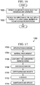
- aircraft manufacturing and service method 1700 may include specification and design 1702 of aircraft 1800 in Figure 18 and material procurement 1704.
- aircraft 1800 in Figure 18 During production, component and subassembly manufacturing 1706 and system integration 1708 of aircraft 1800 in Figure 18 takes place. Thereafter, aircraft 1800 in Figure 18 may go through certification and delivery 1710 in order to be placed in service 1712. While in service 1712 by a customer, aircraft 1800 in Figure 18 is scheduled for routine maintenance and service 1714, which may include modification, reconfiguration, refurbishment, and other maintenance or service.
- Each of the processes of aircraft manufacturing and service method 1700 may be performed or carried out by a system integrator, a third party, and/or an operator.
- the operator may be a customer.
- a system integrator may include, without limitation, any number of aircraft manufacturers and major-system subcontractors
- a third party may include, without limitation, any number of vendors, subcontractors, and suppliers
- an operator may be an airline, a leasing company, a military entity, a service organization, and so on.
- aircraft 1800 is produced by aircraft manufacturing and service method 1700 in Figure 17 and may include airframe 1802 with plurality of systems 1804 and interior 1806.
- systems 1804 include one or more of propulsion system 1808, electrical system 1810, hydraulic system 1812, and environmental system 1814. Any number of other systems may be included.
- propulsion system 1808 includes one or more of propulsion system 1808, electrical system 1810, hydraulic system 1812, and environmental system 1814. Any number of other systems may be included.
- electrical system 1810 electrical system 1810
- hydraulic system 1812 hydraulic system
- environmental system 1814 any number of other systems may be included.
- an aerospace example is shown, different advantageous embodiments may be applied to other industries, such as the automotive industry.
- Apparatuses and methods embodied herein may be employed during at least one of the stages of aircraft manufacturing and service method 1700 in Figure 17 .
- components or subassemblies produced in component and subassembly manufacturing 1706 in Figure 17 may be fabricated or manufactured in a manner similar to components or subassemblies produced while aircraft 1800 is in service 1712 in Figure 17 .
- one or more apparatus embodiments, method embodiments, or a combination thereof may be utilized during production stages, such as component and subassembly manufacturing 1706 and system integration 1708 in Figure 17 .
- One or more apparatus embodiments, method embodiments, or a combination thereof may be utilized while aircraft 1800 is in service 1712 and/or during maintenance and service 1714 in Figure 17 .
- the use of a number of the different advantageous embodiments may substantially expedite the assembly of and/or reduce the cost of aircraft 1800.
- motion restrictor system 106 in Figure 1 may be added to inlets for aircraft 1800 during stages, such as component and subassembly manufacturing 1706 and/or during maintenance and service 1714.
- the use of motion restrictor system 106 may reduce maintenance for aircraft 1800.
- inlets for aircraft 1800 may be replaced less frequently when using motion restrictor system 106.
Description
- The present disclosure relates generally to aircraft and, in particular, to aircraft engines. Still more particularly, the present disclosure relates to a method and apparatus for reducing vibrations in an inlet of an aircraft engine.
- An aircraft engine is a component of a propulsion system for an aircraft that generates mechanical power to move the aircraft. Aircraft engines may take many different forms, depending on the type of aircraft in which they are used. For example, aircraft may use engines in the form of a turboprop, a turbojet, a turbofan, and other suitable types of engines.
- Many commercial aircraft use jet engines in the form of a turbofan. A turbofan is a type of jet engine that provides thrust using a combination of a ducted fan and a jet exhaust nozzle. These types of engines have rotating shafts or spools.
- Vibrations from these and other components may be undesirable with respect to the ride and comfort of passengers or may affect the durability of engine parts. For example, vibrations may also limit the speed at which the components may rotate. Further, when vibrations occur, maintenance for these types of engines may be needed more often than desired.
- Therefore, it would be advantageous to have a method and apparatus that takes into account at least some of the issues discussed above, as well as possibly of other issues.
-
FR 2942457 - According to an aspect, there is provided an apparatus as defined in claim 1. According to another aspect, there is provided a method for reducing vibrations in an inlet of an aircraft engine as defined in claim 13. In one advantageous embodiment, an apparatus comprises a first wall and a plurality of longitudinal members. The first wall is for an inlet of an aircraft engine. The plurality of longitudinal members connects the first wall to a structure for the aircraft engine. The plurality of longitudinal members has an orientation configured to reduce motion in the inlet, wherein the motion reduced in the inlet is in an axial direction of the aircraft engine.
- In an example, a motion restrictor system for an inlet of an aircraft engine comprises a structure, an inlet, and a plurality of longitudinal members. The structure is in the aircraft engine. The inlet is connected to the aircraft engine. The plurality of longitudinal members has first ends connected to a wall of the inlet and second ends connected to the structure. Motion in an axial direction in the wall of the inlet caused by the structure is reduced.
- In yet another advantageous embodiment, a method for reducing vibrations in an inlet of an aircraft engine is provided. The aircraft engine is operated such that vibrations are generated. The vibrations in the inlet are reduced with a plurality of longitudinal members connecting a first wall of the inlet to a second wall of a structure for the aircraft engine. The plurality of longitudinal members has an orientation configured to reduce the vibration in the inlet, wherein the motion reduced in the inlet is in an axial direction of the aircraft engine.
- The features, functions, and advantages can be achieved independently in various embodiments of the present disclosure or may be combined in yet other embodiments in which further details can be seen with reference to the following description and drawings.
- The novel features believed characteristic of the advantageous embodiments are set forth in the appended claims. The advantageous embodiments, however, as well as a preferred mode of use, further objectives, and advantages thereof, will best be understood by reference to the following detailed description of an advantageous embodiment of the present disclosure when read in conjunction with the accompanying drawings, wherein:
-
Figure 1 is an illustration of a block diagram of a motion restriction environment in which an advantageous embodiment may be implemented; -
Figure 2 is an illustration of an aircraft in accordance with an advantageous embodiment; -
Figure 3 is a more-detailed illustration of an engine in accordance with an advantageous embodiment; -
Figure 4 is an illustration of an engine in accordance with an advantageous embodiment; -
Figure 5 is a view of an inlet in accordance with an advantageous embodiment; -
Figure 6 is an exposed view of an inlet in accordance with an advantageous embodiment; -
Figure 7 is an illustration of a longitudinal member connected to a wall of an inlet in accordance with an advantageous embodiment; -
Figure 8 is a more-detailed illustration of a portion of a longitudinal member connected to a wall of an inlet in accordance with an advantageous embodiment; -
Figure 9 is another view of a longitudinal member with a connector system in accordance with an advantageous embodiment; -
Figure 10 is an illustration of a longitudinal member in accordance with an advantageous embodiment; -
Figure 11 is another view of a longitudinal member in accordance with an advantageous embodiment; -
Figure 12 is another illustration of an inlet with a motion restriction system in accordance with an advantageous embodiment; -
Figure 13 is a more-detailed view of a portion of an inlet with a longitudinal member in accordance with an advantageous embodiment; -
Figure 14 is another illustration of an inlet with a motion restriction system in accordance with an advantageous embodiment; -
Figure 15 is an illustration of an inlet with a motion restriction system in accordance with an advantageous embodiment; -
Figure 16 is an illustration of a flowchart of a process for reducing vibrations in an inlet of an aircraft engine in accordance with an advantageous embodiment; -
Figure 17 is an illustration of an aircraft manufacturing and service method in accordance with an advantageous embodiment; and -
Figure 18 is an illustration of an aircraft in which an advantageous embodiment may be implemented. - The different advantageous embodiments recognize and take into account one or more different considerations. For example, the different advantageous embodiments recognize and take into account that the rotating shaft and spools may contribute to the vibrations. These vibrations may extend into the housing and through other components in the engine.
- The different advantageous embodiments recognize and take into account that different mechanisms are currently used to reduce vibrations in a radial direction. In other words, mechanisms are currently available for reducing vibrations in a direction substantially perpendicular to an axis extending through the rotating shaft in the engine.
- The different advantageous embodiments also recognize and take into account that other types of vibrations may be present that may be undesirable. For example, the different advantageous embodiments recognize and take into account that the different portions of an inlet attached to the housing of an engine may move back and forth in an axial direction. This motion may be caused by vibrations in other parts of the engine, such as the fan and spools. This axial direction is in the same direction as an axis extending through a shaft of the engine.
- The different advantageous embodiments recognize and take into account that this type of vibration in the axial direction may cause inconsistencies to occur in the inlet more quickly than desired. As a result, the inlet may need maintenance, rework, or replacement more often than desired.
- Thus, the different advantageous embodiments recognize and take into account that reducing vibrations for the inlet in an axial direction may be desirable.
- In one advantageous embodiment, an apparatus comprises a first wall for an inlet of an aircraft engine. The apparatus also comprises a plurality of longitudinal members. The plurality of longitudinal members connects the first wall to a second wall of the structure for the aircraft engine. The plurality of longitudinal members has an orientation configured to reduce motion, such as vibrations, in the first wall. These walls may take the form of bulkheads in some illustrative examples.
- With reference now to the figures and particularly with reference to
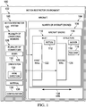
Figure 1 , an illustration of a block diagram of a motion restrictor environment is depicted in accordance with an advantageous embodiment. In this illustrative example,motion restrictor environment 100 includesaircraft 102.Aircraft 102 includes number ofaircraft engines 104. As used herein, a number, when used with reference to an item, means one or more items. For example, a number of engines may be one or more engines. - In these illustrative examples,
motion restrictor system 106 may be implemented inaircraft engine 108 in any of number ofaircraft engines 104.Motion restrictor system 106 may be installed or added toaircraft engine 108 at different times. For example,motion restrictor system 106 may be included inaircraft engine 108 during construction ofaircraft engine 108. In another illustrative example,motion restrictor system 106 may be added toaircraft engine 108 during maintenance, refurbishment, or other operations with respect toaircraft engine 108. - In these illustrative examples,
motion restrictor system 106 may be used to reducemotion 112 ininlet 110 ofaircraft engine 108.Inlet 110 is attached to structure 114. -
Motion 116 generated bystructure 114 during operation ofaircraft engine 108 may causemotion 112 ininlet 110. In these illustrative examples,motion 112 andmotion 116 take the form of vibrations. -
Structure 114 may be any structure to whichinlet 110 is connected. For example,structure 114 may befan case 118 foraircraft engine 108. In these illustrative examples,motion 112 may causeinlet 110 to form inconsistencies or require replacement more often than desired. - As a result,
motion 112 may be reduced in these illustrative examples through the use ofmotion restrictor system 106.Motion restrictor system 106 comprises plurality oflongitudinal members 120. Plurality oflongitudinal members 120 connectsfirst wall 122 ininlet 110 tosecond wall 124 instructure 114. A longitudinal member in plurality oflongitudinal members 120 is a structure that is configured to extend from one component to another component, such asfirst wall 122 tosecond wall 124, and connect the components to each other. - As used herein, a first component "connected to" a second component means that the first component can be connected directly or indirectly to the second component. For example, the first component may be
first wall 122, and the second component may besecond wall 124. In other words, additional components may be present between the first component and the second component. In this illustrative example, plurality oflongitudinal members 120 are examples of additional components that connect the first component,first wall 122, to the second component,second wall 124. The first component is considered to be indirectly connected to the second component when one or more additional components are present between the two components. When the first component is directly connected to the second component, no additional components are present between the two components. - In these illustrative examples, plurality of
longitudinal members 120 may be indirectly connected tosecond wall 124. For example, plurality ofconnectors 126 may connect plurality oflongitudinal members 120 tosecond wall 124. As another example, plurality oflongitudinal members 120 may be connected to another structure ininlet 110 that may be connected tosecond wall 124. These structures may take the form of bulkheads in some illustrative examples. - In these illustrative examples, plurality of
longitudinal members 120 hasshape 128 andorientation 130. At least one ofshape 128 andorientation 130 is configured to reducemotion 112 ofinlet 110.Motion 112 may be used when plurality oflongitudinal members 120 are connected tofirst wall 122 andsecond wall 124. In particular,motion 112 may be reduced forfirst wall 122 ininlet 110. - As used herein, the phrase "at least one of", when used with a list of items, means different combinations of one or more of the listed items may be used and only one of each item in the list may be needed. For example, "at least one of item A, item B, and item C" may include, for example, without limitation, item A or item A and item B. This example also may include item A, item B, and item C, or item B and item C.
- In these illustrative examples,
shape 128 for plurality oflongitudinal members 120 may take a number of different forms. For example, any longitudinal member may have any geometric shape, such as an I-beam, a beam, a T-section, a web, a C-channel, a rod, a cylinder, a closed structure, an open section, a closed section, and/or other suitable shapes. -
Orientation 130 is anaxial direction 132.Axial direction 132 is in the same direction asaxis 134 extending centrally throughaircraft engine 108 in these illustrative examples. - Further, plurality of
longitudinal members 120 is comprised ofmaterial 136.Material 136 also may be selected as one that may aid in reducingmotion 112 forfirst wall 122. Further,material 136 may be selected as one that may withstand operational vibration ofaircraft engine 108 for a desired period of time without causing any of plurality oflongitudinal members 120 to changeshape 128 in an undesired manner.Material 136 may be, for example, at least one of aluminum, a composite material, titanium, steel, a metal alloy, and other suitable types of material. - Further, in these illustrative examples, plurality of
connectors 126 are connected tofirst wall 122 andsecond wall 124 inconfiguration 138. In the depicted examples, plurality ofconnectors 126 is spaced apart from each other by substantially an equal amount of spacing. In other words, two longitudinal members may be spaced apart at a distance that is substantially equal to the spacing between two other longitudinal members in the plurality of longitudinal members. The spacing may be around the circumference of the inlet. For example, if four longitudinal members are present in plurality oflongitudinal members 120,configuration 138 may be a spacing of about 90 degrees aroundinlet 110. - The illustration of motion
restrictor environment 100 inFigure 1 is not meant to imply physical or architectural limitations to a manner in which an advantageous embodiment may be implemented. Other components in addition to and/or in place of the ones illustrated may be used. Some components may be unnecessary. Also, the blocks are presented to illustrate some functional components. One or more of these blocks may be combined and/or divided into different blocks when implemented in an advantageous embodiment. - For example, in still other illustrative examples, plurality of
longitudinal members 120 may comprise two longitudinal members, three longitudinal members, five longitudinal members, eight longitudinal members, or some other suitable number of longitudinal members. Further,configuration 138 may not include having substantially the same distance between longitudinal members in plurality oflongitudinal members 120, depending on the design ofinlet 110. In some cases, features or structures ininlet 110 may result in a different spacing for some longitudinal members within plurality oflongitudinal members 120. - In this manner,
motion restrictor system 106 may reducemotion 112. The reduction ofmotion 112 may reduce a development of inconsistencies ininlet 110. Further, maintenance ininlet 110 may be reduced with the use ofmotion restrictor system 106 withinlet 110. - With reference to
Figures 2-15 , illustrations of physical implementations for components, such as an aircraft, an engine, an inlet, and components for a motion restrictor system are depicted in accordance with an advantageous embodiment. In these illustrative examples, the different components shown in these figures may be combined with the components inFigure 2 , using components inFigure 2 , or a combination of the two. Additionally, some of the components shown in these figures may be illustrative examples of how components in block form inFigure 1 may be implemented as physical structures. - Turning next to
Figure 2 , an illustration of an aircraft is depicted in accordance with an advantageous embodiment.Aircraft 200 is an example of a physical implementation foraircraft 102 illustrated in block form inFigure 1 . - As depicted,
aircraft 200 haswing 202 andwing 204 attached tofuselage 206.Aircraft 200 also hashorizontal stabilizer 208,horizontal stabilizer 210 andvertical stabilizer 212.Engine 214 is attached towing 204, andengine 216 is attached towing 202.Engine 214 andengine 216 are examples of physical implementations for number ofaircraft engines 104 illustrated in block form inFigure 1 . - In these illustrative examples, one or more advantageous embodiments may be implemented in
engine 214 andengine 216. In particular,motion restrictor system 106 inFigure 1 may be implemented for use with at least one ofinlet 218 forengine 214 andinlet 220 forengine 216. - With reference now to
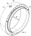
Figure 3 , a more-detailed illustration of an engine is depicted in accordance with an advantageous embodiment. In this figure, a partially-exposed view ofengine 214 is illustrated. - As depicted,
inlet 218 is connected tofan case 300 forengine 214 in this exposed view.Fan case 300 is an example of a physical implementation forfan case 118 illustrated in block form inFigure 1 . - In these illustrative examples, undesired motion may occur in
axial direction 302 with respect toinlet 218.Axial direction 302 is a direction corresponding to the direction ofaxis 304. In these illustrative examples,inlet 218 may be connected tofan case 300 at locations, such aslocation 306. Motion infan case 300 may be inaxial direction 302, which causes movement of components ininlet 218 inaxial direction 302. - With reference next to
Figure 4 , another illustration of an engine is depicted in accordance with an advantageous embodiment. In this illustrative example,engine 214 is shown in an exploded view. - With reference next to
Figure 5 , an illustration of a view of an inlet is depicted in accordance with an advantageous embodiment. In this illustrative example,wall 500 ofinlet 218 is seen in this perspective view.Wall 500 may be attached tofan case 300 inFigure 3 . - In these illustrative examples, a motion restrictor system may be implemented for use with
inlet 218 to reduce motion ininlet 218. In particular, motion may be reduced forwall 502. The motion restrictor system may be implemented inside ofinlet 218 undercover 504. Cover 504 may take the form of an outer cowl forinlet 218. - With reference next to
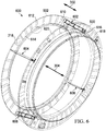
Figure 6 , an illustration of an exposed view of an inlet is depicted in accordance with an advantageous embodiment. In this illustrative example,motion restrictor system 600 is shown connected toinlet 218. - As depicted in this illustrative example,
motion restrictor system 600 compriseslongitudinal member 602,longitudinal member 604, longitudinal member 606, and longitudinal member 608 in these illustrative examples. These longitudinal members are spaced apart from each other with substantially the same space. - For example, the longitudinal members may be spaced apart from each other about 90 degrees with respect to
axis 304 extending centrally throughinlet 218.Longitudinal members wall 502 inaxial direction 302. - In these illustrative examples, the orientation of
longitudinal members axial direction 302. Instead, these longitudinal members are oriented such that they extend in a direction that has an angle with respect toaxis 304. The angle for the longitudinal members is selected to reduce motion ofinlet 218 inaxial direction 302. - In these examples, the motion takes the form of vibrations that may travel through a structure, such as
fan case 300, toinlet 218 during the operation ofengine 214. In these illustrative examples,longitudinal members - In this example, the longitudinal members are angled in orientation in
inlet 218 with respect toaxis 304. More specifically, end 610 oflongitudinal member 602 is shown as being connected closer toouter edge 612 as compared toinner edge 614 ofwall 502. This location may be selected based on where the most motion is expected inwall 502. The selection of the location is made to reduce motion inwall 502 as much as possible. -
End 616 oflongitudinal member 602 is located closer toinner edge 618 ofwall 500 as compared toouter edge 620 ofwall 500. This location is selected such thatend 616 may be connected to another structure inengine 214. In this example, the structure is selected as one that is the source of the motion that occurs ininlet 218. This structure may be, for example,fan case 300 inFigure 3 . - With reference now to
Figure 7 , an illustration of a longitudinal member connected to a wall of an inlet is depicted in accordance with an advantageous embodiment. In this illustrative example, end 610 oflongitudinal member 602 is connected to wall 502 ofinlet 218. In particular, end 610 oflongitudinal member 602 is connected indirectly to wall 502 throughflange 702 extending fromwall 502 ofinlet 218. - In these illustrative examples, end 610 of
longitudinal member 602 may be connected toflange 702 in a number of different ways. For example, end 610 may be connected to flange 702 by one of a weld, a fastener, and/or other suitable mechanisms. As another illustrative example, a fastening or connector system also may be used to connectend 610 toflange 702. Also, end 610 may be connected directly towall 502. - With reference now to
Figure 8 , a more-detailed illustration of a portion of a longitudinal member connected to a wall of an inlet is depicted in accordance with an advantageous embodiment. In this illustrative example, end 800 may be connected to a structure (not shown) in the engine, such as an engine case. - In this illustrative example, the connection to the structure may be made indirectly through
wall 500 ofinlet 218. Further, the connection may be made usingconnector system 802.Connector system 802 is connected to end 616 oflongitudinal member 602. In turn,connector system 802 touches surface 804 ofwall 500. - Fasteners may be used to connect
connector system 802 to bothwall 500 and tofan case 300 inFigure 3 . In this manner, end 616 oflongitudinal member 602 may be connected tofan case 300. This connection is an indirect connection throughwall 500 in the illustrative example. In this example, a fastener may be placed though opening 806 inconnector system 802. - With reference now to
Figure 9 , another view of a longitudinal member with a connector system is depicted in accordance with an advantageous embodiment. In this illustrative example, opening 900 also may be seen in addition to opening 806 inconnector system 802.Opening 806 andopening 900 may receive fasteners that connectconnector system 802 tofan case 300 inFigure 3 in these illustrative examples. In particular, the connection may be to a wall (not shown) offan case 300. - With reference now to
Figure 10 , an illustration of a longitudinal member is depicted in accordance with an advantageous embodiment. In this illustrative example,longitudinal member 602 is I-beam 1000. I-beam 1000 comprises substantiallyplanar structure 1002 withflange 1004 andflange 1006 onside 1008 andside 1010, respectively, of substantiallyplanar structure 1002. In addition, I-beam 1000 also may includeflange 1012,flange 1014, andflange 1016, which extends substantially perpendicular fromsurface 1018 of substantiallyplanar structure 1002. - With reference now to
Figure 11 , another view of a longitudinal member is depicted in accordance with an advantageous embodiment. In this illustrative example,flange 1100,flange 1102, andflange 1104 can be seen extending substantially perpendicular fromsurface 1106 of substantiallyplanar structure 1002. In the depicted examples, end 610 and end 616 are tapered. The ends may have this shape to reduce weight. The shape may also be selected to maintain a desired level of strength for longitudinal member 606 inFigure 6 . - With reference now to
Figure 12 , another illustration of an inlet with a motion restrictor system is depicted in accordance with an advantageous embodiment.Inlet 1200 is an example of an implementation forinlet 110 inFigure 1 . - In this illustrative example,
inlet 1200 is connected tofan case 300.Inlet 1200 may be used in place ofinlet 218 inFigure 2 .Inlet 1200 is shown in an exposed view in this depicted example. -
Inlet 1200 haswall 1203 andwall 1204. These walls also may be referred to as bulkheads in some cases.Wall 1204 ofinlet 1200 is connected tofan case 300. - Additionally,
inlet 1200 also hasmotion restrictor system 1206 in this illustrative example. Four longitudinal members connectwall 1203 ofinlet 1200 tofan case 300, two of which can be seen in this view.Longitudinal member 1208 andlongitudinal member 1210 can be seen in about a two o'clock and about a four o'clock position. Additionally, two longitudinal members are present in about a ten o'clock and about an eight o'clock position that are not seen in this view. - Further, additional longitudinal members may be present that connect
wall 1203 tofan case 300. In this illustrative example,wall 1204 is located between the longitudinal members andfan case 300. - In this illustrative example,
longitudinal member 1212 can be seen in about a one o'clock position. Of course, additional longitudinal members also may be present at the eleven o'clock position and/or other positions, depending on the particular implementation. These longitudinalmembers connecting wall 1203 towall 1204 may provide an additional reduction in motion ininlet 1200 in addition to longitudinalmembers connecting wall 1203 tofan case 300. - With reference now to
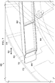
Figure 13 , a more-detailed view of a portion of an inlet with a longitudinal member is depicted in accordance with an advantageous embodiment. In this illustrative example, a more-detailed view oflongitudinal member 1208 withininlet 1200 is depicted in accordance with an advantageous embodiment. - As can be seen,
longitudinal member 1208 is shown within interior 1300 ofinlet 1200. In this illustrative example,cover 1302 is illustrated oninlet 1200. - In this illustrative example,
end 1304 oflongitudinal member 1208 is connected to wall 1203 ofinlet 1200.End 1306 oflongitudinal member 1208 is connected to inlet attachring 1308 located onwall 1309 offan case 300. As depicted, this connection is an indirect connection viawall 1204 ofinlet 1200. - As can be seen,
longitudinal member 1208 extends alongdirection 1310. However, withininlet 1200,longitudinal member 1208 has a diagonal or angled position with respect towall 1203 andwall 1204. - In these illustrative examples, this angled-position
longitudinal member 1208 extends indirection 1310.Direction 1310 has an angle with respect toaxis 1311 ofinlet 1200. In other words, the angled position selected to reduce motion ofinlet 1200 is in the direction ofaxis 1311 ofinlet 1200. - In particular,
end 1304 oflongitudinal member 1208 is connected closer toouter edge 1313 ofwall 1203 thaninner edge 1314 ofwall 1203 forinlet 1200.End 1306 oflongitudinal member 1208 is connected toinner edge 1314 ofwall 1204.Inner edge 1314 is located approximate toouter edge 1316 ofwall 1204. - With reference now to
Figure 14 , another illustration of an inlet with a motion restrictor system is depicted in accordance with an advantageous embodiment. In this illustrative example, an exposed view ofinlet 1400 is depicted.Inlet 1400 is an example of another implementation ofinlet 110 inFigure 1 and may be used in place ofinlet 218 inFigure 2 . - As depicted,
inlet 1400 haswall 1402 andwall 1404.Inlet 1400 is connected tofan case 300. In this illustrative example, a portion ofmotion restrictor system 1408 is depicted in this view.Motion restrictor system 1408 includeslongitudinal member 1410. - In this illustrative example,
longitudinal member 1410 takes the form ofrod 1412.End 1414 oflongitudinal member 1410 is connected towall 1402, whileend 1416 oflongitudinal member 1410 is connected tofan case 300.End 1414 andend 1416 are tapered ends in this example. As depicted,end 1414 is connected to wall 1402 usingconnector system 1418. -
End 1416 is connected tofan case 300 usingconnector system 1420. In these illustrative examples,connector system 1418 andconnector system 1420 are lugs with pins. Additionally,longitudinal member 1422 is depicted and connectswall 1402 towall 1404 ininlet 1400. - With reference now to
Figure 15 , an illustration of an inlet with a motion restrictor system is depicted in accordance with an advantageous embodiment.Inlet 1500 is another example of an implementation forinlet 110 inFigure 1 .Inlet 1500 may be used in place ofinlet 218 inFigure 2 . - In this illustrative example, an exposed view of
inlet 1500 is depicted. In this illustrative example,inlet 1500 haswall 1502 andwall 1504.Inlet 1500 is connected tofan case 300. - As depicted, a portion of
motion restrictor system 1508 is shown. In this view ofinlet 1500,longitudinal member 1510 andlongitudinal member 1512 are seen withininlet 1500.Longitudinal member 1510 andlongitudinal member 1512connect wall 1502 ofinlet 1500 to a structure in the form offan case 300. In these illustrative examples,longitudinal member 1510 andlongitudinal member 1512 take the form of substantially planar members. In particular,longitudinal member 1510 andlongitudinal member 1512 may take the form of webs. - Thus, the different illustrations of motion restrictor systems used with inlets for aircraft engines in
Figures 2-15 may reduce motion in the inlets. In particular, vibrations in walls of the inlets may be reduced. The illustrations of inlets and motion restrictor systems in these figures are not meant to imply physical or architectural limitations to the manner in which different motion restrictor systems may be implemented in accordance with an advantageous embodiment. - For example, longitudinal members have been shown in the form of I-beams, rods, and substantially planar members. Other types of longitudinal members may be used. For example, some longitudinal members may have a cross-section in the shape of a T, a triangle, a hexagon, and/or some other suitable open or closed shapes. Further, different types of longitudinal members may be used in the same motion restrictor system. For example, one motion restrictor system may include two longitudinal members in the form of I-beams and two longitudinal members in the form of rods.
- With reference now to
Figure 16 , a flowchart of a process for reducing vibrations in an inlet of an aircraft engine is depicted in accordance with an advantageous embodiment. In this illustrative example,motion restrictor system 106 may be implemented inaircraft engine 108. - The process begins by operating an aircraft engine such that vibrations are generated (operation 1600). Thereafter, the process reduces the vibrations in the inlet with a plurality of longitudinal members in the motion restrictor system (operation 1602), with the process terminating thereafter. This process may occur each time an aircraft engine is operated with
motion restrictor system 106 installed in the inlet of the engine. - Advantageous embodiments of the disclosure may be described in the context of aircraft manufacturing and
service method 1700 as shown inFigure 17 andaircraft 1800 as shown inFigure 18 . Turning first toFigure 17 , an illustration of an aircraft manufacturing and service method is depicted in accordance with an advantageous embodiment. During pre-production, aircraft manufacturing andservice method 1700 may include specification anddesign 1702 ofaircraft 1800 inFigure 18 andmaterial procurement 1704. - During production, component and
subassembly manufacturing 1706 andsystem integration 1708 ofaircraft 1800 inFigure 18 takes place. Thereafter,aircraft 1800 inFigure 18 may go through certification anddelivery 1710 in order to be placed inservice 1712. While inservice 1712 by a customer,aircraft 1800 inFigure 18 is scheduled for routine maintenance andservice 1714, which may include modification, reconfiguration, refurbishment, and other maintenance or service. - Each of the processes of aircraft manufacturing and
service method 1700 may be performed or carried out by a system integrator, a third party, and/or an operator. In these examples, the operator may be a customer. For the purposes of this description, a system integrator may include, without limitation, any number of aircraft manufacturers and major-system subcontractors; a third party may include, without limitation, any number of vendors, subcontractors, and suppliers; and an operator may be an airline, a leasing company, a military entity, a service organization, and so on. - With reference now to
Figure 18 , an illustration of an aircraft is depicted in which an advantageous embodiment may be implemented. In this example,aircraft 1800 is produced by aircraft manufacturing andservice method 1700 inFigure 17 and may includeairframe 1802 with plurality ofsystems 1804 and interior 1806. Examples ofsystems 1804 include one or more ofpropulsion system 1808,electrical system 1810,hydraulic system 1812, andenvironmental system 1814. Any number of other systems may be included. Although an aerospace example is shown, different advantageous embodiments may be applied to other industries, such as the automotive industry. - Apparatuses and methods embodied herein may be employed during at least one of the stages of aircraft manufacturing and
service method 1700 inFigure 17 . - In one illustrative example, components or subassemblies produced in component and
subassembly manufacturing 1706 inFigure 17 may be fabricated or manufactured in a manner similar to components or subassemblies produced whileaircraft 1800 is inservice 1712 inFigure 17 . As yet another example, one or more apparatus embodiments, method embodiments, or a combination thereof may be utilized during production stages, such as component andsubassembly manufacturing 1706 andsystem integration 1708 inFigure 17 . One or more apparatus embodiments, method embodiments, or a combination thereof may be utilized whileaircraft 1800 is inservice 1712 and/or during maintenance andservice 1714 inFigure 17 . The use of a number of the different advantageous embodiments may substantially expedite the assembly of and/or reduce the cost ofaircraft 1800. - For example,
motion restrictor system 106 inFigure 1 may be added to inlets foraircraft 1800 during stages, such as component andsubassembly manufacturing 1706 and/or during maintenance andservice 1714. The use ofmotion restrictor system 106 may reduce maintenance foraircraft 1800. For example, inlets foraircraft 1800 may be replaced less frequently when usingmotion restrictor system 106. - The description of the different advantageous embodiments has been presented for purposes of illustration and description and is not intended to be exhaustive or limited to the embodiments in the form disclosed. Many modifications and variations will be apparent to those of ordinary skill in the art.
- Further, different advantageous embodiments may provide different advantages as compared to other advantageous embodiments. The embodiment or embodiments selected are chosen and described in order to best explain the principles of the embodiments, the practical application, and to enable others of ordinary skill in the art to understand the disclosure for various embodiments with various modifications as are suited to the particular use contemplated.
Claims (14)
- An apparatus comprising:a first wall (122) for an inlet (110, 218, 220, 1200, 1400, 1500) of an aircraft engine (108, 214,216); a structure (114) for the aircraft engine;a plurality of longitudinal members (120) connecting the first wall to the structure (114) for the aircraft engine,characterised in that the plurality of longitudinal members has an orientation (130) configured to reduce motion (112, 116) in the first wall (122) for the inlet; and in that the motion reduced in the first wall (122) for the inlet is in an axial direction of the aircraft engine.
- The apparatus of claim 1, wherein the plurality of longitudinal members (120) is connected to an upper section of the first wall (122) for the inlet (110, 218, 220, 1200, 1400, 1500).
- The apparatus of claim 1, wherein the plurality of longitudinal members (120) has spacing that is substantially equal around a circumference around the inlet (110, 218, 220, 1200, 1400, 1500) of the aircraft engine (108, 214, 216).
- The apparatus of claim 1, wherein the plurality of longitudinal members (120) is connected to a second wall (124) of the structure (114) for the aircraft engine (108, 214, 216).
- The apparatus of claim 1, wherein the structure (114) is a source of the motion (112, 116).
- The apparatus of claim 1, wherein the structure (114) is a fan case (118, 300) for the aircraft engine (108, 214, 216).
- The apparatus of claim 1 further comprising:a connector system (802) configured to connect an end (616) of a longitudinal member (602, 604, 606, 608) in the plurality of longitudinal members (120) to the structure (114).
- The apparatus of claim 1, wherein the first wall (122) is a flange (702) for the inlet (110, 218, 220, 1200, 1400, 1500).
- The apparatus of claim 1, wherein the plurality of longitudinal members (120) is from three longitudinal members to eight longitudinal members.
- The apparatus of claim 1, wherein a longitudinal member (602, 604, 606, 608) is selected from one of an I-beam, a beam, a rod, a cylinder, a web, and a substantially planar member.
- The apparatus of claim 1, wherein the plurality of longitudinal members (120) is comprised of a material selected from one of aluminum, steel, titanium, and a composite material.
- The apparatus of claim 1, wherein the plurality of longitudinal members (120) has first ends ( 1414) connected to a wall (122) of the inlet (110, 218, 220, 1200, 1400, 1500) and second ends (1416) connected to a fan case (118, 300).
- A method for reducing vibrations in an inlet (110, 218, 220, 1200, 1400, 1500) of an aircraft engine (108, 214, 216), the method comprising:operating the aircraft engine such that the vibrations are generated;reducing the vibrations in the inlet with a plurality of longitudinal members (120) connecting a first wall (122) of the inlet to a second wall (124) of a structure (114) for the aircraft engine, wherein the plurality of longitudinal members has an orientation configured to reduce the vibrations in the inlet;and wherein the motion reduced in the inlet is in an axial direction of the aircraft engine.
- The method of claim 14, wherein motion (112, 116) is reduced at the first wall (122) of the inlet (110, 218, 220, 1200, 1400, 1500).
Applications Claiming Priority (1)
| Application Number | Priority Date | Filing Date | Title |
|---|---|---|---|
| PCT/US2011/050447 WO2013032490A1 (en) | 2011-09-02 | 2011-09-02 | Motion restrictor system for an aircraft engine |
Publications (2)
| Publication Number | Publication Date |
|---|---|
| EP2750972A1 EP2750972A1 (en) | 2014-07-09 |
| EP2750972B1 true EP2750972B1 (en) | 2017-08-02 |
Family
ID=44651999
Family Applications (1)
| Application Number | Title | Priority Date | Filing Date |
|---|---|---|---|
| EP11757492.1A Active EP2750972B1 (en) | 2011-09-02 | 2011-09-02 | Motion restrictor system for an aircraft engine |
Country Status (3)
| Country | Link |
|---|---|
| EP (1) | EP2750972B1 (en) |
| ES (1) | ES2645342T3 (en) |
| WO (1) | WO2013032490A1 (en) |
Families Citing this family (2)
| Publication number | Priority date | Publication date | Assignee | Title |
|---|---|---|---|---|
| CN107667057B (en) * | 2015-05-29 | 2021-01-26 | 庞巴迪公司 | Method and system for aligning a propulsion system and vehicle with such propulsion alignment |
| FR3126964B1 (en) * | 2021-09-13 | 2023-08-04 | Safran Nacelles | Nacelle for an aircraft propulsion system comprising an access space closed off by a cowling with tangential clamping |
Family Cites Families (4)
| Publication number | Priority date | Publication date | Assignee | Title |
|---|---|---|---|---|
| US4044973A (en) * | 1975-12-29 | 1977-08-30 | The Boeing Company | Nacelle assembly and mounting structures for a turbofan jet propulsion engine |
| FR2906568B1 (en) * | 2006-10-02 | 2012-01-06 | Aircelle Sa | DEPOSITABLE AIR INTAKE STRUCTURE FOR TURBOJET NACELLE. |
| FR2933070B1 (en) * | 2008-06-25 | 2010-08-20 | Snecma | PROPULSIVE AIRCRAFT SYSTEM |
| FR2942457B1 (en) * | 2009-02-24 | 2011-04-22 | Snecma | TURBOREACTOR NACELLE WITH REMOVABLE AIR INTAKE STRUCTURE |
-
2011
- 2011-09-02 EP EP11757492.1A patent/EP2750972B1/en active Active
- 2011-09-02 ES ES11757492.1T patent/ES2645342T3/en active Active
- 2011-09-02 WO PCT/US2011/050447 patent/WO2013032490A1/en active Application Filing
Non-Patent Citations (1)
| Title |
|---|
| None * |
Also Published As
| Publication number | Publication date |
|---|---|
| ES2645342T3 (en) | 2017-12-05 |
| WO2013032490A1 (en) | 2013-03-07 |
| EP2750972A1 (en) | 2014-07-09 |
Similar Documents
| Publication | Publication Date | Title |
|---|---|---|
| EP2639159B1 (en) | Engine mounting system for an aircraft | |
| EP2502824B1 (en) | Joint sealing system | |
| US8523516B2 (en) | Bypass turbojet engine nacelle | |
| EP2895392B1 (en) | Metallic sandwich structure having small bend radius | |
| JP5823519B2 (en) | Multi-digit port box joint | |
| Das et al. | Composite materials and their damage detection using AI techniques for aerospace application: A brief review | |
| WO2009048713A1 (en) | Ceramic heat shield | |
| US9656761B2 (en) | Lipskin for a nacelle and methods of making the same | |
| US9643733B2 (en) | Fire seal for an aircraft | |
| US11022071B2 (en) | Load distribution panel assembly, system and method | |
| US20190219000A1 (en) | Acoustic attenuation system for nacelle structures and method therefor | |
| US8016227B2 (en) | Non-handed engine cowl doors for fuselage mounted turbine engines | |
| EP2750972B1 (en) | Motion restrictor system for an aircraft engine | |
| EP2865878B1 (en) | Gimbal pin for jet propulsion system | |
| EP3705394B1 (en) | Auxiliary power unit enclosure and method of making the same | |
| US20230365247A1 (en) | Strut assembly and method for coupling an engine to a wing of an aircraft | |
| US11946413B2 (en) | Inlet bulkheads for large diameter aircraft engines | |
| Taminger | NASA High-Rate Aerostructures Technology Plans | |
| Lennard | Design Features of the CF6 Engine Thrust Reverser and Spoiler | |
| CN114790943A (en) | Air inlet duct of aircraft engine nacelle and aircraft engine nacelle | |
| Ford et al. | Aero Engine Design |
Legal Events
| Date | Code | Title | Description |
|---|---|---|---|
| PUAI | Public reference made under article 153(3) epc to a published international application that has entered the european phase |
Free format text: ORIGINAL CODE: 0009012 |
|
| 17P | Request for examination filed |
Effective date: 20140307 |
|
| AK | Designated contracting states |
Kind code of ref document: A1 Designated state(s): AL AT BE BG CH CY CZ DE DK EE ES FI FR GB GR HR HU IE IS IT LI LT LU LV MC MK MT NL NO PL PT RO RS SE SI SK SM TR |
|
| DAX | Request for extension of the european patent (deleted) | ||
| REG | Reference to a national code |
Ref country code: DE Ref legal event code: R079 Ref document number: 602011040172 Country of ref document: DE Free format text: PREVIOUS MAIN CLASS: B64D0027000000 Ipc: B64D0033020000 |
|
| GRAP | Despatch of communication of intention to grant a patent |
Free format text: ORIGINAL CODE: EPIDOSNIGR1 |
|
| RIC1 | Information provided on ipc code assigned before grant |
Ipc: B64D 33/02 20060101AFI20170110BHEP Ipc: B64D 27/00 20060101ALI20170110BHEP Ipc: B64D 27/26 20060101ALI20170110BHEP |
|
| INTG | Intention to grant announced |
Effective date: 20170130 |
|
| RAP1 | Party data changed (applicant data changed or rights of an application transferred) |
Owner name: THE BOEING COMPANY |
|
| GRAS | Grant fee paid |
Free format text: ORIGINAL CODE: EPIDOSNIGR3 |
|
| GRAJ | Information related to disapproval of communication of intention to grant by the applicant or resumption of examination proceedings by the epo deleted |
Free format text: ORIGINAL CODE: EPIDOSDIGR1 |
|
| GRAL | Information related to payment of fee for publishing/printing deleted |
Free format text: ORIGINAL CODE: EPIDOSDIGR3 |
|
| GRAR | Information related to intention to grant a patent recorded |
Free format text: ORIGINAL CODE: EPIDOSNIGR71 |
|
| GRAA | (expected) grant |
Free format text: ORIGINAL CODE: 0009210 |
|
| INTC | Intention to grant announced (deleted) | ||
| INTG | Intention to grant announced |
Effective date: 20170620 |
|
| AK | Designated contracting states |
Kind code of ref document: B1 Designated state(s): AL AT BE BG CH CY CZ DE DK EE ES FI FR GB GR HR HU IE IS IT LI LT LU LV MC MK MT NL NO PL PT RO RS SE SI SK SM TR |
|
| REG | Reference to a national code |
Ref country code: CH Ref legal event code: EP Ref country code: AT Ref legal event code: REF Ref document number: 914145 Country of ref document: AT Kind code of ref document: T Effective date: 20170815 |
|
| REG | Reference to a national code |
Ref country code: IE Ref legal event code: FG4D |
|
| REG | Reference to a national code |
Ref country code: DE Ref legal event code: R096 Ref document number: 602011040172 Country of ref document: DE |
|
| REG | Reference to a national code |
Ref country code: FR Ref legal event code: PLFP Year of fee payment: 7 |
|
| REG | Reference to a national code |
Ref country code: ES Ref legal event code: FG2A Ref document number: 2645342 Country of ref document: ES Kind code of ref document: T3 Effective date: 20171205 |
|
| REG | Reference to a national code |
Ref country code: NL Ref legal event code: MP Effective date: 20170802 |
|
| REG | Reference to a national code |
Ref country code: AT Ref legal event code: MK05 Ref document number: 914145 Country of ref document: AT Kind code of ref document: T Effective date: 20170802 |
|
| REG | Reference to a national code |
Ref country code: LT Ref legal event code: MG4D |
|
| PG25 | Lapsed in a contracting state [announced via postgrant information from national office to epo] |
Ref country code: LT Free format text: LAPSE BECAUSE OF FAILURE TO SUBMIT A TRANSLATION OF THE DESCRIPTION OR TO PAY THE FEE WITHIN THE PRESCRIBED TIME-LIMIT Effective date: 20170802 Ref country code: NO Free format text: LAPSE BECAUSE OF FAILURE TO SUBMIT A TRANSLATION OF THE DESCRIPTION OR TO PAY THE FEE WITHIN THE PRESCRIBED TIME-LIMIT Effective date: 20171102 Ref country code: SE Free format text: LAPSE BECAUSE OF FAILURE TO SUBMIT A TRANSLATION OF THE DESCRIPTION OR TO PAY THE FEE WITHIN THE PRESCRIBED TIME-LIMIT Effective date: 20170802 Ref country code: FI Free format text: LAPSE BECAUSE OF FAILURE TO SUBMIT A TRANSLATION OF THE DESCRIPTION OR TO PAY THE FEE WITHIN THE PRESCRIBED TIME-LIMIT Effective date: 20170802 Ref country code: AT Free format text: LAPSE BECAUSE OF FAILURE TO SUBMIT A TRANSLATION OF THE DESCRIPTION OR TO PAY THE FEE WITHIN THE PRESCRIBED TIME-LIMIT Effective date: 20170802 Ref country code: HR Free format text: LAPSE BECAUSE OF FAILURE TO SUBMIT A TRANSLATION OF THE DESCRIPTION OR TO PAY THE FEE WITHIN THE PRESCRIBED TIME-LIMIT Effective date: 20170802 Ref country code: NL Free format text: LAPSE BECAUSE OF FAILURE TO SUBMIT A TRANSLATION OF THE DESCRIPTION OR TO PAY THE FEE WITHIN THE PRESCRIBED TIME-LIMIT Effective date: 20170802 |
|
| PG25 | Lapsed in a contracting state [announced via postgrant information from national office to epo] |
Ref country code: IS Free format text: LAPSE BECAUSE OF FAILURE TO SUBMIT A TRANSLATION OF THE DESCRIPTION OR TO PAY THE FEE WITHIN THE PRESCRIBED TIME-LIMIT Effective date: 20171202 Ref country code: BG Free format text: LAPSE BECAUSE OF FAILURE TO SUBMIT A TRANSLATION OF THE DESCRIPTION OR TO PAY THE FEE WITHIN THE PRESCRIBED TIME-LIMIT Effective date: 20171102 Ref country code: GR Free format text: LAPSE BECAUSE OF FAILURE TO SUBMIT A TRANSLATION OF THE DESCRIPTION OR TO PAY THE FEE WITHIN THE PRESCRIBED TIME-LIMIT Effective date: 20171103 Ref country code: LV Free format text: LAPSE BECAUSE OF FAILURE TO SUBMIT A TRANSLATION OF THE DESCRIPTION OR TO PAY THE FEE WITHIN THE PRESCRIBED TIME-LIMIT Effective date: 20170802 Ref country code: PL Free format text: LAPSE BECAUSE OF FAILURE TO SUBMIT A TRANSLATION OF THE DESCRIPTION OR TO PAY THE FEE WITHIN THE PRESCRIBED TIME-LIMIT Effective date: 20170802 Ref country code: RS Free format text: LAPSE BECAUSE OF FAILURE TO SUBMIT A TRANSLATION OF THE DESCRIPTION OR TO PAY THE FEE WITHIN THE PRESCRIBED TIME-LIMIT Effective date: 20170802 |
|
| PG25 | Lapsed in a contracting state [announced via postgrant information from national office to epo] |
Ref country code: DK Free format text: LAPSE BECAUSE OF FAILURE TO SUBMIT A TRANSLATION OF THE DESCRIPTION OR TO PAY THE FEE WITHIN THE PRESCRIBED TIME-LIMIT Effective date: 20170802 Ref country code: RO Free format text: LAPSE BECAUSE OF FAILURE TO SUBMIT A TRANSLATION OF THE DESCRIPTION OR TO PAY THE FEE WITHIN THE PRESCRIBED TIME-LIMIT Effective date: 20170802 Ref country code: CZ Free format text: LAPSE BECAUSE OF FAILURE TO SUBMIT A TRANSLATION OF THE DESCRIPTION OR TO PAY THE FEE WITHIN THE PRESCRIBED TIME-LIMIT Effective date: 20170802 |
|
| REG | Reference to a national code |
Ref country code: CH Ref legal event code: PL |
|
| REG | Reference to a national code |
Ref country code: DE Ref legal event code: R097 Ref document number: 602011040172 Country of ref document: DE |
|
| PG25 | Lapsed in a contracting state [announced via postgrant information from national office to epo] |
Ref country code: SM Free format text: LAPSE BECAUSE OF FAILURE TO SUBMIT A TRANSLATION OF THE DESCRIPTION OR TO PAY THE FEE WITHIN THE PRESCRIBED TIME-LIMIT Effective date: 20170802 Ref country code: SK Free format text: LAPSE BECAUSE OF FAILURE TO SUBMIT A TRANSLATION OF THE DESCRIPTION OR TO PAY THE FEE WITHIN THE PRESCRIBED TIME-LIMIT Effective date: 20170802 Ref country code: MC Free format text: LAPSE BECAUSE OF FAILURE TO SUBMIT A TRANSLATION OF THE DESCRIPTION OR TO PAY THE FEE WITHIN THE PRESCRIBED TIME-LIMIT Effective date: 20170802 Ref country code: EE Free format text: LAPSE BECAUSE OF FAILURE TO SUBMIT A TRANSLATION OF THE DESCRIPTION OR TO PAY THE FEE WITHIN THE PRESCRIBED TIME-LIMIT Effective date: 20170802 |
|
| PLBE | No opposition filed within time limit |
Free format text: ORIGINAL CODE: 0009261 |
|
| STAA | Information on the status of an ep patent application or granted ep patent |
Free format text: STATUS: NO OPPOSITION FILED WITHIN TIME LIMIT |
|
| REG | Reference to a national code |
Ref country code: IE Ref legal event code: MM4A |
|
| REG | Reference to a national code |
Ref country code: BE Ref legal event code: MM Effective date: 20170930 |
|
| PG25 | Lapsed in a contracting state [announced via postgrant information from national office to epo] |
Ref country code: LU Free format text: LAPSE BECAUSE OF NON-PAYMENT OF DUE FEES Effective date: 20170902 |
|
| 26N | No opposition filed |
Effective date: 20180503 |
|
| PG25 | Lapsed in a contracting state [announced via postgrant information from national office to epo] |
Ref country code: IE Free format text: LAPSE BECAUSE OF NON-PAYMENT OF DUE FEES Effective date: 20170902 Ref country code: LI Free format text: LAPSE BECAUSE OF NON-PAYMENT OF DUE FEES Effective date: 20170930 Ref country code: CH Free format text: LAPSE BECAUSE OF NON-PAYMENT OF DUE FEES Effective date: 20170930 |
|
| PG25 | Lapsed in a contracting state [announced via postgrant information from national office to epo] |
Ref country code: SI Free format text: LAPSE BECAUSE OF FAILURE TO SUBMIT A TRANSLATION OF THE DESCRIPTION OR TO PAY THE FEE WITHIN THE PRESCRIBED TIME-LIMIT Effective date: 20170802 Ref country code: BE Free format text: LAPSE BECAUSE OF NON-PAYMENT OF DUE FEES Effective date: 20170930 |
|
| REG | Reference to a national code |
Ref country code: FR Ref legal event code: PLFP Year of fee payment: 8 |
|
| PG25 | Lapsed in a contracting state [announced via postgrant information from national office to epo] |
Ref country code: MT Free format text: LAPSE BECAUSE OF NON-PAYMENT OF DUE FEES Effective date: 20170902 |
|
| PG25 | Lapsed in a contracting state [announced via postgrant information from national office to epo] |
Ref country code: HU Free format text: LAPSE BECAUSE OF FAILURE TO SUBMIT A TRANSLATION OF THE DESCRIPTION OR TO PAY THE FEE WITHIN THE PRESCRIBED TIME-LIMIT; INVALID AB INITIO Effective date: 20110902 |
|
| PG25 | Lapsed in a contracting state [announced via postgrant information from national office to epo] |
Ref country code: CY Free format text: LAPSE BECAUSE OF NON-PAYMENT OF DUE FEES Effective date: 20170802 |
|
| PG25 | Lapsed in a contracting state [announced via postgrant information from national office to epo] |
Ref country code: MK Free format text: LAPSE BECAUSE OF FAILURE TO SUBMIT A TRANSLATION OF THE DESCRIPTION OR TO PAY THE FEE WITHIN THE PRESCRIBED TIME-LIMIT Effective date: 20170802 |
|
| PG25 | Lapsed in a contracting state [announced via postgrant information from national office to epo] |
Ref country code: TR Free format text: LAPSE BECAUSE OF FAILURE TO SUBMIT A TRANSLATION OF THE DESCRIPTION OR TO PAY THE FEE WITHIN THE PRESCRIBED TIME-LIMIT Effective date: 20170802 |
|
| PG25 | Lapsed in a contracting state [announced via postgrant information from national office to epo] |
Ref country code: PT Free format text: LAPSE BECAUSE OF FAILURE TO SUBMIT A TRANSLATION OF THE DESCRIPTION OR TO PAY THE FEE WITHIN THE PRESCRIBED TIME-LIMIT Effective date: 20170802 |
|
| PG25 | Lapsed in a contracting state [announced via postgrant information from national office to epo] |
Ref country code: AL Free format text: LAPSE BECAUSE OF FAILURE TO SUBMIT A TRANSLATION OF THE DESCRIPTION OR TO PAY THE FEE WITHIN THE PRESCRIBED TIME-LIMIT Effective date: 20170802 |
|
| P01 | Opt-out of the competence of the unified patent court (upc) registered |
Effective date: 20230516 |
|
| PGFP | Annual fee paid to national office [announced via postgrant information from national office to epo] |
Ref country code: IT Payment date: 20230921 Year of fee payment: 13 Ref country code: GB Payment date: 20230927 Year of fee payment: 13 |
|
| PGFP | Annual fee paid to national office [announced via postgrant information from national office to epo] |
Ref country code: FR Payment date: 20230925 Year of fee payment: 13 Ref country code: DE Payment date: 20230927 Year of fee payment: 13 |
|
| PGFP | Annual fee paid to national office [announced via postgrant information from national office to epo] |
Ref country code: ES Payment date: 20231002 Year of fee payment: 13 |