EP3279425A1 - Excavation tool - Google Patents
Excavation tool Download PDFInfo
- Publication number
- EP3279425A1 EP3279425A1 EP16772760.1A EP16772760A EP3279425A1 EP 3279425 A1 EP3279425 A1 EP 3279425A1 EP 16772760 A EP16772760 A EP 16772760A EP 3279425 A1 EP3279425 A1 EP 3279425A1
- Authority
- EP
- European Patent Office
- Prior art keywords
- tip
- excavation
- tool
- main body
- tool main
- Prior art date
- Legal status (The legal status is an assumption and is not a legal conclusion. Google has not performed a legal analysis and makes no representation as to the accuracy of the status listed.)
- Ceased
Links
Images


Classifications
-
- E—FIXED CONSTRUCTIONS
- E21—EARTH OR ROCK DRILLING; MINING
- E21B—EARTH OR ROCK DRILLING; OBTAINING OIL, GAS, WATER, SOLUBLE OR MELTABLE MATERIALS OR A SLURRY OF MINERALS FROM WELLS
- E21B10/00—Drill bits
- E21B10/46—Drill bits characterised by wear resisting parts, e.g. diamond inserts
- E21B10/56—Button-type inserts
-
- E—FIXED CONSTRUCTIONS
- E21—EARTH OR ROCK DRILLING; MINING
- E21B—EARTH OR ROCK DRILLING; OBTAINING OIL, GAS, WATER, SOLUBLE OR MELTABLE MATERIALS OR A SLURRY OF MINERALS FROM WELLS
- E21B10/00—Drill bits
- E21B10/60—Drill bits characterised by conduits or nozzles for drilling fluids
Definitions
- the present invention relates to an excavation tool in which an excavation tip is attached to the outer periphery of a tip surface of a tool main body to be rotated about an axis.
- Patent Document 1 discloses an excavation tool.
- this excavation tool the direction of implantation of a button-shaped and cemented carbide-based blade (excavation tip) on its outermost side into a bit holder (tool main body) is inclined outwards with respect to the vertical axis (axial line) of a bit and tilted in the same direction as the rotation direction of the bit (tool rotation direction).
- This excavation tool prevents breakage and the like by avoiding the bending stress that acts on the excavation tip as a result of rotation of the tool main body during excavation.
- Patent Document 1 Japanese Examined Utility Model Application, Second Publication No. S63-040544
- the excavation performance of the excavation tool is restored by regrinding of its blade edge once the excavation tip wears to some extent.
- this type of regrinding is performed with the axis of rotation of a regrinding wheel placed perpendicularly to the tip centerline of the excavation tip.
- the axis of rotation of the regrinding wheel is placed with the axis of the tool main body used as a reference.
- the present invention has been made in view of the above-described circumstances, and an object thereof is to provide an excavation tool which is capable of improving regrinding workability even if its excavation tip is inclined to an outer peripheral side of its main body and a tool rotation direction side as described above.
- an excavation tip is attached to an outer peripheral portion of a tip surface of a tool main body to be rotated about an axis, the excavation tip is inclined such that the excavation tip is directed toward an outer peripheral side of the tool main body and a tool rotation direction side as a centerline of the tip is directed toward a tip side in an axial direction, and a planar seat surface perpendicular to the tip centerline is formed in the outer peripheral portion of the tip surface of the tool main body such that the seat surface is adjacent to at least the tool rotation direction side of an attachment portion for the excavation tip.
- the tip centerline of the excavation tip is inclined such that it is directed toward the tool rotation direction side as it is directed toward the tip side in the axial direction as is the case with the excavation tool that is disclosed in Patent Document 1. Accordingly, the bending stress that acts on the excavation tip can be alleviated.
- the planar seat surface perpendicular to the tip centerline of the excavation tip is formed such that it is adjacent to the attachment portion for the excavation tip in the outer peripheral portion of the tip surface of the tool main body. Accordingly, when regrinding of the excavation tip is performed, the regrinding can be performed with accuracy by the axis of rotation of a regrinding wheel being placed with the seat surface used as a reference.
- the seat surface is formed such that it is adjacent to at least the tool rotation direction side of the attachment portion for the excavation tip, the seat surface is inclined to the rear end side of the tool main body in the axial direction from the attachment portion toward the outer peripheral side of the tool main body and the tool rotation direction side. Accordingly, a wide space can be ensured for the outer peripheral side of the blade edge of the excavation tip and the tool rotation direction side. Accordingly, wear of the tool main body can be suppressed, dropping of the excavation tip can be prevented by the cuttings being efficiently discharged via this space, and excavation can be performed with stability for a long period of time.
- a cuttings discharge flute open to the seat surface on the tool rotation direction side of the attachment portion for the excavation tip is formed in the outer peripheral portion of the tool main body. Then, the cuttings discharged to the space on the tool rotation direction side of the blade edge of the excavation tip as described above can be more efficiently discharged from the discharge flute and wear of the tool main body can be suppressed to a larger extent.
- the excavation tip attached to the outer peripheral portion of the tip surface of the tool main body as described above is placed such that it overlaps in the axial direction with a part forming a maximum outer diameter in the tip portion of the tool main body, the part forming the maximum outer diameter in the tip portion of the tool main body can be protected by the excavation tip from contact with the inner periphery of an excavation hole.
- the progress of wear of the outer periphery of the tip portion of the tool main body can be suppressed. Accordingly, early dropping of the excavation tip attached to the outer peripheral portion of the tip surface of the tool main body that is attributable to wear of the tip portion of the tool main body can be prevented and the life of the tool can be further extended.
- a long-life excavation tool can be provided because defects and the like can be prevented by a blade edge of an excavation tip being reground with accuracy with the bending stress that acts on the excavation tip suppressed.
- a tool main body 1 according to the present embodiment is formed from a steel material or the like and has a substantially bottomed cylindrical shape about an axis O. Its bottomed portion is a tip portion (right side part in FIGS. 4 and 5 ), and a female screw portion 2 is formed on the inner periphery of its cylindrical portion (skirt portion) that is its rear end portion (left side part in FIG. 5 ).
- This excavation tool excavates the ground with excavation tips 3 attached to the tip portion by means of a rotational force toward a tool rotation direction T about the axis O transmitted from an excavation device via an excavation rod connected to the female screw portion 2 and thrust and a striking force toward the tip side in the axis O-direction.
- the section of the outer peripheral surface of the tip portion of the tool main body 1 that is along the axis O is large in diameter in a concave curve shape toward the tip side from the rear end side in the axis O-direction. Then, the section of the outer peripheral surface of the tip portion of the tool main body 1 is formed such that it is large in diameter in the shape of a conical surface about the axis O.
- the outer peripheral portion of the tip surface of the tool main body 1 except for its seat surfaces (described later) is gauge surface 4 that have the shape of a conical surface about the axis O, decrease in diameter toward the tip side, and are inclined with respect to the axis O at a steeper angle than the conical surface which is formed by the tip side of the outer peripheral surface of the tip portion.
- the inner peripheral portion of the tip surface on the inner peripheral side that is inside the gauge surfaces 4 is a planar face surface 5 perpendicular to the axis O.
- the excavation tips 3 are attached to the gauge surfaces 4 and the face surface 5.
- the excavation tip 3 is formed from a material that is harder than the tool main body 1 such as a cemented carbide.
- the excavation tip 3 is a button tip at which its rear end portion that has the shape of a column about a tip centerline C and a blade edge in its tip portion that has a hemispherical shape and the same diameter as the rear end portion which has its center on the tip centerline C are integrally sintered with each other.
- a plurality of (eight in the present embodiment) recessed holes with a circular section is formed in the face surface 5 as attachment portions 6 for the excavation tips 3.
- the recessed holes are spaced apart from one another in a circumferential direction and a radial direction in parallel to the axis O, that is, perpendicularly to the face surface 5.
- the excavation tips 3 are attached to the attachment portions 6 by their rear end portions being inserted into the attachment portions 6, the blade edges being allowed to protrude from the face surface 5, and the excavation tips 3 being implanted by brazing, press-fitting, or the like.
- the plurality of excavation tips 3 attached to the face surface 5 in this manner is arranged such that they cover substantially the entire face surface 5 with the rotation trajectories of the respective blade edges about the axis O overlapping.
- a plurality of (nine in the present embodiment) recessed holes with a circular section is formed in the gauge surfaces 4 as attachment portions 7 spaced apart from one another in the circumferential direction.
- the excavation tips 3 are attached to the attachment portions 7 by their rear end portions being inserted into the attachment portions 7, the blade edges being allowed to protrude from the gauge surfaces 4, and the excavation tips 3 being implanted by brazing, press-fitting, or the like.
- the attachment portions 7 in the gauge surfaces 4 are arranged such that centerlines of the recessed holes are positioned on a plane P that is parallel to a plane including the axis O of the tool main body 1 and positioned slightly on the opposite side to that plane in the tool rotation direction T and extend to the outer peripheral side of the tool main body 1 toward the tip side in the axis O-direction.
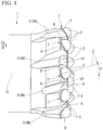
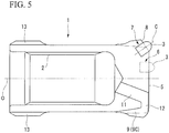
- the tip centerlines C of the excavation tips 3 attached to the attachment portions 7 as a result of the above are inclined toward the outer peripheral side of the tool main body 1 as shown in FIG. 5 and are inclined toward the tool rotation direction T side as shown in FIG. 4 toward the tip side in the axis O-direction.
- the inclination angle of the tip centerline C of the excavation tip 3 attached to the attachment portion 7 in the gauge surface 4 in the tool rotation direction T preferably ranges from 5° to 20° as an inclination angle ⁇ with respect to the axis O at a time when it is seen from the direction of a straight line perpendicular to the axis O and passing through the center of the hemisphere which is formed by the blade edge of the excavation tip 3 as shown in FIG. 4 . More preferably, the inclination angle ranges from 10° to 15°.
- the seat surfaces 8 are adjacent to the respective attachment portions 7.
- the seat surface 8 according to the present embodiment extends toward the tool rotation direction T side from the side of the attachment portion 7 that is slightly opposite to the tool rotation direction T, its intersection ridge portion with respect to the gauge surface 4 on the opposite side to the tool rotation direction T has a semi-elliptical shape, the seat surface 8 extends such that it partially cuts out the outer peripheral portion of the face surface 5 on the tool rotation direction T side, and the attachment portion 7 as the recessed hole is open to the seat surface 8.
- a maximum outer diameter that is formed by the rotation trajectory about the axis O of the excavation tip 3 attached to the attachment portion 7 in the gauge surface 4 is set to be larger than the maximum outer diameter of the tool main body 1.
- the diameter of a cylinder circumscribed about the excavation tip 3 on the gauge surface 4 about the axis O exceeds the diameter of the outer peripheral edge of the gauge surface 4 as the maximum outer diameter of the tool main body 1 (diameter of a circle where an intersection ridge with respect to the gauge surfaces 4 and a part that is large in diameter with a conical surface shape toward the tip side in the axis O-direction in the outer peripheral surface of the tip portion of the tool main body 1 is positioned).
- the blade edge of the excavation tip 3 on the gauge surface 4 slightly protrudes from the tool main body 1 as shown in FIG. 2 .
- the seat surface 8, to which the attachment portion 7 as the recessed hole is open is inclined to the rear end side in the axis O-direction from the attachment portion 7 toward the outer peripheral side of the tool main body 1 and the tool rotation direction T side and intersects with the outer peripheral edge of the gauge surface 4 with the maximum outer diameter in the tip portion of the tool main body 1 as described later, and formation of the attachment portion 7 reaches a position slightly beyond the outer peripheral edge of the gauge surface 4 on the rear end side in the axis O-direction as shown in FIGS. 3 and 4 . Accordingly, the excavation tip 3 attached to the attachment portion 7 also slightly overlaps with the outer peripheral edge of the gauge surface 4, which is the part that forms the maximum outer diameter in the tip portion of the tool main body 1, in the direction of the axis O.
- Cuttings discharge flutes 9 that intersect with and are open to the respective seat surfaces 8 on the tool rotation direction T side of the respective attachment portions 7 in the gauge surfaces 4 are formed in the outer peripheral surface of the tip portion of the tool main body 1 formed such that its diameter is large toward the tip side from the rear end side in the axis O-direction as described above.
- the discharge flutes 9 are inclined in the same direction as the inclination of the tip centerlines C in side view such that they are directed toward the side opposite to the tool rotation direction T toward the rear end side in the axis O-direction.
- first discharge flute 9A in which the number of the attachment portions 7 is nine, three sets of a first discharge flute 9A, a second discharge flute 9B, and a third discharge flute 9C are formed in this order toward the side opposite to the tool rotation direction T, the first discharge flute 9A being small in flute depth and flute length and the second discharge flute 9B and the third discharge flute 9C being large in flute depth and flute length.
- Wall surfaces 10 are formed on the tool rotation direction T side of the seat surfaces 8 to which the first discharge flute 9A and the second discharge flute 9B are open.
- the second discharge flute 9B is adjacent to the side of the first discharge flute 9A that is opposite to the tool rotation direction T.
- the wall surfaces 10 intersect with the seat surfaces 8 at an obtuse angle, extend toward the tip side in the axis O-direction toward the tool rotation direction T side, and intersect with the gauge surfaces 4 and the face surface 5.
- the wall surfaces 10 are inclined such that they are directed toward the rear end side in the axis O-direction while being slightly directed to the tool rotation direction T side toward the outer peripheral side of the tool main body 1.
- the first discharge flute 9A and the second discharge flute 9B intersect with and are open to the wall surfaces 10 as well.
- blow holes 11 are formed equidistantly in the circumferential direction in the tip portion of the tool main body 1. Toward the tip side in the axis O-direction from the middle portion of the bottom surface of the cylindrical portion (skirt portion) in the rear end portion, the blow holes 11 extend toward the outer peripheral side of the tool main body 1.
- Each of the blow holes 11 is open to the face surface 5 on the tool main body 1 inner peripheral side of the opening portion of the third discharge flute 9C in the gauge surface 4.
- Communicating flutes 12 with a U-shaped section are formed between the opening portions of the blow holes 11 in the face surface 5 and the opening portion of the third discharge flute 9C in the gauge surface 4 open to its outer peripheral side.
- the outer periphery of the rear end portion of the tool main body 1 is formed such that it is larger in diameter than the part between the tip portion and itself. Still, a maximum outer diameter of the larger-diameter rear end portion is set to be smaller than the diameter of the outer peripheral edge of the gauge surface 4 as the maximum outer diameter of the tool main body 1 described above.
- the concave flutes 13 are formed on the rear end side in the axis O-direction of the positions of the rear ends of the first to third discharge flutes 9A to 9C in the circumferential direction.
- the excavation tips 3 attached to the gauge surfaces 4, which are the outer peripheral portion of the tip surface of the tool main body 1, are inclined toward the outer peripheral side of the tool main body 1 and the tool rotation direction T side as their tip centerlines C are directed toward the tip side in the axis O-direction. Accordingly, the bending stress that is attributable to the rotational force in the tool rotation direction T can be received and alleviated as a compressive stress in the tip centerline C direction, and breakage of the excavation tips 3 and the like can be prevented.
- the planar seat surfaces 8, which are perpendicular to the tip centerlines C of the excavation tips 3 attached to the attachment portions 7, are formed such that they are adjacent to the attachment portions 7 for the excavation tips 3 on the gauge surfaces 4. Accordingly, when regrinding is performed after some wear of the excavation tips 3, the regrinding can be performed with accuracy, by the seat surfaces 8 being used as a reference, despite the positional relationship in which the tip centerlines C are twisted with respect to the axis O of the tool main body 1 to incline the tip centerlines C to the outer peripheral side of the tool main body 1 and the tool rotation direction T side. Specifically, the regrinding may be performed with the axis of rotation of a regrinding wheel not placed perpendicularly to the tip centerline C but placed in parallel to the seat surfaces 8.
- the excavation tool that has the configuration described above is capable of preventing distorted regrinding of the blade edges of the excavation tips 3 and ensuring a high level of defect resistance for the blade edges after the regrinding. Accordingly, breakage of the excavation tips 3 and the like attributable to the rotational force in the tool rotation direction T can be prevented as described above and the excavation tool can be provided as a long-life excavation tool that is capable of performing excavation with stability over a long period of time.
- the excavation tip 3 attached to the gauge surface 4 in the outer peripheral portion of the tip surface of the tool main body 1 overlaps with the outer peripheral edge of the gauge surface 4 as the part with the maximum outer diameter in the tip portion of the tool main body 1 in the direction of the axis O and placed such that its positioning reaches the rear end side in the axis O-direction that is slightly beyond the outer peripheral edge.
- the excavation tips 3 are arranged on the direct tool rotation direction T side of the outer peripheral edges of the gauge surfaces 4 left between the seat surfaces 8 and the discharge flutes 9.
- the outer peripheral edge of the gauge surface 4 that forms the maximum outer diameter in the tip portion of the tool main body 1 can be protected, by the excavation tip 3 itself, from contact with the inner periphery of an excavation hole excavated by the excavation tip 3 and wear of the tool main body 1 can be suppressed. Accordingly, early dropping of the excavation tips 3 implanted in the gauge surfaces 4 as the maximum outer diameter portions that is attributable to wear of the tool main body 1 can be prevented and the life of the tool can be further extended.
- the seat surface 8 is formed such that it is adjacent to at least the tool rotation direction T side of the attachment portion 7 in the gauge surface 4 in the outer peripheral portion of the tip surface of the tool main body 1.
- the tip centerline C of the excavation tip 3 attached to the attachment portion 7 in the gauge surface 4 is inclined to the outer peripheral side of the tool main body 1 and the tool rotation direction T side toward the tip side in the axis O-direction.
- the seat surface 8 perpendicular to the tip centerline C is inclined to the rear end side in the direction of the axis O.
- the cuttings that have been produced by the excavation tips 3 attached to the gauge surfaces 4 can be pushed out by the excavation tips 3 and rotation of the tool main body 1 and efficiently discharged from the space on the tool rotation direction T side and the outer peripheral side. Accordingly, staying of the cuttings on the seat surfaces 8 can be prevented and wear of the tool main body 1 that is attributable to the cuttings and results in early dropping of the excavation tips 3 can be prevented as well.
- the discharge flutes 9 are formed in the outer periphery of the tip portion of the tool main body 1 that is larger in diameter and the discharge flutes 9 are open to the seat surfaces 8 adjacent to the tool rotation direction T side of the attachment portions 7 in the gauge surfaces 4 as described above. Accordingly, the cuttings pushed out to the tool rotation direction T side by the blade edges of the excavation tips 3 in particular can be discharged from the discharge flutes 9 to the rear end side of the tool main body 1 and wear of the tool main body 1 attributable to the cuttings can be prevented with a high level of reliability.
- the cuttings discharge flutes 9 are inclined such that they are directed toward the side opposite to the tool rotation direction T toward the rear end side in the axis O-direction. Accordingly, the cuttings discharged to the discharge flutes 9 are pushed out to the rear end side of the tool main body 1 and discharged to a space between the excavation rod beyond the tool main body 1 on the rear end side and the excavation hole through the concave flutes 13 formed in the rear end portion of the tool main body 1 even larger in diameter. Accordingly, the cuttings discharged from the seat surfaces 8 to the discharge flutes 9 can be quickly removed from the space that is between the tool main body 1 and the excavation hole and resistance during excavation can be reduced.
- the direction of the inclination of the discharge flutes 9 is the same as the direction of the inclination of the tip centerlines C of the excavation tips 3 attached to the attachment portions 7 formed in the gauge surfaces 4 as described above. Accordingly, a relatively uniform thickness can be provided for the tool main body 1 between the attachment portions 7 formed as the recessed holes and the discharge flutes 9 adjacent thereto in their circumferential direction. Accordingly, early dropping of the excavation tips 3 attributable to wear resulting from the cuttings flowing through the discharge flutes 9 can be prevented.
- the third discharge flute 9C which is one of the discharge flutes 9 that is large in flute depth and flute length, communicates with the blow hole 11 formed in the tip portion of the tool main body 1 via the communicating flute 12 in the face surface 5.
- compressed air or the like supplied through the excavation rod is ejected from the blow hole 11 to the communicating flute 12.
- the cuttings discharged to the third discharge flute 9C can be pushed out to the rear end side. Accordingly, the present embodiment is capable of adding to the efficiency of cuttings discharge.
- the button tip with the blade edge that has the hemispherical shape is used as the excavation tip 3.
- the present invention can be applied to excavation tools in which a ballistic-type excavation tip with a blade edge that has the shape of a shell and a spike-type excavation tip with a blade edge that has a truncated cone-shaped rear end portion and a tip portion that has the shape of a hemisphere which is small in radius are attached to the attachment portions 6 and 7.
- tip centerline C of the excavation tip 3 attached to the attachment portion 6 in the face surface 5 may be inclined to the tool rotation direction T side toward the tip side in the axis O-direction as is the case with the excavation tool that is disclosed in Patent Document 1.
- a long-life excavation tool can be provided because defects and the like can be prevented by a blade edge of an excavation tip being reground with accuracy with the bending stress that acts on the excavation tip suppressed.
Landscapes
- Engineering & Computer Science (AREA)
- Life Sciences & Earth Sciences (AREA)
- Geology (AREA)
- Mining & Mineral Resources (AREA)
- Mechanical Engineering (AREA)
- Physics & Mathematics (AREA)
- Environmental & Geological Engineering (AREA)
- Fluid Mechanics (AREA)
- General Life Sciences & Earth Sciences (AREA)
- Geochemistry & Mineralogy (AREA)
- Earth Drilling (AREA)
- Percussive Tools And Related Accessories (AREA)
Abstract
Description
- The present invention relates to an excavation tool in which an excavation tip is attached to the outer periphery of a tip surface of a tool main body to be rotated about an axis.
- Priority is claimed on Japanese Patent Application No.
2015-077026, filed on April 3, 2015 -
Patent Document 1, for example, discloses an excavation tool. In this excavation tool, the direction of implantation of a button-shaped and cemented carbide-based blade (excavation tip) on its outermost side into a bit holder (tool main body) is inclined outwards with respect to the vertical axis (axial line) of a bit and tilted in the same direction as the rotation direction of the bit (tool rotation direction). This excavation tool prevents breakage and the like by avoiding the bending stress that acts on the excavation tip as a result of rotation of the tool main body during excavation. - [Patent Document 1] Japanese Examined Utility Model Application, Second Publication No.
S63-040544 - The excavation performance of the excavation tool is restored by regrinding of its blade edge once the excavation tip wears to some extent. In most cases, this type of regrinding is performed with the axis of rotation of a regrinding wheel placed perpendicularly to the tip centerline of the excavation tip. In general excavation tools in which the tip centerline is on a plane including the axis of the tool main body, the axis of rotation of the regrinding wheel is placed with the axis of the tool main body used as a reference.
- When the direction of implantation of the excavation tip into the tool main body is inclined outwards from the tool main body and in the tool rotation direction and the tip centerline of the excavation tip has a positional relationship in which it is twisted with respect to the axis of the tool main body as in the excavation tool that is disclosed in
Patent Document 1; however, it is difficult for the axis of rotation of the regrinding wheel to be accurately placed based on the axis of the tool main body as its reference. Accordingly, defects are likely to result from distorted regrinding of the blade edge of the excavation tip and the life of the excavation tool after the regrinding might be reduced. - The present invention has been made in view of the above-described circumstances, and an object thereof is to provide an excavation tool which is capable of improving regrinding workability even if its excavation tip is inclined to an outer peripheral side of its main body and a tool rotation direction side as described above.
- In an excavation tool according to an aspect of the present invention for achieving the object by solving the above-described problem, an excavation tip is attached to an outer peripheral portion of a tip surface of a tool main body to be rotated about an axis, the excavation tip is inclined such that the excavation tip is directed toward an outer peripheral side of the tool main body and a tool rotation direction side as a centerline of the tip is directed toward a tip side in an axial direction, and a planar seat surface perpendicular to the tip centerline is formed in the outer peripheral portion of the tip surface of the tool main body such that the seat surface is adjacent to at least the tool rotation direction side of an attachment portion for the excavation tip.
- In the excavation tool that has the configuration described above, the tip centerline of the excavation tip is inclined such that it is directed toward the tool rotation direction side as it is directed toward the tip side in the axial direction as is the case with the excavation tool that is disclosed in
Patent Document 1. Accordingly, the bending stress that acts on the excavation tip can be alleviated. The planar seat surface perpendicular to the tip centerline of the excavation tip is formed such that it is adjacent to the attachment portion for the excavation tip in the outer peripheral portion of the tip surface of the tool main body. Accordingly, when regrinding of the excavation tip is performed, the regrinding can be performed with accuracy by the axis of rotation of a regrinding wheel being placed with the seat surface used as a reference. Accordingly, distorted regrinding of a blade edge of the excavation tip that results in a higher likelihood of defects can be prevented despite the positional relationship in which the axis of the tool main body and the tip centerline are twisted with respect to each other and the life of the excavation tool can be extended. - When the excavation tip on the outermost side also is inclined in the tool rotation direction as in the case of the excavation tool that is disclosed in
Patent Document 1, cuttings (excavation scraps) crushed and produced by the excavation tip on the outermost side flow out such that they are guided to the tool rotation direction side along the inclination of the excavation tip. The excavation tip, however, is inclined such that it is covered by the tip surface of the tool main body on the tool rotation direction side, and thus the cuttings that flow out are unlikely to be discharged. The cuttings result in wear in the vicinity of the attachment portion for the excavation tip in particular in the outer peripheral portion of the tip surface of the tool main body and the outer peripheral surface. Then, the excavation tip might be dropped. - Once the seat surface is formed such that it is adjacent to at least the tool rotation direction side of the attachment portion for the excavation tip, the seat surface is inclined to the rear end side of the tool main body in the axial direction from the attachment portion toward the outer peripheral side of the tool main body and the tool rotation direction side. Accordingly, a wide space can be ensured for the outer peripheral side of the blade edge of the excavation tip and the tool rotation direction side. Accordingly, wear of the tool main body can be suppressed, dropping of the excavation tip can be prevented by the cuttings being efficiently discharged via this space, and excavation can be performed with stability for a long period of time.
- In this case, in particular, a cuttings discharge flute open to the seat surface on the tool rotation direction side of the attachment portion for the excavation tip is formed in the outer peripheral portion of the tool main body. Then, the cuttings discharged to the space on the tool rotation direction side of the blade edge of the excavation tip as described above can be more efficiently discharged from the discharge flute and wear of the tool main body can be suppressed to a larger extent.
- Once the excavation tip attached to the outer peripheral portion of the tip surface of the tool main body as described above is placed such that it overlaps in the axial direction with a part forming a maximum outer diameter in the tip portion of the tool main body, the part forming the maximum outer diameter in the tip portion of the tool main body can be protected by the excavation tip from contact with the inner periphery of an excavation hole. As a result, the progress of wear of the outer periphery of the tip portion of the tool main body can be suppressed. Accordingly, early dropping of the excavation tip attached to the outer peripheral portion of the tip surface of the tool main body that is attributable to wear of the tip portion of the tool main body can be prevented and the life of the tool can be further extended.
- As described above, with the present invention, a long-life excavation tool can be provided because defects and the like can be prevented by a blade edge of an excavation tip being reground with accuracy with the bending stress that acts on the excavation tip suppressed.
-
-
FIG. 1 is a perspective view showing an embodiment of the present invention. -
FIG. 2 is a front view in which the embodiment shown inFIG. 1 is viewed from a tip side in an axial direction. -
FIG. 3 is a side view in the X direction inFIG. 2 . -
FIG. 4 is a partial side view in the Y direction inFIG. 2 . -
FIG. 5 is a sectional view in the ZQZ direction inFIG. 2 . - An embodiment of the present invention is shown in
FIGS. 1 to 5 . A toolmain body 1 according to the present embodiment is formed from a steel material or the like and has a substantially bottomed cylindrical shape about an axis O. Its bottomed portion is a tip portion (right side part inFIGS. 4 and5 ), and afemale screw portion 2 is formed on the inner periphery of its cylindrical portion (skirt portion) that is its rear end portion (left side part inFIG. 5 ). This excavation tool excavates the ground withexcavation tips 3 attached to the tip portion by means of a rotational force toward a tool rotation direction T about the axis O transmitted from an excavation device via an excavation rod connected to thefemale screw portion 2 and thrust and a striking force toward the tip side in the axis O-direction. - The section of the outer peripheral surface of the tip portion of the tool
main body 1 that is along the axis O is large in diameter in a concave curve shape toward the tip side from the rear end side in the axis O-direction. Then, the section of the outer peripheral surface of the tip portion of the toolmain body 1 is formed such that it is large in diameter in the shape of a conical surface about the axis O. The outer peripheral portion of the tip surface of the toolmain body 1 except for its seat surfaces (described later) isgauge surface 4 that have the shape of a conical surface about the axis O, decrease in diameter toward the tip side, and are inclined with respect to the axis O at a steeper angle than the conical surface which is formed by the tip side of the outer peripheral surface of the tip portion. The inner peripheral portion of the tip surface on the inner peripheral side that is inside thegauge surfaces 4 is aplanar face surface 5 perpendicular to the axis O. - The
excavation tips 3 are attached to thegauge surfaces 4 and theface surface 5. Theexcavation tip 3 is formed from a material that is harder than the toolmain body 1 such as a cemented carbide. In the present embodiment, theexcavation tip 3 is a button tip at which its rear end portion that has the shape of a column about a tip centerline C and a blade edge in its tip portion that has a hemispherical shape and the same diameter as the rear end portion which has its center on the tip centerline C are integrally sintered with each other. - A plurality of (eight in the present embodiment) recessed holes with a circular section is formed in the
face surface 5 asattachment portions 6 for theexcavation tips 3. The recessed holes are spaced apart from one another in a circumferential direction and a radial direction in parallel to the axis O, that is, perpendicularly to theface surface 5. Theexcavation tips 3 are attached to theattachment portions 6 by their rear end portions being inserted into theattachment portions 6, the blade edges being allowed to protrude from theface surface 5, and theexcavation tips 3 being implanted by brazing, press-fitting, or the like. The plurality ofexcavation tips 3 attached to theface surface 5 in this manner is arranged such that they cover substantially theentire face surface 5 with the rotation trajectories of the respective blade edges about the axis O overlapping. - Likewise, a plurality of (nine in the present embodiment) recessed holes with a circular section is formed in the
gauge surfaces 4 asattachment portions 7 spaced apart from one another in the circumferential direction. Theexcavation tips 3 are attached to theattachment portions 7 by their rear end portions being inserted into theattachment portions 7, the blade edges being allowed to protrude from thegauge surfaces 4, and theexcavation tips 3 being implanted by brazing, press-fitting, or the like. Theattachment portions 7 in thegauge surfaces 4 are arranged such that centerlines of the recessed holes are positioned on a plane P that is parallel to a plane including the axis O of the toolmain body 1 and positioned slightly on the opposite side to that plane in the tool rotation direction T and extend to the outer peripheral side of the toolmain body 1 toward the tip side in the axis O-direction. - Accordingly, the tip centerlines C of the
excavation tips 3 attached to theattachment portions 7 as a result of the above are inclined toward the outer peripheral side of the toolmain body 1 as shown inFIG. 5 and are inclined toward the tool rotation direction T side as shown inFIG. 4 toward the tip side in the axis O-direction. The inclination angle of the tip centerline C of theexcavation tip 3 attached to theattachment portion 7 in thegauge surface 4 in the tool rotation direction T preferably ranges from 5° to 20° as an inclination angle θ with respect to the axis O at a time when it is seen from the direction of a straight line perpendicular to the axis O and passing through the center of the hemisphere which is formed by the blade edge of theexcavation tip 3 as shown inFIG. 4 . More preferably, the inclination angle ranges from 10° to 15°. - Planar seat surfaces 8, which are perpendicular to the tip centerlines C of the
excavation tips 3 attached to therespective attachment portions 7 in the gauge surfaces 4, are formed on the gauge surfaces 4 as the outer peripheral portion of the tip surface of the toolmain body 1. The seat surfaces 8 are adjacent to therespective attachment portions 7. Theseat surface 8 according to the present embodiment extends toward the tool rotation direction T side from the side of theattachment portion 7 that is slightly opposite to the tool rotation direction T, its intersection ridge portion with respect to thegauge surface 4 on the opposite side to the tool rotation direction T has a semi-elliptical shape, theseat surface 8 extends such that it partially cuts out the outer peripheral portion of theface surface 5 on the tool rotation direction T side, and theattachment portion 7 as the recessed hole is open to theseat surface 8. - In the present embodiment, a maximum outer diameter that is formed by the rotation trajectory about the axis O of the
excavation tip 3 attached to theattachment portion 7 in thegauge surface 4 is set to be larger than the maximum outer diameter of the toolmain body 1. In other words, in the present embodiment, the diameter of a cylinder circumscribed about theexcavation tip 3 on thegauge surface 4 about the axis O exceeds the diameter of the outer peripheral edge of thegauge surface 4 as the maximum outer diameter of the tool main body 1 (diameter of a circle where an intersection ridge with respect to the gauge surfaces 4 and a part that is large in diameter with a conical surface shape toward the tip side in the axis O-direction in the outer peripheral surface of the tip portion of the toolmain body 1 is positioned). When seen from the tip side in the axis O-direction, the blade edge of theexcavation tip 3 on thegauge surface 4 slightly protrudes from the toolmain body 1 as shown inFIG. 2 . - In the present embodiment, the
seat surface 8, to which theattachment portion 7 as the recessed hole is open, is inclined to the rear end side in the axis O-direction from theattachment portion 7 toward the outer peripheral side of the toolmain body 1 and the tool rotation direction T side and intersects with the outer peripheral edge of thegauge surface 4 with the maximum outer diameter in the tip portion of the toolmain body 1 as described later, and formation of theattachment portion 7 reaches a position slightly beyond the outer peripheral edge of thegauge surface 4 on the rear end side in the axis O-direction as shown inFIGS. 3 and4 . Accordingly, theexcavation tip 3 attached to theattachment portion 7 also slightly overlaps with the outer peripheral edge of thegauge surface 4, which is the part that forms the maximum outer diameter in the tip portion of the toolmain body 1, in the direction of the axis O. - Cuttings discharge
flutes 9 that intersect with and are open to therespective seat surfaces 8 on the tool rotation direction T side of therespective attachment portions 7 in the gauge surfaces 4 are formed in the outer peripheral surface of the tip portion of the toolmain body 1 formed such that its diameter is large toward the tip side from the rear end side in the axis O-direction as described above. The discharge flutes 9 are inclined in the same direction as the inclination of the tip centerlines C in side view such that they are directed toward the side opposite to the tool rotation direction T toward the rear end side in the axis O-direction. In the present embodiment, in which the number of theattachment portions 7 is nine, three sets of afirst discharge flute 9A, asecond discharge flute 9B, and athird discharge flute 9C are formed in this order toward the side opposite to the tool rotation direction T, thefirst discharge flute 9A being small in flute depth and flute length and thesecond discharge flute 9B and thethird discharge flute 9C being large in flute depth and flute length. - Wall surfaces 10 are formed on the tool rotation direction T side of the seat surfaces 8 to which the
first discharge flute 9A and thesecond discharge flute 9B are open. Thesecond discharge flute 9B is adjacent to the side of thefirst discharge flute 9A that is opposite to the tool rotation direction T. The wall surfaces 10 intersect with the seat surfaces 8 at an obtuse angle, extend toward the tip side in the axis O-direction toward the tool rotation direction T side, and intersect with the gauge surfaces 4 and theface surface 5. The wall surfaces 10 are inclined such that they are directed toward the rear end side in the axis O-direction while being slightly directed to the tool rotation direction T side toward the outer peripheral side of the toolmain body 1. Thefirst discharge flute 9A and thesecond discharge flute 9B intersect with and are open to the wall surfaces 10 as well. - In the present embodiment, three
blow holes 11 are formed equidistantly in the circumferential direction in the tip portion of the toolmain body 1. Toward the tip side in the axis O-direction from the middle portion of the bottom surface of the cylindrical portion (skirt portion) in the rear end portion, the blow holes 11 extend toward the outer peripheral side of the toolmain body 1. Each of the blow holes 11 is open to theface surface 5 on the toolmain body 1 inner peripheral side of the opening portion of thethird discharge flute 9C in thegauge surface 4. Communicatingflutes 12 with a U-shaped section are formed between the opening portions of the blow holes 11 in theface surface 5 and the opening portion of thethird discharge flute 9C in thegauge surface 4 open to its outer peripheral side. - In the present embodiment, the outer periphery of the rear end portion of the tool
main body 1 is formed such that it is larger in diameter than the part between the tip portion and itself. Still, a maximum outer diameter of the larger-diameter rear end portion is set to be smaller than the diameter of the outer peripheral edge of thegauge surface 4 as the maximum outer diameter of the toolmain body 1 described above. -
Concave flutes 13, which extend in parallel to the axis O, are formed at the larger-diameter part in the rear end portion of the toolmain body 1. Theconcave flutes 13 are formed on the rear end side in the axis O-direction of the positions of the rear ends of the first to third discharge flutes 9A to 9C in the circumferential direction. - In the excavation tool that has the configuration described above, the
excavation tips 3 attached to the gauge surfaces 4, which are the outer peripheral portion of the tip surface of the toolmain body 1, are inclined toward the outer peripheral side of the toolmain body 1 and the tool rotation direction T side as their tip centerlines C are directed toward the tip side in the axis O-direction. Accordingly, the bending stress that is attributable to the rotational force in the tool rotation direction T can be received and alleviated as a compressive stress in the tip centerline C direction, and breakage of theexcavation tips 3 and the like can be prevented. - In the excavation tool that has the configuration described above, the planar seat surfaces 8, which are perpendicular to the tip centerlines C of the
excavation tips 3 attached to theattachment portions 7, are formed such that they are adjacent to theattachment portions 7 for theexcavation tips 3 on the gauge surfaces 4. Accordingly, when regrinding is performed after some wear of theexcavation tips 3, the regrinding can be performed with accuracy, by the seat surfaces 8 being used as a reference, despite the positional relationship in which the tip centerlines C are twisted with respect to the axis O of the toolmain body 1 to incline the tip centerlines C to the outer peripheral side of the toolmain body 1 and the tool rotation direction T side. Specifically, the regrinding may be performed with the axis of rotation of a regrinding wheel not placed perpendicularly to the tip centerline C but placed in parallel to the seat surfaces 8. - Accordingly, the excavation tool that has the configuration described above is capable of preventing distorted regrinding of the blade edges of the
excavation tips 3 and ensuring a high level of defect resistance for the blade edges after the regrinding. Accordingly, breakage of theexcavation tips 3 and the like attributable to the rotational force in the tool rotation direction T can be prevented as described above and the excavation tool can be provided as a long-life excavation tool that is capable of performing excavation with stability over a long period of time. - In the present embodiment, the
excavation tip 3 attached to thegauge surface 4 in the outer peripheral portion of the tip surface of the toolmain body 1 overlaps with the outer peripheral edge of thegauge surface 4 as the part with the maximum outer diameter in the tip portion of the toolmain body 1 in the direction of the axis O and placed such that its positioning reaches the rear end side in the axis O-direction that is slightly beyond the outer peripheral edge. In addition, theexcavation tips 3 are arranged on the direct tool rotation direction T side of the outer peripheral edges of the gauge surfaces 4 left between the seat surfaces 8 and the discharge flutes 9. As a result, the outer peripheral edge of thegauge surface 4 that forms the maximum outer diameter in the tip portion of the toolmain body 1 can be protected, by theexcavation tip 3 itself, from contact with the inner periphery of an excavation hole excavated by theexcavation tip 3 and wear of the toolmain body 1 can be suppressed. Accordingly, early dropping of theexcavation tips 3 implanted in the gauge surfaces 4 as the maximum outer diameter portions that is attributable to wear of the toolmain body 1 can be prevented and the life of the tool can be further extended. - In the present embodiment, the
seat surface 8 is formed such that it is adjacent to at least the tool rotation direction T side of theattachment portion 7 in thegauge surface 4 in the outer peripheral portion of the tip surface of the toolmain body 1. As described above, the tip centerline C of theexcavation tip 3 attached to theattachment portion 7 in thegauge surface 4 is inclined to the outer peripheral side of the toolmain body 1 and the tool rotation direction T side toward the tip side in the axis O-direction. Accordingly, from theattachment portion 7 toward the outer peripheral side of the toolmain body 1 and the tool rotation direction T side, theseat surface 8 perpendicular to the tip centerline C is inclined to the rear end side in the direction of the axis O. As a result, a wider space is ensured on the outer peripheral side and the tool rotation direction T side of theexcavation tip 3 than in a case where the conical surface-shapedgauge surface 4 is left as it is as described above. - Accordingly, in the present embodiment, the cuttings that have been produced by the
excavation tips 3 attached to the gauge surfaces 4 can be pushed out by theexcavation tips 3 and rotation of the toolmain body 1 and efficiently discharged from the space on the tool rotation direction T side and the outer peripheral side. Accordingly, staying of the cuttings on the seat surfaces 8 can be prevented and wear of the toolmain body 1 that is attributable to the cuttings and results in early dropping of theexcavation tips 3 can be prevented as well. - In the present embodiment, the discharge flutes 9 are formed in the outer periphery of the tip portion of the tool
main body 1 that is larger in diameter and the discharge flutes 9 are open to the seat surfaces 8 adjacent to the tool rotation direction T side of theattachment portions 7 in the gauge surfaces 4 as described above. Accordingly, the cuttings pushed out to the tool rotation direction T side by the blade edges of theexcavation tips 3 in particular can be discharged from the discharge flutes 9 to the rear end side of the toolmain body 1 and wear of the toolmain body 1 attributable to the cuttings can be prevented with a high level of reliability. - In the present embodiment, the cuttings discharge
flutes 9 are inclined such that they are directed toward the side opposite to the tool rotation direction T toward the rear end side in the axis O-direction. Accordingly, the cuttings discharged to the discharge flutes 9 are pushed out to the rear end side of the toolmain body 1 and discharged to a space between the excavation rod beyond the toolmain body 1 on the rear end side and the excavation hole through theconcave flutes 13 formed in the rear end portion of the toolmain body 1 even larger in diameter. Accordingly, the cuttings discharged from the seat surfaces 8 to the discharge flutes 9 can be quickly removed from the space that is between the toolmain body 1 and the excavation hole and resistance during excavation can be reduced. - The direction of the inclination of the discharge flutes 9 is the same as the direction of the inclination of the tip centerlines C of the
excavation tips 3 attached to theattachment portions 7 formed in the gauge surfaces 4 as described above. Accordingly, a relatively uniform thickness can be provided for the toolmain body 1 between theattachment portions 7 formed as the recessed holes and the discharge flutes 9 adjacent thereto in their circumferential direction. Accordingly, early dropping of theexcavation tips 3 attributable to wear resulting from the cuttings flowing through the discharge flutes 9 can be prevented. - The
third discharge flute 9C, which is one of the discharge flutes 9 that is large in flute depth and flute length, communicates with theblow hole 11 formed in the tip portion of the toolmain body 1 via the communicatingflute 12 in theface surface 5. During excavation, compressed air or the like supplied through the excavation rod is ejected from theblow hole 11 to the communicatingflute 12. Then, the cuttings discharged to thethird discharge flute 9C can be pushed out to the rear end side. Accordingly, the present embodiment is capable of adding to the efficiency of cuttings discharge. - In the present embodiment, a case has been described where the button tip with the blade edge that has the hemispherical shape is used as the
excavation tip 3. However, it is a matter of course that the present invention can be applied to excavation tools in which a ballistic-type excavation tip with a blade edge that has the shape of a shell and a spike-type excavation tip with a blade edge that has a truncated cone-shaped rear end portion and a tip portion that has the shape of a hemisphere which is small in radius are attached to theattachment portions - In addition, tip centerline C of the
excavation tip 3 attached to theattachment portion 6 in theface surface 5 may be inclined to the tool rotation direction T side toward the tip side in the axis O-direction as is the case with the excavation tool that is disclosed inPatent Document 1. - With the present invention, a long-life excavation tool can be provided because defects and the like can be prevented by a blade edge of an excavation tip being reground with accuracy with the bending stress that acts on the excavation tip suppressed.
-
- 1: Tool main body
- 2: Female screw portion
- 3: Excavation tip
- 4: Gauge surface (outer peripheral portion of tip surface of tool main body 1)
- 5: Face surface
- 6, 7: Attachment portion
- 8: Seat surface
- 9 (9A to 9C): Discharge flute
- 10: Wall surface
- 11: Blow hole
- 12: Communicating flute
- 13: Concave flute
- O: Axis of tool
main body 1 - T: Tool rotation direction
- C: Tip centerline
Claims (4)
- An excavation tool comprising:an excavation tip which is attached to an outer peripheral portion of a tip surface of a tool main body to be rotated about an axis,wherein the excavation tip is inclined such that the excavation tip is directed toward an outer peripheral side of the tool main body and a tool rotation direction side as a centerline of the tip is directed toward a tip side in an axial direction, andwherein a planar seat surface perpendicular to the tip centerline is formed in the outer peripheral portion of the tip surface of the tool main body such that the seat surface is adjacent to an attachment portion for the excavation tip.
- The excavation tool according to Claim 1,wherein the seat surface is formed such that the seat surface is adjacent to at least the tool rotation direction side of the attachment portion for the excavation tip.
- The excavation tool according to Claim 2,wherein a cuttings discharge flute open to the seat surface on the tool rotation direction side of the attachment portion for the excavation tip is formed in the outer peripheral portion of the tool main body.
- The excavation tool according to any one of Claims 1 to 3,wherein the excavation tip overlaps in the axial direction with a part forming a maximum outer diameter in a tip portion of the tool main body.
Applications Claiming Priority (2)
| Application Number | Priority Date | Filing Date | Title |
|---|---|---|---|
| JP2015077026A JP6606848B2 (en) | 2015-04-03 | 2015-04-03 | Drilling tools |
| PCT/JP2016/059972 WO2016158879A1 (en) | 2015-04-03 | 2016-03-28 | Excavation tool |
Publications (2)
| Publication Number | Publication Date |
|---|---|
| EP3279425A1 true EP3279425A1 (en) | 2018-02-07 |
| EP3279425A4 EP3279425A4 (en) | 2018-10-24 |
Family
ID=57007139
Family Applications (1)
| Application Number | Title | Priority Date | Filing Date |
|---|---|---|---|
| EP16772760.1A Ceased EP3279425A4 (en) | 2015-04-03 | 2016-03-28 | Excavation tool |
Country Status (4)
| Country | Link |
|---|---|
| EP (1) | EP3279425A4 (en) |
| JP (1) | JP6606848B2 (en) |
| RU (1) | RU2017134039A (en) |
| WO (1) | WO2016158879A1 (en) |
Cited By (1)
| Publication number | Priority date | Publication date | Assignee | Title |
|---|---|---|---|---|
| US12163380B2 (en) | 2020-10-28 | 2024-12-10 | Mmc Ryotec Corporation | Drilling bit |
Family Cites Families (7)
| Publication number | Priority date | Publication date | Assignee | Title |
|---|---|---|---|---|
| JPS60210382A (en) * | 1984-04-03 | 1985-10-22 | Sumitomo Electric Ind Ltd | Manufacturing method of composite sintered tool |
| DE3510048C1 (en) * | 1985-03-20 | 1986-04-10 | Siegfried 5883 Kierspe Treitz | Hammer drill bit for rock drilling machines |
| FR2646875A1 (en) * | 1989-05-11 | 1990-11-16 | Matieres Nucleaires Cie Genera | Rotary-percussive boring bit with ultra-hard biting elements |
| JP2836322B2 (en) * | 1991-11-05 | 1998-12-14 | 三菱マテリアル株式会社 | Drilling tool |
| JP4036728B2 (en) * | 2002-11-05 | 2008-01-23 | 岡部株式会社 | Self-drilling lock bolt and self-drilling lock bolt using the same |
| SE531774C2 (en) * | 2006-11-29 | 2009-08-04 | Sandvik Intellectual Property | Pin drill bit |
| US9133667B2 (en) * | 2011-04-25 | 2015-09-15 | Atlas Copco Secoroc Llc | Drill bit for boring earth and other hard materials |
-
2015
- 2015-04-03 JP JP2015077026A patent/JP6606848B2/en active Active
-
2016
- 2016-03-28 WO PCT/JP2016/059972 patent/WO2016158879A1/en not_active Ceased
- 2016-03-28 RU RU2017134039A patent/RU2017134039A/en not_active Application Discontinuation
- 2016-03-28 EP EP16772760.1A patent/EP3279425A4/en not_active Ceased
Cited By (1)
| Publication number | Priority date | Publication date | Assignee | Title |
|---|---|---|---|---|
| US12163380B2 (en) | 2020-10-28 | 2024-12-10 | Mmc Ryotec Corporation | Drilling bit |
Also Published As
| Publication number | Publication date |
|---|---|
| RU2017134039A (en) | 2019-05-06 |
| EP3279425A4 (en) | 2018-10-24 |
| JP6606848B2 (en) | 2019-11-20 |
| JP2016196764A (en) | 2016-11-24 |
| WO2016158879A1 (en) | 2016-10-06 |
Similar Documents
| Publication | Publication Date | Title |
|---|---|---|
| JP5870734B2 (en) | End mill with coolant hole | |
| JP2013521899A (en) | Drill bit | |
| US20150266107A1 (en) | Drill and Drill Head with Drill Margin | |
| JP6834810B2 (en) | Drill | |
| US9981406B2 (en) | Drill bit | |
| EA016278B1 (en) | Cutting tip and tool | |
| KR101798513B1 (en) | Drill bit | |
| EP2966254B1 (en) | Digging bit | |
| CN105073316A (en) | Inserts for Drills and Replaceable Bits | |
| US11992887B2 (en) | Drill | |
| US10005136B2 (en) | Drill or drill head with burnishing margin | |
| JP2006015418A (en) | End mill for longitudinal feed machining | |
| US6655480B1 (en) | Cutting insert for percussion drill bit | |
| JP4706639B2 (en) | Drilling tools | |
| JP6606848B2 (en) | Drilling tools | |
| US12163380B2 (en) | Drilling bit | |
| CN102159352A (en) | Core drill | |
| JP7026597B2 (en) | Drilling bit | |
| JP2007136563A (en) | Insert type drill | |
| US11976518B2 (en) | Drilling tip and drilling tool | |
| JP2016097464A (en) | Radius end mill | |
| CN113383143B (en) | Inserts for journal legs and/or conical cutters for rotary drill tools | |
| JP2007277946A (en) | Drilling tools | |
| JP6753174B2 (en) | Drill | |
| JP5593871B2 (en) | Brazing tools |
Legal Events
| Date | Code | Title | Description |
|---|---|---|---|
| STAA | Information on the status of an ep patent application or granted ep patent |
Free format text: STATUS: THE INTERNATIONAL PUBLICATION HAS BEEN MADE |
|
| PUAI | Public reference made under article 153(3) epc to a published international application that has entered the european phase |
Free format text: ORIGINAL CODE: 0009012 |
|
| STAA | Information on the status of an ep patent application or granted ep patent |
Free format text: STATUS: REQUEST FOR EXAMINATION WAS MADE |
|
| 17P | Request for examination filed |
Effective date: 20170921 |
|
| AK | Designated contracting states |
Kind code of ref document: A1 Designated state(s): AL AT BE BG CH CY CZ DE DK EE ES FI FR GB GR HR HU IE IS IT LI LT LU LV MC MK MT NL NO PL PT RO RS SE SI SK SM TR |
|
| AX | Request for extension of the european patent |
Extension state: BA ME |
|
| DAV | Request for validation of the european patent (deleted) | ||
| DAX | Request for extension of the european patent (deleted) | ||
| A4 | Supplementary search report drawn up and despatched |
Effective date: 20180925 |
|
| RIC1 | Information provided on ipc code assigned before grant |
Ipc: E21B 10/56 20060101AFI20180919BHEP Ipc: E21B 10/60 20060101ALI20180919BHEP |
|
| RAP1 | Party data changed (applicant data changed or rights of an application transferred) |
Owner name: MITSUBISHI MATERIALS CORPORATION |
|
| STAA | Information on the status of an ep patent application or granted ep patent |
Free format text: STATUS: EXAMINATION IS IN PROGRESS |
|
| 17Q | First examination report despatched |
Effective date: 20200409 |
|
| REG | Reference to a national code |
Ref country code: DE Ref legal event code: R003 |
|
| STAA | Information on the status of an ep patent application or granted ep patent |
Free format text: STATUS: THE APPLICATION HAS BEEN REFUSED |
|
| 18R | Application refused |
Effective date: 20220930 |