EP3279193B1 - Compounds comprising a phthalimide group and carbazole or its analogues for use in organic optoelectronic devices - Google Patents
Compounds comprising a phthalimide group and carbazole or its analogues for use in organic optoelectronic devices Download PDFInfo
- Publication number
- EP3279193B1 EP3279193B1 EP16205427.4A EP16205427A EP3279193B1 EP 3279193 B1 EP3279193 B1 EP 3279193B1 EP 16205427 A EP16205427 A EP 16205427A EP 3279193 B1 EP3279193 B1 EP 3279193B1
- Authority
- EP
- European Patent Office
- Prior art keywords
- unsubstituted
- group
- substituted
- alkyl
- oder
- Prior art date
- Legal status (The legal status is an assumption and is not a legal conclusion. Google has not performed a legal analysis and makes no representation as to the accuracy of the status listed.)
- Active
Links
- 230000005693 optoelectronics Effects 0.000 title claims description 23
- UJOBWOGCFQCDNV-UHFFFAOYSA-N 9H-carbazole Chemical compound C1=CC=C2C3=CC=CC=C3NC2=C1 UJOBWOGCFQCDNV-UHFFFAOYSA-N 0.000 title 2
- 150000001875 compounds Chemical class 0.000 title 1
- 125000005543 phthalimide group Chemical group 0.000 title 1
- 125000000217 alkyl group Chemical group 0.000 claims description 147
- 125000003118 aryl group Chemical group 0.000 claims description 141
- -1 naphthylphenyl Chemical group 0.000 claims description 74
- 125000001072 heteroaryl group Chemical group 0.000 claims description 72
- 239000000463 material Substances 0.000 claims description 51
- ZUOUZKKEUPVFJK-UHFFFAOYSA-N diphenyl Chemical compound C1=CC=CC=C1C1=CC=CC=C1 ZUOUZKKEUPVFJK-UHFFFAOYSA-N 0.000 claims description 33
- 229910052805 deuterium Inorganic materials 0.000 claims description 29
- YZCKVEUIGOORGS-OUBTZVSYSA-N Deuterium Chemical compound [2H] YZCKVEUIGOORGS-OUBTZVSYSA-N 0.000 claims description 25
- YJTKZCDBKVTVBY-UHFFFAOYSA-N 1,3-Diphenylbenzene Chemical group C1=CC=CC=C1C1=CC=CC(C=2C=CC=CC=2)=C1 YJTKZCDBKVTVBY-UHFFFAOYSA-N 0.000 claims description 19
- 235000010290 biphenyl Nutrition 0.000 claims description 17
- 239000004305 biphenyl Substances 0.000 claims description 17
- 229910052757 nitrogen Inorganic materials 0.000 claims description 17
- 125000001997 phenyl group Chemical group [H]C1=C([H])C([H])=C(*)C([H])=C1[H] 0.000 claims description 17
- UQRONKZLYKUEMO-UHFFFAOYSA-N 4-methyl-1-(2,4,6-trimethylphenyl)pent-4-en-2-one Chemical group CC(=C)CC(=O)Cc1c(C)cc(C)cc1C UQRONKZLYKUEMO-UHFFFAOYSA-N 0.000 claims description 15
- 125000002496 methyl group Chemical group [H]C([H])([H])* 0.000 claims description 15
- 125000001624 naphthyl group Chemical group 0.000 claims description 15
- 239000000758 substrate Substances 0.000 claims description 15
- 125000005023 xylyl group Chemical group 0.000 claims description 15
- 238000000034 method Methods 0.000 claims description 12
- 239000000203 mixture Substances 0.000 claims description 12
- 239000002904 solvent Substances 0.000 claims description 10
- 238000004519 manufacturing process Methods 0.000 claims description 5
- 239000000975 dye Substances 0.000 claims 1
- 230000008020 evaporation Effects 0.000 claims 1
- 238000001704 evaporation Methods 0.000 claims 1
- 239000010410 layer Substances 0.000 description 106
- 229920003229 poly(methyl methacrylate) Polymers 0.000 description 76
- 239000004926 polymethyl methacrylate Substances 0.000 description 76
- 238000000295 emission spectrum Methods 0.000 description 54
- 238000006862 quantum yield reaction Methods 0.000 description 42
- 238000005424 photoluminescence Methods 0.000 description 36
- HEDRZPFGACZZDS-MICDWDOJSA-N Trichloro(2H)methane Chemical compound [2H]C(Cl)(Cl)Cl HEDRZPFGACZZDS-MICDWDOJSA-N 0.000 description 28
- 238000006243 chemical reaction Methods 0.000 description 28
- 241000702421 Dependoparvovirus Species 0.000 description 25
- 239000000243 solution Substances 0.000 description 24
- JUJWROOIHBZHMG-UHFFFAOYSA-N Pyridine Chemical compound C1=CC=NC=C1 JUJWROOIHBZHMG-UHFFFAOYSA-N 0.000 description 17
- 239000000523 sample Substances 0.000 description 13
- 125000003107 substituted aryl group Chemical group 0.000 description 13
- 0 *c(cccc1C(N2*)=O)c1C2=O Chemical compound *c(cccc1C(N2*)=O)c1C2=O 0.000 description 12
- YXFVVABEGXRONW-UHFFFAOYSA-N Toluene Chemical compound CC1=CC=CC=C1 YXFVVABEGXRONW-UHFFFAOYSA-N 0.000 description 12
- XLYOFNOQVPJJNP-UHFFFAOYSA-N water Substances O XLYOFNOQVPJJNP-UHFFFAOYSA-N 0.000 description 11
- 230000000903 blocking effect Effects 0.000 description 10
- 239000010408 film Substances 0.000 description 9
- 238000002347 injection Methods 0.000 description 9
- 239000007924 injection Substances 0.000 description 9
- LZPWAYBEOJRFAX-UHFFFAOYSA-N 4,4,5,5-tetramethyl-1,3,2$l^{2}-dioxaborolane Chemical compound CC1(C)O[B]OC1(C)C LZPWAYBEOJRFAX-UHFFFAOYSA-N 0.000 description 8
- IJGRMHOSHXDMSA-UHFFFAOYSA-N Atomic nitrogen Chemical compound N#N IJGRMHOSHXDMSA-UHFFFAOYSA-N 0.000 description 8
- UHOVQNZJYSORNB-UHFFFAOYSA-N Benzene Chemical compound C1=CC=CC=C1 UHOVQNZJYSORNB-UHFFFAOYSA-N 0.000 description 8
- LFQSCWFLJHTTHZ-UHFFFAOYSA-N Ethanol Chemical compound CCO LFQSCWFLJHTTHZ-UHFFFAOYSA-N 0.000 description 8
- CZPWVGJYEJSRLH-UHFFFAOYSA-N Pyrimidine Chemical compound C1=CN=CN=C1 CZPWVGJYEJSRLH-UHFFFAOYSA-N 0.000 description 8
- UMJSCPRVCHMLSP-UHFFFAOYSA-N pyridine Natural products COC1=CC=CN=C1 UMJSCPRVCHMLSP-UHFFFAOYSA-N 0.000 description 8
- BUBIABFANCUFMT-UHFFFAOYSA-N 2-(2,4,6-trimethylphenyl)isoindole-1,3-dione Chemical compound CC1=CC(C)=CC(C)=C1N1C(=O)C2=CC=CC=C2C1=O BUBIABFANCUFMT-UHFFFAOYSA-N 0.000 description 7
- 125000006164 6-membered heteroaryl group Chemical group 0.000 description 7
- 239000000047 product Substances 0.000 description 7
- 125000000547 substituted alkyl group Chemical group 0.000 description 7
- ATTVYRDSOVWELU-UHFFFAOYSA-N 1-diphenylphosphoryl-2-(2-diphenylphosphorylphenoxy)benzene Chemical compound C=1C=CC=CC=1P(C=1C(=CC=CC=1)OC=1C(=CC=CC=1)P(=O)(C=1C=CC=CC=1)C=1C=CC=CC=1)(=O)C1=CC=CC=C1 ATTVYRDSOVWELU-UHFFFAOYSA-N 0.000 description 6
- AWXGSYPUMWKTBR-UHFFFAOYSA-N 4-carbazol-9-yl-n,n-bis(4-carbazol-9-ylphenyl)aniline Chemical compound C12=CC=CC=C2C2=CC=CC=C2N1C1=CC=C(N(C=2C=CC(=CC=2)N2C3=CC=CC=C3C3=CC=CC=C32)C=2C=CC(=CC=2)N2C3=CC=CC=C3C3=CC=CC=C32)C=C1 AWXGSYPUMWKTBR-UHFFFAOYSA-N 0.000 description 6
- 241000702423 Adeno-associated virus - 2 Species 0.000 description 6
- IAZDPXIOMUYVGZ-UHFFFAOYSA-N Dimethylsulphoxide Chemical compound CS(C)=O IAZDPXIOMUYVGZ-UHFFFAOYSA-N 0.000 description 6
- 101000837344 Homo sapiens T-cell leukemia translocation-altered gene protein Proteins 0.000 description 6
- 102100028692 T-cell leukemia translocation-altered gene protein Human genes 0.000 description 6
- 238000005259 measurement Methods 0.000 description 6
- XKJCHHZQLQNZHY-UHFFFAOYSA-N phthalimide Chemical compound C1=CC=C2C(=O)NC(=O)C2=C1 XKJCHHZQLQNZHY-UHFFFAOYSA-N 0.000 description 6
- 238000001953 recrystallisation Methods 0.000 description 6
- LWIHDJKSTIGBAC-UHFFFAOYSA-K tripotassium phosphate Chemical compound [K+].[K+].[K+].[O-]P([O-])([O-])=O LWIHDJKSTIGBAC-UHFFFAOYSA-K 0.000 description 6
- 238000004364 calculation method Methods 0.000 description 5
- 238000001816 cooling Methods 0.000 description 5
- 239000012043 crude product Substances 0.000 description 5
- 239000011521 glass Substances 0.000 description 5
- 238000004770 highest occupied molecular orbital Methods 0.000 description 5
- 238000004768 lowest unoccupied molecular orbital Methods 0.000 description 5
- 239000011159 matrix material Substances 0.000 description 5
- 238000004776 molecular orbital Methods 0.000 description 5
- 238000002360 preparation method Methods 0.000 description 5
- XESMNQMWRSEIET-UHFFFAOYSA-N 2,9-dinaphthalen-2-yl-4,7-diphenyl-1,10-phenanthroline Chemical compound C1=CC=CC=C1C1=CC(C=2C=C3C=CC=CC3=CC=2)=NC2=C1C=CC1=C(C=3C=CC=CC=3)C=C(C=3C=C4C=CC=CC4=CC=3)N=C21 XESMNQMWRSEIET-UHFFFAOYSA-N 0.000 description 4
- QKKNZOORYXPLEY-UHFFFAOYSA-N 4-fluoro-2-(2,4,6-trimethylphenyl)isoindole-1,3-dione Chemical compound C1(=C(C(=CC(=C1)C)C)N1C(C=2C(C1=O)=C(C=CC=2)F)=O)C QKKNZOORYXPLEY-UHFFFAOYSA-N 0.000 description 4
- 229920001621 AMOLED Polymers 0.000 description 4
- CSNNHWWHGAXBCP-UHFFFAOYSA-L Magnesium sulfate Chemical compound [Mg+2].[O-][S+2]([O-])([O-])[O-] CSNNHWWHGAXBCP-UHFFFAOYSA-L 0.000 description 4
- 239000007983 Tris buffer Substances 0.000 description 4
- XLOMVQKBTHCTTD-UHFFFAOYSA-N Zinc monoxide Chemical compound [Zn]=O XLOMVQKBTHCTTD-UHFFFAOYSA-N 0.000 description 4
- WIHKEPSYODOQJR-UHFFFAOYSA-N [9-(4-tert-butylphenyl)-6-triphenylsilylcarbazol-3-yl]-triphenylsilane Chemical compound C1=CC(C(C)(C)C)=CC=C1N1C2=CC=C([Si](C=3C=CC=CC=3)(C=3C=CC=CC=3)C=3C=CC=CC=3)C=C2C2=CC([Si](C=3C=CC=CC=3)(C=3C=CC=CC=3)C=3C=CC=CC=3)=CC=C21 WIHKEPSYODOQJR-UHFFFAOYSA-N 0.000 description 4
- MWPLVEDNUUSJAV-UHFFFAOYSA-N anthracene Chemical compound C1=CC=CC2=CC3=CC=CC=C3C=C21 MWPLVEDNUUSJAV-UHFFFAOYSA-N 0.000 description 4
- 239000012876 carrier material Substances 0.000 description 4
- 238000000576 coating method Methods 0.000 description 4
- 238000005538 encapsulation Methods 0.000 description 4
- 230000005284 excitation Effects 0.000 description 4
- 239000007789 gas Substances 0.000 description 4
- 230000005525 hole transport Effects 0.000 description 4
- 238000000746 purification Methods 0.000 description 4
- 150000003254 radicals Chemical class 0.000 description 4
- 238000004528 spin coating Methods 0.000 description 4
- 238000001161 time-correlated single photon counting Methods 0.000 description 4
- APNWSBYOHRJWSY-UHFFFAOYSA-N 1,1'-biphenyl;isoindole-1,3-dione Chemical compound C1=CC=C2C(=O)NC(=O)C2=C1.C1=CC=CC=C1C1=CC=CC=C1 APNWSBYOHRJWSY-UHFFFAOYSA-N 0.000 description 3
- ILNDSSCEZZFNGE-UHFFFAOYSA-N 1,3-Di-tert-butylbenzene Chemical compound CC(C)(C)C1=CC=CC(C(C)(C)C)=C1 ILNDSSCEZZFNGE-UHFFFAOYSA-N 0.000 description 3
- AFZZYIJIWUTJFO-UHFFFAOYSA-N 1,3-diethylbenzene Chemical compound CCC1=CC=CC(CC)=C1 AFZZYIJIWUTJFO-UHFFFAOYSA-N 0.000 description 3
- XOYZGLGJSAZOAG-UHFFFAOYSA-N 1-n,1-n,4-n-triphenyl-4-n-[4-[4-(n-[4-(n-phenylanilino)phenyl]anilino)phenyl]phenyl]benzene-1,4-diamine Chemical compound C1=CC=CC=C1N(C=1C=CC(=CC=1)N(C=1C=CC=CC=1)C=1C=CC(=CC=1)C=1C=CC(=CC=1)N(C=1C=CC=CC=1)C=1C=CC(=CC=1)N(C=1C=CC=CC=1)C=1C=CC=CC=1)C1=CC=CC=C1 XOYZGLGJSAZOAG-UHFFFAOYSA-N 0.000 description 3
- SPDPTFAJSFKAMT-UHFFFAOYSA-N 1-n-[4-[4-(n-[4-(3-methyl-n-(3-methylphenyl)anilino)phenyl]anilino)phenyl]phenyl]-4-n,4-n-bis(3-methylphenyl)-1-n-phenylbenzene-1,4-diamine Chemical compound CC1=CC=CC(N(C=2C=CC(=CC=2)N(C=2C=CC=CC=2)C=2C=CC(=CC=2)C=2C=CC(=CC=2)N(C=2C=CC=CC=2)C=2C=CC(=CC=2)N(C=2C=C(C)C=CC=2)C=2C=C(C)C=CC=2)C=2C=C(C)C=CC=2)=C1 SPDPTFAJSFKAMT-UHFFFAOYSA-N 0.000 description 3
- MQRCTQVBZYBPQE-UHFFFAOYSA-N 189363-47-1 Chemical compound C1=CC=CC=C1N(C=1C=C2C3(C4=CC(=CC=C4C2=CC=1)N(C=1C=CC=CC=1)C=1C=CC=CC=1)C1=CC(=CC=C1C1=CC=C(C=C13)N(C=1C=CC=CC=1)C=1C=CC=CC=1)N(C=1C=CC=CC=1)C=1C=CC=CC=1)C1=CC=CC=C1 MQRCTQVBZYBPQE-UHFFFAOYSA-N 0.000 description 3
- OISVCGZHLKNMSJ-UHFFFAOYSA-N 2,6-dimethylpyridine Chemical compound CC1=CC=CC(C)=N1 OISVCGZHLKNMSJ-UHFFFAOYSA-N 0.000 description 3
- DIVZFUBWFAOMCW-UHFFFAOYSA-N 4-n-(3-methylphenyl)-1-n,1-n-bis[4-(n-(3-methylphenyl)anilino)phenyl]-4-n-phenylbenzene-1,4-diamine Chemical compound CC1=CC=CC(N(C=2C=CC=CC=2)C=2C=CC(=CC=2)N(C=2C=CC(=CC=2)N(C=2C=CC=CC=2)C=2C=C(C)C=CC=2)C=2C=CC(=CC=2)N(C=2C=CC=CC=2)C=2C=C(C)C=CC=2)=C1 DIVZFUBWFAOMCW-UHFFFAOYSA-N 0.000 description 3
- VFUDMQLBKNMONU-UHFFFAOYSA-N 9-[4-(4-carbazol-9-ylphenyl)phenyl]carbazole Chemical compound C12=CC=CC=C2C2=CC=CC=C2N1C1=CC=C(C=2C=CC(=CC=2)N2C3=CC=CC=C3C3=CC=CC=C32)C=C1 VFUDMQLBKNMONU-UHFFFAOYSA-N 0.000 description 3
- 241000202702 Adeno-associated virus - 3 Species 0.000 description 3
- 241001634120 Adeno-associated virus - 5 Species 0.000 description 3
- 229910016460 CzSi Inorganic materials 0.000 description 3
- 238000003775 Density Functional Theory Methods 0.000 description 3
- YMWUJEATGCHHMB-UHFFFAOYSA-N Dichloromethane Chemical compound ClCCl YMWUJEATGCHHMB-UHFFFAOYSA-N 0.000 description 3
- XEKOWRVHYACXOJ-UHFFFAOYSA-N Ethyl acetate Chemical compound CCOC(C)=O XEKOWRVHYACXOJ-UHFFFAOYSA-N 0.000 description 3
- 229920001609 Poly(3,4-ethylenedioxythiophene) Polymers 0.000 description 3
- 150000001716 carbazoles Chemical class 0.000 description 3
- 238000005229 chemical vapour deposition Methods 0.000 description 3
- DKHNGUNXLDCATP-UHFFFAOYSA-N dipyrazino[2,3-f:2',3'-h]quinoxaline-2,3,6,7,10,11-hexacarbonitrile Chemical compound C12=NC(C#N)=C(C#N)N=C2C2=NC(C#N)=C(C#N)N=C2C2=C1N=C(C#N)C(C#N)=N2 DKHNGUNXLDCATP-UHFFFAOYSA-N 0.000 description 3
- 239000002019 doping agent Substances 0.000 description 3
- 229910052739 hydrogen Inorganic materials 0.000 description 3
- 229910052751 metal Inorganic materials 0.000 description 3
- 239000002184 metal Substances 0.000 description 3
- 239000012299 nitrogen atmosphere Substances 0.000 description 3
- 239000012074 organic phase Substances 0.000 description 3
- 238000005240 physical vapour deposition Methods 0.000 description 3
- 239000002244 precipitate Substances 0.000 description 3
- 229910000404 tripotassium phosphate Inorganic materials 0.000 description 3
- 235000019798 tripotassium phosphate Nutrition 0.000 description 3
- UGOMMVLRQDMAQQ-UHFFFAOYSA-N xphos Chemical group CC(C)C1=CC(C(C)C)=CC(C(C)C)=C1C1=CC=CC=C1P(C1CCCCC1)C1CCCCC1 UGOMMVLRQDMAQQ-UHFFFAOYSA-N 0.000 description 3
- CYPYTURSJDMMMP-WVCUSYJESA-N (1e,4e)-1,5-diphenylpenta-1,4-dien-3-one;palladium Chemical compound [Pd].[Pd].C=1C=CC=CC=1\C=C\C(=O)\C=C\C1=CC=CC=C1.C=1C=CC=CC=1\C=C\C(=O)\C=C\C1=CC=CC=C1.C=1C=CC=CC=1\C=C\C(=O)\C=C\C1=CC=CC=C1 CYPYTURSJDMMMP-WVCUSYJESA-N 0.000 description 2
- CEBAHYWORUOILU-UHFFFAOYSA-N (4-cyanophenyl)boronic acid Chemical compound OB(O)C1=CC=C(C#N)C=C1 CEBAHYWORUOILU-UHFFFAOYSA-N 0.000 description 2
- TXBFHHYSJNVGBX-UHFFFAOYSA-N (4-diphenylphosphorylphenyl)-triphenylsilane Chemical compound C=1C=CC=CC=1P(C=1C=CC(=CC=1)[Si](C=1C=CC=CC=1)(C=1C=CC=CC=1)C=1C=CC=CC=1)(=O)C1=CC=CC=C1 TXBFHHYSJNVGBX-UHFFFAOYSA-N 0.000 description 2
- KVNYFPKFSJIPBJ-UHFFFAOYSA-N 1,2-diethylbenzene Chemical compound CCC1=CC=CC=C1CC KVNYFPKFSJIPBJ-UHFFFAOYSA-N 0.000 description 2
- GWTBXGSNWKXTPX-UHFFFAOYSA-N 1,3-dipropylbenzene Chemical compound CCCC1=CC=CC(CCC)=C1 GWTBXGSNWKXTPX-UHFFFAOYSA-N 0.000 description 2
- DSNHSQKRULAAEI-UHFFFAOYSA-N 1,4-Diethylbenzene Chemical compound CCC1=CC=C(CC)C=C1 DSNHSQKRULAAEI-UHFFFAOYSA-N 0.000 description 2
- RYHBNJHYFVUHQT-UHFFFAOYSA-N 1,4-Dioxane Chemical compound C1COCCO1 RYHBNJHYFVUHQT-UHFFFAOYSA-N 0.000 description 2
- GKWLILHTTGWKLQ-UHFFFAOYSA-N 2,3-dihydrothieno[3,4-b][1,4]dioxine Chemical compound O1CCOC2=CSC=C21 GKWLILHTTGWKLQ-UHFFFAOYSA-N 0.000 description 2
- HPYNZHMRTTWQTB-UHFFFAOYSA-N 2,3-dimethylpyridine Chemical compound CC1=CC=CN=C1C HPYNZHMRTTWQTB-UHFFFAOYSA-N 0.000 description 2
- BWZVCCNYKMEVEX-UHFFFAOYSA-N 2,4,6-Trimethylpyridine Chemical compound CC1=CC(C)=NC(C)=C1 BWZVCCNYKMEVEX-UHFFFAOYSA-N 0.000 description 2
- JYYNAJVZFGKDEQ-UHFFFAOYSA-N 2,4-Dimethylpyridine Chemical compound CC1=CC=NC(C)=C1 JYYNAJVZFGKDEQ-UHFFFAOYSA-N 0.000 description 2
- XWKFPIODWVPXLX-UHFFFAOYSA-N 2,5-dimethylpyridine Chemical compound CC1=CC=C(C)N=C1 XWKFPIODWVPXLX-UHFFFAOYSA-N 0.000 description 2
- STTGYIUESPWXOW-UHFFFAOYSA-N 2,9-dimethyl-4,7-diphenyl-1,10-phenanthroline Chemical compound C=12C=CC3=C(C=4C=CC=CC=4)C=C(C)N=C3C2=NC(C)=CC=1C1=CC=CC=C1 STTGYIUESPWXOW-UHFFFAOYSA-N 0.000 description 2
- IXHWGNYCZPISET-UHFFFAOYSA-N 2-[4-(dicyanomethylidene)-2,3,5,6-tetrafluorocyclohexa-2,5-dien-1-ylidene]propanedinitrile Chemical compound FC1=C(F)C(=C(C#N)C#N)C(F)=C(F)C1=C(C#N)C#N IXHWGNYCZPISET-UHFFFAOYSA-N 0.000 description 2
- ZXLYYQUMYFHCLQ-UHFFFAOYSA-N 2-methylisoindole-1,3-dione Chemical compound C1=CC=C2C(=O)N(C)C(=O)C2=C1 ZXLYYQUMYFHCLQ-UHFFFAOYSA-N 0.000 description 2
- JGFJDDMRCMCZMU-UHFFFAOYSA-N 3-(trifluoromethyl)-9h-carbazole Chemical compound C1=CC=C2C3=CC(C(F)(F)F)=CC=C3NC2=C1 JGFJDDMRCMCZMU-UHFFFAOYSA-N 0.000 description 2
- MFEIKQPHQINPRI-UHFFFAOYSA-N 3-Ethylpyridine Chemical compound CCC1=CC=CN=C1 MFEIKQPHQINPRI-UHFFFAOYSA-N 0.000 description 2
- HLTWPEDCRAMGSW-UHFFFAOYSA-N 4,5,6-trimethylpyrimidine Chemical compound CC1=NC=NC(C)=C1C HLTWPEDCRAMGSW-UHFFFAOYSA-N 0.000 description 2
- WPUSEOSICYGUEW-UHFFFAOYSA-N 4-[4-(4-methoxy-n-(4-methoxyphenyl)anilino)phenyl]-n,n-bis(4-methoxyphenyl)aniline Chemical compound C1=CC(OC)=CC=C1N(C=1C=CC(=CC=1)C=1C=CC(=CC=1)N(C=1C=CC(OC)=CC=1)C=1C=CC(OC)=CC=1)C1=CC=C(OC)C=C1 WPUSEOSICYGUEW-UHFFFAOYSA-N 0.000 description 2
- LGDCSNDMFFFSHY-UHFFFAOYSA-N 4-butyl-n,n-diphenylaniline Chemical compound C1=CC(CCCC)=CC=C1N(C=1C=CC=CC=1)C1=CC=CC=C1 LGDCSNDMFFFSHY-UHFFFAOYSA-N 0.000 description 2
- ZOKIJILZFXPFTO-UHFFFAOYSA-N 4-methyl-n-[4-[1-[4-(4-methyl-n-(4-methylphenyl)anilino)phenyl]cyclohexyl]phenyl]-n-(4-methylphenyl)aniline Chemical compound C1=CC(C)=CC=C1N(C=1C=CC(=CC=1)C1(CCCCC1)C=1C=CC(=CC=1)N(C=1C=CC(C)=CC=1)C=1C=CC(C)=CC=1)C1=CC=C(C)C=C1 ZOKIJILZFXPFTO-UHFFFAOYSA-N 0.000 description 2
- YXEMPTWEFRLPBY-UHFFFAOYSA-N 5-bromo-2-(trifluoromethyl)benzonitrile Chemical compound FC(F)(F)C1=CC=C(Br)C=C1C#N YXEMPTWEFRLPBY-UHFFFAOYSA-N 0.000 description 2
- CUHHSFGWLKGXDX-UHFFFAOYSA-N 5-chloro-4,6-diphenyltriazine Chemical compound ClC1=C(C=2C=CC=CC=2)N=NN=C1C1=CC=CC=C1 CUHHSFGWLKGXDX-UHFFFAOYSA-N 0.000 description 2
- FXKMXDQBHDTQII-UHFFFAOYSA-N 9-phenyl-3,6-bis(9-phenylcarbazol-3-yl)carbazole Chemical compound C1=CC=CC=C1N1C2=CC=C(C=3C=C4C5=CC(=CC=C5N(C=5C=CC=CC=5)C4=CC=3)C=3C=C4C5=CC=CC=C5N(C=5C=CC=CC=5)C4=CC=3)C=C2C2=CC=CC=C21 FXKMXDQBHDTQII-UHFFFAOYSA-N 0.000 description 2
- QTBSBXVTEAMEQO-UHFFFAOYSA-N Acetic acid Chemical compound CC(O)=O QTBSBXVTEAMEQO-UHFFFAOYSA-N 0.000 description 2
- CSCPPACGZOOCGX-UHFFFAOYSA-N Acetone Chemical compound CC(C)=O CSCPPACGZOOCGX-UHFFFAOYSA-N 0.000 description 2
- 241000580270 Adeno-associated virus - 4 Species 0.000 description 2
- YNQLUTRBYVCPMQ-UHFFFAOYSA-N Ethylbenzene Chemical compound CCC1=CC=CC=C1 YNQLUTRBYVCPMQ-UHFFFAOYSA-N 0.000 description 2
- UFWIBTONFRDIAS-UHFFFAOYSA-N Naphthalene Chemical compound C1=CC=CC2=CC=CC=C21 UFWIBTONFRDIAS-UHFFFAOYSA-N 0.000 description 2
- UTKNUPLTWVCBHU-UHFFFAOYSA-N OBO.CC(C)(O)C(C)(C)O Chemical class OBO.CC(C)(O)C(C)(C)O UTKNUPLTWVCBHU-UHFFFAOYSA-N 0.000 description 2
- SMWDFEZZVXVKRB-UHFFFAOYSA-N Quinoline Chemical compound N1=CC=CC2=CC=CC=C21 SMWDFEZZVXVKRB-UHFFFAOYSA-N 0.000 description 2
- FAPWRFPIFSIZLT-UHFFFAOYSA-M Sodium chloride Chemical class [Na+].[Cl-] FAPWRFPIFSIZLT-UHFFFAOYSA-M 0.000 description 2
- GWEVSGVZZGPLCZ-UHFFFAOYSA-N Titan oxide Chemical compound O=[Ti]=O GWEVSGVZZGPLCZ-UHFFFAOYSA-N 0.000 description 2
- JNSBEPKGFVENFS-UHFFFAOYSA-N [2-(trifluoromethyl)phenyl]boronic acid Chemical compound OB(O)C1=CC=CC=C1C(F)(F)F JNSBEPKGFVENFS-UHFFFAOYSA-N 0.000 description 2
- BPTABBGLHGBJQR-UHFFFAOYSA-N [3,5-bis(trifluoromethyl)phenyl]boronic acid Chemical compound OB(O)C1=CC(C(F)(F)F)=CC(C(F)(F)F)=C1 BPTABBGLHGBJQR-UHFFFAOYSA-N 0.000 description 2
- XHCLAFWTIXFWPH-UHFFFAOYSA-N [O-2].[O-2].[O-2].[O-2].[O-2].[V+5].[V+5] Chemical compound [O-2].[O-2].[O-2].[O-2].[O-2].[V+5].[V+5] XHCLAFWTIXFWPH-UHFFFAOYSA-N 0.000 description 2
- DZBUGLKDJFMEHC-UHFFFAOYSA-N acridine Chemical compound C1=CC=CC2=CC3=CC=CC=C3N=C21 DZBUGLKDJFMEHC-UHFFFAOYSA-N 0.000 description 2
- 229910052782 aluminium Inorganic materials 0.000 description 2
- 239000012298 atmosphere Substances 0.000 description 2
- 230000015572 biosynthetic process Effects 0.000 description 2
- ZADPBFCGQRWHPN-UHFFFAOYSA-N boronic acid Chemical compound OBO ZADPBFCGQRWHPN-UHFFFAOYSA-N 0.000 description 2
- MVPPADPHJFYWMZ-UHFFFAOYSA-N chlorobenzene Chemical compound ClC1=CC=CC=C1 MVPPADPHJFYWMZ-UHFFFAOYSA-N 0.000 description 2
- 239000011248 coating agent Substances 0.000 description 2
- 238000010276 construction Methods 0.000 description 2
- DOBRDRYODQBAMW-UHFFFAOYSA-N copper(i) cyanide Chemical compound [Cu+].N#[C-] DOBRDRYODQBAMW-UHFFFAOYSA-N 0.000 description 2
- RWGFKTVRMDUZSP-UHFFFAOYSA-N cumene Chemical compound CC(C)C1=CC=CC=C1 RWGFKTVRMDUZSP-UHFFFAOYSA-N 0.000 description 2
- 238000000151 deposition Methods 0.000 description 2
- 230000008021 deposition Effects 0.000 description 2
- 238000013461 design Methods 0.000 description 2
- JAONJTDQXUSBGG-UHFFFAOYSA-N dialuminum;dizinc;oxygen(2-) Chemical compound [O-2].[O-2].[O-2].[O-2].[O-2].[Al+3].[Al+3].[Zn+2].[Zn+2] JAONJTDQXUSBGG-UHFFFAOYSA-N 0.000 description 2
- 238000003618 dip coating Methods 0.000 description 2
- 238000001035 drying Methods 0.000 description 2
- 238000001194 electroluminescence spectrum Methods 0.000 description 2
- 230000005274 electronic transitions Effects 0.000 description 2
- 238000011156 evaluation Methods 0.000 description 2
- 238000000605 extraction Methods 0.000 description 2
- 230000005669 field effect Effects 0.000 description 2
- 238000003818 flash chromatography Methods 0.000 description 2
- AMGQUBHHOARCQH-UHFFFAOYSA-N indium;oxotin Chemical compound [In].[Sn]=O AMGQUBHHOARCQH-UHFFFAOYSA-N 0.000 description 2
- 239000011261 inert gas Substances 0.000 description 2
- AWJUIBRHMBBTKR-UHFFFAOYSA-N isoquinoline Chemical compound C1=NC=CC2=CC=CC=C21 AWJUIBRHMBBTKR-UHFFFAOYSA-N 0.000 description 2
- MRELNEQAGSRDBK-UHFFFAOYSA-N lanthanum(3+);oxygen(2-) Chemical compound [O-2].[O-2].[O-2].[La+3].[La+3] MRELNEQAGSRDBK-UHFFFAOYSA-N 0.000 description 2
- 229910052943 magnesium sulfate Inorganic materials 0.000 description 2
- 235000019341 magnesium sulphate Nutrition 0.000 description 2
- 229910044991 metal oxide Inorganic materials 0.000 description 2
- 150000004706 metal oxides Chemical class 0.000 description 2
- 150000002739 metals Chemical class 0.000 description 2
- 239000005304 optical glass Substances 0.000 description 2
- 238000005457 optimization Methods 0.000 description 2
- YNPNZTXNASCQKK-UHFFFAOYSA-N phenanthrene Chemical compound C1=CC=C2C3=CC=CC=C3C=CC2=C1 YNPNZTXNASCQKK-UHFFFAOYSA-N 0.000 description 2
- 238000007639 printing Methods 0.000 description 2
- XSCHRSMBECNVNS-UHFFFAOYSA-N quinoxaline Chemical compound N1=CC=NC2=CC=CC=C21 XSCHRSMBECNVNS-UHFFFAOYSA-N 0.000 description 2
- 230000002829 reductive effect Effects 0.000 description 2
- 238000010992 reflux Methods 0.000 description 2
- VYPSYNLAJGMNEJ-UHFFFAOYSA-N silicon dioxide Inorganic materials O=[Si]=O VYPSYNLAJGMNEJ-UHFFFAOYSA-N 0.000 description 2
- 229910052709 silver Inorganic materials 0.000 description 2
- 239000007787 solid Substances 0.000 description 2
- YTZKOQUCBOVLHL-UHFFFAOYSA-N tert-butylbenzene Chemical compound CC(C)(C)C1=CC=CC=C1 YTZKOQUCBOVLHL-UHFFFAOYSA-N 0.000 description 2
- OGIDPMRJRNCKJF-UHFFFAOYSA-N titanium oxide Inorganic materials [Ti]=O OGIDPMRJRNCKJF-UHFFFAOYSA-N 0.000 description 2
- 238000012546 transfer Methods 0.000 description 2
- 230000007704 transition Effects 0.000 description 2
- TVIVIEFSHFOWTE-UHFFFAOYSA-K tri(quinolin-8-yloxy)alumane Chemical compound [Al+3].C1=CN=C2C([O-])=CC=CC2=C1.C1=CN=C2C([O-])=CC=CC2=C1.C1=CN=C2C([O-])=CC=CC2=C1 TVIVIEFSHFOWTE-UHFFFAOYSA-K 0.000 description 2
- 238000002371 ultraviolet--visible spectrum Methods 0.000 description 2
- 229910001935 vanadium oxide Inorganic materials 0.000 description 2
- 238000001947 vapour-phase growth Methods 0.000 description 2
- 239000011701 zinc Substances 0.000 description 2
- 239000011787 zinc oxide Substances 0.000 description 2
- NPLZNDDFVCGRAG-UHFFFAOYSA-N (2-cyanophenyl)boronic acid Chemical compound OB(O)C1=CC=CC=C1C#N NPLZNDDFVCGRAG-UHFFFAOYSA-N 0.000 description 1
- XDBHWPLGGBLUHH-UHFFFAOYSA-N (3-cyanophenyl)boronic acid Chemical compound OB(O)C1=CC=CC(C#N)=C1 XDBHWPLGGBLUHH-UHFFFAOYSA-N 0.000 description 1
- OIAQMFOKAXHPNH-UHFFFAOYSA-N 1,2-diphenylbenzene Chemical compound C1=CC=CC=C1C1=CC=CC=C1C1=CC=CC=C1 OIAQMFOKAXHPNH-UHFFFAOYSA-N 0.000 description 1
- SZURZHQMGVKJLV-UHFFFAOYSA-N 1,2-ditert-butylbenzene Chemical compound CC(C)(C)C1=CC=CC=C1C(C)(C)C SZURZHQMGVKJLV-UHFFFAOYSA-N 0.000 description 1
- JIHQDMXYYFUGFV-UHFFFAOYSA-N 1,3,5-triazine Chemical compound C1=NC=NC=N1 JIHQDMXYYFUGFV-UHFFFAOYSA-N 0.000 description 1
- WJYMPXJVHNDZHD-UHFFFAOYSA-N 1,3,5-triethylbenzene Chemical compound CCC1=CC(CC)=CC(CC)=C1 WJYMPXJVHNDZHD-UHFFFAOYSA-N 0.000 description 1
- WZEYZMKZKQPXSX-UHFFFAOYSA-N 1,3,5-trimethylbenzene Chemical compound CC1=CC(C)=CC(C)=C1.CC1=CC(C)=CC(C)=C1 WZEYZMKZKQPXSX-UHFFFAOYSA-N 0.000 description 1
- SXWIAEOZZQADEY-UHFFFAOYSA-N 1,3,5-triphenylbenzene Chemical compound C1=CC=CC=C1C1=CC(C=2C=CC=CC=2)=CC(C=2C=CC=CC=2)=C1 SXWIAEOZZQADEY-UHFFFAOYSA-N 0.000 description 1
- MSUBBMNPXKLJEW-UHFFFAOYSA-N 1,3,5-tripropylbenzene Chemical compound CCCC1=CC(CCC)=CC(CCC)=C1 MSUBBMNPXKLJEW-UHFFFAOYSA-N 0.000 description 1
- GUFMBISUSZUUCB-UHFFFAOYSA-N 1,3,5-tritert-butylbenzene Chemical compound CC(C)(C)C1=CC(C(C)(C)C)=CC(C(C)(C)C)=C1 GUFMBISUSZUUCB-UHFFFAOYSA-N 0.000 description 1
- SPSVMMKHVNWAFN-UHFFFAOYSA-N 1,3-xylene Chemical compound CC1=CC=CC(C)=C1.CC1=CC=CC(C)=C1 SPSVMMKHVNWAFN-UHFFFAOYSA-N 0.000 description 1
- XJKSTNDFUHDPQJ-UHFFFAOYSA-N 1,4-diphenylbenzene Chemical compound C1=CC=CC=C1C1=CC=C(C=2C=CC=CC=2)C=C1 XJKSTNDFUHDPQJ-UHFFFAOYSA-N 0.000 description 1
- PHUANMGFAOCUOQ-UHFFFAOYSA-N 1,4-dipropylbenzene Chemical compound CCCC1=CC=C(CCC)C=C1 PHUANMGFAOCUOQ-UHFFFAOYSA-N 0.000 description 1
- OOWNNCMFKFBNOF-UHFFFAOYSA-N 1,4-ditert-butylbenzene Chemical compound CC(C)(C)C1=CC=C(C(C)(C)C)C=C1 OOWNNCMFKFBNOF-UHFFFAOYSA-N 0.000 description 1
- FIMVMYXUGWSJKE-UHFFFAOYSA-N 1,4-xylene Chemical compound CC1=CC=C(C)C=C1.CC1=CC=C(C)C=C1 FIMVMYXUGWSJKE-UHFFFAOYSA-N 0.000 description 1
- WMKGGPCROCCUDY-UHFFFAOYSA-N 1,5-diphenylpenta-1,4-dien-3-one Chemical class C=1C=CC=CC=1C=CC(=O)C=CC1=CC=CC=C1 WMKGGPCROCCUDY-UHFFFAOYSA-N 0.000 description 1
- FLBAYUMRQUHISI-UHFFFAOYSA-N 1,8-naphthyridine Chemical compound N1=CC=CC2=CC=CN=C21 FLBAYUMRQUHISI-UHFFFAOYSA-N 0.000 description 1
- RHDYQUZYHZWTCI-UHFFFAOYSA-N 1-methoxy-4-phenylbenzene Chemical compound C1=CC(OC)=CC=C1C1=CC=CC=C1 RHDYQUZYHZWTCI-UHFFFAOYSA-N 0.000 description 1
- 125000001637 1-naphthyl group Chemical group [H]C1=C([H])C([H])=C2C(*)=C([H])C([H])=C([H])C2=C1[H] 0.000 description 1
- YXZUDXLWSOZHFN-UHFFFAOYSA-N 2,3-diethylpyridine Chemical compound CCC1=CC=CN=C1CC YXZUDXLWSOZHFN-UHFFFAOYSA-N 0.000 description 1
- CTOLFOYOXKUZKO-UHFFFAOYSA-N 2,3-dipropylpyridine Chemical compound CCCC1=CC=CN=C1CCC CTOLFOYOXKUZKO-UHFFFAOYSA-N 0.000 description 1
- YCCHILUBXSPPRQ-UHFFFAOYSA-N 2,4,5-triethylpyrimidine Chemical compound C(C)C=1C(=NC(=NC1)CC)CC YCCHILUBXSPPRQ-UHFFFAOYSA-N 0.000 description 1
- GNYSCXATUGEYET-UHFFFAOYSA-N 2,4,5-trimethylpyrimidine Chemical compound CC1=NC=C(C)C(C)=N1 GNYSCXATUGEYET-UHFFFAOYSA-N 0.000 description 1
- FTQQITOANXQYBM-UHFFFAOYSA-N 2,4,5-tripropylpyrimidine Chemical compound C(CC)C1=NC=C(C(=N1)CCC)CCC FTQQITOANXQYBM-UHFFFAOYSA-N 0.000 description 1
- RCLOAYXFXKGZLR-UHFFFAOYSA-N 2,4,5-tritert-butylpyrimidine Chemical compound CC(C)(C)C1=NC=C(C(C)(C)C)C(C(C)(C)C)=N1 RCLOAYXFXKGZLR-UHFFFAOYSA-N 0.000 description 1
- XVMNXGCQCHNBEN-UHFFFAOYSA-N 2,4,6-triethylpyridine Chemical compound CCC1=CC(CC)=NC(CC)=C1 XVMNXGCQCHNBEN-UHFFFAOYSA-N 0.000 description 1
- BRXOFXVHQUQPNF-UHFFFAOYSA-N 2,4,6-triethylpyrimidine Chemical compound CCC1=CC(CC)=NC(CC)=N1 BRXOFXVHQUQPNF-UHFFFAOYSA-N 0.000 description 1
- QMAJEURKUOFRMD-UHFFFAOYSA-N 2,4,6-tripropylpyridine Chemical compound CCCC1=CC(CCC)=NC(CCC)=C1 QMAJEURKUOFRMD-UHFFFAOYSA-N 0.000 description 1
- VIOLZGCZRAPDJA-UHFFFAOYSA-N 2,4,6-tripropylpyrimidine Chemical compound CCCC1=CC(CCC)=NC(CCC)=N1 VIOLZGCZRAPDJA-UHFFFAOYSA-N 0.000 description 1
- IDOFMGSESVXXQI-UHFFFAOYSA-N 2,4,6-tritert-butylpyridine Chemical compound CC(C)(C)C1=CC(C(C)(C)C)=NC(C(C)(C)C)=C1 IDOFMGSESVXXQI-UHFFFAOYSA-N 0.000 description 1
- VYWSYEDVFVGRGG-UHFFFAOYSA-N 2,4,6-tritert-butylpyrimidine Chemical compound CC(C)(C)C1=CC(C(C)(C)C)=NC(C(C)(C)C)=N1 VYWSYEDVFVGRGG-UHFFFAOYSA-N 0.000 description 1
- ZZNHVWPSIBWAOF-UHFFFAOYSA-N 2,4-diethylpyridine Chemical compound CCC1=CC=NC(CC)=C1 ZZNHVWPSIBWAOF-UHFFFAOYSA-N 0.000 description 1
- LOACNDPOIZYNHB-UHFFFAOYSA-N 2,4-diethylpyrimidine Chemical compound CCC1=CC=NC(CC)=N1 LOACNDPOIZYNHB-UHFFFAOYSA-N 0.000 description 1
- UCJDCGANFAKTKA-UHFFFAOYSA-N 2,4-dimethyl-1,3,5-triazine Chemical compound CC1=NC=NC(C)=N1 UCJDCGANFAKTKA-UHFFFAOYSA-N 0.000 description 1
- PMCOWOCKUQWYRL-UHFFFAOYSA-N 2,4-dimethylpyrimidine Chemical compound CC1=CC=NC(C)=N1 PMCOWOCKUQWYRL-UHFFFAOYSA-N 0.000 description 1
- OTJZMNIBLUCUJZ-UHFFFAOYSA-N 2,4-diphenyl-1,3,5-triazine Chemical compound C1=CC=CC=C1C1=NC=NC(C=2C=CC=CC=2)=N1 OTJZMNIBLUCUJZ-UHFFFAOYSA-N 0.000 description 1
- SJWONNKNVPCWLA-UHFFFAOYSA-N 2,4-dipropylpyridine Chemical compound CCCC1=CC=NC(CCC)=C1 SJWONNKNVPCWLA-UHFFFAOYSA-N 0.000 description 1
- DIEVVVYLZSQIBU-UHFFFAOYSA-N 2,4-dipropylpyrimidine Chemical compound CCCC1=CC=NC(CCC)=N1 DIEVVVYLZSQIBU-UHFFFAOYSA-N 0.000 description 1
- LEOBMIVTCWKNCB-UHFFFAOYSA-N 2,4-ditert-butylpyridine Chemical compound CC(C)(C)C1=CC=NC(C(C)(C)C)=C1 LEOBMIVTCWKNCB-UHFFFAOYSA-N 0.000 description 1
- KWUNLBRDYROBNW-UHFFFAOYSA-N 2,4-ditert-butylpyrimidine Chemical compound CC(C)(C)C1=CC=NC(C(C)(C)C)=N1 KWUNLBRDYROBNW-UHFFFAOYSA-N 0.000 description 1
- IXFAHCCRDSSCPX-UHFFFAOYSA-N 2,5-diethylpyridine Chemical compound CCC1=CC=C(CC)N=C1 IXFAHCCRDSSCPX-UHFFFAOYSA-N 0.000 description 1
- DFWFPCKAAFKLAY-UHFFFAOYSA-N 2,5-diethylpyrimidine Chemical compound CCC1=CN=C(CC)N=C1 DFWFPCKAAFKLAY-UHFFFAOYSA-N 0.000 description 1
- RHOOLJLEYYXKTK-UHFFFAOYSA-N 2,5-dimethylpyrimidine Chemical compound CC1=CN=C(C)N=C1 RHOOLJLEYYXKTK-UHFFFAOYSA-N 0.000 description 1
- XJMVGOMXRHDOLN-UHFFFAOYSA-N 2,5-dipropylpyridine Chemical compound CCCC1=CC=C(CCC)N=C1 XJMVGOMXRHDOLN-UHFFFAOYSA-N 0.000 description 1
- NTWHQLVSIMTSGT-UHFFFAOYSA-N 2,5-dipropylpyrimidine Chemical compound CCCC1=CN=C(CCC)N=C1 NTWHQLVSIMTSGT-UHFFFAOYSA-N 0.000 description 1
- OYMRBYLWKVGWIL-UHFFFAOYSA-N 2,5-ditert-butylpyridine Chemical compound CC(C)(C)C1=CC=C(C(C)(C)C)N=C1 OYMRBYLWKVGWIL-UHFFFAOYSA-N 0.000 description 1
- SCNGZMFAUPIYSJ-UHFFFAOYSA-N 2,5-ditert-butylpyrimidine Chemical compound CC(C)(C)C1=CN=C(C(C)(C)C)N=C1 SCNGZMFAUPIYSJ-UHFFFAOYSA-N 0.000 description 1
- UWKQJZCTQGMHKD-UHFFFAOYSA-N 2,6-di-tert-butylpyridine Chemical compound CC(C)(C)C1=CC=CC(C(C)(C)C)=N1 UWKQJZCTQGMHKD-UHFFFAOYSA-N 0.000 description 1
- WHTDCOSHHMXZNE-UHFFFAOYSA-N 2,6-diethylpyridine Chemical compound CCC1=CC=CC(CC)=N1 WHTDCOSHHMXZNE-UHFFFAOYSA-N 0.000 description 1
- GVSNZBKVNVRUDM-UHFFFAOYSA-N 2,6-dipropylpyridine Chemical compound CCCC1=CC=CC(CCC)=N1 GVSNZBKVNVRUDM-UHFFFAOYSA-N 0.000 description 1
- HWUDQSLQFQHKSV-UHFFFAOYSA-N 2-(trifluoromethyl)-9h-carbazole Chemical compound C1=CC=C2C3=CC=C(C(F)(F)F)C=C3NC2=C1 HWUDQSLQFQHKSV-UHFFFAOYSA-N 0.000 description 1
- OIALIKXMLIAOSN-UHFFFAOYSA-N 2-Propylpyridine Chemical compound CCCC1=CC=CC=N1 OIALIKXMLIAOSN-UHFFFAOYSA-N 0.000 description 1
- ICEINTPQBJRYDE-UHFFFAOYSA-N 2-bromo-5-(trifluoromethyl)benzonitrile Chemical compound FC(F)(F)C1=CC=C(Br)C(C#N)=C1 ICEINTPQBJRYDE-UHFFFAOYSA-N 0.000 description 1
- AFMPMSCZPVNPEM-UHFFFAOYSA-N 2-bromobenzonitrile Chemical compound BrC1=CC=CC=C1C#N AFMPMSCZPVNPEM-UHFFFAOYSA-N 0.000 description 1
- ADSOSINJPNKUJK-UHFFFAOYSA-N 2-butylpyridine Chemical compound CCCCC1=CC=CC=N1 ADSOSINJPNKUJK-UHFFFAOYSA-N 0.000 description 1
- NRGGMCIBEHEAIL-UHFFFAOYSA-N 2-ethylpyridine Chemical compound CCC1=CC=CC=N1 NRGGMCIBEHEAIL-UHFFFAOYSA-N 0.000 description 1
- 125000004493 2-methylbut-1-yl group Chemical group CC(C*)CC 0.000 description 1
- 125000005916 2-methylpentyl group Chemical group 0.000 description 1
- NMWDYLYNWRFEMR-UHFFFAOYSA-N 2-methylpyridine Chemical compound CC1=CC=CC=N1.CC1=CC=CC=N1 NMWDYLYNWRFEMR-UHFFFAOYSA-N 0.000 description 1
- LNJMHEJAYSYZKK-UHFFFAOYSA-N 2-methylpyrimidine Chemical compound CC1=NC=CC=N1 LNJMHEJAYSYZKK-UHFFFAOYSA-N 0.000 description 1
- UUIMDJFBHNDZOW-UHFFFAOYSA-N 2-tert-butylpyridine Chemical compound CC(C)(C)C1=CC=CC=N1 UUIMDJFBHNDZOW-UHFFFAOYSA-N 0.000 description 1
- ZNNWWIMRSATCKZ-UHFFFAOYSA-N 3,5,9,12,15,18-hexazatetracyclo[12.4.0.02,7.08,13]octadeca-1(18),2,4,6,8,10,12,14,16-nonaene Chemical group C1=CN=C2C3=NC=CN=C3C3=CN=CN=C3C2=N1 ZNNWWIMRSATCKZ-UHFFFAOYSA-N 0.000 description 1
- QSNMFWFDOFQASV-UHFFFAOYSA-N 3-Butylpyridine Chemical compound CCCCC1=CC=CN=C1 QSNMFWFDOFQASV-UHFFFAOYSA-N 0.000 description 1
- WCXKTQVEKDHQIY-UHFFFAOYSA-N 3-[3-[3-(3,5-dipyridin-3-ylphenyl)phenyl]-5-pyridin-3-ylphenyl]pyridine Chemical compound C1=CN=CC(C=2C=C(C=C(C=2)C=2C=NC=CC=2)C=2C=C(C=CC=2)C=2C=C(C=C(C=2)C=2C=NC=CC=2)C=2C=NC=CC=2)=C1 WCXKTQVEKDHQIY-UHFFFAOYSA-N 0.000 description 1
- AURDEEIHMPRBLI-UHFFFAOYSA-N 3-methylpyridine Chemical compound CC1=CC=CN=C1.CC1=CC=CN=C1 AURDEEIHMPRBLI-UHFFFAOYSA-N 0.000 description 1
- MLAXEZHEGARMPE-UHFFFAOYSA-N 3-propylpyridine Chemical compound CCCC1=CC=CN=C1 MLAXEZHEGARMPE-UHFFFAOYSA-N 0.000 description 1
- FBUIIWHYTLCORM-UHFFFAOYSA-N 3-tert-butylpyridine Chemical compound CC(C)(C)C1=CC=CN=C1 FBUIIWHYTLCORM-UHFFFAOYSA-N 0.000 description 1
- AKFKNONWZQBTTR-UHFFFAOYSA-N 4,5,6-triethylpyrimidine Chemical compound CCC1=NC=NC(CC)=C1CC AKFKNONWZQBTTR-UHFFFAOYSA-N 0.000 description 1
- IIPXFCHSSUQBHB-UHFFFAOYSA-N 4,5,6-tripropylpyrimidine Chemical compound C(CC)C1=NC=NC(=C1CCC)CCC IIPXFCHSSUQBHB-UHFFFAOYSA-N 0.000 description 1
- ZOGBICUONGYRQW-UHFFFAOYSA-N 4,5,6-tritert-butylpyrimidine Chemical compound CC(C)(C)C1=NC=NC(C(C)(C)C)=C1C(C)(C)C ZOGBICUONGYRQW-UHFFFAOYSA-N 0.000 description 1
- PBZJRFIUBNFAJP-UHFFFAOYSA-N 4,5-diethylpyrimidine Chemical compound CCC1=CN=CN=C1CC PBZJRFIUBNFAJP-UHFFFAOYSA-N 0.000 description 1
- XPCYMUBTCGGWOH-UHFFFAOYSA-N 4,5-dimethylpyrimidine Chemical compound CC1=CN=CN=C1C XPCYMUBTCGGWOH-UHFFFAOYSA-N 0.000 description 1
- HTUNFPYEDAWVHX-UHFFFAOYSA-N 4,5-dipropylpyrimidine Chemical compound C(CC)C1=NC=NC=C1CCC HTUNFPYEDAWVHX-UHFFFAOYSA-N 0.000 description 1
- YQTLLSVDFRZAKA-UHFFFAOYSA-N 4,5-ditert-butylpyrimidine Chemical compound CC(C)(C)C1=CN=CN=C1C(C)(C)C YQTLLSVDFRZAKA-UHFFFAOYSA-N 0.000 description 1
- SNIXZMWZFNMADT-UHFFFAOYSA-N 4,6-diethylpyrimidine Chemical compound CCC1=CC(CC)=NC=N1 SNIXZMWZFNMADT-UHFFFAOYSA-N 0.000 description 1
- LSBIUXKNVUBKRI-UHFFFAOYSA-N 4,6-dimethylpyrimidine Chemical compound CC1=CC(C)=NC=N1 LSBIUXKNVUBKRI-UHFFFAOYSA-N 0.000 description 1
- SJRDFNCMOHRIFO-UHFFFAOYSA-N 4,6-dipropylpyrimidine Chemical compound CCCC1=CC(CCC)=NC=N1 SJRDFNCMOHRIFO-UHFFFAOYSA-N 0.000 description 1
- DHKQBQUTVYQTQX-UHFFFAOYSA-N 4,6-ditert-butylpyrimidine 2,4,5-trimethylpyrimidine Chemical compound Cc1ncc(C)c(C)n1.CC(C)(C)c1cc(ncn1)C(C)(C)C DHKQBQUTVYQTQX-UHFFFAOYSA-N 0.000 description 1
- WYZKTOOUPOUAFU-UHFFFAOYSA-N 4-(1-bromo-9H-carbazol-2-yl)-2-(2,4,6-trimethylphenyl)isoindole-1,3-dione Chemical compound BrC1=C(C=CC=2C3=CC=CC=C3NC1=2)C1=C2C(C(=O)N(C2=O)C2=C(C=C(C=C2C)C)C)=CC=C1 WYZKTOOUPOUAFU-UHFFFAOYSA-N 0.000 description 1
- SXSMNRFEKZGZLI-UHFFFAOYSA-N 4-(3,6-dibromo-9H-carbazol-1-yl)-2-(2,4,6-trimethylphenyl)isoindole-1,3-dione Chemical compound BrC=1C=C(C=2NC3=CC=C(C=C3C=2C=1)Br)C1=C2C(C(=O)N(C2=O)C2=C(C=C(C=C2C)C)C)=CC=C1 SXSMNRFEKZGZLI-UHFFFAOYSA-N 0.000 description 1
- KXIKJWOCGVKHBT-UHFFFAOYSA-N 4-(3-bromo-9H-carbazol-1-yl)-2-methylisoindole-1,3-dione Chemical compound BrC=1C=C(C=2NC3=CC=CC=C3C=2C=1)C1=C2C(C(=O)N(C2=O)C)=CC=C1 KXIKJWOCGVKHBT-UHFFFAOYSA-N 0.000 description 1
- KSXUIQQDHHFSRN-UHFFFAOYSA-N 4-bromo-3-(trifluoromethyl)benzonitrile Chemical compound FC(F)(F)C1=CC(C#N)=CC=C1Br KSXUIQQDHHFSRN-UHFFFAOYSA-N 0.000 description 1
- LWMDPZVQAMQFOC-UHFFFAOYSA-N 4-butylpyridine Chemical compound CCCCC1=CC=NC=C1 LWMDPZVQAMQFOC-UHFFFAOYSA-N 0.000 description 1
- GYGIUFCNNRGRNU-UHFFFAOYSA-N 4-chloro-2-(2,4,6-trimethylphenyl)isoindole-1,3-dione Chemical compound C1(=C(C(=CC(=C1)C)C)N1C(C=2C(C1=O)=C(C=CC=2)Cl)=O)C GYGIUFCNNRGRNU-UHFFFAOYSA-N 0.000 description 1
- VJXRKZJMGVSXPX-UHFFFAOYSA-N 4-ethylpyridine Chemical compound CCC1=CC=NC=C1 VJXRKZJMGVSXPX-UHFFFAOYSA-N 0.000 description 1
- VUAIIYBBJUDJFA-UHFFFAOYSA-N 4-fluoro-2-methylisoindole-1,3-dione Chemical compound C1=CC(F)=C2C(=O)N(C)C(=O)C2=C1 VUAIIYBBJUDJFA-UHFFFAOYSA-N 0.000 description 1
- DJRGWIOMYBEUFK-UHFFFAOYSA-N 4-methylpyridine Chemical compound CC1=CC=NC=C1.CC1=CC=NC=C1 DJRGWIOMYBEUFK-UHFFFAOYSA-N 0.000 description 1
- LVILGAOSPDLNRM-UHFFFAOYSA-N 4-methylpyrimidine Chemical compound CC1=CC=NC=N1 LVILGAOSPDLNRM-UHFFFAOYSA-N 0.000 description 1
- JAWZAONCXMJLFT-UHFFFAOYSA-N 4-propylpyridine Chemical compound CCCC1=CC=NC=C1 JAWZAONCXMJLFT-UHFFFAOYSA-N 0.000 description 1
- YSHMQTRICHYLGF-UHFFFAOYSA-N 4-tert-butylpyridine Chemical compound CC(C)(C)C1=CC=NC=C1 YSHMQTRICHYLGF-UHFFFAOYSA-N 0.000 description 1
- TWGNOYAGHYUFFR-UHFFFAOYSA-N 5-methylpyrimidine Chemical compound CC1=CN=CN=C1 TWGNOYAGHYUFFR-UHFFFAOYSA-N 0.000 description 1
- HNEBPTAKURBYRM-UHFFFAOYSA-N 6-bromopyridine-2-carbonitrile Chemical compound BrC1=CC=CC(C#N)=N1 HNEBPTAKURBYRM-UHFFFAOYSA-N 0.000 description 1
- YFHRIUJZXWFFHN-UHFFFAOYSA-N 9-(1-carbazol-9-yl-5-phenylcyclohexa-2,4-dien-1-yl)carbazole Chemical group C=1C=CC(N2C3=CC=CC=C3C3=CC=CC=C32)(N2C3=CC=CC=C3C3=CC=CC=C32)CC=1C1=CC=CC=C1 YFHRIUJZXWFFHN-UHFFFAOYSA-N 0.000 description 1
- MZYDBGLUVPLRKR-UHFFFAOYSA-N 9-(3-carbazol-9-ylphenyl)carbazole Chemical compound C12=CC=CC=C2C2=CC=CC=C2N1C1=CC(N2C3=CC=CC=C3C3=CC=CC=C32)=CC=C1 MZYDBGLUVPLRKR-UHFFFAOYSA-N 0.000 description 1
- DVNOWTJCOPZGQA-UHFFFAOYSA-N 9-[3,5-di(carbazol-9-yl)phenyl]carbazole Chemical compound C12=CC=CC=C2C2=CC=CC=C2N1C1=CC(N2C3=CC=CC=C3C3=CC=CC=C32)=CC(N2C3=CC=CC=C3C3=CC=CC=C32)=C1 DVNOWTJCOPZGQA-UHFFFAOYSA-N 0.000 description 1
- GZSUIHUAFPHZSU-UHFFFAOYSA-N 9-ethyl-2,3-dihydro-1h-carbazol-4-one Chemical compound C12=CC=CC=C2N(CC)C2=C1C(=O)CCC2 GZSUIHUAFPHZSU-UHFFFAOYSA-N 0.000 description 1
- MAIALRIWXGBQRP-UHFFFAOYSA-N 9-naphthalen-1-yl-10-naphthalen-2-ylanthracene Chemical compound C12=CC=CC=C2C(C2=CC3=CC=CC=C3C=C2)=C(C=CC=C2)C2=C1C1=CC=CC2=CC=CC=C12 MAIALRIWXGBQRP-UHFFFAOYSA-N 0.000 description 1
- BPMFPOGUJAAYHL-UHFFFAOYSA-N 9H-Pyrido[2,3-b]indole Chemical class C1=CC=C2C3=CC=CC=C3NC2=N1 BPMFPOGUJAAYHL-UHFFFAOYSA-N 0.000 description 1
- APYLNYCULQUSLG-UHFFFAOYSA-N 9h-carbazole-3-carbonitrile Chemical compound C1=CC=C2C3=CC(C#N)=CC=C3NC2=C1 APYLNYCULQUSLG-UHFFFAOYSA-N 0.000 description 1
- 229910016036 BaF 2 Inorganic materials 0.000 description 1
- XGUZQSDSGHVXMK-UHFFFAOYSA-N C1(=CC=CC=C1)[Si](C1=CC=CC=C1)(C1=CC=CC=C1)P(C1=CC=CC=C1)=O Chemical compound C1(=CC=CC=C1)[Si](C1=CC=CC=C1)(C1=CC=CC=C1)P(C1=CC=CC=C1)=O XGUZQSDSGHVXMK-UHFFFAOYSA-N 0.000 description 1
- WYLIRYQDDKDHLT-UHFFFAOYSA-N CC1=CC=CC=C1C.CC1=CC=CC=C1C Chemical compound CC1=CC=CC=C1C.CC1=CC=CC=C1C WYLIRYQDDKDHLT-UHFFFAOYSA-N 0.000 description 1
- PUXQKZJDIDTFKT-UHFFFAOYSA-N CN(C(c1cccc(-[n](c2ccccc2c2c3)c2ccc3-c2nc(-c3ccccc3)nc(-c3ccccc3)n2)c11)=O)C1=O Chemical compound CN(C(c1cccc(-[n](c2ccccc2c2c3)c2ccc3-c2nc(-c3ccccc3)nc(-c3ccccc3)n2)c11)=O)C1=O PUXQKZJDIDTFKT-UHFFFAOYSA-N 0.000 description 1
- LTCCYTDEUVKZQP-UHFFFAOYSA-N Cc(cc1C)cc(C)c1N(C(c1c2c(-[n]3c4cccc(-c5cc(C(F)(F)F)cc(C(F)(F)F)c5)c4c4ccccc34)ccc1)=O)C2=O Chemical compound Cc(cc1C)cc(C)c1N(C(c1c2c(-[n]3c4cccc(-c5cc(C(F)(F)F)cc(C(F)(F)F)c5)c4c4ccccc34)ccc1)=O)C2=O LTCCYTDEUVKZQP-UHFFFAOYSA-N 0.000 description 1
- BSTJBFJWHDBBIH-UHFFFAOYSA-N Cc1cccc(c2cccc(C#N)c22)c1[n]2-c(cccc1C(N2c3ccccc3)=O)c1C2=[N]=C=O Chemical compound Cc1cccc(c2cccc(C#N)c22)c1[n]2-c(cccc1C(N2c3ccccc3)=O)c1C2=[N]=C=O BSTJBFJWHDBBIH-UHFFFAOYSA-N 0.000 description 1
- VMQMZMRVKUZKQL-UHFFFAOYSA-N Cu+ Chemical class [Cu+] VMQMZMRVKUZKQL-UHFFFAOYSA-N 0.000 description 1
- XDTMQSROBMDMFD-UHFFFAOYSA-N Cyclohexane Chemical compound C1CCCCC1 XDTMQSROBMDMFD-UHFFFAOYSA-N 0.000 description 1
- 238000004057 DFT-B3LYP calculation Methods 0.000 description 1
- 229910018068 Li 2 O Inorganic materials 0.000 description 1
- 238000003820 Medium-pressure liquid chromatography Methods 0.000 description 1
- 229910017911 MgIn Inorganic materials 0.000 description 1
- DAMRFGZLFPGZLT-UHFFFAOYSA-N N#Cc(cc1)cc([n](c2c3)-c4cccc(C(N5c6ccccc6)=O)c4C5=O)c1c2ccc3C#N Chemical compound N#Cc(cc1)cc([n](c2c3)-c4cccc(C(N5c6ccccc6)=O)c4C5=O)c1c2ccc3C#N DAMRFGZLFPGZLT-UHFFFAOYSA-N 0.000 description 1
- LMIGRXMRTYRUKV-UHFFFAOYSA-N N#Cc(cc1)cc2c1c(cccc1)c1[n]2-c(cccc1C(N2c3ccccc3)=O)c1C2=O Chemical compound N#Cc(cc1)cc2c1c(cccc1)c1[n]2-c(cccc1C(N2c3ccccc3)=O)c1C2=O LMIGRXMRTYRUKV-UHFFFAOYSA-N 0.000 description 1
- ARBBBCYAHVRMLQ-UHFFFAOYSA-N N#Cc(cc1c2cc(C#N)ccc22)ccc1[n]2-c(cccc1C(N2c3ccccc3)=O)c1C2=O Chemical compound N#Cc(cc1c2cc(C#N)ccc22)ccc1[n]2-c(cccc1C(N2c3ccccc3)=O)c1C2=O ARBBBCYAHVRMLQ-UHFFFAOYSA-N 0.000 description 1
- LVGFGYWSZXVHLH-UHFFFAOYSA-N N#Cc(cc1c2ccccc22)ccc1[n]2-c(cccc1C(N2c3ccccc3)=O)c1C2=O Chemical compound N#Cc(cc1c2ccccc22)ccc1[n]2-c(cccc1C(N2c3ccccc3)=O)c1C2=O LVGFGYWSZXVHLH-UHFFFAOYSA-N 0.000 description 1
- VCHWWUJFWHNYTE-UHFFFAOYSA-N N#Cc(cccc1[n](c2ccc3)-c4cccc(C(N5c6ccccc6)=O)c4C5=O)c1c2c3C#N Chemical compound N#Cc(cccc1[n](c2ccc3)-c4cccc(C(N5c6ccccc6)=O)c4C5=O)c1c2c3C#N VCHWWUJFWHNYTE-UHFFFAOYSA-N 0.000 description 1
- NJUUEOMYODUIFM-UHFFFAOYSA-N N#Cc(cccc1c2c3cccc2)c1[n]3-c1cccc(C(N2c3ccccc3)=O)c1C2=O Chemical compound N#Cc(cccc1c2c3cccc2)c1[n]3-c1cccc(C(N2c3ccccc3)=O)c1C2=O NJUUEOMYODUIFM-UHFFFAOYSA-N 0.000 description 1
- STGBQRAPBLCXRJ-UHFFFAOYSA-N N#Cc1c(c(cccc2)c2[n]2-c3cccc(C(N4c5ccccc5)=O)c3C4=O)c2ccc1 Chemical compound N#Cc1c(c(cccc2)c2[n]2-c3cccc(C(N4c5ccccc5)=O)c3C4=O)c2ccc1 STGBQRAPBLCXRJ-UHFFFAOYSA-N 0.000 description 1
- LEOGBEVFDMGFSJ-UHFFFAOYSA-N N#Cc1cc(-c2c(c3ccccc3[n]3-c4cccc(C(N5c(cccc6)c6-c6ccccc6)=O)c4C5=O)c3ccc2)ccc1C(F)(F)F Chemical compound N#Cc1cc(-c2c(c3ccccc3[n]3-c4cccc(C(N5c(cccc6)c6-c6ccccc6)=O)c4C5=O)c3ccc2)ccc1C(F)(F)F LEOGBEVFDMGFSJ-UHFFFAOYSA-N 0.000 description 1
- IZZKEJQEXUTOGU-UHFFFAOYSA-N Nc1cccc(-c2c(cccc3)c3ccc2)c1 Chemical compound Nc1cccc(-c2c(cccc3)c3ccc2)c1 IZZKEJQEXUTOGU-UHFFFAOYSA-N 0.000 description 1
- UOHWDDXADPRFSZ-UHFFFAOYSA-N O=C(c1cccc(-[n]2c3cc(C(F)(F)F)ccc3c3ccc(C(F)(F)F)cc23)c1C1=O)N1c(c(-c1ccccc1)cc(-c1ccccc1)c1)c1-c1ccccc1 Chemical compound O=C(c1cccc(-[n]2c3cc(C(F)(F)F)ccc3c3ccc(C(F)(F)F)cc23)c1C1=O)N1c(c(-c1ccccc1)cc(-c1ccccc1)c1)c1-c1ccccc1 UOHWDDXADPRFSZ-UHFFFAOYSA-N 0.000 description 1
- HHYXXIVACOVNFC-UHFFFAOYSA-N O=C(c1cccc(-[n]2c3ccc(C(F)(F)F)cc3c3cc(C(F)(F)F)ccc23)c1C1=O)N1c(c(-c1ccccc1)cc(-c1ccccc1)c1)c1-c1ccccc1 Chemical compound O=C(c1cccc(-[n]2c3ccc(C(F)(F)F)cc3c3cc(C(F)(F)F)ccc23)c1C1=O)N1c(c(-c1ccccc1)cc(-c1ccccc1)c1)c1-c1ccccc1 HHYXXIVACOVNFC-UHFFFAOYSA-N 0.000 description 1
- RRNBPNJFDCZHJL-UHFFFAOYSA-N O=C(c1cccc(-[n]2c3ccc(C(F)(F)F)cc3c3ccccc23)c1C1=O)N1c(c(-c1ccccc1)cc(-c1ccccc1)c1)c1-c1ccccc1 Chemical compound O=C(c1cccc(-[n]2c3ccc(C(F)(F)F)cc3c3ccccc23)c1C1=O)N1c(c(-c1ccccc1)cc(-c1ccccc1)c1)c1-c1ccccc1 RRNBPNJFDCZHJL-UHFFFAOYSA-N 0.000 description 1
- 229920000144 PEDOT:PSS Polymers 0.000 description 1
- XUIMIQQOPSSXEZ-UHFFFAOYSA-N Silicon Chemical compound [Si] XUIMIQQOPSSXEZ-UHFFFAOYSA-N 0.000 description 1
- 239000004809 Teflon Substances 0.000 description 1
- 229920006362 Teflon® Polymers 0.000 description 1
- WYURNTSHIVDZCO-UHFFFAOYSA-N Tetrahydrofuran Chemical compound C1CCOC1 WYURNTSHIVDZCO-UHFFFAOYSA-N 0.000 description 1
- 229910007717 ZnSnO Inorganic materials 0.000 description 1
- WLYPBMBWKYALCG-UHFFFAOYSA-N [2,4-bis(trifluoromethyl)phenyl]boronic acid Chemical compound OB(O)C1=CC=C(C(F)(F)F)C=C1C(F)(F)F WLYPBMBWKYALCG-UHFFFAOYSA-N 0.000 description 1
- KLKWZMKGTIQLOG-UHFFFAOYSA-N [3-fluoro-5-(2-methylpropoxy)phenyl]boronic acid Chemical compound CC(C)COC1=CC(F)=CC(B(O)O)=C1 KLKWZMKGTIQLOG-UHFFFAOYSA-N 0.000 description 1
- 238000010521 absorption reaction Methods 0.000 description 1
- 238000004847 absorption spectroscopy Methods 0.000 description 1
- 229960000583 acetic acid Drugs 0.000 description 1
- 150000001338 aliphatic hydrocarbons Chemical class 0.000 description 1
- 239000000956 alloy Substances 0.000 description 1
- 229910045601 alloy Inorganic materials 0.000 description 1
- PNEYBMLMFCGWSK-UHFFFAOYSA-N aluminium oxide Inorganic materials [O-2].[O-2].[O-2].[Al+3].[Al+3] PNEYBMLMFCGWSK-UHFFFAOYSA-N 0.000 description 1
- REDXJYDRNCIFBQ-UHFFFAOYSA-N aluminium(3+) Chemical compound [Al+3] REDXJYDRNCIFBQ-UHFFFAOYSA-N 0.000 description 1
- 150000001454 anthracenes Chemical class 0.000 description 1
- 238000000149 argon plasma sintering Methods 0.000 description 1
- 150000001491 aromatic compounds Chemical class 0.000 description 1
- 150000001499 aryl bromides Chemical class 0.000 description 1
- 238000005284 basis set Methods 0.000 description 1
- 230000033228 biological regulation Effects 0.000 description 1
- 150000004074 biphenyls Chemical class 0.000 description 1
- IPWKHHSGDUIRAH-UHFFFAOYSA-N bis(pinacolato)diboron Chemical compound O1C(C)(C)C(C)(C)OB1B1OC(C)(C)C(C)(C)O1 IPWKHHSGDUIRAH-UHFFFAOYSA-N 0.000 description 1
- UFVXQDWNSAGPHN-UHFFFAOYSA-K bis[(2-methylquinolin-8-yl)oxy]-(4-phenylphenoxy)alumane Chemical compound [Al+3].C1=CC=C([O-])C2=NC(C)=CC=C21.C1=CC=C([O-])C2=NC(C)=CC=C21.C1=CC([O-])=CC=C1C1=CC=CC=C1 UFVXQDWNSAGPHN-UHFFFAOYSA-K 0.000 description 1
- 125000000484 butyl group Chemical group [H]C([*])([H])C([H])([H])C([H])([H])C([H])([H])[H] 0.000 description 1
- CXKCTMHTOKXKQT-UHFFFAOYSA-N cadmium oxide Inorganic materials [Cd]=O CXKCTMHTOKXKQT-UHFFFAOYSA-N 0.000 description 1
- CFEAAQFZALKQPA-UHFFFAOYSA-N cadmium(2+);oxygen(2-) Chemical compound [O-2].[Cd+2] CFEAAQFZALKQPA-UHFFFAOYSA-N 0.000 description 1
- 239000012159 carrier gas Substances 0.000 description 1
- 238000012512 characterization method Methods 0.000 description 1
- 238000004590 computer program Methods 0.000 description 1
- 238000007796 conventional method Methods 0.000 description 1
- 239000010949 copper Substances 0.000 description 1
- RNZVKHIVYDPSBI-UHFFFAOYSA-L copper 2,3,4,5,6-pentafluorobenzoate Chemical compound [Cu++].[O-]C(=O)c1c(F)c(F)c(F)c(F)c1F.[O-]C(=O)c1c(F)c(F)c(F)c(F)c1F RNZVKHIVYDPSBI-UHFFFAOYSA-L 0.000 description 1
- XCJYREBRNVKWGJ-UHFFFAOYSA-N copper(II) phthalocyanine Chemical compound [Cu+2].C12=CC=CC=C2C(N=C2[N-]C(C3=CC=CC=C32)=N2)=NC1=NC([C]1C=CC=CC1=1)=NC=1N=C1[C]3C=CC=CC3=C2[N-]1 XCJYREBRNVKWGJ-UHFFFAOYSA-N 0.000 description 1
- 238000012937 correction Methods 0.000 description 1
- 125000001995 cyclobutyl group Chemical group [H]C1([H])C([H])([H])C([H])(*)C1([H])[H] 0.000 description 1
- 125000000582 cycloheptyl group Chemical group [H]C1([H])C([H])([H])C([H])([H])C([H])([H])C([H])(*)C([H])([H])C1([H])[H] 0.000 description 1
- 125000000113 cyclohexyl group Chemical group [H]C1([H])C([H])([H])C([H])([H])C([H])(*)C([H])([H])C1([H])[H] 0.000 description 1
- 125000001511 cyclopentyl group Chemical group [H]C1([H])C([H])([H])C([H])([H])C([H])(*)C1([H])[H] 0.000 description 1
- 230000003247 decreasing effect Effects 0.000 description 1
- 230000003111 delayed effect Effects 0.000 description 1
- 238000011161 development Methods 0.000 description 1
- UZVGSSNIUNSOFA-UHFFFAOYSA-N dibenzofuran-1-carboxylic acid Chemical compound O1C2=CC=CC=C2C2=C1C=CC=C2C(=O)O UZVGSSNIUNSOFA-UHFFFAOYSA-N 0.000 description 1
- ZMQNLWJUMTZMGH-UHFFFAOYSA-N dibenzothiophen-2-yl(diphenyl)silane Chemical compound C1=C(C=CC=2SC3=C(C=21)C=CC=C3)[SiH](C1=CC=CC=C1)C1=CC=CC=C1 ZMQNLWJUMTZMGH-UHFFFAOYSA-N 0.000 description 1
- SPWVRYZQLGQKGK-UHFFFAOYSA-N dichloromethane;hexane Chemical compound ClCCl.CCCCCC SPWVRYZQLGQKGK-UHFFFAOYSA-N 0.000 description 1
- 239000006185 dispersion Substances 0.000 description 1
- 239000003480 eluent Substances 0.000 description 1
- 238000004993 emission spectroscopy Methods 0.000 description 1
- 238000005516 engineering process Methods 0.000 description 1
- 125000001495 ethyl group Chemical group [H]C([H])([H])C([H])([H])* 0.000 description 1
- 238000000695 excitation spectrum Methods 0.000 description 1
- 239000000835 fiber Substances 0.000 description 1
- 239000000706 filtrate Substances 0.000 description 1
- 238000002189 fluorescence spectrum Methods 0.000 description 1
- 239000012362 glacial acetic acid Substances 0.000 description 1
- 229910000449 hafnium oxide Inorganic materials 0.000 description 1
- WIHZLLGSGQNAGK-UHFFFAOYSA-N hafnium(4+);oxygen(2-) Chemical compound [O-2].[O-2].[Hf+4] WIHZLLGSGQNAGK-UHFFFAOYSA-N 0.000 description 1
- RBTKNAXYKSUFRK-UHFFFAOYSA-N heliogen blue Chemical compound [Cu].[N-]1C2=C(C=CC=C3)C3=C1N=C([N-]1)C3=CC=CC=C3C1=NC([N-]1)=C(C=CC=C3)C3=C1N=C([N-]1)C3=CC=CC=C3C1=N2 RBTKNAXYKSUFRK-UHFFFAOYSA-N 0.000 description 1
- 125000004435 hydrogen atom Chemical group [H]* 0.000 description 1
- 229910003437 indium oxide Inorganic materials 0.000 description 1
- PJXISJQVUVHSOJ-UHFFFAOYSA-N indium(iii) oxide Chemical compound [O-2].[O-2].[O-2].[In+3].[In+3] PJXISJQVUVHSOJ-UHFFFAOYSA-N 0.000 description 1
- 230000010354 integration Effects 0.000 description 1
- 125000000959 isobutyl group Chemical group [H]C([H])([H])C([H])(C([H])([H])[H])C([H])([H])* 0.000 description 1
- KXUHSQYYJYAXGZ-UHFFFAOYSA-N isobutylbenzene Chemical compound CC(C)CC1=CC=CC=C1 KXUHSQYYJYAXGZ-UHFFFAOYSA-N 0.000 description 1
- 125000001449 isopropyl group Chemical group [H]C([H])([H])C([H])(*)C([H])([H])[H] 0.000 description 1
- 230000031700 light absorption Effects 0.000 description 1
- 230000000670 limiting effect Effects 0.000 description 1
- FQHFBFXXYOQXMN-UHFFFAOYSA-M lithium;quinolin-8-olate Chemical compound [Li+].C1=CN=C2C([O-])=CC=CC2=C1 FQHFBFXXYOQXMN-UHFFFAOYSA-M 0.000 description 1
- IVSZLXZYQVIEFR-UHFFFAOYSA-N m-xylene Chemical compound CC1=CC=CC(C)=C1 IVSZLXZYQVIEFR-UHFFFAOYSA-N 0.000 description 1
- CPLXHLVBOLITMK-UHFFFAOYSA-N magnesium oxide Inorganic materials [Mg]=O CPLXHLVBOLITMK-UHFFFAOYSA-N 0.000 description 1
- 229910000476 molybdenum oxide Inorganic materials 0.000 description 1
- IBHBKWKFFTZAHE-UHFFFAOYSA-N n-[4-[4-(n-naphthalen-1-ylanilino)phenyl]phenyl]-n-phenylnaphthalen-1-amine Chemical compound C1=CC=CC=C1N(C=1C2=CC=CC=C2C=CC=1)C1=CC=C(C=2C=CC(=CC=2)N(C=2C=CC=CC=2)C=2C3=CC=CC=C3C=CC=2)C=C1 IBHBKWKFFTZAHE-UHFFFAOYSA-N 0.000 description 1
- 125000004108 n-butyl group Chemical group [H]C([H])([H])C([H])([H])C([H])([H])C([H])([H])* 0.000 description 1
- 125000003136 n-heptyl group Chemical group [H]C([H])([H])C([H])([H])C([H])([H])C([H])([H])C([H])([H])C([H])([H])C([H])([H])* 0.000 description 1
- 125000001280 n-hexyl group Chemical group C(CCCCC)* 0.000 description 1
- 125000000740 n-pentyl group Chemical group [H]C([H])([H])C([H])([H])C([H])([H])C([H])([H])C([H])([H])* 0.000 description 1
- 125000004123 n-propyl group Chemical group [H]C([H])([H])C([H])([H])C([H])([H])* 0.000 description 1
- 125000005244 neohexyl group Chemical group [H]C([H])([H])C(C([H])([H])[H])(C([H])([H])[H])C([H])([H])C([H])([H])* 0.000 description 1
- 125000001971 neopentyl group Chemical group [H]C([*])([H])C(C([H])([H])[H])(C([H])([H])[H])C([H])([H])[H] 0.000 description 1
- QGLKJKCYBOYXKC-UHFFFAOYSA-N nonaoxidotritungsten Chemical compound O=[W]1(=O)O[W](=O)(=O)O[W](=O)(=O)O1 QGLKJKCYBOYXKC-UHFFFAOYSA-N 0.000 description 1
- 230000003287 optical effect Effects 0.000 description 1
- 239000012044 organic layer Substances 0.000 description 1
- 239000011368 organic material Substances 0.000 description 1
- 238000013086 organic photovoltaic Methods 0.000 description 1
- 239000003960 organic solvent Substances 0.000 description 1
- PQQKPALAQIIWST-UHFFFAOYSA-N oxomolybdenum Chemical compound [Mo]=O PQQKPALAQIIWST-UHFFFAOYSA-N 0.000 description 1
- BPUBBGLMJRNUCC-UHFFFAOYSA-N oxygen(2-);tantalum(5+) Chemical compound [O-2].[O-2].[O-2].[O-2].[O-2].[Ta+5].[Ta+5] BPUBBGLMJRNUCC-UHFFFAOYSA-N 0.000 description 1
- RVTZCBVAJQQJTK-UHFFFAOYSA-N oxygen(2-);zirconium(4+) Chemical compound [O-2].[O-2].[Zr+4] RVTZCBVAJQQJTK-UHFFFAOYSA-N 0.000 description 1
- 235000012736 patent blue V Nutrition 0.000 description 1
- 239000012071 phase Substances 0.000 description 1
- 238000001296 phosphorescence spectrum Methods 0.000 description 1
- 238000000628 photoluminescence spectroscopy Methods 0.000 description 1
- 229920003023 plastic Polymers 0.000 description 1
- 239000004033 plastic Substances 0.000 description 1
- 229910052697 platinum Inorganic materials 0.000 description 1
- 229920000172 poly(styrenesulfonic acid) Polymers 0.000 description 1
- 229920000767 polyaniline Polymers 0.000 description 1
- 229920006254 polymer film Polymers 0.000 description 1
- 229940005642 polystyrene sulfonic acid Drugs 0.000 description 1
- 239000000843 powder Substances 0.000 description 1
- 125000002924 primary amino group Chemical group [H]N([H])* 0.000 description 1
- 238000012545 processing Methods 0.000 description 1
- 230000001681 protective effect Effects 0.000 description 1
- CRTBNOWPBHJICM-UHFFFAOYSA-N pyrazine Chemical compound C1=CN=CC=N1.C1=CN=CC=N1 CRTBNOWPBHJICM-UHFFFAOYSA-N 0.000 description 1
- IOXGEAHHEGTLMQ-UHFFFAOYSA-N pyridazine Chemical compound C1=CC=NN=C1.C1=CC=NN=C1 IOXGEAHHEGTLMQ-UHFFFAOYSA-N 0.000 description 1
- YMXFJTUQQVLJEN-UHFFFAOYSA-N pyrimidine Chemical compound C1=CN=CN=C1.C1=CN=CN=C1 YMXFJTUQQVLJEN-UHFFFAOYSA-N 0.000 description 1
- 238000000275 quality assurance Methods 0.000 description 1
- 239000010453 quartz Substances 0.000 description 1
- 239000012925 reference material Substances 0.000 description 1
- 238000011160 research Methods 0.000 description 1
- 230000002441 reversible effect Effects 0.000 description 1
- 230000000630 rising effect Effects 0.000 description 1
- 229920006395 saturated elastomer Polymers 0.000 description 1
- 229910052710 silicon Inorganic materials 0.000 description 1
- 239000010703 silicon Substances 0.000 description 1
- 150000003384 small molecules Chemical class 0.000 description 1
- PUZPDOWCWNUUKD-UHFFFAOYSA-M sodium fluoride Inorganic materials [F-].[Na+] PUZPDOWCWNUUKD-UHFFFAOYSA-M 0.000 description 1
- 239000011877 solvent mixture Substances 0.000 description 1
- 230000003595 spectral effect Effects 0.000 description 1
- 238000001228 spectrum Methods 0.000 description 1
- 238000000859 sublimation Methods 0.000 description 1
- 230000008022 sublimation Effects 0.000 description 1
- 238000005092 sublimation method Methods 0.000 description 1
- 125000001424 substituent group Chemical group 0.000 description 1
- 238000003786 synthesis reaction Methods 0.000 description 1
- 229910001936 tantalum oxide Inorganic materials 0.000 description 1
- 125000000999 tert-butyl group Chemical group [H]C([H])([H])C(*)(C([H])([H])[H])C([H])([H])[H] 0.000 description 1
- 125000001973 tert-pentyl group Chemical group [H]C([H])([H])C([H])([H])C(*)(C([H])([H])[H])C([H])([H])[H] 0.000 description 1
- 150000003512 tertiary amines Chemical class 0.000 description 1
- 238000002207 thermal evaporation Methods 0.000 description 1
- 239000010409 thin film Substances 0.000 description 1
- 230000036962 time dependent Effects 0.000 description 1
- XOLBLPGZBRYERU-UHFFFAOYSA-N tin dioxide Chemical compound O=[Sn]=O XOLBLPGZBRYERU-UHFFFAOYSA-N 0.000 description 1
- 229910001887 tin oxide Inorganic materials 0.000 description 1
- 125000003944 tolyl group Chemical group 0.000 description 1
- 230000009466 transformation Effects 0.000 description 1
- 229910052723 transition metal Chemical class 0.000 description 1
- 229910000314 transition metal oxide Inorganic materials 0.000 description 1
- 150000003624 transition metals Chemical class 0.000 description 1
- 239000012780 transparent material Substances 0.000 description 1
- WSFTWAORPPESCI-UHFFFAOYSA-N triphenyl(thiophen-2-yl)silane Chemical compound C1=CSC([Si](C=2C=CC=CC=2)(C=2C=CC=CC=2)C=2C=CC=CC=2)=C1 WSFTWAORPPESCI-UHFFFAOYSA-N 0.000 description 1
- ODHXBMXNKOYIBV-UHFFFAOYSA-N triphenylamine Chemical compound C1=CC=CC=C1N(C=1C=CC=CC=1)C1=CC=CC=C1 ODHXBMXNKOYIBV-UHFFFAOYSA-N 0.000 description 1
- 229910001930 tungsten oxide Inorganic materials 0.000 description 1
- 238000001771 vacuum deposition Methods 0.000 description 1
- 238000002061 vacuum sublimation Methods 0.000 description 1
- 238000005019 vapor deposition process Methods 0.000 description 1
- 238000001429 visible spectrum Methods 0.000 description 1
- 238000005406 washing Methods 0.000 description 1
- 229910052724 xenon Inorganic materials 0.000 description 1
- FHNFHKCVQCLJFQ-UHFFFAOYSA-N xenon atom Chemical compound [Xe] FHNFHKCVQCLJFQ-UHFFFAOYSA-N 0.000 description 1
- 229910001928 zirconium oxide Inorganic materials 0.000 description 1
Images


Classifications
-
- C—CHEMISTRY; METALLURGY
- C07—ORGANIC CHEMISTRY
- C07D—HETEROCYCLIC COMPOUNDS
- C07D403/00—Heterocyclic compounds containing two or more hetero rings, having nitrogen atoms as the only ring hetero atoms, not provided for by group C07D401/00
- C07D403/02—Heterocyclic compounds containing two or more hetero rings, having nitrogen atoms as the only ring hetero atoms, not provided for by group C07D401/00 containing two hetero rings
- C07D403/04—Heterocyclic compounds containing two or more hetero rings, having nitrogen atoms as the only ring hetero atoms, not provided for by group C07D401/00 containing two hetero rings directly linked by a ring-member-to-ring-member bond
-
- C—CHEMISTRY; METALLURGY
- C07—ORGANIC CHEMISTRY
- C07D—HETEROCYCLIC COMPOUNDS
- C07D403/00—Heterocyclic compounds containing two or more hetero rings, having nitrogen atoms as the only ring hetero atoms, not provided for by group C07D401/00
- C07D403/14—Heterocyclic compounds containing two or more hetero rings, having nitrogen atoms as the only ring hetero atoms, not provided for by group C07D401/00 containing three or more hetero rings
-
- C—CHEMISTRY; METALLURGY
- C07—ORGANIC CHEMISTRY
- C07D—HETEROCYCLIC COMPOUNDS
- C07D471/00—Heterocyclic compounds containing nitrogen atoms as the only ring hetero atoms in the condensed system, at least one ring being a six-membered ring with one nitrogen atom, not provided for by groups C07D451/00 - C07D463/00
- C07D471/02—Heterocyclic compounds containing nitrogen atoms as the only ring hetero atoms in the condensed system, at least one ring being a six-membered ring with one nitrogen atom, not provided for by groups C07D451/00 - C07D463/00 in which the condensed system contains two hetero rings
- C07D471/04—Ortho-condensed systems
-
- C—CHEMISTRY; METALLURGY
- C09—DYES; PAINTS; POLISHES; NATURAL RESINS; ADHESIVES; COMPOSITIONS NOT OTHERWISE PROVIDED FOR; APPLICATIONS OF MATERIALS NOT OTHERWISE PROVIDED FOR
- C09K—MATERIALS FOR MISCELLANEOUS APPLICATIONS, NOT PROVIDED FOR ELSEWHERE
- C09K11/00—Luminescent, e.g. electroluminescent, chemiluminescent materials
- C09K11/06—Luminescent, e.g. electroluminescent, chemiluminescent materials containing organic luminescent materials
-
- H—ELECTRICITY
- H10—SEMICONDUCTOR DEVICES; ELECTRIC SOLID-STATE DEVICES NOT OTHERWISE PROVIDED FOR
- H10K—ORGANIC ELECTRIC SOLID-STATE DEVICES
- H10K50/00—Organic light-emitting devices
- H10K50/10—OLEDs or polymer light-emitting diodes [PLED]
- H10K50/11—OLEDs or polymer light-emitting diodes [PLED] characterised by the electroluminescent [EL] layers
-
- H—ELECTRICITY
- H10—SEMICONDUCTOR DEVICES; ELECTRIC SOLID-STATE DEVICES NOT OTHERWISE PROVIDED FOR
- H10K—ORGANIC ELECTRIC SOLID-STATE DEVICES
- H10K50/00—Organic light-emitting devices
- H10K50/10—OLEDs or polymer light-emitting diodes [PLED]
- H10K50/14—Carrier transporting layers
-
- H—ELECTRICITY
- H10—SEMICONDUCTOR DEVICES; ELECTRIC SOLID-STATE DEVICES NOT OTHERWISE PROVIDED FOR
- H10K—ORGANIC ELECTRIC SOLID-STATE DEVICES
- H10K71/00—Manufacture or treatment specially adapted for the organic devices covered by this subclass
- H10K71/10—Deposition of organic active material
- H10K71/16—Deposition of organic active material using physical vapour deposition [PVD], e.g. vacuum deposition or sputtering
-
- H—ELECTRICITY
- H10—SEMICONDUCTOR DEVICES; ELECTRIC SOLID-STATE DEVICES NOT OTHERWISE PROVIDED FOR
- H10K—ORGANIC ELECTRIC SOLID-STATE DEVICES
- H10K85/00—Organic materials used in the body or electrodes of devices covered by this subclass
- H10K85/60—Organic compounds having low molecular weight
- H10K85/649—Aromatic compounds comprising a hetero atom
- H10K85/654—Aromatic compounds comprising a hetero atom comprising only nitrogen as heteroatom
-
- H—ELECTRICITY
- H10—SEMICONDUCTOR DEVICES; ELECTRIC SOLID-STATE DEVICES NOT OTHERWISE PROVIDED FOR
- H10K—ORGANIC ELECTRIC SOLID-STATE DEVICES
- H10K85/00—Organic materials used in the body or electrodes of devices covered by this subclass
- H10K85/60—Organic compounds having low molecular weight
- H10K85/649—Aromatic compounds comprising a hetero atom
- H10K85/657—Polycyclic condensed heteroaromatic hydrocarbons
- H10K85/6572—Polycyclic condensed heteroaromatic hydrocarbons comprising only nitrogen in the heteroaromatic polycondensed ring system, e.g. phenanthroline or carbazole
-
- C—CHEMISTRY; METALLURGY
- C09—DYES; PAINTS; POLISHES; NATURAL RESINS; ADHESIVES; COMPOSITIONS NOT OTHERWISE PROVIDED FOR; APPLICATIONS OF MATERIALS NOT OTHERWISE PROVIDED FOR
- C09K—MATERIALS FOR MISCELLANEOUS APPLICATIONS, NOT PROVIDED FOR ELSEWHERE
- C09K2211/00—Chemical nature of organic luminescent or tenebrescent compounds
- C09K2211/10—Non-macromolecular compounds
- C09K2211/1003—Carbocyclic compounds
- C09K2211/1007—Non-condensed systems
-
- C—CHEMISTRY; METALLURGY
- C09—DYES; PAINTS; POLISHES; NATURAL RESINS; ADHESIVES; COMPOSITIONS NOT OTHERWISE PROVIDED FOR; APPLICATIONS OF MATERIALS NOT OTHERWISE PROVIDED FOR
- C09K—MATERIALS FOR MISCELLANEOUS APPLICATIONS, NOT PROVIDED FOR ELSEWHERE
- C09K2211/00—Chemical nature of organic luminescent or tenebrescent compounds
- C09K2211/10—Non-macromolecular compounds
- C09K2211/1018—Heterocyclic compounds
-
- Y—GENERAL TAGGING OF NEW TECHNOLOGICAL DEVELOPMENTS; GENERAL TAGGING OF CROSS-SECTIONAL TECHNOLOGIES SPANNING OVER SEVERAL SECTIONS OF THE IPC; TECHNICAL SUBJECTS COVERED BY FORMER USPC CROSS-REFERENCE ART COLLECTIONS [XRACs] AND DIGESTS
- Y02—TECHNOLOGIES OR APPLICATIONS FOR MITIGATION OR ADAPTATION AGAINST CLIMATE CHANGE
- Y02E—REDUCTION OF GREENHOUSE GAS [GHG] EMISSIONS, RELATED TO ENERGY GENERATION, TRANSMISSION OR DISTRIBUTION
- Y02E10/00—Energy generation through renewable energy sources
- Y02E10/50—Photovoltaic [PV] energy
- Y02E10/549—Organic PV cells
-
- Y—GENERAL TAGGING OF NEW TECHNOLOGICAL DEVELOPMENTS; GENERAL TAGGING OF CROSS-SECTIONAL TECHNOLOGIES SPANNING OVER SEVERAL SECTIONS OF THE IPC; TECHNICAL SUBJECTS COVERED BY FORMER USPC CROSS-REFERENCE ART COLLECTIONS [XRACs] AND DIGESTS
- Y02—TECHNOLOGIES OR APPLICATIONS FOR MITIGATION OR ADAPTATION AGAINST CLIMATE CHANGE
- Y02P—CLIMATE CHANGE MITIGATION TECHNOLOGIES IN THE PRODUCTION OR PROCESSING OF GOODS
- Y02P70/00—Climate change mitigation technologies in the production process for final industrial or consumer products
- Y02P70/50—Manufacturing or production processes characterised by the final manufactured product
Definitions
- the invention relates to purely organic molecules and their use in organic light emitting diodes (OLEDs) and in other organic optoelectronic devices.
- Organic optoelectronic devices are characterized in that either electrical energy is converted into photons (organic light-emitting diodes, OLED or light-emitting electrochemical cells, LEEC) or the reverse process takes place (organic photovoltaics, OPV). It is important that these processes run as efficiently as possible. For the range of OLEDs, therefore, ideally materials with the highest possible photoluminescent quantum yield must be used.
- Limited efficiencies of OLED materials can be improved by using efficient materials that exhibit thermally activated delayed fluorescence (TADF), as up to 100% of the excitons can be used instead of 25% of the excitons formed in an OLED, in contrast to purely fluorescent materials ,
- TADF thermally activated delayed fluorescence
- the resulting triplet excitons can be converted into singlet excitons, from which state photons can then be emitted.
- a prerequisite for such a thermal reoccupation is a small energetic distance between the lowest excited singlet (S 1 ) and triplet level (T 1 ). This can be done, for example, by using copper (I) complexes (see for example: H. Yersin, U. Monkowius, T. Fischer, T.
- the object of the present invention was to provide molecules that are suitable for use as emitter materials in OLEDs that emit blue light.
- R a in each occurrence is independently selected from the group consisting of H, deuterium, an alkyl group and an aryl group;
- R N3 is an alkyl group, an aryl group or a heteroaryl group.
- R 1 is an unsubstituted or substituted with one or more R 2 aryl group at each occurrence.
- R N2 is an alkyl group, an unsubstituted or substituted by one or more
- R N3 is an alkyl group, an aryl group or a heteroaryl group.
- R N2 is an alkyl group, an unsub
- R N2 is an alkyl group, an unsubstituted or substituted by one or more R N3 aryl group or an unsubstituted or substituted with one or more R N3 heteroaryl group.
- R c is as defined above with the proviso that R c is not the same as pyridine or pyrimidine.
- R d is H. at each occurrence.
- R N2 is an alkyl group, an unsubstituted or substituted by one or more R
- R N2 is an alkyl group, an unsubstituted or substituted by one or more R N3 aryl group or an unsubstituted or substituted with one or more R N3 heteroaryl group.
- R c is as defined above with the proviso that R c is not the same as pyridine or pyrimidine.
- R d is H. at each occurrence.
- R c is as defined above with the proviso that R c is not the same as pyridine or pyrimidine.
- R d is H. at each occurrence.
- R c is as defined above with the proviso that R c is not the same as pyridine or pyrimidine.
- R d is H. at each occurrence.
- R N2 is an alkyl group, an unsubstituted or substituted by one or more R N3 aryl group or an unsubstituted or substituted with one or more R N3 heteroaryl group.
- R c is as defined above with the proviso that R c is not the same as pyridine or pyrimidine.
- R d is H. at each occurrence.
- an aryl group which may be substituted in each case by the abovementioned radicals and which may be linked via any position on the aromatic compound is understood to mean groups derived from: benzene, naphthalene, anthracene and phenanthrene.
- Exemplary phenyl or alkyl-substituted 6-membered aryl groups are in particular toluene, ethylbenzene, i-propylbenzene, t-butylbenzene, i-butylbenzene, o -xylene (1,2-dimethylbenzene), m- xylene (1,3-dimethylbenzene ), p- xylene (1,4-dimethylbenzene), 1,5-dimethylbenzene, 1,2-diethylbenzene, 1,3-diethylbenzene, 1,4-diethylbenzene, 1,5-diethylbenzene, 1,2-di-i propylbenzene, 1,3-di-i-propylbenzene, 1,4-di-i-propylbenzene, 1,5-di-i-propylbenzene, 1,2-di-t-butylbenzene, 1,3-di-
- a heteroaryl group which may be substituted in each case by the abovementioned radicals and which may be linked via any position on the heteroaromatic group, is understood to mean groups which are derived from: pyridine, pyridazine (1,2-diazine), pyrimidine (1,3-diazine), pyrazine (1,4-diazine), 1,3,5-triazine, acridine, quinoline, isoquinoline, quinoxaline and naphthyridine.
- Exemplary phenyl- or alkyl-substituted 6-membered heteroaryl groups are in particular 2-picoline (2-methylpyridine), 3-picoline (3-methylpyridine), 4-picoline (4-methylpyridine), 2-ethylpyridine, 3-ethylpyridine, 4 -Ethyl pyridine, 2-i-propyl pyridine, 3-i-propyl pyridine, 4-i-propyl pyridine, 2-t-butyl pyridine, 3-t-butyl pyridine, 4-t-butyl pyridine, 2-i-butyl pyridine, 3-i-butyl pyridine , 4-i-Butylpyridine, 2,3-dimethylpyridine, 2,4-dimethylpyridine, 2,5-dimethylpyridine, 2,6-dimethylpyridine, 2,3-diethylpyridine, 2,4-diethylpyridine, 2,5-diethylpyridine, 2 , 6-diethylpyridine, 2,3
- an alkyl group in which optionally individual H atoms may be substituted by the abovementioned groups, for example the radicals methyl, ethyl, n-propyl, i-propyl, n-butyl, i-butyl, s Butyl, t-butyl, cyclobutyl, 2-methylbutyl, n-pentyl, s -pentyl, t-pentyl, 2-pentyl, neo-pentyl, cyclopentyl, n-hexyl, s-hexyl, t -hexyl, 2-hexyl , 3-hexyl, neo-hexyl, cyclohexyl, 1-methylcyclopentyl, 2-methylpentyl, n-heptyl, 2-heptyl, 3-heptyl, 4-heptyl, cycloheptyl, cyclohepty
- biphenyls include, for example, ortho-biphenyl, para-biphenyl, meta-biphenyl, terphenyl, 1,2-diphenylphenyl, 1,3-diphenylphenyl and 1,4-diphenylphenyl, and naphthylphenyl, for example ortho-naphthylphenyl, meta- Naphthylphenyl, para-naphthylphenyl understood.
- Exemplary, thus non-limiting embodiments are:
- the molecules according to the invention have high photoluminescence quantum yields and low exciton lifetimes and therefore represent advantageous emitter materials for blue OLEDs.
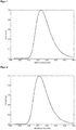
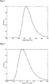
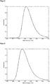
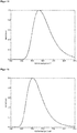
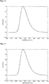
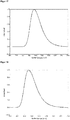
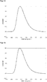
- One embodiment of the invention relates to organic molecules having an emission maximum at between 420 and 490 nm, more preferably between 430 and 470 nm, even more preferably between 440 and 460 nm.
- An embodiment of the invention relates to organic molecules which have an emission lifetime of at most 150 ⁇ s, in particular of at most 100 ⁇ s, of the highest 50 ⁇ s, or of at most 10 ⁇ s and / or a main emission band having a half-width of less than 120 nm, in particular less than 100 nm, smaller than 80 nm, or smaller than 60 nm and / or a photoluminescence quantum yield (PLQY) of greater than 30%, in particular greater than 35%, greater than 40%, greater than 45%, greater than 50%, or of greater than 60% and / or a ⁇ E (S 1 -T 1 ) value between the lowest excited singlet (S 1 ) and the underlying triplet (T 1 ) state of not higher than 5000 cm -1 , in particular not higher
- the molecules according to the invention have a "blue material index" (BMI), the quotient of the PLQY (in%) and their CIE y color coordinate of the light emitted by the molecule according to the invention of greater than 150, in particular greater than 200, greater than 250 or from more than 300 on.
- BMI blue material index
- the determination of the ⁇ E (S 1 -T 1 ) value can be carried out both by quantum mechanical calculations by means of computer programs known in the prior art be determined experimentally (eg by means of turbomole programs performing TD-DFT and CC2 calculations) or, as will be explained below.
- the energy difference ⁇ E (S 1 -T 1 ) can be described approximately quantum mechanically by the multiplied by the factor 2 so-called exchange integral.
- a graphical plot of the (logarithmic) intensity ratios In ⁇ Int (S 1 ⁇ S 0 ) / Int (T 1 ⁇ S 0 ) ⁇ measured at different temperatures against the inverse of the absolute temperature T generally yields a straight line.
- the measurement is carried out in a temperature range from room temperature (300 K) to 77 K or to 4.2 K, wherein the temperature is adjusted by means of a cryostat.
- the intensities are determined from the (corrected) spectra, where Int (S 1 ⁇ S 0 ) and Int (T 1 ⁇ S 0 ) represent the integrated fluorescence or phosphorescence band intensities which are determined by means of the programs belonging to the spectrophotometer to let.
- the respective transitions can be easily identified since the triplet band is at lower energy than the singlet band and gains in intensity with decreasing temperature.
- the measurements are carried out in oxygen-free diluted solutions (about 10 -2 mol / L) or on thin films of the corresponding molecules or on films doped with the corresponding molecules. If a solution is used as the sample, it is advisable to use a solvent or solvent mixture which forms glasses at low temperatures, such as 2-methyl-THF, THF (tetrahydrofuran) or aliphatic hydrocarbons. Used as a sample a film, so is the use of a matrix with a significantly larger singlet and triplet energy than that of the organic emitter molecules, z. B. PMMA (polymethylmethacrylate). This film can be applied from solution.
- the line slope is - ⁇ E / k B.
- An equivalent view shows that by measuring the temperature dependence of the emission decay time, the ⁇ E (S 1 -T 1 ) value can also be determined.
- a simple, approximate estimate of the ⁇ E (S 1 -T 1 ) value can also be made by reading the fluorescence and phosphorescence spectra at low temperature (eg 77 K or 4.2 K using a cryostat) be registered.
- the ⁇ E (S 1 -T 1 ) value then corresponds approximately to the energy difference between the high-energy rising edges of the fluorescence or phosphorescence band.
- the anode layer of the typical structure for example an ITO layer (indium tin oxide), is connected as the cathode.
- the organic component in particular an OLED, has a stacked construction.
- the individual OLEDs are arranged one above the other and not next to each other as usual.
- this design can be used in the generation of white light, the entire visible spectrum of which is typically imaged by the combination of the emitted light from blue, green and red emitters.
- a so-called charge generation layer is optionally inserted between two OLEDs.
- This consists of an n-doped and a p-doped layer, wherein the n-doped layer is typically applied closer to the anode.
- a so-called tandem OLED - occur two or more emission layers between the anode and cathode.
- three emission layers are arranged one above the other, wherein an emission layer emits red light, an emission layer emits green light, and an emission layer emits blue light, and optionally further charge generation, blocking or transport layers are applied between the individual emission layers.
- the respective emission layers are applied directly adjacent.
- a charge generation layer is in each case located between the emission layers.
- emission layers directly adjacent and separated by charge generation layers can be combined in an OLED.
- an encapsulation may be arranged above the electrodes and the organic layers.
- the encapsulation can be embodied, for example, in the form of a glass cover or in the form of a thin-layer encapsulation.
- the carrier material of the optoelectronic device may be, for example, glass, quartz, plastic, metal, a silicon wafer or any other suitable solid or flexible, optionally transparent material.
- the carrier material may comprise, for example, one or more materials in the form of a layer, a film, a plate or a laminate.
- transparent conductive metal oxides such as ITO (indium tin oxide), zinc oxide, tin oxide, cadmium oxide, titanium oxide, indium oxide or aluminum zinc oxide (AZO), Zn 2 SnO 4 , CdSnO 3 , ZnSnO 3 , MgIn 2 O 4 , GaInO 3 , Zn 2 In 2 O 5 or In 4 Sn 3 O 12 or mixtures of different transparent conductive oxides.
- PEDOT PSS (poly-3,4-ethylenedioxythiophene: polystyrenesulfonic acid), PEDOT (poly-3,4-ethylenedioxythiophene), m-MTDATA (4,4 ', 4 "-tris [phenyl (m) tolyl) amino] triphenylamine), spiro-TAD (2,2 ', 7,7'-tetrakis (N, N-diphenylamino) -9,9-spirobifluorene), DNTPD (4,4'-bis [N- [4 - ⁇ N, N-bis (3-methylphenyl) amino ⁇ phenyl] -N-phenylamino] biphenyl), NPB (N, N'-bis (1-naphthalenyl) -N, N'-bis-phenyl- (1,1'-biphenyl) -4,4'-diamine), NPNPB (N, N'-bis (1-naphthalenyl)
- small molecules may be used (eg copper phthalocyanine (CuPc eg 10 nm thick)) or metal oxides such as MoO 3 , V 2 O 5 for example.
- materials of an HTL tertiary amines, carbazole derivatives, polystyrenesulfonic acid-doped polyethylenedioxythiophene, camphorsulfonic acid-doped polyaniline poly-TPD (poly (4-butylphenyl-diphenyl-amine)), [alpha] -NPD (poly (4-butylphenyl-diphenyl-amine) )), TAPC (4,4'-cyclohexylidene bis [ N , N -bis (4-methylphenyl) benzenamine]), TCTA (tris (4-carbazoyl-9-ylphenyl) amine), 2-TNATA (4.4 ', 4 "-tris [2-naphthyl (phenyl) amino
- the HTL may comprise a p-doped layer comprising an inorganic or organic dopant in an organic hole-conducting matrix.
- inorganic dopant for example, transition metal oxides such as vanadium oxide, molybdenum oxide or tungsten oxide can be used.
- organic dopants for example, tetrafluorotetracyanoquinodimethane (F4-TCNQ), copper pentafluorobenzoate (Cu (I) pFBz) or transition metal complexes can be used.
- the layer thickness is 10 nm to 100 nm.
- an electron-blocking layer As materials of an electron-blocking layer it is possible to use, for example, mCP (1,3-bis (carbazol-9-yl) benzene), TCTA, 2-TNATA, mCBP (3,3-di (9H-carbazol-9-yl) biphenyl), tris Pcz (9,9'-diphenyl-6- (9-phenyl-9H-carbazol-3-yl) -9H, 9'H-3,3'-bicarbazole), CzSi (9- (4-tert-butylphenyl) 3,6-bis (triphenylsilyl) -9H-carbazole) or DCB (N, N'-dicarbazolyl-1,4-dimethylbenzene).
- mCP 1,3-bis (carbazol-9-yl) benzene
- TCTA 2,3-di (9H-carbazol-9-yl) biphenyl
- Pcz 9,9'-dipheny
- the emitter layer EML or emission layer consists of or comprises emitter material or a mixture comprising at least two emitter materials and optionally one or more host materials.
- Suitable host materials include mCP, TCTA, 2-TNATA, mCBP, CBP (4,4'-bis- (N-carbazolyl) -biphenyl), Sif87 (dibenzo [b, d] thiophen-2-yltriphenylsilane), Sif88 (Dibenzo [b, d] thiophen-2-yl) diphenylsilane) or DPEPO (bis [2 - ((oxo) diphenylphosphino) phenyl] ether).
- the common matrix materials such as CBP are suitable.
- the common matrix materials such as CBP are suitable.
- UHG matrix materials ultra-high energy gap materials
- the layer thickness is 10 nm to 250 nm.
- the layer thickness is 10 nm to 50 nm.
- the electron transport layer ETL can be, for example, materials based on AlQ 3 , TSPO 1, BPyTP 2 (2,7-di (2,2'-bipyridin-5-yl) triphenyl), Sif 87, Sif 88, BmPyPhB (1,3-bis [3, 5-di (pyridin-3-yl) phenyl] benzene) or BTB (4,4'-bis- [2- (4,6-diphenyl-1,3,5-triazinyl)] - 1,1'-biphenyl ) respectively.
- the layer thickness is 10 nm to 200 nm.
- a thin electron injection layer EIL for example, CsF, LiF, 8-hydroxyquinolinolatolithium (Liq), Li 2 O, BaF 2 , MgO or NaF can be used.
- the materials of the cathode layer may be metals or alloys, for example Al, Al> AlF, Ag, Pt, Au, Mg, Ag: Mg.
- Typical layer thicknesses are from 100 nm to 200 nm.
- one or more metals are used which are stable in air and / or which are self-passivating, for example by forming a thin protective oxide layer.
- the organic molecule according to the invention is used as the emission material in a light-emitting layer EML, wherein it is used either as a pure layer or in combination with one or more host materials.
- One embodiment of the invention relates to organic optoelectronic devices which have an external quantum efficiency (EQE) at 1000 cd / m 2 of greater than 5%, in particular greater than 8%, in particular greater than 10%, or greater than 13%, or greater than 16%.
- EQE external quantum efficiency
- n 1 to 4
- m 0 to 4
- R b is -Cl (1.3n + 1.3m equivalents), tris (Dibenzylideneacetone) dipalladium (0.01 equiv), 2- (dicyclohexylphosphino) -2 ', 4', 6' Triisopropylbiphenyl (0.04 equiv) and potassium phosphate tribasic (2.5n + 2.5m equivalents) are stirred under nitrogen in a toluene / water (10: 1) mixture for 12-24 hrs at 100 ° C. The crude product obtained is purified by flash chromatography or by recrystallization.
- R b -Br or R b -I instead of R b -Cl.
- the molecules according to the invention can each be obtained according to AAV2 or a combination of AAV3 and AAV4 or AAV3 and AAV5.
- the products of the synthetic routes differ in each case only by the yields obtained or purity before purification. After proper purification, the products are of equivalent quality.
- the BP86 functional Becke, AD Phys. Rev. A1988, 38, 3098-3100 ; Perdew, JP Phys. Rev. B1986, 33, 8822-8827 ), using the resolution of identity approximation (RI) ( Sierka, M .; Hogekamp, A .; Ahlrichs, RJ Chem. Phys. 2003, 118, 9136-9148 ; Becke, AD, J. Chem. Phys. 98 (1993) 5648-5652 ; Lee, C; Yang, W; Parr, RG Phys. Rev. B 37 (1988) 785-789 ) was used.
- RI identity approximation
- Excitation energies were determined for the BP86-optimized structure using the time-dependent DFT method (TD-DFT) using the B3LYP functional ( Becke, AD, J. Chem. Phys. 98 (1993) 5648-5652 ; Lee, C; Yang, W; Parr, RG Phys. Rev. B 37 (1988) 785-789 ; Vosko, SH; Wilk, L .; Nusair, M. Can. J. Phys. 58 (1980) 1200-1211 ; Stephens, PJ; Devlin, FJ; Chabalowski, CF; Fresh, MJJPhys.Chem. 98 (1994) 11623-11627 ).
- def2-SV (P) basis sets Weigend, F .; Ahlrichs, R. Phys. Chem. Chem. Phys. 2005, 7, 3297-3305 ; Rappoport, D .; Furrow, FJ Chem. Phys. 2010, 133, 134105 / 1-134105 / 11 ) and an m4 grid for numerical integration. All DFT calculations were done with the Turbomole program package (version 6.5) (TURBOMOLE V6.4 2012, a development of the University of Düsseldorf and Anlagens scholar Düsseldorf GmbH, 1989-2007, TURBOMOLE GmbH, since 2007, http://www.turbomole.com ) carried out.
- the sample concentration corresponded to 10mg / ml, given in toluene or chlorobenzene.
- the films were dried after coating for one minute at 70 ° C in air on a precision hot plate of LHG.
- Steady-state emission spectroscopy was performed with a Horiba Scientific FluoroMax-4 fluorescence spectrometer equipped with a 150 W xenon-arc lamp, excitation and emission monochromators and a Hamamatsu R928 photomultiplier tube, and a TCSPC option. Emission and excitation spectra were corrected by standard correction curves.
- Emission decay times were also measured on this system using the TCSPC method with the FM-2013 accessory and a TCSPC hub from Horiba Yvon Jobin.
- Excitation sources NanoLED 370 (wavelength: 371 nm, pulse duration: 1.1 ns), NanoLED 290 (wavelength: 294 nm, pulse duration: ⁇ 1 ns), SpectraLED 310 (wavelength: 314 nm), SpectraLED 355 (wavelength: 355 nm).
- the evaluation was carried out with the software package DataStation and the DAS 6 evaluation software.
- the photoluminescence quantum yield (PLQY) was measured by means of an Absolute PL Quantum Yield Measurement C9920-03G system from Hamamatsu Photonics. This consists of a 150 W xenon gas discharge lamp, automatically adjustable Czerny-Turner monochromators (250 nm to 950 nm) and an Ulbricht sphere with highly reflective spectral coating (a Teflon derivative), which is connected via a fiber optic cable with a PMA-12 multichannel detector with BT (back thinned) CCD chip with 1024 x 122 pixels (size 24 x 24 microns) is connected.
- PLQY photoluminescence quantum yield
- OLED devices can be created by means of vacuum sublimation technology. If a layer contains several components, the ratio of these is given in percentage by mass.
- OLEDs can be characterized by default; For this purpose, the electroluminescence spectra, the external quantum efficiency (measured in%) as a function of the brightness, calculated from the light detected by the photodiode, and the current are recorded.
- the lifetime of the OLEDs can be determined from the time course of the electroluminescence spectra.
- the specified LT50 value corresponds to the time at which the luminance has fallen to 50% of the starting value.
- the LT70 value corresponds to the time at which the luminance has fallen to 70% of the starting value.
- Example 1 was prepared according to AAV2 from 3-trifluoromethyl-9 H -carbazole and N -Mesityl-3-fluorophthalimide in a yield of 49%.
- 1 H NMR 500 MHz, chloroform-d
- ⁇ 8.40 m, 1H
- 7.63 (dd, J 8.8, 1.8 Hz, 1H)
- 7.28 - 7.24 m, 3H
- 6.95-6.92 m, 2H
- 2.27 s, 3H
- 2.11
- FIG. 1 shows the emission spectrum of Example 1 (10% in PMMA).
- the emission maximum is 469 nm.
- the photoluminescence quantum yield (PLQY) is 39% and the half width (FWHM) is 90 nm (0.49 eV).
- the result is a CIE y of 0.24 and a BMI of 163.
- the emission lifetime is 7.5 ⁇ s.
- Example 2 was prepared according to AAV2 from 3-trifluoromethyl-9 H- carbazole and N-methyl-3-fluorophthalimide in a yield of 67%.
- FIG. 2 shows the emission spectrum of Example 2 (10% in PMMA).
- the emission maximum is 458 nm.
- the photoluminescence quantum yield (PLQY) is 34% and the half width (FWHM) is 88 nm (0.50 eV).
- the result is a CIE y of 0.19 and a BMI of 179.
- the emission lifetime is 10.5 ⁇ s.
- Example 3 was prepared according to AAV2 from 2-trifluoromethyl-9 H- carbazole and N- mesityl-3-fluorophthalimide in a yield of 57%.
- 1 H NMR 500 MHz, chloroform-d
- FIG. 3 shows the emission spectrum of Example 3 (10% in PMMA).
- the emission maximum is 467 nm.
- the photoluminescence quantum yield (PLQY) is 46% and the half width (FWHM) is 86 nm (0.47 eV).
- the result is a CIE y of 0.22 and a BMI of 209.
- the emission lifetime is 8.5 ⁇ s.
- Example 4 was prepared according to AAV5 from 3- (3,6-Dibromcarbazolyl) - N produced -methylphthalimid and 2,4-trifluoromethylphenyl-1-boronic acid in a yield of 44%.
- 1 H NMR 500 MHz, chloroform-d
- 19 F NMR (471 MHz, CDCl3) ⁇ -57.00, -62.66.
- FIG. 4 shows the emission spectrum of Example 4 (10% in PMMA).
- the emission maximum is 465 nm.
- the photoluminescence quantum yield (PLQY) is 50% and the full width at half maximum (FWHM) is 89 nm (0.49 eV).
- the result is a CIE y of 0.21 and a BMI of 238.
- Example 5 was prepared according to AAV2 from 3-cyano-9 H -carbazole and N -Mesityl-3-fluorophthalimide in a yield of 62%.
- 1 H NMR 500 MHz, chloroform-d
- ⁇ 8.47-8.43 m, 1H
- 8.18-8.14 m, 2H
- 7.49 (ddd, J 8.4, 7.3, 1.2 Hz, 1H)
- 7.42-7.37 m, 1H
- 7.28-7.22 m , 2H
- 6.93 m, 2H), 2.27 (s, 3H), 2.10 (s, 3H), 2.07 (s, 3H).
- FIG. 5 shows the emission spectrum of Example 5 (10% in PMMA).
- the emission maximum is 462 nm.
- the photoluminescence quantum yield (PLQY) is 36% and the Half width (FWHM) 87 nm (0.49 eV).
- the result is a CIE y of 0.20 and a BMI of 180.
- the emission lifetime is 6.6 ⁇ s.
- Example 6 was prepared from 3- (3,6-Dibromcarbazolyl) by AAV 5 - prepared N -methylphthalimid and 2-cyanophenylboronic acid in a yield of 61%.
- 1 H NMR 500 MHz, chloroform-d
- FIG. 6 shows the emission spectrum of Example 6 (10% in PMMA).
- the emission maximum is 477 nm.
- the photoluminescence quantum yield (PLQY) is 56% and the half width (FWHM) is 93 nm (0.48 eV).
- the result is a CIE y of 0.30 and a BMI of 187.
- the emission lifetime is 59 ⁇ s.
- Example 7 was prepared from 3- (3,6-Dibromcarbazolyl) by AAV 5 - prepared N -mesitylphthalimid and pyrimidine-5-boronic acid in a yield of 22%.
- 1 H NMR 500 MHz, chloroform-d
- FIG. 7 shows the emission spectrum of Example 7 (10% in PMMA).
- the emission maximum is 490 nm.
- the photoluminescence quantum yield (PLQY) is 58% and the half width (FWHM) is 97 nm (0.48 eV).
- the result is a CIE y of 0.38 and a BMI of 153.
- the emission lifetime is 9.8 ⁇ s.
- Example 8 was prepared according to AAV 2 from N -mesityl-3-fluorophthalimide and 9H-pyrido [2,3-b] indoles in a yield of 26%.
- 1 H NMR 500 MHz, chloroform-d
- ⁇ 8.41-8.35 m, 2H
- 8.14-8.11 m, 1H
- 8.06-8.00 m, 2H
- 7.38 - 7.33 m, 2H
- 7.25 (dd, J 7.7, 4.9 Hz, 1H)
- 6.93 s, 1H
- 2.26 s, 3H
- 2.08 s, 3H
- FIG. 8 shows the emission spectrum of Example 8 (10% in PMMA).
- the emission maximum is 448 nm.
- the photoluminescence quantum yield (PLQY) is 32% and the half width (FWHM) is 86 nm (0.51 eV).
- the result is a CIE y of 0.15 and a BMI of 213.
- Example 9 was synthesized according to the following procedure: N- mesitylphthalimid (1 equivalent) and CuCN (1.5 equivalents) in dry DMF (2 mL per mmol of aryl bromide) 24 h at 150 ° C heated - in a Schlenk flask under nitrogen atmosphere, 3- (2-bromcarbazolyl). After cooling to room temperature, the The resulting brown precipitate was filtered off and washed with DMF. By adding twice the volume of water to the filtrate, the crude product was precipitated as a yellow-green solid. The precipitate was filtered off, washed with water and taken up in ethyl acetate. The resulting solution was dried over MgSO4 and the solvent was removed under reduced pressure.
- FIG. 9 shows the emission spectrum of Example 9 (10% in PMMA).
- the emission maximum is 463 nm.
- the photoluminescence quantum yield (PLQY) is 36% and the half-width (FWHM) 87 nm (0.48 eV).
- the result is a CIE y of 0.21 and a BMI of 171.
- Example 10 was prepared from 3- (3-Bromcarbazolyl) by AAV 5 - prepared N -methylphthalimid and 2,4-bis (trifluoromethyl) phenylboronic acid in a yield of 46%.
- 1 H NMR 500 MHz, chloroform-d
- 8.06-8.04 m, 1H
- FIG. 10 shows the emission spectrum of Example 10 (10% in PMMA).
- the emission maximum is 474 nm.
- the photoluminescence quantum yield (PLQY) is 61% and the half-width (FWHM) 92 nm. (0.49 eV).
- the result is a CIE y of 0.28 and a BMI of 218.
- the emission lifetime is 7.0 ⁇ s.
- Example 11 was prepared from 3- (1-Bromcarbazolyl) by AAV 5 - prepared N -mesitylphthalimid and 4-cyanophenylboronic acid in a yield of 22%.
- 1 H NMR 500 MHz, chloroform-d
- FIG. 11 shows the emission spectrum of Example 11 (10% in PMMA).
- the emission maximum is 482 nm.
- the photoluminescence quantum yield (PLQY) is 61% and the half width (FWHM) is 94 nm (0.48 eV).
- the result is a CIE y of 0.33 and a BMI of 185.
- Example 12 was prepared according to the following procedure: In a two-necked flask equipped with a reflux condenser under nitrogen atmosphere, 3- (1-Bromcarbazolyl) - N -mesitylphthalimid (1 equivalent) and CuCN (1.5 equivalents) in dry DMF for 15 h at 250 ° C heated. After cooling to RT, the crude product was precipitated from the reaction solution by adding the same volume of water. The precipitate was filtered off and treated with CH 2 Cl 2 . The resulting solution was washed with water, dried over MgSO4 and freed of solvent under reduced pressure. The residue was washed with hot ethanol. The washing solution was discarded and the residue recrystallized from toluene. Yield: 69%.
- FIG. 12 shows the emission spectrum of Example 12 (10% in PMMA).
- the emission maximum is 453 nm.
- the photoluminescence quantum yield (PLQY) is 44% and the full width at half maximum (FWHM) is 84 nm (0.49 eV).
- the result is a CIE y of 0.16 and a BMI of 275.
- Example 13 was prepared according to AAV 4 starting from 3- (3-Bromcarbazolyl) - N -methylphthalimid prepared in a yield of 57%.
- 1 H NMR 500 MHz, chloroform-d
- ⁇ 9.62-9.61 m, 1H
- 8.86-8.81 m, 4H
- 8.41-8.38 m, 1H
- FIG. 13 shows the emission spectrum of Example 13 (10% in PMMA).
- the emission maximum is 478 nm.
- the photoluminescence quantum yield (PLQY) is 58% and the half width (FWHM) is 92 nm. (0.48 eV).
- the result is a CIE y of 0.30 and a BMI of 193.
- Example 14 was prepared from 3- (1-Bromcarbazolyl) by AAV 5 - prepared N -mesitylphthalimid and 3,5-bis (trifluoromethyl) benzeneboronic acid in a yield of 49%.
- 1 H NMR 500 MHz, chloroform-d
- FIG. 14 shows the emission spectrum of Example 14 (10% in PMMA).
- the emission maximum is 477 nm.
- the photoluminescence quantum yield (PLQY) is 65% and the half-width (FWHM) 93 nm (0.48 eV).
- the result is a CIE y of 0.31 and a BMI of 210.
- FIG. 15 shows the emission spectrum of Example 15 (10% in PMMA).
- the emission maximum is 467 nm.
- the photoluminescence quantum yield (PLQY) is 48% and the half width (FWHM) is 92 nm (0.50 eV).
- the result is a CIE y of 0.24 and a BMI of 200.
- Example 16 was prepared by the conversion of 3- (3-Bromcarbazolyl) to AAV 4 - N- mesitylphthalimid made in the corresponding Boronic acid pinacol esters, and subsequent reaction with N -Mesityl-3-chlorophthalimide in a yield of 87%.
- FIG. 16 shows the emission spectrum of Example 16 (10% in PMMA).
- the emission maximum is 489 nm.
- the photoluminescence quantum yield (PLQY) is 59% and the half width (FWHM) is 97 nm (0.48 eV).
- the result is a CIE y of 0.39 and a BMI of 151.
- Example 17 was prepared according to AAV 4 by the conversion of 3- (3,6-Dibromcarbazolyl) - N- mesitylphthalimid in the corresponding bis (boronic acid pinacol ester) and the subsequent reaction with Chlordiphenyltriazin in a yield of 79% was prepared.
- FIG. 17 shows the emission spectrum of Example 17 (10% in PMMA).
- the emission maximum is 488 nm.
- the photoluminescence quantum yield (PLQY) is 55% and the full width at half maximum (FWHM) is 94 nm (0.47 eV).
- the result is a CIE y of 0.37 and a BMI of 149.
- Example 18 was prepared from 3- (4-Bromcarbazolyl) by AAV 5 - prepared N -mesitylphthalimid and 3,5-bis (trifluoromethyl) benzeneboronic acid in a yield of 63%.
- FIG. 18 shows the emission spectrum of Example 18 (10% in PMMA).
- the emission maximum is 480 nm.
- the photoluminescence quantum yield (PLQY) is 58% and the half-width (FWHM) is 92 nm (0.48 eV).
- the result is a CIE y of 0.31 and a BMI of 187.
- Example 19 was prepared from 3- (4-Bromcarbazolyl) by AAV 5 - prepared N -mesitylphthalimid and 4-cyanophenylboronic acid in a yield of 42%.
- FIG. 19 shows the emission spectrum of Example 19 (10% in PMMA).
- the emission maximum is 486 nm.
- the photoluminescence quantum yield (PLQY) is 56% and the full width at half maximum (FWHM) is 94 nm (0.47 eV).
- the result is a CIE y of 0.36 and a BMI of 156.
- Example 20 was prepared from 3- (3,6-Dibromcarbazolyl) by AAV 5 - prepared N -mesitylphthalimid and 2-trifluoromethylphenyl boronic acid in a yield of 40%.
- Example 20 (10% in PMMA) was measured. The emission maximum is 484 nm.
- the photoluminescence quantum yield (PLQY) is 68% and the full width at half maximum (FWHM) 94 nm (0.48 eV).
- the result is a CIE y of 0.35 and a BMI of 194.
- Example 21 was prepared according to AAV 4 starting from 3- (3-Bromcarbazolyl) - prepared (o -biphenyl) phthalimide in a yield of 66% - N.
- 1 H NMR 500 MHz, chloroform-d
- the product consists of two rotamers whose NMR signals are superimposed.
- FIG. 21 shows the emission spectrum of Example 21 (10% in PMMA).
- the emission maximum is 481 nm.
- the photoluminescence quantum yield (PLQY) is 68% and the half width (FWHM) is 92 nm (0.47 eV).
- the result is a CIE y of 0.33 and a BMI of 206.
- the emission lifetime is 5.7 ⁇ s.
- Example 22 was prepared according to AAV 4 starting from 3- (3-Bromcarbazolyl) - prepared in a yield of 42% (o -biphenyl) phthalimide - N.
- Example 22 (10% in PMMA) was recorded.
- the emission maximum is 489 nm.
- the photoluminescence quantum yield (PLQY) is 62% and the full width at half maximum (FWHM) 97 nm (0.48 eV).
- the result is a CIE y of 0.37 and a BMI of 168.
- the emission lifetime is 5.9 ⁇ s.
- Example 23 was 5 from 3- (3,6-Dibromcarbazolyl) of AAV - N - (o -biphenyl) phthalimide and 2-trifluoromethyl phenyl boronic acid in a yield of 80%.
- Example 23 The emission spectrum of Example 23 (10% in PMMA) was measured. The emission maximum is 483 nm. The photoluminescence quantum yield (PLQY) is 68% and the half width (FWHM) 93 nm (0.47 eV). The result is a CIE y of 0.34 and a BMI of 200.
- PLQY photoluminescence quantum yield
- FWHM half width
- Example 24 was prepared according to AAV 4 by the conversion of 3- (3-Bromcarbazolyl) - N - (o- biphenyl) phthalimide in the corresponding bis (boronic acid pinacol ester) and the subsequent reaction with 3-bromo-6-trifluoromethyl-benzonitrile in a yield made of 64%
- Example 24 (10% in PMMA) was measured. The emission maximum is 491 nm.
- the photoluminescence quantum yield (PLQY) is 65% and the half width (FWHM) is 96 nm (0.48 eV).
- the result is a CIE y of 0.37 and a BMI of 176.
- Example 25 was prepared according to AAV 4 by the conversion of 3- (2-Bromcarbazolyl) - prepared (o- biphenyl) phthalimide in the corresponding bis (boronic acid pinacol ester) and the subsequent reaction with 2-bromobenzonitrile in a yield of 97% - N.
- Example 25 (10% in PMMA) was recorded. The emission maximum is 476 nm.
- the photoluminescence quantum yield (PLQY) is 61% and the half width (FWHM) is 91 nm (0.48 eV).
- the result is a CIE y of 0.29 and a BMI of 210.
- Example 26 was prepared according to AAV 4 by the conversion of 3- (2-Bromcarbazolyl) - N - (o - (meta-terphenyl)) phthalimide in the corresponding bis (boronic acid pinacol ester) and the subsequent reaction produced with Chlordiphenyltriazin in a yield of 44% ,
- the emission spectrum of Example 26 (10% in PMMA) was recorded.
- the emission maximum is 486 nm.
- the photoluminescence quantum yield (PLQY) is 65% and the half-width (FWHM) 93 nm (0.47 eV).
- the result is a CIE y of 0.36 and a BMI of 181.
- the emission lifetime is 5.6 ⁇ s.
- Example 27 was prepared according to AAV 4 by the conversion of 3- (2-Bromcarbazolyl) - N - (o- biphenyl) phthalimide in the corresponding bis (boronic acid pinacol ester) and the subsequent reaction with 2-bromo-6-cyanopyridine in a yield of 13 % manufactured.
- the emission spectrum of Example 27 (10% in PMMA) was recorded. The emission maximum is 489 nm.
- the photoluminescence quantum yield (PLQY) is 61% and half width (FWHM) 97 nm (0.48 eV). The result is a CIE y of 0.38 and a BMI of 160.
- Example 28 was prepared according to AAV 4 by the conversion of 3- (3-Bromcarbazolyl) - N - (o- biphenyl) phthalimide in the corresponding bis (boronic acid pinacol ester) and the subsequent reaction with 4-bromo-3-trifluoromethyl-benzonitrile in a yield made of 94%.
- Example 28 (10% in PMMA) was measured. The emission maximum is 479 nm.
- the photoluminescence quantum yield (PLQY) is 63% and the half width (FWHM) is 92 nm (0.46 eV).
- the result is a CIE y of 0.31 and a BMI of 203.
- Example 29 was prepared according to AAV 4 by the conversion of 3- (3-Bromcarbazolyl) - N - (o- biphenyl) phthalimide in the corresponding bis (boronic acid pinacol ester) and subsequent reaction with 2-bromo-5-trifluoromethyl-benzonitrile in a yield of 36%.
- Example 29 The emission spectrum of Example 29 (10% in PMMA) was measured. The emission maximum is 475 nm.
- the photoluminescence quantum yield (PLQY) is 67% and the half width (FWHM) is 91 nm (0.48 eV).
- the result is a CIE y of 0.29 and a BMI of 231.
- Example 30 was prepared according to AAV 4 by the conversion of 3- (3-Bromcarbazolyl) - N- (o- biphenyl) phthalimide in the corresponding Boronic acid pinacol esters, and subsequent reaction with N - (o -biphenyl) phthalimide-3-chlorophthalimide in a yield made of 45%.
- Example 30 (10% in PMMA) was measured. The emission maximum is 490 nm.
- the photoluminescence quantum yield (PLQY) is 61% and the half width (FWHM) is 96 nm (0.48 eV).
- the result is a CIE y of 0.38 and a BMI of 161.
- Example 31 was prepared according to AAV 4 by the conversion of 3- (4-Bromcarbazolyl) - N - (o- biphenyl) phthalimide in the corresponding bis (boronic acid pinacol ester) and the subsequent reaction with 3-bromo-6-trifluoromethyl-benzonitrile in a yield made of 40%.
- Example 31 (10% in PMMA) was measured. The emission maximum is 474 nm.
- the photoluminescence quantum yield (PLQY) is 61% and the half-width (FWHM) 93 nm (0.48 eV).
- the result is a CIE y of 0.33 and a BMI of 203.
- Example 32 was prepared according to AAV 5 from 3- (2-Bromcarbazolyl) - N - (o -biphenyl) phthalimide and 3-cyanophenylboronic acid produced in a yield of 31%.
- Example 32 (10% in PMMA) was measured. The emission maximum is 474 nm.
- the photoluminescence quantum yield (PLQY) is 54% and the half width (FWHM) 93 nm (0.48 eV).
- the result is a CIE y of 0.32 and a BMI of 169.
- Example 3 and Example 5 were tested in OLEDs with the following structure: layer thickness D1 D2 10 100 nm al al 9 2 nm Liq Liq 8th 30 nm TPBi TPBi 7 10 nm DPEPO DPEPO 6 20 nm 3 : DPEPO 20:80 5 : DPEPO 30:70 5 10 nm CzSi CzSi 4 20 nm TCTA TCTA 3 50 nm NPB NPB 2 20 nm m-MTDATA m-MTDATA 1 120 nm ITO ITO ⁇ B> Performance data ⁇ / b> OLED component Maximum power efficiency (lm / W) Maximum Current Efficiency (cd / A) Maximum EQE (%) ⁇ max (nm) D1 12.8 ⁇ 0.6 26.0 ⁇ 0.5 12.7 ⁇ 0.3 476 D2 12.6 ⁇ 0.6 25.1 ⁇ 0.5 12.3 ⁇ 0.2 474
- Example 21 was tested in an OLED component ("component D3") with the following structure (proportion of the molecule according to the invention at the emission layer is given in mass percent): layer thickness material 9 100 nm al 8th 2 nm Liq 7 40 nm NBPhen 6 20 nm
- the emission maximum is 478 nm.
- Example 21 was tested in an OLED component ("component D4") having the following structure (proportion of the molecule according to the invention at the emission layer is given in percentage by mass): layer thickness material 7 100 nm al 6 2 nm Liq 5 40 nm NBPhen 4 20 nm
- component 21 (30%): mCBP 3 10 nm TCTA 2 80 nm NPB 1 130 nm ITO substratum Glass ⁇ B> Performance data ⁇ / b> EQE max (maximum external quantum efficiency) 8.91 ⁇ 0.03% EQE at 1000 cd / m 2 8.74 ⁇ 0.02% LT 80 at 1000 cd / m 2 72 h
- the emission maximum is 486 nm, CIEx was determined to be 0.24 and the CIEy: 0.39 at 4.5V.
Description
Die Erfindung betrifft rein organische Moleküle und deren Verwendung in organischen lichtemittierenden Dioden (OLEDs) und in anderen organischen optoelektronischen Vorrichtungen.The invention relates to purely organic molecules and their use in organic light emitting diodes (OLEDs) and in other organic optoelectronic devices.
Organische optoelektronische Vorrichtungen zeichnen sich dadurch aus, dass entweder elektrische Energie in Photonen umgewandelt wird (Organische Lichtemittierende Dioden, OLED oder Lichtemittierende Elektrochemische Zellen, LEEC) oder der umgekehrte Prozess abläuft (Organische Photovoltaik, OPV). Dabei ist es wichtig, dass diese Prozesse möglichst effizient ablaufen. Für den Bereich von OLEDs müssen daher idealerweise Materialien mit möglichst hoher photolumineszenter Quantenausbeute verwendet werden. Begrenzte Effizienzen von OLED-Materialien können durch Verwendung effizienter Materialien, die thermisch aktivierte verzögerte Fluoreszenz (TADF) zeigen, verbessert werden, da im Gegensatz zu rein fluoreszenten Materialien statt 25 % der in einer OLED gebildeten Exzitonen bis zu 100 % der Exzitonen genutzt werden können. Hierbei können auch die entstandenen Triplett-Excitonen in Singulett-Excitonen überführt werden, aus welchem Zustand dann Photonen emittiert werden können. Voraussetzung für eine solche thermische Rückbesetzung ist dabei ein geringer energetischer Abstand zwischen dem niedrigsten angeregten Singulett-(S1) und Triplett-Niveau (T1). Dies kann beispielweise durch Verwendung von Kupfer-(I)-Komplexen (siehe hierzu z. B.:
Die intensive Forschung in diesem Bereich zeigt, dass es weiterhin einen großen Bedarf an neuen Materialien gibt. So besteht zum Beispiel nach wie vor Bedarf an tiefblauen und himmelblauen TADF-OLEDs. Bestehende blaue TADF-Materialien zeigen oft hohe Exzitonenlebensdauern und/oder geringe Photolumineszenquantenzausbeuten, welche schlecht für effiziente und langlebige OLEDs sind. Als Maß für eine effiziente blaue OLED kann der Quotient aus der Stromeffizienz in cd/A und dem y-Wert der CIE-Farbkoordinate (CIEy) des von der OLED emittierten Lichts verwendet werden, also eine auf den CIEy-Wert normierte Effizienz. Neben den erwähnten Eigenschaften der Materialien ist für eine Kommerzialisierung ebenso die Zugänglichkeit relevant. Dies schließt die Verfügbarkeit von Synthesebausteinen, als auch den Aufwand für die eigentliche Synthese des funktionellen Materials, insbesondere dessen Aufreinigung mit ein.The intensive research in this area shows that there is still a great need for new materials. For example, there is still a need for deep blue and sky blue TADF OLEDs. Existing blue TADF materials often show high excitonic lifetimes and / or low photoluminescent quantum yields, which are poor for efficient and long-lived OLEDs. As a measure of an efficient blue OLED, the quotient of the current efficiency in cd / A and the y value of the CIE color coordinate (CIE y ) of the light emitted by the OLED can be used, ie an efficiency normalized to the CIE y value. Besides the mentioned properties of the materials, accessibility is also relevant for commercialization. This excludes the availability of building blocks, as well as the effort for the actual synthesis of the functional material, in particular its purification with a.
Der vorliegenden Erfindung lag die Aufgabe zu Grunde, Moleküle bereitzustellen, die sich zur Verwendung als Emittermaterialien in OLEDs eignen, die blaues Licht emittieren.The object of the present invention was to provide molecules that are suitable for use as emitter materials in OLEDs that emit blue light.
Überraschenderweise wurde festgestellt, dass durch Verwendung geeigneter Donoreinheiten in Kombination mit Phthalimid-Akzeptoreinheiten Moleküle mit Emissionsmaxima bei Wellenlängen unterhalb von 491 nm erhalten werden können, welche hohe Quantenausbeuten und geringe Exzitonenlebensdauern aufweisen. Da die Effizienz des Bauteils nach Optimierung des Stack-Designs typischerweise direkt mit der Photolumineszenquantenzausbeute (PLQY) des Emittermaterials korreliert, wurde für die erfindungsgemäßen Moleküle ein technischer Index analog zu dem oben beschriebenen bekannten Effizienzindex für blaue OLEDs ermittelt. Dieser Blaumaterialindex ("blue material index", BMI) ergibt sich als Quotient aus der PLQY (in %) und der CIEy-Farbkoordinate des von dem erfindungsgemäßen Molekül emittierten Lichts.Surprisingly, it has been found that by using suitable donor units in combination with phthalimide acceptor units, molecules with emission maxima at wavelengths below 491 nm can be obtained, which have high quantum yields and low exciton lifetimes. Since the component's efficiency typically correlates directly with the photoluminescence quantum yield (PLQY) of the emitter material after optimization of the stack design, a technical index analogous to the above-described known efficiency index for blue OLEDs was determined for the molecules according to the invention. This blue material index (BMI) is calculated as the quotient of the PLQY (in%) and the CIE y color coordinate of the light emitted by the molecule according to the invention.
Die erfindungsgemäßen organischen Moleküle weisen eine Struktur der Formel A1 auf oder bestehen aus einer Struktur der Formel A1.

- A ist bei jedem Auftreten gleich oder verschieden CRb oder N;
- RN ist ausgewählt aus der Gruppe bestehend aus Methyl, Phenyl, Xylyl, Mesityl, Naphtyl, Biphenyl, Naphthylphenyl, Terphenyl und 2,4,6-Triphenylphenyl.
- A is the same or different CR b or N at each occurrence;
- R N is selected from the group consisting of methyl, phenyl, xylyl, mesityl, naphthyl, biphenyl, naphthylphenyl, terphenyl and 2,4,6-triphenylphenyl.
Ra ist bei jedem Auftreten unabhängig voneinander ausgewählt aus der Gruppe bestehend aus H, Deuterium, einer Alkylgruppe und einer Arylgruppe;
Rb ist bei jedem Auftreten gleich oder verschieden H, Deuterium, CF3, C(=O)R1, CN, eine unsubstituierte oder mit einem oder mehreren R2 substituierte Alkylgruppe, eine unsubstituierte oder mit einem oder mehreren R2 substituierte Arylgruppe, die optional mit einer oder mehreren unsubstituierten Alkylgruppe und/oder mit einer oder mehreren unsubstituierten oder Alkyl-substituierten Arylgruppe substituiert ist, eine unsubstituierte oder mit einem oder mehreren R2 und/ oder mit einer oder mehreren unsubstituierten Alkylgruppe und/oder mit einer oder mehreren unsubstituierten oder Alkyl-substituierten Arylgruppe substituierte Heteroarylgruppe, eine Gruppe der Unterformel T1 oder eine Gruppe der Unterformel T2:

RN2 ist eine Alkylgruppe, eine unsubstituierte oder mit einem oder mehreren RN3 substituierte Arylgruppe oder eine unsubstituierte oder mit einem oder mehreren RN3 substituierte Heteroarylgruppe.
RN3 ist eine Alkylgruppe, eine Arylgruppe oder eine Heteroarylgruppe.
R1 ist bei jedem Auftreten eine unsubstituierte oder mit einem oder mehreren R2 substituierte Arylgruppe.
R2 ist bei jedem Auftreten gleich oder verschieden F, CF3 oder CN;
wobei mindestens ein und maximal vier A gleich N ist oder mindestens ein Rb ausgewählt ist aus der Gruppe bestehend aus, CF3, C(=O)R1, CN, einer mit einem oder mehreren R2 substituierten Alkylgruppe, einer mit einem oder mehreren R2 substituierten Arylgruppe, die optional mit einer oder mehreren unsubstituierten Alkylgruppe und/oder mit einer oder mehreren unsubstituierten oder Alkyl-substituierten Arylgruppe substituiert ist, einer unsubstituierten oder mit einem oder mehreren R2 und/ oder mit einer oder mehreren unsubstituierten Alkylgruppe und/oder mit einer oder mehreren unsubstituierten oder Alkyl-substituierten Arylgruppe substituierten Heteroarylgruppe und einer Gruppe der Unterformel T1 oder eine Gruppe der Unterformel T2:

RN2 ist eine Alkylgruppe, eine unsubstituierte oder mit einem oder mehreren RN3 substituierte Arylgruppe oder eine unsubstituierte oder mit einem oder mehreren RN3 substituierte Heteroarylgruppe.
RN3 ist eine Alkylgruppe, eine Arylgruppe oder Heteroarylgruppe.R a in each occurrence is independently selected from the group consisting of H, deuterium, an alkyl group and an aryl group;
R b is the same or different H, Deuterium, CF 3 , C (= O) R 1 , CN, an unsubstituted or substituted with one or more R 2 alkyl group, an unsubstituted or substituted with one or more R 2 aryl group, which is optionally substituted with one or more unsubstituted alkyl group and / or with one or more unsubstituted or alkyl-substituted aryl group, an unsubstituted or with one or more R 2 and / or with one or more unsubstituted alkyl group and / or with one or more unsubstituted or alkyl-substituted aryl group substituted heteroaryl group, a group of sub-formula T1 or a group of sub-formula T2:
R N2 is an alkyl group, an unsubstituted or substituted by one or more R N3 aryl group or an unsubstituted or substituted with one or more R N3 heteroaryl group.
R N3 is an alkyl group, an aryl group or a heteroaryl group.
R 1 is an unsubstituted or substituted with one or more R 2 aryl group at each occurrence.
R 2 is the same or different at each occurrence, F, CF 3 or CN;
wherein at least one and at most four A is N or at least one R b is selected from the group consisting of CF 3 , C (= O) R 1 , CN, a substituted with one or more R 2 alkyl group, one with one or a plurality of R 2 -substituted aryl groups which is optionally substituted by one or more unsubstituted alkyl groups and / or by one or more unsubstituted or alkyl-substituted aryl groups, an unsubstituted or one or more R 2 and / or one or more unsubstituted alkyl groups and / or with one or more unsubstituted or alkyl-substituted Aryl group substituted heteroaryl group and a group of sub-formula T1 or a group of sub-formula T2:
R N2 is an alkyl group, an unsubstituted or substituted by one or more R N3 aryl group or an unsubstituted or substituted with one or more R N3 heteroaryl group.
R N3 is an alkyl group, an aryl group or a heteroaryl group.
In einer Ausführungsform ist mindestens ein und maximal vier A gleich N oder mindestens ein Rb ist ausgewählt aus der Gruppe bestehend aus CF3, C(=O)R1, CN, einer mit einem oder mehreren R2 substituierten Alkylgruppe, einer unsubstituierten oder mit einem oder mehreren R2 substituierten 6-Ring-Arylgruppe, die optional mit einer oder mehreren unsubstituierten Alkylgruppe und/oder mit einer oder mehreren unsubstituierten oder Alkyl-substituierten Arylgruppe substituiert ist, einer unsubstituierten oder mit einem oder mehreren R2 und/oder mit einer oder mehreren unsubstituierten Alkylgruppe und/oder mit einer oder mehreren unsubstituierten oder Alkyl-substituierten Arylgruppe substituierten 6-Ring-Heteroarylgruppe und einer Gruppe der Unterformel T1 oder eine Gruppe der Unterformel T2:

RN2 ist eine Alkylgruppe, eine unsubstituierte oder mit einem oder mehreren RN3 substituierte Arylgruppe oder eine unsubstituierte oder mit einem oder mehreren RN3 substituierte Heteroarylgruppe.
RN3 ist eine Alkylgruppe, eine Arylgruppe oder eine Heteroarylgruppe.In one embodiment, at least one and at most four A is N or at least one R b is selected from the group consisting of CF 3 , C (= O) R 1 , CN, an alkyl group substituted with one or more R 2 , an unsubstituted or substituted with one or more R 2 substituted 6-membered aryl group, which is optionally substituted with one or more unsubstituted alkyl group and / or with one or more unsubstituted or alkyl-substituted aryl group, an unsubstituted or with one or more R 2 and / or with one or more unsubstituted alkyl group and / or 6-ring heteroaryl group substituted by one or more unsubstituted or alkyl-substituted aryl groups and a group of sub-formula T1 or a group of sub-formula T2:
R N2 is an alkyl group, an unsubstituted or substituted by one or more R N3 aryl group or an unsubstituted or substituted with one or more R N3 heteroaryl group.
R N3 is an alkyl group, an aryl group or a heteroaryl group.
In einer Ausführungsform ist Rb wie oben definiert mit der Maßgabe, dass Rb nicht gleich Pyridin oder Pyrimidin ist.
In einer Ausführungsform weist das organische Molekül eine Struktur der Formel A2 auf oder hat eine Struktur der Formel A2.

- RN ist Methyl, Phenyl, Xylyl, Mesityl, Naphtyl, Biphenyl, Naphthylphenyl, Terphenyl oder 2,4,6-Triphenylphenyl;
- Ra ist bei jedem Auftreten gleich oder verschieden H, Deuterium, eine Alkylgruppe oder eine Arylgruppe;
- Rc ist bei jedem Auftreten gleich oder verschieden CF3, C(=O)R1, CN, eine mit einem oder mehreren R2 substituierte Alkylgruppe, eine substituierte Arylgruppe, die optional mit einer oder mehreren unsubstituierten Alkylgruppe und/oder mit einer oder mehreren unsubstituierten oder Alkyl-substituierten Arylgruppe substituiert ist, eine unsubstituierte oder mit einem oder mehreren R2 und/ oder mit einer oder mehreren unsubstituierten Alkylgruppe und/oder mit einer oder mehreren unsubstituierten oder Alkyl-substituierten Arylgruppe substituierte Heteroarylgruppe oder eine Gruppe der Unterformel T1 oder eine Gruppe der Unterformel T2:

RN2 ist eine Alkylgruppe, eine unsubstituierte oder mit einem oder mehreren RN3 substituierte Arylgruppe oder eine unsubstituierte oder mit einem oder mehreren RN3 substituierte Heteroarylgruppe.
In one embodiment, the organic molecule has a structure of the formula A2 or has a structure of the formula A2.
- R N is methyl, phenyl, xylyl, mesityl, naphthyl, biphenyl, naphthylphenyl, terphenyl or 2,4,6-triphenylphenyl;
- R a is the same or different H, deuterium, an alkyl group or an aryl group at each occurrence;
- R c is the same or different CF 3 , C (= O) R 1 , CN, an alkyl group substituted by one or more R 2 , a substituted aryl group optionally containing one or more unsubstituted alkyl groups and / or one or more substituents substituted unsubstituted or alkyl-substituted aryl group, an unsubstituted or substituted with one or more R 2 and / or with one or more unsubstituted alkyl group and / or with one or more unsubstituted or alkyl-substituted aryl group heteroaryl or a group of the sub-formula T1 or a group of sub-formula T2:
R N2 is an alkyl group, an unsubstituted or substituted by one or more R N3 aryl group or an unsubstituted or substituted with one or more R N3 heteroaryl group.
RN3 ist eine Alkylgruppe, eine Arylgruppe oder eine Heteroarylgruppe.
Rd ist bei jedem Auftreten gleich oder verschieden H, Deuterium, CF3, C(=O)R1, CN, eine unsubstituierte oder mit einem oder mehreren R2 substituierte Alkylgruppe, eine unsubstituierte oder mit einem oder mehreren R2 und/oder mit einer oder mehreren unsubstituierten Alkylgruppe und/ oder mit einer oder mehreren unsubstituierten oder Alkyl-substituierten Arylgruppe substituierte Arylgruppe oder eine unsubstituierte oder mit einem oder mehreren R2 und/oder mit einer oder mehreren unsubstituierten Alkylgruppe und/ oder mit einer oder mehreren unsubstituierten oder Alkyl-substituierten Arylgruppe substituierte Heteroarylgruppe oder eine Gruppe der Unterformel T1 oder eine Gruppe der Unterformel T2:

RN2 ist eine Alkylgruppe, eine unsubstituierte oder mit einem oder mehreren RN3 substituierte Arylgruppe oder eine unsubstituierte oder mit einem oder mehreren RN3 substituierte Heteroarylgruppe.
RN3 ist eine Alkylgruppe, eine Arylgruppe oder eine Heteroarylgruppe.R N3 is an alkyl group, an aryl group or a heteroaryl group.
R d is the same or different H, Deuterium, CF 3 , C (= O) R 1 , CN, an unsubstituted or substituted with one or more R 2 alkyl group, an unsubstituted or with one or more R 2 and / or Aryl group substituted with one or more unsubstituted alkyl group and / or with one or more unsubstituted or alkyl-substituted aryl group or an unsubstituted or with one or more R 2 and / or with one or more unsubstituted alkyl group and / or with one or more unsubstituted or alkyl -substituted aryl group-substituted heteroaryl group or a group of sub-formula T1 or a group of sub-formula T2:
R N2 is an alkyl group, an unsubstituted or substituted by one or more R N3 aryl group or an unsubstituted or substituted with one or more R N3 heteroaryl group.
R N3 is an alkyl group, an aryl group or a heteroaryl group.
In einer weiteren Ausführungsform ist Rc bei jedem Auftreten unabhängig voneinander ausgewählt aus der Gruppe bestehend aus CF3, C(=O)R1, CN, einer mit einem oder mehreren R2 substituierten Alkylgruppe, einer mit einem oder mehreren R2 substituierten 6-Ring-Arylgruppe, die optional mit einer oder mehreren unsubstituierten Alkylgruppe und/oder mit einer oder mehreren unsubstituierten oder Alkyl-substituierten Arylgruppe substituiert ist, einer unsubstituierten oder mit einem oder mehreren R2 und/oder mit einer oder mehreren unsubstituierten Alkylgruppe und/ oder mit einer oder mehreren unsubstituierten oder Alkyl-substituierten Arylgruppe substituierten 6-Ring-Heteroarylgruppe und einer Gruppe der Unterformel T1 oder einer Gruppe der Unterformel T2:

RN2 ist eine Alkylgruppe, eine unsubstituierte oder mit einem oder mehreren RN3 substituierte Arylgruppe oder eine unsubstituierte oder mit einem oder mehreren RN3 substituierte Heteroarylgruppe.
RN3 ist eine Alkylgruppe, eine Arylgruppe oder eine Heteroarylgruppe.In a further embodiment, R c is independently at each occurrence selected from the group consisting of CF 3, C (= O) R 1, CN, one with one or more R 2 substituted alkyl group, with one or more R 2 substituted 6 Ring aryl group optionally substituted with one or more unsubstituted alkyl group and / or one or more unsubstituted or alkyl substituted aryl group, an unsubstituted or with one or more R 2 and / or with one or more unsubstituted alkyl group and / or 6-membered heteroaryl group substituted with one or more unsubstituted or alkyl-substituted aryl groups and a group of sub-formula T1 or a group of sub-formula T2:
R N2 is an alkyl group, an unsubstituted or substituted by one or more R N3 aryl group or an unsubstituted or substituted with one or more R N3 heteroaryl group.
R N3 is an alkyl group, an aryl group or a heteroaryl group.
In einer weiteren Ausführungsform ist Rc wie oben definiert mit der Maßgabe, dass Rc nicht gleich Pyridin oder Pyrimidin ist.In another embodiment, R c is as defined above with the proviso that R c is not the same as pyridine or pyrimidine.
In einer weiteren Ausführungsform ist Rd bei jedem Auftreten gleich H.In another embodiment, R d is H. at each occurrence.
In einer Ausführungsform weist das organische Molekül eine Struktur der Formel A3 auf oder hat eine Struktur der Formel A3.

- RN ist Methyl, Phenyl, Xylyl, Mesityl, Naphtyl, Biphenyl, Naphthylphenyl, Terphenyl oder 2,4,6-Triphenylphenyl;
- Ra ist bei jedem Auftreten gleich oder verschieden H, Deuterium, eine Alkylgruppe oder eine Arylgruppe;
- Rc ist bei jedem Auftreten unabhängig voneinander ausgewählt aus der Gruppe bestehend aus CF3, C(=O)R1, CN, einer mit einem oder mehreren R2 substituierten Alkylgruppe, einer substituierten Arylgruppe, die optional mit einer oder mehreren unsubstituierten Alkylgruppe und/oder mit einer oder mehreren unsubstituierten oder Alkyl-substituierten Arylgruppe substituiert ist, einer unsubstituierten oder mit einem oder mehreren R2 und/oder mit einer oder mehreren unsubstituierten Alkylgruppe und/oder mit einer oder mehreren unsubstituierten oder Alkyl-substituierten Arylgruppe substituierten Heteroarylgruppe und einer Gruppe der Unterformel T1 oder einer Gruppe der Unterformel T2:

RN2 ist eine Alkylgruppe, eine unsubstituierte oder mit einem oder mehreren RN3 substituierte Arylgruppe oder eine unsubstituierte oder mit einem oder mehreren RN3 substituierte Heteroarylgruppe.
- R N is methyl, phenyl, xylyl, mesityl, naphthyl, biphenyl, naphthylphenyl, terphenyl or 2,4,6-triphenylphenyl;
- R a is the same or different H, deuterium, an alkyl group or an aryl group at each occurrence;
- R c at each occurrence is independently selected from the group consisting of CF 3 , C (= O) R 1 , CN, an alkyl group substituted with one or more R 2 , a substituted aryl group optionally containing one or more unsubstituted alkyl groups and or is substituted by one or more unsubstituted or alkyl-substituted aryl group, an unsubstituted or with one or more R 2 and / or with one or more unsubstituted alkyl group and / or with one or more unsubstituted or alkyl-substituted aryl group-substituted heteroaryl group and a group of sub-formula T1 or a group of sub-formula T2:
R N2 is an alkyl group, an unsubstituted or substituted by one or more R N3 aryl group or an unsubstituted or substituted with one or more R N3 heteroaryl group.
Rd ist bei jedem Auftreten gleich oder verschieden unabhängig voneinander ausgewählt aus der Gruppe bestehend aus H, Deuterium, CF3, C(=O)R1, CN, einer unsubstituierten oder mit einem oder mehreren R2 substituierten Alkylgruppe, einer unsubstituierten oder mit einem oder mehreren R2 und/oder mit einer oder mehreren unsubstituierten Alkylgruppe und/oder mit einer oder mehreren unsubstituierten oder Alkyl-substituierten Arylgruppe substituierten Arylgruppe, einer unsubstituierten oder mit R2 und/oder mit einer oder mehreren unsubstituierten Alkylgruppe und/ oder mit einer oder mehreren unsubstituierten oder Alkyl-substituierten Arylgruppe substituierten Heteroarylgruppe und einer Gruppe der Unterformel T1 oder einer Gruppe der Unterformel T2:

RN2 ist eine Alkylgruppe, eine unsubstituierte oder mit einem oder mehreren RN3 substituierte Arylgruppe oder eine unsubstituierte oder mit einem oder mehreren RN3 substituierte Heteroarylgruppe.
RN3 ist eine Alkylgruppe, eine Arylgruppe oder eine Heteroarylgruppe.R d is the same or different independently selected from the group consisting of H, deuterium, CF 3 , C (= O) R 1 , CN, an unsubstituted or substituted with one or more R 2 alkyl group, an unsubstituted or with each occurrence one or more R 2 and / or with one or more unsubstituted alkyl group and / or with one or more unsubstituted or alkyl-substituted aryl group substituted aryl group, an unsubstituted or with R 2 and / or with one or more unsubstituted alkyl group and / or with a or a plurality of unsubstituted or alkyl-substituted aryl group-substituted heteroaryl group and a group of sub-formula T1 or a group of sub-formula T2:
R N2 is an alkyl group, an unsubstituted or substituted by one or more R N3 aryl group or an unsubstituted or substituted with one or more R N3 heteroaryl group.
R N3 is an alkyl group, an aryl group or a heteroaryl group.
In einer weiteren Ausführungsform ist Rc bei jedem Auftreten unabhängig voneinander ausgewählt aus der Gruppe bestehend aus CF3, C(=O)R1, CN, einer mit einem oder mehreren R2 substituierten Alkylgruppe, einer mit einem oder mehreren R2 substituierten 6-Ring-Arylgruppe, die optional mit einer oder mehreren unsubstituierten Alkylgruppe und/oder mit einer oder mehreren unsubstituierten oder Alkyl-substituierten Arylgruppe substituiert ist, einer unsubstituierten oder mit einem oder mehreren R2 und/oder mit einer oder mehreren unsubstituierten Alkylgruppe und/ oder mit einer oder mehreren unsubstituierten oder Alkyl-substituierten Arylgruppe substituierten 6-Ring-Heteroarylgruppe und einer Gruppe der Unterformel T1 oder einer Gruppe der Unterformel T2:

RN2 ist eine Alkylgruppe, eine unsubstituierte oder mit einem oder mehreren RN3 substituierte Arylgruppe oder eine unsubstituierte oder mit einem oder mehreren RN3 substituierte Heteroarylgruppe.
RN3 ist eine Alkylgruppe, eine Arylgruppe oder eine Heteroarylgruppe.In a further embodiment, R c is independently at each occurrence selected from the group consisting of CF 3, C (= O) R 1, CN, one with one or more R 2 substituted alkyl group, with one or more R 2 substituted 6 Ring aryl group optionally substituted with one or more unsubstituted alkyl group and / or one or more unsubstituted or alkyl substituted aryl group, an unsubstituted or with one or more R 2 and / or with one or more unsubstituted alkyl group and / or 6-membered heteroaryl group substituted with one or more unsubstituted or alkyl-substituted aryl groups and a group of sub-formula T1 or a group of sub-formula T2:
R N2 is an alkyl group, an unsubstituted or substituted by one or more R N3 aryl group or an unsubstituted or substituted with one or more R N3 heteroaryl group.
R N3 is an alkyl group, an aryl group or a heteroaryl group.
In einer weiteren Ausführungsform ist Rc wie oben definiert mit der Maßgabe, dass Rc nicht gleich Pyridin oder Pyrimidin ist.In another embodiment, R c is as defined above with the proviso that R c is not the same as pyridine or pyrimidine.
In einer weiteren Ausführungsform ist Rd bei jedem Auftreten gleich H.In another embodiment, R d is H. at each occurrence.
In einer weiteren Ausführungsform weist das organische Molekül eine Struktur der Formel A4 auf oder hat eine Struktur der Formel A4

- RN ist Methyl, Phenyl, Xylyl, Mesityl, Naphtyl, Biphenyl, Naphthylphenyl, Terphenyl oder 2,4,6-Triphenylphenyl;
- Ra ist bei jedem Auftreten gleich oder verschieden H, Deuterium, eine Alkylgruppe oder eine Arylgruppe;
- Rc ist bei jedem Auftreten unabhängig voneinander ausgewählt aus der Gruppe bestehend aus CF3, C(=O)R1, CN, einer mit einem oder mehreren R2 substituierten Alkylgruppe, einer mit einem oder mehreren R2 substituierten Arylgruppe, die optional mit einer oder mehreren unsubstituierten Alkylgruppe und/oder mit einer oder mehreren unsubstituierten oder Alkyl-substituierten Arylgruppe substituiert ist, einer unsubstituierten oder mit einem oder mehreren R2 und/oder mit einer oder mehreren unsubstituierten Alkylgruppe und/oder mit einer oder mehreren unsubstituierten oder Alkyl-substituierten Arylgruppe substituierten Heteroarylgruppe und einer Gruppe der Unterformel T1 oder einer Gruppe der Unterformel T2:

- Rd ist bei jedem Auftreten gleich oder verschieden unabhängig voneinander ausgewählt aus der Gruppe H, Deuterium, CF3, C(=O)R1, CN, einer unsubstituierten oder mit einem oder mehreren R2 substituierten Alkylgruppe, einer unsubstituierten oder mit einem oder mehreren R2 und/oder mit einer oder mehreren unsubstituierten Alkylgruppe und/oder mit einer oder mehreren unsubstituierten oder Alkyl-substituierten Arylgruppe substituierten Arylgruppe, einer unsubstituierten oder mit R2 und/oder mit einer oder mehreren unsubstituierten Alkylgruppe und/oder mit einer oder mehreren unsubstituierten oder Alkyl-substituierten Arylgruppe substituierten Heteroarylgruppe und einer Gruppe der Unterformel T1 oder einer Gruppe der Unterformel T2:

RN2 ist eine Alkylgruppe, eine unsubstituierte oder mit einem oder mehreren RN3 substituierte Arylgruppe oder eine unsubstituierte oder mit einem oder mehreren RN3 substituierte Heteroarylgruppe.
- R N is methyl, phenyl, xylyl, mesityl, naphthyl, biphenyl, naphthylphenyl, terphenyl or 2,4,6-triphenylphenyl;
- R a is the same or different H, deuterium, an alkyl group or an aryl group at each occurrence;
- R c in each occurrence is independently selected from the group consisting of CF 3 , C (= O) R 1 , CN, an alkyl group substituted by one or more R 2 , an aryl group substituted by one or more R 2 , optionally substituted with one or more unsubstituted alkyl group and / or with one or more unsubstituted or alkyl-substituted aryl group, an unsubstituted or with one or more R 2 and / or with one or more unsubstituted alkyl group and / or with one or more unsubstituted or alkyl substituted aryl group substituted heteroaryl group and a group of sub-formula T1 or a group of sub-formula T2:
- R d is the same or different independently of each other selected from the group H, deuterium, CF 3 , C (= O) R 1 , CN, an unsubstituted or substituted with one or more R 2 alkyl group, an unsubstituted or one or a plurality of R 2 and / or with one or more unsubstituted alkyl group and / or with one or more unsubstituted or alkyl-substituted aryl group substituted aryl group, an unsubstituted or with R 2 and / or with one or more unsubstituted alkyl group and / or with one or more unsubstituted or alkyl-substituted aryl group-substituted heteroaryl group and a group of sub-formula T1 or a group of sub-formula T2:
R N2 is an alkyl group, an unsubstituted or substituted by one or more R N3 aryl group or an unsubstituted or substituted with one or more R N3 heteroaryl group.
In einer weiteren Ausführungsform ist Rc bei jedem Auftreten unabhängig voneinander ausgewählt aus der Gruppe bestehend aus CF3, C(=O)R1, CN, einer mit einem oder mehreren R2 substituierten Alkylgruppe, einer mit einem oder mehreren R2 substituierten 6-Ring-Arylgruppe, die optional mit einer oder mehreren unsubstituierten Alkylgruppe und/oder mit einer oder mehreren unsubstituierten oder Alkyl-substituierten Arylgruppe substituiert ist, einer unsubstituierten oder mit einem oder mehreren R2 und/oder mit einer oder mehreren unsubstituierten Alkylgruppe und/oder mit einer oder mehreren unsubstituierten oder Alkyl-substituierten Arylgruppe substituierten 6-Ring-Heteroarylgruppe und einer Gruppe der Unterformel T1 oder einer Gruppe der Unterformel T2:

RN3 ist eine Alkylgruppe, eine Arylgruppe oder eine Heteroarylgruppe.In a further embodiment, R c is independently at each occurrence selected from the group consisting of CF 3, C (= O) R 1, CN, one with one or more R 2 substituted alkyl group, with one or more R 2 substituted 6 Ring aryl group optionally substituted with one or more unsubstituted alkyl group and / or one or more unsubstituted or alkyl substituted aryl group, an unsubstituted or with one or more R 2 and / or with one or more unsubstituted alkyl group and / or 6-membered heteroaryl group substituted with one or more unsubstituted or alkyl-substituted aryl groups and a group of sub-formula T1 or a group of sub-formula T2:
R N3 is an alkyl group, an aryl group or a heteroaryl group.
In einer weiteren Ausführungsform ist Rc wie oben definiert mit der Maßgabe, dass Rc nicht gleich Pyridin oder Pyrimidin ist.In another embodiment, R c is as defined above with the proviso that R c is not the same as pyridine or pyrimidine.
In einer weiteren Ausführungsform ist Rd bei jedem Auftreten gleich H.In another embodiment, R d is H. at each occurrence.
In einer weiteren Ausführungsform weist das organische Molekül eine Struktur der Formel A5 auf oder hat eine Struktur der Formel A5.

- RN ist Methyl, Phenyl, Xylyl, Mesityl, Naphtyl, Biphenyl, Naphthylphenyl, Terphenyl oder 2,4,6-Triphenylphenyl;
- Ra ist bei jedem Auftreten gleich oder verschieden H, Deuterium, eine Alkylgruppe oder eine Arylgruppe;
- Rc ist bei jedem Auftreten gleich oder verschieden CF3, C(=O)R1, CN, eine mit einem oder mehreren R2 substituierte Alkylgruppe, eine mit einem oder mehreren R2 substituierte Arylgruppe, die optional mit einer oder mehreren unsubstituierten Alkylgruppe und/oder mit einer oder mehreren unsubstituierten oder Alkyl-substituierten Arylgruppe substituiert ist, eine unsubstituierte oder mit einem oder mehreren R2 und/oder mit einer oder mehreren unsubstituierten Alkylgruppe und/oder mit einer oder mehreren unsubstituierten oder Alkyl-substituierten Arylgruppe substituierte Heteroarylgruppe oder eine Gruppe der Unterformel T1 oder eine Gruppe der Unterformel T2:

RN2 ist eine Alkylgruppe, eine unsubstituierte oder mit einem oder mehreren RN3 substituierte Arylgruppe oder eine unsubstituierte oder mit einem oder mehreren RN3 substituierte Heteroarylgruppe.
Rd ist bei jedem Auftreten gleich oder verschieden H, Deuterium, CF3, C(=O)R1, CN, eine unsubstituierte oder mit einem oder mehreren R2 substituierte Alkylgruppe, eine unsubstituierte oder mit einem oder mehreren R2 und/oder mit einer oder mehreren unsubstituierten Alkylgruppe und/oder mit einer oder mehreren unsubstituierten oder Alkyl-substituierten Arylgruppe substituierte Arylgruppe, eine unsubstituierte oder mit einem oder mehreren R2 und/oder mit einer oder mehreren unsubstituierten Alkylgruppe und/oder mit einer oder mehreren unsubstituierten oder Alkyl-substituierten Arylgruppe substituierte Heteroarylgruppe oder eine Gruppe der Unterformel T1 oder eine Gruppe der Unterformel T2:

RN3 ist eine Alkylgruppe, eine Arylgruppe oder eine Heteroarylgruppe.
In einer weiteren Ausführungsform ist Rc bei jedem Auftreten unabhängig voneinander ausgewählt aus der Gruppe bestehend aus CF3, C(=O)R1, CN, einer mit einem oder mehreren R2 substituierten Alkylgruppe, einer mit einem oder mehreren R2 substituierten 6-Ring-Arylgruppe, die optional mit einer oder mehreren unsubstituierten Alkylgruppe und/oder mit einer oder mehreren unsubstituierten oder Alkyl-substituierten Arylgruppe substituiert ist, einer unsubstituierten oder mit einem oder mehreren R2 und/oder mit einer oder mehreren unsubstituierten Alkylgruppe und/ oder mit einer oder mehreren unsubstituierten oder Alkyl-substituierten Arylgruppe substituierten 6-Ring-Heteroarylgruppe und einer Gruppe der Unterformel T1 oder einer Gruppe der Unterformel T2:

RN2 ist eine Alkylgruppe, eine unsubstituierte oder mit einem oder mehreren RN3 substituierte Arylgruppe oder eine unsubstituierte oder mit einem oder mehreren RN3 substituierte Heteroarylgruppe.
RN3 ist eine Alkylgruppe, eine Arylgruppe oder eine Heteroarylgruppe.In a further embodiment, the organic molecule has a structure of the formula A5 or has a structure of the formula A5.
- R N is methyl, phenyl, xylyl, mesityl, naphthyl, biphenyl, naphthylphenyl, terphenyl or 2,4,6-triphenylphenyl;
- R a is the same or different H, deuterium, an alkyl group or an aryl group at each occurrence;
- R c is, on each occurrence, the same or different and is CF 3 , C (= O) R 1 , CN, an alkyl group substituted with one or more R 2 , an aryl group substituted with one or more R 2 , optionally containing one or more unsubstituted alkyl groups and / or is substituted by one or more unsubstituted or alkyl-substituted aryl group, an unsubstituted or substituted with one or more R 2 and / or with one or more unsubstituted alkyl group and / or with one or more unsubstituted or alkyl-substituted aryl group heteroaryl group or a group of sub-formula T1 or a group of sub-formula T2:
R N2 is an alkyl group, an unsubstituted or substituted by one or more R N3 aryl group or an unsubstituted or substituted with one or more R N3 heteroaryl group.
R d is the same or different H, Deuterium, CF 3 , C (= O) R 1 , CN, an unsubstituted or substituted with one or more R 2 alkyl group, an unsubstituted or with one or more R 2 and / or Aryl group substituted with one or more unsubstituted alkyl group and / or with one or more unsubstituted or alkyl-substituted aryl group, an unsubstituted or with one or more R 2 and / or with one or more unsubstituted alkyl group and / or with one or more unsubstituted or alkyl -substituted aryl group-substituted heteroaryl group or a group of sub-formula T1 or a group of sub-formula T2:
R N3 is an alkyl group, an aryl group or a heteroaryl group.
In a further embodiment, R c is independently at each occurrence selected from the group consisting of CF 3, C (= O) R 1, CN, one with one or more R 2 substituted alkyl group, with one or more R 2 substituted 6 Ring aryl group optionally substituted with one or more unsubstituted alkyl group and / or one or more unsubstituted or alkyl substituted aryl group, an unsubstituted or with one or more R 2 and / or with one or more unsubstituted alkyl group and / or 6-membered heteroaryl group substituted with one or more unsubstituted or alkyl-substituted aryl groups and a group of sub-formula T1 or a group of sub-formula T2:
R N2 is an alkyl group, an unsubstituted or substituted by one or more R N3 aryl group or an unsubstituted or substituted with one or more R N3 heteroaryl group.
R N3 is an alkyl group, an aryl group or a heteroaryl group.
In einer weiteren Ausführungsform ist Rc wie oben definiert mit der Maßgabe, dass Rc nicht gleich Pyridin oder Pyrimidin ist.In another embodiment, R c is as defined above with the proviso that R c is not the same as pyridine or pyrimidine.
In einer weiteren Ausführungsform ist Rd bei jedem Auftreten gleich H.In another embodiment, R d is H. at each occurrence.
In einer Ausführungsform weist das organische Molekül eine Struktur der Formel A6 auf oder hat eine Struktur der Formel A6.

- RN ist Methyl, Phenyl, Xylyl, Mesityl, Naphtyl, Biphenyl, Naphthylphenyl, Terphenyl oder 2,4,6-Triphenylphenyl;
- Ra ist bei jedem Auftreten gleich oder verschieden H, Deuterium, eine Alkylgruppe oder eine Arylgruppe;
- Rc ist bei jedem Auftreten unabhängig voneinander ausgewählt aus der Gruppe bestehend aus CF3, C(=O)R1, CN, einer mit einem oder mehreren R2 substituierten Alkylgruppe, einer mit einem oder mehreren R2 substituierten Arylgruppe, die optional mit einer oder mehreren unsubstituierten Alkylgruppe und/oder mit einer oder mehreren unsubstituierten oder Alkyl-substituierten Arylgruppe substituiert ist, einer unsubstituierten oder mit einem oder mehreren R2 und/oder mit einer oder mehreren unsubstituierten Alkylgruppe und/oder mit einer oder mehreren unsubstituierten oder Alkyl-substituierten Arylgruppe substituierten Heteroarylgruppe und einer Gruppe der Unterformel T1 oder einer Gruppe der Unterformel T2:

RN2 ist eine Alkylgruppe, eine unsubstituierte oder mit einem oder mehreren RN3 substituierte Arylgruppe oder eine unsubstituierte oder mit einem oder mehreren RN3 substituierte Heteroarylgruppe.
Rd ist bei jedem Auftreten unabhängig voneinander ausgewählt aus der Gruppe bestehend aus H, Deuterium, CF3, C(=O)R1, CN, einer unsubstituierten oder mit einem oder mehreren R2 substituierten Alkylgruppe, einer unsubstituierten oder mit einem oder mehreren R2 und/oder mit einer oder mehreren unsubstituierten Alkylgruppe und/ oder mit einer oder mehreren unsubstituierten oder Alkyl-substituierten Arylgruppe substituierten Arylgruppe, einer unsubstituierten oder mit R2 und/oder mit einer oder mehreren unsubstituierten Alkylgruppe und/ oder mit einer oder mehreren unsubstituierten oder Alkyl-substituierten Arylgruppe substituierten Heteroarylgruppe und einer Gruppe der Unterformel T1 oder einer Gruppe der Unterformel T2:

RN2 ist eine Alkylgruppe, eine unsubstituierte oder mit einem oder mehreren RN3 substituierte Arylgruppe oder eine unsubstituierte oder mit einem oder mehreren RN3 substituierte Heteroarylgruppe.
RN3 ist eine Alkylgruppe, eine Arylgruppe oder eine Heteroarylgruppe.In one embodiment, the organic molecule has a structure of the formula A6 or has a structure of the formula A6.
- R N is methyl, phenyl, xylyl, mesityl, naphthyl, biphenyl, naphthylphenyl, terphenyl or 2,4,6-triphenylphenyl;
- R a is the same or different H, deuterium, an alkyl group or an aryl group at each occurrence;
- R c in each occurrence is independently selected from the group consisting of CF 3 , C (= O) R 1 , CN, an alkyl group substituted by one or more R 2 , an aryl group substituted by one or more R 2 , optionally substituted with substituted one or more unsubstituted alkyl group and / or with one or more unsubstituted or alkyl-substituted aryl group, an unsubstituted or with one or more R 2 and / or heteroaryl group substituted with one or more unsubstituted alkyl group and / or with one or more unsubstituted or alkyl-substituted aryl group and a group of sub-formula T1 or a group of sub-formula T2:
R N2 is an alkyl group, an unsubstituted or substituted by one or more R N3 aryl group or an unsubstituted or substituted with one or more R N3 heteroaryl group.
R d in each occurrence is independently selected from the group consisting of H, deuterium, CF 3 , C (= O) R 1 , CN, an unsubstituted or substituted with one or more R 2 alkyl group, an unsubstituted or one or more R 2 and / or with one or more unsubstituted alkyl group and / or with one or more unsubstituted or alkyl-substituted aryl group substituted aryl group, an unsubstituted or with R 2 and / or with one or more unsubstituted alkyl group and / or with one or more unsubstituted or alkyl-substituted aryl group-substituted heteroaryl group and a group of sub-formula T1 or a group of sub-formula T2:
R N2 is an alkyl group, an unsubstituted or substituted by one or more R N3 aryl group or an unsubstituted or substituted with one or more R N3 heteroaryl group.
R N3 is an alkyl group, an aryl group or a heteroaryl group.
In einer weiteren Ausführungsform ist Rc bei jedem Auftreten unabhängig voneinander ausgewählt aus der Gruppe bestehend aus CF3, C(=O)R1, CN, einer mit einem oder mehreren R2 substituierten Alkylgruppe, einer mit einem oder mehreren R2 substituierten 6-Ring-Arylgruppe, die optional mit einer oder mehreren unsubstituierten Alkylgruppe und/oder mit einer oder mehreren unsubstituierten oder Alkyl-substituierten Arylgruppe substituiert ist, einer unsubstituierten oder mit einem oder mehreren R2 und/oder mit einer oder mehreren unsubstituierten Alkylgruppe und/ oder mit einer oder mehreren unsubstituierten oder Alkyl-substituierten Arylgruppe substituierten 6-Ring-Heteroarylgruppe und einer Gruppe der Unterformel T1 oder einer Gruppe der Unterformel T2:

RN2 ist eine Alkylgruppe, eine unsubstituierte oder mit einem oder mehreren RN3 substituierte Arylgruppe oder eine unsubstituierte oder mit einem oder mehreren RN3 substituierte Heteroarylgruppe.
RN3 ist eine Alkylgruppe, eine Arylgruppe oder eine Heteroarylgruppe.In a further embodiment, R c is independently at each occurrence selected from the group consisting of CF 3, C (= O) R 1, CN, one with one or more R 2 substituted alkyl group, with one or more R 2 substituted 6 Ring aryl group optionally substituted with one or more unsubstituted alkyl group and / or one or more unsubstituted or alkyl substituted aryl group, an unsubstituted or with one or more R 2 and / or with one or more unsubstituted alkyl group and / or 6-membered heteroaryl group substituted with one or more unsubstituted or alkyl-substituted aryl groups and a group of sub-formula T1 or a group of sub-formula T2:
R N2 is an alkyl group, an unsubstituted or substituted by one or more R N3 aryl group or an unsubstituted or substituted with one or more R N3 heteroaryl group.
R N3 is an alkyl group, an aryl group or a heteroaryl group.
In einer weiteren Ausführungsform ist Rc wie oben definiert mit der Maßgabe, dass Rc nicht gleich Pyridin oder Pyrimidin ist.In another embodiment, R c is as defined above with the proviso that R c is not the same as pyridine or pyrimidine.
In einer weiteren Ausführungsform ist Rd bei jedem Auftreten gleich H.In another embodiment, R d is H. at each occurrence.
In einer weiteren Ausführungsform weist das organische Molekül eine Struktur der Formel A7 auf oder hat eine Struktur der Formel A7

- RN ist Methyl, Phenyl, Xylyl, Mesityl, Naphtyl, Biphenyl, Naphthylphenyl, Terphenyl oder 2,4,6-Triphenylphenyl;
- Ra ist bei jedem Auftreten gleich oder verschieden H, Deuterium, eine Alkylgruppe oder eine Arylgruppe;
- Rc ist bei jedem Auftreten unabhängig voneinander ausgewählt aus der Gruppe bestehend aus CF3, C(=O)R1, CN, einer mit einem oder mehreren R2 substituierten Alkylgruppe, einer mit einem oder mehreren R2 substituierten Arylgruppe, die optional mit einer oder mehreren unsubstituierten Alkylgruppe und/oder mit einer oder mehreren unsubstituierten oder Alkyl-substituierten Arylgruppe substituiert ist, einer unsubstituierten oder mit einem oder mehreren R2 und/oder mit einer oder mehreren unsubstituierten Alkylgruppe und/oder mit einer oder mehreren unsubstituierten oder Alkyl-substituierten Arylgruppe substituierten Heteroarylgruppe und einer Gruppe der Unterformel T1 oder einer Gruppe der Unterformel T2:

- RN2 ist eine Alkylgruppe, eine unsubstituierte oder mit einem oder mehreren RN3 substituierte Arylgruppe oder eine unsubstituierte oder mit einem oder mehreren RN3 substituierte Heteroarylgruppe;
- RN3 ist eine Alkylgruppe, eine Arylgruppe oder eine Heteroarylgruppe;
- Rd ist bei jedem Auftreten gleich oder verschieden unabhängig voneinander ausgewählt aus der Gruppe H, Deuterium, CF3, C(=O)R1, CN, einer unsubstituierten oder mit einem oder mehreren R2 substituierten Alkylgruppe, einer unsubstituierten oder mit einem oder mehreren R2 und/oder mit einer oder mehreren unsubstituierten Alkylgruppe und/oder mit einer oder mehreren unsubstituierten oder Alkyl-substituierten Arylgruppe substituierten Arylgruppe, einer unsubstituierten oder mit R2 und/oder mit einer oder mehreren unsubstituierten Alkylgruppe und/ oder mit einer oder mehreren unsubstituierten oder Alkyl-substituierten Arylgruppe substituierten Heteroarylgruppe und einer Gruppe der Unterformel T1 oder einer Gruppe der Unterformel T2:

- RN2 ist eine Alkylgruppe, eine unsubstituierte oder mit einem oder mehreren RN3 substituierte Arylgruppe oder eine unsubstituierte oder mit einem oder mehreren RN3 substituierte Heteroarylgruppe;
- RN3 ist eine Alkylgruppe, eine Arylgruppe oder eine Heteroarylgruppe.
- R N is methyl, phenyl, xylyl, mesityl, naphthyl, biphenyl, naphthylphenyl, terphenyl or 2,4,6-triphenylphenyl;
- R a is the same or different H, deuterium, an alkyl group or an aryl group at each occurrence;
- R c in each occurrence is independently selected from the group consisting of CF 3 , C (= O) R 1 , CN, an alkyl group substituted by one or more R 2 , an aryl group substituted by one or more R 2 , optionally substituted with one or more unsubstituted alkyl group and / or with one or more unsubstituted or alkyl-substituted aryl group, an unsubstituted or with one or more R 2 and / or with one or more unsubstituted alkyl group and / or with one or more unsubstituted or alkyl substituted aryl group substituted heteroaryl group and a group of sub-formula T1 or a group of sub-formula T2:
- R N2 is an alkyl group, an aryl group unsubstituted or substituted by one or more R N3 or a heteroaryl group unsubstituted or substituted by one or more R N3 ;
- R N3 is an alkyl group, an aryl group or a heteroaryl group;
- R d is the same or different independently of each other selected from the group H, deuterium, CF 3 , C (= O) R 1 , CN, an unsubstituted or with one or the same at each occurrence a plurality of R 2 substituted alkyl group, an unsubstituted or substituted with one or more R 2 and / or with one or more unsubstituted alkyl group and / or with one or more unsubstituted or alkyl-substituted aryl group, an unsubstituted or with R 2 and / or with one or more unsubstituted alkyl group and / or heteroaryl group substituted by one or more unsubstituted or alkyl-substituted aryl group and a group of sub-formula T1 or a group of sub-formula T2:
- R N2 is an alkyl group, an aryl group unsubstituted or substituted by one or more R N3 or a heteroaryl group unsubstituted or substituted by one or more R N3 ;
- R N3 is an alkyl group, an aryl group or a heteroaryl group.
In einer weiteren Ausführungsform ist Rc bei jedem Auftreten unabhängig voneinander ausgewählt aus der Gruppe bestehend aus CF3, C(=O)R1, CN, einer mit einem oder mehreren R2 substituierten Alkylgruppe, einer mit einem oder mehreren R2 substituierten 6-Ring-Arylgruppe, die optional mit einer oder mehreren unsubstituierten Alkylgruppe und/oder mit einer oder mehreren unsubstituierten oder Alkyl-substituierten Arylgruppe substituiert ist, einer unsubstituierten oder mit einem oder mehreren R2 und/oder mit einer oder mehreren unsubstituierten Alkylgruppe und/ oder mit einer oder mehreren unsubstituierten oder Alkyl-substituierten Arylgruppe substituierten 6-Ring-Heteroarylgruppe und einer Gruppe der Unterformel T1 oder einer Gruppe der Unterformel T2:

- RN2 ist eine Alkylgruppe, eine unsubstituierte oder mit einem oder mehreren RN3 substituierte Arylgruppe oder eine unsubstituierte oder mit einem oder mehreren RN3 substituierte Heteroarylgruppe;
- RN3 ist eine Alkylgruppe, eine Arylgruppe oder eine Heteroarylgruppe.
In einer weiteren Ausführungsform ist Rd bei jedem Auftreten gleich H.
Eine Ausführungsform betrifft ein organisches Molekül der Formel A1, A2, A3, A4, A5, A6 oder A7, das mindestens eine CN-Gruppe aufweist.In a further embodiment, R c is independently at each occurrence selected from the group consisting of CF 3, C (= O) R 1, CN, one with one or more R 2 substituted alkyl group, with one or more R 2 substituted 6 Ring aryl group optionally substituted with one or more unsubstituted alkyl group and / or one or more unsubstituted or alkyl substituted aryl group, an unsubstituted or with one or more R 2 and / or with one or more unsubstituted alkyl group and / or 6-membered heteroaryl group substituted with one or more unsubstituted or alkyl-substituted aryl groups and a group of sub-formula T1 or a group of sub-formula T2:
- R N2 is an alkyl group, an aryl group unsubstituted or substituted by one or more R N3 or a heteroaryl group unsubstituted or substituted by one or more R N3 ;
- R N3 is an alkyl group, an aryl group or a heteroaryl group.
In another embodiment, R d is H. at each occurrence.
One embodiment relates to an organic molecule of the formula A1, A2, A3, A4, A5, A6 or A7 which has at least one CN group.
Unter einer Arylgruppe, die jeweils mit den oben genannten Resten substituiert sein kann und die über beliebige Positionen am Aromaten verknüpft sein kann, werden im Sinne der Erfindung Gruppen verstanden, welche abgeleitet sind von: Benzol, Naphthalin, Anthracen und Phenanthren.
Beispielhafte Phenyl- oder Alkyl-substituierte 6-Ring-Arylgruppen sind insbesondere Toluol, Ethylbenzol, i-Propylbenzol, t-Butylbenzol, i-Butylbenzol, o-Xylol (1,2-Dimethylbenzol), m-Xylol (1,3-Dimethylbenzol), p-Xylol (1,4-Dimethylbenzol), 1,5-Dimethylbenzol, 1,2-Diethylbenzol, 1,3-Diethylbenzol, 1,4-Diethylbenzol, 1,5-Diethylbenzol, 1,2-Di-i-propylbenzol, 1,3-Di-i-propylbenzol, 1,4-Di-i-propylbenzol, 1,5-Di-i-propylbenzol, 1,2-Di-t-butylbenzol, 1,3-Di-t-butylbenzol, 1,4-Di-t-butylbenzol, 1,5-Di-t-butylbenzol, Mesitylen (1,3,5-Trimethylbenzol), 1,3,5-Triethylbenzol, 1,3,5-Tri-i-propylbenzol, 1,3,5-Tri-t-butylbenzol, Phenylbenzol, 1,2-Diphenylbenzol, 1,3-Diphenylbenzol, 1,4-Diphenylbenzol, und 1,3,5-Triphenylbenzol.
Unter einer Heteroarylgruppe, die jeweils mit den oben genannten Resten substituiert sein kann und die über beliebige Positionen am Heteroaromaten verknüpft sein kann, werden im Sinne der Erfindung Gruppen verstanden, welche abgeleitet sind von: Pyridin, Pyridazin (1,2-Diazin), Pyrimidin (1,3-Diazin), Pyrazin (1,4-Diazin), 1,3,5-Triazin, Acridin, Chinolin, Isochinolin, Chinoxalin und Naphthyridin.
Beispielhafte Phenyl- oder Alkyl-substituierte 6-Ring-Heteroarylgruppen sind insbesondere 2-Picolin (2-Methylpyridin), 3-Picolin (3-Methylpyridin), 4-Picolin (4-Methylpyridin), 2-Ethylpyridin, 3-Ethylpyridin, 4-Ethylpyridin, 2-i-Propylpyridin, 3-i-Propylpyridin, 4-i-Propylpyridin, 2-t-Butylpyridin, 3-t-Butylpyridin, 4-t-Butylpyridin, 2-i-Butylpyridin, 3-i-Butylpyridin, 4-i-Butylpyridin, 2,3-Dimethylpyridin, 2,4-Dimethylpyridin, 2,5-Dimethylpyridin, 2,6-Dimethylpyridin, 2,3-Diethylpyridin, 2,4-Diethylpyridin, 2,5-Diethylpyridin, 2,6-Diethylpyridin, 2,3-Di-i-propylpyridin, 2,4-Di-i-propylpyridin, 2,5-Di-i-propylpyridin, 2,6-Di-i-propylpyridin, 2,3-Di-t-butylpyridin, 2,4-Di-t-butylpyridin, 2,5-Di-t-butylpyridin, 2,6-Di-t-butylpyridin, 2,4,6-Trimethylpyridin, 2,4,6-Triethylpyridin, 2,4,6-Tri-i-propylpyridin, 2,4,6-Tri-t-butylpyridin, 2-Methylpyrimidin, 4-Methylpyrimidin, 5-Methylpyrimidin, 2,4-Dimethylpyrimidin, 2,5-Dimethylpyrimidin, 4,5-Dimethylpyrimidin, 4,6-Dimethylpyrimidin, 2,4-Diethylpyrimidin, 2,5-Diethylpyrimidin, 4,5-Diethylpyrimidin, 4,6-Diethylpyrimidin, 2,4-Di-i-propylpyrimidin, 2,5-Di-i-propylpyrimidin, 4,5-Di-i-propylpyrimidin, 4,6-Di-i-propylpyrimidin, 2,4-Di-t-butylpyrimidin, 2,5-Di-t-butylpyrimidin, 4,5-Di-t-butylpyrimidin, 4,6-Di-t-butylpyrimidin 2,4,5-Trimethylpyrimidin, 2,4,5-Triethylpyrimidin, 2,4,5-Tri-i-propylpyrimidin, 2,4,5-Tri-t-butylpyrimidin, 2,4,5-Trimethylpyrimidin, 2,4,6-Triethylpyrimidin, 2,4,6-Tri-i-propylpyrimidin, 2,4,6-Tri-t-butylpyrimidin, 4,5,6-Trimethylpyrimidin, 4,5,6-Triethylpyrimidin, 4,5,6-Tri-i-propylpyrimidin, 4,5,6-Tri-t-butylpyrimidin, 4,5,6-Trimethylpyrimidin, 2,4-Dimethyl-1,3,5-triazin und 2,4-Diphenyl-1,3,5-triazin.
Im Rahmen der vorliegenden Erfindung werden unter einer Alkylgruppe, in der optional einzelne H-Atome durch die oben genannten Gruppen substituiert sein können, beispielsweise die Reste Methyl, Ethyl, n-Propyl, i-Propyl, n-Butyl, i-Butyl, s-Butyl, t-Butyl, Cyclobutyl, 2-Methylbutyl, n-Pentyl, s-Pentyl, t-Pentyl, 2-Pentyl, neo-Pentyl, Cyclopentyl, n-Hexyl, s-Hexyl, t-Hexyl, 2-Hexyl, 3-Hexyl, neo-Hexyl, Cyclohexyl, 1-Methylcyclopentyl, 2-Methylpentyl, n-Heptyl, 2-Heptyl, 3-Heptyl, 4-Heptyl, Cycloheptyl, 1-Methylcyclohexyl verstanden.
Die Anbindung der Reste RN kann über eine beliebige Position erfolgen. Im Sinne dieser Erfindung werden unter Biphenyl beispielsweise ortho-Biphenyl, para-Biphenyl, meta-Biphenyl, unter Terphenyl 1,2-Diphenylphenyl, 1,3-Diphenylphenyl und 1,4-Diphenylphenyl, und unter Naphthylphenyl beispielsweise ortho-Naphthylphenyl, meta-Naphthylphenyl, para-Naphthylphenyl verstanden. Beispielhafte, somit nicht limitierende Ausführungsformen sind:


Eine Ausführungsform der Erfindung betrifft organische Moleküle, welche ein Emissionsmaximum bei zwischen 420 und 490 nm, bevorzugter zwischen 430 und 470 nm, noch bevorzugter zwischen 440 und 460 nm aufweisen.
Eine Ausführungsform der Erfindung betrifft organische Moleküle, welche eine Emissionslebensdauer von höchstens 150 µs, insbesondere von höchstens 100 µs, von höchsten 50 µs, oder von höchstens 10 µs aufweisen und/oder eine Hauptemissionsbande mit einer Halbwertsbreite kleiner als 120 nm, insbesondere kleiner als 100 nm, kleiner als 80 nm, oder kleiner als 60 nm aufweisen und/oder eine Photolumineszenz-Quantenausbeute (PLQY) von größer 30 %, insbesondere von größer 35 %, von größer 40 %, von größer 45 %, von größer 50 %, oder von größer 60 % aufweisen und/oder einen ΔE(S1-T1)-Wert zwischen dem untersten angeregten Singulett (S1)- und dem darunter liegenden Triplett (T1)-Zustand von nicht höher als 5000 cm-1, insbesondere nicht höher als 3000 cm-1, oder nicht höher als 1500 cm-1 oder 1000 cm-1 aufweisen.
Insbesondere weisen die erfindungsgemäßen Moleküle einen "blue material index" (BMI), den Quotienten aus der PLQY (in %) und ihrer CIEy-Farbkoordinate des von dem erfindungsgemäßen Molekül emittierten Lichts, von größer 150, insbesondere von größer 200, von größer 250 oder von größer 300 auf.
Die Bestimmung des ΔE(S1-T1)-Wertes kann sowohl durch quantenmechanische Berechnungen mittels im Stand der Technik bekannten Computerprogrammen durchgeführt werden (z. B. mittels Turbomole-Programmen unter Ausführung von TD-DFT- und unter Berücksichtigung von CC2-Rechnungen) oder - wie weiter unten erläutert wird - experimentell bestimmt werden.
Die Energiedifferenz ΔE(S1-T1) lässt sich näherungsweise quantenmechanisch durch das mit dem Faktor 2 multiplizierte sogenannte Austauschintegral beschreiben. Dessen Wert hängt direkt ab von der Überlappung der Molekülorbitale. Diese Molekülorbitale sind über unterschiedliche Raumbereiche verteilt (teil-delokalisiert über π- bzw. π*-Molekülorbitale). Das heißt, ein elektronischer Übergang zwischen den verschiedenen Molekülorbitalen repräsentiert einen sogenannten Charge-Transfer (CT)-Übergang. Je geringer die Überlappung der oben beschriebenen Molekülorbitale ist, desto ausgeprägter ist der elektronische Charge-Transfer Charakter. Das ist dann mit einer Abnahme des Austausch-Integrals und somit einer Abnahme der Energiedifferenz ΔE(S1-T1) verbunden.
Die Bestimmung des ΔE(S1-T1)-Wertes kann experimentell folgendermaßen erfolgen:
Für ein vorgegebenes organisches Molekül lässt sich der Energieabstand ΔE(S1-T1) = ΔE unter Verwendung der oben angegebenen Gleichung (1) einfach bestimmen. Eine Umformung ergibt: ![]()
Exemplary phenyl or alkyl-substituted 6-membered aryl groups are in particular toluene, ethylbenzene, i-propylbenzene, t-butylbenzene, i-butylbenzene, o -xylene (1,2-dimethylbenzene), m- xylene (1,3-dimethylbenzene ), p- xylene (1,4-dimethylbenzene), 1,5-dimethylbenzene, 1,2-diethylbenzene, 1,3-diethylbenzene, 1,4-diethylbenzene, 1,5-diethylbenzene, 1,2-di-i propylbenzene, 1,3-di-i-propylbenzene, 1,4-di-i-propylbenzene, 1,5-di-i-propylbenzene, 1,2-di-t-butylbenzene, 1,3-di-t Butylbenzene, 1,4-di-t-butylbenzene, 1,5-di-t-butylbenzene, mesitylene (1,3,5-trimethylbenzene), 1,3,5-triethylbenzene, 1,3,5-tri- i-propylbenzene, 1,3,5-tri-t-butylbenzene, phenylbenzene, 1,2-diphenylbenzene, 1,3-diphenylbenzene, 1,4-diphenylbenzene, and 1,3,5-triphenylbenzene.
In the context of the invention, a heteroaryl group, which may be substituted in each case by the abovementioned radicals and which may be linked via any position on the heteroaromatic group, is understood to mean groups which are derived from: pyridine, pyridazine (1,2-diazine), pyrimidine (1,3-diazine), pyrazine (1,4-diazine), 1,3,5-triazine, acridine, quinoline, isoquinoline, quinoxaline and naphthyridine.
Exemplary phenyl- or alkyl-substituted 6-membered heteroaryl groups are in particular 2-picoline (2-methylpyridine), 3-picoline (3-methylpyridine), 4-picoline (4-methylpyridine), 2-ethylpyridine, 3-ethylpyridine, 4 -Ethyl pyridine, 2-i-propyl pyridine, 3-i-propyl pyridine, 4-i-propyl pyridine, 2-t-butyl pyridine, 3-t-butyl pyridine, 4-t-butyl pyridine, 2-i-butyl pyridine, 3-i-butyl pyridine , 4-i-Butylpyridine, 2,3-dimethylpyridine, 2,4-dimethylpyridine, 2,5-dimethylpyridine, 2,6-dimethylpyridine, 2,3-diethylpyridine, 2,4-diethylpyridine, 2,5-diethylpyridine, 2 , 6-diethylpyridine, 2,3-di-i-propylpyridine, 2,4-di-i-propylpyridine, 2,5-di-i-propylpyridine, 2,6-di-i-propylpyridine, 2,3-di t-butylpyridine, 2,4-di-t-butylpyridine, 2,5-di-t-butylpyridine, 2,6-di-t-butylpyridine, 2,4,6-trimethylpyridine, 2,4,6-triethylpyridine, 2,4,6-tri-i-propylpyridine, 2,4,6-tri-t-butylpyridine, 2-methylpyrimidine, 4-methylpyrimidine, 5- Methylpyrimidine, 2,4-dimethylpyrimidine, 2,5-dimethylpyrimidine, 4,5-dimethylpyrimidine, 4,6-dimethylpyrimidine, 2,4-diethylpyrimidine, 2,5-diethylpyrimidine, 4,5-diethylpyrimidine, 4,6-diethylpyrimidine, 2,4-di-i-propylpyrimidine, 2,5-di-i-propylpyrimidine, 4,5-di-i-propylpyrimidine, 4,6-di-i-propylpyrimidine, 2,4-di-t-butylpyrimidine, 2,5-di-t-butylpyrimidine, 4,5-di-t-butylpyrimidine, 4,6-di-t-butylpyrimidine 2,4,5-trimethylpyrimidine, 2,4,5-triethylpyrimidine, 2,4,5 Tri-i-propylpyrimidine, 2,4,5-tri-t-butylpyrimidine, 2,4,5-trimethylpyrimidine, 2,4,6-triethylpyrimidine, 2,4,6-tri-i-propylpyrimidine, 2,4 , 6-tri-t-butylpyrimidine, 4,5,6-trimethylpyrimidine, 4,5,6-triethylpyrimidine, 4,5,6-tri-i-propylpyrimidine, 4,5,6-tri-t-butylpyrimidine, 4 , 5,6-trimethylpyrimidine, 2,4-dimethyl-1,3,5-triazine and 2,4-diphenyl-1,3,5-triazine.
In the context of the present invention, an alkyl group in which optionally individual H atoms may be substituted by the abovementioned groups, for example the radicals methyl, ethyl, n-propyl, i-propyl, n-butyl, i-butyl, s Butyl, t-butyl, cyclobutyl, 2-methylbutyl, n-pentyl, s -pentyl, t-pentyl, 2-pentyl, neo-pentyl, cyclopentyl, n-hexyl, s-hexyl, t -hexyl, 2-hexyl , 3-hexyl, neo-hexyl, cyclohexyl, 1-methylcyclopentyl, 2-methylpentyl, n-heptyl, 2-heptyl, 3-heptyl, 4-heptyl, cycloheptyl, 1-methylcyclohexyl.
The attachment of the radicals R N can take place via any position. For the purposes of this invention, biphenyls include, for example, ortho-biphenyl, para-biphenyl, meta-biphenyl, terphenyl, 1,2-diphenylphenyl, 1,3-diphenylphenyl and 1,4-diphenylphenyl, and naphthylphenyl, for example ortho-naphthylphenyl, meta- Naphthylphenyl, para-naphthylphenyl understood. Exemplary, thus non-limiting embodiments are:
One embodiment of the invention relates to organic molecules having an emission maximum at between 420 and 490 nm, more preferably between 430 and 470 nm, even more preferably between 440 and 460 nm.
An embodiment of the invention relates to organic molecules which have an emission lifetime of at most 150 μs, in particular of at most 100 μs, of the highest 50 μs, or of at most 10 μs and / or a main emission band having a half-width of less than 120 nm, in particular less than 100 nm, smaller than 80 nm, or smaller than 60 nm and / or a photoluminescence quantum yield (PLQY) of greater than 30%, in particular greater than 35%, greater than 40%, greater than 45%, greater than 50%, or of greater than 60% and / or a ΔE (S 1 -T 1 ) value between the lowest excited singlet (S 1 ) and the underlying triplet (T 1 ) state of not higher than 5000 cm -1 , in particular not higher than 3000 cm -1 , or not higher than 1500 cm -1 or 1000 cm -1 .
In particular, the molecules according to the invention have a "blue material index" (BMI), the quotient of the PLQY (in%) and their CIE y color coordinate of the light emitted by the molecule according to the invention of greater than 150, in particular greater than 200, greater than 250 or from more than 300 on.
The determination of the ΔE (S 1 -T 1 ) value can be carried out both by quantum mechanical calculations by means of computer programs known in the prior art be determined experimentally (eg by means of turbomole programs performing TD-DFT and CC2 calculations) or, as will be explained below.
The energy difference ΔE (S 1 -T 1 ) can be described approximately quantum mechanically by the multiplied by the factor 2 so-called exchange integral. Its value depends directly on the overlap of the molecular orbitals. These molecular orbitals are distributed over different spatial regions (partially delocalized over π or π * molecular orbitals). That is, an electronic transition between the different molecular orbitals represents a so-called charge transfer (CT) transition. The smaller the overlap of the molecular orbitals described above, the more pronounced is the electronic charge transfer character. This is then associated with a decrease in the exchange integral and thus a decrease in the energy difference ΔE (S 1 -T 1 ).
The determination of the ΔE (S 1 -T 1 ) value can be carried out experimentally as follows:
For a given organic molecule, the energy gap ΔE (S 1 -T 1 ) = ΔE can be easily determined using Equation (1) given above. A transformation results in: ![]()
Die Geradensteigung beträgt -ΔE/kB. Mit kB = 1,380 10-23 JK-1 = 0,695 cm-1 K-1 lässt sich der Energieabstand direkt bestimmen.The line slope is -ΔE / k B. With k B = 1.380 10 -23 JK -1 = 0.695 cm -1 K -1 , the energy gap can be determined directly.
Eine äquivalente Betrachtungsweise zeigt, dass mittels der Messung der Temperaturabhängigkeit der Emissionsabklingzeit der ΔE(S1-T1)-Wert auch bestimmt werden kann.An equivalent view shows that by measuring the temperature dependence of the emission decay time, the ΔE (S 1 -T 1 ) value can also be determined.
Eine einfache, näherungsweise Abschätzung des ΔE(S1-T1)-Wertes kann auch dadurch vorgenommen werden, dass bei tiefer Temperatur (z. B. 77 K oder 4,2 K unter Verwendung eines Kryostaten) die Fluoreszenz- und Phosphoreszenz-Spektren registriert werden. Der ΔE(S1-T1)-Wert entspricht dann in Näherung der Energiedifferenz zwischen den hochenergetischen Anstiegsflanken der Fluoreszenz- bzw. Phosphoreszenz-Bande.A simple, approximate estimate of the ΔE (S 1 -T 1 ) value can also be made by reading the fluorescence and phosphorescence spectra at low temperature (eg 77 K or 4.2 K using a cryostat) be registered. The ΔE (S 1 -T 1 ) value then corresponds approximately to the energy difference between the high-energy rising edges of the fluorescence or phosphorescence band.
Je ausgeprägter der CT-Charakter eines organischen Moleküls ist, desto stärker verändern sich die elektronischen Übergangsenergien als Funktion der Lösungsmittelpolarität. So gibt bereits eine ausgeprägte Polaritätsabhängigkeit der Emissionsenergien einen Hinweis auf das Vorliegen kleiner ΔE(S1-T1)-Werte.The more pronounced the CT character of an organic molecule, the more the electronic transition energies change as a function of solvent polarity. For example, a pronounced polarity dependence of the emission energies indicates that there are small ΔE (S 1 -T 1 ) values.
In einem weiteren Aspekt betrifft die Erfindung die Verwendung der organischen Moleküle als lumineszierender Emitter oder als Hostmaterial in einer organischen optoelektronischen Vorrichtung, insbesondere wobei die organische optoelektronische Vorrichtung ausgewählt ist aus der Gruppe bestehend aus:
- organischen lichtemittierenden Dioden (OLEDs),
- lichtemittierenden elektrochemischen Zellen,
- OLED-Sensoren, insbesondere in nicht hermetisch nach außen abgeschirmten Gas- und Dampf-Sensoren,
- organischen Dioden,
- organischen Solarzellen,
- organischen Transistoren,
- organischen Feldeffekttransistoren,
- organischen Lasern und
- Down-Konversions-Elementen.
- organic light-emitting diodes (OLEDs),
- light-emitting electrochemical cells,
- OLED sensors, in particular in non-hermetically shielded gas and vapor sensors,
- organic diodes,
- organic solar cells,
- organic transistors,
- organic field effect transistors,
- Organic lasers and
- Down-conversion elements.
In einem weiteren Aspekt betrifft die Erfindung eine Zusammensetzung aufweisend oder bestehend aus:
- (a) mindestens einem erfindungsgemäßen organischen Molekül, insbesondere als Emitter und/oder Host, und
- (b) mindestens einem (d. h. einem, zwei oder mehreren) Emitter- und/oder Hostmaterialien, die von dem erfindungsgemäßen organischen Molekül verschiedenen ist bzw. sind und
- (c) optional mindestens einem Farbstoff und/ oder mindestens einem organischen Lösungsmittel.
- (a) at least one organic molecule according to the invention, in particular as emitter and / or host, and
- (b) at least one (ie, one, two or more) emitter and / or host materials other than the organic molecule of the invention, and
- (C) optionally at least one dye and / or at least one organic solvent.
In einer Ausführungsform besteht die erfindungsgemäße Zusammensetzung aus einem erfindungsgemäßen organischen Molekül und einem oder mehreren Hostmaterialien. Das oder die Hostmaterialen weisen insbesondere Triplett (T1)- und Singulett (S1)- Energieniveaus auf, die energetisch höher liegen als die Triplett (T1)- und Singulett (S1)- Energieniveaus des erfindungsgemäßen organischen Moleküls. In einer Ausführungsform weist die Zusammensetzung neben dem erfindungsgemäßen organischen Molekül ein elektronendominantes und ein lochdominantes Hostmaterial auf. Das höchste besetzte Orbital (HOMO) und das niedrigste unbesetzte Orbital (LUMO) des lochdominanten Hostmaterials liegen energetisch insbesondere höher als das jeweilige des elektronendominanten Hostmaterials. Das HOMO des lochdominanten Hostmaterials liegt energetisch unter dem HOMO des erfindungsgemäßen organischen Moleküls, während das LUMO des elektronendominanten Hostmaterials energetisch über dem LUMO des erfindungsgemäßen organischen Moleküls liegt. Um Exciplex-Formation zwischen Emitter und Hostmaterial oder Hostmaterialien zu vermeiden, sollten die Materialien so gewählt sein, dass die Energieabstände zwischen den jeweiligen Orbitalen gering sind. Der Abstand zwischen dem LUMO des elektronendominanten Hostmaterials und dem LUMO des erfindungsgemäßen organischen Moleküls beträgt insbesondere weniger als 0,5 eV, bevorzugt weniger als 0,3 eV, noch bevorzugter weniger als 0,2 eV. Der Abstand zwischen dem HOMO des lochdominanten Hostmaterials und dem HOMO des erfindungsgemäßen organischen Moleküls beträgt insbesondere weniger als 0,5 eV, bevorzugt weniger als 0,3 eV, noch bevorzugter weniger als 0,2 eV.
In einem weiteren Aspekt betrifft die Erfindung eine organische optoelektronische Vorrichtung, die ein erfindungsgemäßes organisches Molekül oder eine erfindungsgemäße Zusammensetzung aufweist. Die organische optoelektronische Vorrichtung ist insbesondere ausgeformt als eine Vorrichtung ausgewählt aus der Gruppe bestehend aus organischer lichtemittierender Diode (OLED); lichtemittierender elektrochemischer Zelle; OLED-Sensor, insbesondere nicht hermetisch nach außen abgeschirmten Gas- und Dampf-Sensoren; organischer Diode; organischer Solarzelle; organischem Transistor; organischem Feldeffekttransistor; organischem Laser und Down-Konversion-Element.
Eine organische optoelektronische Vorrichtung aufweisend
- ein Substrat,
- eine Anode und
- eine Kathode, wobei die Anode oder die Kathode auf das Substrat aufgebracht sind, und
- mindestens eine lichtemittierende Schicht, die zwischen Anode und Kathode angeordnet ist und die ein erfindungsgemäßes organisches Molekül aufweist, stellt einen weitere Ausführungsform der Erfindung dar.
- 1. Substrat (Trägermaterial)
- 2. Anode
- 3. Lochinjektionsschicht (hole injection layer, HIL)
- 4. Lochtransportschicht (hole transport layer, HTL)
- 5. Elektronenblockierschicht (electron blocking layer, EBL)
- 6. Emitterschicht (emitting layer, EML)
- 7. Lochblockierschicht (hole blocking layer, HBL)
- 8. Elektronenleitschicht (electron transport layer, ETL)
- 9. Elektroneninjektionsschicht (electron injection layer, EIL)
- 10. Kathode.
In a further aspect, the invention relates to an organic optoelectronic device comprising an organic molecule or a composition according to the invention. The organic optoelectronic device is in particular formed as a device selected from the group consisting of organic light emitting diode (OLED); light-emitting electrochemical cell; OLED sensor, in particular non-hermetically shielded gas and vapor sensors; organic diode; organic solar cell; organic transistor; organic field effect transistor; organic laser and down-conversion element.
An organic optoelectronic device comprising
- a substrate,
- an anode and
- a cathode, wherein the anode or the cathode are applied to the substrate, and
- at least one light-emitting layer which is arranged between anode and cathode and which has an organic molecule according to the invention, represents a further embodiment of the invention.
- 1st substrate (carrier material)
- 2. anode
- 3. hole injection layer (HIL)
- 4. hole transport layer (HTL)
- 5. Electron blocking layer (EBL)
- 6. emitter layer (EML)
- 7. hole blocking layer (HBL)
- 8. electron transport layer (ETL)
- 9. Electron Injection Layer (EIL)
- 10. Cathode.
Dabei sind einzelne Schichten lediglich in optionaler Weise vorhanden. Weiterhin können mehrere dieser Schichten zusammenfallen. Und es können einzelne Schichten mehrfach im Bauteil vorhanden sein.
Gemäß einer Ausführungsform ist mindestens eine Elektrode des organischen Bauelements transluzent ausgebildet. Hier wird mit "transluzent" eine Schicht bezeichnet, die durchlässig für sichtbares Licht ist. Dabei kann die transluzente Schicht klar durchscheinend, also transparent, oder zumindest teilweise Licht absorbierend und/oder teilweise Licht streuend sein, so dass die transluzente Schicht beispielsweise auch diffus oder milchig durchscheinend sein kann. Insbesondere ist eine hier als transluzent bezeichnete Schicht möglichst transparent ausgebildet, so dass insbesondere die Absorption von Licht so gering wie möglich ist.
Gemäß einer weiteren Ausführungsform weist das organische Bauelement, insbesondere eine OLED, einen invertierten Aufbau auf. Der invertierte Aufbau zeichnet sich dadurch aus, dass sich die Kathode auf dem Substrat befindet und die anderen Schichten entsprechend invertiert aufgebracht werden:
- 1. Substrat (Trägermaterial)
- 2. Kathode
- 3. Elektroneninjektionsschicht (electron injection layer, EIL)
- 4. Elektronenleitschicht (electron transport layer, ETL)
- 5. Lochblockierschicht (hole blocking layer, HBL)
- 6. Emissionsschicht bzw. Emitterschicht (emitting layer, EML)
- 7. Elektronenblockierschicht (electron blocking layer, EBL)
- 8. Lochtransportschicht (hole transport layer, HTL)
- 9. Lochinjektionsschicht (hole injection layer, HIL)
- 10. Anode
According to one embodiment, at least one electrode of the organic component is made translucent. Here, "translucent" refers to a layer that is transparent to visible light. In this case, the translucent layer clear translucent, ie transparent, or at least partially light-absorbing and / or partially light-scattering, so that the translucent layer may be, for example, diffuse or milky translucent. In particular, a layer designated here as translucent is formed as transparent as possible, so that in particular the absorption of light is as low as possible.
According to a further embodiment, the organic component, in particular an OLED, has an inverted structure. The inverted structure is characterized in that the cathode is located on the substrate and the other layers are applied correspondingly inverted:
- 1st substrate (carrier material)
- 2nd cathode
- 3. electron injection layer (EIL)
- 4. electron transport layer (ETL)
- 5. hole blocking layer (HBL)
- 6. Emission layer or emitter layer (EML)
- 7. Electron blocking layer (EBL)
- 8. hole transport layer (HTL)
- 9. Hole injection layer (HIL)
- 10. anode
Dabei sind einzelne Schichten lediglich in optionaler Weise vorhanden. Weiterhin können mehrere dieser Schichten zusammenfallen. Und es können einzelne Schichten mehrfach im Bauteil vorhanden sein.
In einer Ausführungsform wird bei der invertierten OLED die Anodenschicht des typischen Aufbaus, z.B. eine ITO-Schicht (Indium-Zinn-Oxid), als Kathode geschaltet.
Gemäß einer weiteren Ausführungsform weist das organische Bauelement, insbesondere eine OLED, einen gestapelten Aufbau auf. Hierbei werden die einzelnen OLEDs übereinander und nicht wie üblich nebeneinander angeordnet. Durch einen gestapelten Aufbau kann die Erzeugung von Mischlicht ermöglicht werden. Beispielsweise kann dieser Aufbau bei der Erzeugung von weißem Licht eingesetzt werden, für dessen Erzeugung das gesamte sichtbare Spektrum typischerweise durch die Kombination des emittierten Lichts von blauen, grünen und roten Emittern abgebildet wird. Weiterhin können bei praktisch gleicher Effizienz und identischer Leuchtdichte signifikant längere Lebensdauern im Vergleich zu üblichen OLEDs erzielt werden. Für den gestapelten Aufbau wird optional eine sogenannte Ladungserzeugungsschicht (charge generation layer, CGL) zwischen zwei OLEDs eingesetzt. Diese besteht aus einer n-dotierten und einem p-dotierten Schicht, wobei die n-dotierte Schicht typischerweise näher an der Anode aufgebracht wird.
In einer Ausführungsform - einer sogenannten Tandem-OLED - treten zwei oder mehr Emissionsschichten zwischen Anode und Kathode auf. In einer Ausführungsform sind drei Emissionsschichten übereinander angeordnet, wobei eine Emissionsschicht rotes Licht emittiert, eine Emissionsschicht grünes Licht emittiert und eine Emissionsschicht blaues Licht emittiert und optional weitere Ladungserzeugungs-, Blockier- oder Transportschichten zwischen den einzelnen Emissionsschichten aufgebracht sind. In einer weiteren Ausführungsform werden die jeweiligen Emissionsschichten direkt angrenzend aufgebracht. In einer weiteren Ausführungsform befindet sich jeweils eine Ladungserzeugungsschicht zwischen den Emissionsschichten. Weiterhin können in einer OLED direkt angrenzende und durch Ladungserzeugungsschichten getrennte Emissionsschichten kombiniert werden.
Über den Elektroden und den organischen Schichten kann weiterhin noch eine Verkapselung angeordnet sein. Die Verkapselung kann beispielsweise in Form eines Glasdeckels oder in Form einer Dünnschichtverkapselung ausgeführt sein.
Als Trägermaterial der optoelektronischen Vorrichtung kann beispielsweise Glas, Quarz, Kunststoff, Metall, ein Siliziumwafer oder jedes andere geeignete feste oder flexible, optional durchsichtige Material dienen.
Das Trägermaterial kann beispielsweise ein oder mehrere Materialien in Form einer Schicht, einer Folie, einer Platte oder einem Laminat aufweisen.
Als Anode der optoelektronischen Vorrichtung können beispielsweise transparente leitende Metalloxide wie beispielsweise ITO (Indium-Zinn-Oxid), Zinkoxid, Zinnoxid, Cadmiumoxid, Titanoxid, Indiumoxid oder Aluminiumzinkoxid (AZO), Zn2SnO4, CdSnO3, ZnSnO3, MgIn2O4, GaInO3, Zn2In2O5 oder In4Sn3O12 oder Mischungen unterschiedlicher transparenter leitender Oxide dienen.
Als Materialien einer HIL können beispielsweise PEDOT:PSS (Poly-3,4-ethylendioxythiophen:Polystyrolsulfonsäure), PEDOT (Poly-3,4-ethylendioxythiophen), m-MTDATA (4,4',4"-Tris[phenyl(m-tolyl)amino]triphenylamin), Spiro-TAD (2,2',7,7'-Tetrakis(N,N-diphenylamino)-9,9-spirobifluoren), DNTPD (4,4'-Bis[N-[4-{N,N-bis(3-methyl-phenyl)amino}phenyl]-N-phenylamino]biphenyl), NPB (N,N'-Bis-(1-naphthalenyl)-N,N'-bis-phenyl-(1,1'-biphenyl)-4,4'-diamin), NPNPB (N,N'-Diphenyl-N,N'-di-[4-(N,N-diphenyl-amino)phenyl]benzol), MeO-TPD (N,N,N',N'-Tetrakis(4-methoxyphenyl)benzol), HAT-CN (1,4,5,8,9,11-Hexaazatriphenylen-hexacarbonitril) oder Spiro-NPD (N,N'-diphenyl-N,N'-Bis-(1-naphthyl)-9,9'-spirobifluorene-2,7-diamin) dienen. Beispielhaft ist die Schichtdicke 10-80 nm. Des Weiteren können kleine Moleküle können verwendet werden (z. B. Kupfer-Phthalocyanin (CuPc z. B. 10 nm dick)) oder Metalloxide wie beispielhaft MoO3, V2O5.
Als Materialien einer HTL können tertiäre Amine, Carbazolderivate, mit Polystyrolsulfonsäure dotiertes Polyethylendioxythiophen, mit Camphersulfonsäure dotiertes Polyanilin poly-TPD (Poly(4-butylphenyl-diphenyl-amin)), [alpha]-NPD (Poly(4-butylphenyl-diphenyl-amin)), TAPC (4,4'-Cyclohexyliden-bis[N,N-bis(4-methylphenyl)benzenamin]), TCTA (Tris(4-carbazoyl-9-ylphenyl)amin), 2-TNATA (4,4',4"-Tris[2-naphthyl(phenyl)amino]triphenylamin), Spiro-TAD, DNTPD, NPB, NPNPB, MeO-TPD, HAT-CN oder TrisPcz (9,9'-Diphenyl-6-(9-phenyl-9H-carbazol-3-yl)-9H,9'H-3,3'-bicarbazol) dienen. Beispielhaft ist die Schichtdicke 10-100 nm.
Die HTL kann eine p-dotierte Schicht aufweisen, die einen anorganischen oder organischen Dotierstoff in einer organischen löcherleitenden Matrix aufweist. Als anorganischer Dotierstoff können beispielsweise Übergangsmetalloxide wie etwa Vanadiumoxid, Molybdänoxid oder Wolframoxid genutzt werden. Als organische Dotierstoffe können beispielsweise Tetrafluorotetracyanoquinodimethan (F4-TCNQ), Kupfer-Pentafluorobenzoat (Cu(I)pFBz) oder Übergangsmetallkomplexe verwendet werden. Beispielhaft ist die Schichtdicke 10 nm bis 100 nm.
Als Materialien einer Elektronenblockierschicht können beispielsweise mCP (1,3-Bis(carbazol-9-yl)benzol), TCTA, 2-TNATA, mCBP (3,3-Di(9H-carbazol-9-yl)biphenyl), tris-Pcz (9,9'-Diphenyl-6-(9-phenyl-9H-carbazol-3-yl)-9H,9'H-3,3'-bicarbazol), CzSi (9-(4-tert-Butylphenyl)-3,6-bis(triphenylsilyl)-9H-carbazol) oder DCB (N,N'-Dicarbazolyl-1,4-dimethylbenzol) dienen. Beispielhaft ist die Schichtdicke 10 nm bis 50 nm.
Die Emitter-Schicht EML oder Emissionsschicht besteht aus oder enthält Emittermaterial oder eine Mischung aufweisend mindestens zwei Emittermaterialien und optional ein oder mehreren Hostmaterialien. Geeignete Hostmaterialien sind beispielsweise mCP, TCTA, 2-TNATA, mCBP, CBP (4,4'-Bis-(N-carbazolyl)-biphenyl), Sif87 (Dibenzo[b,d]thiophen-2-yltriphenylsilan), Sif88 (Dibenzo[b,d]thiophen-2-yl)diphenylsilan) oder DPEPO (Bis[2-((oxo)diphenylphosphino)phenyl]ether). Für im Grünen oder im Roten emittierendes Emittermaterial oder einer Mischung aufweisend mindestens zwei Emittermaterialien eignen sich die gängigen Matrixmaterialien wie CBP. Für im Blauen emittierendes Emittermaterial oder einer Mischung aufweisend mindestens zwei Emittermaterialien können UHG-Matrixmaterialien (Ultra-High energy Gap Materialien) (siehe z.
Die Lochblockierschicht HBL kann beispielsweise BCP (2,9-Dimethyl-4,7-diphenyl-1,10-phenanthrolin = Bathocuproin), Bis-(2-methyl-8-hydroxychinolinato)-(4-phenylphenolato)-aluminium(III) (BAlq), Nbphen (2,9-Bis(naphthalen-2-yl)-4,7-diphenyl-1,10-phenanthrolin), Alq3 (Aluminium-tris(8-hydroxychinolin)), TSPO1 (Diphenyl-4-triphenylsilylphenyl-phosphinoxid) oder TCB/TCP (1,3,5-Tris(N-carbazolyl)benzol/ 1,3,5-tris(carbazol)-9-yl) benzol) aufweisen. Beispielhaft ist die Schichtdicke 10 nm bis 50 nm.
Die Elektronentransportschicht ETL kann beispielsweise Materialien auf Basis von AlQ3, TSPO1, BPyTP2 (2,7-Di(2,2'-bipyridin-5-yl)triphenyl), Sif87, Sif88, BmPyPhB (1,3-Bis[3,5-di(pyridin-3-yl)phenyl]benzol) oder BTB (4,4'-Bis-[2-(4,6-diphenyl-1,3,5-triazinyl)]-1,1'-biphenyl) aufweisen. Beispielhaft ist die Schichtdicke 10 nm bis 200 nm.
Als Materialien einer dünnen Elektroneninjektionsschicht EIL können beispielsweise CsF, LiF, 8-Hydroxyquinolinolatolithium (Liq), Li2O, BaF2, MgO oder NaF verwendet werden.
Als Materialien der Kathodenschicht können Metalle oder Legierungen dienen, beispielsweise Al, Al > AlF, Ag, Pt, Au, Mg, Ag:Mg. Typische Schichtdicken betragen 100 nm bis 200 nm. Insbesondere werden ein oder mehrere Metalle verwendet, die stabil an der Luft sind und/oder die selbstpassivierend, beispielsweise durch Ausbildung einer dünnen schützenden Oxidschicht, sind.
Als Materialien zur Verkapselung sind beispielsweise Aluminiumoxid, Vanadiumoxid, Zinkoxid, Zirkoniumoxid, Titanoxid, Hafniumoxid, Lanthanoxid, Tantaloxid geeignet.
In einer Ausführungsform der erfindungsgemäßen organischen optoelektronischen Vorrichtung ist das erfindungsgemäße organische Molekül als Emissionsmaterial in einer lichtemittierenden Schicht EML eingesetzt, wobei es entweder als Reinschicht oder in Kombination mit einem oder mehreren Hostmaterialien eingesetzt ist.In this case, individual layers are only available in an optional manner. Furthermore, several of these layers can coincide. And there may be multiple layers in the component multiple times.
In one embodiment, in the inverted OLED, the anode layer of the typical structure, for example an ITO layer (indium tin oxide), is connected as the cathode.
According to a further embodiment, the organic component, in particular an OLED, has a stacked construction. In this case, the individual OLEDs are arranged one above the other and not next to each other as usual. By a stacked structure, the generation of mixed light can be made possible. For example, this design can be used in the generation of white light, the entire visible spectrum of which is typically imaged by the combination of the emitted light from blue, green and red emitters. Furthermore, with virtually the same efficiency and identical luminance significantly longer lifetimes compared to conventional OLEDs be achieved. For the stacked construction, a so-called charge generation layer (CGL) is optionally inserted between two OLEDs. This consists of an n-doped and a p-doped layer, wherein the n-doped layer is typically applied closer to the anode.
In one embodiment - a so-called tandem OLED - occur two or more emission layers between the anode and cathode. In one embodiment, three emission layers are arranged one above the other, wherein an emission layer emits red light, an emission layer emits green light, and an emission layer emits blue light, and optionally further charge generation, blocking or transport layers are applied between the individual emission layers. In a further embodiment, the respective emission layers are applied directly adjacent. In a further embodiment, a charge generation layer is in each case located between the emission layers. Furthermore, emission layers directly adjacent and separated by charge generation layers can be combined in an OLED.
Furthermore, an encapsulation may be arranged above the electrodes and the organic layers. The encapsulation can be embodied, for example, in the form of a glass cover or in the form of a thin-layer encapsulation.
The carrier material of the optoelectronic device may be, for example, glass, quartz, plastic, metal, a silicon wafer or any other suitable solid or flexible, optionally transparent material.
The carrier material may comprise, for example, one or more materials in the form of a layer, a film, a plate or a laminate.
As the anode of the optoelectronic device, for example, transparent conductive metal oxides such as ITO (indium tin oxide), zinc oxide, tin oxide, cadmium oxide, titanium oxide, indium oxide or aluminum zinc oxide (AZO), Zn 2 SnO 4 , CdSnO 3 , ZnSnO 3 , MgIn 2 O 4 , GaInO 3 , Zn 2 In 2 O 5 or In 4 Sn 3 O 12 or mixtures of different transparent conductive oxides.
As materials of a HIL, for example, PEDOT: PSS (poly-3,4-ethylenedioxythiophene: polystyrenesulfonic acid), PEDOT (poly-3,4-ethylenedioxythiophene), m-MTDATA (4,4 ', 4 "-tris [phenyl (m) tolyl) amino] triphenylamine), spiro-TAD (2,2 ', 7,7'-tetrakis (N, N-diphenylamino) -9,9-spirobifluorene), DNTPD (4,4'-bis [N- [4 - {N, N-bis (3-methylphenyl) amino} phenyl] -N-phenylamino] biphenyl), NPB (N, N'-bis (1-naphthalenyl) -N, N'-bis-phenyl- (1,1'-biphenyl) -4,4'-diamine), NPNPB (N, N'-diphenyl-N, N'-di- [4- (N, N-diphenylamino) phenyl] benzene), MeO-TPD (N, N, N ', N'-tetrakis (4-methoxyphenyl) benzene), HAT-CN (1,4,5,8,9,11-hexaazatriphenylene hexacarbonitrile) or spiro-NPD (N, N'-diphenyl-N, N'-bis (1-naphthyl) -9,9'-spirobifluorenes-2,7-diamine) serve. By way of example, small molecules may be used (eg copper phthalocyanine (CuPc eg 10 nm thick)) or metal oxides such as MoO 3 , V 2 O 5 for example.
As materials of an HTL, tertiary amines, carbazole derivatives, polystyrenesulfonic acid-doped polyethylenedioxythiophene, camphorsulfonic acid-doped polyaniline poly-TPD (poly (4-butylphenyl-diphenyl-amine)), [alpha] -NPD (poly (4-butylphenyl-diphenyl-amine) )), TAPC (4,4'-cyclohexylidene bis [ N , N -bis (4-methylphenyl) benzenamine]), TCTA (tris (4-carbazoyl-9-ylphenyl) amine), 2-TNATA (4.4 ', 4 "-tris [2-naphthyl (phenyl) amino] triphenylamine), spiro-TAD, DNTPD, NPB, NPNPB, MeO-TPD, HAT-CN or TrisPcz (9,9'-diphenyl-6- (9- phenyl-9H-carbazol-3-yl) -9H, 9'H-3,3'-bicarbazole.) By way of example, the layer thickness is 10-100 nm.
The HTL may comprise a p-doped layer comprising an inorganic or organic dopant in an organic hole-conducting matrix. As inorganic dopant, for example, transition metal oxides such as vanadium oxide, molybdenum oxide or tungsten oxide can be used. As organic dopants, for example, tetrafluorotetracyanoquinodimethane (F4-TCNQ), copper pentafluorobenzoate (Cu (I) pFBz) or transition metal complexes can be used. By way of example, the layer thickness is 10 nm to 100 nm.
As materials of an electron-blocking layer it is possible to use, for example, mCP (1,3-bis (carbazol-9-yl) benzene), TCTA, 2-TNATA, mCBP (3,3-di (9H-carbazol-9-yl) biphenyl), tris Pcz (9,9'-diphenyl-6- (9-phenyl-9H-carbazol-3-yl) -9H, 9'H-3,3'-bicarbazole), CzSi (9- (4-tert-butylphenyl) 3,6-bis (triphenylsilyl) -9H-carbazole) or DCB (N, N'-dicarbazolyl-1,4-dimethylbenzene). By way of example, the layer thickness is 10 nm to 50 nm.
The emitter layer EML or emission layer consists of or comprises emitter material or a mixture comprising at least two emitter materials and optionally one or more host materials. Suitable host materials include mCP, TCTA, 2-TNATA, mCBP, CBP (4,4'-bis- (N-carbazolyl) -biphenyl), Sif87 (dibenzo [b, d] thiophen-2-yltriphenylsilane), Sif88 (Dibenzo [b, d] thiophen-2-yl) diphenylsilane) or DPEPO (bis [2 - ((oxo) diphenylphosphino) phenyl] ether). For green or red-emitting emitter material or a mixture comprising at least two emitter materials, the common matrix materials such as CBP are suitable. For emitter material emitting in the blue or a mixture comprising at least two emitter materials, UHG matrix materials (ultra-high energy gap materials) (see, for example, US Pat.
The hole blocking layer HBL may be, for example, BCP (2,9-dimethyl-4,7-diphenyl-1,10-phenanthroline = bathocuproine), bis (2-methyl-8-hydroxyquinolinato) - (4-phenylphenolato) aluminum (III) (BAlq), Nbphen (2,9-bis (naphthalen-2-yl) -4,7-diphenyl-1,10-phenanthroline), Alq3 (aluminum tris (8-hydroxyquinoline)), TSPO1 (diphenyl-4-) triphenylsilylphenyl-phosphine oxide) or TCB / TCP (1,3,5-tris (N-carbazolyl) benzene / 1,3,5-tris (carbazol) -9-yl) benzene). By way of example, the layer thickness is 10 nm to 50 nm.
The electron transport layer ETL can be, for example, materials based on AlQ 3 , TSPO 1, BPyTP 2 (2,7-di (2,2'-bipyridin-5-yl) triphenyl), Sif 87, Sif 88, BmPyPhB (1,3-bis [3, 5-di (pyridin-3-yl) phenyl] benzene) or BTB (4,4'-bis- [2- (4,6-diphenyl-1,3,5-triazinyl)] - 1,1'-biphenyl ) respectively. By way of example, the layer thickness is 10 nm to 200 nm.
As materials of a thin electron injection layer EIL, for example, CsF, LiF, 8-hydroxyquinolinolatolithium (Liq), Li 2 O, BaF 2 , MgO or NaF can be used.
The materials of the cathode layer may be metals or alloys, for example Al, Al> AlF, Ag, Pt, Au, Mg, Ag: Mg. Typical layer thicknesses are from 100 nm to 200 nm. In particular, one or more metals are used which are stable in air and / or which are self-passivating, for example by forming a thin protective oxide layer.
As materials for encapsulation, for example, alumina, vanadium oxide, zinc oxide, zirconium oxide, titanium oxide, hafnium oxide, lanthanum oxide, tantalum oxide are suitable.
In one embodiment of the organic optoelectronic device according to the invention, the organic molecule according to the invention is used as the emission material in a light-emitting layer EML, wherein it is used either as a pure layer or in combination with one or more host materials.
Eine Ausführungsform der Erfindung betrifft organische optoelektronische Vorrichtungen, welche eine externe Quanteneffizienz (EQE) bei 1000 cd/m2 von größer 5 %, insbesondere von größer 8 %, insbesondere von größer 10 %, oder von größer 13 %, oder von größer 16 % und insbesondere von größer 20 % und/oder ein Emissionsmaximum bei einer Wellenlänge zwischen 420 nm und 500 nm, insbesondere zwischen 430 nm und 490 nm, oder zwischen 440 nm und 480 nm und insbesondere zwischen 450 nm und 470 nm und/oder einen LT80 Wert bei 500 cd/m2 von größer 30 h, insbesondere von größer 70 h, oder von größer 100 h, oder von größer 150 h und insbesondere von größer 200 h aufweisen.One embodiment of the invention relates to organic optoelectronic devices which have an external quantum efficiency (EQE) at 1000 cd / m 2 of greater than 5%, in particular greater than 8%, in particular greater than 10%, or greater than 13%, or greater than 16%. and in particular of greater than 20% and / or an emission maximum at a wavelength between 420 nm and 500 nm, in particular between 430 nm and 490 nm, or between 440 nm and 480 nm and in particular between 450 nm and 470 nm and / or an LT80 value at 500 cd / m 2 of greater than 30 h, in particular greater than 70 h, or of greater than 100 h, or of greater than 150 h and in particular greater than 200 h.
Der Massenanteil des erfindungsgemäßen organischen Moleküls an der Emitter-Schicht EML beträgt in einer weiteren Ausführungsform in einer lichtemittierenden Schicht in optischen Licht emittierenden Vorrichtungen, insbesondere in OLEDs, zwischen 1 % und 80 %. In einer Ausführungsform der erfindungsgemäßen organischen optoelektronischen Vorrichtung ist die lichtemittierende Schicht auf ein Substrat aufgebracht, wobei bevorzugt eine Anode und eine Kathode auf das Substrat aufgebracht sind und die lichtemittierende Schicht zwischen Anode und Kathode aufgebracht ist.
Die lichtemittierende Schicht weist in einer Ausführungsform ausschließlich ein erfindungsgemäßes organisches Molekül in 100 % Konzentration auf, wobei die Anode und die Kathode auf das Substrat aufgebracht sind, und die lichtemittierende Schicht zwischen Anode und Kathode aufgebracht ist.
In einer Ausführungsform der erfindungsgemäßen organischen optoelektronischen Vorrichtung sind eine löcher- und elektroneninjizierende Schicht zwischen Anode und Kathode, und eine löcher- und elektronentransportierende Schicht zwischen löcher- und elektroneninjizierende Schicht, und die lichtemittierende Schicht zwischen löcher- und elektronentransportierender Schicht aufgebracht.
Die organische optoelektronische Vorrichtung weist in einer weiteren Ausführungsform der Erfindung auf: ein Substrat, eine Anode, eine Kathode und mindestens je eine löcher- und elektroneninjizierende Schicht, und mindestens je eine löcher- und elektronentransportierende Schicht, und mindestens eine lichtemittierende Schicht, die erfindungsgemäßes organisches Molekül und ein oder mehrere Hostmaterialen aufweist, deren Triplett (T1)- und Singulett (S1)-Energieniveaus energetisch höher liegen als die Triplett (T1)- und Singulett (S1)-Energieniveaus des organischen Moleküls, wobei die Anode und die Kathode auf das Substrat aufgebracht ist, und die löcher- und elektroneninjizierende Schicht zwischen Anode und Kathode aufgebracht ist, und die löcher- und elektronentransportierende Schicht zwischen löcher- und elektroneninjizierende Schicht aufgebracht ist, und die lichtemittierende Schicht zwischen löcher- und elektronentransportierende Schicht aufgebracht ist.
In einem weiteren Aspekt betrifft die Erfindung ein Verfahren zur Herstellung eines optoelektronischen Bauelements. Dabei wird ein erfindungsgemäßes organisches Molekül verwendet.
In einer Ausführungsform umfasst das Herstellungsverfahren die Verarbeitung des erfindungsgemäßen organischen Moleküls mittels eines Vakuumverdampfungsverfahrens oder aus einer Lösung.
Erfindungsgemäß ist auch ein Verfahren zur Herstellung einer erfindungsgemäßen optoelektronischen Vorrichtung, bei dem mindestens eine Schicht der optoelektronischen Vorrichtung
- mit einem Sublimationsverfahren beschichtet wird,
- mit einem OVPD (Organic Vapor Phase Deposition) Verfahren beschichtet wird,
- mit einer Trägergassublimation beschichtet wird, und/oder
- aus Lösung oder mit einem Druckverfahren hergestellt wird.
Alternativ können Schichten aus Lösungen oder Dispersionen in geeigneten Lösungsmitteln aufgebracht werden. Beispielhafte geeignete Beschichtungsverfahren sind Rotationsbeschichtung (spin-coating), Tauchbeschichtung (dip-coating) und Strahldruckmethoden. Die einzelnen Schichten können erfindungsgemäß sowohl über dasselbe als auch über jeweils verschiedene Beschichtungsmethoden hergestellt werden.The mass fraction of the organic molecule according to the invention at the emitter layer EML is in a further embodiment in a light-emitting layer in optical light-emitting devices, in particular in OLEDs, between 1% and 80%. In one embodiment of the organic optoelectronic device according to the invention is the Light-emitting layer applied to a substrate, wherein preferably an anode and a cathode are applied to the substrate and the light-emitting layer between anode and cathode is applied.
In one embodiment, the light-emitting layer exclusively comprises an organic molecule according to the invention in 100% concentration, the anode and the cathode being applied to the substrate, and the light-emitting layer being applied between the anode and cathode.
In one embodiment of the organic optoelectronic device according to the invention, a hole and electron injecting layer between anode and cathode, and a hole and electron transporting layer between hole and electron injecting layer, and the light emitting layer between holes and electron transporting layer are applied.
The organic optoelectronic device comprises in a further embodiment of the invention: a substrate, an anode, a cathode and at least one hole- and electron-injecting layer, and at least one hole- and electron-transporting layer, and at least one light-emitting layer, the organic according to the invention Molecule and one or more host materials whose triplet (T 1 ) and singlet (S 1 ) energy levels are higher in energy than the triplet (T 1 ) and singlet (S 1 ) energy levels of the organic molecule, the anode and the cathode is deposited on the substrate, and the hole and electron injecting layer is disposed between the anode and the cathode, and the hole and electron transporting layer is applied between the hole and electron injecting layers, and the light emitting layer is disposed between the hole and electron transporting layers ,
In a further aspect, the invention relates to a method for producing an optoelectronic component. In this case, an organic molecule according to the invention is used.
In one embodiment, the manufacturing method comprises processing the organic molecule of the invention by a vacuum evaporation method or from a solution.
The invention also provides a method for producing an optoelectronic device according to the invention, in which at least one layer of the optoelectronic device
- is coated with a sublimation process,
- coated with an OVPD (Organic Vapor Phase Deposition) method,
- is coated with a carrier gas sublimation, and / or
- made of solution or by a printing process.
Alternatively, layers of solutions or dispersions may be applied in suitable solvents. Exemplary suitable coating methods are spin-coating, dip-coating and jet-printing methods. According to the invention, the individual layers can be produced both via the same and via different coating methods.

In einem Rundkolben mit Rückflusskühler wird E1 (1 Äquivalent) in Eisessig suspendiert. Nach Zugabe von A1 (1,1 Äquivalente) wird 3 Stunden bei 100 °C gerührt. Nach abkühlen wird die Reaktionslösung am Rotationsverdampfer soweit möglich eingeengt. Der Rückstand wird in CH2Cl2 aufgenommen und zweimal mit gesättigter Na2CO3 gewaschen. Die vereinigten organischen Phasen werden über MgSO4 getrocknet. Das Lösungsmittel wird am Rotationsverdampfer entfernt. Nach Trocknen am Hochvakuum wird E2 als Produkt erhalten, welches dann in der Regel ohne weitere Aufreinigung eingesetzt werden kann. Bei Bedarf kann das Produkt E2 durch Umkristallisation weiter aufgereinigt werden.In a round bottom flask with reflux condenser, E1 (1 equivalent) is suspended in glacial acetic acid. After addition of Al (1.1 equivalents) is stirred at 100 ° C for 3 hours. After cooling, the reaction solution is concentrated on a rotary evaporator as far as possible. The residue is taken up in CH 2 Cl 2 and washed twice with saturated Na 2 CO 3 . The combined organic phases are dried over MgSO 4 . The solvent is removed on a rotary evaporator. After drying under high vacuum E2 is obtained as a product, which can then be used usually without further purification. If necessary, the product E2 can be further purified by recrystallization.
![]()
![]()

![]()
![]()


![]()
![]()


In einem Rundkolben werden Phthalimid E2 (1 Äquivalent), ein Carbazol-Derivat E3 (1 Äquivalent) und K3PO4 (2 Äquivalente) vorgelegt und für 5 min evakuiert. Unter Inertgasatmosphäre wird DMSO (trocken) zugegeben und die Reaktionslösung für 16 h bei 100 °C gerührt. Nach abkühlen wird die Reaktionslösung auf Wasser geschüttet und mit CH2Cl2 extrahiert. Nach erneuter Extraktion mit CH2Cl2 werden die vereinigten organischen Phasen 2x mit Wasser und mit gesättigter NaCI-Lösung gewaschen. Anschließend wird über MgSO4 getrocknet und das Lösemittel am Rotationsverdampfer entfernt. Das jeweilige Produkt kann durch Umkristallisation gereinigt werden.In a round bottom flask phthalimide E2 (1 equivalent), a carbazole derivative E3 (1 equivalent) and K 3 PO 4 (2 equivalents) are introduced and evacuated for 5 min. Under an inert gas atmosphere, DMSO (dry) is added and the reaction solution is stirred at 100 ° C. for 16 h. After cooling, the reaction solution is poured into water and extracted with CH 2 Cl 2 . After renewed extraction with CH 2 Cl 2 , the combined organic phases are washed twice with water and with saturated NaCl solution. It is then dried over MgSO 4 and the solvent is removed on a rotary evaporator. The particular product can be purified by recrystallization.

In einem Rundkolben werden E2 (1,2 Äquivalente), ein Brom-substituiertes Carbazol E4 (1,0 Äquivalente) und K3PO4 (2 Äquivalente) vorgelegt und für 5 min evakuiert. Unter Inertgasatmosphäre wird DMSO (trocken) zugegeben und die Reaktionslösung für 16 h bei 100 °C gerührt. Nach abkühlen wird die Reaktionslösung auf Wasser geschüttet und mit CH2Cl2 extrahiert. Nach erneuter Extraktion mit CH2Cl2 werden die vereinigten organischen Phasen 2x mit Wasser und mit gesättigter NaCl-Lösung gewaschen. Anschließend wird über MgSO4 getrocknet und das Lösemittel am Rotationsverdampfer entfernt. Das jeweilige Produkt kann durch Umkristallisation gereinigt werden.In a round bottom flask, E2 (1.2 equivalents), a bromine-substituted carbazole E4 (1.0 equivalents) and K 3 PO 4 (2 equivalents) are placed and evacuated for 5 min. Under an inert gas atmosphere, DMSO (dry) is added and the reaction solution is stirred at 100 ° C. for 16 h. After cooling, the reaction solution is poured into water and extracted with CH 2 Cl 2 . After renewed extraction with CH 2 Cl 2 , the combined organic phases are washed twice with water and with saturated NaCl solution. It is then dried over MgSO 4 and the solvent is removed on a rotary evaporator. The particular product can be purified by recrystallization.
Erfindungsgemäß kann statt Brom-substituiertem Carbazol auch Chlor- oder lodsubstituiertes Carbazol verwendet werden.According to the invention, instead of bromine-substituted carbazole, it is also possible to use chlorine- or iodine-substituted carbazole.


AAV4:AAV4:

E5 (1,00 Äquivalente), Bis(pinacolato)diboron (1,5 mal (n+m) Äquivalente), Tris(dibenzylideneacetone)dipalladium (0,01 Äquivalente), 2-(Dicyclohexylphosphino)-2',4',6'-triisopropylbiphenyl (0,04 Äquivalente) und tribasisches Kaliumphosphat (3n + 3m Äquivalente) werden unter Stickstoff in Dioxan für 12 h bis 24 h bei 110 °C gerührt. Das erhaltene Rohprodukt kann durch Umkristallisation gereinigt werden. E5 (1.00 equivalents), bis (pinacolato) diboron (1.5 times (n + m) equivalents), tris (dibenzylideneacetones) dipalladium (0.01 equivalents), 2- (dicyclohexylphosphino) -2 ', 4', 6'-triisopropylbiphenyl (0.04 equiv.) And potassium phosphate tribasic (3n + 3m equiv.) Are stirred under nitrogen in dioxane for 12 h to 24 h at 110 ° C. The crude product obtained can be purified by recrystallization.

E6 (1,00 Äquivalente), Rb-Cl (1,3n + 1,3m Äquivalente), Tris(dibenzylideneacetone)dipalladium (0,01 Äquivalente), 2-(Dicyclohexylphosphino)-2',4',6'-triisopropylbiphenyl (0,04 Äquivalente) und tribasisches Kaliumphosphat (2,5n + 2,5m Äquivalente) werden unter Stickstoff in einem Toluol:/Wasser (10:1) Gemisch für 12 - 24 h bei 100 °C gerührt. Das erhaltene Rohprodukt wird durch Flash-Chromatographie oder durch Umkristallisation gereinigt. E6 (1.00 equivalents), R b is -Cl (1.3n + 1.3m equivalents), tris (Dibenzylideneacetone) dipalladium (0.01 equiv), 2- (dicyclohexylphosphino) -2 ', 4', 6' Triisopropylbiphenyl (0.04 equiv) and potassium phosphate tribasic (2.5n + 2.5m equivalents) are stirred under nitrogen in a toluene / water (10: 1) mixture for 12-24 hrs at 100 ° C. The crude product obtained is purified by flash chromatography or by recrystallization.
Erfindungsgemäß kann statt Rb-Cl auch Rb-Br oder Rb-I verwendet werden.According to the invention, it is also possible to use R b -Br or R b -I instead of R b -Cl.

E5 (1,00 Äquivalente), die entsprechende Boronsäure des Restes Rb E7 (1,3n + 1,3m Äquivalente), Tris(dibenzylideneacetone)dipalladium (0,01 Äquivalente), 2-(Dicyclohexylphosphino)-2',4',6'-triisopropylbiphenyl (0,04 Äquivalente) und tribasisches Kaliumphosphat (3n + 3m Äquivalente) werden unter Stickstoff in Dioxan für 12 - 24 h bei 110 °C gerührt. Das erhaltene Rohprodukt wird durch Flash-Chromatographie oder durch Umkristallisation gereinigt. E5 (1.00 equivalents), the appropriate boronic acid of the radical R b E7 (1.3n + 1.3m equivalents), tris (Dibenzylideneacetone) dipalladium (0.01 equiv), 2- (dicyclohexylphosphino) -2 ', 4' , 6'-Triisopropylbiphenyl (0.04 equiv) and potassium phosphate tribasic (3n + 3m equiv.) Are stirred under nitrogen in dioxane for 12-24 h at 110 ° C. The crude product obtained is purified by flash chromatography or by recrystallization.
Erfindungsgemäß kann statt einer Boronsäure auch ein entsprechender Boronsäureester verwendet werden.According to the invention, instead of a boronic acid, it is also possible to use a corresponding boronic acid ester.
Die erfindungsgemäßen Moleküle können jeweils gemäß der AAV2 oder einer Kombination von AAV3 und AAV4 oder AAV3 und AAV5 erhalten werden. Die Produkte der Synthesewege unterscheiden sich jeweils lediglich durch die erhaltenen Ausbeuten bzw. Reinheit vor der Aufreinigung. Nach entsprechender Aufreinigung sind die Produkte von äquivalenter Qualität.The molecules according to the invention can each be obtained according to AAV2 or a combination of AAV3 and AAV4 or AAV3 and AAV5. The products of the synthetic routes differ in each case only by the yields obtained or purity before purification. After proper purification, the products are of equivalent quality.
Für die Optimierung der Molekülstrukturen wurde das BP86-Funktional (
Alle Gläser (Küvetten und Substrate aus Quarzglas, Durchmesser: 1 cm) wurden nach jeder Benutzung gereinigt: Je dreimaliges Spülen mit Dichlormethan, Aceton, Ethanol, demineralisiertem Wasser, Einlegen in 5 % Hellmanex-Lösung für 24 h, gründliches Ausspülen mit demineralisiertem Wasser. Zum Trocknen wurden die optischen Gläser mit Stickstoff abgeblasen.All jars (cuvettes and substrates of quartz glass, diameter: 1 cm) were cleaned after each use: Rinse three times with dichloromethane, acetone, ethanol, demineralized water, place in 5% Hellmanex solution for 24 h, rinse thoroughly with demineralized water. For drying, the optical glasses were purged with nitrogen.
1-2 mg der Probe wurden in 100 ml des jeweiligen Lösemittels gelöst, Konzentration 10-5 mol/L. Die Küvette wurde luftdicht verschlossen und 10 min. entgast.1-2 mg of the sample were dissolved in 100 ml of the respective solvent, concentration 10 -5 mol / L. The cuvette was sealed airtight and 10 min. degassed.
Die Probenkonzentration entsprach 10mg/ml, angesetzt in Toluol oder Chlorbenzol. Programm: 1) 3 s bei 400 U/min; 2) 20 Sek. bei 1000 U/min bei 1000 Upm/ s. 3) 10 s bei 4000 U/min bei 1000 Upm/ s. Die Filme wurden nach dem Beschichten für 1 min bei 70 °C an Luft auf einer Präzisionsheizplatte von LHG getrocknet.The sample concentration corresponded to 10mg / ml, given in toluene or chlorobenzene. Program: 1) 3 s at 400 rpm; 2) 20 sec at 1000 rpm at 1000 rpm. 3) 10 s at 4000 rpm at 1000 rpm / s. The films were dried after coating for one minute at 70 ° C in air on a precision hot plate of LHG.
- Lösungen: UV-VIS-Spektren wurden auf einem Gerät der Firma Thermo Scientific, Modell Evolution 201 aufgenommen. (Siehe Probenvorbereitung: Lösungen) Solutions: UV-VIS spectra were recorded on a Thermo Scientific Model Evolution 201 instrument. (See Sample Preparation: Solutions)
- Film: UV-VIS-Spektren wurden auf einem Gerät der Firma Thermo Scientific, Modell Evolution 201 aufgenommen. (Siehe Probenvorbereitung, Film: Spin-Coating) Film: UV-VIS spectra were recorded on a Thermo Scientific, Evolution 201 model. (See Sample Preparation, Film: Spin Coating)
Steady-state Emissionsspektroskopie wurde mit einem Fluoreszenzspektrometer der Firma Horiba Scientific, Modell FluoroMax-4 durchgeführt, ausgestattet mit einer 150 W Xenon-Arc Lampe, Anregungs- und Emissionsmonochromatoren und einer Hamamatsu R928 Photomultiplier-Röhre, sowie einer TCSPC-Option. Emissions- und Anregungsspektren wurden korrigiert durch Standardkorrekturkurven.Steady-state emission spectroscopy was performed with a Horiba Scientific FluoroMax-4 fluorescence spectrometer equipped with a 150 W xenon-arc lamp, excitation and emission monochromators and a Hamamatsu R928 photomultiplier tube, and a TCSPC option. Emission and excitation spectra were corrected by standard correction curves.
Die Emissionsabklingzeiten wurden ebenfalls auf diesem System gemessen unter Verwendung der TCSPC-Methode mit dem FM-2013 Zubehör und einem TCSPC-Hub von Horiba Yvon Jobin. Anregungsquellen: NanoLED 370 (Wellenlänge: 371 nm, Pulsdauer: 1.1 ns), NanoLED 290 (Wellenlänge: 294 nm, Pulsdauer: <1 ns), SpectraLED 310 (Wellenlänge: 314nm), SpectraLED 355 (Wellenlänge: 355nm).Emission decay times were also measured on this system using the TCSPC method with the FM-2013 accessory and a TCSPC hub from Horiba Yvon Jobin. Excitation sources: NanoLED 370 (wavelength: 371 nm, pulse duration: 1.1 ns), NanoLED 290 (wavelength: 294 nm, pulse duration: <1 ns), SpectraLED 310 (wavelength: 314 nm), SpectraLED 355 (wavelength: 355 nm).
Die Auswertung (exponentielles Fitten) erfolgte mit dem Softwarepaket DataStation und der DAS 6 Auswertungssoftware. Der Fit wurde über die Chi-Quadrat-Methode angegeben ![]()
![]()
Die Messung der Photolumineszenzquantenausbeute (PLQY) erfolgte mittels eines Absolute PL Quantum Yield Measurement C9920-03G-Systems der Firma Hamamatsu Photonics. Dieses besteht aus einer 150 W Xenon-Gasentladungslampe, automatisch justierbaren Czerny-Turner Monochromatoren (250 nm bis 950 nm) und einer Ulbricht-Kugel mit hochreflektierender Spektralon-Beschichtung (einem Teflon-Derivat), die über ein Glasfaserkabel mit einem PMA-12 Vielkanaldetektor mit BT- (back thinned-) CCD-Chip mit 1024 x 122 Pixeln (Größe 24 x 24 µm) verbunden ist. Die Auswertung der Quanteneffizienz und der CIE-Koordinaten erfolgte mit Hilfe der Software U6039-05 Version 3.6.0
Für G9920-OXG (PMA-12). Das Emissionsmaximum wird in nm, die Quantenausbeute Φ in % und die CIE-Farbkoordinaten als x,y-Werte angegeben.The photoluminescence quantum yield (PLQY) was measured by means of an Absolute PL Quantum Yield Measurement C9920-03G system from Hamamatsu Photonics. This consists of a 150 W xenon gas discharge lamp, automatically adjustable Czerny-Turner monochromators (250 nm to 950 nm) and an Ulbricht sphere with highly reflective spectral coating (a Teflon derivative), which is connected via a fiber optic cable with a PMA-12 multichannel detector with BT (back thinned) CCD chip with 1024 x 122 pixels (size 24 x 24 microns) is connected. The evaluation of the quantum efficiency and the CIE coordinates took place with the help of the software U6039-05 version 3.6.0
For G9920-OXG (PMA-12). The emission maximum is given in nm, the quantum yield Φ in% and the CIE color coordinates as x, y values.
Die PLQY wurde für Polymerfilme, Lösungen und Pulverproben nach folgendem Protokoll bestimmt:
- 1) Durchführung der Qualitätssicherung: Als Referenzmaterial dient Anthracene in Ethanol mit bekannter Konzentration.
- 2) Ermitteln der Anregungswellenlänge: Es wurde zuerst das Absorptionsmaximum des organischen Moleküls bestimmt und mit diesem angeregt.
- 3) Durchführung der Probenmessung: Es wurde von entgasten Lösungen und Filmen unter Stickstoff-Atmosphäre die absolute Quantenausbeute bestimmt. Die Berechnung erfolgte systemintern nach folgender Gleichung:

- 1) Implementation of quality assurance: The reference material is anthracenes in ethanol of known concentration.
- 2) Determining the Excitation Wavelength: First, the absorption maximum of the organic molecule was determined and excited with it.
- 3) Execution of the sample measurement: The absolute quantum yield was determined from degassed solutions and films under a nitrogen atmosphere. The calculation was carried out system-internally according to the following equation:
Mit den erfindungsgemäßen organischen Molekülen können OLED-Devices mittels Vakuum-Sublimationstechnik erstellt werden. Enthält eine Schicht mehrere Komponenten, so ist das Verhältnis dieser in Massenprozent angegeben.With the organic molecules according to the invention, OLED devices can be created by means of vacuum sublimation technology. If a layer contains several components, the ratio of these is given in percentage by mass.
Diese noch nicht optimierten OLEDs können standardmäßig charakterisiert werden; hierfür werden die Elektrolumineszenzspektren, die externe Quanteneffizienz (gemessen in %) in Abhängigkeit von der Helligkeit, berechnet aus dem von der Fotodiode detektiertem Licht, und dem Strom aufgenommen. Aus dem zeitlichen Verlauf der Elektrolumineszenzspektren kann die Lebensdauer der OLEDs bestimmt werden. Der angegebene LT50-Wert entspricht hierbei der Zeit, bei der die Leuchtdichte auf 50 % des Startwertes abgefallen ist. Analog entspricht der LT70-Wert der Zeit, bei der die Leuchtdichte auf 70 % des Startwertes abgefallen ist.These not yet optimized OLEDs can be characterized by default; For this purpose, the electroluminescence spectra, the external quantum efficiency (measured in%) as a function of the brightness, calculated from the light detected by the photodiode, and the current are recorded. The lifetime of the OLEDs can be determined from the time course of the electroluminescence spectra. The specified LT50 value corresponds to the time at which the luminance has fallen to 50% of the starting value. Analogously, the LT70 value corresponds to the time at which the luminance has fallen to 70% of the starting value.

Beispiel 1 wurde nach AAV2 aus 3-Trifluormethyl-9H-carbazol und N-Mesityl-3-fluorphthalimid in einer Ausbeute von 49% hergestellt.
1H NMR (500 MHz, Chloroform-d) δ 8.40 (m, 1H), 8.17 (dt, J = 7.7, 1.0 Hz, 1H), 8.15 (dd, J = 7.4, 1.0 Hz, 1H), 8.05 (t, J = 7.7 Hz, 1H), 7.97 (dd, J = 8.0, 1.0 Hz, 1H), 7.63 (dd, J = 8.8, 1.8 Hz, 1H), 7.46 (ddd, J = 8.3, 7.2, 1.2 Hz, 1H), 7.37 (ddd, J = 8.0, 7.3, 1.0 Hz, 1H), 7.28 - 7.24 (m, 3H), 6.95-6.92 (m, 2H), 2.27 (s, 3H), 2.11 (s, 3H), 2.09 (s, 3H).
19F NMR (471 MHz, CDCl3) δ -60.38.Example 1 was prepared according to AAV2 from 3-trifluoromethyl-9 H -carbazole and N -Mesityl-3-fluorophthalimide in a yield of 49%.
1 H NMR (500 MHz, chloroform-d) δ 8.40 (m, 1H), 8.17 (dt, J = 7.7, 1.0 Hz, 1H), 8.15 (dd, J = 7.4, 1.0 Hz, 1H), 8.05 (t , J = 7.7 Hz, 1H), 7.97 (dd, J = 8.0, 1.0 Hz, 1H), 7.63 (dd, J = 8.8, 1.8 Hz, 1H), 7.46 (ddd, J = 8.3, 7.2, 1.2 Hz, 1H), 7.37 (ddd, J = 8.0, 7.3, 1.0 Hz, 1H), 7.28 - 7.24 (m, 3H), 6.95-6.92 (m, 2H), 2.27 (s, 3H), 2.11 (s, 3H) , 2.09 (s, 3H).
19 F NMR (471 MHz, CDCl3) δ -60.38.

Beispiel 2 wurde nach AAV2 aus 3-Trifluormethyl-9H-carbazol und N-Methyl-3-fluorphthalimid in einer Ausbeute von 67% hergestellt.Example 2 was prepared according to AAV2 from 3-trifluoromethyl-9 H- carbazole and N-methyl-3-fluorophthalimide in a yield of 67%.

Beispiel 3 wurde nach AAV2 aus 2-Trifluormethyl-9H-carbazol und N-Mesityl-3-fluorphthalimid in einer Ausbeute von 57% hergestellt.
1H NMR (500 MHz, Chloroform-d) δ 8.22 (d, J = 8.1 Hz, 1H), 8.18 (dt, J = 7.8, 0.9 Hz, 1H), 8.15 (dd, J = 7.4, 1.0 Hz, 1H), 8.06 (t, J = 7.8 Hz, 1H), 7.97 (dd, J = 8.0, 0.9 Hz, 1H), 7.56 (dd, J = 8.2, 1.4 Hz, 1H), 7.48 (ddd, J = 8.3, 7.2, 1.2 Hz, 1H), 7.44 (s, 1H), 7.37 (td, J = 7.6, 0.9 Hz, 1H), 7.31 (d, J = 8.3 Hz, 1H), 6.95 (s, 1H), 6.93 (s, 1H), 2.27 (s, 3H), 2.12 (s, 3H), 2.09 (s, 3H).
1 H NMR (500 MHz, chloroform-d) δ 8.22 (d, J = 8.1 Hz, 1H), 8.18 (dt, J = 7.8, 0.9 Hz, 1H), 8.15 (dd, J = 7.4, 1.0 Hz, 1H ), 8.06 (t, J = 7.8 Hz, 1H), 7.97 (dd, J = 8.0, 0.9 Hz, 1H), 7.56 (dd, J = 8.2, 1.4 Hz, 1H), 7.48 (ddd, J = 8.3, 7.2, 1.2 Hz, 1H), 7.44 (s, 1H), 7.37 (td, J = 7.6, 0.9 Hz, 1H), 7.31 (d, J = 8.3 Hz, 1H), 6.95 (s, 1H), 6.93 ( s, 1H), 2.27 (s, 3H), 2.12 (s, 3H), 2.09 (s, 3H).

Beispiel 4 wurde nach AAV5 aus 3-(3,6-Dibromcarbazolyl)-N-methylphthalimid und 2,4-Trifluormethylphenyl-1-boronsäure in einer Ausbeute von 44% hergestellt.
1H NMR (500 MHz, Chloroform-d) δ 8.09 (m, 2H), 8.06 (dd, J = 7.2, 1.2 Hz, 1H), 8.05 - 8.03 (m, 2H), 7.99 (t, J = 7.6 Hz, 1H), 7.95 (dd, J = 8.0, 1.2 Hz, 1H), 7.88 - 7.83 (m, 2H), 7.63 (d, J = 7.9 Hz, 2H), 7.39 (dd, J = 8.4, 1.6 Hz, 2H), 7.23 (d, J = 8.4 Hz, 2H), 3.16 (s, 3H).
19F NMR (471 MHz, CDCl3) δ -57.00, -62.66.Example 4 was prepared according to AAV5 from 3- (3,6-Dibromcarbazolyl) - N produced -methylphthalimid and 2,4-trifluoromethylphenyl-1-boronic acid in a yield of 44%.
1 H NMR (500 MHz, chloroform-d) δ 8.09 (m, 2H), 8.06 (dd, J = 7.2, 1.2 Hz, 1H), 8.05-8.03 (m, 2H), 7.99 (t, J = 7.6 Hz , 1H), 7.95 (dd, J = 8.0, 1.2 Hz, 1H), 7.88 - 7.83 (m, 2H), 7.63 (d, J = 7.9 Hz, 2H), 7.39 (dd, J = 8.4, 1.6 Hz, 2H), 7.23 (d, J = 8.4 Hz, 2H), 3.16 (s, 3H).
19 F NMR (471 MHz, CDCl3) δ -57.00, -62.66.

Beispiel 5 wurde nach AAV2 aus 3-Cyano-9H-carbazol und N-Mesityl-3-fluorphthalimid in einer Ausbeute von 62% hergestellt.
1H NMR (500 MHz, Chloroform-d) δ 8.47- 8.43 (m, 1H), 8.18-8.14 (m, 2H), 8.07 (t, J = 7.7 Hz, 1H), 7.96 (dd, J = 8.0, 1.0 Hz, 1H), 7.64 (dd, J = 8.5, 1.6 Hz, 1H), 7.49 (ddd, J = 8.4, 7.3, 1.2 Hz, 1H), 7.42-7.37 (m, 1H), 7.28-7.22 (m, 2H), 6.93 (m, 2H), 2.27 (s, 3H), 2.10 (s, 3H), 2.07 (s, 3H).Example 5 was prepared according to AAV2 from 3-cyano-9 H -carbazole and N -Mesityl-3-fluorophthalimide in a yield of 62%.
1 H NMR (500 MHz, chloroform-d) δ 8.47-8.43 (m, 1H), 8.18-8.14 (m, 2H), 8.07 (t, J = 7.7 Hz, 1H), 7.96 (dd, J = 8.0, 1.0 Hz, 1H), 7.64 (dd, J = 8.5, 1.6 Hz, 1H), 7.49 (ddd, J = 8.4, 7.3, 1.2 Hz, 1H), 7.42-7.37 (m, 1H), 7.28-7.22 (m , 2H), 6.93 (m, 2H), 2.27 (s, 3H), 2.10 (s, 3H), 2.07 (s, 3H).

Beispiel 6 wurde nach AAV 5 aus 3-(3,6-Dibromcarbazolyl)-N-methylphthalimid und 2-Cyanophenylboronsäure in einer Ausbeute von 61% hergestellt.
1H NMR (500 MHz, Chloroform-d) δ 8.38 (d, J = 1.7 Hz, 2H), 8.06 (dd, J = 7.3, 1.1 Hz, 1H), 7.99 (t, J = 7.7 Hz, 1H), 7.93 (dd, J = 7.9, 1.1 Hz, 1H), 7.83 - 7.78 (m, 2H), 7.71 - 7.63 (m, 6H), 7.45 (ddd, J = 7.8, 6.4, 2.3 Hz, 2H), 7.28 (d, J = 8.5 Hz, 2H), 3.15 (d, J = 1.1 Hz, 3H).Example 6 was prepared from 3- (3,6-Dibromcarbazolyl) by AAV 5 - prepared N -methylphthalimid and 2-cyanophenylboronic acid in a yield of 61%.
1 H NMR (500 MHz, chloroform-d) δ 8.38 (d, J = 1.7 Hz, 2H), 8.06 (dd, J = 7.3, 1.1 Hz, 1H), 7.99 (t, J = 7.7 Hz, 1H), 7.93 (dd, J = 7.9, 1.1 Hz, 1H), 7.83-7.78 (m, 2H), 7.71-7.63 (m, 6H), 7.45 (ddd, J = 7.8, 6.4, 2.3 Hz, 2H), 7.28 ( d, J = 8.5 Hz, 2H), 3.15 (d, J = 1.1 Hz, 3H).

Beispiel 7 wurde nach AAV 5 aus 3-(3,6-Dibromcarbazolyl)-N-mesitylphthalimid und Pyrimidin-5-Boronsäure in einer Ausbeute von 22% hergestellt.
1H NMR (500 MHz, Chloroform-d) δ 9.22 (s, 2H), 9.07 (s, 4H), 8.40 (d, J = 1.7 Hz, 2H), 8.21-8.17 (m, 1H), 8.11 (t, J = 7.7 Hz, 1H), 8.06 - 8.01 (m, 1H), 7.65 (dd, J = 8.5, 1.8 Hz, 2H), 7.39 (d, J = 8.5 Hz, 2H), 6.93 (s, 2H), 2.26 (s, 3H), 2.11 (s, 6H).Example 7 was prepared from 3- (3,6-Dibromcarbazolyl) by AAV 5 - prepared N -mesitylphthalimid and pyrimidine-5-boronic acid in a yield of 22%.
1 H NMR (500 MHz, chloroform-d) δ 9.22 (s, 2H), 9.07 (s, 4H), 8.40 (d, J = 1.7 Hz, 2H), 8.21-8.17 (m, 1H), 8.11 (t , J = 7.7 Hz, 1H), 8.06 - 8.01 (m, 1H), 7.65 (dd, J = 8.5, 1.8 Hz, 2H), 7.39 (d, J = 8.5 Hz, 2H), 6.93 (s, 2H) , 2.26 (s, 3H), 2.11 (s, 6H).

Beispiel 8 wurde nach AAV 2 aus N-Mesityl-3-fluorphthalimid und 9H-Pyrido[2,3-b]indole in einer Ausbeute von 26% hergestellt.
1H NMR (500 MHz, Chloroform-d) δ 8.41 - 8.35 (m, 2H), 8.14-8.11 (m, 1H), 8.09 (dd, J = 6.4, 2.0 Hz, 1H), 8.06 - 8.00 (m, 2H), 7.47 (td, J = 7.6, 7.1, 1.2 Hz, 1H), 7.38 - 7.33 (m, 2H), 7.25 (dd, J = 7.7, 4.9 Hz, 1H), 6.93 (s, 1H), 6.91 (s, 1H), 2.26 (s, 3H), 2.14 (s, 3H), 2.08 (s, 3H).Example 8 was prepared according to AAV 2 from N -mesityl-3-fluorophthalimide and 9H-pyrido [2,3-b] indoles in a yield of 26%.
1 H NMR (500 MHz, chloroform-d) δ 8.41-8.35 (m, 2H), 8.14-8.11 (m, 1H), 8.09 (dd, J = 6.4, 2.0 Hz, 1H), 8.06-8.00 (m, 2H), 7.47 (td, J = 7.6, 7.1, 1.2 Hz, 1H), 7.38 - 7.33 (m, 2H), 7.25 (dd, J = 7.7, 4.9 Hz, 1H), 6.93 (s, 1H), 6.91 (s, 1H), 2.26 (s, 3H), 2.14 (s, 3H), 2.08 (s, 3H).

Beispiel 9 wurde nach der folgenden Vorschrift synthetisiert:
In einem Schlenkkolben wurden unter Stickstoffatmosphäre 3-(2-bromcarbazolyl)-N-mesitylphthalimid (1 Äquivalent) und CuCN (1.5 Äquivalente) in trockenem DMF (2 mL pro mmol Arylbromid) 24 h auf 150 °C erhitzt. Nach dem Abkühlen auf Raumtemperatur wurde der gebildete braune Niederschlag abfiltriert und mit DMF nachgewaschen. Durch Zugabe des doppelten Volumens an Wasser zum Filtrat wurde das Rohprodukt als gelbgrüner Feststoff ausgefällt. Der Niederschlag wurde abfiltriert, mit Wasser gewaschen und in Ethylacetat aufgenommen. Die resultierende Lösung wurde über MgSO4 getrocknet und unter vermindertem Druck vom Lösungsmittel befreit. Der Rückstand wurde per MPLC gereinigt (Eluent: CH2Cl2/Cyclohexan 50:50 - 100:0). Ausbeute: 12%.
1H NMR (500 MHz, Chloroform-d) δ 8.20 (dd, J = 8.0, 0.7 Hz, 1H), 8.19-8.15 (m, 2H), 8.08 (t, J = 7.7 Hz, 1H), 7.97 (dd, J = 8.0, 1.0 Hz, 1H), 7.56 (dd, J = 8.1, 1.3 Hz, 1H), 7.53 - 7.47 (m, 2H), 7.38 (ddd, J = 8.0, 7.2, 0.9 Hz, 1H), 7.30 - 7.27 (m, 1H), 6.95 (s, 1H), 6.93 (s, 1H), 2.28 (s, 3H), 2.14 (s, 3H), 2.08 (s, 3H).Example 9 was synthesized according to the following procedure:
N- mesitylphthalimid (1 equivalent) and CuCN (1.5 equivalents) in dry DMF (2 mL per mmol of aryl bromide) 24 h at 150 ° C heated - in a Schlenk flask under nitrogen atmosphere, 3- (2-bromcarbazolyl). After cooling to room temperature, the The resulting brown precipitate was filtered off and washed with DMF. By adding twice the volume of water to the filtrate, the crude product was precipitated as a yellow-green solid. The precipitate was filtered off, washed with water and taken up in ethyl acetate. The resulting solution was dried over MgSO4 and the solvent was removed under reduced pressure. The residue was purified by MPLC (eluent: CH 2 Cl 2 / cyclohexane 50:50 - 100: 0). Yield: 12%.
1 H NMR (500 MHz, chloroform-d) δ 8.20 (dd, J = 8.0, 0.7 Hz, 1H), 8.19-8.15 (m, 2H), 8.08 (t, J = 7.7 Hz, 1H), 7.97 (dd , J = 8.0, 1.0 Hz, 1H), 7.56 (dd, J = 8.1, 1.3 Hz, 1H), 7.53 - 7.47 (m, 2H), 7.38 (ddd, J = 8.0, 7.2, 0.9 Hz, 1H), 7.30-2.27 (m, 1H), 6.95 (s, 1H), 6.93 (s, 1H), 2.28 (s, 3H), 2.14 (s, 3H), 2.08 (s, 3H).

Beispiel 10 wurde nach AAV 5 aus 3-(3-Bromcarbazolyl)-N-methylphthalimid und 2,4-Bis(trifluormethyl)phenylboronsäure in einer Ausbeute von 46% hergestellt.
1H NMR (500 MHz, Chloroform-d) δ 8.14 (dt, J = 7.7, 0.9 Hz, 1H), 8.10 (d, J = 1.6 Hz, 1H), 8.06 - 8.04 (m, 1H), 8.03 (dd, J = 7.3, 1.1 Hz, 1H), 7.98 - 7.93 (m, 1H), 7.90 (dd, J = 8.0, 1.1 Hz, 1H), 7.88 - 7.84 (m, 1H), 7.63 (d, J = 8.0 Hz, 1H), 7.43 (ddd, J = 8.4, 7.2, 1.2 Hz, 1H), 7.37 - 7.31 (m, 2H), 7.20 (d, J = 8.4 Hz, 1H), 7.18-7.16 (m, 1H), 3.14 (s, 3H).
19F NMR (471 MHz, CDCl3) δ -57.02, -62.64.Example 10 was prepared from 3- (3-Bromcarbazolyl) by AAV 5 - prepared N -methylphthalimid and 2,4-bis (trifluoromethyl) phenylboronic acid in a yield of 46%.
1 H NMR (500 MHz, chloroform-d) δ 8.14 (dt, J = 7.7, 0.9 Hz, 1H), 8.10 (d, J = 1.6 Hz, 1H), 8.06-8.04 (m, 1H), 8.03 (dd , J = 7.3, 1.1 Hz, 1H), 7.98 - 7.93 (m, 1H), 7.90 (dd, J = 8.0, 1.1 Hz, 1H), 7.88 - 7.84 (m, 1H), 7.63 (d, J = 8.0 Hz, 1H), 7.43 (ddd, J = 8.4, 7.2, 1.2 Hz, 1H), 7.37 - 7.31 (m, 2H), 7.20 (d, J = 8.4 Hz, 1H), 7.18-7.16 (m, 1H) , 3.14 (s, 3H).
19 F NMR (471 MHz, CDCl3) δ -57.02, -62.64.

Beispiel 11 wurde nach AAV 5 aus 3-(1-Bromcarbazolyl)-N-mesitylphthalimid und 4-Cyanophenylboronsäure in einer Ausbeute von 22% hergestellt.
1H NMR (500 MHz, Chloroform-d) δ 8.22 (dd, J = 7.8, 1.2 Hz, 1H), 8.19-8.16 (m, 1H), 7.80 (dd, J = 7.4, 0.9 Hz, 1H), 7.56 (t, J = 7.7 Hz, 1H), 7.44 - 7.37 (m, 3H), 7.37 - 7.24 (m, 7H), 7.05 (dt, J = 8.2, 0.9 Hz, 1H), 6.96 (s, 1H), 6.90 (s, 1H), 2.27 (s, 3H), 2.15 (s, 3H), 1.99 (s, 3H).Example 11 was prepared from 3- (1-Bromcarbazolyl) by AAV 5 - prepared N -mesitylphthalimid and 4-cyanophenylboronic acid in a yield of 22%.
1 H NMR (500 MHz, chloroform-d) δ 8.22 (dd, J = 7.8, 1.2 Hz, 1H), 8.19-8.16 (m, 1H), 7.80 (dd, J = 7.4, 0.9 Hz, 1H), 7.56 (t, J = 7.7 Hz, 1H), 7.44 - 7.37 (m, 3H), 7.37 - 7.24 (m, 7H), 7.05 (dt, J = 8.2, 0.9 Hz, 1H), 6.96 (s, 1H), 6.90 (s, 1H), 2.27 (s, 3H), 2.15 (s, 3H), 1.99 (s, 3H).

Beispiel 12 wurde gemäß der folgenden Vorschrift hergestellt:
In einem Zweihalskolben mit Rückflusskühler wurden unter Stickstoffatmosphäre 3-(1-Bromcarbazolyl)-N-mesitylphthalimid (1 Äquivalent) und CuCN (1.5 Äquivalente) in trockenem DMF während 15 h auf 250 °C erhitzt. Nach dem Abkühlen auf RT wurde aus der Reaktionslösung durch Zugabe des gleichen Volumens an Wasser das Rohprodukt ausgefällt. Der Niederschlag wurde abfiltriert und mit CH2Cl2 behandelt. Die resultierende Lösung wurde mit Wasser gewaschen, über MgSO4 getrocknet und unter vermindertem Druck vom Lösungsmittel befreit. Der Rückstand wurde mit heißem Ethanol gewaschen. Die Waschlösung wurde verworfen und der Rückstand aus Toluol umkristallisiert. Ausbeute: 69%.
1H NMR (500 MHz, Chloroform-d): δ = 8.35 (dd, J = 7.9, 1.2 Hz, 1H), 8.19 (dd, J = 7.4, 1.0 Hz, 1H), 8.16 (dt, J = 7.8, 0.9 Hz, 1H), 8.05 (t, J = 7.7 Hz, 1H), 7.98 (dd, J = 7.9, 0.9 Hz, 1H), 7.66 (dd, J = 7.6, 1.2 Hz, 1H), 7.48 (ddd, J = 8.3, 7.2, 1.2 Hz, 1H), 7.39 (td, J = 7.6, 0.9 Hz, 1H), 7.33 (t, J = 7.7 Hz, 1H), 7.24 (dt, J = 8.3, 0.8 Hz, 1H), 6.94 (bs, 1H), 6.87 (bs, 1H), 2.25 (s, 3H), 2.20 (s, 3H), 2.00 (s, 3H) ppm.Example 12 was prepared according to the following procedure:
In a two-necked flask equipped with a reflux condenser under nitrogen atmosphere, 3- (1-Bromcarbazolyl) - N -mesitylphthalimid (1 equivalent) and CuCN (1.5 equivalents) in dry DMF for 15 h at 250 ° C heated. After cooling to RT, the crude product was precipitated from the reaction solution by adding the same volume of water. The precipitate was filtered off and treated with CH 2 Cl 2 . The resulting solution was washed with water, dried over MgSO4 and freed of solvent under reduced pressure. The residue was washed with hot ethanol. The washing solution was discarded and the residue recrystallized from toluene. Yield: 69%.
1 H NMR (500 MHz, chloroform-d): δ = 8.35 (dd, J = 7.9, 1.2 Hz, 1H), 8.19 (dd, J = 7.4, 1.0 Hz, 1H), 8.16 (dt, J = 7.8, 0.9 Hz, 1H), 8.05 (t, J = 7.7 Hz, 1H), 7.98 (dd, J = 7.9, 0.9 Hz, 1H), 7.66 (dd, J = 7.6, 1.2 Hz, 1H), 7.48 (ddd, J = 8.3, 7.2, 1.2 Hz, 1H), 7.39 (td, J = 7.6, 0.9 Hz, 1H), 7.33 (t, J = 7.7 Hz, 1H), 7.24 (dt, J = 8.3, 0.8 Hz, 1H ), 6.94 (bs, 1H), 6.87 (bs, 1H), 2.25 (s, 3H), 2.20 (s, 3H), 2.00 (s, 3H) ppm.

Beispiel 13 wurde nach AAV 4 ausgehend von 3-(3-Bromcarbazolyl)-N-methylphthalimid in einer Ausbeute von 57% hergestellt.
1H NMR (500 MHz, Chloroform-d) δ 9.62-9.61 (m, 1H), 8.89 (dd, J = 8.7, 1.7 Hz, 1H), 8.86-8.81 (m, 4H), 8.41-8.38 (m, 1H), 8.07 (dd, J = 7.3, 1.0 Hz, 1H), 7.99 (t, J = 7.6 Hz, 1H), 7.93 (dd, J = 7.9, 1.0 Hz, 1H), 7.66 - 7.58 (m, 6H), 7.48-7.44 (m, 1H), 7.42 (td, J = 7.4, 1.2 Hz, 1H), 7.29 - 7.26 (m, 1H), 7.21 -7.19 (m, 1H), 3.13 (s, 3H).Example 13 was prepared according to AAV 4 starting from 3- (3-Bromcarbazolyl) - N -methylphthalimid prepared in a yield of 57%.
1 H NMR (500 MHz, chloroform-d) δ 9.62-9.61 (m, 1H), 8.89 (dd, J = 8.7, 1.7 Hz, 1H), 8.86-8.81 (m, 4H), 8.41-8.38 (m, 1H), 8.07 (dd, J = 7.3, 1.0 Hz, 1H), 7.99 (t, J = 7.6 Hz, 1H), 7.93 (dd, J = 7.9, 1.0 Hz, 1H), 7.66 - 7.58 (m, 6H ), 7.48-7.44 (m, 1H), 7.42 (td, J = 7.4, 1.2Hz, 1H), 7.29 - 7.26 (m, 1H), 7.21-7.19 (m, 1H), 3.13 (s, 3H).

Beispiel 14 wurde nach AAV 5 aus 3-(1-Bromcarbazolyl)-N-mesitylphthalimid und 3,5-Bis(trifluormethyl)benzolboronsäure in einer Ausbeute von 49% hergestellt.
1H NMR (500 MHz, Chloroform-d) δ 8.26 (dd, J = 7.8, 1.2 Hz, 1H), 8.20 - 8.16 (m, 1H), 7.76 (dd, J = 7.4, 0.9 Hz, 1H), 7.79 - 7.47 (breites Signal, 2H), 7.61 (s, 1H), 7.45 (t, J = 7.6 Hz, 1H), 7.41 (t, J =7.41 Hz, 1H), 7.39 - 7.32 (m, 3H), 7.25 (dd, J = 8.0, 0.9 Hz, 1H), 7.01 - 6.97 (m, 1H), 6.95 - 6.92 (m, 1H), 6.91-6.89 (m, 1H), 2.27 (s, 3H), 2.10 (s, 3H), 2.03 (s, 3H).
19F NMR (471 MHz, CDCl3) δ -62.5.Example 14 was prepared from 3- (1-Bromcarbazolyl) by AAV 5 - prepared N -mesitylphthalimid and 3,5-bis (trifluoromethyl) benzeneboronic acid in a yield of 49%.
1 H NMR (500 MHz, chloroform-d) δ 8.26 (dd, J = 7.8, 1.2 Hz, 1H), 8.20-8.16 (m, 1H), 7.76 (dd, J = 7.4, 0.9 Hz, 1H), 7.79 - 7.47 (wide signal, 2H), 7.61 (s, 1H), 7.45 (t, J = 7.6 Hz, 1H), 7.41 (t, J = 7.41 Hz, 1H), 7.39 - 7.32 (m, 3H), 7.25 (dd, J = 8.0, 0.9Hz, 1H), 7.01-6.97 (m, 1H), 6.95-6.92 (m, 1H), 6.91-6.89 (m, 1H), 2.27 (s, 3H), 2.10 (s , 3H), 2.03 (s, 3H).
19 F NMR (471 MHz, CDCl3) δ -62.5.

1H NMR (500 MHz, Chloroform-d) δ 8.65 (dd, J = 1.7, 0.6 Hz, 1H), 8.17 (dt, J = 7.8, 1.0 Hz, 1H), 8.06 (dd, J = 7.4, 1.0 Hz, 1H), 7.98 (t, J = 7.8 Hz, 1H), 7.96 (dd, J = 8.6, 1.6 Hz, 1H), 7.89-7.85 (m, 3H), 7.64 - 7.59 (m, 1H), 7.55-7.50 (m, 2H), 7.44 (ddd, J = 8.3, 7.2, 1.2 Hz, 1H), 7.36 (ddd, J = 8.1, 7.2, 1.0 Hz, 1H), 7.19 - 7.15 (m, 2H), 3.12 (s, 3H). 1 H NMR (500 MHz, chloroform-d) δ 8.65 (dd, J = 1.7, 0.6 Hz, 1H), 8.17 (dt, J = 7.8, 1.0 Hz, 1H), 8.06 (dd, J = 7.4, 1.0 Hz , 1H), 7.98 (t, J = 7.8 Hz, 1H), 7.96 (dd, J = 8.6, 1.6 Hz, 1H), 7.89-7.85 (m, 3H), 7.64 - 7.59 (m, 1H), 7.55- 7.50 (m, 2H), 7.44 (ddd, J = 8.3, 7.2, 1.2 Hz, 1H), 7.36 (ddd, J = 8.1, 7.2, 1.0 Hz, 1H), 7.19 - 7.15 (m, 2H), 3.12 ( s, 3H).

Beispiel 16 wurde nach AAV 4 durch die Überführung von 3-(3-Bromcarbazolyl)-N-mesitylphthalimid in den entsprechenden Boronsäurepinacolester und die anschließende Umsetzung mit N-Mesityl-3-chlorphthalimid in einer Ausbeute von 87% hergestellt.
1H NMR (500 MHz, Chloroform-d) δ 8.14 (d, J = 7.7 Hz, 1H), 8.10 (dd, J = 6.9, 1.4 Hz, 1H), 8.03 - 7.99 (m, 1H), 7.99 - 7.94 (m, 2H), 7.89 - 7.82 (m, 2H), 7.68 (dd, J = 8.5, 1.8 Hz, 1H), 7.40 (ddd, J = 8.3, 7.2, 1.2 Hz, 1H), 7.35-7.23 (m, 4H), 6.97 (s, 2H), 6.93 (m, 2H), 2.30 (s, 3H), 2.27 (s, 3H), 2.14 (s, 3H), 2.13 (s, 3H), 2.12 (s, 3H), 2.11 (s, 3H).Example 16 was prepared by the conversion of 3- (3-Bromcarbazolyl) to AAV 4 - N- mesitylphthalimid made in the corresponding Boronic acid pinacol esters, and subsequent reaction with N -Mesityl-3-chlorophthalimide in a yield of 87%.
1 H NMR (500 MHz, chloroform-d) δ 8.14 (d, J = 7.7 Hz, 1H), 8.10 (dd, J = 6.9, 1.4 Hz, 1H), 8.03-7.99 (m, 1H), 7.99-7.94 (m, 2H), 7.89 - 7.82 (m, 2H), 7.68 (dd, J = 8.5, 1.8 Hz, 1H), 7.40 (ddd, J = 8.3, 7.2, 1.2 Hz, 1H), 7.35-7.23 (m , 4H), 6.97 (s, 2H), 6.93 (m, 2H), 2.30 (s, 3H), 2.27 (s, 3H), 2.14 (s, 3H), 2.13 (s, 3H), 2.12 (s, 3H), 2.11 (s, 3H).

Beispiel 17 wurde nach AAV 4 durch die Überführung von 3-(3,6-Dibromcarbazolyl)-N-mesitylphthalimid in den entsprechenden Bis(boronsäurepinacolester) und die anschließende Umsetzung mit Chlordiphenyltriazin in einer Ausbeute von 79% hergestellt.
1H NMR (500 MHz, Chloroform-d): δ = 9.77 (dd, J = 1.7, 0.6 Hz, 2H), 8.93 (dd, J = 8.7, 1.7 Hz, 2H), 8.88 - 8.86 (m, 8H), 8.23 (dd, J = 7.2, 1.2 Hz, 1H), 8.15 - 8.09 (m, 2H), 7.68 - 7.62 (m, 12H), 7.40 (dd, J = 8.6, 0.6 Hz, 2H), 6.94 (s, 2H), 2.26 (s, 3H), 2.16 (s, 6H) ppm.Example 17 was prepared according to AAV 4 by the conversion of 3- (3,6-Dibromcarbazolyl) - N- mesitylphthalimid in the corresponding bis (boronic acid pinacol ester) and the subsequent reaction with Chlordiphenyltriazin in a yield of 79% was prepared.
1 H NMR (500 MHz, chloroform-d): δ = 9.77 (dd, J = 1.7, 0.6 Hz, 2H), 8.93 (dd, J = 8.7, 1.7 Hz, 2H), 8.88 - 8.86 (m, 8H) , 8.23 (dd, J = 7.2, 1.2 Hz, 1H), 8.15 - 8.09 (m, 2H), 7.68 - 7.62 (m, 12H), 7.40 (dd, J = 8.6, 0.6 Hz, 2H), 6.94 (s , 2H), 2.26 (s, 3H), 2.16 (s, 6H) ppm.

Beispiel 18 wurde nach AAV 5 aus 3-(4-Bromcarbazolyl)-N-mesitylphthalimid und 3,5-Bis(trifluormethyl)benzolboronsäure in einer Ausbeute von 63 % hergestellt.
1H NMR (500 MHz, Chloroform-d): δ = 8.16 (d, J = 1.0 Hz, 1H), 8.15 (d, J = 1.0 Hz, 2H), 8.07 (t, J = 7.7 Hz, 1H), 8.01 (s, 1H), 7.99 (dd, J = 7.9, 1.0 Hz, 1H), 7.46 (dd, J = 8.3, 7.3 Hz, 1H), 7.37 (ddd, J = 8.3, 7.1, 1.2 Hz, 1H), 7.33 (dt, J = 8.1, 0.9 Hz, 1H), 7.28 (dd, J = 8.3, 0.9 Hz, 1H), 7.24 (d, J = 8.1 Hz, 1H), 7.17 (dd, J = 7.4, 0.9 Hz, 1H), 7.08 (ddd, J = 8.1, 7.1, 1.0 Hz, 1H), 6.93 (s, 2H), 2.27 (s, 3H), 2.12 (s, 3H), 2.09 (s, 3H) ppm.Example 18 was prepared from 3- (4-Bromcarbazolyl) by AAV 5 - prepared N -mesitylphthalimid and 3,5-bis (trifluoromethyl) benzeneboronic acid in a yield of 63%.
1 H NMR (500 MHz, chloroform-d): δ = 8.16 (d, J = 1.0 Hz, 1H), 8.15 (d, J = 1.0 Hz, 2H), 8.07 (t, J = 7.7 Hz, 1H), 8.01 (s, 1H), 7.99 (dd, J = 7.9, 1.0 Hz, 1H), 7.46 (dd, J = 8.3, 7.3 Hz, 1H), 7.37 (ddd, J = 8.3, 7.1, 1.2 Hz, 1H) , 7.33 (dt, J = 8.1, 0.9 Hz, 1H), 7.28 (dd, J = 8.3, 0.9 Hz, 1H), 7.24 (d, J = 8.1 Hz, 1H), 7.17 (dd, J = 7.4, 0.9 Hz, 1H), 7.08 (ddd, J = 8.1, 7.1, 1.0 Hz, 1H), 6.93 (s, 2H), 2.27 (s, 3H), 2.12 (s, 3H), 2.09 (s, 3H) ppm.

Beispiel 19 wurde nach AAV 5 aus 3-(4-Bromcarbazolyl)-N-mesitylphthalimid und 4-Cyanophenylboronsäure in einer Ausbeute von 42% hergestellt.
1H NMR (500 MHz, Chloroform-d): δ = 8.14 (dd, J = 7.4, 1.0 Hz, 1H), 8.05 (t, J = 7.7 Hz, 1H), 7.98 (dd, J = 8.0, 1.0 Hz, 1H), 7.85 - 7.76 (m, 2H), 7.78 - 7.76 (m, 2H), 7.44 (dd, J = 8.3, 7.3 Hz, 1H), 7.40 (dt, J = 8.0, 0.9 Hz, 1H), 7.35 - 7.33 (m, 1H), 7.24 (d, 1H), 7.22 (dt, J = 8.3, 0.9 Hz, 1H), 7.12 (dd, J = 7.3, 0.9 Hz, 1H), 7.07 (ddd, J = 8.1, 7.0, 1.0 Hz, 1H), 6.93 (s, 2H), 2.27 (s, 3H), 2.12 (s, 3H), 2.09 (s, 3H) ppm.Example 19 was prepared from 3- (4-Bromcarbazolyl) by AAV 5 - prepared N -mesitylphthalimid and 4-cyanophenylboronic acid in a yield of 42%.
1 H NMR (500 MHz, chloroform-d): δ = 8.14 (dd, J = 7.4, 1.0 Hz, 1H), 8.05 (t, J = 7.7 Hz, 1H), 7.98 (dd, J = 8.0, 1.0 Hz , 1H), 7.85 - 7.76 (m, 2H), 7.78 - 7.76 (m, 2H), 7.44 (dd, J = 8.3, 7.3 Hz, 1H), 7.40 (dt, J = 8.0, 0.9 Hz, 1H), 7.35 - 7.33 (m, 1H), 7.24 (d, 1H), 7.22 (dt, J = 8.3, 0.9 Hz, 1H), 7.12 (dd, J = 7.3, 0.9 Hz, 1H), 7.07 (ddd, J = 8.1, 7.0, 1.0 Hz, 1H), 6.93 (s, 2H), 2.27 (s, 3H), 2.12 (s, 3H), 2.09 (s, 3H) ppm.

Beispiel 20 wurde nach AAV 5 aus 3-(3,6-Dibromcarbazolyl)-N-mesitylphthalimid und 2-Trifluormethylphenylboronsäure in einer Ausbeute von 40% hergestellt.
1H NMR (500 MHz, Chloroform-d): δ = 8.12 (dd, J = 7.1, 1.3 Hz, 1H), 8.09 - 8.03 (m, 4H), 7.77 (d, J = 7.7 Hz, 2H), 7.58 (t, J = 7.6 Hz, 2H), 7.48 (d, J = 7.9 Hz, 2H), 7.44 (d, J = 7.8 Hz, 2H), 7.38 (d, J = 7.4 Hz, 2H), 7.28 (d, J = 8.5 Hz, 2H), 6.96 (s, 2H), 2.29 (s, 3H), 2.14 (s, 6H) ppm.Example 20 was prepared from 3- (3,6-Dibromcarbazolyl) by AAV 5 - prepared N -mesitylphthalimid and 2-trifluoromethylphenyl boronic acid in a yield of 40%.
1 H NMR (500 MHz, chloroform-d): δ = 8.12 (dd, J = 7.1, 1.3 Hz, 1H), 8.09-8.03 (m, 4H), 7.77 (d, J = 7.7 Hz, 2H), 7.58 (t, J = 7.6Hz, 2H), 7.48 (d, J = 7.9Hz, 2H), 7.44 (d, J = 7.8Hz, 2H), 7.38 (d, J = 7.4Hz, 2H), 7.28 (i.e. , J = 8.5 Hz, 2H), 6.96 (s, 2H), 2.29 (s, 3H), 2.14 (s, 6H) ppm.
Das Emissionsspektrum von Beispiel 20 (10 % in PMMA) wurde gemessen. Das Emissionsmaximum liegt bei 484 nm. Die Photolumineszenzquantenausbeute (PLQY) beträgt 68 % und die Halbwertsbreite (FWHM) 94 nm (0,48 eV). Es ergibt sich eine CIEy von 0,35 und ein BMI von 194.The emission spectrum of Example 20 (10% in PMMA) was measured. The emission maximum is 484 nm. The photoluminescence quantum yield (PLQY) is 68% and the full width at half maximum (FWHM) 94 nm (0.48 eV). The result is a CIE y of 0.35 and a BMI of 194.

Beispiel 21 wurde nach AAV 4 ausgehend von 3-(3-Bromcarbazolyl)-N-(o-biphenyl)phthalimid in einer Ausbeute von 66% hergestellt.
1H NMR (500 MHz, Chloroform-d): δ (ppm) = 9.54 (dd, J = 12.2, 1.6 Hz), 8.87-8.85 (m), 8.83-8.81 (m), 8.73 (dd, J = 8.7, 1.7 Hz), 8.33-8.31 (m), 8.05 (td, J = 7.5, 1.0 Hz), 7.98 (td, J = 7.7, 3.1 Hz, 1H), 7.92 (dd, J = 7.9, 1.1 Hz), 7.91 (dd, J = 7.9, 1.1 Hz), 7.65-7.27 (m), 6.60-6.57 (m). Das Produkt besteht aus zwei Rotameren, deren NMR-Signale sich überlagern.Example 21 was prepared according to AAV 4 starting from 3- (3-Bromcarbazolyl) - prepared (o -biphenyl) phthalimide in a yield of 66% - N.
1 H NMR (500 MHz, chloroform-d): δ (ppm) = 9.54 (dd, J = 12.2, 1.6 Hz), 8.87-8.85 (m), 8.83-8.81 (m), 8.73 (dd, J = 8.7 , 1.7 Hz), 8.33-8.31 (m), 8.05 (td, J = 7.5, 1.0 Hz), 7.98 (td, J = 7.7, 3.1 Hz, 1H), 7.92 (dd, J = 7.9, 1.1 Hz), 7.91 (dd, J = 7.9, 1.1 Hz), 7.65-7.27 (m), 6.60-6.57 (m). The product consists of two rotamers whose NMR signals are superimposed.

Beispiel 22 wurde nach AAV 4 ausgehend von 3-(3-Bromcarbazolyl)-N-(o-biphenyl)phthalimid in einer Ausbeute von 42% hergestellt.Example 22 was prepared according to AAV 4 starting from 3- (3-Bromcarbazolyl) - prepared in a yield of 42% (o -biphenyl) phthalimide - N.
Das Emissionsspektrum von Beispiel 22 (10 % in PMMA) wurde aufgenommen. Das Emissionsmaximum liegt bei 489 nm. Die Photolumineszenzquantenausbeute (PLQY) beträgt 62 % und die Halbwertsbreite (FWHM) 97 nm (0,48 eV). Es ergibt sich eine CIEy von 0,37 und ein BMI von 168. Die Emissionslebensdauer beträgt 5,9 µs.The emission spectrum of Example 22 (10% in PMMA) was recorded. The emission maximum is 489 nm. The photoluminescence quantum yield (PLQY) is 62% and the full width at half maximum (FWHM) 97 nm (0.48 eV). The result is a CIE y of 0.37 and a BMI of 168. The emission lifetime is 5.9 μs.

Beispiel 23 wurde nach AAV 5 aus 3-(3,6-Dibromcarbazolyl)-N-(o-biphenyl)phthalimid und 2-Trifluormethylphenylboronsäure in einer Ausbeute von 80% hergestellt.Example 23 was 5 from 3- (3,6-Dibromcarbazolyl) of AAV - N - (o -biphenyl) phthalimide and 2-trifluoromethyl phenyl boronic acid in a yield of 80%.
Das Emissionsspektrum von Beispiel 23 (10 % in PMMA) wurde gemessen. Das Emissionsmaximum liegt bei 483 nm. Die Photolumineszenzquantenausbeute (PLQY) beträgt 68 % und die Halbwertsbreite (FWHM) 93 nm (0,47 eV). Es ergibt sich eine CIEy von 0,34 und ein BMI von 200.The emission spectrum of Example 23 (10% in PMMA) was measured. The emission maximum is 483 nm. The photoluminescence quantum yield (PLQY) is 68% and the half width (FWHM) 93 nm (0.47 eV). The result is a CIE y of 0.34 and a BMI of 200.

Beispiel 24 wurde nach AAV 4 durch die Überführung von 3-(3-Bromcarbazolyl)-N-(o-biphenyl)phthalimid in den entsprechenden Bis(boronsäurepinacolester) und die anschließende Umsetzung mit 3-Brom-6-trifluormethyl-benzonitril in einer Ausbeute von 64% hergestelltExample 24 was prepared according to AAV 4 by the conversion of 3- (3-Bromcarbazolyl) - N - (o- biphenyl) phthalimide in the corresponding bis (boronic acid pinacol ester) and the subsequent reaction with 3-bromo-6-trifluoromethyl-benzonitrile in a yield made of 64%
Das Emissionsspektrum von Beispiel 24 (10% in PMMA) wurde gemessen. Das Emissionsmaximum liegt bei 491 nm. Die Photolumineszenzquantenausbeute (PLQY) beträgt 65 % und die Halbwertsbreite (FWHM) 96 nm (0,48 eV). Es ergibt sich eine CIEy von 0,37 und ein BMI von 176.The emission spectrum of Example 24 (10% in PMMA) was measured. The emission maximum is 491 nm. The photoluminescence quantum yield (PLQY) is 65% and the half width (FWHM) is 96 nm (0.48 eV). The result is a CIE y of 0.37 and a BMI of 176.

Beispiel 25 wurde nach AAV 4 durch die Überführung von 3-(2-Bromcarbazolyl)-N-(o-biphenyl)phthalimid in den entsprechenden Bis(boronsäurepinacolester) und die anschließende Umsetzung mit 2-Brombenzonitril in einer Ausbeute von 97 % hergestellt.Example 25 was prepared according to AAV 4 by the conversion of 3- (2-Bromcarbazolyl) - prepared (o- biphenyl) phthalimide in the corresponding bis (boronic acid pinacol ester) and the subsequent reaction with 2-bromobenzonitrile in a yield of 97% - N.
Das Emissionsspektrum von Beispiel 25 (10 % in PMMA) wurde aufgenommen. Das Emissionsmaximum liegt bei 476 nm. Die Photolumineszenzquantenausbeute (PLQY) beträgt 61 % und die Halbwertsbreite (FWHM) 91 nm (0,48 eV). Es ergibt sich eine CIEy von 0,29 und ein BMI von 210.The emission spectrum of Example 25 (10% in PMMA) was recorded. The emission maximum is 476 nm. The photoluminescence quantum yield (PLQY) is 61% and the half width (FWHM) is 91 nm (0.48 eV). The result is a CIE y of 0.29 and a BMI of 210.

Beispiel 26 wurde nach AAV 4 durch die Überführung von 3-(2-Bromcarbazolyl)-N-(o-(meta-terphenyl))phthalimid in den entsprechenden Bis(boronsäurepinacolester) und die anschließende Umsetzung mit Chlordiphenyltriazin in einer Ausbeute von 44% hergestellt. Das Emissionsspektrum von Beispiel 26 (10 % in PMMA) wurde aufgenommen. Das Emissionsmaximum liegt bei 486 nm. Die Photolumineszenzquantenausbeute (PLQY) beträgt 65 % und die Halbwertsbreite (FWHM) 93 nm (0,47 eV). Es ergibt sich eine CIEy von 0,36 und ein BMI von 181. Die Emissionslebensdauer beträgt 5,6 µs.Example 26 was prepared according to AAV 4 by the conversion of 3- (2-Bromcarbazolyl) - N - (o - (meta-terphenyl)) phthalimide in the corresponding bis (boronic acid pinacol ester) and the subsequent reaction produced with Chlordiphenyltriazin in a yield of 44% , The emission spectrum of Example 26 (10% in PMMA) was recorded. The emission maximum is 486 nm. The photoluminescence quantum yield (PLQY) is 65% and the half-width (FWHM) 93 nm (0.47 eV). The result is a CIE y of 0.36 and a BMI of 181. The emission lifetime is 5.6 μs.

Beispiel 27 wurde nach AAV 4 durch die Überführung von 3-(2-Bromcarbazolyl)-N-(o-biphenyl)phthalimid in den entsprechenden Bis(boronsäurepinacolester) und die anschließende Umsetzung mit 2-Brom-6-cyanopyridin in einer Ausbeute von 13% hergestellt. Das Emissionsspektrum von Beispiel 27 (10 % in PMMA) wurde aufgenommen. Das Emissionsmaximum liegt bei 489 nm. Die Photolumineszenzquantenausbeute (PLQY) beträgt 61 % und die Halbwertsbreite (FWHM) 97 nm (0,48 eV). Es ergibt sich eine CIEy von 0,38 und ein BMI von 160.Example 27 was prepared according to AAV 4 by the conversion of 3- (2-Bromcarbazolyl) - N - (o- biphenyl) phthalimide in the corresponding bis (boronic acid pinacol ester) and the subsequent reaction with 2-bromo-6-cyanopyridine in a yield of 13 % manufactured. The emission spectrum of Example 27 (10% in PMMA) was recorded. The emission maximum is 489 nm. The photoluminescence quantum yield (PLQY) is 61% and half width (FWHM) 97 nm (0.48 eV). The result is a CIE y of 0.38 and a BMI of 160.

Beispiel 28 wurde nach AAV 4 durch die Überführung von 3-(3-Bromcarbazolyl)-N-(o-biphenyl)phthalimid in den entsprechenden Bis(boronsäurepinacolester) und die anschließende Umsetzung mit 4-Brom-3-trifluormethyl-benzonitril in einer Ausbeute von 94% hergestellt.Example 28 was prepared according to AAV 4 by the conversion of 3- (3-Bromcarbazolyl) - N - (o- biphenyl) phthalimide in the corresponding bis (boronic acid pinacol ester) and the subsequent reaction with 4-bromo-3-trifluoromethyl-benzonitrile in a yield made of 94%.
Das Emissionsspektrum von Beispiel 28 (10 % in PMMA) wurde gemessen. Das Emissionsmaximum liegt bei 479 nm. Die Photolumineszenzquantenausbeute (PLQY) beträgt 63 % und die Halbwertsbreite (FWHM) 92 nm (0,46 eV). Es ergibt sich eine CIEy von 0,31 und ein BMI von 203.The emission spectrum of Example 28 (10% in PMMA) was measured. The emission maximum is 479 nm. The photoluminescence quantum yield (PLQY) is 63% and the half width (FWHM) is 92 nm (0.46 eV). The result is a CIE y of 0.31 and a BMI of 203.

Beispiel 29 wurde nach AAV 4 durch die Überführung von 3-(3-Bromcarbazolyl)-N-(o-biphenyl)phthalimid in den entsprechenden Bis(boronsäurepinacolester) und die anschließende Umsetzung mit 2-Brom-5-trifluormethyl-benzonitril in einer Ausbeute von 36% hergestellt.Example 29 was prepared according to AAV 4 by the conversion of 3- (3-Bromcarbazolyl) - N - (o- biphenyl) phthalimide in the corresponding bis (boronic acid pinacol ester) and subsequent reaction with 2-bromo-5-trifluoromethyl-benzonitrile in a yield of 36%.
Das Emissionsspektrum von Beispiel 29 (10 % in PMMA) wurde gemessen. Das Emissionsmaximum liegt bei 475 nm. Die Photolumineszenzquantenausbeute (PLQY) beträgt 67 % und die Halbwertsbreite (FWHM) 91 nm (0,48 eV). Es ergibt sich eine CIEy von 0,29 und ein BMI von 231.The emission spectrum of Example 29 (10% in PMMA) was measured. The emission maximum is 475 nm. The photoluminescence quantum yield (PLQY) is 67% and the half width (FWHM) is 91 nm (0.48 eV). The result is a CIE y of 0.29 and a BMI of 231.

Beispiel 30 wurde nach AAV 4 durch die Überführung von 3-(3-Bromcarbazolyl)-N-(o-biphenyl)phthalimid in den entsprechenden Boronsäurepinacolester und die anschließende Umsetzung mit N-(o-biphenyl)phthalimid-3-chlorphthalimid in einer Ausbeute von 45% hergestellt.Example 30 was prepared according to AAV 4 by the conversion of 3- (3-Bromcarbazolyl) - N- (o- biphenyl) phthalimide in the corresponding Boronic acid pinacol esters, and subsequent reaction with N - (o -biphenyl) phthalimide-3-chlorophthalimide in a yield made of 45%.
Das Emissionsspektrum von Beispiel 30 (10 % in PMMA) wurde gemessen. Das Emissionsmaximum liegt bei 490 nm. Die Photolumineszenzquantenausbeute (PLQY) beträgt 61 % und die Halbwertsbreite (FWHM) 96 nm (0,48 eV). Es ergibt sich eine CIEy von 0,38 und ein BMI von 161.The emission spectrum of Example 30 (10% in PMMA) was measured. The emission maximum is 490 nm. The photoluminescence quantum yield (PLQY) is 61% and the half width (FWHM) is 96 nm (0.48 eV). The result is a CIE y of 0.38 and a BMI of 161.

Beispiel 31 wurde nach AAV 4 durch die Überführung von 3-(4-Bromcarbazolyl)-N-(o-biphenyl)phthalimid in den entsprechenden Bis(boronsäurepinacolester) und die anschließende Umsetzung mit 3-Brom-6-trifluormethyl-benzonitril in einer Ausbeute von 40% hergestellt.Example 31 was prepared according to AAV 4 by the conversion of 3- (4-Bromcarbazolyl) - N - (o- biphenyl) phthalimide in the corresponding bis (boronic acid pinacol ester) and the subsequent reaction with 3-bromo-6-trifluoromethyl-benzonitrile in a yield made of 40%.
Das Emissionsspektrum von Beispiel 31 (10 % in PMMA) wurde gemessen. Das Emissionsmaximum liegt bei 474 nm. Die Photolumineszenzquantenausbeute (PLQY) beträgt 61 % und die Halbwertsbreite (FWHM) 93 nm (0,48 eV). Es ergibt sich eine CIEy von 0,33 und ein BMI von 203.The emission spectrum of Example 31 (10% in PMMA) was measured. The emission maximum is 474 nm. The photoluminescence quantum yield (PLQY) is 61% and the half-width (FWHM) 93 nm (0.48 eV). The result is a CIE y of 0.33 and a BMI of 203.

Beispiel 32 wurde nach AAV 5 aus 3-(2-Bromcarbazolyl)-N-(o-biphenyl)phthalimid und 3-Cyanophenylboronsäure in einer Ausbeute von 31% hergestellt.Example 32 was prepared according to AAV 5 from 3- (2-Bromcarbazolyl) - N - (o -biphenyl) phthalimide and 3-cyanophenylboronic acid produced in a yield of 31%.
Das Emissionsspektrum von Beispiel 32 (10 % in PMMA) wurde gemessen. Das Emissionsmaximum liegt bei 474 nm. Die Photolumineszenzquantenausbeute (PLQY) beträgt 54 % und die Halbwertsbreite (FWHM) 93 nm (0,48 eV). Es ergibt sich eine CIEy von 0,32 und ein BMI von 169.The emission spectrum of Example 32 (10% in PMMA) was measured. The emission maximum is 474 nm. The photoluminescence quantum yield (PLQY) is 54% and the half width (FWHM) 93 nm (0.48 eV). The result is a CIE y of 0.32 and a BMI of 169.
Beispiel 3 und Beispiel 5 wurden in OLEDs mit folgendem Aufbau getestet:
Beispiel 21 wurde in einem OLED-Bauteil ("Bauteil D3") mit folgendem Aufbau getestet (Anteil des erfindungsgemäßen Moleküls an der Emissionsschicht ist in Massenprozent angegeben):
Das Emissionsmaximum liegt bei 478 nm.

Beispiel 21 wurde in einem OLED-Bauteil ("Bauteil D4") mit folgendem Aufbau getestet (Anteil des erfindungsgemäßen Moleküls an der Emissionsschicht ist in Massenprozent angegeben):
Das Emissionsmaximum liegt bei 486 nm, CIEx wurde mit 0.24 und die CIEy: 0.39 bei 4.5 V bestimmt.The emission maximum is 486 nm, CIEx was determined to be 0.24 and the CIEy: 0.39 at 4.5V.


Es zeigen:
- Figur 1
- Emissionsspektrum von 1 in 10 % PMMA.
- Figur 2
- Emissionsspektrum von 2 in 10 % PMMA.
- Figur 3
- Emissionsspektrum von 3 in 10 % PMMA.
- Figur 4
- Emissionsspektrum von 4 in 10 % PMMA.
- Figur 5
- Emissionsspektrum von 5 in 10 % PMMA.
- Figur 6
- Emissionsspektrum von 6 in 10 % PMMA.
- Figur 7
- Emissionsspektrum von 7 in 10 % PMMA.
- Figur 8
- Emissionsspektrum von 8 in 10 % PMMA.
- Figur 9
- Emissionsspektrum von 9 in 10 % PMMA.
- Figur 10
- Emissionsspektrum von 10 in 10 % PMMA.
- Figur 11
- Emissionsspektrum von 11 in 10 % PMMA.
- Figur 12
- Emissionsspektrum von 12 in 10 % PMMA.
- Figur 13
- Emissionsspektrum von 13 in 10 % PMMA.
- Figur 14
- Emissionsspektrum von 14 in 10 % PMMA.
- Figur 15
- Emissionsspektrum von 15 in 10 % PMMA.
- Figur 16
- Emissionsspektrum von 16 in 10 % PMMA.
- Figur 17
- Emissionsspektrum von 17 in 10 % PMMA.
- Figur 18
- Emissionsspektrum von 18 in 10 % PMMA.
- Figur 19
- Emissionsspektrum von 19 in 10 % PMMA.
- Figur 20
- Emissionsspektrum von 20 in 10 % PMMA.
- Figur 21
- Emissionsspektrum von 21 in 10 % PMMA.
- FIG. 1
- Emission spectrum of 1 in 10% PMMA.
- FIG. 2
- Emission spectrum of 2 in 10% PMMA.
- FIG. 3
- Emission spectrum of 3 in 10% PMMA.
- FIG. 4
- Emission spectrum of 4 in 10% PMMA.
- FIG. 5
- Emission spectrum of 5 in 10% PMMA.
- FIG. 6
- Emission spectrum of 6 in 10% PMMA.
- FIG. 7
- Emission spectrum of 7 in 10% PMMA.
- FIG. 8
- Emission spectrum of 8 in 10% PMMA.
- FIG. 9
- Emission spectrum of 9 in 10% PMMA.
- FIG. 10
- Emission spectrum of 10 in 10% PMMA.
- FIG. 11
- Emission spectrum of 11 in 10% PMMA.
- FIG. 12
- Emission spectrum of 12 in 10% PMMA.
- FIG. 13
- Emission spectrum of 13 in 10% PMMA.
- FIG. 14
- Emission spectrum of 14 in 10% PMMA.
- FIG. 15
- Emission spectrum of 15 in 10% PMMA.
- FIG. 16
- Emission spectrum of 16 in 10% PMMA.
- FIG. 17
- Emission spectrum of 17 in 10% PMMA.
- FIG. 18
- Emission spectrum of 18 in 10% PMMA.
- FIG. 19
- Emission spectrum of 19 in 10% PMMA.
- FIG. 20
- Emission spectrum of 20 in 10% PMMA.
- FIG. 21
- Emission spectrum of 21 in 10% PMMA.
Claims (11)
- Organic molecule comprising a structure of formula A1
 A at each instance is independently CRb or N;RN is methyl, phenyl, xylyl, mesityl, naphthyl, biphenyl, naphthylphenyl, terphenyl or 2,4,6-triphenylphenyl;Ra at each instance is independently H, deuterium, an alkyl group or an aryl group;Rb at each instance is independently selected from the group consisting of:- H,- deuterium,- CF3,- C(=O)R1,- CN,- an alkyl group which is unsubstituted or substituted by one or more R2,- an aryl group which is unsubstituted or substituted by one or more R2 and is optionally additionally substituted by one or more unsubstituted alkyl groups and/or by one or more unsubstituted or alkyl-substituted aryl groups,- a heteroaryl group which is unsubstituted or substituted by R2 and/or by one or more unsubstituted alkyl groups and/or by one or more unsubstituted or alkyl-substituted aryl groups and- a group of the sub-formula T1 or a group of the sub-formula T2:
 RN2 is an alkyl group, an aryl group which is unsubstituted or substituted by one or more RN3 or a heteroaryl group which is unsubstituted or substituted by one or more RN3;RN3 is an alkyl group, an aryl group or a heteroaryl group;R1 at each instance is an aryl group which is unsubstituted or substituted by one or more R2;R2 at each instance is independently F, CF3 or CN;wherein one to four A are N or at least one Rb is selected from the group consisting of:- CF3,- C(=O)R1,- CN,- an alkyl group substituted by one or more R2,- an aryl group substituted by one or more R2, and optionally additionally substituted by one or more unsubstituted alkyl groups and/or by one or more unsubstituted or alkyl-substituted aryl groups,- a heteroaryl group which is unsubstituted or substituted by one or more R2 and/or by one or more unsubstituted alkyl groups and/or by one or more unsubstituted or alkyl-substituted aryl groups and- a group of the sub-formula T1 or a group of the sub-formula T2:
- Organic molecule according to Claim 1, comprising a structure of formula A2
 Rc at each instance is independently selected from the group consisting of:- CF3,- C(=O)R1,- CN,- an alkyl group substituted by one or more R2,- an aryl group substituted by one or more R2, and optionally additionally substituted by one or more unsubstituted alkyl groups and/or by one or more unsubstituted or alkyl-substituted aryl groups,- a heteroaryl group which is unsubstituted or substituted by one or more R2 and/or by one or more unsubstituted alkyl groups and/or by one or more unsubstituted or alkyl-substituted aryl groups and- a group of the sub-formula T1 or a group of the sub-formula T2:
 Rd at each instance is independently selected from the group consisting of:- H,- deuterium,- CF3,- C(=O)R1,- CN,- an alkyl group which is unsubstituted or substituted by one or more R2,- an aryl group which is unsubstituted or substituted by one or more R2 and/or by one or more unsubstituted alkyl groups and/or by one or more unsubstituted or alkyl-substituted aryl groups,- a heteroaryl group which is unsubstituted or substituted by one or more R2 and/or by one or more unsubstituted alkyl groups and/or by one or more unsubstituted or alkyl-substituted aryl groups, and- a group of the sub-formula T1 or a group of the sub-formula T2:and for the rest the definitions given in Claim 1 are applicable.
- Organic molecule according to Claim 1, comprising a structure of formula A3
 Rc at each instance is independently selected from the group consisting of:- CF3,- C(=O)R1,- CN,- an alkyl group substituted by one or more R2,- an aryl group substituted by one or more R2, and optionally additionally substituted by one or more unsubstituted alkyl groups and/or by one or more unsubstituted or alkyl-substituted aryl groups,- a heteroaryl group which is unsubstituted or substituted by one or more R2 and/or by one or more unsubstituted alkyl groups and/or by one or more unsubstituted or alkyl-substituted aryl groups and- a group of the sub-formula T1 or a group of the sub-formula T2:
 Rd is the same or different at each instance and is independently selected from the group consisting of:- H,- deuterium,- CF3,- C(=O)R1,- CN,- an alkyl group which is unsubstituted or substituted by one or more R2,- an aryl group which is unsubstituted or substituted by one or more R2 and/or by one or more unsubstituted alkyl groups and/or by one or more unsubstituted or alkyl-substituted aryl groups,- a heteroaryl group which is unsubstituted or substituted by R2 and/or by one or more unsubstituted alkyl groups and/or by one or more unsubstituted or alkyl-substituted aryl groups and- a group of the sub-formula T1 or a group of the sub-formula T2:and for the rest the definitions given in Claim 1 are applicable.
- Organic molecule according to Claim 1, comprising a structure of formula A4
 Rc at each instance is independently selected from the group consisting of:- CF3,- C(=O)R1,- CN,- an alkyl group substituted by one or more R2,- an aryl group substituted by one or more R2, and optionally additionally substituted by one or more unsubstituted alkyl groups and/or by one or more unsubstituted or alkyl-substituted aryl groups,- a heteroaryl group which is unsubstituted or substituted by one or more R2 and/or by one or more unsubstituted alkyl groups and/or by one or more unsubstituted or alkyl-substituted aryl groups and- a group of the sub-formula T1 or a group of the sub-formula T2:
 Rd is the same or different at each instance and is independently selected from the group consisting of:- H,- deuterium,- CF3,- C(=O)R1,- CN,- an alkyl group which is unsubstituted or substituted by one or more R2,- an aryl group which is unsubstituted or substituted by one or more R2 and/or by one or more unsubstituted alkyl groups and/or by one or more unsubstituted or alkyl-substituted aryl groups,- a heteroaryl group which is unsubstituted or substituted by R2 and/or by one or more unsubstituted alkyl groups and/or by one or more unsubstituted or alkyl-substituted aryl groups and- a group of the sub-formula T1 or a group of the sub-formula T2:and for the rest the definitions given in Claim 1 are applicable.
- Organic molecule according to Claims 1 to 4, wherein the molecule comprises at least one CN group.
- Use of an organic molecule according to Claims 1 to 5 as an emitter and/or a host.
- Composition, comprising or consisting of:(a) at least one organic molecule according to any of Claims 1 to 5, in particular as emitter and/or host, and(b) one or more emitter and/or host materials other than the molecule according to any of Claims 1 to 5, and(c) optionally, one or more dyes and/or one or more solvents.
- Optoelectronic component comprising an organic molecule according to Claims 1 to 5 or a composition according to Claim 7.
- Optoelectronic component according to Claim 8, comprising- a substrate,- an anode and- a cathode, wherein the anode or cathode has been applied to the substrate, and- at least one light-emitting layer which is arranged between the anode and the cathode and comprises the organic molecule according to Claims 1 to 5 or a composition according to Claim 7.
- Method for producing an optoelectronic component, wherein an organic molecule according to Claims 1 to 5 is used.
- Method according to Claim 10, wherein the organic molecule is applied by an evaporation process or from a solution.
Priority Applications (5)
| Application Number | Priority Date | Filing Date | Title |
|---|---|---|---|
| TW106125938A TWI745413B (en) | 2016-08-04 | 2017-08-01 | Organic molecules for use in organic devices |
| PCT/EP2017/069431 WO2018024723A1 (en) | 2016-08-04 | 2017-08-01 | Phthalimide and carbazole or analogs thereof containing compounds for use in organic optoelectronic devices |
| US16/322,775 US11276825B2 (en) | 2016-08-04 | 2017-08-01 | Organic molecules for use in organic devices |
| KR1020197005953A KR102293554B1 (en) | 2016-08-04 | 2017-08-01 | Compounds containing phthalimides and carbazoles or analogs thereof for use in organic optoelectronic devices |
| CN201780048607.9A CN109661390A (en) | 2016-08-04 | 2017-08-01 | The compound containing phthalimide and carbazole or its analog for organic photoelectric device |
Applications Claiming Priority (2)
| Application Number | Priority Date | Filing Date | Title |
|---|---|---|---|
| EP16182868 | 2016-08-04 | ||
| EP16189679 | 2016-09-20 |
Publications (2)
| Publication Number | Publication Date |
|---|---|
| EP3279193A1 EP3279193A1 (en) | 2018-02-07 |
| EP3279193B1 true EP3279193B1 (en) | 2019-05-08 |
Family
ID=57614178
Family Applications (1)
| Application Number | Title | Priority Date | Filing Date |
|---|---|---|---|
| EP16205427.4A Active EP3279193B1 (en) | 2016-08-04 | 2016-12-20 | Compounds comprising a phthalimide group and carbazole or its analogues for use in organic optoelectronic devices |
Country Status (6)
| Country | Link |
|---|---|
| US (1) | US11276825B2 (en) |
| EP (1) | EP3279193B1 (en) |
| KR (1) | KR102293554B1 (en) |
| CN (1) | CN109661390A (en) |
| TW (1) | TWI745413B (en) |
| WO (1) | WO2018024723A1 (en) |
Families Citing this family (3)
| Publication number | Priority date | Publication date | Assignee | Title |
|---|---|---|---|---|
| EP3279194A1 (en) * | 2016-08-04 | 2018-02-07 | Cynora Gmbh | Organic molecules for use in organic optoelectronic devices |
| US11618730B2 (en) | 2016-09-09 | 2023-04-04 | Toyobo Co., Ltd. | Organic light-emitting element, and light-emitting material and compound for use therein |
| CN111440111A (en) * | 2020-04-27 | 2020-07-24 | 武汉华星光电半导体显示技术有限公司 | Organic material, preparation method and application thereof |
Family Cites Families (4)
| Publication number | Priority date | Publication date | Assignee | Title |
|---|---|---|---|---|
| DE102009030475A1 (en) | 2009-06-24 | 2011-01-05 | Hartmut Prof. Dr. Yersin | Copper complexes for optoelectronic applications |
| CN104271701A (en) | 2012-04-25 | 2015-01-07 | 国立大学法人九州大学 | Light-emitting material and organic light-emitting element |
| CN106715644B (en) * | 2014-09-17 | 2020-08-18 | 辛诺拉有限公司 | Organic molecules as emitters |
| KR102639854B1 (en) | 2016-10-31 | 2024-02-22 | 엘지디스플레이 주식회사 | Organic compounds and litht emitting diode and organic light emittig diode display device using the compounds |
-
2016
- 2016-12-20 EP EP16205427.4A patent/EP3279193B1/en active Active
-
2017
- 2017-08-01 WO PCT/EP2017/069431 patent/WO2018024723A1/en active Application Filing
- 2017-08-01 US US16/322,775 patent/US11276825B2/en active Active
- 2017-08-01 CN CN201780048607.9A patent/CN109661390A/en active Pending
- 2017-08-01 KR KR1020197005953A patent/KR102293554B1/en active IP Right Grant
- 2017-08-01 TW TW106125938A patent/TWI745413B/en active
Non-Patent Citations (1)
| Title |
|---|
| None * |
Also Published As
| Publication number | Publication date |
|---|---|
| US11276825B2 (en) | 2022-03-15 |
| EP3279193A1 (en) | 2018-02-07 |
| KR20190035816A (en) | 2019-04-03 |
| US20210184134A1 (en) | 2021-06-17 |
| WO2018024723A1 (en) | 2018-02-08 |
| TWI745413B (en) | 2021-11-11 |
| KR102293554B1 (en) | 2021-08-24 |
| TW201819358A (en) | 2018-06-01 |
| CN109661390A (en) | 2019-04-19 |
Similar Documents
| Publication | Publication Date | Title |
|---|---|---|
| EP3315581B1 (en) | Organic molecules, in particular for use in organic optoelectronic devices | |
| EP3287451B1 (en) | Organic molecules, in particular for use in organic optoelectronic devices | |
| EP3287450A1 (en) | Organic molecules, in particular for use in organic optoelectronic devices | |
| EP3504200B1 (en) | Heterocyclically substituted biphenyls, especially for use in optoelectronic apparatuses | |
| EP3585777B1 (en) | Organic molecules, especially for use in organic optoelectronic devices | |
| EP3478657B1 (en) | Dicarbazolbiphenylderivatives for use in optoelectronic devices | |
| EP3279193B1 (en) | Compounds comprising a phthalimide group and carbazole or its analogues for use in organic optoelectronic devices | |
| EP3478656B1 (en) | Dicarbazole diphenyl derivatives for use in optopelectronic devices | |
| DE102016112082B4 (en) | Organic molecules, in particular for use in organic optoelectronic devices | |
| EP3581632B1 (en) | Organic molecules for optoelectronic devices | |
| EP3266772A1 (en) | Organic molecules, in particular for use in optoelectronic devices | |
| EP3580300B1 (en) | Organic molecules, especially for use in organic optoelectronic devices | |
| DE102018107166B4 (en) | Organic molecules, especially for use in optoelectronic devices | |
| DE102016115853A1 (en) | Organic molecules, in particular for use in organic optoelectronic devices | |
| EP3399004B1 (en) | Organic molecules, in particular for use in optoelectronic devices | |
| EP3494112B1 (en) | Organic molecules for use in organic optoelectronic devices | |
| DE102018114290B3 (en) | Organic molecules, in particular for use in optoelectronic devices | |
| EP3645523B1 (en) | Organic molecules, especially for use in optoelectronic devices | |
| EP3429995B1 (en) | Organic molecules for use as emitters | |
| EP3290411B1 (en) | Organic molecules, particularly for use in organic optoelectric devices | |
| DE102017112435B4 (en) | Organic molecules, in particular for use in optoelectronic devices | |
| EP3494113B1 (en) | Organic molecules for use in optoelectronic devices | |
| EP3774774B1 (en) | Pyridine substituted 2,2'-di-9h-carbazol-9-yl-[1,1'-biphenyl]-dicarbonitrile derivatives and related compounds for use in optoelectronic devices | |
| DE102016115854B3 (en) | Organic molecules, in particular for use in organic optoelectronic devices | |
| DE102016115728A1 (en) | Organic molecules, in particular for use in organic optoelectronic devices |
Legal Events
| Date | Code | Title | Description |
|---|---|---|---|
| PUAI | Public reference made under article 153(3) epc to a published international application that has entered the european phase |
Free format text: ORIGINAL CODE: 0009012 |
|
| STAA | Information on the status of an ep patent application or granted ep patent |
Free format text: STATUS: THE APPLICATION HAS BEEN PUBLISHED |
|
| AK | Designated contracting states |
Kind code of ref document: A1 Designated state(s): AL AT BE BG CH CY CZ DE DK EE ES FI FR GB GR HR HU IE IS IT LI LT LU LV MC MK MT NL NO PL PT RO RS SE SI SK SM TR |
|
| AX | Request for extension of the european patent |
Extension state: BA ME |
|
| STAA | Information on the status of an ep patent application or granted ep patent |
Free format text: STATUS: REQUEST FOR EXAMINATION WAS MADE |
|
| 17P | Request for examination filed |
Effective date: 20180807 |
|
| RBV | Designated contracting states (corrected) |
Designated state(s): AL AT BE BG CH CY CZ DE DK EE ES FI FR GB GR HR HU IE IS IT LI LT LU LV MC MK MT NL NO PL PT RO RS SE SI SK SM TR |
|
| GRAP | Despatch of communication of intention to grant a patent |
Free format text: ORIGINAL CODE: EPIDOSNIGR1 |
|
| STAA | Information on the status of an ep patent application or granted ep patent |
Free format text: STATUS: GRANT OF PATENT IS INTENDED |
|
| INTG | Intention to grant announced |
Effective date: 20190218 |
|
| GRAS | Grant fee paid |
Free format text: ORIGINAL CODE: EPIDOSNIGR3 |
|
| GRAA | (expected) grant |
Free format text: ORIGINAL CODE: 0009210 |
|
| STAA | Information on the status of an ep patent application or granted ep patent |
Free format text: STATUS: THE PATENT HAS BEEN GRANTED |
|
| AK | Designated contracting states |
Kind code of ref document: B1 Designated state(s): AL AT BE BG CH CY CZ DE DK EE ES FI FR GB GR HR HU IE IS IT LI LT LU LV MC MK MT NL NO PL PT RO RS SE SI SK SM TR |
|
| REG | Reference to a national code |
Ref country code: GB Ref legal event code: FG4D Free format text: NOT ENGLISH |
|
| REG | Reference to a national code |
Ref country code: CH Ref legal event code: EP Ref country code: AT Ref legal event code: REF Ref document number: 1129963 Country of ref document: AT Kind code of ref document: T Effective date: 20190515 |
|
| REG | Reference to a national code |
Ref country code: DE Ref legal event code: R096 Ref document number: 502016004544 Country of ref document: DE Ref country code: IE Ref legal event code: FG4D Free format text: LANGUAGE OF EP DOCUMENT: GERMAN |
|
| REG | Reference to a national code |
Ref country code: NL Ref legal event code: MP Effective date: 20190508 |
|
| REG | Reference to a national code |
Ref country code: LT Ref legal event code: MG4D |
|
| PG25 | Lapsed in a contracting state [announced via postgrant information from national office to epo] |
Ref country code: FI Free format text: LAPSE BECAUSE OF FAILURE TO SUBMIT A TRANSLATION OF THE DESCRIPTION OR TO PAY THE FEE WITHIN THE PRESCRIBED TIME-LIMIT Effective date: 20190508 Ref country code: LT Free format text: LAPSE BECAUSE OF FAILURE TO SUBMIT A TRANSLATION OF THE DESCRIPTION OR TO PAY THE FEE WITHIN THE PRESCRIBED TIME-LIMIT Effective date: 20190508 Ref country code: SE Free format text: LAPSE BECAUSE OF FAILURE TO SUBMIT A TRANSLATION OF THE DESCRIPTION OR TO PAY THE FEE WITHIN THE PRESCRIBED TIME-LIMIT Effective date: 20190508 Ref country code: HR Free format text: LAPSE BECAUSE OF FAILURE TO SUBMIT A TRANSLATION OF THE DESCRIPTION OR TO PAY THE FEE WITHIN THE PRESCRIBED TIME-LIMIT Effective date: 20190508 Ref country code: PT Free format text: LAPSE BECAUSE OF FAILURE TO SUBMIT A TRANSLATION OF THE DESCRIPTION OR TO PAY THE FEE WITHIN THE PRESCRIBED TIME-LIMIT Effective date: 20190908 Ref country code: NO Free format text: LAPSE BECAUSE OF FAILURE TO SUBMIT A TRANSLATION OF THE DESCRIPTION OR TO PAY THE FEE WITHIN THE PRESCRIBED TIME-LIMIT Effective date: 20190808 Ref country code: AL Free format text: LAPSE BECAUSE OF FAILURE TO SUBMIT A TRANSLATION OF THE DESCRIPTION OR TO PAY THE FEE WITHIN THE PRESCRIBED TIME-LIMIT Effective date: 20190508 Ref country code: ES Free format text: LAPSE BECAUSE OF FAILURE TO SUBMIT A TRANSLATION OF THE DESCRIPTION OR TO PAY THE FEE WITHIN THE PRESCRIBED TIME-LIMIT Effective date: 20190508 Ref country code: NL Free format text: LAPSE BECAUSE OF FAILURE TO SUBMIT A TRANSLATION OF THE DESCRIPTION OR TO PAY THE FEE WITHIN THE PRESCRIBED TIME-LIMIT Effective date: 20190508 |
|
| PG25 | Lapsed in a contracting state [announced via postgrant information from national office to epo] |
Ref country code: RS Free format text: LAPSE BECAUSE OF FAILURE TO SUBMIT A TRANSLATION OF THE DESCRIPTION OR TO PAY THE FEE WITHIN THE PRESCRIBED TIME-LIMIT Effective date: 20190508 Ref country code: BG Free format text: LAPSE BECAUSE OF FAILURE TO SUBMIT A TRANSLATION OF THE DESCRIPTION OR TO PAY THE FEE WITHIN THE PRESCRIBED TIME-LIMIT Effective date: 20190808 Ref country code: LV Free format text: LAPSE BECAUSE OF FAILURE TO SUBMIT A TRANSLATION OF THE DESCRIPTION OR TO PAY THE FEE WITHIN THE PRESCRIBED TIME-LIMIT Effective date: 20190508 Ref country code: GR Free format text: LAPSE BECAUSE OF FAILURE TO SUBMIT A TRANSLATION OF THE DESCRIPTION OR TO PAY THE FEE WITHIN THE PRESCRIBED TIME-LIMIT Effective date: 20190809 |
|
| PG25 | Lapsed in a contracting state [announced via postgrant information from national office to epo] |
Ref country code: SK Free format text: LAPSE BECAUSE OF FAILURE TO SUBMIT A TRANSLATION OF THE DESCRIPTION OR TO PAY THE FEE WITHIN THE PRESCRIBED TIME-LIMIT Effective date: 20190508 Ref country code: EE Free format text: LAPSE BECAUSE OF FAILURE TO SUBMIT A TRANSLATION OF THE DESCRIPTION OR TO PAY THE FEE WITHIN THE PRESCRIBED TIME-LIMIT Effective date: 20190508 Ref country code: DK Free format text: LAPSE BECAUSE OF FAILURE TO SUBMIT A TRANSLATION OF THE DESCRIPTION OR TO PAY THE FEE WITHIN THE PRESCRIBED TIME-LIMIT Effective date: 20190508 Ref country code: CZ Free format text: LAPSE BECAUSE OF FAILURE TO SUBMIT A TRANSLATION OF THE DESCRIPTION OR TO PAY THE FEE WITHIN THE PRESCRIBED TIME-LIMIT Effective date: 20190508 Ref country code: RO Free format text: LAPSE BECAUSE OF FAILURE TO SUBMIT A TRANSLATION OF THE DESCRIPTION OR TO PAY THE FEE WITHIN THE PRESCRIBED TIME-LIMIT Effective date: 20190508 |
|
| REG | Reference to a national code |
Ref country code: DE Ref legal event code: R097 Ref document number: 502016004544 Country of ref document: DE |
|
| PG25 | Lapsed in a contracting state [announced via postgrant information from national office to epo] |
Ref country code: SM Free format text: LAPSE BECAUSE OF FAILURE TO SUBMIT A TRANSLATION OF THE DESCRIPTION OR TO PAY THE FEE WITHIN THE PRESCRIBED TIME-LIMIT Effective date: 20190508 Ref country code: IT Free format text: LAPSE BECAUSE OF FAILURE TO SUBMIT A TRANSLATION OF THE DESCRIPTION OR TO PAY THE FEE WITHIN THE PRESCRIBED TIME-LIMIT Effective date: 20190508 |
|
| PLBE | No opposition filed within time limit |
Free format text: ORIGINAL CODE: 0009261 |
|
| STAA | Information on the status of an ep patent application or granted ep patent |
Free format text: STATUS: NO OPPOSITION FILED WITHIN TIME LIMIT |
|
| PG25 | Lapsed in a contracting state [announced via postgrant information from national office to epo] |
Ref country code: TR Free format text: LAPSE BECAUSE OF FAILURE TO SUBMIT A TRANSLATION OF THE DESCRIPTION OR TO PAY THE FEE WITHIN THE PRESCRIBED TIME-LIMIT Effective date: 20190508 |
|
| 26N | No opposition filed |
Effective date: 20200211 |
|
| PG25 | Lapsed in a contracting state [announced via postgrant information from national office to epo] |
Ref country code: PL Free format text: LAPSE BECAUSE OF FAILURE TO SUBMIT A TRANSLATION OF THE DESCRIPTION OR TO PAY THE FEE WITHIN THE PRESCRIBED TIME-LIMIT Effective date: 20190508 |
|
| PG25 | Lapsed in a contracting state [announced via postgrant information from national office to epo] |
Ref country code: SI Free format text: LAPSE BECAUSE OF FAILURE TO SUBMIT A TRANSLATION OF THE DESCRIPTION OR TO PAY THE FEE WITHIN THE PRESCRIBED TIME-LIMIT Effective date: 20190508 |
|
| REG | Reference to a national code |
Ref country code: BE Ref legal event code: MM Effective date: 20191231 |
|
| PG25 | Lapsed in a contracting state [announced via postgrant information from national office to epo] |
Ref country code: MC Free format text: LAPSE BECAUSE OF FAILURE TO SUBMIT A TRANSLATION OF THE DESCRIPTION OR TO PAY THE FEE WITHIN THE PRESCRIBED TIME-LIMIT Effective date: 20190508 |
|
| PG25 | Lapsed in a contracting state [announced via postgrant information from national office to epo] |
Ref country code: LU Free format text: LAPSE BECAUSE OF NON-PAYMENT OF DUE FEES Effective date: 20191220 Ref country code: IE Free format text: LAPSE BECAUSE OF NON-PAYMENT OF DUE FEES Effective date: 20191220 |
|
| PG25 | Lapsed in a contracting state [announced via postgrant information from national office to epo] |
Ref country code: BE Free format text: LAPSE BECAUSE OF NON-PAYMENT OF DUE FEES Effective date: 20191231 |
|
| PG25 | Lapsed in a contracting state [announced via postgrant information from national office to epo] |
Ref country code: CY Free format text: LAPSE BECAUSE OF FAILURE TO SUBMIT A TRANSLATION OF THE DESCRIPTION OR TO PAY THE FEE WITHIN THE PRESCRIBED TIME-LIMIT Effective date: 20190508 |
|
| PG25 | Lapsed in a contracting state [announced via postgrant information from national office to epo] |
Ref country code: IS Free format text: LAPSE BECAUSE OF FAILURE TO SUBMIT A TRANSLATION OF THE DESCRIPTION OR TO PAY THE FEE WITHIN THE PRESCRIBED TIME-LIMIT Effective date: 20190908 |
|
| PG25 | Lapsed in a contracting state [announced via postgrant information from national office to epo] |
Ref country code: HU Free format text: LAPSE BECAUSE OF FAILURE TO SUBMIT A TRANSLATION OF THE DESCRIPTION OR TO PAY THE FEE WITHIN THE PRESCRIBED TIME-LIMIT; INVALID AB INITIO Effective date: 20161220 Ref country code: MT Free format text: LAPSE BECAUSE OF FAILURE TO SUBMIT A TRANSLATION OF THE DESCRIPTION OR TO PAY THE FEE WITHIN THE PRESCRIBED TIME-LIMIT Effective date: 20190508 |
|
| REG | Reference to a national code |
Ref country code: DE Ref legal event code: R081 Ref document number: 502016004544 Country of ref document: DE Owner name: SAMSUNG DISPLAY CO., LTD., YONGIN-SI, KR Free format text: FORMER OWNER: CYNORA GMBH, 76646 BRUCHSAL, DE Ref country code: DE Ref legal event code: R082 Ref document number: 502016004544 Country of ref document: DE Representative=s name: DR. WEITZEL & PARTNER PATENT- UND RECHTSANWAEL, DE |
|
| PG25 | Lapsed in a contracting state [announced via postgrant information from national office to epo] |
Ref country code: MK Free format text: LAPSE BECAUSE OF FAILURE TO SUBMIT A TRANSLATION OF THE DESCRIPTION OR TO PAY THE FEE WITHIN THE PRESCRIBED TIME-LIMIT Effective date: 20190508 |
|
| REG | Reference to a national code |
Ref country code: GB Ref legal event code: 732E Free format text: REGISTERED BETWEEN 20220609 AND 20220615 |
|
| REG | Reference to a national code |
Ref country code: AT Ref legal event code: MM01 Ref document number: 1129963 Country of ref document: AT Kind code of ref document: T Effective date: 20211220 |
|
| PG25 | Lapsed in a contracting state [announced via postgrant information from national office to epo] |
Ref country code: AT Free format text: LAPSE BECAUSE OF NON-PAYMENT OF DUE FEES Effective date: 20211220 |
|
| PGFP | Annual fee paid to national office [announced via postgrant information from national office to epo] |
Ref country code: CH Payment date: 20230101 Year of fee payment: 7 |
|
| P01 | Opt-out of the competence of the unified patent court (upc) registered |
Effective date: 20230516 |
|
| PGFP | Annual fee paid to national office [announced via postgrant information from national office to epo] |
Ref country code: GB Payment date: 20231120 Year of fee payment: 8 |
|
| PGFP | Annual fee paid to national office [announced via postgrant information from national office to epo] |
Ref country code: FR Payment date: 20231121 Year of fee payment: 8 Ref country code: DE Payment date: 20231120 Year of fee payment: 8 |