EP3279062A1 - Lane keeping system for vehicle in wind conditions using vehicle roll - Google Patents
Lane keeping system for vehicle in wind conditions using vehicle roll Download PDFInfo
- Publication number
- EP3279062A1 EP3279062A1 EP17181020.3A EP17181020A EP3279062A1 EP 3279062 A1 EP3279062 A1 EP 3279062A1 EP 17181020 A EP17181020 A EP 17181020A EP 3279062 A1 EP3279062 A1 EP 3279062A1
- Authority
- EP
- European Patent Office
- Prior art keywords
- vehicle
- roll angle
- controller
- roll
- lateral
- Prior art date
- Legal status (The legal status is an assumption and is not a legal conclusion. Google has not performed a legal analysis and makes no representation as to the accuracy of the status listed.)
- Withdrawn
Links
Images


Classifications
-
- B—PERFORMING OPERATIONS; TRANSPORTING
- B60—VEHICLES IN GENERAL
- B60W—CONJOINT CONTROL OF VEHICLE SUB-UNITS OF DIFFERENT TYPE OR DIFFERENT FUNCTION; CONTROL SYSTEMS SPECIALLY ADAPTED FOR HYBRID VEHICLES; ROAD VEHICLE DRIVE CONTROL SYSTEMS FOR PURPOSES NOT RELATED TO THE CONTROL OF A PARTICULAR SUB-UNIT
- B60W30/00—Purposes of road vehicle drive control systems not related to the control of a particular sub-unit, e.g. of systems using conjoint control of vehicle sub-units
- B60W30/10—Path keeping
- B60W30/12—Lane keeping
-
- B—PERFORMING OPERATIONS; TRANSPORTING
- B62—LAND VEHICLES FOR TRAVELLING OTHERWISE THAN ON RAILS
- B62D—MOTOR VEHICLES; TRAILERS
- B62D15/00—Steering not otherwise provided for
- B62D15/02—Steering position indicators ; Steering position determination; Steering aids
- B62D15/025—Active steering aids, e.g. helping the driver by actively influencing the steering system after environment evaluation
-
- B—PERFORMING OPERATIONS; TRANSPORTING
- B60—VEHICLES IN GENERAL
- B60W—CONJOINT CONTROL OF VEHICLE SUB-UNITS OF DIFFERENT TYPE OR DIFFERENT FUNCTION; CONTROL SYSTEMS SPECIALLY ADAPTED FOR HYBRID VEHICLES; ROAD VEHICLE DRIVE CONTROL SYSTEMS FOR PURPOSES NOT RELATED TO THE CONTROL OF A PARTICULAR SUB-UNIT
- B60W30/00—Purposes of road vehicle drive control systems not related to the control of a particular sub-unit, e.g. of systems using conjoint control of vehicle sub-units
- B60W30/02—Control of vehicle driving stability
- B60W30/04—Control of vehicle driving stability related to roll-over prevention
-
- B—PERFORMING OPERATIONS; TRANSPORTING
- B60—VEHICLES IN GENERAL
- B60W—CONJOINT CONTROL OF VEHICLE SUB-UNITS OF DIFFERENT TYPE OR DIFFERENT FUNCTION; CONTROL SYSTEMS SPECIALLY ADAPTED FOR HYBRID VEHICLES; ROAD VEHICLE DRIVE CONTROL SYSTEMS FOR PURPOSES NOT RELATED TO THE CONTROL OF A PARTICULAR SUB-UNIT
- B60W40/00—Estimation or calculation of non-directly measurable driving parameters for road vehicle drive control systems not related to the control of a particular sub unit, e.g. by using mathematical models
- B60W40/10—Estimation or calculation of non-directly measurable driving parameters for road vehicle drive control systems not related to the control of a particular sub unit, e.g. by using mathematical models related to vehicle motion
-
- B—PERFORMING OPERATIONS; TRANSPORTING
- B60—VEHICLES IN GENERAL
- B60W—CONJOINT CONTROL OF VEHICLE SUB-UNITS OF DIFFERENT TYPE OR DIFFERENT FUNCTION; CONTROL SYSTEMS SPECIALLY ADAPTED FOR HYBRID VEHICLES; ROAD VEHICLE DRIVE CONTROL SYSTEMS FOR PURPOSES NOT RELATED TO THE CONTROL OF A PARTICULAR SUB-UNIT
- B60W40/00—Estimation or calculation of non-directly measurable driving parameters for road vehicle drive control systems not related to the control of a particular sub unit, e.g. by using mathematical models
- B60W40/12—Estimation or calculation of non-directly measurable driving parameters for road vehicle drive control systems not related to the control of a particular sub unit, e.g. by using mathematical models related to parameters of the vehicle itself, e.g. tyre models
- B60W40/13—Load or weight
-
- B—PERFORMING OPERATIONS; TRANSPORTING
- B62—LAND VEHICLES FOR TRAVELLING OTHERWISE THAN ON RAILS
- B62D—MOTOR VEHICLES; TRAILERS
- B62D15/00—Steering not otherwise provided for
- B62D15/02—Steering position indicators ; Steering position determination; Steering aids
- B62D15/021—Determination of steering angle
-
- B—PERFORMING OPERATIONS; TRANSPORTING
- B62—LAND VEHICLES FOR TRAVELLING OTHERWISE THAN ON RAILS
- B62D—MOTOR VEHICLES; TRAILERS
- B62D6/00—Arrangements for automatically controlling steering depending on driving conditions sensed and responded to, e.g. control circuits
- B62D6/04—Arrangements for automatically controlling steering depending on driving conditions sensed and responded to, e.g. control circuits responsive only to forces disturbing the intended course of the vehicle, e.g. forces acting transversely to the direction of vehicle travel
-
- B—PERFORMING OPERATIONS; TRANSPORTING
- B62—LAND VEHICLES FOR TRAVELLING OTHERWISE THAN ON RAILS
- B62D—MOTOR VEHICLES; TRAILERS
- B62D6/00—Arrangements for automatically controlling steering depending on driving conditions sensed and responded to, e.g. control circuits
- B62D6/06—Arrangements for automatically controlling steering depending on driving conditions sensed and responded to, e.g. control circuits responsive only to vehicle vibration dampening arrangements
-
- G—PHYSICS
- G01—MEASURING; TESTING
- G01C—MEASURING DISTANCES, LEVELS OR BEARINGS; SURVEYING; NAVIGATION; GYROSCOPIC INSTRUMENTS; PHOTOGRAMMETRY OR VIDEOGRAMMETRY
- G01C19/00—Gyroscopes; Turn-sensitive devices using vibrating masses; Turn-sensitive devices without moving masses; Measuring angular rate using gyroscopic effects
- G01C19/02—Rotary gyroscopes
- G01C19/44—Rotary gyroscopes for indicating the vertical
-
- G—PHYSICS
- G05—CONTROLLING; REGULATING
- G05D—SYSTEMS FOR CONTROLLING OR REGULATING NON-ELECTRIC VARIABLES
- G05D1/00—Control of position, course, altitude or attitude of land, water, air or space vehicles, e.g. using automatic pilots
- G05D1/02—Control of position or course in two dimensions
- G05D1/021—Control of position or course in two dimensions specially adapted to land vehicles
- G05D1/0227—Control of position or course in two dimensions specially adapted to land vehicles using mechanical sensing means, e.g. for sensing treated area
-
- G—PHYSICS
- G06—COMPUTING OR CALCULATING; COUNTING
- G06T—IMAGE DATA PROCESSING OR GENERATION, IN GENERAL
- G06T7/00—Image analysis
- G06T7/70—Determining position or orientation of objects or cameras
-
- B—PERFORMING OPERATIONS; TRANSPORTING
- B60—VEHICLES IN GENERAL
- B60G—VEHICLE SUSPENSION ARRANGEMENTS
- B60G2400/00—Indexing codes relating to detected, measured or calculated conditions or factors
- B60G2400/05—Attitude
- B60G2400/051—Angle
- B60G2400/0511—Roll angle
-
- B—PERFORMING OPERATIONS; TRANSPORTING
- B60—VEHICLES IN GENERAL
- B60G—VEHICLE SUSPENSION ARRANGEMENTS
- B60G2400/00—Indexing codes relating to detected, measured or calculated conditions or factors
- B60G2400/05—Attitude
- B60G2400/051—Angle
- B60G2400/0516—Angular position of a suspension element
- B60G2400/05162—Angular position of a suspension element the element being a suspension arm
-
- B—PERFORMING OPERATIONS; TRANSPORTING
- B60—VEHICLES IN GENERAL
- B60G—VEHICLE SUSPENSION ARRANGEMENTS
- B60G2400/00—Indexing codes relating to detected, measured or calculated conditions or factors
- B60G2400/80—Exterior conditions
- B60G2400/84—Atmospheric conditions
- B60G2400/841—Wind
-
- B—PERFORMING OPERATIONS; TRANSPORTING
- B60—VEHICLES IN GENERAL
- B60W—CONJOINT CONTROL OF VEHICLE SUB-UNITS OF DIFFERENT TYPE OR DIFFERENT FUNCTION; CONTROL SYSTEMS SPECIALLY ADAPTED FOR HYBRID VEHICLES; ROAD VEHICLE DRIVE CONTROL SYSTEMS FOR PURPOSES NOT RELATED TO THE CONTROL OF A PARTICULAR SUB-UNIT
- B60W40/00—Estimation or calculation of non-directly measurable driving parameters for road vehicle drive control systems not related to the control of a particular sub unit, e.g. by using mathematical models
- B60W40/12—Estimation or calculation of non-directly measurable driving parameters for road vehicle drive control systems not related to the control of a particular sub unit, e.g. by using mathematical models related to parameters of the vehicle itself, e.g. tyre models
- B60W40/13—Load or weight
- B60W2040/1307—Load distribution on each wheel suspension
-
- B—PERFORMING OPERATIONS; TRANSPORTING
- B60—VEHICLES IN GENERAL
- B60W—CONJOINT CONTROL OF VEHICLE SUB-UNITS OF DIFFERENT TYPE OR DIFFERENT FUNCTION; CONTROL SYSTEMS SPECIALLY ADAPTED FOR HYBRID VEHICLES; ROAD VEHICLE DRIVE CONTROL SYSTEMS FOR PURPOSES NOT RELATED TO THE CONTROL OF A PARTICULAR SUB-UNIT
- B60W2710/00—Output or target parameters relating to a particular sub-units
- B60W2710/20—Steering systems
Definitions
- This disclosure relates to a lane keeping system in a fully autonomous vehicle or a vehicle that is driver-assisted.
- the disclosed system maintains the vehicle in its lane when subjected to differential lateral forces, such as when the vehicle is buffeted by winds.
- Wind disturbances may be steady, gusty, or caused by wind shadowed areas or passing vehicles.
- Wind gusts can induce lateral forces from zero to hundreds of pounds in short bursts or by slowly changing conditions. In some circumstances, lane deflection of 10-20 cm have been observed due to wind gusts.
- a typical automated lane keeping system uses a closed loop system to maintain vehicle position relative to the lane while the vehicle is driven on a roadway. These systems have been improved upon by providing steering correction inputs due to wind forces, but they have been costly due to required additional components or have been difficult to implement.
- a lane keeping system for a vehicle includes a first roll angle sensor configured to provide a first signal indicative of dynamic vehicle body roll.
- a second roll angle sensor is configured to provide a second signal indicative of an angle between vehicle sprung and unsprung masses.
- a lane keeping system (LKS) controller is in communication with the first and second roll angle sensors.
- the LKS controller is configured to discern a vehicle roll angle in response to the first and second signals based upon effects of a lateral wind force on the vehicle.
- the LKS controller is configured to produce a correction in response to the determined lateral wind force effects to maintain the vehicle along a desired path.
- a vision system sensor is in communication with the LKS controller and is configured to confirm accuracy of the vehicle roll angle.
- the vision system sensor includes a camera.
- the LKS controller is configured to confirm accuracy of the vehicle roll angle based upon video frames of the vehicle in relation to a roadway relative to a known horizon.
- the first roll angle sensor includes a gyroscope.
- the second roll angle sensor is a drivetrain that includes an axle that has an axle angle.
- the second roll angle sensor is configured to detect a change in the axle angle.
- the second roll angle sensor is a suspension system that includes laterally opposing suspension components that each provide a lateral suspension position.
- the second roll angle sensor is configured to detect a change in the lateral suspension positions.
- the LKS controller is configured to determine a difference between the second signal and the first signal. The difference corresponds to the determined lateral wind force effects.
- a steering system is in communication with the LKS controller.
- the LKS controller is configured to add a wind compensation value to a commanded steering angle to maintain the vehicle along the desired path and counteract the determined lateral wind force effects.
- the correction is a function of the vehicle roll angle, a difference between the unsprung and sprung masses, a vehicle speed, a steering ratio, a vehicle mass, and a suspension coefficient.
- a method of maintaining a vehicle along a desired path includes the steps of determining a vehicle dynamic body roll and determining an angle between vehicle sprung and unsprung masses. Effects of lateral wind force are discerned to produce a correction based upon the determining steps. A wind compensation value is added to a commanded steering angle based upon the correction.
- the determining steps include providing a vehicle roll angle and comprising the step of confirming accuracy of the vehicle roll angle.
- the step of determining a vehicle lateral orientation relative to a horizon to confirm the accuracy of the vehicle roll angle provided by first and second roll angle sensors associated with the determining steps is performed.
- the horizon is determined based upon video frames of the vehicle from a camera in relation to a roadway relative to a known horizon.
- the vehicle dynamic body roll determining step is performed using an inertial measurement unit.
- the inertial measurement unit includes a gyroscope.
- the angle determining step is performed using a second roll angle sensor.
- the second roll angle sensor is a drivetrain that includes an axle that has an axle angle.
- the second roll angle sensor is configured to detect a change in the axle angle.
- angle determining step is performed using a second roll angle sensor.
- the second roll angle sensor is a suspension system that includes laterally opposing suspension components that each provide a lateral suspension position.
- the second roll angle sensor is configured to detect a change in the lateral suspension positions.
- a lane keeping system (LKS) controller is configured to quantify a difference between the determining steps. The difference corresponds to the discerned lateral wind force effects.
- a steering system is in communication with the LKS controller.
- the LKS controller is configured to add a wind compensation value to a commanded steering angle to maintain the vehicle along a desired path and counteract the discerned lateral wind force effects.
- the correction is a function of the vehicle roll angle, a difference between the unsprung and sprung masses, a vehicle speed, a steering ratio, a vehicle mass, and a suspension coefficient.
- the disclosed system and method improves vehicle comfort by using first and second roll angle sensors and a control system that makes corrections to the steering angle before the vehicle drifts off course due to lateral wind forces.
- a vision system can also be used to confirm the accuracy of the roll angle from the roll angle and lateral acceleration sensors.
- the lateral wind detection can be used to reduce user-provided wind steering counter-torque in modern manual torque assist steering systems, for example, as part of a lane keeping system or an autonomously operated vehicle.
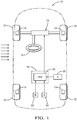
- a vehicle 10 is shown in a highly schematic manner.
- the vehicle 10 includes wheels 12 supported by a suspension 13, which may be any suitable suspension configuration.
- the suspension 13, which can include hydraulic, pneumatic and/or mechanical damping and spring elements, is of the type that can be actively stiffened or softened during vehicle operation or provide a change in ride height.
- a torque assist steering system 14 is shown that is configured to steer the front wheels 12, but all-wheel or rear-wheel steering may be provided instead, if desired.
- a driver provides a steering input to a steering wheel 16 to obtain a desired path for the vehicle.
- the vehicle 10 may be any type of vehicle with any suitable configuration.
- a lateral wind force acts on a side of the vehicle 10, which creates a high pressure relative to a pressure on the other side of the vehicle 10.
- This lateral wind force if sufficiently large, may require the operator to provide a corrective steering input to the steering system 14 to maintain the vehicle 10 along a desired path.
- the lateral wind force may require the steering system 14 to provide a steering angle correction, without any input from the vehicle operator, in order to maintain a desired path corresponding to the requested vehicle path by the driver at the steering wheel 16.
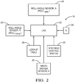
- a controller 18 includes a lane keeping system (LKS) controller 20 in communication with steering control system 30 that commands the steering system 14.
- LLS lane keeping system
- the controller 18 can be a single processor, or may comprise multiple processors distributed in the vehicle 10.
- a first roll angle sensor 22 is in communication with the LKS controller 20 and is configured to provide a first signal (ROLL body ) indicative of vehicle body roll angle R, such as by dynamically measuring vehicle body roll with a gyroscope in an inertial measurement unit.
- a lateral acceleration measurement may be used in addition to or instead of measuring roll to determine the vehicle body roll angle.
- the first signal may not be entirely attributable to vehicle roll due to the wind forces that force the vehicle from its desired path.
- a second roll angle sensor 24 is in communication with the LKS controller 20 and can be used to generate a second signal ROLL axle , which provides additional vehicle roll information relating to a position or angle A of an unsprung mass (i.e., wheels and suspension) relative to a sprung mass (i.e., vehicle body).
- An active suspension system may include sensors from which vehicle roll information can be inferred. Laterally opposing suspension components may each provide a lateral suspension position, and the second roll angle sensor may be configured to detect a change in the lateral suspension positions, which can indicate changes in road angle 34 due to bumps 32 or dips in the roadway 38 ( Fig. 3B ). In another example, at least several of the wheels 12 are driven by one or more axles, as is typical. As the vehicle 10 moves about its roll axis, the angle A changes. Such a configuration can also provide vehicle roll information. While irregularities in the roadway can affect the vehicle's path, these irregularities will not necessarily apply the same type of lateral forces to the vehicle as wind.
- detecting movement between the vehicle's sprung and unsprung masses can be used to isolate changes in the vehicle's body roll angle due to wind forces, which will provide a more accurate determination of vehicle body roll angle due to wind forces.
- a desired steering angle correction can be tailored to address the wind's effects on steering.
- Information from the first and second sensors can also be used to correct for steering disturbances due to large road camber changes if desired.
- a sensor 25 from a vision system provides a signal V that provides the roll angle of the vehicle on the roadway 32 relative to a horizon 38, as shown in Figures 3A and 3B .
- the horizon 38 corresponds to a level surface.
- the sensor 25 is a forward- or rear-facing camera, which can be used to determine a vehicle body roll angle based upon video frames of the vehicle 10 in relation to a roadway relative to the horizon or rotational component of the imagery. It should be understood that other devices may be used to determine the vehicle lateral orientation, such as radar or LIDAR.
- the sensor 25 can also detect uneven surfaces, such as drop offs or bumps, which may create a lateral force that is not attributable to lateral wind forces, thus confirming information provided by the first and second sensors 22, 24. If the vision system reveals a discrepancy in the detected vehicle will angle then information from the camera may be used instead of the 1 st sensor, for example.
- the LKS controller 20 is configured to discern effects of a lateral wind force on the vehicle in response to the first and second signals, for example, by determining the difference between the second signal and the first signal. The difference corresponds to the determined lateral wind force effects, taking out the effects of dips and bumps in the roadway.
- the LKS controller 20 is configured to produce a correction in response to the determined lateral wind force effects to maintain the vehicle along a desired path, which is requested by the driver via the steering wheel 16 by commanding a steering control system 30 in communication with the steering system 14.
- the LKS controller 20 is configured to add a wind compensation value to a commanded steering angle to maintain the vehicle along the desired path and counteract the determined wind force.
- vehicle speed (N) 26 and other variables may be used by the LKS controller 20 to determine the wind compensation value.
- Other variables may include a steering ratio (STEERING ratio ), a vehicle mass (m), and a suspension coefficient (C suspension ), and/or other vehicle dynamic characteristics. These variables may be provided to the LKS controller 20 as part of a look-up table 28.
- FIG. 4 An example method 40 of lane keeping is shown in Figure 4 .
- a vehicle body roll angle (ROLL body ) is measured (block 42), and a roll angle corresponding to a difference between the unsprung and sprung masses (ROLL axle ) is measured (block 44).
- the correction needed to maintain the vehicle along the desired path is a function of the vehicle roll angle ROLL body , the difference between the unsprung and sprung masses ROLL axle , the vehicle speed N, the steering ratio STEERING ratio , the vehicle mass m, and the suspension coefficient C suspension (block 46).
- This function is unknown, but can be identified using, for example, a fifth order system structure and an iterative least squares method (or similar method) to determine the unknown system coefficients. Additional or different vehicle dynamic characteristics may be used, if desired.
- a vehicle roll angle is also measured using the vehicle's vision system (block 45), which is used to confirm the accuracy of the determined steering angle correction (block 47).
- a wind compensation value is added to the commanded steering angle based upon the correction (block 48) if the vision system validates the steering angle correction based upon the fusion between the measured vehicle roll angles from the first and second sensors 22, 24.
- the steering correction is applied in the opposite direction of the measured roll angle to compensate for unwanted steering disturbances due to wind and large road camber changes.
- the disclosed lane keeping system and method proactively discerns the lateral wind forces from other forces on the vehicle and compensates for those wind forces that would cause the vehicle to deviate from the desired path. Confirmation of the wind-related vehicle roll can be provided using the vehicle's vision system.
- the disclosed controller 18 may include a processor and non-transitory memory where computer readable code for controlling operation is stored.
- a controller can include a processor, memory, and one or more input and/or output (I/O) device interface(s) that are communicatively coupled via a local interface.
- the local interface can include, for example but not limited to, one or more buses and/or other wired or wireless connections.
- the local interface may have additional elements, which are omitted for simplicity, such as controllers, buffers (caches), drivers, repeaters, and receivers to enable communications. Further, the local interface may include address, control, and/or data connections to enable appropriate communications among the aforementioned components.
- the controller 18 may be a hardware device for executing software, particularly software stored in memory.
- the processor can be a custom made or commercially available processor, a central processing unit (CPU), an auxiliary processor among several processors associated with the controller, a semiconductor based microprocessor (in the form of a microchip or chip set) or generally any device for executing software instructions.
- the memory can include any one or combination of volatile memory elements (e.g., random access memory (RAM, such as DRAM, SRAM, SDRAM, VRAM, etc.)) and/or nonvolatile memory elements (e.g., ROM, etc.). Moreover, the memory may incorporate electronic, magnetic, optical, and/or other types of storage media. The memory can also have a distributed architecture, where various components are situated remotely from one another, but can be accessed by the controller.
- the software in the memory may include one or more separate programs, each of which includes an ordered listing of executable instructions for implementing logical functions.
- a system component embodied as software may also be construed as a source program, executable program (object code), script, or any other entity comprising a set of instructions to be performed.
- the program is translated via a compiler, assembler, interpreter, or the like, which may or may not be included within the memory.
- the input/output devices that may be coupled to system I/O Interface(s) may include input devices, for example, but not limited to, a scanner, microphone, camera, proximity device, etc. Further, the input/output devices may also include output devices, for example but not limited to a display, etc. Finally, the input/output devices may further include devices that communicate both as inputs and outputs, for instance but not limited to, a modulator/demodulator (for accessing another device, system, or network), a radio frequency (RF) or other transceiver, a bridge, a router, etc.
- RF radio frequency
- the processor can be configured to execute software stored within the memory, to communicate data to and from the memory, and to generally control operations of the computing device pursuant to the software.
- Software in memory, in whole or in part, is read by the processor, perhaps buffered within the processor, and then executed.
Landscapes
- Engineering & Computer Science (AREA)
- Transportation (AREA)
- Mechanical Engineering (AREA)
- Combustion & Propulsion (AREA)
- Chemical & Material Sciences (AREA)
- Physics & Mathematics (AREA)
- Automation & Control Theory (AREA)
- General Physics & Mathematics (AREA)
- Remote Sensing (AREA)
- Radar, Positioning & Navigation (AREA)
- Mathematical Physics (AREA)
- Aviation & Aerospace Engineering (AREA)
- Theoretical Computer Science (AREA)
- Computer Vision & Pattern Recognition (AREA)
- Vehicle Body Suspensions (AREA)
- Control Of Driving Devices And Active Controlling Of Vehicle (AREA)
- Business, Economics & Management (AREA)
- Health & Medical Sciences (AREA)
- Artificial Intelligence (AREA)
- Evolutionary Computation (AREA)
- Game Theory and Decision Science (AREA)
- Medical Informatics (AREA)
Abstract
A lane keeping system for a vehicle (10) includes a first roll angle sensor (22) configured to provide a first signal indicative of dynamic vehicle body roll. A second roll angle sensor (24) is configured to provide a second signal indicative of an angle between vehicle sprung and unsprung masses. A lane keeping system (LKS) controller (18) is in communication with the first and second roll angle sensors. The Iks controller (20) is configured to discern a vehicle roll angle in response to the first and second signals based upon effects of a lateral wind force on the vehicle (10). The Iks controller (20) is configured to produce a correction in response to the determined lateral wind force effects to maintain the vehicle (10) along a desired path.
Description
- This disclosure relates to a lane keeping system in a fully autonomous vehicle or a vehicle that is driver-assisted. The disclosed system maintains the vehicle in its lane when subjected to differential lateral forces, such as when the vehicle is buffeted by winds.
- During abnormally windy conditions a vehicle is buffeted causing discomfort to the driver and occupants. Wind disturbances may be steady, gusty, or caused by wind shadowed areas or passing vehicles. In all cases the vehicle is buffeted due to lateral wind pressure onto the vehicle. Wind gusts can induce lateral forces from zero to hundreds of pounds in short bursts or by slowly changing conditions. In some circumstances, lane deflection of 10-20 cm have been observed due to wind gusts.
- A typical automated lane keeping system uses a closed loop system to maintain vehicle position relative to the lane while the vehicle is driven on a roadway. These systems have been improved upon by providing steering correction inputs due to wind forces, but they have been costly due to required additional components or have been difficult to implement.
- There are systems that measure roll angle or lateral acceleration, but these systems do not offer a means of determining the effects of lateral wind forces on the vehicle specifically. Other systems measure roll angle, lateral acceleration or wind conditions, but do so to determine an optimal or new path rather than maintain the path desired by the occupant, much like an obstacle avoidance system.
- In one exemplary embodiment, a lane keeping system for a vehicle includes a first roll angle sensor configured to provide a first signal indicative of dynamic vehicle body roll. A second roll angle sensor is configured to provide a second signal indicative of an angle between vehicle sprung and unsprung masses. A lane keeping system (LKS) controller is in communication with the first and second roll angle sensors. The LKS controller is configured to discern a vehicle roll angle in response to the first and second signals based upon effects of a lateral wind force on the vehicle. The LKS controller is configured to produce a correction in response to the determined lateral wind force effects to maintain the vehicle along a desired path.
- In a further embodiment of the above, a vision system sensor is in communication with the LKS controller and is configured to confirm accuracy of the vehicle roll angle.
- In a further embodiment of any of the above, the vision system sensor includes a camera. The LKS controller is configured to confirm accuracy of the vehicle roll angle based upon video frames of the vehicle in relation to a roadway relative to a known horizon.
- In a further embodiment of any of the above, the first roll angle sensor includes a gyroscope.
- In a further embodiment of any of the above, the second roll angle sensor is a drivetrain that includes an axle that has an axle angle. The second roll angle sensor is configured to detect a change in the axle angle.
- In a further embodiment of any of the above, the second roll angle sensor is a suspension system that includes laterally opposing suspension components that each provide a lateral suspension position. The second roll angle sensor is configured to detect a change in the lateral suspension positions.
- In a further embodiment of any of the above, the LKS controller is configured to determine a difference between the second signal and the first signal. The difference corresponds to the determined lateral wind force effects.
- In a further embodiment of any of the above, a steering system is in communication with the LKS controller. The LKS controller is configured to add a wind compensation value to a commanded steering angle to maintain the vehicle along the desired path and counteract the determined lateral wind force effects.
- In a further embodiment of any of the above, the correction is a function of the vehicle roll angle, a difference between the unsprung and sprung masses, a vehicle speed, a steering ratio, a vehicle mass, and a suspension coefficient.
- In another exemplary embodiment, a method of maintaining a vehicle along a desired path includes the steps of determining a vehicle dynamic body roll and determining an angle between vehicle sprung and unsprung masses. Effects of lateral wind force are discerned to produce a correction based upon the determining steps. A wind compensation value is added to a commanded steering angle based upon the correction.
- In a further embodiment of any of the above, the determining steps include providing a vehicle roll angle and comprising the step of confirming accuracy of the vehicle roll angle.
- In a further embodiment of any of the above, the step of determining a vehicle lateral orientation relative to a horizon to confirm the accuracy of the vehicle roll angle provided by first and second roll angle sensors associated with the determining steps.
- In a further embodiment of any of the above, the horizon is determined based upon video frames of the vehicle from a camera in relation to a roadway relative to a known horizon.
- In a further embodiment of any of the above, the vehicle dynamic body roll determining step is performed using an inertial measurement unit.
- In a further embodiment of any of the above, the inertial measurement unit includes a gyroscope.
- In a further embodiment of any of the above, the angle determining step is performed using a second roll angle sensor. The second roll angle sensor is a drivetrain that includes an axle that has an axle angle. The second roll angle sensor is configured to detect a change in the axle angle.
- In a further embodiment of any of the above, angle determining step is performed using a second roll angle sensor. The second roll angle sensor is a suspension system that includes laterally opposing suspension components that each provide a lateral suspension position. The second roll angle sensor is configured to detect a change in the lateral suspension positions.
- In a further embodiment of any of the above, a lane keeping system (LKS) controller is configured to quantify a difference between the determining steps. The difference corresponds to the discerned lateral wind force effects.
- In a further embodiment of any of the above, a steering system is in communication with the LKS controller. The LKS controller is configured to add a wind compensation value to a commanded steering angle to maintain the vehicle along a desired path and counteract the discerned lateral wind force effects.
- In a further embodiment of any of the above, the correction is a function of the vehicle roll angle, a difference between the unsprung and sprung masses, a vehicle speed, a steering ratio, a vehicle mass, and a suspension coefficient.
- The disclosure can be further understood by reference to the following detailed description when considered in connection with the accompanying drawings wherein:
-
Figure 1 is a schematic view of a vehicle with a lane keeping system relating to lateral wind forces. -
Figure 2 is a schematic view of the lane keeping system with various inputs. -
Figure 3A is a schematic side view of the vehicle. -
Figure 3B is a schematic rear view of the vehicle shown inFigure 3A . -
Figure 4 is a flowchart depicting a method of lane keeping using the system shown inFigures 1-2 . - The embodiments, examples and alternatives of the preceding paragraphs, the claims, or the following description and drawings, including any of their various aspects or respective individual features, may be taken independently or in any combination. Features described in connection with one embodiment are applicable to all embodiments, unless such features are incompatible.
- With the introduction of partially or fully automated vehicle control, the capability exists for enhanced vehicle control and safety using lateral force sensing. By using lateral force sensing, the vehicle path can proactively adjust to lateral disturbances rather than simply reacting after the lateral force has drifted the vehicle off course. Wind correction data is available instantaneously as opposed to a reactionary system, which for an autonomous system, may be hundreds of milliseconds delay.
- The disclosed system and method improves vehicle comfort by using first and second roll angle sensors and a control system that makes corrections to the steering angle before the vehicle drifts off course due to lateral wind forces. A vision system can also be used to confirm the accuracy of the roll angle from the roll angle and lateral acceleration sensors. The lateral wind detection can be used to reduce user-provided wind steering counter-torque in modern manual torque assist steering systems, for example, as part of a lane keeping system or an autonomously operated vehicle.
- Referring to
Figure 1 , avehicle 10 is shown in a highly schematic manner. Thevehicle 10 includeswheels 12 supported by asuspension 13, which may be any suitable suspension configuration. In one example, thesuspension 13, which can include hydraulic, pneumatic and/or mechanical damping and spring elements, is of the type that can be actively stiffened or softened during vehicle operation or provide a change in ride height. - A torque
assist steering system 14 is shown that is configured to steer thefront wheels 12, but all-wheel or rear-wheel steering may be provided instead, if desired. A driver provides a steering input to asteering wheel 16 to obtain a desired path for the vehicle. It should be understood that thevehicle 10 may be any type of vehicle with any suitable configuration. - A lateral wind force (horizontal arrows) acts on a side of the
vehicle 10, which creates a high pressure relative to a pressure on the other side of thevehicle 10. This lateral wind force, if sufficiently large, may require the operator to provide a corrective steering input to thesteering system 14 to maintain thevehicle 10 along a desired path. In the case of a lane keeping system or an autonomous vehicle, the lateral wind force may require thesteering system 14 to provide a steering angle correction, without any input from the vehicle operator, in order to maintain a desired path corresponding to the requested vehicle path by the driver at thesteering wheel 16. - Referring to
Figures 1 and2 , acontroller 18 includes a lane keeping system (LKS)controller 20 in communication withsteering control system 30 that commands thesteering system 14. Thecontroller 18 can be a single processor, or may comprise multiple processors distributed in thevehicle 10. - A first
roll angle sensor 22 is in communication with theLKS controller 20 and is configured to provide a first signal (ROLLbody) indicative of vehicle body roll angle R, such as by dynamically measuring vehicle body roll with a gyroscope in an inertial measurement unit. A lateral acceleration measurement may be used in addition to or instead of measuring roll to determine the vehicle body roll angle. However, the first signal may not be entirely attributable to vehicle roll due to the wind forces that force the vehicle from its desired path. - A second
roll angle sensor 24 is in communication with theLKS controller 20 and can be used to generate a second signal ROLLaxle, which provides additional vehicle roll information relating to a position or angle A of an unsprung mass (i.e., wheels and suspension) relative to a sprung mass (i.e., vehicle body). - An active suspension system may include sensors from which vehicle roll information can be inferred. Laterally opposing suspension components may each provide a lateral suspension position, and the second roll angle sensor may be configured to detect a change in the lateral suspension positions, which can indicate changes in
road angle 34 due tobumps 32 or dips in the roadway 38 (Fig. 3B ). In another example, at least several of thewheels 12 are driven by one or more axles, as is typical. As thevehicle 10 moves about its roll axis, the angle A changes. Such a configuration can also provide vehicle roll information. While irregularities in the roadway can affect the vehicle's path, these irregularities will not necessarily apply the same type of lateral forces to the vehicle as wind. Thus, detecting movement between the vehicle's sprung and unsprung masses can be used to isolate changes in the vehicle's body roll angle due to wind forces, which will provide a more accurate determination of vehicle body roll angle due to wind forces. Thus, a desired steering angle correction can be tailored to address the wind's effects on steering. Information from the first and second sensors can also be used to correct for steering disturbances due to large road camber changes if desired. - A
sensor 25 from a vision system provides a signal V that provides the roll angle of the vehicle on theroadway 32 relative to ahorizon 38, as shown inFigures 3A and 3B . Thehorizon 38 corresponds to a level surface. In one example, thesensor 25 is a forward- or rear-facing camera, which can be used to determine a vehicle body roll angle based upon video frames of thevehicle 10 in relation to a roadway relative to the horizon or rotational component of the imagery. It should be understood that other devices may be used to determine the vehicle lateral orientation, such as radar or LIDAR. Thesensor 25 can also detect uneven surfaces, such as drop offs or bumps, which may create a lateral force that is not attributable to lateral wind forces, thus confirming information provided by the first andsecond sensors - The
LKS controller 20 is configured to discern effects of a lateral wind force on the vehicle in response to the first and second signals, for example, by determining the difference between the second signal and the first signal. The difference corresponds to the determined lateral wind force effects, taking out the effects of dips and bumps in the roadway. TheLKS controller 20 is configured to produce a correction in response to the determined lateral wind force effects to maintain the vehicle along a desired path, which is requested by the driver via thesteering wheel 16 by commanding asteering control system 30 in communication with thesteering system 14. TheLKS controller 20 is configured to add a wind compensation value to a commanded steering angle to maintain the vehicle along the desired path and counteract the determined wind force. - Referring to
Figure 2 , vehicle speed (N) 26 and other variables may be used by theLKS controller 20 to determine the wind compensation value. Other variables may include a steering ratio (STEERINGratio), a vehicle mass (m), and a suspension coefficient (Csuspension), and/or other vehicle dynamic characteristics. These variables may be provided to theLKS controller 20 as part of a look-up table 28. - An
example method 40 of lane keeping is shown inFigure 4 . A vehicle body roll angle (ROLLbody) is measured (block 42), and a roll angle corresponding to a difference between the unsprung and sprung masses (ROLLaxle) is measured (block 44). The correction needed to maintain the vehicle along the desired path is a function of the vehicle roll angle ROLLbody, the difference between the unsprung and sprung masses ROLLaxle, the vehicle speed N, the steering ratio STEERINGratio, the vehicle mass m, and the suspension coefficient Csuspension (block 46). This function is unknown, but can be identified using, for example, a fifth order system structure and an iterative least squares method (or similar method) to determine the unknown system coefficients. Additional or different vehicle dynamic characteristics may be used, if desired. - A vehicle roll angle is also measured using the vehicle's vision system (block 45), which is used to confirm the accuracy of the determined steering angle correction (block 47). A wind compensation value is added to the commanded steering angle based upon the correction (block 48) if the vision system validates the steering angle correction based upon the fusion between the measured vehicle roll angles from the first and
second sensors - The disclosed lane keeping system and method proactively discerns the lateral wind forces from other forces on the vehicle and compensates for those wind forces that would cause the vehicle to deviate from the desired path. Confirmation of the wind-related vehicle roll can be provided using the vehicle's vision system.
- The disclosed
controller 18 may include a processor and non-transitory memory where computer readable code for controlling operation is stored. In terms of hardware architecture, such a controller can include a processor, memory, and one or more input and/or output (I/O) device interface(s) that are communicatively coupled via a local interface. The local interface can include, for example but not limited to, one or more buses and/or other wired or wireless connections. The local interface may have additional elements, which are omitted for simplicity, such as controllers, buffers (caches), drivers, repeaters, and receivers to enable communications. Further, the local interface may include address, control, and/or data connections to enable appropriate communications among the aforementioned components. - The
controller 18 may be a hardware device for executing software, particularly software stored in memory. The processor can be a custom made or commercially available processor, a central processing unit (CPU), an auxiliary processor among several processors associated with the controller, a semiconductor based microprocessor (in the form of a microchip or chip set) or generally any device for executing software instructions. - The memory can include any one or combination of volatile memory elements (e.g., random access memory (RAM, such as DRAM, SRAM, SDRAM, VRAM, etc.)) and/or nonvolatile memory elements (e.g., ROM, etc.). Moreover, the memory may incorporate electronic, magnetic, optical, and/or other types of storage media. The memory can also have a distributed architecture, where various components are situated remotely from one another, but can be accessed by the controller.
- The software in the memory may include one or more separate programs, each of which includes an ordered listing of executable instructions for implementing logical functions. A system component embodied as software may also be construed as a source program, executable program (object code), script, or any other entity comprising a set of instructions to be performed. When constructed as a source program, the program is translated via a compiler, assembler, interpreter, or the like, which may or may not be included within the memory.
- The input/output devices that may be coupled to system I/O Interface(s) may include input devices, for example, but not limited to, a scanner, microphone, camera, proximity device, etc. Further, the input/output devices may also include output devices, for example but not limited to a display, etc. Finally, the input/output devices may further include devices that communicate both as inputs and outputs, for instance but not limited to, a modulator/demodulator (for accessing another device, system, or network), a radio frequency (RF) or other transceiver, a bridge, a router, etc.
- When the
controller 18 is in operation, the processor can be configured to execute software stored within the memory, to communicate data to and from the memory, and to generally control operations of the computing device pursuant to the software. Software in memory, in whole or in part, is read by the processor, perhaps buffered within the processor, and then executed. - It should also be understood that although a particular component arrangement is disclosed in the illustrated embodiment, other arrangements will benefit herefrom. Although particular step sequences are shown, described, and claimed, it should be understood that steps may be performed in any order, separated or combined unless otherwise indicated and will still benefit from the present invention.
- Although the different examples have specific components shown in the illustrations, embodiments of this invention are not limited to those particular combinations. It is possible to use some of the components or features from one of the examples in combination with features or components from another one of the examples.
- Although an example embodiment has been disclosed, a worker of ordinary skill in this art would recognize that certain modifications would come within the scope of the claims. For that reason, the following claims should be studied to determine their true scope and content.
Claims (14)
- A lane keeping system for a vehicle (10) comprising:a first roll angle sensor (22) configured to provide a first signal indicative of dynamic vehicle body roll;a second roll angle sensor (24) configured to provide a second signal indicative of an angle between vehicle sprung and unsprung masses; anda lane keeping system (LKS) controller (18) in communication with the first and second roll angle sensors, the lks controller (20) configured to discern a vehicle roll angle in response to the first and second signals based upon effects of a lateral wind force on the vehicle (10), the Iks controller (20) configured to produce a correction in response to the determined lateral wind force effects to maintain the vehicle (10) along a desired path.
- The system according to claim 1, comprising a vision system sensor (25) in communication with the Iks controller (20) and configured to confirm accuracy of the vehicle roll angle.
- The system according to claim 2, wherein the vision system sensor (25) includes a camera, and the Iks controller (20) is configured to confirm accuracy of the vehicle roll angle based upon video frames of the vehicle (10) in relation to a roadway (32) relative to a known horizon (38).
- The system according to any one of claims 1 to 3, wherein the first roll angle sensor (22) includes a gyroscope.
- The system according to any one of claims 1 to 4, wherein the second roll angle sensor (24) is a drivetrain that includes an axle having an axle angle, and the second roll angle sensor (24) is configured to detect a change in the axle angle.
- The system according to any one of claims 1 to 4, wherein the second roll angle sensor (24) is a suspension (13) system that includes laterally opposing suspension components that each provide a lateral suspension position, and the second roll angle sensor (24) is configured to detect a change in the lateral suspension positions.
- The system according to any one of claims 1 to 6, wherein the Iks controller (20) is configured to determine a difference between the second signal and the first signal, the difference corresponding to the determined lateral wind force effects.
- The system according to any one of claims 1 to 7, comprising a steering system (14) in communication with the Iks controller (20), the Iks controller (20) configured to add a wind compensation value to a commanded steering angle to maintain the vehicle (10) along the desired path and counteract the determined lateral wind force effects.
- The system according to claim 8, wherein the correction is a function of the vehicle roll angle, a difference between the unsprung and sprung masses, a vehicle speed, a steering ratio, a vehicle mass, and a suspension coefficient.
- A method (40) of maintaining a vehicle (10) along a desired path comprising the steps of:determining a vehicle dynamic body roll;determining an angle between vehicle sprung and unsprung masses;discerning effects of lateral wind force to produce a correction based upon the determining steps; andadding a wind compensation value to a commanded steering angle based upon the correction.
- The method (40) according to claim 10, wherein the determining steps include providing a vehicle roll angle, and comprising the step of confirming accuracy of the vehicle roll angle.
- The method (40) according to claim 11, comprising the step of determining a vehicle lateral orientation relative to a horizon (38) to confirm the accuracy of the vehicle roll angle provided by first and second roll angle sensors associated with the determining steps.
- The method (40) according to claim 12, wherein the horizon (38) is determined based upon video frames of the vehicle (10) from a camera in relation to a roadway (32) relative to a known horizon (38).
- The method (40) according to any one of claims 10 to 13, wherein the vehicle dynamic body roll determining step is performed using an inertial measurement unit.
Applications Claiming Priority (1)
| Application Number | Priority Date | Filing Date | Title |
|---|---|---|---|
| US15/227,597 US10179607B2 (en) | 2016-08-03 | 2016-08-03 | Lane keeping system for autonomous vehicle in wind conditions using vehicle roll |
Publications (1)
| Publication Number | Publication Date |
|---|---|
| EP3279062A1 true EP3279062A1 (en) | 2018-02-07 |
Family
ID=59325228
Family Applications (1)
| Application Number | Title | Priority Date | Filing Date |
|---|---|---|---|
| EP17181020.3A Withdrawn EP3279062A1 (en) | 2016-08-03 | 2017-07-12 | Lane keeping system for vehicle in wind conditions using vehicle roll |
Country Status (3)
| Country | Link |
|---|---|
| US (1) | US10179607B2 (en) |
| EP (1) | EP3279062A1 (en) |
| CN (1) | CN107685730B (en) |
Cited By (2)
| Publication number | Priority date | Publication date | Assignee | Title |
|---|---|---|---|---|
| GB2574258A (en) * | 2018-06-01 | 2019-12-04 | Jaguar Land Rover Ltd | An apparatus and a method for controlling steering |
| WO2023057122A1 (en) * | 2021-10-09 | 2023-04-13 | Robert Bosch Gmbh | Lateral interference prevention module and method for vehicle |
Families Citing this family (13)
| Publication number | Priority date | Publication date | Assignee | Title |
|---|---|---|---|---|
| US10976745B2 (en) * | 2018-02-09 | 2021-04-13 | GM Global Technology Operations LLC | Systems and methods for autonomous vehicle path follower correction |
| CN117565968A (en) * | 2018-06-01 | 2024-02-20 | 捷豹路虎有限公司 | Devices, systems and methods for controlling vehicle steering and vehicles |
| US11117589B2 (en) * | 2019-01-29 | 2021-09-14 | GM Global Technology Operations LLC | System and method for determining roadway bank angle |
| JP2020152222A (en) * | 2019-03-20 | 2020-09-24 | 本田技研工業株式会社 | Vehicle control devices, vehicle control methods, and programs |
| JP7318332B2 (en) * | 2019-06-13 | 2023-08-01 | 株式会社ジェイテクト | Crosswind effect estimation device and vehicle control device |
| JP2021011152A (en) * | 2019-07-04 | 2021-02-04 | 本田技研工業株式会社 | Vehicle control devices, vehicle control methods, and programs |
| WO2021041848A1 (en) * | 2019-08-28 | 2021-03-04 | Continental Automotive Systems, Inc. | Disturbance handling for trailer towing |
| KR102869195B1 (en) * | 2019-09-27 | 2025-10-13 | 현대자동차주식회사 | Vehicle stability management |
| CN110722949B (en) * | 2019-10-22 | 2021-06-29 | 北京经纬恒润科技股份有限公司 | Crosswind compensation method of vehicle, suspension controller and steering controller |
| CN111025959B (en) * | 2019-11-20 | 2021-10-01 | 华为技术有限公司 | A data management method, device, equipment and smart car |
| US12246751B1 (en) * | 2021-04-26 | 2025-03-11 | Zoox, Inc. | Trajectory modification based on wind compensation |
| US11760348B2 (en) * | 2021-09-27 | 2023-09-19 | Ford Global Technologies, Llc | Vehicle boundary control |
| JP7801155B2 (en) * | 2022-03-16 | 2026-01-16 | 株式会社Subaru | Vehicle driving assistance device |
Citations (5)
| Publication number | Priority date | Publication date | Assignee | Title |
|---|---|---|---|---|
| WO2000038939A1 (en) * | 1998-12-29 | 2000-07-06 | Volvo Personvagnar Ab | Wheel suspension arrangement in a vehicle |
| WO2005097578A1 (en) * | 2004-04-10 | 2005-10-20 | Daimlerchrysler Ag | Device and method for a vehicle for determination of at least one value for a sidewind |
| DE102004033731A1 (en) * | 2004-07-13 | 2006-02-02 | Adam Opel Ag | Automatically correcting influence of side wind on motor vehicle, by comparing signal from existing lane departing warning system with signal from steering sensor |
| WO2007044744A2 (en) * | 2005-10-11 | 2007-04-19 | Ford Global Technologies, Llc. | Enhanced yaw stability control to mitigate a vehicle's abnormal yaw motion due to a disturbance force applied to vehicle body |
| US20100157058A1 (en) * | 2008-11-20 | 2010-06-24 | Hella Kgaa Hueck & Co. | Method and Device for Compensating a Roll Angle |
Family Cites Families (20)
| Publication number | Priority date | Publication date | Assignee | Title |
|---|---|---|---|---|
| DE4127725A1 (en) * | 1991-08-22 | 1993-02-25 | Porsche Ag | METHOD AND DEVICE FOR MINIMIZING THE SIDEWIND INFLUENCE ON THE DRIVING BEHAVIOR OF A VEHICLE |
| JPH1148734A (en) * | 1997-08-05 | 1999-02-23 | Unisia Jecs Corp | Vehicle suspension system |
| AU2002354225A1 (en) * | 2002-12-18 | 2004-07-09 | Satoru Kojima | Roll angle controller for remote-controlled traveling body, and roll angle controller for remote-controlled motor cycle |
| JP4715351B2 (en) * | 2005-07-19 | 2011-07-06 | 株式会社デンソー | Steering control system |
| KR100761011B1 (en) * | 2006-05-30 | 2007-09-21 | 학교법인 인하학원 | Posture Correction Apparatus and Method for Inertial Navigation System Using Camera-type Solar Sensor |
| US8740285B2 (en) * | 2008-10-14 | 2014-06-03 | William Nelson Beckon | Vehicle airfoils for safety, efficiency, and performance |
| EP2452841B1 (en) * | 2009-07-08 | 2017-10-18 | Toyota Jidosha Kabushiki Kaisha | Vehicular damper system |
| US20130009350A1 (en) * | 2011-07-08 | 2013-01-10 | Friedrich Peter Wolf-Monheim | Semiactive Wheel Suspension |
| KR101859759B1 (en) * | 2011-10-11 | 2018-05-21 | 현대모비스 주식회사 | Method for compensating side-wind based on Camera sensor of LKAS in MotorDriven Power Steering |
| US8985594B2 (en) * | 2012-01-11 | 2015-03-24 | Toyota Jidosha Kabushiki Kaisha | Vehicle |
| EP2868499B1 (en) * | 2012-06-29 | 2018-11-21 | Honda Motor Co., Ltd. | Suspension control device |
| JP5740358B2 (en) * | 2012-06-29 | 2015-06-24 | 本田技研工業株式会社 | Suspension control device |
| CN104837706B (en) * | 2012-12-11 | 2017-05-24 | 丰田自动车株式会社 | Vehicle status detection device |
| JP5983597B2 (en) * | 2013-12-26 | 2016-08-31 | トヨタ自動車株式会社 | Vehicle state estimation device, vehicle state estimation method, and vehicle control device |
| JP6003931B2 (en) * | 2014-03-11 | 2016-10-05 | トヨタ自動車株式会社 | Vehicle state estimation device, vehicle control device, and vehicle state estimation method |
| JP5841200B1 (en) * | 2014-07-08 | 2016-01-13 | Kyb株式会社 | Signal processing apparatus, suspension control apparatus, and signal processing method |
| US20160096546A1 (en) * | 2014-10-03 | 2016-04-07 | Delphi Technologies, Inc. | Lane departure steering correction with road camber and crosswind compensation |
| FR3034681B1 (en) * | 2015-04-10 | 2017-05-12 | Parrot | DRONE DRIVING SYSTEM IN IMMERSION. |
| JP6245217B2 (en) * | 2015-05-19 | 2017-12-13 | トヨタ自動車株式会社 | Vehicle state quantity estimation device |
| US9934559B2 (en) * | 2016-02-19 | 2018-04-03 | Fotonation Limited | Method for correcting an acquired image |
-
2016
- 2016-08-03 US US15/227,597 patent/US10179607B2/en active Active
-
2017
- 2017-07-12 EP EP17181020.3A patent/EP3279062A1/en not_active Withdrawn
- 2017-08-02 CN CN201710652955.9A patent/CN107685730B/en active Active
Patent Citations (5)
| Publication number | Priority date | Publication date | Assignee | Title |
|---|---|---|---|---|
| WO2000038939A1 (en) * | 1998-12-29 | 2000-07-06 | Volvo Personvagnar Ab | Wheel suspension arrangement in a vehicle |
| WO2005097578A1 (en) * | 2004-04-10 | 2005-10-20 | Daimlerchrysler Ag | Device and method for a vehicle for determination of at least one value for a sidewind |
| DE102004033731A1 (en) * | 2004-07-13 | 2006-02-02 | Adam Opel Ag | Automatically correcting influence of side wind on motor vehicle, by comparing signal from existing lane departing warning system with signal from steering sensor |
| WO2007044744A2 (en) * | 2005-10-11 | 2007-04-19 | Ford Global Technologies, Llc. | Enhanced yaw stability control to mitigate a vehicle's abnormal yaw motion due to a disturbance force applied to vehicle body |
| US20100157058A1 (en) * | 2008-11-20 | 2010-06-24 | Hella Kgaa Hueck & Co. | Method and Device for Compensating a Roll Angle |
Cited By (3)
| Publication number | Priority date | Publication date | Assignee | Title |
|---|---|---|---|---|
| GB2574258A (en) * | 2018-06-01 | 2019-12-04 | Jaguar Land Rover Ltd | An apparatus and a method for controlling steering |
| GB2574258B (en) * | 2018-06-01 | 2021-11-10 | Jaguar Land Rover Ltd | Steering control dependent on roll angle |
| WO2023057122A1 (en) * | 2021-10-09 | 2023-04-13 | Robert Bosch Gmbh | Lateral interference prevention module and method for vehicle |
Also Published As
| Publication number | Publication date |
|---|---|
| US20180037259A1 (en) | 2018-02-08 |
| US10179607B2 (en) | 2019-01-15 |
| CN107685730A (en) | 2018-02-13 |
| CN107685730B (en) | 2020-05-22 |
Similar Documents
| Publication | Publication Date | Title |
|---|---|---|
| US10179607B2 (en) | Lane keeping system for autonomous vehicle in wind conditions using vehicle roll | |
| US9796421B1 (en) | Autonomous vehicle lateral control for path tracking and stability | |
| US7480547B2 (en) | Attitude sensing system for an automotive vehicle relative to the road | |
| EP3248857B1 (en) | Lane keeping system for autonomous vehicle in wind conditions | |
| US6684140B2 (en) | System for sensing vehicle global and relative attitudes using suspension height sensors | |
| US10106167B2 (en) | Control system and method for determining an irregularity of a road surface | |
| JP7248738B2 (en) | Method for partially or fully autonomous steering of a vehicle | |
| CN114423655B (en) | Method for adjusting the lateral position of a motor vehicle | |
| US10899349B2 (en) | Centering a vehicle in a lane using environmental information to correct a predicted trajectory | |
| CN107257748A (en) | Method for compensating gradient | |
| KR20220075353A (en) | A device for controlling the steering angle of an autonomous vehicle | |
| US20160001626A1 (en) | Method for adjusting a roll moment of an axle of a vehicle for roll stabilization | |
| US20210370738A1 (en) | Damping control device and damping control method | |
| JP2022013714A5 (en) | ||
| CN112660044A (en) | System for stabilizing an image of a display in a vehicle | |
| US11919582B2 (en) | Methods, systems, and apparatuses for real-time adaptation of handwheel angle controls for robust automated driving to environmental conditions and model uncertainties | |
| JP7602614B2 (en) | Vehicle control device, vehicle control method, and vehicle control system | |
| US11840293B2 (en) | Turning system for vehicle | |
| JP4696671B2 (en) | Vehicle control device | |
| US20110172872A1 (en) | Apparatus for determining turning vehicle condition | |
| JP2020082751A (en) | Vehicular automatic steering control apparatus | |
| JP2007240392A (en) | Ground load estimation device | |
| WO2025094454A1 (en) | Vehicle control device, vehicle control method, vehicle control program, and rear wheel steering device | |
| WO2017095301A1 (en) | Method and system for facilitating steering of a vehicle during driving along a road | |
| CN120902719B (en) | Vehicle anti-roll cooperative control method and device, electronic equipment and storage medium |
Legal Events
| Date | Code | Title | Description |
|---|---|---|---|
| PUAI | Public reference made under article 153(3) epc to a published international application that has entered the european phase |
Free format text: ORIGINAL CODE: 0009012 |
|
| AK | Designated contracting states |
Kind code of ref document: A1 Designated state(s): AL AT BE BG CH CY CZ DE DK EE ES FI FR GB GR HR HU IE IS IT LI LT LU LV MC MK MT NL NO PL PT RO RS SE SI SK SM TR |
|
| AX | Request for extension of the european patent |
Extension state: BA ME |
|
| STAA | Information on the status of an ep patent application or granted ep patent |
Free format text: STATUS: THE APPLICATION IS DEEMED TO BE WITHDRAWN |
|
| 18D | Application deemed to be withdrawn |
Effective date: 20180808 |