EP3279028A1 - Seat support apparatus - Google Patents
Seat support apparatus Download PDFInfo
- Publication number
- EP3279028A1 EP3279028A1 EP16772986.2A EP16772986A EP3279028A1 EP 3279028 A1 EP3279028 A1 EP 3279028A1 EP 16772986 A EP16772986 A EP 16772986A EP 3279028 A1 EP3279028 A1 EP 3279028A1
- Authority
- EP
- European Patent Office
- Prior art keywords
- base
- cable
- paddle
- seat
- seat support
- Prior art date
- Legal status (The legal status is an assumption and is not a legal conclusion. Google has not performed a legal analysis and makes no representation as to the accuracy of the status listed.)
- Withdrawn
Links
- 230000006835 compression Effects 0.000 claims description 31
- 238000007906 compression Methods 0.000 claims description 31
- 230000015572 biosynthetic process Effects 0.000 description 11
- 238000003780 insertion Methods 0.000 description 3
- 230000037431 insertion Effects 0.000 description 3
- 230000008602 contraction Effects 0.000 description 2
- 238000010586 diagram Methods 0.000 description 2
- 239000000463 material Substances 0.000 description 2
- 239000011347 resin Substances 0.000 description 1
- 229920005989 resin Polymers 0.000 description 1
Images


Classifications
-
- B—PERFORMING OPERATIONS; TRANSPORTING
- B60—VEHICLES IN GENERAL
- B60N—SEATS SPECIALLY ADAPTED FOR VEHICLES; VEHICLE PASSENGER ACCOMMODATION NOT OTHERWISE PROVIDED FOR
- B60N2/00—Seats specially adapted for vehicles; Arrangement or mounting of seats in vehicles
- B60N2/90—Details or parts not otherwise provided for
- B60N2/914—Hydro-pneumatic adjustments of the shape
-
- A—HUMAN NECESSITIES
- A47—FURNITURE; DOMESTIC ARTICLES OR APPLIANCES; COFFEE MILLS; SPICE MILLS; SUCTION CLEANERS IN GENERAL
- A47C—CHAIRS; SOFAS; BEDS
- A47C7/00—Parts, details, or accessories of chairs or stools
- A47C7/36—Supports for the head or the back
- A47C7/40—Supports for the head or the back for the back
-
- B—PERFORMING OPERATIONS; TRANSPORTING
- B60—VEHICLES IN GENERAL
- B60N—SEATS SPECIALLY ADAPTED FOR VEHICLES; VEHICLE PASSENGER ACCOMMODATION NOT OTHERWISE PROVIDED FOR
- B60N2/00—Seats specially adapted for vehicles; Arrangement or mounting of seats in vehicles
- B60N2/02—Seats specially adapted for vehicles; Arrangement or mounting of seats in vehicles the seat or part thereof being movable, e.g. adjustable
- B60N2/22—Seats specially adapted for vehicles; Arrangement or mounting of seats in vehicles the seat or part thereof being movable, e.g. adjustable the back-rest being adjustable
-
- B—PERFORMING OPERATIONS; TRANSPORTING
- B60—VEHICLES IN GENERAL
- B60N—SEATS SPECIALLY ADAPTED FOR VEHICLES; VEHICLE PASSENGER ACCOMMODATION NOT OTHERWISE PROVIDED FOR
- B60N2/00—Seats specially adapted for vehicles; Arrangement or mounting of seats in vehicles
- B60N2/02—Seats specially adapted for vehicles; Arrangement or mounting of seats in vehicles the seat or part thereof being movable, e.g. adjustable
- B60N2/22—Seats specially adapted for vehicles; Arrangement or mounting of seats in vehicles the seat or part thereof being movable, e.g. adjustable the back-rest being adjustable
- B60N2/2222—Seats specially adapted for vehicles; Arrangement or mounting of seats in vehicles the seat or part thereof being movable, e.g. adjustable the back-rest being adjustable the back-rest having two or more parts
-
- B—PERFORMING OPERATIONS; TRANSPORTING
- B60—VEHICLES IN GENERAL
- B60N—SEATS SPECIALLY ADAPTED FOR VEHICLES; VEHICLE PASSENGER ACCOMMODATION NOT OTHERWISE PROVIDED FOR
- B60N2/00—Seats specially adapted for vehicles; Arrangement or mounting of seats in vehicles
- B60N2/90—Details or parts not otherwise provided for
- B60N2/986—Side-rests
- B60N2/99—Side-rests adjustable
Definitions
- the present invention relates to a seat support device.
- a pneumatic seat support device can change a support shape of a seat by deploying an airbag, which is arranged inside the seat, to push a seat pad. Further, such a seat support device usually includes a movable member that is moved by the expansion and contraction of the airbag, a fixed member, and an elastic member arranged between the movable member and the fixed member.
- Patent document 1 describes an example of a seat support device including a helical extension spring arranged between the movable member and the fixed member. When the airbag contracts, the elastic force of the helical extension spring returns the movable member to its initial position.
- Patent Document 1 Japanese National Phase Laid-Open Patent Publication No. 2008-541896
- the seat support device of patent document 1 can move the movable member in a limitless manner against the biasing force of the elastic member. This may, for example, reduce the resilient force of the elastic member or separate the movable member.
- a seat support device that solves the above problem includes a base, a paddle, an airbag, and a cable.
- the base is fixed to an inner side of a seat.
- the paddle is movable toward and away from the base.
- the airbag is arranged between the base and the paddle. The airbag pushes a seat pad of the seat with the paddle when deployed.
- the cable includes a first end engaged with the base and a second end engaged with the paddle.
- a vehicle seat 1 includes a seat cushion 2, a seat back 3 arranged at a rear end of the seat cushion 2 in an inclinable manner, and a head rest 4 arranged at an upper end of the seat back 3.
- a plurality of seat support devices 10 (10A, 10B) are arranged in the seat back 3.
- the seat back 3 includes seat back side portions 3a and 3b and a seat back shoulder portion 3c, each having a frontward bulging support shape. This ensures a satisfactory seating position for the vehicle occupant who is seated on the seat 1 and kept at the seating position.
- Each of the support devices 10 (10A, 10B) includes an airbag 5 (5a to 5c) arranged inside the seat back 3.
- An air supply/discharge device (not shown) charges the airbag 5 with air and discharges air from the airbags 5 to expand and contract the airbags 5. This allows the seat support devices 10 (10A, 10B) to change the support shapes set for the seat back side portions 3a and 3b and the seat back shoulder portion 3c.
- the seat support devices 10A arranged inside the seat back side portions 3a and 3b each include a base 21 and a paddle 22.
- the base 21 is fixed to a frame 11 of the seat back 3.
- the paddle 22 is movable toward and away from the base 21.
- the base 21 includes a front surface Sa opposing the paddle 22 and a rear surface Sb located at a side opposite to the front surface Sa.
- the left and right seat support devices 10A arranged in the seat back side portions 3a and 3b are configured in substantially the same manner including the expansion and contraction action of the airbags 5 and differ only in that they are located at left and right sides.
- Figs. 2 and 3 show only the seat back side portion 3a of the seat back 3.
- the base 21 includes a flat base body 21 a and ribs 23 arranged on one surface (rib formation surface 21s) of the base body 21a.
- the base 21 is fixed to the frame 11 of the seat back 3 with the rear surface Sb of the base 21, on which the ribs 23 are arranged, facing a back surface (upper side in Figs. 2 and 3 ) of the seat back 3.
- the paddle 22 has a flat shape and is located at a position opposing the base body 21a. Two side ends of the paddle 22 each include a flanged folded portion 24 extending toward the base body 21a. Each seat support device 10A holds the corresponding airbag 5 (5a, 5b) by holding the airbag 5 between the paddle 22 and the base body 21a.
- the airbag 5 When the airbag 5 is deployed, the airbag 5 pushes the paddle 22 and moves the paddle 22 away from the base body 21a, which opposes the paddle 22.
- the paddle 22 pushes a seat pad 30 arranged inside the seat back 3
- a pushed portion of the seat pad 30 moves together with a covering 31 of the seat back 3.
- the seat pad 30 is formed from, for example, a sponge cushion material.
- the seat support devices 10A bulge the seat back side portions 3a and 3b toward the front of the seat 1 (lower side in Figs. 2 and 3 ) to change the support shapes of the seat back side portions 3a and 3b.
- a support surface 3s of each of the seat back side portions 3a and 3b abuts against the vehicle occupant seated in the seat 1 from the outer side in the widthwise direction of the seat (right side in Figs. 2 and 3 ). Further, the base body 21a and the paddle 22 are arranged inside the seat back 3 substantially parallel to the support surface 3s. A portion of each of the seat pads 30 (30a, 30b) arranged at the corresponding seat back side portion 3a or 3b that is pushed by the paddle 22 when the airbag 5 deploys is in close contact with the paddle 22. This moves the support surface 3s of each of the seat back side portions 3a and 3b toward the front of the seat 1 and the inner side in the widthwise direction of the seat (left side in Figs. 2 and 3 ).
- the seat support device 10A includes a cable 40 that connects the base 21 and the paddle 22. More specifically, the cable 40 includes a first end 40a engaged with the base 21 and a second end 40b engaged with the paddle 22. This limits the movement range of the paddle 22 that moves away from the base 21, that is, the movement range of the paddle 22 in the direction in which the airbag 5 deploys.
- the first end 40a of the cable 40 includes a spherical first terminal member 45a.
- the second end 40b of the cable 40 includes a cylindrical second terminal member 45b.
- the paddle 22 includes an engagement portion 46 with a slit-shaped insertion hole 46a.
- the second terminal member 45b is inserted into the insertion hole 46a along the slit shape and attached to the engagement portion 46. This engages the second end 40b with the paddle 22.
- the cable 40 is extended from the front side of the base 21 to the rear side of the base 21.
- the first end 40a of the cable 40 is engaged with the base 21 at the rear side of the base 21.
- the base 21 includes a guide 48 arranged on an upper end of the base body 21a.
- the guide 48 includes a guide groove, into which the cable 40 is fitted, and is formed from a soft resin material having a high sliding property.
- the cable 40 extends along the guide 48 downwardly from the upper end of the base body 21a and along the rib formation surface 21s of the base body 21a.
- the seat support device 10A includes a compression coil spring 50 arranged on the rear side of the base 21 and extending in the vertical direction of the base body 21a. More specifically, the compression coil spring 50 is arranged below the guide 48 between two vertical ribs 23a and 23b, which extend in the vertical direction on the rib formation surface 21s. A pressing plate 51 is arranged between the vertical ribs 23a and 23b, and the compression coil spring 50 is arranged between the pressing plate 51 and the rib formation surface 21s. The cable 40 is inserted through the compression coil spring 50 and extended along the rib formation surface 21s.
- the cable 40 includes a disk-shaped abutment member 55 (washer) arranged adjacent to the first terminal member 45a.
- the cable 40 extends through the abutment member 55 in a thickness-wise direction of the abutment member 55.
- a horizontal rib 23c extends from the rib formation surface 21s of the base body 21 a.
- the horizontal rib 23c intersects the two vertical ribs 23a and 23b, which are located at two opposite sides of the compression coil spring 50.
- the horizontal rib 23c is located adjacent to the guide 48 in the proximity of the upper end of the base body 21a.
- the compression coil spring 50 is held on the rib formation surface 21s between the horizontal rib 23c and the abutment member 55.
- the cable 40 is engaged with the base 21 on the rear surface Sb of the base 21 with the abutment member 55 at the first end 40a receiving a lower end of the compression coil spring 50.
- a stretching mechanism 62 that pulls the first end 40a of the cable 40 with the elastic force (elastic restoration force) of the compression coil spring 50 is formed on the rear surface Sb of the base 21.
- the stretching mechanism 62 returns the paddle 22 that has moved away from the base 21 to the initial position (position shown in Fig. 5 ).
- the support shapes of the seat back side portions 3a and 3b that have been changed by the deployment of the airbag 5 (5a, 5b) quickly return to the initial state.
- the seat support device 10A of the present embodiment restricts movement that separates the paddle 22 from the base 21. This limits excessive movement of the paddle 22 and the seat back side portions 3a and 3b, which form a movable unit.
- the seat support device 10B arranged inside the seat back shoulder portion 3c includes a base 71 and a paddle 72. More specifically, the base 71 of the seat support device 10B includes a flat base body 71a and the ribs 23 arranged on a rib formation surface 71s (right side, back surface of seat back 3 in Figs. 7 and 8 ) of the base body 71a.
- the paddle 72 includes a flat plate 72a, which is opposed to the base body 71a, and is movable toward and away from the base 71.
- the seat support device 10B holds the airbag 5 (5c) between the base body 71 a and the flat plate 72a of the paddle 72.
- the seat support device 10B is also configured so that the paddle 72, which is pushed by the airbag 5 when the airbag 5 is deployed, moves away from the base body 71a, which opposes the paddle 22. This changes the support shape of the seat back shoulder portion 3c that bulges toward the front of the seat 1.
- the base body 71a and the flat plate 72a of the paddle 72 are arranged inside the seat back 3 substantially parallel to the support surface 3s of the seat back shoulder portion 3c.
- a portion of the seat pad 30 (30c) arranged in the seat back shoulder portion 3c that is pushed by the paddle 72 when the airbag 5 deploys is in close contact with the paddle 22. This moves the support surface 3s of the seat back shoulder portion 3c toward the front of the seat 1.
- the seat support device 10B includes a plurality of cables 80 that connect the base 71 and the paddle 72. More specifically, the seat support device 10B includes a first cable 81 having a first end 80a engaged with an upper end of the base body 71a and a second cable 82 having a first end 80a engaged with a lower end of the base body 71a.
- the first cable 81 and the second cable 82 limit the movement range of the paddle 72 that moves away from the base 71 at two positions, namely, the upper end and the lower end of the base 71.
- each cable 80 (81, 82) includes the first end 80a and a second end 80b.
- Each first end 80a includes a spherical first terminal member 85a
- each second end 80b includes a spherical second terminal member 85b.
- the paddle 72 includes engagement portions 86 and 87 at two positions on the paddle 72 opposing the upper end and the lower end of the base 71.
- the engagement portions 86 and 87 engage the second ends 80b of the cable 80 with the paddle 22 by holding the second terminal member 85b in the same manner as the engagement portion 46 of the paddle 22 of the seat support device 10A.
- Through holes 88 and 89 extend through the base body 71a at positions respectively opposing the engagement portions 86 and 87.
- the front surface Sa and the rear surface Sb of the base 71 are in communication with each other through the through holes 88 and 89.
- the first cable 81 and the second cable 82 are respectively inserted through the through holes 88 and 89 to arrange the first ends 80a on the rear side of the base 71.
- the through hole 88 (groove) is slit-shaped and opens in the upper end of the base body 71a.
- the first cable 81 is arranged in the through hole 88 from the upper end of the base body 71a.
- the through hole 89 extending through the lower end of the base body 71a is shaped to allow insertion of the first terminal member 85a of the cable 80 (82) from the front side of the base 71.
- the through hole 89 is circular and has a larger diameter than the first terminal member 85a.
- a grooved recess 89a extends downwardly from the through hole 89.
- the second cable 82 inserted through the through hole 89 is positioned in the recess 89a by the weight of the first terminal member 85a.
- the first terminal member 85a of each cable 80 is arranged at the rear side of the base 71.
- Each of the through holes 88 and 89, through which the corresponding cable 80 is inserted, has a hole shape that restricts passage of the first terminal member 85a from the rear side of the base 71 toward the front side of the base 71.
- the width of the groove of the through hole 88 extending through the upper end of the base body 71a is narrower than the diameter of the first terminal member 85a of the first cable 81.
- the width of the groove of the recess 89a of the through hole 89 extending through the lower end of the base body 71a is narrower than the diameter of the first terminal member 85a of the second cable 82.
- the through holes 88 and 89 are configured to abut against the rib formation surface 71s of the base body 71a as the first terminal member 85a of each cable 80 moves from the rear side of the base 71 toward the front side of the base 71. This engages the first end 80a of each cable 80 with the base 71 on the rear surface Sb of the base 71.
- the cables 80 (81, 82) have different stretched lengths L1 and L2. That is, the first cable 81 and the second cable 82 are set to have different maximum lengths over which they are pulled out toward the front side of the base 71 when the paddle 72 is moved away from the base 71. More specifically, in the present embodiment, the stretched length L1 of the first cable 81 is greater than the stretched length L2 of the second cable 82 (L1 > L2). The first cable 81 and the second cable 82 restrict movement that separates the paddle 72 from the base 71 and set the position of the paddle 72 when the airbag 5 (5c) is deployed to full extent.
- the seat support device 10B of the present embodiment is configured so that when the airbag 5 is deployed, the upper portion of the paddle 72 projects further toward the front of the seat 1 than the lower portion of the paddle 72 so that the paddle 72 is inclined frontward.
- the seat back shoulder portion 3c in which the seat pad 30 (30c) is pushed by the paddle 72 is deformed to a support shape in which the upper portion of the seat back shoulder portion 3c bulges further toward the front of the seat 1 than the lower portion of the seat back shoulder portion 3c.
- the present embodiment has the advantages described below.
- the seat support device 10 (10A, 10B) includes the base (21, 71) fixed to the frame 11 of the seat back 3 and the paddle (22, 72) movable toward and away from the base (21, 71). Further, the seat support device 10 holds the airbag 5 (5a to 5c) between the base (21, 71) and the paddle (22, 72).
- the seat support device 10 includes the cable (40, 80) including the first end (40a, 80a) engaged with the base (21, 71) and the second end (40b, 80b) engaged with the paddle (22, 72).
- connecting of the base (21, 71) and the paddle (22, 72) with the cable (40, 80) restricts the movement range of the paddle (22, 72) that moves away from the base (21, 71). Further, it is desirable that the seat support device 10, which is arranged inside the seat back 3, be further compact.
- the cable (40, 80) is advantageous in that there is no need for a large space regardless of whether the paddle (22, 72) moves toward or away from the base (21, 71). This ensures high reliability of the seat support device 10 with a compact and simple structure.
- the cable 40 is extended from the front side of the base 21 opposing the paddle 22 toward the rear side of the base 21.
- the first end 40a of the cable 40 includes the abutment member 55 (washer) serving as the first abutment portion
- the rear surface Sb of the base 21, i.e. the rib formation surface 21s of the base body 21a includes the horizontal rib 23 serving as the second abutment portion.
- the compression coil spring 50 serving as a compression coil member, is held on the rear side of the base 21 in a state held and compressed between the abutment member 55 and the horizontal rib 23c.
- the engagement mechanism 61 that engages the first end 40a of the cable 40 and the stretching mechanism 62 that pulls the first end 40a of the cable 40 are formed on the rear surface Sb of the base 21 in a compact manner. This allows for high reliability of the engagement mechanism 61 and the stretching mechanism 62 with a compact and simple structure.
- the paddle 22 that has moved away from the base 21 can smoothly return to the initial position when the airbag 5 contracts. Further, when the compression coil spring 50 held between the abutment member 55 of the first end 40a of the cable 40 and the horizontal rib 23c of the base 21 reaches a compression limit, movement of the paddle 22 from the base 21 is restricted.
- the arrangement of the compression coil spring 50, the abutment member 55, and the horizontal rib 23c on the rear side of the base 21 allows the seat support device 10A to be reduced in size. This increases the degree of freedom for the location of the seat support device 10A. Thus, the space in the seat backs 3 can be effectively used.
- the base 21 includes the guide 48 arranged at the upper end of the base body 21a.
- the guide 48 guides the cable 40 so that it extends from the front side of the base 21 toward the rear side of the base 21.
- the above structure smoothens the movement of the cable 40 that is pulled out from the rear side of the base 21 toward the front side of the base 21 when the paddle 22 moves away from the base 21 and smoothens the movement of the cable 40 pulled back toward the rear side of the base 21 from the front side of the base 21 when the paddle 22 moves toward the base 21.
- This reduces wear of the cable 40 and the possibility of the cable 40 being tangled.
- high reliability is ensured.
- This further increases the degree of design freedom for the engagement mechanism 61 and the stretching mechanism 62 on the rear surface Sb of the base 21.
- the through holes 88 and 89 extend through the base 71 (more specifically, base body 71a) in the seat support device 10B arranged inside the seat back shoulder portion 3c.
- the first end 80a of the first cable 81 is inserted through the through hole 88, and the first end 80a of the second cable 82 is inserted through the through hole 89.
- the first end 80a of each cable 80 includes the first terminal member 85a that cannot pass through the corresponding through hole 88 or 89 from the rear side of the base 71 toward the front side of the base 71.
- each cable 80 when each cable 80 is fully stretched, the first terminal member 85a is engaged with the rear surface Sb of the base 71. This further ensures restriction of movement of the paddle 72 away from the base 71 with a compact and simple structure.
- each cable 80 is pulled toward the rear side of the base 71 by the weight of the first terminal member 85a. This reduces the possibility of each cable 80 being tangled. As a result, higher reliability is ensured.
- the seat support device 10B includes the first cable 81 including the first end 80a engaged with the upper end of the base body 71a and the second cable 82 including the first end 80a engaged with the lower end of the base body 71a.
- the stretched length L1 of the first cable 81 is greater than the stretched length L2 of the second cable 82 (L1 > L2).
- the paddle 72 when the airbag 5 deploys, the paddle 72 is inclined frontward so that the upper portion of the paddle 72 projects further toward the front of the seat 1 than the lower portion of the paddle 72.
- the seat support devices 10A that include the compression coil spring 50 are arranged inside the seat back side portions 3a and 3b, and the seat support device 10B that does not include the compression coil spring 50 is arranged inside the seat back shoulder portion 3c.
- the seat support device 10B that does not include the compression coil spring 50 may be arranged inside the seat back side portions 3a and 3b, and the seat support device 10A that includes the compression coil spring 50 may be arranged inside the seat back shoulder portion 3c.
- any one of the seat support devices 10A and 10B may be arranged in the seat back side portions 3a and 3b and the seat back shoulder portion 3c.
- the first terminal member 85a on the first end 80a of the cable 80 can be used as a weight to apply pulling force that is the same as that of the stretching mechanism 62 of the seat support device 10A that uses the compression coil spring 50.
- the seat support devices 10 (10A, 10B) are arranged inside the seat back side portions 3a and 3b and the seat back shoulder portion 3c.
- the seat support devices 10 do not have to be arranged in this manner.
- the seat support devices 10 may be arranged inside the seat cushion 2 and the head rest 4.
- the seat support devices 10 are arranged in, for example, seat cushion sides 2a and 2b (refer to Fig. 1 ).
- the seat support devices 10 may be arranged in portions other than the seat back side portions 3a and 3b and the seat back shoulder portion 3c of the seat back 3.
- the seat support device 10 may be arranged in an additional component of the seat such as an ottoman. Additionally, the total number of the seat support devices 10 and the combination of arrangement of the seat support devices 10 may be changed.
- the engagement mechanism 61 and the stretching mechanism 62 are formed by the compression coil spring 50, which serves as a compression spring member, and the first abutment portion (abutment member 55) and the second abutment portion (horizontal rib 23c), which hold the compression coil spring 50 in the vertical direction.
- the structures of the engagement mechanism 61 and the stretching mechanism 62 may be changed.
- the arrangement of the compression coil spring 50 and the second abutment portion may be changed. Further, a compression spring member other than the compression coil spring 50 may be held between the first abutment portion and the second abutment portion. A plurality of compression coil springs may be used. Additionally, the engagement mechanism 61 and the stretching mechanism 62 may be independent from each other. A tensile spring member or other biasing members may be used for the stretching mechanism 62.
- the cable 40 is extended from the front side of the base 21 to the rear side of the base 21 through the guide 48 on the upper end of the base body 21a.
- the cable 40 may be extended from the front side of the base 21 to the rear side of the base 21 through another portion such as the lower end or a through hole of the base body 21a.
- the guide 48 does not need to be located where the cable 40 is extended.
- each cable 80 (81, 82) is inserted through the corresponding through hole 88 or 89 of the base body 71 a.
- the first terminal member 85a abuts against the base body 71a from the rear side of the base 71 and engages the base 71.
- the structure of the first end 80a of each cable 80 that engages the base 71 may be changed.
- each cable 80 may be loose on the front side or the rear side of the base 71.
- a structure that engages the first end 80a of each cable 80 on the front side of the base 71 and a structure that arranges a tensile spring member between the base 71 and the paddle 72 may also be employed.
- the seat support device 10B includes the two cables 80 (81, 82) having different stretched lengths (L1, L2). Instead, the seat support device 10B may include three or more cables 80 having different stretched lengths. This allows the paddle 72 to be set to any position when the airbag 5 is deployed.
- the seat support device 10B may include a plurality of cables 80 having the same stretched length. All the cables 80 may have the same stretched lengths.
Landscapes
- Engineering & Computer Science (AREA)
- Aviation & Aerospace Engineering (AREA)
- Transportation (AREA)
- Mechanical Engineering (AREA)
- Seats For Vehicles (AREA)
- Air Bags (AREA)
- Chair Legs, Seat Parts, And Backrests (AREA)
Abstract
Description
- The present invention relates to a seat support device.
- A pneumatic seat support device can change a support shape of a seat by deploying an airbag, which is arranged inside the seat, to push a seat pad. Further, such a seat support device usually includes a movable member that is moved by the expansion and contraction of the airbag, a fixed member, and an elastic member arranged between the movable member and the fixed member.
Patent document 1 describes an example of a seat support device including a helical extension spring arranged between the movable member and the fixed member. When the airbag contracts, the elastic force of the helical extension spring returns the movable member to its initial position. - Patent Document 1: Japanese National Phase Laid-Open Patent Publication No.
2008-541896 - However, when external force acts on the movable member in a direction in which the airbag deploys (for example, when vehicle occupant pulls movable member), the seat support device of
patent document 1 can move the movable member in a limitless manner against the biasing force of the elastic member. This may, for example, reduce the resilient force of the elastic member or separate the movable member. - It is an object of the present invention to provide a seat support device having higher reliability.
- A seat support device that solves the above problem includes a base, a paddle, an airbag, and a cable. The base is fixed to an inner side of a seat. The paddle is movable toward and away from the base. The airbag is arranged between the base and the paddle. The airbag pushes a seat pad of the seat with the paddle when deployed. The cable includes a first end engaged with the base and a second end engaged with the paddle.
-
-
Fig. 1 is a perspective view showing a vehicle seat that includes seat support devices. -
Fig. 2 is a cross-sectional view showing a seat back side portion of the vehicle seat ofFig. 1 when the airbag is in a contracted state. -
Fig. 3 is a cross-sectional view showing the seat back side portion ofFig. 2 when the airbag is in a deployed state. -
Fig. 4 is a perspective view showing the seat support device arranged in the seat back side portion ofFig. 2 . -
Fig. 5 is a diagram illustrating the operation of the seat support device shown inFig. 4 when the airbag is in a contracted state. -
Fig. 6 is a diagram illustrating the operation of the seat support device shown inFig. 4 when the airbag is in a deployed state. -
Fig. 7 is a cross-sectional view showing a seat back shoulder portion of the vehicle seat ofFig. 1 when the airbag is in a contracted state. -
Fig. 8 is a cross-sectional view showing the seat back shoulder portion ofFig. 7 when the airbag is in a deployed state. -
Fig. 9 is a perspective view showing the seat support device arranged in the seat back shoulder portion ofFig. 7 when the airbag is in a contracted state. -
Fig. 10 is a perspective view showing the seat support device ofFig. 9 when the airbag is in a deployed state. -
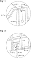
Fig. 11 is an enlarged view showing the proximity of a through hole extending through an upper end of a base ofFig. 9 . -
Fig. 12 is an enlarged view showing the proximity of a through hole extending through a lower end of the base ofFig. 9 . - One embodiment of a seat support device will now be described.
- As shown in
Fig. 1 , avehicle seat 1 includes a seat cushion 2, aseat back 3 arranged at a rear end of the seat cushion 2 in an inclinable manner, and a head rest 4 arranged at an upper end of theseat back 3. A plurality of seat support devices 10 (10A, 10B) are arranged in the seat back 3. - Further, the
seat back 3 includes seat backside portions shoulder portion 3c, each having a frontward bulging support shape. This ensures a satisfactory seating position for the vehicle occupant who is seated on theseat 1 and kept at the seating position. - Each of the support devices 10 (10A, 10B) includes an airbag 5 (5a to 5c) arranged inside the seat back 3. An air supply/discharge device (not shown) charges the
airbag 5 with air and discharges air from theairbags 5 to expand and contract theairbags 5. This allows the seat support devices 10 (10A, 10B) to change the support shapes set for the seat backside portions shoulder portion 3c. - In detail, as shown in
Figs. 2 to 4 , theseat support devices 10A arranged inside the seat backside portions base 21 and apaddle 22. Thebase 21 is fixed to a frame 11 of theseat back 3. Thepaddle 22 is movable toward and away from thebase 21. Thebase 21 includes a front surface Sa opposing thepaddle 22 and a rear surface Sb located at a side opposite to the front surface Sa. - In the present embodiment, the left and right
seat support devices 10A arranged in the seat backside portions airbags 5 and differ only in that they are located at left and right sides. Thus, to facilitate understanding,Figs. 2 and3 show only the seat backside portion 3a of theseat back 3. - The
base 21 includes aflat base body 21 a andribs 23 arranged on one surface (rib formation surface 21s) of thebase body 21a. Thebase 21 is fixed to the frame 11 of theseat back 3 with the rear surface Sb of thebase 21, on which theribs 23 are arranged, facing a back surface (upper side inFigs. 2 and3 ) of the seat back 3. - The
paddle 22 has a flat shape and is located at a position opposing thebase body 21a. Two side ends of thepaddle 22 each include a flanged foldedportion 24 extending toward thebase body 21a. Eachseat support device 10A holds the corresponding airbag 5 (5a, 5b) by holding theairbag 5 between thepaddle 22 and thebase body 21a. - When the
airbag 5 is deployed, theairbag 5 pushes thepaddle 22 and moves thepaddle 22 away from thebase body 21a, which opposes thepaddle 22. Thus, when thepaddle 22 pushes aseat pad 30 arranged inside the seat back 3, a pushed portion of theseat pad 30 moves together with a covering 31 of the seat back 3. Theseat pad 30 is formed from, for example, a sponge cushion material. In this manner, theseat support devices 10A bulge the seat backside portions Figs. 2 and3 ) to change the support shapes of the seat backside portions - A
support surface 3s of each of the seat backside portions seat 1 from the outer side in the widthwise direction of the seat (right side inFigs. 2 and3 ). Further, thebase body 21a and thepaddle 22 are arranged inside the seat back 3 substantially parallel to thesupport surface 3s. A portion of each of the seat pads 30 (30a, 30b) arranged at the corresponding seat backside portion paddle 22 when theairbag 5 deploys is in close contact with thepaddle 22. This moves thesupport surface 3s of each of the seat backside portions seat 1 and the inner side in the widthwise direction of the seat (left side inFigs. 2 and3 ). - Further, as shown in
Figs. 4 to 6 , theseat support device 10A includes acable 40 that connects thebase 21 and thepaddle 22. More specifically, thecable 40 includes afirst end 40a engaged with thebase 21 and asecond end 40b engaged with thepaddle 22. This limits the movement range of thepaddle 22 that moves away from thebase 21, that is, the movement range of thepaddle 22 in the direction in which theairbag 5 deploys. - In detail, the
first end 40a of thecable 40 includes a sphericalfirst terminal member 45a. Further, thesecond end 40b of thecable 40 includes a cylindricalsecond terminal member 45b. Thepaddle 22 includes anengagement portion 46 with a slit-shaped insertion hole 46a. Thesecond terminal member 45b is inserted into the insertion hole 46a along the slit shape and attached to theengagement portion 46.
This engages thesecond end 40b with thepaddle 22. - In addition, the
cable 40 is extended from the front side of the base 21 to the rear side of thebase 21. Thefirst end 40a of thecable 40 is engaged with the base 21 at the rear side of thebase 21. - The
base 21 includes aguide 48 arranged on an upper end of thebase body 21a. Theguide 48 includes a guide groove, into which thecable 40 is fitted, and is formed from a soft resin material having a high sliding property. Thecable 40 extends along theguide 48 downwardly from the upper end of thebase body 21a and along therib formation surface 21s of thebase body 21a. - Further, the
seat support device 10A includes acompression coil spring 50 arranged on the rear side of thebase 21 and extending in the vertical direction of thebase body 21a. More specifically, thecompression coil spring 50 is arranged below theguide 48 between twovertical ribs rib formation surface 21s. Apressing plate 51 is arranged between thevertical ribs compression coil spring 50 is arranged between thepressing plate 51 and therib formation surface 21s. Thecable 40 is inserted through thecompression coil spring 50 and extended along therib formation surface 21s. - The
cable 40 includes a disk-shaped abutment member 55 (washer) arranged adjacent to thefirst terminal member 45a. Thecable 40 extends through theabutment member 55 in a thickness-wise direction of theabutment member 55. Further, ahorizontal rib 23c extends from therib formation surface 21s of thebase body 21 a. Thehorizontal rib 23c intersects the twovertical ribs compression coil spring 50. Thehorizontal rib 23c is located adjacent to theguide 48 in the proximity of the upper end of thebase body 21a. Thecompression coil spring 50 is held on therib formation surface 21s between thehorizontal rib 23c and theabutment member 55. - As shown in
Fig. 5 , thecable 40 is engaged with the base 21 on the rear surface Sb of the base 21 with theabutment member 55 at thefirst end 40a receiving a lower end of thecompression coil spring 50. This forms an engagement mechanism 61 of thecable 40 on the rear surface Sb of thebase 21. - As shown in
Fig. 6 , when deployment of theairbag 5 moves thepaddle 22 away from thebase 21, thecompression coil spring 50, which is held between theabutment member 55 serving as a first abutment portion and thehorizontal rib 23c serving as a second abutment portion, is further compressed. - More specifically, a stretching mechanism 62 that pulls the
first end 40a of thecable 40 with the elastic force (elastic restoration force) of thecompression coil spring 50 is formed on the rear surface Sb of thebase 21. When theairbag 5 contracts, the stretching mechanism 62 returns thepaddle 22 that has moved away from the base 21 to the initial position (position shown inFig. 5 ). As a result, the support shapes of the seat backside portions - Further, when the
compression coil spring 50 held between theabutment member 55 and thehorizontal rib 23c reaches a compression limit, theseat support device 10A of the present embodiment restricts movement that separates thepaddle 22 from thebase 21. This limits excessive movement of thepaddle 22 and the seat backside portions - As shown in
Figs. 7 and 8 , in the same manner as theseat support devices 10A arranged inside the seat backside portions seat support device 10B arranged inside the seat backshoulder portion 3c includes abase 71 and apaddle 72. More specifically, thebase 71 of theseat support device 10B includes aflat base body 71a and theribs 23 arranged on arib formation surface 71s (right side, back surface of seat back 3 inFigs. 7 and 8 ) of thebase body 71a. Thepaddle 72 includes aflat plate 72a, which is opposed to thebase body 71a, and is movable toward and away from thebase 71. Theseat support device 10B holds the airbag 5 (5c) between thebase body 71 a and theflat plate 72a of thepaddle 72. - More specifically, the
seat support device 10B is also configured so that thepaddle 72, which is pushed by theairbag 5 when theairbag 5 is deployed, moves away from thebase body 71a, which opposes thepaddle 22. This changes the support shape of the seat backshoulder portion 3c that bulges toward the front of theseat 1. - The
base body 71a and theflat plate 72a of thepaddle 72 are arranged inside the seat back 3 substantially parallel to thesupport surface 3s of the seat backshoulder portion 3c. A portion of the seat pad 30 (30c) arranged in the seat backshoulder portion 3c that is pushed by thepaddle 72 when theairbag 5 deploys is in close contact with thepaddle 22. This moves thesupport surface 3s of the seat backshoulder portion 3c toward the front of theseat 1. - Further, the
seat support device 10B includes a plurality ofcables 80 that connect thebase 71 and thepaddle 72. More specifically, theseat support device 10B includes afirst cable 81 having afirst end 80a engaged with an upper end of thebase body 71a and asecond cable 82 having afirst end 80a engaged with a lower end of thebase body 71a. Thefirst cable 81 and thesecond cable 82 limit the movement range of thepaddle 72 that moves away from the base 71 at two positions, namely, the upper end and the lower end of thebase 71. - In detail, as shown in
Figs. 7 to 10 , each cable 80 (81, 82) includes thefirst end 80a and asecond end 80b. Eachfirst end 80a includes a sphericalfirst terminal member 85a, and eachsecond end 80b includes a sphericalsecond terminal member 85b. Further, thepaddle 72 includesengagement portions paddle 72 opposing the upper end and the lower end of thebase 71. Theengagement portions cable 80 with thepaddle 22 by holding thesecond terminal member 85b in the same manner as theengagement portion 46 of thepaddle 22 of theseat support device 10A. Throughholes base body 71a at positions respectively opposing theengagement portions holes first cable 81 and thesecond cable 82 are respectively inserted through the throughholes base 71. - More specifically, as shown in
Fig. 11 , the through hole 88 (groove) is slit-shaped and opens in the upper end of thebase body 71a. Thefirst cable 81 is arranged in the throughhole 88 from the upper end of thebase body 71a. - Further, as shown in
Fig. 12 , the throughhole 89 extending through the lower end of thebase body 71a is shaped to allow insertion of thefirst terminal member 85a of the cable 80 (82) from the front side of thebase 71. The throughhole 89 is circular and has a larger diameter than thefirst terminal member 85a. Agrooved recess 89a extends downwardly from the throughhole 89. Thesecond cable 82 inserted through the throughhole 89 is positioned in therecess 89a by the weight of thefirst terminal member 85a. - The
first terminal member 85a of eachcable 80 is arranged at the rear side of thebase 71. Each of the throughholes cable 80 is inserted, has a hole shape that restricts passage of thefirst terminal member 85a from the rear side of the base 71 toward the front side of thebase 71. - More specifically, as shown in
Fig. 11 , the width of the groove of the throughhole 88 extending through the upper end of thebase body 71a is narrower than the diameter of thefirst terminal member 85a of thefirst cable 81. As shown inFig. 12 , the width of the groove of therecess 89a of the throughhole 89 extending through the lower end of thebase body 71a is narrower than the diameter of thefirst terminal member 85a of thesecond cable 82. - In other words, the through
holes rib formation surface 71s of thebase body 71a as thefirst terminal member 85a of eachcable 80 moves from the rear side of the base 71 toward the front side of thebase 71. This engages thefirst end 80a of eachcable 80 with the base 71 on the rear surface Sb of thebase 71. - More specifically, as shown in
Figs. 7 and9 , in a state in which theairbag 5 is contracted and thebase body 71a is thus located proximate to theflat plate 72a of thepaddle 72, the weight of thefirst terminal member 85a pulls thefirst end 80a of eachcable 80 toward the rear side of thebase 71. As shown inFigs. 8 and10 , when deployment of theairbag 5 moves theflat plate 72a of thepaddle 72 away from thebase body 71a, eachcable 80 is pulled out toward the front side of the base 71 through the corresponding throughhole first terminal member 85a of eachcable 80 abuts against and engages with therib formation surface 71s of thebase body 71a, eachcable 80 is fully stretched. This restricts movement that separates thepaddle 72 from thebase 71 and limits excessive movement of thepaddle 72 and the seat backshoulder portion 3c, which form a movable unit. - Further, as shown in
Fig. 8 , the cables 80 (81, 82) have different stretched lengths L1 and L2. That is, thefirst cable 81 and thesecond cable 82 are set to have different maximum lengths over which they are pulled out toward the front side of the base 71 when thepaddle 72 is moved away from thebase 71. More specifically, in the present embodiment, the stretched length L1 of thefirst cable 81 is greater than the stretched length L2 of the second cable 82 (L1 > L2). Thefirst cable 81 and thesecond cable 82 restrict movement that separates thepaddle 72 from thebase 71 and set the position of thepaddle 72 when the airbag 5 (5c) is deployed to full extent. - More specifically, the
seat support device 10B of the present embodiment is configured so that when theairbag 5 is deployed, the upper portion of thepaddle 72 projects further toward the front of theseat 1 than the lower portion of thepaddle 72 so that thepaddle 72 is inclined frontward. Thus, the seat backshoulder portion 3c in which the seat pad 30 (30c) is pushed by thepaddle 72 is deformed to a support shape in which the upper portion of the seat backshoulder portion 3c bulges further toward the front of theseat 1 than the lower portion of the seat backshoulder portion 3c. - The present embodiment has the advantages described below.
- (1) The seat support device 10 (10A, 10B) includes the base (21, 71) fixed to the frame 11 of the seat back 3 and the paddle (22, 72) movable toward and away from the base (21, 71). Further, the
seat support device 10 holds the airbag 5 (5a to 5c) between the base (21, 71) and the paddle (22, 72). Theseat support device 10 includes the cable (40, 80) including the first end (40a, 80a) engaged with the base (21, 71) and the second end (40b, 80b) engaged with the paddle (22, 72). - In the above structure, connecting of the base (21, 71) and the paddle (22, 72) with the cable (40, 80) restricts the movement range of the paddle (22, 72) that moves away from the base (21, 71). Further, it is desirable that the
seat support device 10, which is arranged inside the seat back 3, be further compact. In this regard, the cable (40, 80) is advantageous in that there is no need for a large space regardless of whether the paddle (22, 72) moves toward or away from the base (21, 71). This ensures high reliability of theseat support device 10 with a compact and simple structure. - (2) In the
seat support device 10A arranged inside the seat backside portions cable 40 is extended from the front side of the base 21 opposing thepaddle 22 toward the rear side of thebase 21. Further, thefirst end 40a of thecable 40 includes the abutment member 55 (washer) serving as the first abutment portion, and the rear surface Sb of thebase 21, i.e. therib formation surface 21s of thebase body 21a, includes thehorizontal rib 23 serving as the second abutment portion. Thecompression coil spring 50, serving as a compression coil member, is held on the rear side of the base 21 in a state held and compressed between theabutment member 55 and thehorizontal rib 23c. - In the above structure, the engagement mechanism 61 that engages the
first end 40a of thecable 40 and the stretching mechanism 62 that pulls thefirst end 40a of thecable 40 are formed on the rear surface Sb of the base 21 in a compact manner. This allows for high reliability of the engagement mechanism 61 and the stretching mechanism 62 with a compact and simple structure. - More specifically, when the
first end 40a of thecable 40 is pulled with the elastic force (elastic restoration force) of thecompression coil spring 50, thepaddle 22 that has moved away from the base 21 can smoothly return to the initial position when theairbag 5 contracts. Further, when thecompression coil spring 50 held between theabutment member 55 of thefirst end 40a of thecable 40 and thehorizontal rib 23c of thebase 21 reaches a compression limit, movement of thepaddle 22 from thebase 21 is restricted. The arrangement of thecompression coil spring 50, theabutment member 55, and thehorizontal rib 23c on the rear side of thebase 21 allows theseat support device 10A to be reduced in size. This increases the degree of freedom for the location of theseat support device 10A. Thus, the space in the seat backs 3 can be effectively used. - (3) The
base 21 includes theguide 48 arranged at the upper end of thebase body 21a. Theguide 48 guides thecable 40 so that it extends from the front side of the base 21 toward the rear side of thebase 21. - The above structure smoothens the movement of the
cable 40 that is pulled out from the rear side of the base 21 toward the front side of the base 21 when thepaddle 22 moves away from thebase 21 and smoothens the movement of thecable 40 pulled back toward the rear side of the base 21 from the front side of the base 21 when thepaddle 22 moves toward thebase 21. This reduces wear of thecable 40 and the possibility of thecable 40 being tangled. Thus, high reliability is ensured. This further increases the degree of design freedom for the engagement mechanism 61 and the stretching mechanism 62 on the rear surface Sb of thebase 21. - (4) The through
holes base body 71a) in theseat support device 10B arranged inside the seat backshoulder portion 3c. Thefirst end 80a of thefirst cable 81 is inserted through the throughhole 88, and thefirst end 80a of thesecond cable 82 is inserted through the throughhole 89. Thefirst end 80a of eachcable 80 includes thefirst terminal member 85a that cannot pass through the corresponding throughhole base 71. - In the above structure, when each
cable 80 is fully stretched, thefirst terminal member 85a is engaged with the rear surface Sb of thebase 71. This further ensures restriction of movement of thepaddle 72 away from the base 71 with a compact and simple structure. When thebase 71 and thepaddle 72 are proximate to each other, eachcable 80 is pulled toward the rear side of the base 71 by the weight of thefirst terminal member 85a. This reduces the possibility of eachcable 80 being tangled. As a result, higher reliability is ensured. - (5) The
seat support device 10B includes thefirst cable 81 including thefirst end 80a engaged with the upper end of thebase body 71a and thesecond cable 82 including thefirst end 80a engaged with the lower end of thebase body 71a. The stretched length L1 of thefirst cable 81 is greater than the stretched length L2 of the second cable 82 (L1 > L2). - In the above structure, when the
airbag 5 deploys, thepaddle 72 is inclined frontward so that the upper portion of thepaddle 72 projects further toward the front of theseat 1 than the lower portion of thepaddle 72. - The above embodiment may be modified as described below.
- In the above embodiment, the
seat support devices 10A that include thecompression coil spring 50 are arranged inside the seat backside portions seat support device 10B that does not include thecompression coil spring 50 is arranged inside the seat backshoulder portion 3c. Instead, theseat support device 10B that does not include thecompression coil spring 50 may be arranged inside the seat backside portions seat support device 10A that includes thecompression coil spring 50 may be arranged inside the seat backshoulder portion 3c. Further, any one of theseat support devices side portions shoulder portion 3c. - In the
seat support device 10B that does not include thecompression coil spring 50, thefirst terminal member 85a on thefirst end 80a of thecable 80 can be used as a weight to apply pulling force that is the same as that of the stretching mechanism 62 of theseat support device 10A that uses thecompression coil spring 50. - In the above embodiment, the seat support devices 10 (10A, 10B) are arranged inside the seat back
side portions shoulder portion 3c. However, theseat support devices 10 do not have to be arranged in this manner. For example, theseat support devices 10 may be arranged inside the seat cushion 2 and the head rest 4. When theseat support devices 10 are arranged inside the seat cushion 2, theseat support devices 10 are arranged in, for example, seat cushion sides 2a and 2b (refer toFig. 1 ). In addition, theseat support devices 10 may be arranged in portions other than the seat backside portions shoulder portion 3c of the seat back 3. Further, theseat support device 10 may be arranged in an additional component of the seat such as an ottoman. Additionally, the total number of theseat support devices 10 and the combination of arrangement of theseat support devices 10 may be changed. - In the above embodiment, in each
seat support device 10A, the engagement mechanism 61 and the stretching mechanism 62 are formed by thecompression coil spring 50, which serves as a compression spring member, and the first abutment portion (abutment member 55) and the second abutment portion (horizontal rib 23c), which hold thecompression coil spring 50 in the vertical direction. Instead, as long as the engagement mechanism 61 and the stretching mechanism 62 are arranged on the rear side of thebase 21, the structures of the engagement mechanism 61 and the stretching mechanism 62 may be changed. - For example, the arrangement of the
compression coil spring 50 and the second abutment portion may be changed. Further, a compression spring member other than thecompression coil spring 50 may be held between the first abutment portion and the second abutment portion. A plurality of compression coil springs may be used. Additionally, the engagement mechanism 61 and the stretching mechanism 62 may be independent from each other. A tensile spring member or other biasing members may be used for the stretching mechanism 62. - In the above embodiment, in each
seat support device 10A, thecable 40 is extended from the front side of the base 21 to the rear side of the base 21 through theguide 48 on the upper end of thebase body 21a. Instead, thecable 40 may be extended from the front side of the base 21 to the rear side of the base 21 through another portion such as the lower end or a through hole of thebase body 21a. In this case, theguide 48 does not need to be located where thecable 40 is extended. - Further, in the
seat support device 10B, each cable 80 (81, 82) is inserted through the corresponding throughhole base body 71 a. Thefirst terminal member 85a abuts against thebase body 71a from the rear side of thebase 71 and engages thebase 71. Instead, the structure of thefirst end 80a of eachcable 80 that engages the base 71 may be changed. For example, eachcable 80 may be loose on the front side or the rear side of thebase 71. Further, a structure that engages thefirst end 80a of eachcable 80 on the front side of thebase 71 and a structure that arranges a tensile spring member between the base 71 and thepaddle 72 may also be employed. - In the above embodiment, the
seat support device 10B includes the two cables 80 (81, 82) having different stretched lengths (L1, L2). Instead, theseat support device 10B may include three ormore cables 80 having different stretched lengths. This allows thepaddle 72 to be set to any position when theairbag 5 is deployed. Theseat support device 10B may include a plurality ofcables 80 having the same stretched length. All thecables 80 may have the same stretched lengths.
Claims (6)
- A seat support device comprising:a base fixed to an inner side of a seat;a paddle movable toward and away from the base;an airbag arranged between the base and the paddle, wherein the airbag pushes a seat pad of the seat with the paddle when deployed; anda cable including a first end engaged with the base and a second end engaged with the paddle.
- The seat support device according to claim 1, wherein
the cable is extended from a front side of the base opposing the paddle toward a rear side of the base, and
the rear side of the base includes an engagement mechanism that engages the first end of the cable and a stretching mechanism that pulls the first end of the cable. - The seat support device according to claim 2, comprising:a first abutment portion arranged on the first end of the cable;a second abutment portion arranged on a rear surface of the base; anda compression spring member held between the first abutment portion and the second abutment portion.
- The seat support device according to claim 2 or 3, wherein the base includes a guide that guides the cable from the front side of the base toward the rear side of the base.
- The seat support device according to any one of claims 1 to 4, wherein
the base includes a through hole through which a front surface of the base opposing the paddle is in communication with a rear surface of the base,
the cable is inserted through the through hole, and
the first end of the cable includes a terminal member that cannot pass through the through hole from a rear side of the base toward a front side of the base. - The seat support device according to any one of claims 1 to 5, comprising a plurality of cables having different stretched lengths.
Applications Claiming Priority (2)
| Application Number | Priority Date | Filing Date | Title |
|---|---|---|---|
| JP2015076012A JP2016196202A (en) | 2015-04-02 | 2015-04-02 | Seat support device |
| PCT/JP2016/060438 WO2016159105A1 (en) | 2015-04-02 | 2016-03-30 | Seat support apparatus |
Publications (2)
| Publication Number | Publication Date |
|---|---|
| EP3279028A1 true EP3279028A1 (en) | 2018-02-07 |
| EP3279028A4 EP3279028A4 (en) | 2018-03-21 |
Family
ID=57005089
Family Applications (1)
| Application Number | Title | Priority Date | Filing Date |
|---|---|---|---|
| EP16772986.2A Withdrawn EP3279028A4 (en) | 2015-04-02 | 2016-03-30 | Seat support apparatus |
Country Status (5)
| Country | Link |
|---|---|
| US (1) | US20180079336A1 (en) |
| EP (1) | EP3279028A4 (en) |
| JP (1) | JP2016196202A (en) |
| CN (1) | CN107406013A (en) |
| WO (1) | WO2016159105A1 (en) |
Families Citing this family (2)
| Publication number | Priority date | Publication date | Assignee | Title |
|---|---|---|---|---|
| CN115139882A (en) | 2021-03-29 | 2022-10-04 | 本田技研工业株式会社 | Seat adjusting device |
| JP7382369B2 (en) | 2021-08-06 | 2023-11-16 | 本田技研工業株式会社 | seat structure |
Family Cites Families (8)
| Publication number | Priority date | Publication date | Assignee | Title |
|---|---|---|---|---|
| JPS6127483Y2 (en) * | 1980-11-12 | 1986-08-15 | ||
| DE4106863C2 (en) * | 1991-03-05 | 1994-10-20 | Daimler Benz Ag | Motor vehicle seat |
| DE10028341B4 (en) * | 2000-06-08 | 2005-11-10 | Keiper Gmbh & Co.Kg | Vehicle seat with entry and exit help |
| JP2008143306A (en) * | 2006-12-08 | 2008-06-26 | Toyoda Gosei Co Ltd | Vehicle seat |
| US8602449B2 (en) * | 2009-05-11 | 2013-12-10 | Toyota Jidosha Kabushiki Kaisha | Vehicle seat |
| JP2012106601A (en) * | 2010-11-17 | 2012-06-07 | Toyota Boshoku Corp | Vehicle seat |
| JP6140499B2 (en) * | 2013-03-27 | 2017-05-31 | テイ・エス テック株式会社 | Vehicle drive mechanism |
| JP6070431B2 (en) * | 2013-06-19 | 2017-02-01 | トヨタ紡織株式会社 | Vehicle seat |
-
2015
- 2015-04-02 JP JP2015076012A patent/JP2016196202A/en not_active Withdrawn
-
2016
- 2016-03-30 CN CN201680016084.5A patent/CN107406013A/en active Pending
- 2016-03-30 US US15/562,135 patent/US20180079336A1/en not_active Abandoned
- 2016-03-30 EP EP16772986.2A patent/EP3279028A4/en not_active Withdrawn
- 2016-03-30 WO PCT/JP2016/060438 patent/WO2016159105A1/en not_active Ceased
Also Published As
| Publication number | Publication date |
|---|---|
| EP3279028A4 (en) | 2018-03-21 |
| CN107406013A (en) | 2017-11-28 |
| WO2016159105A1 (en) | 2016-10-06 |
| JP2016196202A (en) | 2016-11-24 |
| US20180079336A1 (en) | 2018-03-22 |
Similar Documents
| Publication | Publication Date | Title |
|---|---|---|
| US11021129B2 (en) | Occupant restraint device | |
| JP6839775B2 (en) | Crew restraint device | |
| CN108016397B (en) | Self-standing central side airbag | |
| US9238422B2 (en) | Vehicle seat sliding apparatus | |
| JP4834735B2 (en) | Retractor | |
| CN104210389B (en) | The wire structures of electric wire | |
| CN107054177B (en) | Armrest device | |
| CN104163123B (en) | Seat | |
| CN116261537B (en) | Safety airbag devices for vehicle seats and vehicle seats equipped with airbags | |
| CN105593058A (en) | seat structure | |
| EP3279028A1 (en) | Seat support apparatus | |
| CN102001298B (en) | Fold and dive seat | |
| JP6897472B2 (en) | Vehicle seat belt device | |
| DE102014223955A1 (en) | Seat assembly with a reference arrangement | |
| EP2492158A1 (en) | Seat belt assembly | |
| US9027994B2 (en) | Locking structure for skin terminals of vehicle seat and vehicle seat provided with locking structure | |
| CN113167088B (en) | Arrangement for guiding a movable furniture part | |
| GB2376216A (en) | A vehicle seat belt retainer and seat | |
| CN105703286B (en) | cable anchoring device | |
| CN108068675B (en) | Use of plastic hose as spring and fitting | |
| KR101836794B1 (en) | Guiding device for stay rod for headrest of seat | |
| CN109383332B (en) | Vehicle seat | |
| KR20220135478A (en) | Guide device for deploying the roof airbag | |
| CN110920473B (en) | Covering device for a vehicle seat | |
| US10641309B2 (en) | Air bag apparatus |
Legal Events
| Date | Code | Title | Description |
|---|---|---|---|
| PUAI | Public reference made under article 153(3) epc to a published international application that has entered the european phase |
Free format text: ORIGINAL CODE: 0009012 |
|
| 17P | Request for examination filed |
Effective date: 20170926 |
|
| AK | Designated contracting states |
Kind code of ref document: A1 Designated state(s): AL AT BE BG CH CY CZ DE DK EE ES FI FR GB GR HR HU IE IS IT LI LT LU LV MC MK MT NL NO PL PT RO RS SE SI SK SM TR |
|
| AX | Request for extension of the european patent |
Extension state: BA ME |
|
| A4 | Supplementary search report drawn up and despatched |
Effective date: 20180221 |
|
| RIC1 | Information provided on ipc code assigned before grant |
Ipc: B60N 2/02 20060101ALI20180215BHEP Ipc: A47C 7/46 20060101ALI20180215BHEP Ipc: B60N 2/22 20060101AFI20180215BHEP Ipc: A47C 7/14 20060101ALI20180215BHEP |
|
| DAV | Request for validation of the european patent (deleted) | ||
| DAX | Request for extension of the european patent (deleted) | ||
| STAA | Information on the status of an ep patent application or granted ep patent |
Free format text: STATUS: THE APPLICATION IS DEEMED TO BE WITHDRAWN |
|
| 18D | Application deemed to be withdrawn |
Effective date: 20180920 |