EP3278963A1 - Structural body production method and structural body - Google Patents
Structural body production method and structural body Download PDFInfo
- Publication number
- EP3278963A1 EP3278963A1 EP16771986.3A EP16771986A EP3278963A1 EP 3278963 A1 EP3278963 A1 EP 3278963A1 EP 16771986 A EP16771986 A EP 16771986A EP 3278963 A1 EP3278963 A1 EP 3278963A1
- Authority
- EP
- European Patent Office
- Prior art keywords
- fiber composite
- composite material
- carbon fiber
- polishing
- layer
- Prior art date
- Legal status (The legal status is an assumption and is not a legal conclusion. Google has not performed a legal analysis and makes no representation as to the accuracy of the status listed.)
- Withdrawn
Links
Images



Classifications
-
- B—PERFORMING OPERATIONS; TRANSPORTING
- B32—LAYERED PRODUCTS
- B32B—LAYERED PRODUCTS, i.e. PRODUCTS BUILT-UP OF STRATA OF FLAT OR NON-FLAT, e.g. CELLULAR OR HONEYCOMB, FORM
- B32B5/00—Layered products characterised by the non- homogeneity or physical structure, i.e. comprising a fibrous, filamentary, particulate or foam layer; Layered products characterised by having a layer differing constitutionally or physically in different parts
- B32B5/22—Layered products characterised by the non- homogeneity or physical structure, i.e. comprising a fibrous, filamentary, particulate or foam layer; Layered products characterised by having a layer differing constitutionally or physically in different parts characterised by the presence of two or more layers which are next to each other and are fibrous, filamentary, formed of particles or foamed
- B32B5/24—Layered products characterised by the non- homogeneity or physical structure, i.e. comprising a fibrous, filamentary, particulate or foam layer; Layered products characterised by having a layer differing constitutionally or physically in different parts characterised by the presence of two or more layers which are next to each other and are fibrous, filamentary, formed of particles or foamed one layer being a fibrous or filamentary layer
- B32B5/26—Layered products characterised by the non- homogeneity or physical structure, i.e. comprising a fibrous, filamentary, particulate or foam layer; Layered products characterised by having a layer differing constitutionally or physically in different parts characterised by the presence of two or more layers which are next to each other and are fibrous, filamentary, formed of particles or foamed one layer being a fibrous or filamentary layer another layer next to it also being fibrous or filamentary
-
- B—PERFORMING OPERATIONS; TRANSPORTING
- B24—GRINDING; POLISHING
- B24B—MACHINES, DEVICES, OR PROCESSES FOR GRINDING OR POLISHING; DRESSING OR CONDITIONING OF ABRADING SURFACES; FEEDING OF GRINDING, POLISHING, OR LAPPING AGENTS
- B24B1/00—Processes of grinding or polishing; Use of auxiliary equipment in connection with such processes
-
- B—PERFORMING OPERATIONS; TRANSPORTING
- B24—GRINDING; POLISHING
- B24B—MACHINES, DEVICES, OR PROCESSES FOR GRINDING OR POLISHING; DRESSING OR CONDITIONING OF ABRADING SURFACES; FEEDING OF GRINDING, POLISHING, OR LAPPING AGENTS
- B24B7/00—Machines or devices designed for grinding plane surfaces on work, including polishing plane glass surfaces; Accessories therefor
- B24B7/20—Machines or devices designed for grinding plane surfaces on work, including polishing plane glass surfaces; Accessories therefor characterised by a special design with respect to properties of the material of non-metallic articles to be ground
- B24B7/30—Machines or devices designed for grinding plane surfaces on work, including polishing plane glass surfaces; Accessories therefor characterised by a special design with respect to properties of the material of non-metallic articles to be ground for grinding plastics
-
- B—PERFORMING OPERATIONS; TRANSPORTING
- B29—WORKING OF PLASTICS; WORKING OF SUBSTANCES IN A PLASTIC STATE IN GENERAL
- B29C—SHAPING OR JOINING OF PLASTICS; SHAPING OF MATERIAL IN A PLASTIC STATE, NOT OTHERWISE PROVIDED FOR; AFTER-TREATMENT OF THE SHAPED PRODUCTS, e.g. REPAIRING
- B29C43/00—Compression moulding, i.e. applying external pressure to flow the moulding material; Apparatus therefor
- B29C43/02—Compression moulding, i.e. applying external pressure to flow the moulding material; Apparatus therefor of articles of definite length, i.e. discrete articles
- B29C43/20—Making multilayered or multicoloured articles
-
- B—PERFORMING OPERATIONS; TRANSPORTING
- B29—WORKING OF PLASTICS; WORKING OF SUBSTANCES IN A PLASTIC STATE IN GENERAL
- B29C—SHAPING OR JOINING OF PLASTICS; SHAPING OF MATERIAL IN A PLASTIC STATE, NOT OTHERWISE PROVIDED FOR; AFTER-TREATMENT OF THE SHAPED PRODUCTS, e.g. REPAIRING
- B29C65/00—Joining or sealing of preformed parts, e.g. welding of plastics materials; Apparatus therefor
- B29C65/48—Joining or sealing of preformed parts, e.g. welding of plastics materials; Apparatus therefor using adhesives, i.e. using supplementary joining material; solvent bonding
-
- B—PERFORMING OPERATIONS; TRANSPORTING
- B29—WORKING OF PLASTICS; WORKING OF SUBSTANCES IN A PLASTIC STATE IN GENERAL
- B29C—SHAPING OR JOINING OF PLASTICS; SHAPING OF MATERIAL IN A PLASTIC STATE, NOT OTHERWISE PROVIDED FOR; AFTER-TREATMENT OF THE SHAPED PRODUCTS, e.g. REPAIRING
- B29C66/00—General aspects of processes or apparatus for joining preformed parts
- B29C66/01—General aspects dealing with the joint area or with the area to be joined
- B29C66/02—Preparation of the material, in the area to be joined, prior to joining or welding
- B29C66/022—Mechanical pre-treatments, e.g. reshaping
- B29C66/0224—Mechanical pre-treatments, e.g. reshaping with removal of material
- B29C66/02245—Abrading, e.g. grinding, sanding, sandblasting or scraping
-
- B—PERFORMING OPERATIONS; TRANSPORTING
- B29—WORKING OF PLASTICS; WORKING OF SUBSTANCES IN A PLASTIC STATE IN GENERAL
- B29C—SHAPING OR JOINING OF PLASTICS; SHAPING OF MATERIAL IN A PLASTIC STATE, NOT OTHERWISE PROVIDED FOR; AFTER-TREATMENT OF THE SHAPED PRODUCTS, e.g. REPAIRING
- B29C66/00—General aspects of processes or apparatus for joining preformed parts
- B29C66/01—General aspects dealing with the joint area or with the area to be joined
- B29C66/05—Particular design of joint configurations
- B29C66/10—Particular design of joint configurations particular design of the joint cross-sections
- B29C66/11—Joint cross-sections comprising a single joint-segment, i.e. one of the parts to be joined comprising a single joint-segment in the joint cross-section
- B29C66/112—Single lapped joints
-
- B—PERFORMING OPERATIONS; TRANSPORTING
- B29—WORKING OF PLASTICS; WORKING OF SUBSTANCES IN A PLASTIC STATE IN GENERAL
- B29C—SHAPING OR JOINING OF PLASTICS; SHAPING OF MATERIAL IN A PLASTIC STATE, NOT OTHERWISE PROVIDED FOR; AFTER-TREATMENT OF THE SHAPED PRODUCTS, e.g. REPAIRING
- B29C66/00—General aspects of processes or apparatus for joining preformed parts
- B29C66/01—General aspects dealing with the joint area or with the area to be joined
- B29C66/05—Particular design of joint configurations
- B29C66/10—Particular design of joint configurations particular design of the joint cross-sections
- B29C66/13—Single flanged joints; Fin-type joints; Single hem joints; Edge joints; Interpenetrating fingered joints; Other specific particular designs of joint cross-sections not provided for in groups B29C66/11 - B29C66/12
- B29C66/131—Single flanged joints, i.e. one of the parts to be joined being rigid and flanged in the joint area
-
- B—PERFORMING OPERATIONS; TRANSPORTING
- B29—WORKING OF PLASTICS; WORKING OF SUBSTANCES IN A PLASTIC STATE IN GENERAL
- B29C—SHAPING OR JOINING OF PLASTICS; SHAPING OF MATERIAL IN A PLASTIC STATE, NOT OTHERWISE PROVIDED FOR; AFTER-TREATMENT OF THE SHAPED PRODUCTS, e.g. REPAIRING
- B29C66/00—General aspects of processes or apparatus for joining preformed parts
- B29C66/40—General aspects of joining substantially flat articles, e.g. plates, sheets or web-like materials; Making flat seams in tubular or hollow articles; Joining single elements to substantially flat surfaces
- B29C66/47—Joining single elements to sheets, plates or other substantially flat surfaces
- B29C66/474—Joining single elements to sheets, plates or other substantially flat surfaces said single elements being substantially non-flat
-
- B—PERFORMING OPERATIONS; TRANSPORTING
- B29—WORKING OF PLASTICS; WORKING OF SUBSTANCES IN A PLASTIC STATE IN GENERAL
- B29C—SHAPING OR JOINING OF PLASTICS; SHAPING OF MATERIAL IN A PLASTIC STATE, NOT OTHERWISE PROVIDED FOR; AFTER-TREATMENT OF THE SHAPED PRODUCTS, e.g. REPAIRING
- B29C66/00—General aspects of processes or apparatus for joining preformed parts
- B29C66/50—General aspects of joining tubular articles; General aspects of joining long products, i.e. bars or profiled elements; General aspects of joining single elements to tubular articles, hollow articles or bars; General aspects of joining several hollow-preforms to form hollow or tubular articles
- B29C66/51—Joining tubular articles, profiled elements or bars; Joining single elements to tubular articles, hollow articles or bars; Joining several hollow-preforms to form hollow or tubular articles
- B29C66/52—Joining tubular articles, bars or profiled elements
- B29C66/524—Joining profiled elements
-
- B—PERFORMING OPERATIONS; TRANSPORTING
- B29—WORKING OF PLASTICS; WORKING OF SUBSTANCES IN A PLASTIC STATE IN GENERAL
- B29C—SHAPING OR JOINING OF PLASTICS; SHAPING OF MATERIAL IN A PLASTIC STATE, NOT OTHERWISE PROVIDED FOR; AFTER-TREATMENT OF THE SHAPED PRODUCTS, e.g. REPAIRING
- B29C66/00—General aspects of processes or apparatus for joining preformed parts
- B29C66/70—General aspects of processes or apparatus for joining preformed parts characterised by the composition, physical properties or the structure of the material of the parts to be joined; Joining with non-plastics material
- B29C66/72—General aspects of processes or apparatus for joining preformed parts characterised by the composition, physical properties or the structure of the material of the parts to be joined; Joining with non-plastics material characterised by the structure of the material of the parts to be joined
- B29C66/721—Fibre-reinforced materials
- B29C66/7212—Fibre-reinforced materials characterised by the composition of the fibres
-
- B—PERFORMING OPERATIONS; TRANSPORTING
- B29—WORKING OF PLASTICS; WORKING OF SUBSTANCES IN A PLASTIC STATE IN GENERAL
- B29C—SHAPING OR JOINING OF PLASTICS; SHAPING OF MATERIAL IN A PLASTIC STATE, NOT OTHERWISE PROVIDED FOR; AFTER-TREATMENT OF THE SHAPED PRODUCTS, e.g. REPAIRING
- B29C66/00—General aspects of processes or apparatus for joining preformed parts
- B29C66/70—General aspects of processes or apparatus for joining preformed parts characterised by the composition, physical properties or the structure of the material of the parts to be joined; Joining with non-plastics material
- B29C66/72—General aspects of processes or apparatus for joining preformed parts characterised by the composition, physical properties or the structure of the material of the parts to be joined; Joining with non-plastics material characterised by the structure of the material of the parts to be joined
- B29C66/723—General aspects of processes or apparatus for joining preformed parts characterised by the composition, physical properties or the structure of the material of the parts to be joined; Joining with non-plastics material characterised by the structure of the material of the parts to be joined being multi-layered
-
- B—PERFORMING OPERATIONS; TRANSPORTING
- B29—WORKING OF PLASTICS; WORKING OF SUBSTANCES IN A PLASTIC STATE IN GENERAL
- B29C—SHAPING OR JOINING OF PLASTICS; SHAPING OF MATERIAL IN A PLASTIC STATE, NOT OTHERWISE PROVIDED FOR; AFTER-TREATMENT OF THE SHAPED PRODUCTS, e.g. REPAIRING
- B29C66/00—General aspects of processes or apparatus for joining preformed parts
- B29C66/70—General aspects of processes or apparatus for joining preformed parts characterised by the composition, physical properties or the structure of the material of the parts to be joined; Joining with non-plastics material
- B29C66/73—General aspects of processes or apparatus for joining preformed parts characterised by the composition, physical properties or the structure of the material of the parts to be joined; Joining with non-plastics material characterised by the intensive physical properties of the material of the parts to be joined, by the optical properties of the material of the parts to be joined, by the extensive physical properties of the parts to be joined, by the state of the material of the parts to be joined or by the material of the parts to be joined being a thermoplastic or a thermoset
- B29C66/739—General aspects of processes or apparatus for joining preformed parts characterised by the composition, physical properties or the structure of the material of the parts to be joined; Joining with non-plastics material characterised by the intensive physical properties of the material of the parts to be joined, by the optical properties of the material of the parts to be joined, by the extensive physical properties of the parts to be joined, by the state of the material of the parts to be joined or by the material of the parts to be joined being a thermoplastic or a thermoset characterised by the material of the parts to be joined being a thermoplastic or a thermoset
- B29C66/7394—General aspects of processes or apparatus for joining preformed parts characterised by the composition, physical properties or the structure of the material of the parts to be joined; Joining with non-plastics material characterised by the intensive physical properties of the material of the parts to be joined, by the optical properties of the material of the parts to be joined, by the extensive physical properties of the parts to be joined, by the state of the material of the parts to be joined or by the material of the parts to be joined being a thermoplastic or a thermoset characterised by the material of the parts to be joined being a thermoplastic or a thermoset characterised by the material of at least one of the parts being a thermoset
-
- B—PERFORMING OPERATIONS; TRANSPORTING
- B29—WORKING OF PLASTICS; WORKING OF SUBSTANCES IN A PLASTIC STATE IN GENERAL
- B29C—SHAPING OR JOINING OF PLASTICS; SHAPING OF MATERIAL IN A PLASTIC STATE, NOT OTHERWISE PROVIDED FOR; AFTER-TREATMENT OF THE SHAPED PRODUCTS, e.g. REPAIRING
- B29C69/00—Combinations of shaping techniques not provided for in a single one of main groups B29C39/00 - B29C67/00, e.g. associations of moulding and joining techniques; Apparatus therefore
-
- B—PERFORMING OPERATIONS; TRANSPORTING
- B29—WORKING OF PLASTICS; WORKING OF SUBSTANCES IN A PLASTIC STATE IN GENERAL
- B29C—SHAPING OR JOINING OF PLASTICS; SHAPING OF MATERIAL IN A PLASTIC STATE, NOT OTHERWISE PROVIDED FOR; AFTER-TREATMENT OF THE SHAPED PRODUCTS, e.g. REPAIRING
- B29C70/00—Shaping composites, i.e. plastics material comprising reinforcements, fillers or preformed parts, e.g. inserts
- B29C70/04—Shaping composites, i.e. plastics material comprising reinforcements, fillers or preformed parts, e.g. inserts comprising reinforcements only, e.g. self-reinforcing plastics
- B29C70/06—Fibrous reinforcements only
-
- B—PERFORMING OPERATIONS; TRANSPORTING
- B32—LAYERED PRODUCTS
- B32B—LAYERED PRODUCTS, i.e. PRODUCTS BUILT-UP OF STRATA OF FLAT OR NON-FLAT, e.g. CELLULAR OR HONEYCOMB, FORM
- B32B5/00—Layered products characterised by the non- homogeneity or physical structure, i.e. comprising a fibrous, filamentary, particulate or foam layer; Layered products characterised by having a layer differing constitutionally or physically in different parts
- B32B5/22—Layered products characterised by the non- homogeneity or physical structure, i.e. comprising a fibrous, filamentary, particulate or foam layer; Layered products characterised by having a layer differing constitutionally or physically in different parts characterised by the presence of two or more layers which are next to each other and are fibrous, filamentary, formed of particles or foamed
- B32B5/24—Layered products characterised by the non- homogeneity or physical structure, i.e. comprising a fibrous, filamentary, particulate or foam layer; Layered products characterised by having a layer differing constitutionally or physically in different parts characterised by the presence of two or more layers which are next to each other and are fibrous, filamentary, formed of particles or foamed one layer being a fibrous or filamentary layer
- B32B5/28—Layered products characterised by the non- homogeneity or physical structure, i.e. comprising a fibrous, filamentary, particulate or foam layer; Layered products characterised by having a layer differing constitutionally or physically in different parts characterised by the presence of two or more layers which are next to each other and are fibrous, filamentary, formed of particles or foamed one layer being a fibrous or filamentary layer impregnated with or embedded in a plastic substance
-
- B—PERFORMING OPERATIONS; TRANSPORTING
- B29—WORKING OF PLASTICS; WORKING OF SUBSTANCES IN A PLASTIC STATE IN GENERAL
- B29L—INDEXING SCHEME ASSOCIATED WITH SUBCLASS B29C, RELATING TO PARTICULAR ARTICLES
- B29L2031/00—Other particular articles
- B29L2031/30—Vehicles, e.g. ships or aircraft, or body parts thereof
- B29L2031/3076—Aircrafts
-
- B—PERFORMING OPERATIONS; TRANSPORTING
- B29—WORKING OF PLASTICS; WORKING OF SUBSTANCES IN A PLASTIC STATE IN GENERAL
- B29L—INDEXING SCHEME ASSOCIATED WITH SUBCLASS B29C, RELATING TO PARTICULAR ARTICLES
- B29L2031/00—Other particular articles
- B29L2031/712—Containers; Packaging elements or accessories, Packages
- B29L2031/7172—Fuel tanks, jerry cans
-
- B—PERFORMING OPERATIONS; TRANSPORTING
- B32—LAYERED PRODUCTS
- B32B—LAYERED PRODUCTS, i.e. PRODUCTS BUILT-UP OF STRATA OF FLAT OR NON-FLAT, e.g. CELLULAR OR HONEYCOMB, FORM
- B32B2260/00—Layered product comprising an impregnated, embedded, or bonded layer wherein the layer comprises an impregnation, embedding, or binder material
- B32B2260/02—Composition of the impregnated, bonded or embedded layer
- B32B2260/021—Fibrous or filamentary layer
- B32B2260/023—Two or more layers
-
- Y—GENERAL TAGGING OF NEW TECHNOLOGICAL DEVELOPMENTS; GENERAL TAGGING OF CROSS-SECTIONAL TECHNOLOGIES SPANNING OVER SEVERAL SECTIONS OF THE IPC; TECHNICAL SUBJECTS COVERED BY FORMER USPC CROSS-REFERENCE ART COLLECTIONS [XRACs] AND DIGESTS
- Y02—TECHNOLOGIES OR APPLICATIONS FOR MITIGATION OR ADAPTATION AGAINST CLIMATE CHANGE
- Y02T—CLIMATE CHANGE MITIGATION TECHNOLOGIES RELATED TO TRANSPORTATION
- Y02T50/00—Aeronautics or air transport
- Y02T50/40—Weight reduction
Definitions
- the present invention relates to a method of manufacturing a structure including a carbon fiber composite material composed of a resin material reinforced with carbon fibers, and a structure.
- a lightweight and high-strength material with high durability has been required as an airframe material used for the main wing, the integral tank, and the like of an aircraft.
- a lightweight metal material such as an aluminum alloy
- a carbon fiber composite material composed of a resin material reinforced with carbon fibers has been used as an airframe material.
- PTL 1 discloses forming a second resin layer below a first resin layer formed on the surface of a fiber reinforcing resin composite material with a color different from that of the first resin layer. According to PTL 1, visual checking of a change in the color of the particulate resin abrasive suppresses polishing of fibers.
- the present invention employs the following solutions.
- a method of manufacturing a structure according to one aspect of the present invention is a method of manufacturing a structure including a carbon fiber composite material composed of a resin material reinforced with carbon fibers.
- the method includes: a molding step of impregnating the carbon fibers with the resin material and curing the resin material for molding the carbon fiber composite material; a polishing step of polishing a polishing region on a surface of the carbon fiber composite material molded in the molding step, with an abrasive that has a predetermined hardness; and a bonding step of bonding, through an adhesive, another member to a part of the polishing region polished by the polishing step.
- the molding step forms, in a top layer, a polishing layer that has hardness lower than the predetermined hardness, and forms a surface protective layer that is lower than the polishing layer, protects the carbon fiber composite material from the abrasive, and has hardness higher than the predetermined hardness.
- the polishing layer having hardness lower than the predetermined hardness is formed in the top layer, and the surface protective layer having hardness higher than the predetermined hardness such that the carbon fiber composite material is protected from the abrasive is formed in the layer lower than the polishing layer. Therefore, in the polishing step of polishing the polishing region in the surface of the carbon fiber composite material, the polishing layer and the surface protective layer provide appropriate protection such that abrasion of the resin material in the polishing region with the abrasive does not expose carbon fibers on the surface of the carbon fiber composite material, independently of work environments.
- polishing work for polishing the surface of the carbon fiber composite material can be easily performed without exposing carbon fibers on the surface, independently of work environments and the like.
- the molding step may dispose, in the carbon fiber composite material, an abrasion-resistive member that has hardness higher than the predetermined hardness, thereby forming the surface protective layer.
- the abrasion-resistive member is disposed in the carbon fiber composite material so that a portion near the surface of the carbon fiber composite material can be a surface protective layer.
- the molding step may impregnate the resin material mixed with the abrasion-resistive member and cure the resin material, thereby molding the carbon fiber composite material, the abrasion-resistive member being particulate.
- the surface protective layer formed with the particulate abrasion-resistive member in the carbon fiber composite material can provide protection such that carbon fibers are not exposed on the surface of the carbon fiber composite material in the polishing step.
- the molding step may dispose the abrasion-resistive member in multiple spots on the surface of the carbon fibers disposed in the polishing region and cure the resin material, thereby forming the carbon fiber composite material, the abrasion-resistive member being columnar.
- the surface protective layer formed with the abrasion-resistive member in multiple spots on the surface of the carbon fibers can provide protection such that carbon fibers are not exposed on the surface of the carbon fiber composite material in the polishing step.
- a method of manufacturing a structure includes a carbon fiber composite material composed of a resin material reinforced with carbon fibers.
- the method includes: a molding step of impregnating the carbon fibers with the resin material and curing the resin material for molding the carbon fiber composite material; a polishing step of polishing a polishing region on a surface of the carbon fiber composite material molded in the molding step, with an abrasive that has a predetermined hardness; a bonding step of bonding, through an adhesive, another member to a part of the polishing region polished by the polishing step.
- the molding step forms, in a top layer, a non-conductive layer for protecting the carbon fiber composite material from the abrasive.
- the non-conductive layer that protects the carbon fiber composite material from the abrasive is formed on in the top layer. Therefore, in the polishing step of polishing the polishing region in the surface of the carbon fiber composite material, the resin material in the polishing region is not polished as long as the non-conductive layer remains, so that appropriate protection is made such that the carbon fibers are not exposed on the surface of the carbon fiber composite material.
- the non-conductive layer may be a layer molded with a glass fiber composite material that is a resin material reinforced with glass fibers.
- a glass fiber composite material reinforced with glass fibers serves as a non-conductive layer, so that protection can be made such that the carbon fibers are not exposed on the surface of the carbon fiber composite material in the polishing step.
- the predetermined hardness may be higher than the hardness of the resin material contained in the carbon fiber composite material formed in the molding step.
- the resin material portion of the surface of the carbon fiber composite material is polished with the abrasive having higher hardness than the resin material, so that the surface protective layer can provide protection such that carbon fibers are not exposed on the surface of the carbon fiber composite material in the polishing step.
- a structure according to one aspect of the present invention is formed with a carbon fiber composite material that is a resin material reinforced with carbon fibers and polished with an abrasive with a predetermined hardness.
- the structure includes: a polishing layer that is formed in a top layer and has hardness lower than the predetermined hardness; a surface protective layer that is lower than the polishing layer, protects the carbon fiber composite material from the abrasive, and has hardness higher than the predetermined hardness; and a carbon fiber layer composed of the cured resin material containing the carbon fibers therein.
- the structure according to one aspect of the present invention allows polishing work for polishing the surface of a carbon fiber composite material without exposing carbon fibers on the surface, to be easily performed independently of work environments and the like.
- the present invention can provide a method of manufacturing a structure, and a structure that allow polishing work for polishing the surface of a carbon fiber composite material without exposing carbon fibers on the surface, to be easily performed independently of work environments and the like.
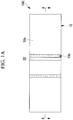
- the structure 100 which is manufactured by a manufacturing method of this embodiment, includes a plate-like carbon fiber composite material 10 and a support member 20 (another member) which is bonded to a polishing region 10c of the surface of the carbon fiber composite material 10 through an adhesive (not shown in the drawing).
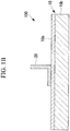
- the carbon fiber composite material 10 of the structure 100 includes a resin layer 10a disposed in the surface portion, and a carbon fiber layer 10b composed of a resin material containing carbon fibers.
- the support member 20 has an L-shape cross section.
- the carbon fiber composite material 10 is a carbon fiber reinforced plastic (CFRP) which is a resin material reinforced with carbon fibers.
- CFRP carbon fiber reinforced plastic
- the resin material may be, for example, a thermosetting resin, such as an unsaturated polyester or epoxy resin, or a thermoplastic resin, such as polyether ether ketone (PEEK).
- the carbon fiber composite material 10 has carbon fibers as a reinforcing material and the carbon fibers have conductivity. Therefore, if carbon fibers are exposed on the surface of the carbon fiber composite material 10, a stroke current from lightning striking the carbon fiber composite material 10 flows through carbon fibers and is released due to a dielectric breakdown between carbon fibers or edges of carbon fibers cut by polishing, which may cause a spark.
- the method of manufacturing the structure 100 according to this embodiment prevents carbon fibers from being exposed on the surface of the carbon fiber composite material 10 in the polishing step of polishing the surface of the carbon fiber composite material 10.
- the structure 100 is used, for example, as an integral tank which is a fuel tank integrated with the main wing of an aircraft with a wing structure that is a sealed structure that does not leak a liquid fuel.
- the support member 20 is used as a member for supporting the carbon fiber composite material 10 in the main wing.
- the resin layer 10a of the carbon fiber composite material 10 is a portion in contact with the liquid fuel in the integral tank.
- the method of manufacturing the structure 100 includes a molding step (S201) of molding the carbon fiber composite material 10, a polishing step (S202) of polishing the surface of the carbon fiber composite material 10 molded by the molding step (S201), and a bonding step (S203) of bonding the support member 20 to the surface of the carbon fiber composite material 10 polished in the polishing step (S202).
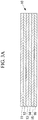
- Fig. 3A is a cross-sectional view showing the state where sheet-like prepregs 11, 12, 13, 14, 15, and 16 composed of carbon fibers impregnated with a resin material are stacked in the molding step.
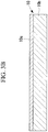
- Fig. 3B is a cross-sectional view of the carbon fiber composite material 10 after pressurization and heating of the stack of sheet-like prepregs 11, 12, 13, 14, 15, and 16 in the molding step.
- the resin layer 10a is a deposition of the resin material soaking out of the prepregs 11, 12, 13, 14, 15, and 16 upon curing by pressurization and heating of the thermosetting resin material.
- the carbon fiber layer 10b is composed of the cured resin material remaining around the carbon fibers without soaking as the resin layer 10a, and containing carbon fibers.
- the top layer in the resin layer 10a is a resin film (not shown in the drawing) that is stacked on the top surface of the prepreg 11 before curing of the resin material by pressurization and heating and that is integrated with the prepreg 11 by heating.
- the polishing region 10c in the surface of the carbon fiber composite material 10 molded in the molding step (S201) is polished with an abrasive having a predetermined hardness.
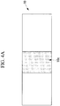
- Fig. 4A shows the polishing region 10c in the surface of the carbon fiber composite material 10.
- the abrasive may be any abrasive in which abrasive grains having a predetermined hardness are bonded to a base material (e.g., paper, a cloth, or a resin).
- a base material e.g., paper, a cloth, or a resin.
- a disc grinder or other grinders that rotate a disc-like abrasive can be used for polishing with an abrasive.
- the hardness of the abrasive grains in the abrasive is higher (Mohs hardness: 3-4) than that of the resin material portion of the resin layer 10a. For this reason, polishing the resin layer 10a with an abrasive cuts away the resin material portion of the resin layer 10a.
- the support member 20 is bonded, through an adhesive, to a bonding region 10d which is a part of the polishing region 10c in the surface of the carbon fiber composite material 10 polished in the polishing step (S202).
- Fig. 4B shows the polishing region 10c in the surface of the carbon fiber composite material 10 and the bonding region 10d which is a part thereof. As shown in Fig. 4B , the polishing region 10c is larger than the bonding region 10d. This is because the polishing region 10c which is larger than the bonding region 10d needs to be polished in order to ensure the reduction of asperities in the bonding region 10d to which the support member 20 is to be bonded.
- the polishing region 10c in the surface of the carbon fiber composite material 10 is larger than the bonding region 10d to which the support member 20 is to be bonded. Therefore, as shown in Fig. 4B , in the structure 100 in which the support member 20 is bonded to the bonding region 10d, a part of the polishing region 10c (the portion other than the area to which the support member 20 is to be bonded) is exposed on the surface.
- this polishing region 10c exposed on the surface is excessively polished in the polishing step and carbon fibers are exposed on the surface, the carbon fibers may discharge due to a dielectric breakdown, causing a spark.
- a protective filler 10e that has higher hardness than the abrasive is disposed in the resin layer 10a of the carbon fiber composite material 10.
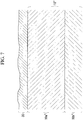
- Fig. 5 is a cross-sectional view showing the resin layer 10a and the carbon fiber layer 10b of the carbon fiber composite material 10 according to the first embodiment.
- the resin layer 10a of the carbon fiber composite material 10 is composed of a surface protective layer 10x that contains a particulate protective filler 10e (an abrasion-resistive member), and a polishing layer 10y that does not contain the protective filler 10e.
- the protective filler 10e is composed of particles that have higher hardness than the abrasive grains in the abrasive.
- the grain size of the protective filler 10e is preferably in the range of 20 ⁇ m to 40 ⁇ m.
- quartz Mohs hardness: 7
- aluminum nitride Mohs hardness: 8
- silicon carbide Mohs hardness: 9.8 or the like that has higher hardness than glass
- quartz Mohs hardness: 7
- aluminum nitride Mohs hardness: 8
- silicon carbide Mohs hardness: 9.8 or the like that has higher hardness than quartz
- aluminum nitride Mohs hardness: 8
- silicon carbide Mohs hardness: 9.8 or the like that has higher hardness than aluminum nitride can be used as the protective filler 10e.
- a mixture of a resin material, which is to be impregnated into carbon fibers, and the protective filler 10e is used for the prepreg 11 stacked before pressurization and heating in the molding step (S201).
- the protective filler 10e is mixed into the resin material soaked out of the prepreg 11 due to pressurization and heating in the molding step (S201), and the resin material is then cured. Accordingly, the surface protective layer 10x is formed in which the resin layer 10a of the carbon fiber composite material 10 molded in the molding step (S201) contains the protective filler 10e.
- a resin film (not shown in the drawing) is stacked on the top surface of the prepreg 11 before pressurization and heating in the molding step (S201).
- the polishing layer 10y polished for increasing adhesion is formed in the top layer, and the surface protective layer 10x containing the protective filler 10e that has higher hardness than the abrasive is lower than the polishing layer 10y such that the carbon fiber composite material 10 is protected from the abrasive.
- the protective filler 10e contained in the surface protective layer 10x suppresses excessive abrasion of the resin layer 10a.
- the abrasive comes into contact with the protective filler 10e when abrasion reaches a surface S2 (the surface of the surface protective layer 10x). This further suppresses excessive abrasion of the resin layer 10a.
- a resin material mixed with the protective filler 10e is used for the prepreg 11 disposed adjacent to the top surface (the surface to which the support member 20 is to be bonded) of the carbon fiber composite material 10 in the above description, which is not necessarily the case.
- a resin material mixed with the protective filler 10e may be used for the prepreg 11 and the prepreg 12. Further, a resin material mixed with the protective filler 10e may be used for the prepregs 13, 14, 15, and 16.
- the polishing layer 10y having hardness lower than that of the abrasive is formed in the top layer, and the surface protective layer 10x containing the particulate protective filler 10e (abrasion-resistive member) having hardness higher than the hardness of the abrasive such that the carbon fiber composite material 10 is protected from the abrasive is formed in a layer lower than the polishing layer 10y.
- the polishing layer 10y and the surface protective layer 10x provide appropriate protection such that abrasion of the resin material in the polishing region with the abrasive does not expose carbon fibers on the surface of the carbon fiber composite material 10, independently of work environments.
- polishing work for polishing the surface of the carbon fiber composite material 10 can be easily performed without exposing carbon fibers on the surface, independently of work environments and the like.
- the molding step (S201) cures the prepreg 11 impregnated with a resin material mixed with the particulate protective filler 10e and molds the carbon fiber composite material 10.
- the surface protective layer 10x formed with the particulate protective filler 10e in the carbon fiber composite material 10 can provide protection such that carbon fibers are not exposed on the surface of the carbon fiber composite material 10 in the polishing step (S202).
- the abrasive has hardness higher than that of the resin material contained in the carbon fiber composite material 10 formed in the molding step (S201).
- the resin material portion of the surface of the carbon fiber composite material 10 is polished with the abrasive having higher hardness than the resin material, so that the surface protective layer 10x can provide protection such that carbon fibers are not exposed on the surface of the carbon fiber composite material 10 in the polishing step (S202).
- the method of manufacturing a structure according to this embodiment is the same as the method of manufacturing a structure according to the first embodiment except the molding step (S201) shown in Fig. 2 . Therefore, the method of manufacturing a structure according to this embodiment is the same as the first embodiment except the case described below, and the description of the common points will be omitted below.
- a mixture of a resin material, which is to be impregnated into carbon fibers, and the protective filler 10e is used for the prepreg 11 stacked before pressurization and heating in the molding step (S201).
- protective supports are disposed in multiple spots on the surface of the prepreg 11 stacked before pressurization and heating in the molding step (S201).
- Fig. 6 is a cross-sectional view showing the resin layer 10a' and the carbon fiber layer 10b' of the carbon fiber composite material 10' according to this embodiment.
- the resin layer 10a' of the carbon fiber composite material 10' is composed of a surface protective layer 10x' that contains protective supports 10f (abrasion-resistive members), and a polishing layer 10y' that does not contain the protective supports 10f.
- columnar protective supports 10f extending in the thickness direction of the resin layer 10a' (in the vertical direction in Fig. 6 ) are disposed.
- the protective supports 10f are columnar (for example, circular cylindrical) members that have higher hardness than the abrasive grains in the abrasive.
- the diameter of the protective supports 10f is preferably less than or equal to 40 ⁇ m.
- the protective supports 10f can be composed of glass, quartz, aluminum nitride, silicon carbide, or the like.
- the protective supports 10f extend in the thickness direction of the resin layer 10a' and are shorter than the thickness of the resin layer 10a'. In other words, the ends of the protective supports 10f adjacent to the top surface of the carbon fiber composite material 10' are disposed inside the resin layer 10a'.
- protective supports 10f are disposed in multiple spots on the surface of the prepreg 11 stacked before pressurization and heating in the molding step (S201).
- the positions where the protective supports 10f are disposed include at least the polishing region 10c.
- a resin film (not shown in the drawing) is stacked on the top surface of the prepreg 11 before pressurization and heating in the molding step (S201).
- the resin layer 10a' is cured with the multiple protective supports 10f disposed in the resin layer 10a' composed of the resin material soaked out of the prepreg 11 due to pressurization and heating in the molding step (S201).
- the protective supports 10f are disposed in the resin layer 10a' of the carbon fiber composite material 10 molded in the molding step (S201).
- the polishing layer 10y' polished for increasing adhesion is formed in the top layer, and the surface protective layer 10x' containing the protective supports 10f that have higher hardness than the abrasive is located lower than the polishing layer 10y' such that the carbon fiber composite material 10 is protected from the abrasive.
- the protective supports 10f suppress excessive abrasion of the resin layer 10a'.
- the resin layer 10a' having a surface S3 with asperities as shown in Fig. 6 is polished with an abrasive, the abrasive comes into contact with the protective supports 10f when abrasion reaches a surface S4. This further suppresses excessive abrasion of the resin layer 10a'.
- the columnar protective supports 10f are disposed in multiple spots on the surface of the prepreg 11 disposed in the polishing region 10c, and the prepregs 11, 12, 13, 14, 15, and 16 are cured to form the carbon fiber composite material 10'.
- the surface protective layer 10x' formed with the protective supports 10f in multiple spots in the carbon fiber composite material 10 can provide protection such that carbon fibers are not exposed on the surface of the carbon fiber composite material 10' in the polishing step (S202).
- the length of the protective supports 10f is smaller than the thickness of the resin layer 10a'.
- the columnar abrasion-resistive members are made shorter than the thickness of the resin layer 10a' so that the resin material can be partly polished.
- the method of manufacturing a structure according to this embodiment is the same as the method of manufacturing a structure according to the first embodiment except the molding step (S201) shown in Fig. 2 . Therefore, the method of manufacturing a structure according to this embodiment is the same as the first embodiment except the case described below, and the description of the common points will be omitted below.
- a mixture of a resin material, which is to be impregnated into carbon fibers, and the protective filler 10e is used for the prepreg 11 stacked before pressurization and heating in the molding step (S201).
- a prepreg (not shown in the drawing) composed of glass fibers impregnated with a resin material is additionally disposed in a layer higher than the prepregs 11, 12, 13, 14, 15, and 16 stacked before pressurization and heating in the molding step (S201), and a non-conductive glass fiber composite material 30 (non-conductive layer) is formed in the highest top layer of the carbon fiber composite material 10.
- Fig. 7 is a cross-sectional view showing the resin layer 10a" and the carbon fiber layer 10b" of the carbon fiber composite material 10" according to this embodiment.
- a surface protective layer composed of the glass fiber composite material 30 is formed in a layer higher than the resin layer 10a" of the carbon fiber composite material 10" according to this embodiment.
- a prepreg (not shown in the drawing) composed of glass fibers impregnated with a resin material is disposed in a layer higher than the prepregs 11, 12, 13, 14, 15, and 16 stacked before pressurization and heating in the molding step (S201).
- the glass fiber composite material 30 cured together with the carbon fiber composite material 10" is formed in a layer higher than the resin layer 10a" composed of the resin material soaking out of the prepregs 11, 12, 13, 14, 15, and 16 due to pressurization and heating in the molding step (S201).
- the glass fiber composite material 30 is disposed in a layer higher than the resin layer 10a" of the carbon fiber composite material 10" molded in the molding step (S201).
- the molding step (S201) forms the resin layer 10a" with the non-conductive glass fiber composite material 30 formed in a layer higher than the resin layer 10a" such that the carbon fiber composite material 10" is protected from the abrasive.
- the resin layer 10a" is not polished as long as the glass fiber composite material 30 remains, so that exposure of the carbon fiber layer 10b" is suppressed.
- the glass fiber composite material 30 is disposed in a layer higher than the resin layer 10a".
- the glass fiber composite material 30 can provide protection such that the carbon fiber layer 10b" is not exposed on the surface of the carbon fiber composite material 10" in the polishing step (S202).
- VaRTM vacuum assisted resin transfer molding
Landscapes
- Engineering & Computer Science (AREA)
- Mechanical Engineering (AREA)
- Chemical & Material Sciences (AREA)
- Composite Materials (AREA)
- Laminated Bodies (AREA)
- Moulding By Coating Moulds (AREA)
- Reinforced Plastic Materials (AREA)
- Grinding Of Cylindrical And Plane Surfaces (AREA)
- Casting Or Compression Moulding Of Plastics Or The Like (AREA)
Abstract
Description
- The present invention relates to a method of manufacturing a structure including a carbon fiber composite material composed of a resin material reinforced with carbon fibers, and a structure.
- A lightweight and high-strength material with high durability has been required as an airframe material used for the main wing, the integral tank, and the like of an aircraft. For example, a lightweight metal material, such as an aluminum alloy, is used as an airframe material. In addition, with a recent increasing demand for these, a carbon fiber composite material composed of a resin material reinforced with carbon fibers has been used as an airframe material.
- When another member is bonded to a carbon fiber composite material, it is preferable to polish, with an abrasive, a bonding region of the surface of the carbon fiber composite material to which the other member is to be bonded, to reduce asperities, thereby increasing the adhesion between the carbon fiber composite material and the other member. In this case, to ensure the reduction of asperities of the bonding region to which the other member is to be bonded, it is necessary to polish a region larger than the bonding region.
- However, if a region larger than the bonding region is polished, a polishing region which has been polished with an abrasive after the other member is bonded to the surface of the carbon fiber composite material is partly exposed as a surface of the carbon fiber composite material.
- If the surface of the carbon fiber composite material is excessively polished with an abrasive, carbon fibers are partly exposed on the surface of the carbon fiber composite material.
- In this case, if lightning strikes the carbon fiber composite material, carbon fibers exposed on the surface of the carbon fiber composite material may discharge upon a dielectric breakdown, thereby causing a spark (edge glow phenomenon).
- For this reason, when the surface of the carbon fiber composite material is polished with an abrasive, it is preferable to avoid exposure of carbon fibers on the surface of the carbon fiber composite material.
-
PTL 1 discloses forming a second resin layer below a first resin layer formed on the surface of a fiber reinforcing resin composite material with a color different from that of the first resin layer. According toPTL 1, visual checking of a change in the color of the particulate resin abrasive suppresses polishing of fibers. - {PTL 1}
Japanese Unexamined Patent Application, Publication No.2008-55770 - However, according to
PTL 1, if visual checking is not accurately performed, the second resin layer is polished and fibers are exposed on the surface. - Besides, even with visual checking, there is a risk of a failure in checking a change in the color of the particulate resin abrasive due to the illuminance or the like in the environment of polishing work, so that the second resin layer may be polished and fibers may be exposed on the surface.
- It is an object of the present invention, which has been made in view of this background, to provide a method of manufacturing a structure, and a structure that allow polishing work for polishing the surface of a carbon fiber composite material without exposing carbon fibers on the surface, to be easily performed independently of work environments and the like.
- To solve the above-described problem, the present invention employs the following solutions.
- A method of manufacturing a structure according to one aspect of the present invention is a method of manufacturing a structure including a carbon fiber composite material composed of a resin material reinforced with carbon fibers. The method includes: a molding step of impregnating the carbon fibers with the resin material and curing the resin material for molding the carbon fiber composite material; a polishing step of polishing a polishing region on a surface of the carbon fiber composite material molded in the molding step, with an abrasive that has a predetermined hardness; and a bonding step of bonding, through an adhesive, another member to a part of the polishing region polished by the polishing step. The molding step forms, in a top layer, a polishing layer that has hardness lower than the predetermined hardness, and forms a surface protective layer that is lower than the polishing layer, protects the carbon fiber composite material from the abrasive, and has hardness higher than the predetermined hardness.
- In the method of manufacturing a structure according to one aspect of the present invention, in the molding step of molding the carbon fiber composite material, the polishing layer having hardness lower than the predetermined hardness is formed in the top layer, and the surface protective layer having hardness higher than the predetermined hardness such that the carbon fiber composite material is protected from the abrasive is formed in the layer lower than the polishing layer. Therefore, in the polishing step of polishing the polishing region in the surface of the carbon fiber composite material, the polishing layer and the surface protective layer provide appropriate protection such that abrasion of the resin material in the polishing region with the abrasive does not expose carbon fibers on the surface of the carbon fiber composite material, independently of work environments.
- Thus, in the method of manufacturing a structure according to one aspect of the present invention, polishing work for polishing the surface of the carbon fiber composite material can be easily performed without exposing carbon fibers on the surface, independently of work environments and the like.
- In the method of manufacturing a structure according to one aspect of the present invention, the molding step may dispose, in the carbon fiber composite material, an abrasion-resistive member that has hardness higher than the predetermined hardness, thereby forming the surface protective layer.
- Thus, the abrasion-resistive member is disposed in the carbon fiber composite material so that a portion near the surface of the carbon fiber composite material can be a surface protective layer.
- In the method of manufacturing a structure described above, the molding step may impregnate the resin material mixed with the abrasion-resistive member and cure the resin material, thereby molding the carbon fiber composite material, the abrasion-resistive member being particulate.
- Thus, the surface protective layer formed with the particulate abrasion-resistive member in the carbon fiber composite material can provide protection such that carbon fibers are not exposed on the surface of the carbon fiber composite material in the polishing step.
- In the method of manufacturing a structure described above, the molding step may dispose the abrasion-resistive member in multiple spots on the surface of the carbon fibers disposed in the polishing region and cure the resin material, thereby forming the carbon fiber composite material, the abrasion-resistive member being columnar.
- Thus, the surface protective layer formed with the abrasion-resistive member in multiple spots on the surface of the carbon fibers can provide protection such that carbon fibers are not exposed on the surface of the carbon fiber composite material in the polishing step.
- A method of manufacturing a structure according to one aspect of the present invention includes a carbon fiber composite material composed of a resin material reinforced with carbon fibers. The method includes: a molding step of impregnating the carbon fibers with the resin material and curing the resin material for molding the carbon fiber composite material; a polishing step of polishing a polishing region on a surface of the carbon fiber composite material molded in the molding step, with an abrasive that has a predetermined hardness; a bonding step of bonding, through an adhesive, another member to a part of the polishing region polished by the polishing step. The molding step forms, in a top layer, a non-conductive layer for protecting the carbon fiber composite material from the abrasive.
- In the method of manufacturing a structure according to one aspect of the present invention, in the molding step of molding the carbon fiber composite material, the non-conductive layer that protects the carbon fiber composite material from the abrasive is formed on in the top layer. Therefore, in the polishing step of polishing the polishing region in the surface of the carbon fiber composite material, the resin material in the polishing region is not polished as long as the non-conductive layer remains, so that appropriate protection is made such that the carbon fibers are not exposed on the surface of the carbon fiber composite material.
- In the method of manufacturing a structure according to one aspect of the present invention, the non-conductive layer may be a layer molded with a glass fiber composite material that is a resin material reinforced with glass fibers.
- Thus, a glass fiber composite material reinforced with glass fibers serves as a non-conductive layer, so that protection can be made such that the carbon fibers are not exposed on the surface of the carbon fiber composite material in the polishing step.
- In the method of manufacturing a structure according to one aspect of the present invention, the predetermined hardness may be higher than the hardness of the resin material contained in the carbon fiber composite material formed in the molding step.
- Thus, the resin material portion of the surface of the carbon fiber composite material is polished with the abrasive having higher hardness than the resin material, so that the surface protective layer can provide protection such that carbon fibers are not exposed on the surface of the carbon fiber composite material in the polishing step.
- A structure according to one aspect of the present invention is formed with a carbon fiber composite material that is a resin material reinforced with carbon fibers and polished with an abrasive with a predetermined hardness. The structure includes: a polishing layer that is formed in a top layer and has hardness lower than the predetermined hardness; a surface protective layer that is lower than the polishing layer, protects the carbon fiber composite material from the abrasive, and has hardness higher than the predetermined hardness; and a carbon fiber layer composed of the cured resin material containing the carbon fibers therein.
- The structure according to one aspect of the present invention allows polishing work for polishing the surface of a carbon fiber composite material without exposing carbon fibers on the surface, to be easily performed independently of work environments and the like.
- The present invention can provide a method of manufacturing a structure, and a structure that allow polishing work for polishing the surface of a carbon fiber composite material without exposing carbon fibers on the surface, to be easily performed independently of work environments and the like.
-
- {
Fig. 1A} Fig. 1A is a diagram showing a plan view of a structure including a carbon fiber composite material. - {
Fig. 1B} Fig. 1B is a diagram showing a cross-sectional view of a structure including a composite material along line A-A inFig. 1A . - {
Fig. 2} Fig. 2 is a flow chart of a process for manufacturing a structure including a carbon fiber composite material. - {
Fig. 3A} Fig. 3A is a cross-sectional view of carbon fiber composite material showing the state before pressurization and heating. - {
Fig. 3B} Fig. 3B is a cross-sectional view of carbon fiber composite material showing the state after pressurization and heating. - {
Fig. 4A} Fig. 4A is a diagram showing a polishing region of the surface of the carbon fiber composite material. - {
Fig. 4B} Fig. 4B is a diagram showing a bonding region of the surface of the carbon fiber composite material. - {
Fig. 5} Fig. 5 is a cross-sectional view of a resin layer of a carbon fiber composite material according to the first embodiment. - {
Fig. 6} Fig. 6 is a cross-sectional view of a resin layer of a carbon fiber composite material according to the second embodiment. - {
Fig. 7} Fig. 7 is a cross-sectional view of a resin layer of a carbon fiber composite material and a glass fiber composite material according to the third embodiment. - A method of manufacturing a
structure 100 according to the first embodiment of the present invention will now be described with reference to the drawings. - As shown in
Fig. 1A , thestructure 100, which is manufactured by a manufacturing method of this embodiment, includes a plate-like carbonfiber composite material 10 and a support member 20 (another member) which is bonded to a polishingregion 10c of the surface of the carbonfiber composite material 10 through an adhesive (not shown in the drawing). - As shown in
Fig. 1B , the carbonfiber composite material 10 of thestructure 100 includes aresin layer 10a disposed in the surface portion, and acarbon fiber layer 10b composed of a resin material containing carbon fibers. - Further, as shown in
Figs. 1A and1B , thesupport member 20 has an L-shape cross section. - The carbon
fiber composite material 10 is a carbon fiber reinforced plastic (CFRP) which is a resin material reinforced with carbon fibers. The resin material may be, for example, a thermosetting resin, such as an unsaturated polyester or epoxy resin, or a thermoplastic resin, such as polyether ether ketone (PEEK). - The carbon
fiber composite material 10 has carbon fibers as a reinforcing material and the carbon fibers have conductivity. Therefore, if carbon fibers are exposed on the surface of the carbonfiber composite material 10, a stroke current from lightning striking the carbonfiber composite material 10 flows through carbon fibers and is released due to a dielectric breakdown between carbon fibers or edges of carbon fibers cut by polishing, which may cause a spark. - For this reason, the method of manufacturing the
structure 100 according to this embodiment prevents carbon fibers from being exposed on the surface of the carbonfiber composite material 10 in the polishing step of polishing the surface of the carbonfiber composite material 10. - The
structure 100 is used, for example, as an integral tank which is a fuel tank integrated with the main wing of an aircraft with a wing structure that is a sealed structure that does not leak a liquid fuel. In this case, thesupport member 20 is used as a member for supporting the carbonfiber composite material 10 in the main wing. In addition, theresin layer 10a of the carbonfiber composite material 10 is a portion in contact with the liquid fuel in the integral tank. - A method of manufacturing the
structure 100 according to this embodiment will now be described. - As shown in the flow chart of
Fig. 2 , the method of manufacturing thestructure 100 according to this embodiment includes a molding step (S201) of molding the carbonfiber composite material 10, a polishing step (S202) of polishing the surface of the carbonfiber composite material 10 molded by the molding step (S201), and a bonding step (S203) of bonding thesupport member 20 to the surface of the carbonfiber composite material 10 polished in the polishing step (S202). - In the molding step (S201) multiple sheet-like prepregs composed of carbon fibers impregnated with a resin material are stacked, pressurized, and heated to cure the multiple prepregs for integration.
-
Fig. 3A is a cross-sectional view showing the state where sheet-like prepregs -
Fig. 3B is a cross-sectional view of the carbonfiber composite material 10 after pressurization and heating of the stack of sheet-like prepregs - In
Fig. 3B , theresin layer 10a is a deposition of the resin material soaking out of theprepregs carbon fiber layer 10b is composed of the cured resin material remaining around the carbon fibers without soaking as theresin layer 10a, and containing carbon fibers. - It should be noted that the top layer in the
resin layer 10a is a resin film (not shown in the drawing) that is stacked on the top surface of theprepreg 11 before curing of the resin material by pressurization and heating and that is integrated with theprepreg 11 by heating. - In the polishing step (S202), the polishing
region 10c in the surface of the carbonfiber composite material 10 molded in the molding step (S201) is polished with an abrasive having a predetermined hardness. -
Fig. 4A shows the polishingregion 10c in the surface of the carbonfiber composite material 10. The abrasive may be any abrasive in which abrasive grains having a predetermined hardness are bonded to a base material (e.g., paper, a cloth, or a resin). In addition, for polishing with an abrasive, a disc grinder or other grinders that rotate a disc-like abrasive can be used. - It should be noted that the hardness of the abrasive grains in the abrasive is higher (Mohs hardness: 3-4) than that of the resin material portion of the
resin layer 10a. For this reason, polishing theresin layer 10a with an abrasive cuts away the resin material portion of theresin layer 10a. - In the bonding step (S203), the
support member 20 is bonded, through an adhesive, to abonding region 10d which is a part of the polishingregion 10c in the surface of the carbonfiber composite material 10 polished in the polishing step (S202). -
Fig. 4B shows the polishingregion 10c in the surface of the carbonfiber composite material 10 and thebonding region 10d which is a part thereof. As shown inFig. 4B , the polishingregion 10c is larger than thebonding region 10d. This is because the polishingregion 10c which is larger than thebonding region 10d needs to be polished in order to ensure the reduction of asperities in thebonding region 10d to which thesupport member 20 is to be bonded. - As described above, the polishing
region 10c in the surface of the carbonfiber composite material 10 is larger than thebonding region 10d to which thesupport member 20 is to be bonded. Therefore, as shown inFig. 4B , in thestructure 100 in which thesupport member 20 is bonded to thebonding region 10d, a part of the polishingregion 10c (the portion other than the area to which thesupport member 20 is to be bonded) is exposed on the surface. - If this polishing
region 10c exposed on the surface is excessively polished in the polishing step and carbon fibers are exposed on the surface, the carbon fibers may discharge due to a dielectric breakdown, causing a spark. - For this reason, in this embodiment, to prevent the polishing
region 10c from being excessively polished in the polishing step (S202) and carbon fibers from being exposed on the surface, aprotective filler 10e that has higher hardness than the abrasive is disposed in theresin layer 10a of the carbonfiber composite material 10. -
Fig. 5 is a cross-sectional view showing theresin layer 10a and thecarbon fiber layer 10b of the carbonfiber composite material 10 according to the first embodiment. - As shown in
Fig. 5 , theresin layer 10a of the carbonfiber composite material 10 according to this embodiment is composed of a surfaceprotective layer 10x that contains a particulateprotective filler 10e (an abrasion-resistive member), and apolishing layer 10y that does not contain theprotective filler 10e. Theprotective filler 10e is composed of particles that have higher hardness than the abrasive grains in the abrasive. The grain size of theprotective filler 10e is preferably in the range of 20 µm to 40 µm. - For example, when glass (Mohs hardness: 5-6) is used as abrasive grains for the abrasive, quartz (Mohs hardness: 7), aluminum nitride (Mohs hardness: 8), silicon carbide (Mohs hardness: 9.8) or the like that has higher hardness than glass can be used as the
protective filler 10e. In addition, when quartz (Mohs hardness: 7) is used as abrasive grains for the abrasive, aluminum nitride (Mohs hardness: 8), silicon carbide (Mohs hardness: 9.8) or the like that has higher hardness than quartz can be used as theprotective filler 10e. In addition, when aluminum nitride (Mohs hardness: 8) is used as abrasive grains for the abrasive, silicon carbide (Mohs hardness: 9.8) or the like that has higher hardness than aluminum nitride can be used as theprotective filler 10e. - To form the surface
protective layer 10x containing theprotective filler 10e shown inFig. 5 , a mixture of a resin material, which is to be impregnated into carbon fibers, and theprotective filler 10e is used for theprepreg 11 stacked before pressurization and heating in the molding step (S201). - Thus, the
protective filler 10e is mixed into the resin material soaked out of theprepreg 11 due to pressurization and heating in the molding step (S201), and the resin material is then cured. Accordingly, the surfaceprotective layer 10x is formed in which theresin layer 10a of the carbonfiber composite material 10 molded in the molding step (S201) contains theprotective filler 10e. - Further, to form the
polishing layer 10y in the top layer, a resin film (not shown in the drawing) is stacked on the top surface of theprepreg 11 before pressurization and heating in the molding step (S201). - As described above, in the molding step (S201), the
polishing layer 10y polished for increasing adhesion is formed in the top layer, and the surfaceprotective layer 10x containing theprotective filler 10e that has higher hardness than the abrasive is lower than thepolishing layer 10y such that the carbonfiber composite material 10 is protected from the abrasive. - Even if the carbon
fiber composite material 10 including theresin layer 10a shown inFig. 5 is polished with an abrasive that has lower hardness than theprotective filler 10e in the polishing step, theprotective filler 10e contained in the surfaceprotective layer 10x suppresses excessive abrasion of theresin layer 10a. - For example, when the
resin layer 10a having a surface S1 with asperities as shown inFig. 5 is polished with an abrasive, the abrasive comes into contact with theprotective filler 10e when abrasion reaches a surface S2 (the surface of the surfaceprotective layer 10x). This further suppresses excessive abrasion of theresin layer 10a. - A resin material mixed with the
protective filler 10e is used for theprepreg 11 disposed adjacent to the top surface (the surface to which thesupport member 20 is to be bonded) of the carbonfiber composite material 10 in the above description, which is not necessarily the case. A resin material mixed with theprotective filler 10e may be used for theprepreg 11 and theprepreg 12. Further, a resin material mixed with theprotective filler 10e may be used for theprepregs - The actions and effects provided by the aforementioned method of manufacturing the
structure 100 according to this embodiment will be described. - In the method of manufacturing a structure according to this embodiment, in the molding step (S201) of molding the carbon
fiber composite material 10, thepolishing layer 10y having hardness lower than that of the abrasive is formed in the top layer, and the surfaceprotective layer 10x containing the particulateprotective filler 10e (abrasion-resistive member) having hardness higher than the hardness of the abrasive such that the carbonfiber composite material 10 is protected from the abrasive is formed in a layer lower than thepolishing layer 10y. - Therefore, in the polishing step (S202) of polishing the polishing
region 10c in the surface of the carbonfiber composite material 10, thepolishing layer 10y and the surfaceprotective layer 10x provide appropriate protection such that abrasion of the resin material in the polishing region with the abrasive does not expose carbon fibers on the surface of the carbonfiber composite material 10, independently of work environments. - Thus, in the method of manufacturing a structure according to this embodiment, polishing work for polishing the surface of the carbon
fiber composite material 10 can be easily performed without exposing carbon fibers on the surface, independently of work environments and the like. - In the method of manufacturing the structure according to this embodiment, the molding step (S201) cures the
prepreg 11 impregnated with a resin material mixed with the particulateprotective filler 10e and molds the carbonfiber composite material 10. - Thus, the surface
protective layer 10x formed with the particulateprotective filler 10e in the carbonfiber composite material 10 can provide protection such that carbon fibers are not exposed on the surface of the carbonfiber composite material 10 in the polishing step (S202). - In the method of manufacturing a structure according to this embodiment, the abrasive has hardness higher than that of the resin material contained in the carbon
fiber composite material 10 formed in the molding step (S201). - Thus, the resin material portion of the surface of the carbon
fiber composite material 10 is polished with the abrasive having higher hardness than the resin material, so that the surfaceprotective layer 10x can provide protection such that carbon fibers are not exposed on the surface of the carbonfiber composite material 10 in the polishing step (S202). - A method of manufacturing a structure according to the second embodiment of the present invention will now be described with reference to the drawings.
- The method of manufacturing a structure according to this embodiment is the same as the method of manufacturing a structure according to the first embodiment except the molding step (S201) shown in
Fig. 2 . Therefore, the method of manufacturing a structure according to this embodiment is the same as the first embodiment except the case described below, and the description of the common points will be omitted below. - In the method of manufacturing a structure according to the first embodiment, a mixture of a resin material, which is to be impregnated into carbon fibers, and the
protective filler 10e is used for theprepreg 11 stacked before pressurization and heating in the molding step (S201). - On the contrary, in the method of manufacturing a structure according to this embodiment, protective supports are disposed in multiple spots on the surface of the
prepreg 11 stacked before pressurization and heating in the molding step (S201). -
Fig. 6 is a cross-sectional view showing theresin layer 10a' and thecarbon fiber layer 10b' of the carbon fiber composite material 10' according to this embodiment. - The
resin layer 10a' of the carbon fiber composite material 10' according to this embodiment is composed of a surfaceprotective layer 10x' that containsprotective supports 10f (abrasion-resistive members), and apolishing layer 10y' that does not contain theprotective supports 10f. - As shown in
Fig. 6 , in the surfaceprotective layer 10x' of the carbon fiber composite material 10' according to this embodiment, columnarprotective supports 10f extending in the thickness direction of theresin layer 10a' (in the vertical direction inFig. 6 ) are disposed. The protective supports 10f are columnar (for example, circular cylindrical) members that have higher hardness than the abrasive grains in the abrasive. The diameter of theprotective supports 10f is preferably less than or equal to 40 µm. - Like the
protective filler 10e in the first embodiment, theprotective supports 10f can be composed of glass, quartz, aluminum nitride, silicon carbide, or the like. - The
protective supports 10f extend in the thickness direction of theresin layer 10a' and are shorter than the thickness of theresin layer 10a'. In other words, the ends of theprotective supports 10f adjacent to the top surface of the carbon fiber composite material 10' are disposed inside theresin layer 10a'. - To form the
resin layer 10a' containing theprotective supports 10f shown inFig. 6 ,protective supports 10f are disposed in multiple spots on the surface of theprepreg 11 stacked before pressurization and heating in the molding step (S201). The positions where theprotective supports 10f are disposed include at least the polishingregion 10c. - Further, to form the
polishing layer 10y' in the top layer, a resin film (not shown in the drawing) is stacked on the top surface of theprepreg 11 before pressurization and heating in the molding step (S201). - Thus, the
resin layer 10a' is cured with the multipleprotective supports 10f disposed in theresin layer 10a' composed of the resin material soaked out of theprepreg 11 due to pressurization and heating in the molding step (S201). - Accordingly, the
protective supports 10f are disposed in theresin layer 10a' of the carbonfiber composite material 10 molded in the molding step (S201). - As described above, in the molding step (S201), the
polishing layer 10y' polished for increasing adhesion is formed in the top layer, and the surfaceprotective layer 10x' containing theprotective supports 10f that have higher hardness than the abrasive is located lower than thepolishing layer 10y' such that the carbonfiber composite material 10 is protected from the abrasive. - Even if the carbon fiber composite material 10' including the
resin layer 10a' shown inFig. 6 is polished with an abrasive that has lower hardness than theprotective supports 10f in the polishing step, theprotective supports 10f suppress excessive abrasion of theresin layer 10a'. For example, when theresin layer 10a' having a surface S3 with asperities as shown inFig. 6 is polished with an abrasive, the abrasive comes into contact with theprotective supports 10f when abrasion reaches a surface S4. This further suppresses excessive abrasion of theresin layer 10a'. - As described above, in the method of manufacturing a structure according to this embodiment, in the molding step (S201), the columnar
protective supports 10f are disposed in multiple spots on the surface of theprepreg 11 disposed in the polishingregion 10c, and theprepregs - Thus, the surface
protective layer 10x' formed with theprotective supports 10f in multiple spots in the carbonfiber composite material 10 can provide protection such that carbon fibers are not exposed on the surface of the carbon fiber composite material 10' in the polishing step (S202). - Further, in the method of manufacturing a structure according to this embodiment, the length of the
protective supports 10f is smaller than the thickness of theresin layer 10a'. - Thus, while abrasion of carbon fibers is prevented by the columnar
protective supports 10f, the columnar abrasion-resistive members are made shorter than the thickness of theresin layer 10a' so that the resin material can be partly polished. - A method of manufacturing a structure according to the third embodiment of the present invention will now be described with reference to the drawings.
- The method of manufacturing a structure according to this embodiment is the same as the method of manufacturing a structure according to the first embodiment except the molding step (S201) shown in
Fig. 2 . Therefore, the method of manufacturing a structure according to this embodiment is the same as the first embodiment except the case described below, and the description of the common points will be omitted below. - In the method of manufacturing a structure according to the first embodiment, a mixture of a resin material, which is to be impregnated into carbon fibers, and the
protective filler 10e is used for theprepreg 11 stacked before pressurization and heating in the molding step (S201). - On the contrary, in the method of manufacturing a structure according to this embodiment, a prepreg (not shown in the drawing) composed of glass fibers impregnated with a resin material is additionally disposed in a layer higher than the
prepregs fiber composite material 10. -
Fig. 7 is a cross-sectional view showing theresin layer 10a" and thecarbon fiber layer 10b" of the carbonfiber composite material 10" according to this embodiment. - As shown in
Fig. 7 , a surface protective layer composed of the glassfiber composite material 30 is formed in a layer higher than theresin layer 10a" of the carbonfiber composite material 10" according to this embodiment. - To form the glass
fiber composite material 30 in a layer higher than theresin layer 10a" as shown inFig. 7 , a prepreg (not shown in the drawing) composed of glass fibers impregnated with a resin material is disposed in a layer higher than theprepregs - Thus, the glass
fiber composite material 30 cured together with the carbonfiber composite material 10" is formed in a layer higher than theresin layer 10a" composed of the resin material soaking out of theprepregs - Accordingly, the glass
fiber composite material 30 is disposed in a layer higher than theresin layer 10a" of the carbonfiber composite material 10" molded in the molding step (S201). - As described above, the molding step (S201) forms the
resin layer 10a" with the non-conductive glassfiber composite material 30 formed in a layer higher than theresin layer 10a" such that the carbonfiber composite material 10" is protected from the abrasive. - Even if the glass
fiber composite material 30 shown inFig. 7 is polished in the polishing step, theresin layer 10a" is not polished as long as the glassfiber composite material 30 remains, so that exposure of thecarbon fiber layer 10b" is suppressed. - As described above, in the method of manufacturing a structure according to this embodiment, in the molding step (S201), the glass
fiber composite material 30 is disposed in a layer higher than theresin layer 10a". - Thus, the glass
fiber composite material 30 can provide protection such that thecarbon fiber layer 10b" is not exposed on the surface of the carbonfiber composite material 10" in the polishing step (S202). - Although the fiber composite material is molded using prepregs in the first to third embodiments, vacuum assisted resin transfer molding (VaRTM) in which stacked fiber cloth is impregnated with a resin material for molding may be used instead.
-
- 10, 10', 10"
- carbon fiber composite material
- 10a, 10a', 10a"
- resin layer
- 10b, 10b', 10b"
- carbon fiber layer
- 10c
- polishing region
- 10d
- bonding region
- 10e
- protective filler (abrasion-resistive member)
- 10f
- protective support (abrasion-resistive member)
- 10x
- surface protective layer
- 10y
- polishing layer
- 11, 12, 13, 14, 15, and 16
- prepreg
- 20
- support member (another member)
- 30
- glass fiber composite material
- 100
- structure
Claims (8)
- A method of manufacturing a structure including a carbon fiber composite material composed of a resin material reinforced with carbon fibers, the method comprising:a molding step of impregnating the carbon fibers with the resin material and curing the resin material for molding the carbon fiber composite material;a polishing step of polishing a polishing region on a surface of the carbon fiber composite material molded in the molding step, with an abrasive that has a predetermined hardness; anda bonding step of bonding, through an adhesive, another member to a part of the polishing region polished by the polishing step, whereinthe molding step forms, in a top layer, a polishing layer that has hardness lower than the predetermined hardness, and forms a surface protective layer that is lower than the polishing layer, protects the carbon fiber composite material from the abrasive, and has hardness higher than the predetermined hardness.
- The method of manufacturing a structure according to Claim 1, wherein the molding step disposes, in the carbon fiber composite material, an abrasion-resistive member that has hardness higher than the predetermined hardness, thereby forming the surface protective layer.
- The method of manufacturing a structure according to Claim 2, wherein the molding step impregnates the resin material mixed with the abrasion-resistive member and cures the resin material, thereby molding the carbon fiber composite material, the abrasion-resistive member being particulate.
- The method of manufacturing a structure according to Claim 2, wherein the molding step disposes the abrasion-resistive member in multiple spots on the surface of the carbon fibers disposed in the polishing region and cures the resin material, thereby forming the carbon fiber composite material, the abrasion-resistive member being columnar.
- A method of manufacturing a structure including a carbon fiber composite material composed of a resin material reinforced with carbon fibers, the method comprising:a molding step of impregnating the carbon fibers with the resin material and curing the resin material for molding the carbon fiber composite material;a polishing step of polishing a polishing region on a surface of the carbon fiber composite material molded in the molding step, with an abrasive that has a predetermined hardness;a bonding step of bonding, through an adhesive, another member to a part of the polishing region polished by the polishing step, whereinthe molding step forms, in a top layer, a non-conductive layer for protecting the carbon fiber composite material from the abrasive.
- The method of manufacturing a structure according to Claim 5, wherein the non-conductive layer is a layer molded with a glass fiber composite material that is a resin material reinforced with glass fibers.
- The method of manufacturing a structure according to any one of Claims 1 to 6, wherein the predetermined hardness is higher than the hardness of the resin material contained in the carbon fiber composite material formed in the molding step.
- A structure formed with a carbon fiber composite material that is a resin material reinforced with carbon fibers and polished with an abrasive with a predetermined hardness, the structure comprising:a polishing layer that is formed in a top layer and has hardness lower than the predetermined hardness;a surface protective layer that is lower than the polishing layer, protects the carbon fiber composite material from the abrasive, and has hardness higher than the predetermined hardness; anda carbon fiber layer composed of the cured resin material containing the carbon fibers therein.
Applications Claiming Priority (2)
| Application Number | Priority Date | Filing Date | Title |
|---|---|---|---|
| JP2015073320A JP6580359B2 (en) | 2015-03-31 | 2015-03-31 | Structure manufacturing method and structure |
| PCT/JP2016/055413 WO2016158102A1 (en) | 2015-03-31 | 2016-02-24 | Structural body production method and structural body |
Publications (2)
| Publication Number | Publication Date |
|---|---|
| EP3278963A1 true EP3278963A1 (en) | 2018-02-07 |
| EP3278963A4 EP3278963A4 (en) | 2018-11-21 |
Family
ID=57006695
Family Applications (1)
| Application Number | Title | Priority Date | Filing Date |
|---|---|---|---|
| EP16771986.3A Withdrawn EP3278963A4 (en) | 2015-03-31 | 2016-02-24 | Structural body production method and structural body |
Country Status (7)
| Country | Link |
|---|---|
| US (1) | US10569503B2 (en) |
| EP (1) | EP3278963A4 (en) |
| JP (1) | JP6580359B2 (en) |
| CN (1) | CN107428094B (en) |
| BR (1) | BR112017020622A2 (en) |
| CA (1) | CA2980884C (en) |
| WO (1) | WO2016158102A1 (en) |
Families Citing this family (2)
| Publication number | Priority date | Publication date | Assignee | Title |
|---|---|---|---|---|
| JP7549242B2 (en) * | 2022-01-07 | 2024-09-11 | 日亜化学工業株式会社 | Light-emitting device |
| JP7262864B1 (en) * | 2022-09-28 | 2023-04-24 | 株式会社東京ダイヤモンド工具製作所 | Synthetic whetstone, synthetic whetstone assembly, and synthetic whetstone manufacturing method |
Family Cites Families (21)
| Publication number | Priority date | Publication date | Assignee | Title |
|---|---|---|---|---|
| JPS5852255A (en) | 1981-09-22 | 1983-03-28 | Asahi Chem Ind Co Ltd | Preparation of unsaturated amide |
| JPS59101359A (en) | 1982-12-02 | 1984-06-11 | 日本発条株式会社 | Fiber reinforced plastic board and its manufacture |
| JP3439726B2 (en) * | 2000-07-10 | 2003-08-25 | 住友ベークライト株式会社 | Material to be polished and method of manufacturing the same |
| JP2004181584A (en) * | 2002-12-04 | 2004-07-02 | Showa Denko Kk | Polishing composite material, grinding wheel, grinding material, polishing material, working method of electronic part, and working method of silicon |
| JP4969363B2 (en) | 2006-08-07 | 2012-07-04 | 東レ株式会社 | Prepreg and carbon fiber reinforced composites |
| JP2008055770A (en) * | 2006-08-31 | 2008-03-13 | Toyota Motor Corp | Fiber reinforced resin composite material |
| US9764351B2 (en) * | 2006-09-29 | 2017-09-19 | Airbus Operations Gmbh | Method of coating a substrate |
| CN101319465A (en) * | 2007-06-05 | 2008-12-10 | 陶春有 | Method for producing bamboo fabric composite engineering material and product |
| WO2009014486A1 (en) * | 2007-07-23 | 2009-01-29 | Sandvik Intellectual Property Ab | High-strength material product comprising a layer of steel and a layer of carbon fibre composite |
| JP2009146988A (en) | 2007-12-12 | 2009-07-02 | Fujitsu Ltd | Wiring board singulation method and package board |
| DE102008022649A1 (en) * | 2008-05-07 | 2009-11-12 | Airbus Deutschland Gmbh | Process and apparatus for preparing surfaces of carbon fiber reinforced plastics |
| CN101769421A (en) * | 2008-12-29 | 2010-07-07 | 陶春有 | Wood fiber composite engineering material and production method of product thereof |
| JP2010194749A (en) | 2009-02-23 | 2010-09-09 | Mitsubishi Heavy Ind Ltd | Method for producing resin-base composite material |
| JP4906004B2 (en) * | 2009-04-28 | 2012-03-28 | 大成プラス株式会社 | Method for producing composite of metal alloy and fiber reinforced plastic |
| CN102108185B (en) * | 2010-12-29 | 2012-07-04 | 黑龙江省科学院石油化学研究院 | Epoxy matrix resin and prepreg and preparation method thereof and device for preparation thereof |
| BR112015006133A2 (en) | 2012-10-09 | 2019-11-19 | Mitsubishi Heavy Ind Ltd | The structure material for structures, a fuel tank, a wing, and an airplane |
| JP6142499B2 (en) * | 2012-10-23 | 2017-06-07 | 富士通株式会社 | Wiring structure and manufacturing method thereof |
| JP6253957B2 (en) * | 2012-11-21 | 2017-12-27 | 新日鉄住金マテリアルズ株式会社 | Manufacturing method of ceramic coating roller |
| US10102939B2 (en) | 2013-01-28 | 2018-10-16 | The Boeing Company | Conductive fiber reinforced polymer composition |
| JP6204093B2 (en) * | 2013-07-12 | 2017-09-27 | 三菱重工業株式会社 | Method for manufacturing reinforcing structure |
| CN103722753A (en) * | 2014-01-02 | 2014-04-16 | 厦门欧势复材科技有限公司 | Production technology of carbon fibre composite material rim |
-
2015
- 2015-03-31 JP JP2015073320A patent/JP6580359B2/en active Active
-
2016
- 2016-02-24 EP EP16771986.3A patent/EP3278963A4/en not_active Withdrawn
- 2016-02-24 CN CN201680018439.4A patent/CN107428094B/en not_active Expired - Fee Related
- 2016-02-24 US US15/561,166 patent/US10569503B2/en active Active
- 2016-02-24 BR BR112017020622-6A patent/BR112017020622A2/en not_active IP Right Cessation
- 2016-02-24 CA CA2980884A patent/CA2980884C/en active Active
- 2016-02-24 WO PCT/JP2016/055413 patent/WO2016158102A1/en not_active Ceased
Also Published As
| Publication number | Publication date |
|---|---|
| WO2016158102A1 (en) | 2016-10-06 |
| EP3278963A4 (en) | 2018-11-21 |
| US20180079168A1 (en) | 2018-03-22 |
| CA2980884C (en) | 2019-07-09 |
| US10569503B2 (en) | 2020-02-25 |
| JP2016193492A (en) | 2016-11-17 |
| JP6580359B2 (en) | 2019-09-25 |
| CN107428094B (en) | 2020-03-31 |
| BR112017020622A2 (en) | 2018-06-26 |
| CA2980884A1 (en) | 2016-10-06 |
| CN107428094A (en) | 2017-12-01 |
Similar Documents
| Publication | Publication Date | Title |
|---|---|---|
| US20200070998A1 (en) | Integrated surface protection system, composite structure, and method for protecting the same | |
| RU2014127858A (en) | SURFACE FILM FOR COMPOSITE STRUCTURES AND METHOD FOR ITS MANUFACTURE | |
| EP3750698B1 (en) | Repair patch, repair patch molding method, and repair method for composite material | |
| US9018817B2 (en) | Retaining bands | |
| US10569503B2 (en) | Method of manufacturing structure, and structure | |
| US9849965B2 (en) | Manufacturing method of reinforced structure | |
| US9856009B2 (en) | Manufacturing method of reinforcing structure | |
| US11260423B2 (en) | Composite materials cured with thermoplastic thin film coating | |
| JP2018096385A (en) | High pressure tank | |
| JP2016137480A (en) | Ways to reduce edge glow | |
| EP2943610A2 (en) | Ferrite compositions | |
| CN109712735B (en) | Ionization radiation prevention container and preparation method thereof | |
| US20190389096A1 (en) | Composite material and method for manufacturing composite material | |
| US10882263B2 (en) | Method for impregnating a preform with resin utilizing a caul plate having a channel for distributing resin | |
| US20130052417A1 (en) | Rigid reinforced composite material and manufacturing method thereof | |
| US20160129676A1 (en) | Fiber-reinforced plastic, air rectification cover for elevator and process for manufacturing fiber-reinforced plastic | |
| US10647452B2 (en) | Ablator, re-entry vehicle and method of manufacturing them | |
| US20140318057A1 (en) | Structure repair with polymer matrix composites | |
| EP2484514A1 (en) | Composite article, method and equipment therefor | |
| US20130056150A1 (en) | Process for applying resin on the surface of a moulding base tool, treated with mould-release substances, in order to obtain bodies of composite material | |
| JP2019002168A (en) | Method for surface protection and peeling prevention of concrete, and structure for surface protection and peeling protection of concrete | |
| JP2002183934A (en) | Hard disk and method of manufacturing the same |
Legal Events
| Date | Code | Title | Description |
|---|---|---|---|
| STAA | Information on the status of an ep patent application or granted ep patent |
Free format text: STATUS: THE INTERNATIONAL PUBLICATION HAS BEEN MADE |
|
| PUAI | Public reference made under article 153(3) epc to a published international application that has entered the european phase |
Free format text: ORIGINAL CODE: 0009012 |
|
| STAA | Information on the status of an ep patent application or granted ep patent |
Free format text: STATUS: REQUEST FOR EXAMINATION WAS MADE |
|
| 17P | Request for examination filed |
Effective date: 20170922 |
|
| AK | Designated contracting states |
Kind code of ref document: A1 Designated state(s): AL AT BE BG CH CY CZ DE DK EE ES FI FR GB GR HR HU IE IS IT LI LT LU LV MC MK MT NL NO PL PT RO RS SE SI SK SM TR |
|
| AX | Request for extension of the european patent |
Extension state: BA ME |
|
| DAV | Request for validation of the european patent (deleted) | ||
| DAX | Request for extension of the european patent (deleted) | ||
| A4 | Supplementary search report drawn up and despatched |
Effective date: 20181022 |
|
| RIC1 | Information provided on ipc code assigned before grant |
Ipc: B24B 7/30 20060101ALI20181016BHEP Ipc: B32B 5/28 20060101ALI20181016BHEP Ipc: B29C 43/20 20060101ALI20181016BHEP Ipc: B29C 70/06 20060101AFI20181016BHEP Ipc: B29L 9/00 20060101ALI20181016BHEP Ipc: B29K 105/08 20060101ALI20181016BHEP Ipc: B24B 1/00 20060101ALI20181016BHEP |
|
| STAA | Information on the status of an ep patent application or granted ep patent |
Free format text: STATUS: EXAMINATION IS IN PROGRESS |
|
| 17Q | First examination report despatched |
Effective date: 20201029 |
|
| STAA | Information on the status of an ep patent application or granted ep patent |
Free format text: STATUS: THE APPLICATION IS DEEMED TO BE WITHDRAWN |
|
| 18D | Application deemed to be withdrawn |
Effective date: 20221202 |