EP3278939A1 - Workpiece loader device - Google Patents
Workpiece loader device Download PDFInfo
- Publication number
- EP3278939A1 EP3278939A1 EP16772102.6A EP16772102A EP3278939A1 EP 3278939 A1 EP3278939 A1 EP 3278939A1 EP 16772102 A EP16772102 A EP 16772102A EP 3278939 A1 EP3278939 A1 EP 3278939A1
- Authority
- EP
- European Patent Office
- Prior art keywords
- loader
- workpiece
- hand
- operator
- receiving position
- Prior art date
- Legal status (The legal status is an assumption and is not a legal conclusion. Google has not performed a legal analysis and makes no representation as to the accuracy of the status listed.)
- Granted
Links
Images




Classifications
-
- B—PERFORMING OPERATIONS; TRANSPORTING
- B23—MACHINE TOOLS; METAL-WORKING NOT OTHERWISE PROVIDED FOR
- B23Q—DETAILS, COMPONENTS, OR ACCESSORIES FOR MACHINE TOOLS, e.g. ARRANGEMENTS FOR COPYING OR CONTROLLING; MACHINE TOOLS IN GENERAL CHARACTERISED BY THE CONSTRUCTION OF PARTICULAR DETAILS OR COMPONENTS; COMBINATIONS OR ASSOCIATIONS OF METAL-WORKING MACHINES, NOT DIRECTED TO A PARTICULAR RESULT
- B23Q7/00—Arrangements for handling work specially combined with or arranged in, or specially adapted for use in connection with, machine tools, e.g. for conveying, loading, positioning, discharging, sorting
- B23Q7/04—Arrangements for handling work specially combined with or arranged in, or specially adapted for use in connection with, machine tools, e.g. for conveying, loading, positioning, discharging, sorting by means of grippers
- B23Q7/045—Arrangements for handling work specially combined with or arranged in, or specially adapted for use in connection with, machine tools, e.g. for conveying, loading, positioning, discharging, sorting by means of grippers using a tool holder as a work-transporting gripper
-
- B—PERFORMING OPERATIONS; TRANSPORTING
- B23—MACHINE TOOLS; METAL-WORKING NOT OTHERWISE PROVIDED FOR
- B23Q—DETAILS, COMPONENTS, OR ACCESSORIES FOR MACHINE TOOLS, e.g. ARRANGEMENTS FOR COPYING OR CONTROLLING; MACHINE TOOLS IN GENERAL CHARACTERISED BY THE CONSTRUCTION OF PARTICULAR DETAILS OR COMPONENTS; COMBINATIONS OR ASSOCIATIONS OF METAL-WORKING MACHINES, NOT DIRECTED TO A PARTICULAR RESULT
- B23Q1/00—Members which are comprised in the general build-up of a form of machine, particularly relatively large fixed members
- B23Q1/25—Movable or adjustable work or tool supports
- B23Q1/44—Movable or adjustable work or tool supports using particular mechanisms
- B23Q1/56—Movable or adjustable work or tool supports using particular mechanisms with sliding pairs only, the sliding pairs being the first two elements of the mechanism
- B23Q1/60—Movable or adjustable work or tool supports using particular mechanisms with sliding pairs only, the sliding pairs being the first two elements of the mechanism two sliding pairs only, the sliding pairs being the first two elements of the mechanism
- B23Q1/62—Movable or adjustable work or tool supports using particular mechanisms with sliding pairs only, the sliding pairs being the first two elements of the mechanism two sliding pairs only, the sliding pairs being the first two elements of the mechanism with perpendicular axes, e.g. cross-slides
- B23Q1/621—Movable or adjustable work or tool supports using particular mechanisms with sliding pairs only, the sliding pairs being the first two elements of the mechanism two sliding pairs only, the sliding pairs being the first two elements of the mechanism with perpendicular axes, e.g. cross-slides a single sliding pair followed perpendicularly by a single sliding pair
- B23Q1/626—Movable or adjustable work or tool supports using particular mechanisms with sliding pairs only, the sliding pairs being the first two elements of the mechanism two sliding pairs only, the sliding pairs being the first two elements of the mechanism with perpendicular axes, e.g. cross-slides a single sliding pair followed perpendicularly by a single sliding pair followed perpendicularly by a single sliding pair
-
- B—PERFORMING OPERATIONS; TRANSPORTING
- B23—MACHINE TOOLS; METAL-WORKING NOT OTHERWISE PROVIDED FOR
- B23Q—DETAILS, COMPONENTS, OR ACCESSORIES FOR MACHINE TOOLS, e.g. ARRANGEMENTS FOR COPYING OR CONTROLLING; MACHINE TOOLS IN GENERAL CHARACTERISED BY THE CONSTRUCTION OF PARTICULAR DETAILS OR COMPONENTS; COMBINATIONS OR ASSOCIATIONS OF METAL-WORKING MACHINES, NOT DIRECTED TO A PARTICULAR RESULT
- B23Q7/00—Arrangements for handling work specially combined with or arranged in, or specially adapted for use in connection with, machine tools, e.g. for conveying, loading, positioning, discharging, sorting
- B23Q7/04—Arrangements for handling work specially combined with or arranged in, or specially adapted for use in connection with, machine tools, e.g. for conveying, loading, positioning, discharging, sorting by means of grippers
-
- B—PERFORMING OPERATIONS; TRANSPORTING
- B23—MACHINE TOOLS; METAL-WORKING NOT OTHERWISE PROVIDED FOR
- B23Q—DETAILS, COMPONENTS, OR ACCESSORIES FOR MACHINE TOOLS, e.g. ARRANGEMENTS FOR COPYING OR CONTROLLING; MACHINE TOOLS IN GENERAL CHARACTERISED BY THE CONSTRUCTION OF PARTICULAR DETAILS OR COMPONENTS; COMBINATIONS OR ASSOCIATIONS OF METAL-WORKING MACHINES, NOT DIRECTED TO A PARTICULAR RESULT
- B23Q7/00—Arrangements for handling work specially combined with or arranged in, or specially adapted for use in connection with, machine tools, e.g. for conveying, loading, positioning, discharging, sorting
- B23Q7/04—Arrangements for handling work specially combined with or arranged in, or specially adapted for use in connection with, machine tools, e.g. for conveying, loading, positioning, discharging, sorting by means of grippers
- B23Q7/046—Handling workpieces or tools
-
- B—PERFORMING OPERATIONS; TRANSPORTING
- B25—HAND TOOLS; PORTABLE POWER-DRIVEN TOOLS; MANIPULATORS
- B25J—MANIPULATORS; CHAMBERS PROVIDED WITH MANIPULATION DEVICES
- B25J13/00—Controls for manipulators
- B25J13/02—Hand grip control means
-
- B—PERFORMING OPERATIONS; TRANSPORTING
- B25—HAND TOOLS; PORTABLE POWER-DRIVEN TOOLS; MANIPULATORS
- B25J—MANIPULATORS; CHAMBERS PROVIDED WITH MANIPULATION DEVICES
- B25J13/00—Controls for manipulators
- B25J13/08—Controls for manipulators by means of sensing devices, e.g. viewing or touching devices
-
- B—PERFORMING OPERATIONS; TRANSPORTING
- B25—HAND TOOLS; PORTABLE POWER-DRIVEN TOOLS; MANIPULATORS
- B25J—MANIPULATORS; CHAMBERS PROVIDED WITH MANIPULATION DEVICES
- B25J15/00—Gripping heads and other end effectors
- B25J15/02—Gripping heads and other end effectors servo-actuated
- B25J15/0253—Gripping heads and other end effectors servo-actuated comprising parallel grippers
-
- B—PERFORMING OPERATIONS; TRANSPORTING
- B25—HAND TOOLS; PORTABLE POWER-DRIVEN TOOLS; MANIPULATORS
- B25J—MANIPULATORS; CHAMBERS PROVIDED WITH MANIPULATION DEVICES
- B25J9/00—Program-controlled manipulators
- B25J9/0081—Program-controlled manipulators with leader teach-in means
-
- B—PERFORMING OPERATIONS; TRANSPORTING
- B25—HAND TOOLS; PORTABLE POWER-DRIVEN TOOLS; MANIPULATORS
- B25J—MANIPULATORS; CHAMBERS PROVIDED WITH MANIPULATION DEVICES
- B25J9/00—Program-controlled manipulators
- B25J9/02—Program-controlled manipulators characterised by movement of the arms, e.g. cartesian coordinate type
- B25J9/023—Cartesian coordinate type
-
- B—PERFORMING OPERATIONS; TRANSPORTING
- B25—HAND TOOLS; PORTABLE POWER-DRIVEN TOOLS; MANIPULATORS
- B25J—MANIPULATORS; CHAMBERS PROVIDED WITH MANIPULATION DEVICES
- B25J9/00—Program-controlled manipulators
- B25J9/02—Program-controlled manipulators characterised by movement of the arms, e.g. cartesian coordinate type
- B25J9/023—Cartesian coordinate type
- B25J9/026—Gantry-type
-
- B—PERFORMING OPERATIONS; TRANSPORTING
- B25—HAND TOOLS; PORTABLE POWER-DRIVEN TOOLS; MANIPULATORS
- B25J—MANIPULATORS; CHAMBERS PROVIDED WITH MANIPULATION DEVICES
- B25J9/00—Program-controlled manipulators
- B25J9/16—Program controls
- B25J9/1628—Program controls characterised by the control loop
- B25J9/1633—Program controls characterised by the control loop compliant, force, torque control, e.g. combined with position control
-
- B—PERFORMING OPERATIONS; TRANSPORTING
- B25—HAND TOOLS; PORTABLE POWER-DRIVEN TOOLS; MANIPULATORS
- B25J—MANIPULATORS; CHAMBERS PROVIDED WITH MANIPULATION DEVICES
- B25J9/00—Program-controlled manipulators
- B25J9/16—Program controls
- B25J9/1656—Program controls characterised by programming, planning systems for manipulators
- B25J9/1664—Program controls characterised by programming, planning systems for manipulators characterised by motion, path, trajectory planning
-
- G—PHYSICS
- G05—CONTROLLING; REGULATING
- G05B—CONTROL OR REGULATING SYSTEMS IN GENERAL; FUNCTIONAL ELEMENTS OF SUCH SYSTEMS; MONITORING OR TESTING ARRANGEMENTS FOR SUCH SYSTEMS OR ELEMENTS
- G05B19/00—Program-control systems
- G05B19/02—Program-control systems electric
- G05B19/42—Recording and playback systems, i.e. in which the program is recorded from a cycle of operations, e.g. the cycle of operations being manually controlled, after which this record is played back on the same machine
- G05B19/423—Teaching successive positions by walk-through, i.e. the tool head or end effector being grasped and guided directly, with or without servo-assistance, to follow a path
-
- G—PHYSICS
- G05—CONTROLLING; REGULATING
- G05B—CONTROL OR REGULATING SYSTEMS IN GENERAL; FUNCTIONAL ELEMENTS OF SUCH SYSTEMS; MONITORING OR TESTING ARRANGEMENTS FOR SUCH SYSTEMS OR ELEMENTS
- G05B2219/00—Program-control systems
- G05B2219/30—Nc systems
- G05B2219/36—Nc in input of data, input key till input tape
- G05B2219/36425—Move manually, touch surface, record position
-
- G—PHYSICS
- G05—CONTROLLING; REGULATING
- G05B—CONTROL OR REGULATING SYSTEMS IN GENERAL; FUNCTIONAL ELEMENTS OF SUCH SYSTEMS; MONITORING OR TESTING ARRANGEMENTS FOR SUCH SYSTEMS OR ELEMENTS
- G05B2219/00—Program-control systems
- G05B2219/30—Nc systems
- G05B2219/36—Nc in input of data, input key till input tape
- G05B2219/36492—Record position and orientation, posture of probe, tool
Definitions
- the present invention relates to a workpiece loader device, which supplies an unmachined workpiece to a machine tool such as a lathe, a machining center, etc., and conveys a machined workpiece from the machine tool, and more specifically, relates to an improvement of a teaching structure in order to teach a receiving position of a workpiece.
- an operator manually controls a manual pulse handle (manual pulse generator), a jog-feeding operation, etc. of an operation device, so that the loader hand is moved and positioned to the receiving position, and its position coordinates are stored in the loader device (e.g., see Patent Document 1).
- a manual pulse handle manual pulse generator
- a jog-feeding operation etc. of an operation device
- Patent Document 1 Japanese Utility Model Patent Application No. H06-71043
- the machining center in order to determine whether or not the loader hand was precisely positioned at the receiving position with the machining table, when the workpiece was clamped in the machining table and the loader hand was moved to the position where the gripping claw of the loader hand could grab the workpiece, and when the gripping claw closed at the position, the operator required to confirm whether the loader hand was not tilted. When it was tilted, the gripping claw opened and the position of the loader hand was slightly adjusted and then, the gripping claw closed again. This operation was required repeatedly until the loader hand became not tilted. Therefore, the problems were that the teaching work was required much more effort, and the teaching time took longer.
- the present invention was created considering the aforementioned conventional status.
- An object is to provide a workpiece loader device in which a dial gauge is not required, and the teaching work can be simplified and the teaching time can be shortened.
- a workpiece loader device includes a loader mechanism moving a loader hand, which holds a workpiece, between a workpiece storage part and a workpiece receiving position in a clamp mechanism of a machine tool; and a loader mechanism control part controlling the loader mechanism to move the loader hand to a predetermined set workpiece receiving position. It becomes possible for the loader mechanism to move the loader hand directly held by operator's hands to a desired position, and the loader mechanism control part stores position coordinates when the loader hand is moved by operator's hands to the workpiece receiving position and a completion of moving is confirmed as workpiece receiving position coordinates.
- the loader mechanism control part controls the loader mechanism to move the loader hand in a vicinity of the receiving position.
- the workpiece loader device according to claim 1 or claim 2 further includes a moving direction detection sensor detecting a moving direction of the loader hand by operator's hands.
- the loader mechanism control part controls the loader mechanism to generate an assisting force in the detected moving direction.
- the loader mechanism control part controls the loader mechanism to generate the assisting force to stop the loader hand at any up-and-down direction position against the weight of the loader hand.
- the loader mechanism control part stores position coordinates of a position as the workpiece receiving position coordinates, to which the loader hand is moved by operator's hands, at which clamping the workpiece becomes possible by the clamp mechanism, and at which the workpiece is positioned and clamped by the clamp mechanism.
- the loader mechanism control part controls the loader mechanism to move the loader hand to the predetermined workpiece receiving position coordinates
- the operator directly moves the loader hand to the workpiece receiving position by hands while visually observing the position, and the position coordinates when the completion of moving is confirmed are stored as the workpiece receiving position coordinates. Therefore, there are the advantages that a dial gauge is not required, the teaching work can be simplified, and the teaching time can be shortened in comparison with the conventional operation in which the operator controls the operation device to position the workpiece held by the loader hand while confirming the position by using the dial gauge.
- the loader mechanism prior to moving the loader hand by operator's hands, the loader mechanism is controlled to move the loader hand in the vicinity of the receiving position, and therefore, the operator can complete the teaching by only moving the loader hand in a short distance by hands. Therefore, the teaching time can be shortened even more.
- the assisting force is generated in the moving direction of the loader hand which is moved by operator's hands, and therefore, the loader hand can be easily moved, and the teaching work can be easily performed.
- the assisting force is generated to stop the loader hand at any up-and-down direction position against its weight, and therefore, in the case in which the operator moves up and down the loader hand to direct to the receiving position, this reduces the labor burden of the operator due to the loader hand's weight. Also, from this point, the teaching work can be facilitated.
- the loader mechanism control part stores the position coordinates of the position as the workpiece receiving position coordinates, at which clamping the workpiece becomes possible by the chuck, and at which the workpiece is positioned and clamped by the chuck. Therefore, the moving accuracy to the workpiece receiving position by the operator can be suppressed. Also, from this point, the teaching work can be facilitated.
- Figs. 1 to 5 are the illustrations to describe the workpiece loader device according to embodiment 1 of the present invention.
- reference numeral 1 denotes a workpiece loader device according to embodiment 1.
- the workpiece loader device 1 is provided with a loader mechanism 4 which moves a loader hand 2 holding a workpiece W between a workpiece storage part WS and a workpiece receiving position on a workpiece table 3 of the machine tool, and a loader mechanism control part 5 which controls the loader mechanism 4 so as to move the loader hand 2 to a predetermined workpiece receiving position.
- a plurality of positioning pins 3b, 3b are provided for positioning a workpiece W. Further, in the workpiece table 3, clamp claws 3a, 3a are arranged to clamp the workpiece after being positioned.
- the workpiece receiving position means a position where the position pins 3b, which are provided on the workpiece table, are engaged with the positioning holes W' of the workpiece W, and clamping the workpiece W becomes possible by the clamp claws 3a, 3a. It is represented by X, Y, Z coordinates value.
- the loader mechanism 4 has a loader beam 7 which extends in an X-axis direction (traveling direction), and a carrier 8 is mounted on the loader beam 7 so as to travel in the X-axis direction.
- the carrier 8 is driven forward and backward in the X-axis direction by an X-axis driving mechanism 9.
- a saddle 10 is movably mounted on the carrier 8 in a Z-axis direction (front and back direction), and the saddle 10 is driven forward and backward in the Z-axis direction by a Z-axis driving mechanism 11.
- a hand arm 12 is movably mounted on the saddle 10 in a Y-axis direction (up and down direction), and the hand arm 12 is driven vertically in the Y-axis direction by a Y-axis driving mechanism 13.
- the loader hand 2 is arranged in the lower end part of the hand arm 12, and the loader hand 2 is driven to open and close by a loader hand opening and closing driving mechanism 15.
- the loader beam 7 is fixedly supported on a machine installation surface by L-shaped legs 14, 14 which have vertical side portions 14a and horizontal side portions 14b.
- An operation panel 6 which manually operates the loader mechanism 4 is arranged in the horizontal side portion 14b.
- the carrier 8 In the X-axis driving mechanism 9, the carrier 8 is movably supported in the X-axis direction through four sliders 9e by X-axis guide rails 9a, 9a which are fixed in the loader beam 7.
- the carrier 8 moves forward and backward in the X-axis direction by the forward and reverse rotation of the X-axis driving motor 9b.
- the saddle 10 In the Z-axis driving mechanism 11, the saddle 10 is movably supported in the Z-axis direction through four sliders 11e by Z-axis guide rails 11a, 11a fixed in the carrier 8.
- the saddle 10 moves forward and backward in the Z-axis direction by the forward and reverse rotation of the Z-axis driving motor 11b.
- the hand arm 12 is movably supported in the Y-axis direction by the saddle 10 through the slider 13e fixed in a Y-axis guide rail 13b and the saddle 10.
- the hand arm 12 moves up and down in the Y-axis direction by the forward and reverse rotation of the Y-axis driving motor 13b.
- the loader hand 2 has a pair of the gripping claws 2a, 2a, and the distance between the gripping claws 2a, 2a which are faced each other is changeable by the loader hand opening and closing driving mechanism 15. Therefore, with such configuration, it is possible to hold the workpiece W.
- the operator when an operation mode is switched to a workpiece receiving position teaching mode, which will be described later, by controlling the operation panel 6, the operator can directly move the loader hand 2 to a predetermined position by hands.
- the X-axis driving motor 9b, the Y-axis driving motor 13b, and the Z-axis driving motor 11b are respectively provided with an X-axis moving direction detection sensor 16a, a Z-axis moving direction detection sensor 16b, and a Y-axis moving direction detection sensor 16c so as to detect a moving direction of the loader hand 2 moved by operator's hands.
- the loader mechanism control part 5 it is possible to switch between a workpiece receiving mode and a workpiece receiving position teaching mode.
- the loader mechanism 4 controls the loader hand 2 to move to the predetermined workpiece receiving position.
- the loader mechanism control part 5 controls the loader mechanism 4 as described below.
- the loader mechanism control part 5 controls the loader mechanism 4 to move the loader hand 2 in the vicinity of the receiving position.
- the moving direction and the X, Y, Z coordinates position are detected by the X-axis, Y-axis, Z-axis moving direction detection sensors, and the detected moving direction and the X, Y, Z coordinates position are inputted to the loader mechanism control part 5. Then, the loader mechanism control part 5 controls the loader mechanism 4 to generate an assisting force in the detected moving direction of the loader hand.
- an electric current is supplied to the X-axis driving motor 9b of the X-axis driving mechanism 9 in order to generate a driving power which equals to the friction resistance force of rack and pinion mechanisms, etc. in the moving direction.
- an electric current is supplied to generate the assisting force so that it becomes possible for the loader hand 2 to be always stopped at any position in the up-and-down direction against its weight.
- the X, Y, Z coordinates position are read due to the operator moves the loader hand 2 to the workpiece receiving position by operator's hands.
- the X, Y, Z coordinates position of the loader hand 2 are stored as the workpiece receiving position coordinates.
- the loader mechanism control part 5 controls the loader mechanism 4 so as to position the workpiece W at the stored workpiece receiving position coordinates by the loader hand 2.
- the loader mechanism control part 5 controls the loader mechanism 4 to move the loader hand 2 in predetermined workpiece receiving position coordinates
- the position coordinates where the operator directly moves the loader hand 2 by hands to the workpiece receiving position while visually observing the position and confirms the completion of moving, are stored as the workpiece receiving position coordinates. Therefore, there are the advantages that the teaching work can be simplified and the teaching time can be shortened in comparison with the conventional operation.
- the loader mechanism 4 is controlled to move the loader hand 2 to the vicinity of the receiving position, so that the operator can complete the teaching by only moving the loader hand 2 in a short distance by hands. Therefore, the teaching time can be shortened even more.
- it is configured to generate the assisting force in a direction to which the operator moves the loader hand 2 by hands, and therefore, the operator can move the loader hand 2 lightly and the teaching work can be easily performed.
- the assisting force of the Y-axis direction (up-and-down direction)
- the assisting force is generated to stop the loader hand 2 at any up-and-down direction position against its weight. Therefore, in the case in which the operator moves up and down the loader hand 2 to direct the receiving position, this reduces the labor burden of the operator due to the loader hand's weight. Also, from this point, the teaching work can be facilitated.
- the X, Y, Z coordinates in the state in which the positioning pins 3b of the workpiece table 3 are engaged with the positioning holes W' of the workpiece W is defined as the workpiece receiving position coordinates, but the workpiece receiving position coordinates of the present invention are not limited to them.
- Fig. 6 is an illustration showing embodiment 2 in a case in which a workpiece is received in a chuck (clamp mechanism) 31 mounted in a spindle of a lathe.
- the chuck 31 has three clamp claws 31a, 31 b, 31c which are arranged at equal angle interval and are movable in a radial direction. Even if the workpiece W is set in a position shifted from the shaft center a of the spindle within the region surrounding by the pair of three clamp claws 31a to 31c (see the solid line in Fig. 6 ), it is configured to automatically adjust the position of the workpiece W to the center, which corresponds to the shaft center a of the spindle, by the clamp claws 31a to 31c (see the broken line in Fig. 6 ).
- the clamp claws 31a to 31c automatically adjust the shaft center a' of the workpiece W to correspond with the shaft center a of the spindle, and it is clamped.
- the loader mechanism control part 5 stores the X, Y, Z coordinates as the workpiece receiving position coordinates.
- the position coordinates are stored as the workpiece receiving position coordinates. Therefore, there are the advantages in which the dial gauge is not required for the teaching work in comparison with the conventional operation in which the operator controls the operation device while confirming the position of the workpiece W, which is held by the loader hand, by using the dial gauge. Further, the teaching work can be simplified and the teaching time can be shortened.
Landscapes
- Engineering & Computer Science (AREA)
- Mechanical Engineering (AREA)
- Robotics (AREA)
- Physics & Mathematics (AREA)
- General Physics & Mathematics (AREA)
- Automation & Control Theory (AREA)
- Human Computer Interaction (AREA)
- Feeding Of Workpieces (AREA)
- Manipulator (AREA)
Abstract
Description
- The present invention relates to a workpiece loader device, which supplies an unmachined workpiece to a machine tool such as a lathe, a machining center, etc., and conveys a machined workpiece from the machine tool, and more specifically, relates to an improvement of a teaching structure in order to teach a receiving position of a workpiece.
- For example, in a case in which an NC lathe or a machining center, which is provided with a gantry-type workpiece loader device, is newly installed, it is necessary to perform a teaching work to the workpiece loader device so as to teach a receiving position where a workpiece is passed to a spindle chuck of the lathe or a machining table of the machining center.
- When such teaching is performed, an operator manually controls a manual pulse handle (manual pulse generator), a jog-feeding operation, etc. of an operation device, so that the loader hand is moved and positioned to the receiving position, and its position coordinates are stored in the loader device (e.g., see Patent Document 1).
- [Patent Document 1] Japanese Utility Model Patent Application No.
H06-71043 - However, in the conventional device as described in
Patent Document 1, in order to determine whether or not the loader hand was precisely positioned at the receiving position with the spindle chuck, a level-type dial gauge was provided in the spindle. The operation device was controlled while the position of the workpiece held by the loader hand was confirmed by using the dial gauge. Therefore, the problems were that the dial gauge was required for the teaching, and the teaching work was required much more effort, and the teaching time took longer. - Further, in a case of the machining center, in order to determine whether or not the loader hand was precisely positioned at the receiving position with the machining table, when the workpiece was clamped in the machining table and the loader hand was moved to the position where the gripping claw of the loader hand could grab the workpiece, and when the gripping claw closed at the position, the operator required to confirm whether the loader hand was not tilted. When it was tilted, the gripping claw opened and the position of the loader hand was slightly adjusted and then, the gripping claw closed again. This operation was required repeatedly until the loader hand became not tilted. Therefore, the problems were that the teaching work was required much more effort, and the teaching time took longer.
- The present invention was created considering the aforementioned conventional status. An object is to provide a workpiece loader device in which a dial gauge is not required, and the teaching work can be simplified and the teaching time can be shortened.
- According to the invention of
claim 1, a workpiece loader device includes a loader mechanism moving a loader hand, which holds a workpiece, between a workpiece storage part and a workpiece receiving position in a clamp mechanism of a machine tool; and a loader mechanism control part controlling the loader mechanism to move the loader hand to a predetermined set workpiece receiving position. It becomes possible for the loader mechanism to move the loader hand directly held by operator's hands to a desired position, and the loader mechanism control part stores position coordinates when the loader hand is moved by operator's hands to the workpiece receiving position and a completion of moving is confirmed as workpiece receiving position coordinates. - According to the invention of
claim 2, in the workpiece loader device according toclaim 1, prior to moving the loader hand by operator's hands, the loader mechanism control part controls the loader mechanism to move the loader hand in a vicinity of the receiving position. - According to the invention of
claim 3, the workpiece loader device according toclaim 1 orclaim 2 further includes a moving direction detection sensor detecting a moving direction of the loader hand by operator's hands. The loader mechanism control part controls the loader mechanism to generate an assisting force in the detected moving direction. - According to the invention of
claim 4, in the workpiece loader device according toclaim 3, the loader mechanism control part controls the loader mechanism to generate the assisting force to stop the loader hand at any up-and-down direction position against the weight of the loader hand. - According to the invention of
claim 5, in the workpiece loader device according to any ofclaims 1 to 4, the loader mechanism control part stores position coordinates of a position as the workpiece receiving position coordinates, to which the loader hand is moved by operator's hands, at which clamping the workpiece becomes possible by the clamp mechanism, and at which the workpiece is positioned and clamped by the clamp mechanism. - According to the invention of
claim 1, in a case in which the loader mechanism control part controls the loader mechanism to move the loader hand to the predetermined workpiece receiving position coordinates, the operator directly moves the loader hand to the workpiece receiving position by hands while visually observing the position, and the position coordinates when the completion of moving is confirmed are stored as the workpiece receiving position coordinates. Therefore, there are the advantages that a dial gauge is not required, the teaching work can be simplified, and the teaching time can be shortened in comparison with the conventional operation in which the operator controls the operation device to position the workpiece held by the loader hand while confirming the position by using the dial gauge. - According to
claim 2, prior to moving the loader hand by operator's hands, the loader mechanism is controlled to move the loader hand in the vicinity of the receiving position, and therefore, the operator can complete the teaching by only moving the loader hand in a short distance by hands. Therefore, the teaching time can be shortened even more. - According to
claim 3, the assisting force is generated in the moving direction of the loader hand which is moved by operator's hands, and therefore, the loader hand can be easily moved, and the teaching work can be easily performed. - According to
claim 4, the assisting force is generated to stop the loader hand at any up-and-down direction position against its weight, and therefore, in the case in which the operator moves up and down the loader hand to direct to the receiving position, this reduces the labor burden of the operator due to the loader hand's weight. Also, from this point, the teaching work can be facilitated. - According to
claim 5, the loader mechanism control part stores the position coordinates of the position as the workpiece receiving position coordinates, at which clamping the workpiece becomes possible by the chuck, and at which the workpiece is positioned and clamped by the chuck. Therefore, the moving accuracy to the workpiece receiving position by the operator can be suppressed. Also, from this point, the teaching work can be facilitated. -
- [
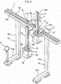
Fig. 1] Fig. 1 is a front view showing a workpiece loader device according toembodiment 1 of the present invention; - [
Fig. 2] Fig. 2 is a side view of the workpiece loader device; - [
Fig. 3] Fig. 3 is a front perpendicular view of the workpiece loader device; - [
Fig. 4] Fig. 4 is a front perpendicular view of a driving mechanism part of the workpiece loader device; - [
Fig. 5] Fig. 5 is a block diagram of a loader mechanism control part of the workpiece loader device; and - [
Fig. 6] Fig. 6 is a front view showing a spindle chuck according toembodiment 2 of the present invention. - Hereinafter, embodiments of the present invention will be described in reference to the drawings.
-
Figs. 1 to 5 are the illustrations to describe the workpiece loader device according toembodiment 1 of the present invention. - In the drawing,
reference numeral 1 denotes a workpiece loader device according toembodiment 1. Theworkpiece loader device 1 is provided with aloader mechanism 4 which moves aloader hand 2 holding a workpiece W between a workpiece storage part WS and a workpiece receiving position on a workpiece table 3 of the machine tool, and a loadermechanism control part 5 which controls theloader mechanism 4 so as to move theloader hand 2 to a predetermined workpiece receiving position. - In the workpiece table 3, a plurality of
positioning pins clamp claws - Here, in a case of
embodiment 1, the workpiece receiving position means a position where the position pins 3b, which are provided on the workpiece table, are engaged with the positioning holes W' of the workpiece W, and clamping the workpiece W becomes possible by theclamp claws - The
loader mechanism 4 has aloader beam 7 which extends in an X-axis direction (traveling direction), and acarrier 8 is mounted on theloader beam 7 so as to travel in the X-axis direction. Thecarrier 8 is driven forward and backward in the X-axis direction by anX-axis driving mechanism 9. Further, asaddle 10 is movably mounted on thecarrier 8 in a Z-axis direction (front and back direction), and thesaddle 10 is driven forward and backward in the Z-axis direction by a Z-axis driving mechanism 11. Further, ahand arm 12 is movably mounted on thesaddle 10 in a Y-axis direction (up and down direction), and thehand arm 12 is driven vertically in the Y-axis direction by a Y-axis driving mechanism 13. Theloader hand 2 is arranged in the lower end part of thehand arm 12, and theloader hand 2 is driven to open and close by a loader hand opening andclosing driving mechanism 15. - The
loader beam 7 is fixedly supported on a machine installation surface by L-shaped legs vertical side portions 14a andhorizontal side portions 14b. Anoperation panel 6 which manually operates theloader mechanism 4 is arranged in thehorizontal side portion 14b. - In
Fig. 4 , in order to simplify the structure of each of thedriving mechanisms carrier 8, thesaddle 10, and thehand arm 12 are omitted. - In the
X-axis driving mechanism 9, thecarrier 8 is movably supported in the X-axis direction through foursliders 9e byX-axis guide rails loader beam 7. Apinion gear 9c fixed in the output shaft of an X-axis drivingmotor 9b, which is mounted in thecarrier 8, meshes with arack 9c fixed in theloader beam 7. Thecarrier 8 moves forward and backward in the X-axis direction by the forward and reverse rotation of theX-axis driving motor 9b. - In the Z-
axis driving mechanism 11, thesaddle 10 is movably supported in the Z-axis direction through foursliders 11e by Z-axis guide rails carrier 8. Apinion gear 11c fixed in the output shaft of the Z-axis driving motor 11b, which is mounted in thesaddle 10, meshes with arack 11d fixed in thecarrier 8. Thesaddle 10 moves forward and backward in the Z-axis direction by the forward and reverse rotation of the Z-axis driving motor 11b. - In the Y-
axis driving mechanism 13, thehand arm 12 is movably supported in the Y-axis direction by thesaddle 10 through theslider 13e fixed in a Y-axis guide rail 13b and thesaddle 10. Apinion gear 13c fixed in the output shaft of the Y-axis driving motor 13b, which is arranged in thesaddle 10, meshes with arack 13d fixed in thehand arm 12. Thehand arm 12 moves up and down in the Y-axis direction by the forward and reverse rotation of the Y-axis driving motor 13b. - The
loader hand 2 has a pair of thegripping claws gripping claws closing driving mechanism 15. Therefore, with such configuration, it is possible to hold the workpiece W. - In the
loader mechanism 4, when an operation mode is switched to a workpiece receiving position teaching mode, which will be described later, by controlling theoperation panel 6, the operator can directly move theloader hand 2 to a predetermined position by hands. Further, theX-axis driving motor 9b, the Y-axis driving motor 13b, and the Z-axis driving motor 11b are respectively provided with an X-axis movingdirection detection sensor 16a, a Z-axis movingdirection detection sensor 16b, and a Y-axis movingdirection detection sensor 16c so as to detect a moving direction of theloader hand 2 moved by operator's hands. - In the loader
mechanism control part 5, it is possible to switch between a workpiece receiving mode and a workpiece receiving position teaching mode. In the workpiece receiving mode, theloader mechanism 4 controls theloader hand 2 to move to the predetermined workpiece receiving position. - In the workpiece receiving position teaching mode, the loader
mechanism control part 5 controls theloader mechanism 4 as described below. - Further, in the teaching mode, it is possible to switch between a moving mode by the operation device and a moving mode by operator's hands. First, prior to the process in which the operator moves the
loader hand 2 by operator's hands, in the moving mode by the operation device, the loadermechanism control part 5 controls theloader mechanism 4 to move theloader hand 2 in the vicinity of the receiving position. - When the operator switches to the moving mode by operator's hands and the
loader hand 2 is moved to the workpiece receiving position by operator's hands, the moving direction and the X, Y, Z coordinates position are detected by the X-axis, Y-axis, Z-axis moving direction detection sensors, and the detected moving direction and the X, Y, Z coordinates position are inputted to the loadermechanism control part 5. Then, the loadermechanism control part 5 controls theloader mechanism 4 to generate an assisting force in the detected moving direction of the loader hand. For example, in a case in which theloader hand 2 moves in the X-axis direction, an electric current is supplied to theX-axis driving motor 9b of theX-axis driving mechanism 9 in order to generate a driving power which equals to the friction resistance force of rack and pinion mechanisms, etc. in the moving direction. Further, regarding an assisting force of the Y-axis direction, an electric current is supplied to generate the assisting force so that it becomes possible for theloader hand 2 to be always stopped at any position in the up-and-down direction against its weight. - In the loader
mechanism control part 5, the X, Y, Z coordinates position are read due to the operator moves theloader hand 2 to the workpiece receiving position by operator's hands. At the point in which the positioning holes W' of the workpiece W are engaged with the positioning pins 3b of the workpiece table 3 and theclamp claws 3a become possible to hold the workpiece W, when the operator confirms the completion of moving process by theoperation panel 6, the X, Y, Z coordinates position of theloader hand 2 are stored as the workpiece receiving position coordinates. - In the normal workpiece loader process, the loader
mechanism control part 5 controls theloader mechanism 4 so as to position the workpiece W at the stored workpiece receiving position coordinates by theloader hand 2. - As described above, in the present embodiment, in the case in which the loader
mechanism control part 5 controls theloader mechanism 4 to move theloader hand 2 in predetermined workpiece receiving position coordinates, the position coordinates, where the operator directly moves theloader hand 2 by hands to the workpiece receiving position while visually observing the position and confirms the completion of moving, are stored as the workpiece receiving position coordinates. Therefore, there are the advantages that the teaching work can be simplified and the teaching time can be shortened in comparison with the conventional operation. - Further, prior to the process in which the operator moves the
loader hand 2 by hands, theloader mechanism 4 is controlled to move theloader hand 2 to the vicinity of the receiving position, so that the operator can complete the teaching by only moving theloader hand 2 in a short distance by hands. Therefore, the teaching time can be shortened even more. - Further, it is configured to generate the assisting force in a direction to which the operator moves the
loader hand 2 by hands, and therefore, the operator can move theloader hand 2 lightly and the teaching work can be easily performed. - Furthermore, regarding the assisting force of the Y-axis direction (up-and-down direction), the assisting force is generated to stop the
loader hand 2 at any up-and-down direction position against its weight. Therefore, in the case in which the operator moves up and down theloader hand 2 to direct the receiving position, this reduces the labor burden of the operator due to the loader hand's weight. Also, from this point, the teaching work can be facilitated. - In
embodiment 1, the X, Y, Z coordinates in the state in which the positioning pins 3b of the workpiece table 3 are engaged with the positioning holes W' of the workpiece W is defined as the workpiece receiving position coordinates, but the workpiece receiving position coordinates of the present invention are not limited to them. -
Fig. 6 is anillustration showing embodiment 2 in a case in which a workpiece is received in a chuck (clamp mechanism) 31 mounted in a spindle of a lathe. Thechuck 31 has threeclamp claws clamp claws 31a to 31c (see the solid line inFig. 6 ), it is configured to automatically adjust the position of the workpiece W to the center, which corresponds to the shaft center a of the spindle, by theclamp claws 31a to 31c (see the broken line inFig. 6 ). - In
embodiment 2, when the operator moves theloader hand 2 by hands in order to move the workpiece W in a position within the region surrounding by theclamp claws 31a to 31c of thechuck 31, and when the workpiece W is clamped by thechuck 31, theclamp claws 31a to 31c automatically adjust the shaft center a' of the workpiece W to correspond with the shaft center a of the spindle, and it is clamped. At the point in which the workpiece W is clamped, the loadermechanism control part 5 stores the X, Y, Z coordinates as the workpiece receiving position coordinates. - In
embodiment 2, at the point in which the workpiece W is moved to the position where thechuck 31 becomes possible to clamp the workpiece W, and the workpiece W is positioned and clamped by thechuck 3, the position coordinates are stored as the workpiece receiving position coordinates. Therefore, there are the advantages in which the dial gauge is not required for the teaching work in comparison with the conventional operation in which the operator controls the operation device while confirming the position of the workpiece W, which is held by the loader hand, by using the dial gauge. Further, the teaching work can be simplified and the teaching time can be shortened. -
- 1 workpiece loader device
- 2 loader hand
- 3 workpiece table (clamp mechanism)
- 4 loader mechanism
- 5 loader mechanism control part
- 16a-16c moving direction detection sensor
- 31 chuck (clamp mechanism)
- W workpiece
- WS workpiece storage part
Claims (5)
- A workpiece loader device comprising:a loader mechanism moving a loader hand, which holds a workpiece, between a workpiece storage part and a workpiece receiving position in a clamp mechanism of a machine tool; anda loader mechanism control part controlling the loader mechanism to move the loader hand to a predetermined workpiece receiving position,wherein the loader mechanism is configured to move the loader hand directly held by operator's hands to a desired position, andthe loader mechanism control part stores position coordinates when the loader hand is moved by operator's hands to the workpiece receiving position and a completion of moving is confirmed as workpiece receiving position coordinates.
- The workpiece loader device according to claim 1, wherein prior to moving the loader hand by operator's hands, the loader mechanism control part controls the loader mechanism to move the loader hand in a vicinity of the receiving position.
- The workpiece loader device according to claim 1 or claim 2, further comprising: a moving direction detection sensor detecting a moving direction of the loader hand by operator's hands, wherein the loader mechanism control part controls the loader mechanism to generate an assisting force in the detected moving direction.
- The workpiece loader device according to claim 3, wherein the loader mechanism control part controls the loader mechanism to generate the assisting force to stop the loader hand at any up-and-down direction position against a weight of the loader hand.
- The workpiece loader device according to any of claims 1 to 4, wherein the loader mechanism control part stores position coordinates of a position as the workpiece receiving position coordinates, to which the loader hand is moved by operator's hands, at which clamping the workpiece becomes possible by the clamp mechanism, and at which the workpiece is positioned and clamped by the clamp mechanism.
Applications Claiming Priority (2)
| Application Number | Priority Date | Filing Date | Title |
|---|---|---|---|
| JP2015072171A JP6619947B2 (en) | 2015-03-31 | 2015-03-31 | Work loader device |
| PCT/JP2016/056987 WO2016158218A1 (en) | 2015-03-31 | 2016-03-07 | Workpiece loader device |
Publications (4)
| Publication Number | Publication Date |
|---|---|
| EP3278939A1 true EP3278939A1 (en) | 2018-02-07 |
| EP3278939A4 EP3278939A4 (en) | 2018-04-25 |
| EP3278939B1 EP3278939B1 (en) | 2023-06-21 |
| EP3278939C0 EP3278939C0 (en) | 2023-06-21 |
Family
ID=57004233
Family Applications (1)
| Application Number | Title | Priority Date | Filing Date |
|---|---|---|---|
| EP16772102.6A Active EP3278939B1 (en) | 2015-03-31 | 2016-03-07 | Workpiece loader device |
Country Status (7)
| Country | Link |
|---|---|
| US (1) | US10300572B2 (en) |
| EP (1) | EP3278939B1 (en) |
| JP (1) | JP6619947B2 (en) |
| CN (1) | CN107428005B (en) |
| BR (1) | BR112017020764B1 (en) |
| MX (1) | MX385581B (en) |
| WO (1) | WO2016158218A1 (en) |
Cited By (1)
| Publication number | Priority date | Publication date | Assignee | Title |
|---|---|---|---|---|
| US11845184B2 (en) | 2022-04-18 | 2023-12-19 | Dextrous Robotics, Inc. | System and/or method for grasping objects |
Families Citing this family (9)
| Publication number | Priority date | Publication date | Assignee | Title |
|---|---|---|---|---|
| US10372761B2 (en) * | 2016-12-28 | 2019-08-06 | Sap Se | Auto-discovery of data lineage in large computer systems |
| CN107838789A (en) * | 2017-11-30 | 2018-03-27 | 苏州哈工易科机器人有限公司 | Automatic replacing press plate mechanism for horizontal hone grinding |
| JP7156897B2 (en) * | 2018-10-10 | 2022-10-19 | シチズン時計株式会社 | Machine Tools |
| CN109571416A (en) * | 2018-12-24 | 2019-04-05 | 重庆世玛德智能制造有限公司 | A kind of novel four axis gantry truss robot device |
| CN109927049B (en) * | 2019-04-23 | 2021-03-23 | 河北科技大学 | A gap filling manipulator |
| CN110053065A (en) * | 2019-04-25 | 2019-07-26 | 徐佳斌 | Workpiece transportation manipulator for water pump manufacture assembly |
| US10792815B1 (en) * | 2019-04-26 | 2020-10-06 | GM Global Technology Operations LLC | Perceived color harmony fixture |
| CN110561481B (en) * | 2019-10-12 | 2024-07-12 | 航天晨光股份有限公司 | Round material mechanical grabbing system |
| JP2023063894A (en) * | 2021-10-25 | 2023-05-10 | 住友重機械工業株式会社 | Holding device, robot, robot system, fitting method, robot control method, and program |
Family Cites Families (20)
| Publication number | Priority date | Publication date | Assignee | Title |
|---|---|---|---|---|
| US3218502A (en) * | 1961-03-16 | 1965-11-16 | Westinghouse Electric Corp | High power electron discharge device |
| JPS63120307A (en) * | 1986-11-10 | 1988-05-24 | Kobe Steel Ltd | Robot programming device |
| JPH0741565B2 (en) * | 1986-12-23 | 1995-05-10 | キヤノン株式会社 | Robot teaching method |
| JPH0258107A (en) * | 1988-08-24 | 1990-02-27 | Toshiba Corp | Operator support/control system at the time of teaching robot |
| JPH02279286A (en) | 1989-04-19 | 1990-11-15 | Mitsubishi Electric Corp | Positioning method for work |
| JPH03218502A (en) * | 1990-01-24 | 1991-09-26 | Murata Mach Ltd | Teaching device for robot |
| JPH0440506A (en) * | 1990-06-06 | 1992-02-10 | Murata Mach Ltd | Teaching device for robot |
| JPH0671043U (en) | 1993-03-12 | 1994-10-04 | オークマ株式会社 | Interactive input type loader controller |
| JPH0749711A (en) * | 1993-08-05 | 1995-02-21 | Brother Ind Ltd | Robot safety device |
| JPH08241109A (en) * | 1995-03-03 | 1996-09-17 | Nippon Telegr & Teleph Corp <Ntt> | Projector for setting objects and automatic working device using the same |
| US6022132A (en) * | 1996-11-15 | 2000-02-08 | Thermwood Corporation | Method and apparatus for programming a CNC machine with a probe |
| JPH11296213A (en) * | 1998-04-07 | 1999-10-29 | Fanuc Ltd | Machine device |
| JP2002187040A (en) * | 2000-12-19 | 2002-07-02 | Murata Mach Ltd | Loader control device |
| JPWO2006117840A1 (en) * | 2005-04-27 | 2008-12-18 | 平田機工株式会社 | Work transfer position teaching device and teaching method for robot |
| JP4864363B2 (en) * | 2005-07-07 | 2012-02-01 | 東芝機械株式会社 | Handling device, working device, and program |
| JP2010064158A (en) * | 2008-09-08 | 2010-03-25 | Yamazaki Mazak Corp | Machining equipment |
| JP2011206886A (en) * | 2010-03-30 | 2011-10-20 | Yaskawa Electric Corp | Device and method for controlling robot |
| JP5910491B2 (en) * | 2012-12-28 | 2016-04-27 | トヨタ自動車株式会社 | Robot arm teaching system and robot arm teaching method |
| JP2014157462A (en) * | 2013-02-15 | 2014-08-28 | Murata Mach Ltd | Loader position teaching device |
| JP6282148B2 (en) * | 2014-03-17 | 2018-02-21 | Dmg森精機株式会社 | Machine Tools |
-
2015
- 2015-03-31 JP JP2015072171A patent/JP6619947B2/en active Active
-
2016
- 2016-03-07 EP EP16772102.6A patent/EP3278939B1/en active Active
- 2016-03-07 BR BR112017020764-8A patent/BR112017020764B1/en not_active IP Right Cessation
- 2016-03-07 WO PCT/JP2016/056987 patent/WO2016158218A1/en not_active Ceased
- 2016-03-07 MX MX2017012570A patent/MX385581B/en unknown
- 2016-03-07 CN CN201680019743.0A patent/CN107428005B/en not_active Expired - Fee Related
- 2016-03-07 US US15/562,662 patent/US10300572B2/en active Active
Cited By (1)
| Publication number | Priority date | Publication date | Assignee | Title |
|---|---|---|---|---|
| US11845184B2 (en) | 2022-04-18 | 2023-12-19 | Dextrous Robotics, Inc. | System and/or method for grasping objects |
Also Published As
| Publication number | Publication date |
|---|---|
| WO2016158218A1 (en) | 2016-10-06 |
| JP6619947B2 (en) | 2019-12-11 |
| MX2017012570A (en) | 2018-01-25 |
| CN107428005B (en) | 2020-12-01 |
| BR112017020764A2 (en) | 2018-06-26 |
| MX385581B (en) | 2025-03-18 |
| US10300572B2 (en) | 2019-05-28 |
| BR112017020764B1 (en) | 2022-08-09 |
| EP3278939B1 (en) | 2023-06-21 |
| CN107428005A (en) | 2017-12-01 |
| JP2016190306A (en) | 2016-11-10 |
| EP3278939C0 (en) | 2023-06-21 |
| US20180104781A1 (en) | 2018-04-19 |
| EP3278939A4 (en) | 2018-04-25 |
Similar Documents
| Publication | Publication Date | Title |
|---|---|---|
| EP3278939B1 (en) | Workpiece loader device | |
| EP4019200A1 (en) | Production system | |
| US10780540B2 (en) | Workpiece clamp apparatus | |
| EP1992434A3 (en) | Method for controlling combined lathe apparatus, combined lathe apparatus, turning tool holder, blade position registering apparatus, and blade position detecting apparatus | |
| CN102554668B (en) | Numerical control device and method for controlling numerical control device | |
| JP6126353B2 (en) | Tool length measuring method and machine tool | |
| US20130247347A1 (en) | Section member drilling or milling machine | |
| US11453043B2 (en) | Riveting machine and method | |
| JP5994681B2 (en) | Machine tool and tool change method | |
| JP6291750B2 (en) | Machine tool and tool change method | |
| JP5732855B2 (en) | Work transfer device | |
| CN112888533B (en) | Automatic workpiece conveyor | |
| EP3112060A1 (en) | Machine tool | |
| US10875136B2 (en) | Machine tool system and clamping method | |
| EP2586564A1 (en) | Wood machining method and apparatus | |
| JP2008097192A (en) | Machine tool controller | |
| EP2644317B1 (en) | Section member drilling or milling machine | |
| JP2010069545A (en) | Numerical control type machine tool and control program used for the same | |
| US20110098843A1 (en) | Method for activating a workpiece manipulator of a machine tool | |
| JP2007188276A (en) | Loader position teaching unit | |
| CN111198537B (en) | Parameter setting device, system and parameter setting method | |
| CN113618489B (en) | Device for detecting and correcting jumping precision of numerical control machine tool and using method | |
| CN108436496A (en) | A kind of numerically-controlled machine tool body fuselage | |
| JP2011189452A (en) | Bar material cutting system | |
| EP4372497A1 (en) | Machine tool |
Legal Events
| Date | Code | Title | Description |
|---|---|---|---|
| STAA | Information on the status of an ep patent application or granted ep patent |
Free format text: STATUS: THE INTERNATIONAL PUBLICATION HAS BEEN MADE |
|
| PUAI | Public reference made under article 153(3) epc to a published international application that has entered the european phase |
Free format text: ORIGINAL CODE: 0009012 |
|
| STAA | Information on the status of an ep patent application or granted ep patent |
Free format text: STATUS: REQUEST FOR EXAMINATION WAS MADE |
|
| 17P | Request for examination filed |
Effective date: 20171027 |
|
| AK | Designated contracting states |
Kind code of ref document: A1 Designated state(s): AL AT BE BG CH CY CZ DE DK EE ES FI FR GB GR HR HU IE IS IT LI LT LU LV MC MK MT NL NO PL PT RO RS SE SI SK SM TR |
|
| AX | Request for extension of the european patent |
Extension state: BA ME |
|
| A4 | Supplementary search report drawn up and despatched |
Effective date: 20180328 |
|
| RIC1 | Information provided on ipc code assigned before grant |
Ipc: B25J 15/02 20060101ALI20180322BHEP Ipc: B25J 9/00 20060101ALI20180322BHEP Ipc: B25J 13/02 20060101ALI20180322BHEP Ipc: B25J 9/16 20060101ALI20180322BHEP Ipc: B25J 9/22 20060101AFI20180322BHEP Ipc: B23Q 7/04 20060101ALI20180322BHEP Ipc: B25J 9/02 20060101ALI20180322BHEP Ipc: B25J 13/08 20060101ALI20180322BHEP |
|
| DAV | Request for validation of the european patent (deleted) | ||
| DAX | Request for extension of the european patent (deleted) | ||
| STAA | Information on the status of an ep patent application or granted ep patent |
Free format text: STATUS: EXAMINATION IS IN PROGRESS |
|
| 17Q | First examination report despatched |
Effective date: 20210520 |
|
| GRAP | Despatch of communication of intention to grant a patent |
Free format text: ORIGINAL CODE: EPIDOSNIGR1 |
|
| STAA | Information on the status of an ep patent application or granted ep patent |
Free format text: STATUS: GRANT OF PATENT IS INTENDED |
|
| RIC1 | Information provided on ipc code assigned before grant |
Ipc: G05B 19/423 20060101ALI20230217BHEP Ipc: B23Q 1/62 20060101ALI20230217BHEP Ipc: B25J 15/02 20060101ALI20230217BHEP Ipc: B25J 13/08 20060101ALI20230217BHEP Ipc: B25J 13/02 20060101ALI20230217BHEP Ipc: B25J 9/16 20060101ALI20230217BHEP Ipc: B25J 9/00 20060101ALI20230217BHEP Ipc: B25J 9/02 20060101ALI20230217BHEP Ipc: B23Q 7/04 20060101ALI20230217BHEP Ipc: B25J 9/22 20060101AFI20230217BHEP |
|
| INTG | Intention to grant announced |
Effective date: 20230315 |
|
| GRAS | Grant fee paid |
Free format text: ORIGINAL CODE: EPIDOSNIGR3 |
|
| GRAA | (expected) grant |
Free format text: ORIGINAL CODE: 0009210 |
|
| STAA | Information on the status of an ep patent application or granted ep patent |
Free format text: STATUS: THE PATENT HAS BEEN GRANTED |
|
| AK | Designated contracting states |
Kind code of ref document: B1 Designated state(s): AL AT BE BG CH CY CZ DE DK EE ES FI FR GB GR HR HU IE IS IT LI LT LU LV MC MK MT NL NO PL PT RO RS SE SI SK SM TR |
|
| REG | Reference to a national code |
Ref country code: CH Ref legal event code: EP |
|
| REG | Reference to a national code |
Ref country code: DE Ref legal event code: R096 Ref document number: 602016080474 Country of ref document: DE |
|
| REG | Reference to a national code |
Ref country code: AT Ref legal event code: REF Ref document number: 1580583 Country of ref document: AT Kind code of ref document: T Effective date: 20230715 |
|
| REG | Reference to a national code |
Ref country code: IE Ref legal event code: FG4D |
|
| U01 | Request for unitary effect filed |
Effective date: 20230622 |
|
| U07 | Unitary effect registered |
Designated state(s): AT BE BG DE DK EE FI FR IT LT LU LV MT NL PT SE SI Effective date: 20230629 |
|
| REG | Reference to a national code |
Ref country code: LT Ref legal event code: MG9D |
|
| PG25 | Lapsed in a contracting state [announced via postgrant information from national office to epo] |
Ref country code: NO Free format text: LAPSE BECAUSE OF FAILURE TO SUBMIT A TRANSLATION OF THE DESCRIPTION OR TO PAY THE FEE WITHIN THE PRESCRIBED TIME-LIMIT Effective date: 20230921 |
|
| PG25 | Lapsed in a contracting state [announced via postgrant information from national office to epo] |
Ref country code: RS Free format text: LAPSE BECAUSE OF FAILURE TO SUBMIT A TRANSLATION OF THE DESCRIPTION OR TO PAY THE FEE WITHIN THE PRESCRIBED TIME-LIMIT Effective date: 20230621 Ref country code: HR Free format text: LAPSE BECAUSE OF FAILURE TO SUBMIT A TRANSLATION OF THE DESCRIPTION OR TO PAY THE FEE WITHIN THE PRESCRIBED TIME-LIMIT Effective date: 20230621 Ref country code: GR Free format text: LAPSE BECAUSE OF FAILURE TO SUBMIT A TRANSLATION OF THE DESCRIPTION OR TO PAY THE FEE WITHIN THE PRESCRIBED TIME-LIMIT Effective date: 20230922 |
|
| PG25 | Lapsed in a contracting state [announced via postgrant information from national office to epo] |
Ref country code: SK Free format text: LAPSE BECAUSE OF FAILURE TO SUBMIT A TRANSLATION OF THE DESCRIPTION OR TO PAY THE FEE WITHIN THE PRESCRIBED TIME-LIMIT Effective date: 20230621 |
|
| PG25 | Lapsed in a contracting state [announced via postgrant information from national office to epo] |
Ref country code: ES Free format text: LAPSE BECAUSE OF FAILURE TO SUBMIT A TRANSLATION OF THE DESCRIPTION OR TO PAY THE FEE WITHIN THE PRESCRIBED TIME-LIMIT Effective date: 20230621 |
|
| PG25 | Lapsed in a contracting state [announced via postgrant information from national office to epo] |
Ref country code: IS Free format text: LAPSE BECAUSE OF FAILURE TO SUBMIT A TRANSLATION OF THE DESCRIPTION OR TO PAY THE FEE WITHIN THE PRESCRIBED TIME-LIMIT Effective date: 20231021 |
|
| PG25 | Lapsed in a contracting state [announced via postgrant information from national office to epo] |
Ref country code: SM Free format text: LAPSE BECAUSE OF FAILURE TO SUBMIT A TRANSLATION OF THE DESCRIPTION OR TO PAY THE FEE WITHIN THE PRESCRIBED TIME-LIMIT Effective date: 20230621 Ref country code: SK Free format text: LAPSE BECAUSE OF FAILURE TO SUBMIT A TRANSLATION OF THE DESCRIPTION OR TO PAY THE FEE WITHIN THE PRESCRIBED TIME-LIMIT Effective date: 20230621 Ref country code: RO Free format text: LAPSE BECAUSE OF FAILURE TO SUBMIT A TRANSLATION OF THE DESCRIPTION OR TO PAY THE FEE WITHIN THE PRESCRIBED TIME-LIMIT Effective date: 20230621 Ref country code: IS Free format text: LAPSE BECAUSE OF FAILURE TO SUBMIT A TRANSLATION OF THE DESCRIPTION OR TO PAY THE FEE WITHIN THE PRESCRIBED TIME-LIMIT Effective date: 20231021 Ref country code: ES Free format text: LAPSE BECAUSE OF FAILURE TO SUBMIT A TRANSLATION OF THE DESCRIPTION OR TO PAY THE FEE WITHIN THE PRESCRIBED TIME-LIMIT Effective date: 20230621 Ref country code: CZ Free format text: LAPSE BECAUSE OF FAILURE TO SUBMIT A TRANSLATION OF THE DESCRIPTION OR TO PAY THE FEE WITHIN THE PRESCRIBED TIME-LIMIT Effective date: 20230621 |
|
| PG25 | Lapsed in a contracting state [announced via postgrant information from national office to epo] |
Ref country code: PL Free format text: LAPSE BECAUSE OF FAILURE TO SUBMIT A TRANSLATION OF THE DESCRIPTION OR TO PAY THE FEE WITHIN THE PRESCRIBED TIME-LIMIT Effective date: 20230621 |
|
| REG | Reference to a national code |
Ref country code: DE Ref legal event code: R097 Ref document number: 602016080474 Country of ref document: DE |
|
| U20 | Renewal fee for the european patent with unitary effect paid |
Year of fee payment: 9 Effective date: 20240314 |
|
| PLBE | No opposition filed within time limit |
Free format text: ORIGINAL CODE: 0009261 |
|
| STAA | Information on the status of an ep patent application or granted ep patent |
Free format text: STATUS: NO OPPOSITION FILED WITHIN TIME LIMIT |
|
| 26N | No opposition filed |
Effective date: 20240322 |
|
| REG | Reference to a national code |
Ref country code: CH Ref legal event code: PL |
|
| PG25 | Lapsed in a contracting state [announced via postgrant information from national office to epo] |
Ref country code: MC Free format text: LAPSE BECAUSE OF FAILURE TO SUBMIT A TRANSLATION OF THE DESCRIPTION OR TO PAY THE FEE WITHIN THE PRESCRIBED TIME-LIMIT Effective date: 20230621 |
|
| GBPC | Gb: european patent ceased through non-payment of renewal fee |
Effective date: 20240307 |
|
| PG25 | Lapsed in a contracting state [announced via postgrant information from national office to epo] |
Ref country code: MC Free format text: LAPSE BECAUSE OF FAILURE TO SUBMIT A TRANSLATION OF THE DESCRIPTION OR TO PAY THE FEE WITHIN THE PRESCRIBED TIME-LIMIT Effective date: 20230621 |
|
| PG25 | Lapsed in a contracting state [announced via postgrant information from national office to epo] |
Ref country code: GB Free format text: LAPSE BECAUSE OF NON-PAYMENT OF DUE FEES Effective date: 20240307 |
|
| PG25 | Lapsed in a contracting state [announced via postgrant information from national office to epo] |
Ref country code: IE Free format text: LAPSE BECAUSE OF NON-PAYMENT OF DUE FEES Effective date: 20240307 |
|
| PG25 | Lapsed in a contracting state [announced via postgrant information from national office to epo] |
Ref country code: IE Free format text: LAPSE BECAUSE OF NON-PAYMENT OF DUE FEES Effective date: 20240307 Ref country code: GB Free format text: LAPSE BECAUSE OF NON-PAYMENT OF DUE FEES Effective date: 20240307 Ref country code: CH Free format text: LAPSE BECAUSE OF NON-PAYMENT OF DUE FEES Effective date: 20240331 |
|
| PG25 | Lapsed in a contracting state [announced via postgrant information from national office to epo] |
Ref country code: CY Free format text: LAPSE BECAUSE OF FAILURE TO SUBMIT A TRANSLATION OF THE DESCRIPTION OR TO PAY THE FEE WITHIN THE PRESCRIBED TIME-LIMIT; INVALID AB INITIO Effective date: 20160307 |
|
| PG25 | Lapsed in a contracting state [announced via postgrant information from national office to epo] |
Ref country code: HU Free format text: LAPSE BECAUSE OF FAILURE TO SUBMIT A TRANSLATION OF THE DESCRIPTION OR TO PAY THE FEE WITHIN THE PRESCRIBED TIME-LIMIT; INVALID AB INITIO Effective date: 20160307 |
|
| U90 | Renewal fees not paid: noting of loss of rights |
Free format text: RENEWAL FEE NOT PAID FOR YEAR 10 Effective date: 20251017 |
|
| PG25 | Lapsed in a contracting state [announced via postgrant information from national office to epo] |
Ref country code: TR Free format text: LAPSE BECAUSE OF FAILURE TO SUBMIT A TRANSLATION OF THE DESCRIPTION OR TO PAY THE FEE WITHIN THE PRESCRIBED TIME-LIMIT Effective date: 20230621 |
|
| U93 | Unitary patent lapsed |
Free format text: RENEWAL FEE NOT PAID Effective date: 20250331 |