EP3278912A1 - Roughing end mill - Google Patents
Roughing end mill Download PDFInfo
- Publication number
- EP3278912A1 EP3278912A1 EP16772483.0A EP16772483A EP3278912A1 EP 3278912 A1 EP3278912 A1 EP 3278912A1 EP 16772483 A EP16772483 A EP 16772483A EP 3278912 A1 EP3278912 A1 EP 3278912A1
- Authority
- EP
- European Patent Office
- Prior art keywords
- end mill
- outer peripheral
- cutting edge
- cutting edges
- main body
- Prior art date
- Legal status (The legal status is an assumption and is not a legal conclusion. Google has not performed a legal analysis and makes no representation as to the accuracy of the status listed.)
- Withdrawn
Links
- 238000005520 cutting process Methods 0.000 claims abstract description 365
- 230000002093 peripheral effect Effects 0.000 claims abstract description 165
- 230000000052 comparative effect Effects 0.000 description 9
- 230000010363 phase shift Effects 0.000 description 8
- 238000003754 machining Methods 0.000 description 7
- 230000001154 acute effect Effects 0.000 description 2
- 238000007599 discharging Methods 0.000 description 2
- 230000000694 effects Effects 0.000 description 2
- 230000012447 hatching Effects 0.000 description 2
- 239000000463 material Substances 0.000 description 2
- 239000007787 solid Substances 0.000 description 2
- 230000001960 triggered effect Effects 0.000 description 2
- 238000005219 brazing Methods 0.000 description 1
- 230000007423 decrease Effects 0.000 description 1
- 230000006866 deterioration Effects 0.000 description 1
Images



Classifications
-
- B—PERFORMING OPERATIONS; TRANSPORTING
- B23—MACHINE TOOLS; METAL-WORKING NOT OTHERWISE PROVIDED FOR
- B23C—MILLING
- B23C5/00—Milling-cutters
- B23C5/003—Milling-cutters with vibration suppressing means
-
- B—PERFORMING OPERATIONS; TRANSPORTING
- B23—MACHINE TOOLS; METAL-WORKING NOT OTHERWISE PROVIDED FOR
- B23C—MILLING
- B23C5/00—Milling-cutters
- B23C5/02—Milling-cutters characterised by the shape of the cutter
- B23C5/06—Face-milling cutters, i.e. having only or primarily a substantially flat cutting surface
-
- B—PERFORMING OPERATIONS; TRANSPORTING
- B23—MACHINE TOOLS; METAL-WORKING NOT OTHERWISE PROVIDED FOR
- B23C—MILLING
- B23C5/00—Milling-cutters
- B23C5/006—Details of the milling cutter body
-
- B—PERFORMING OPERATIONS; TRANSPORTING
- B23—MACHINE TOOLS; METAL-WORKING NOT OTHERWISE PROVIDED FOR
- B23C—MILLING
- B23C5/00—Milling-cutters
- B23C5/02—Milling-cutters characterised by the shape of the cutter
- B23C5/10—Shank-type cutters, i.e. with an integral shaft
-
- B—PERFORMING OPERATIONS; TRANSPORTING
- B23—MACHINE TOOLS; METAL-WORKING NOT OTHERWISE PROVIDED FOR
- B23C—MILLING
- B23C2210/00—Details of milling cutters
- B23C2210/08—Side or top views of the cutting edge
- B23C2210/088—Cutting edges with a wave form
-
- B—PERFORMING OPERATIONS; TRANSPORTING
- B23—MACHINE TOOLS; METAL-WORKING NOT OTHERWISE PROVIDED FOR
- B23C—MILLING
- B23C2210/00—Details of milling cutters
- B23C2210/20—Number of cutting edges
- B23C2210/203—Number of cutting edges four
-
- B—PERFORMING OPERATIONS; TRANSPORTING
- B23—MACHINE TOOLS; METAL-WORKING NOT OTHERWISE PROVIDED FOR
- B23C—MILLING
- B23C2210/00—Details of milling cutters
- B23C2210/24—Overall form of the milling cutter
-
- B—PERFORMING OPERATIONS; TRANSPORTING
- B23—MACHINE TOOLS; METAL-WORKING NOT OTHERWISE PROVIDED FOR
- B23C—MILLING
- B23C2210/00—Details of milling cutters
- B23C2210/28—Arrangement of teeth
- B23C2210/287—Cutting edges arranged at different axial positions or having different lengths in the axial direction
-
- B—PERFORMING OPERATIONS; TRANSPORTING
- B23—MACHINE TOOLS; METAL-WORKING NOT OTHERWISE PROVIDED FOR
- B23C—MILLING
- B23C2220/00—Details of milling processes
- B23C2220/60—Roughing
-
- B—PERFORMING OPERATIONS; TRANSPORTING
- B23—MACHINE TOOLS; METAL-WORKING NOT OTHERWISE PROVIDED FOR
- B23C—MILLING
- B23C2250/00—Compensating adverse effects during milling
- B23C2250/16—Damping vibrations
Definitions
- the present invention relates to a roughing end mill drill, in which outer peripheral cutting edges are provided on the outer circumference of the tip part of the end mill main body rotated about the axis.
- the outer peripheral cutting edge has a waveform cutting edge that is concaved and convexed in the radial direction of the end mill main body viewed from the end mill rotation direction.
- Patent Literature 1 As an example of a roughing end mill, one in Patent Literature 1 (PTL 1) is disclosed.
- PTL 1 Patent Literature 1
- multiple grooves having a predetermined twist angle are formed on the outer circumference of the main body, and edge parts (outer peripheral cutting edges), which have cutting edges in a waveform (waveform edge) along the grooves, are provided.
- edge parts outer peripheral cutting edges
- fragmented chips are formed by the surrounding of the peak of the waveform cutting edge, which are convexed to the outer circumference side of the end mill main body, by positioning the phases of the waveform cutting edges in a shifted manner toward the rear or tip end side of the end mill main body between the outer peripheral cutting edges adjacent in the radial direction of the end mill main body. Accordingly, the cutting resistance is reduced in roughing of a workpiece.
- Patent Literature 1 Japanese Unexamined Patent Application, First Publication No. S63-034010 (A )
- phase shift of the waveform cutting edges in such a roughing end mill is configured in such a way that the phase of the waveform cutting edge sequentially shifts to the rear (or tip) end side of the end mill main body within one pitch of the waveform cutting edge from the reference outer circumference cutting edge toward the side opposite to the end mill rotation direction, thereby to return to the original reference outer circumference cutting edge, as described in the above-mentioned PTL 1.
- the phase of the waveform cutting edge shifts at an equal interval from the reference outer peripheral cutting edge toward the rear or tip end side of the end mill main body.
- the shape and dimension of the cross section of the chip formed by each of the waveform cutting edges in roughing are the same.
- the chatter vibration due to resonance of the end mill main body are more likely to occur since the impacts when the waveform cutting edges are cut into the workpiece are the same.
- the cutting load to the waveform cutting edges is reduced by adjusting the shift amount of the phase of the waveform cutting edges for the machining efficiency to be improved.
- there is no difference in the sense that the shapes of the cross sections of the chips formed are the same.
- the present invention has been made under such circumstances.
- the purpose of the present invention is to provide a roughing end mill capable of preventing the chatter vibration from occurring in the above-described roughing end mill provided with the outer peripheral cutting edges including the waveform cutting edges.
- a roughing end mill including:
- the phase of the reference outer peripheral cutting edge returns to the original phase of the reference outer peripheral cutting edge by: being sequentially shifted twice from the reference outer peripheral cutting edge toward the rear end side of the end mill main body in the direction opposite to the end mill rotation direction in two outer peripheral cutting edges; then, the phases of the subsequent outer peripheral cutting edges being shifted once toward the tip end side of the end mill main body; and then, the phases of the further subsequent outer peripheral cutting edges being further shifted once to the tip end side of the end mill man body when the outer peripheral cutting edge goes around to return to the original reference outer peripheral cutting edge.
- the impacts when the waveform cutting edges cut into the workpiece are loaded on the same times of 2 toward the rear end side and the tip end side of the end mill main body when the end mill main body makes one round between the reference outer peripheral cutting edges.
- vibrations formed due to these impacts can be cancelled each other; and occurrence of the chatter vibration because of the end mill main body resonating by these impacts can be prevented. Accordingly, the machined surface accuracy and machining efficiency can be improved, and damages of the end mill main body can be prevented.
- the waveform cutting edges in which the phases are shifted to the rear end side of the end mill main body toward the side opposite to the end mill rotation direction in multiple times and the waveform cutting edges in which the phases are shifted to the tip end side of the end mill main body in multiple times toward the side opposite to the end mill rotation direction it is possible for the shape and the area of the cross sections of the chips formed by the waveform cutting edges to be different each other. Therefore, the impacts when these waveform cutting edges cut into the workpiece become different each other. Accordingly, the vibration due to these impacts becomes even harder to resonate; and the occurrence of the chatter vibration can be prevented even more reliably.
- the end cutting edge extending from the tip of the outer peripheral cutting edge to the inner peripheral side is formed at the end of the end mill main body.
- the end cutting edge extends along the plane perpendicular to the axis of the end mill main body
- the waveform cutting edge crosses with the end cutting edge at the part that is concaved to the inner peripheral side toward the rear end side of the end mill main body.
- a tip cutting edge which connects to a peak of the waveform cutting edge disposed in a most distal end of the end mill main body, is provided on a tip end part of each of the outer peripheral cutting edges, a rotation locus about the axis of tip cutting edges being positioned on an identical cylindrical surface centered on the axis in order to secure strength by having the cross angle be a substantially right angle by crossing the tip cutting edge with the end cutting edge.
- the roughing end mill of the present invention unlike the above-described normal roughing end mill, in the roughing end mill, which is an aspect of the present invention, (hereinafter referred as "the roughing end mill of the present invention"), even in the case where the tip cutting edge is provided on the tip end part of the outer peripheral cutting edge, the cutting edge length of the tip cutting edge is sequentially lengthened in multiple times in the outer peripheral cutting edge from the reference outer peripheral cutting edge toward the side opposite to the end mill rotation direction; and sequentially shortened in the same times to return to the level in the reference outer peripheral cutting edge. Therefore, the removal allowance of the outer peripheral cutting edge having the tip cutting edge with the longest cutting edge does not become too large. Accordingly, the occurrence of fracture can be prevented. In addition, the rapid change of the cutting load at the tip end part of the end mill main body because of the removal allowance being changed greatly, can be prevented. Accordingly, the occurrence of the chatter vibration can be prevented more reliably.
- the chatter vibration can be prevented by cancelling vibration due to these impacts each other; the machining accuracy and the machining efficiency can be improved; and the service life of the end mill can be lengthened.
- FIGS. 1 to 4 show one embodiment of the present invention.
- the end mill main body 1 is formed in a substantially cylindrical shape having an outer shape centered on the axis O by a hard material such as a cemented carbide or the like, and the end mill main body 1 is provided at the rear end side (upper right side in FIG. 1 , right side in FIGS. 2 and 4 ).
- the read end part of the end mill main body 1 is the shank portion 2 that remains in a columnar shape, and the part on the tip end side (the lower left side in FIG. 1 , the left side in FIGS. 2 and 4 ) is the cutting edge portion 3.
- the chip discharge flutes 4 extending from the tip end to the rear end side of the end mill main body 1 is formed on the outer circumference of the cutting blade portion 3.
- the outer peripheral cutting edges 6 are formed on the outer side ridges of walls of the chip discharge flutes 4 facing the direction of the end mill rotation direction T.
- the walls of the chip discharging flutes 4 facing the direction of the end mill rotation direction T are the rake faces of the outer peripheral cutting edges 6.
- the outer circumference surface of the cutting edge part 3 crossing the above-described rake face is the outer peripheral flank faces 5 of the outer peripheral cutting edges 6.
- four cutting chip discharge flutes 4 are formed on the cutting edge part 3 spaced apart in the circumferential direction with an interval.
- the outer peripheral cutting edges 6,4 of them are formed spaced apart in the circumferential direction with an interval, similarly.
- the gashes 7 having a substantially V-shaped concave groove shape are formed at the tip portion of each of the chip discharge flutes 4, and the end cutting edges 8 are formed on the tip end edges of the wall surfaces of these gashes 7 facing the end mill rotation direction T in such a way that the end cutting edge 8 extends from the tip end of each outer peripheral cutting edge 6 to the inner peripheral side.
- the wall surfaces of the gashes 7 are the rake faces of the end cutting edges 8.
- the end cutting edge 8 extends substantially along the plane orthogonal to the axis O to be the square-type solid roughing end mill, in which the end cutting edge 8 crosses with the after-mentioned tip cutting edge, which is formed in the tip end part of the outer peripheral cutting edge 6, in a substantially right angle.
- Each chip discharge flute 4 is formed so as to twist to the rear side in the end mill rotation direction T about the axis O from the tip end of the end mill main body 1 toward the rear end side.
- each of the outer peripheral cutting edges 6 is formed in a spiral shape that twists toward the rear side in the end mill rotation direction T about the axis O from the tip end of the end mill main body 1 to the rear end side in a similar manner.
- the twist angles of the spirals formed by the four outer peripheral cutting edges 6 are formed to be equal to each other, and the circumferential intervals of the four outer peripheral cutting edges 6 are also formed to be equal to each other.
- outer peripheral flank faces 5 of the outer peripheral cutting edges 6 are formed in such a way that concave and convex are formed in the radial direction (inner and outer circumferential direction of the end mill main body 1) in the part from the location slightly apart from the tip end of the end mill main body 1 to the rear end side of the cutting edge part 3. Therefore, in this portion, the outer peripheral cutting edges 6 are also formed in the waveform concaved and convexed in the radial direction with respect to the axis O of the end mill main body 1 as viewed from the end mill rotation direction T as shown in FIG. 4 ; and this portion is defined as the waveform cutting edge 9 in the present embodiment.
- the waveform of these waveform cutting edges 9 is formed in the shape in which the convexed arc, which is convexed toward the outer circumferential side of the end mill main body 1; and the concaved arc, which is concaved toward the inner circumferential side of the end mill main body 1, are alternatively connected continuously with a constant pitch (pitch P) as viewed from the end mill rotation direction as shown in FIG 4 .
- the shape and the size of the waveform formed by each waveform cutting edge 9, which are the period and the amplitude thereof, is set equally.
- the phase of the waveform is shifted in the direction of the axis O between the outer peripheral cutting edges 6 adjacent in the circumferential direction.
- the tip cutting edge 10 which connects to the peak toward the outer circumferential side in the waveform in the most distal end of the end mill main body 1 among the waveform cutting edges 9 of each outer peripheral cutting edge 6 (the location where the waveform cutting edge 9 starts concaving at first to the inner circumferential side toward the rear end side of the end mill main body 1); and the rotation locus about the axis O thereof are located on the identical cylindrical surface centered on the axis O, is provided to be crossed with the end cutting edge 8. Therefore, the length of the tip cutting edges 10 of the respective outer peripheral cutting edges 6 is different depending on the phase shift of the waveform cutting edge 9.
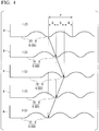
- the above-described waveform cutting edges 9 of the outer peripheral cutting edges 6 have one or more parts, in which phases of the waveform cutting edges 9 are sequentially shifted multiple times toward a rear end side of the end mill main body 1, and then shifted the same multiple times toward a tip end side of the end mill main body 1, while a reference outer peripheral cutting edge 6A goes around once on a side opposite to the end mill rotation direction T and returns to a position of the reference outer peripheral cutting edge 6A as shown in FIG. 4 by the arrows.
- the outer peripheral cutting edge 6 is defined as the reference first outer peripheral cutting edge 6A when the peak of the waveform is connected to the tip cutting edge 10 located on the most distal side of the end mill main body 1 with respect to each waveform cutting edge 9 as shown in FIG. 4 , the phase of the waveform cutting edge 9 of the subsequent second outer peripheral cutting edge 6B, which is adjacent to the reference first outer peripheral cutting edge 6A in the side opposite to the end mill rotation direction T, is shifted one step toward the rear end side of the end mill main body 1.
- phase of the waveform cutting edge 9 of the further subsequent third outer peripheral cutting edge 6C which is adjacent to the second outer peripheral cutting edge 6B in the side opposite to the end mill rotation direction T, is further shifted one more step toward the rear end side of the end mill main body 1.
- the phase of the waveform cutting edge 9 of the fourth outer peripheral cutting edge 6D which is adjacent to the third outer peripheral cutting edge 6C in the side opposite to the end mill rotation direction T, is further shifted one step toward the tip end side of the end mill main body 1 in reverse.
- the phase of the waveform cutting edge 9 of the first reference outer peripheral cutting edge 6A which is adjacent to the fourth inner peripheral cutting edge 6D in the side opposite to the end mill rotation direction T, is further shifted one more step toward the tip end side of the end mill main body 1.
- the amounts of the phase shift Q of the waveform cutting edges 9 of the first to the fourth outer peripheral cutting edges 6A to 6D, each of which is adjacent to one of them in the side opposite to the end mill rotation direction T, are the same. Therefore, the amount of the phase shift Q is set to 1/3 of the pitch P in one waveform cutting edge 9 in the present embodiment; and the phases of the waveform cutting edges 9 of the second and the fourth outer peripheral cutting edges 6B and 6D match.
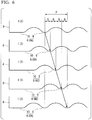
- FIG. 6 ; and the after-mentioned FIG. 7 and FIG 8(a) show Comparative Examples to embodiments of the present invention.
- the shape and the dimension of each outer peripheral cutting edge 6 are set in the same ways as in the embodiment of the present invention; and the same reference sings as in the embodiment of the present invention are placed to the common parts for explanation.
- the amount of the phase shift Q of the waveform cutting edges 9 of the first to the fourth outer peripheral cutting edges 6A to 6D, each of which is adjacent to one of them in the side opposite to the end mill rotation direction T becomes 1/4 of the pitch P of the one waveform cutting edge 9 as shown in FIG. 6 .
- the impacts are loaded toward the rear end side of the end mill main body 1 in two cuttings when the waveform cutting edges 9 of the second and the third outer peripheral cutting edges 6B, 6C, which are continuous from the reference first outer peripheral cutting edge 6A in the side opposite to the end mill rotation direction T, are cut into the workpiece as in cutting in Comparative Example.
- the impacts in two cuttings when the waveform cutting edges 9 of the fourth outer peripheral cutting edge 6D and the original reference first outer peripheral cutting edge 6A, which are continuous from the third outer peripheral cutting edge 6C in the side opposite to the end mill rotation direction T, are cut into the workpiece subsequently, are loaded toward the tip end side of the end mill main body in reverse to Comparative Example as shown in FIG 4 by the arrows.
- the impacts are loaded: twice toward the rear end side of the end mill main body 1; and in the same time of 2 toward the tip end side of the end mill main body 1 when the waveform cutting edges 9 of the outer peripheral cutting edges 6 are cut into the workpiece while the end mill main body 1 is rotated in one round, the occurrence of: the resonance of the end mill main body due to these impacts; and the chatter vibration can be prevented by cancelling out these impacts each other. Because of this, according to the roughing end mill in the above-described configuration, deterioration of the surface processing accuracy due to the chatter vibration; reduction of the machining efficiency by being unable to increase the feed in cutting; and breaking due to the end mill main body 1 being hit to the machined surface, can be prevented.
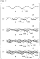
- FIGS. 5 and 7 show the cross sections in order along the feed direction F of the chips formed by the waveform cutting edges 9 when each of the outer peripheral cutting edges 6 of the roughing end mills of the present embodiment and the normal roughing end mill of Comparative Example shown in FIG. 6 are cut into the workpiece W, respectively.
- the dotted parts and the hatched parts correspond to the chips by the waveform cutting edge 9 of the outer peripheral cutting edge 6 cut into the workpiece W and the chips by the waveform cutting edge 9 of the outer peripheral cutting edge 6 in previous cutting, respectively.
- the cross sections of the chips are sequentially increased in the shape of fans as shown in FIGS. 7 (a) to 7(d) as the outer peripheral cutting edges 6 being cut into the workpiece W.
- the cross section reaches to the maximum as shown in FIG. 7 (e) .
- the chips having the same shape and the same cross section are formed continuously. Therefore, the extents of the impacts loaded on each of the waveform cutting edges 9 after that are the same.
- the cross sectional area of the chips formed in the roughing end mill of the present embodiment increase sequentially in the shape of fans substantially the same as Comparative Example as shown in FIGS. 5 (a) to 5(c) until the waveform cutting edges 9 of the first to the third outer peripheral cutting edges 6A to 6C are cut into the workpiece W.
- the waveform cutting edge 9 of the fourth outer peripheral cutting edge 6D which is subsequent to the third outer peripheral cutting edge 6C, cut the machined surface having been cut by the second outer peripheral cutting edge 6B.
- the chips formed in this step are in the thin arc shape; and the cross sectional area is reduced as shown in FIG. 5 (d) .
- the chips formed by the waveform cutting edge 9 of the first outer peripheral cutting edge 6A, which is subsequent to the fourth outer peripheral cutting edge 6D, after the end mill main body 1 rotated in one round are formed in the fan shape thicker than the chips formed by the waveform cutting edge 9 of the fourth outer peripheral cutting edge 6D and with a larger cross sectional area as shown in FIG. 5 (e) .
- the extents of the impacts differ in the waveform cutting edges 9 of the outer peripheral cutting edges 6 adjacent to the side opposite to the end mill rotation direction T. Because of this, the occurrence of the chatter vibration to the end mill main body 1 by vibration resonance due to these impacts can be prevented more reliably; the processing accuracy and processing efficiency can be further improved; and a roughing end mill having a long service life can be provided.
- the tip cutting edge 10 which is connected to the peak of the waveform cutting edge 9 in the most distal end of the end mill main body, is provided to the tip end part of the outer peripheral cutting edge 6 in the present embodiment.
- the rotation locus of the tip cutting edges 10 about the axis O of tip cutting edges 10 are located on the identical cylindrical surface centered on the axis O. Since the tip cutting edge 10 crosses to the end cutting edge 8, the cross angle between the end cutting edge 8 and the outer peripheral cutting edge 6 becomes a substantially right angle.
- the tip cutting edge 10 is formed at the tip end part of the outer peripheral cutting edge 6 to be connected to the peak of the most distal convex portion of the waveform cutting edge 9, for example, in the normal roughing end mill of the Comparative Example shown in FIG. 6 , the cutting edge lengths of the tip cutting edges 10 are elongated from the outer peripheral cutting edge 6, the most distal convex portion of which is located in the most distal end side of the end mill main body 1, toward the outer peripheral cutting edge 6 on the side opposite to the end mill rotation direction as shown in FIG. 6 .
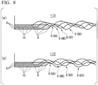
- the removal allowance by the tip cutting edges 10 of the outer peripheral cutting edges 6 and the vicinity of the peak of the mostly distal convex portion of the waveform cutting edges 9 connected to the tip cutting edges 10 on the workpiece W is minimum in the outer peripheral cutting edge 6, in which the mostly distal convex portion is located in the most distal end side of the end mill main body 1 as shown in FIG. 8 (a) by hatching. Then, it is sequentially increased toward the outer peripheral cutting edge 6 on the side opposite to the end mill rotation direction.
- the removal allowances change from the minimum to the maximum suddenly in cutting of the workpiece by the outer peripheral cutting edge 6 with the longest tip cutting edge 10 after cutting by the outer peripheral cutting edge with the shortest tip cutting edge 10.
- the removal allowances change from the maximum to the minimum suddenly in cutting of the workpiece by the outer peripheral cutting edge 6 with the shortest tip cutting edge 10 after cutting by the outer peripheral cutting edge with the longest tip cutting edge 10 as shown at the bottom in FIG. 8 (a) .
- the cutting load from the tip cutting edges 10 to the tip end part of the end mill main body 1 suddenly changes.
- the sudden change causes the occurrence of the vibration.
- the cutting edge length of the tip cutting edge 10 is sequentially lengthened in multiple times (twice) in the second and the third outer peripheral cutting edges 6B, 6C in the order from the reference first outer peripheral cutting edge 6A toward the side opposite to the end mill rotation direction T as shown in FIG.
- the removal allowance on the workpiece W by the tip cutting edges 10 of the outer peripheral cutting edges 6 and the vicinity of the peak of the most distal convex portion of the waveform cutting edges 9 connected to the tip cutting edges 10 sequentially increases and then sequentially decreases as shown in FIG. 8 (b) by hatchings, while the reference outer peripheral cutting edge 6A goes around once on the side opposite to the end mill rotation direction T and returns to the original position of the reference outer peripheral cutting edge 6A.
- Such two cutting modes are repeated alternately by the rotation of the end mill main body 1.
- the number of the peripheral cutting edges 6 is the minimum of four.
- the phase of the waveform cutting edge 9 shifts twice toward the rear end side of the end mill main body 1, and then, shifts twice toward the tip end side of the end mill main body 1, while the reference outer peripheral cutting edge 6A goes around once on the side opposite to the end mill rotation direction T and returns to the original position of the reference outer peripheral cutting edge 6A.
- the number of the outer peripheral cutting edges 6 may be set to 6, for example.
- the number of shifts toward the rear and tip ends of the end mill main body 1 may be set to a multi-number higher than 2, such as 3 times toward the rear end of the end mill main body 1, and then, 3 times toward the tip end side, while the reference outer peripheral cutting edge 6A goes around once on the side opposite to the end mill rotation direction T and returns to the original position of the reference outer peripheral cutting edge 6A.
- the amount of the phase shift Q of the waveform cutting edges 9 of the adjacent outer peripheral cutting edges 6 is set to the value obtained by dividing the one pitch P of the waveform cutting edge 9 by the number of shift plus 1.
- the maximum amount of the phase shift Q is P/3, where the number of shift is 2.
- the waveform cutting edges of the outer peripheral cutting edges have one or more parts, in which phases of the waveform cutting edges are sequentially shifted multiple times toward a rear end side of the end mill main body, and then shifted the same multiple times toward a tip end side of the end mill main body, while a reference outer peripheral cutting edge goes around once on a side opposite to the end mill rotation direction and returns to a position of the reference outer peripheral cutting edge.
- the waveform cutting edges of the outer peripheral cutting edges have one or more parts, in which phases of the waveform cutting edges are sequentially shifted multiple times toward a tip end side of the end mill main body, and then shifted the same multiple times toward a rear end side of the end mill main body.
- the phases of the waveform cutting edges are shifted once toward the rear tip side of the end mill main body to the side opposite to the end mill rotation direction, and then shifted once toward the tip end, the phases of the waveform are shifted alternately in every step, rather making it easier for the vibration to occur.
- the technical effect of the present invention cannot be obtained in this case.
- the present invention is applied to the solid roughing end mill with the outer peripheral cutting edges 6 being directly formed on the cutting edge part 3 on the tip end part of the end mill main body 1, is explained in the present embodiment.
- the present invention can be applied to the brazing type roughing end mill and the cutting-edge exchangeable roughing end mill, in which the mountable cutting inserts with a nick formed on the cutting edge are attached to the end mill main body, for example.
- the present invention can be applied to the ball end mill and the radius end mill instead of the square type roughing end mill as in the present embodiment.
Landscapes
- Engineering & Computer Science (AREA)
- Mechanical Engineering (AREA)
- Milling Processes (AREA)
Abstract
Description
- The present invention relates to a roughing end mill drill, in which outer peripheral cutting edges are provided on the outer circumference of the tip part of the end mill main body rotated about the axis. The outer peripheral cutting edge has a waveform cutting edge that is concaved and convexed in the radial direction of the end mill main body viewed from the end mill rotation direction.
- Priority is claimed on Japanese Patent Application No.
2015-071436, filed March 31, 2015 - As an example of a roughing end mill, one in Patent Literature 1 (PTL 1) is disclosed. In the roughing end mill in
PTL 1, multiple grooves having a predetermined twist angle are formed on the outer circumference of the main body, and edge parts (outer peripheral cutting edges), which have cutting edges in a waveform (waveform edge) along the grooves, are provided. In such a roughing end mill, fragmented chips are formed by the surrounding of the peak of the waveform cutting edge, which are convexed to the outer circumference side of the end mill main body, by positioning the phases of the waveform cutting edges in a shifted manner toward the rear or tip end side of the end mill main body between the outer peripheral cutting edges adjacent in the radial direction of the end mill main body. Accordingly, the cutting resistance is reduced in roughing of a workpiece. - Patent Literature 1: Japanese Unexamined Patent Application, First Publication No.
S63-034010 (A - The phase shift of the waveform cutting edges in such a roughing end mill is configured in such a way that the phase of the waveform cutting edge sequentially shifts to the rear (or tip) end side of the end mill main body within one pitch of the waveform cutting edge from the reference outer circumference cutting edge toward the side opposite to the end mill rotation direction, thereby to return to the original reference outer circumference cutting edge, as described in the above-mentioned
PTL 1. - However, in such a roughing end mill, the impact when the surrounding of the peak of the waveform cutting edge of each of the outer peripheral cutting edges is cut into the workpiece is loaded periodically in one direction to the rear or tip end side of the end mill main body in the order. Therefore, resonance is likely to occur in the end mill main body due to vibration caused by such an impact, so-called chatter vibration is induced. Accordingly, there is a possibility that machined surface accuracy is significantly deteriorated even as for roughing; machining efficiency is reduced; and breaking of the end mill main body occurs occasionally.
- Moreover, in the normal roughing end mill, the phase of the waveform cutting edge shifts at an equal interval from the reference outer peripheral cutting edge toward the rear or tip end side of the end mill main body. Thus, the shape and dimension of the cross section of the chip formed by each of the waveform cutting edges in roughing are the same. In other words, the chatter vibration due to resonance of the end mill main body are more likely to occur since the impacts when the waveform cutting edges are cut into the workpiece are the same. In the roughing end mill described in
PTL 1, the cutting load to the waveform cutting edges is reduced by adjusting the shift amount of the phase of the waveform cutting edges for the machining efficiency to be improved. However, there is no difference in the sense that the shapes of the cross sections of the chips formed are the same. - The present invention has been made under such circumstances. The purpose of the present invention is to provide a roughing end mill capable of preventing the chatter vibration from occurring in the above-described roughing end mill provided with the outer peripheral cutting edges including the waveform cutting edges.
- In order to solve the above-mentioned problem, the present invention has aspects below. A roughing end mill including:
- an end mill main body configured to be rotated about an axis; and
- four or more of outer peripheral cutting edges provided on an outer circumference of a tip part of the end mill main body spaced apart in a circumferential direction with an interval, each of the outer peripheral cutting edges extending from a tip of the end mill main body to a rear side thereof, wherein
- each of outer peripheral cutting edges comprises a waveform cutting edge that is concaved and convexed in a radial direction of the end mill main body as viewed from an end mill rotation direction, and
- a phase of the waveform cutting edge is shifted within one pitch of the waveform cutting edge between waveform cutting edges of outer peripheral cutting edges adjacent in the circumference direction, and wherein
- the waveform cutting edges of the outer peripheral cutting edges have one or more parts, in which phases of the waveform cutting edges are sequentially shifted multiple times toward a rear end side of the end mill main body, and then shifted the same multiple times toward a tip end side of the end mill main body, while a reference outer peripheral cutting edge goes around once on a side opposite to the end mill rotation direction and returns to a position of the reference outer peripheral cutting edge.
- In the roughing end mill configured as described above, for example, in the case where the number of the outer peripheral cutting edges is the minimum number, four, the phase of the reference outer peripheral cutting edge returns to the original phase of the reference outer peripheral cutting edge by: being sequentially shifted twice from the reference outer peripheral cutting edge toward the rear end side of the end mill main body in the direction opposite to the end mill rotation direction in two outer peripheral cutting edges; then, the phases of the subsequent outer peripheral cutting edges being shifted once toward the tip end side of the end mill main body; and then, the phases of the further subsequent outer peripheral cutting edges being further shifted once to the tip end side of the end mill man body when the outer peripheral cutting edge goes around to return to the original reference outer peripheral cutting edge.
- Therefore, in the roughing end mill, the impacts when the waveform cutting edges cut into the workpiece are loaded on the same times of 2 toward the rear end side and the tip end side of the end mill main body when the end mill main body makes one round between the reference outer peripheral cutting edges. Thus, vibrations formed due to these impacts can be cancelled each other; and occurrence of the chatter vibration because of the end mill main body resonating by these impacts can be prevented. Accordingly, the machined surface accuracy and machining efficiency can be improved, and damages of the end mill main body can be prevented.
- In the roughing end mill having the above-described configuration, by providing the waveform cutting edges in which the phases are shifted to the rear end side of the end mill main body toward the side opposite to the end mill rotation direction in multiple times and the waveform cutting edges in which the phases are shifted to the tip end side of the end mill main body in multiple times toward the side opposite to the end mill rotation direction, it is possible for the shape and the area of the cross sections of the chips formed by the waveform cutting edges to be different each other. Therefore, the impacts when these waveform cutting edges cut into the workpiece become different each other. Accordingly, the vibration due to these impacts becomes even harder to resonate; and the occurrence of the chatter vibration can be prevented even more reliably.
- In such a roughing end mill, normally, the end cutting edge extending from the tip of the outer peripheral cutting edge to the inner peripheral side is formed at the end of the end mill main body. In the case where it is the square-type radius end mill, in which the end cutting edge extends along the plane perpendicular to the axis of the end mill main body, if the waveform cutting edge is directly extended to the tip end of the outer peripheral cutting edge to be crossed with the end cutting edge, depending on the phase of the waveform cutting edge, the waveform cutting edge crosses with the end cutting edge at the part that is concaved to the inner peripheral side toward the rear end side of the end mill main body. Thus, the cross angle becomes an acute angle for fracture to occur easily.
- Thus, under such an occasion, it is preferable that a tip cutting edge, which connects to a peak of the waveform cutting edge disposed in a most distal end of the end mill main body, is provided on a tip end part of each of the outer peripheral cutting edges, a rotation locus about the axis of tip cutting edges being positioned on an identical cylindrical surface centered on the axis in order to secure strength by having the cross angle be a substantially right angle by crossing the tip cutting edge with the end cutting edge.
- However, in such a case, if the phase of the waveform cutting edge is sequentially shifted to the rear end side of the end mill main body as in the above-described normal roughing end mill toward the side opposite to the end mill rotation direction, the removal allowance of the outer peripheral cutting edge, which has the tip cutting edge with the longest cutting edge since the peak of the convex part of the waveform cutting edge disposed in the most distal end of the end mill main body is located to the rear end side of the end mill main body, becomes large. In a contrasting situation, where the phase of the waveform cutting edge is sequentially shifted to the tip end side of the end mill main body toward the side opposite to the end mill rotation direction, similarly, the removal allowance becomes large, since the outer peripheral cutting edge, which has the tip cutting edge with the longest cutting edge, needs to cut uncut portions left by the tip cutting edge and the waveform cutting edge with short length of the cutting edges together. Moreover, the cutting load on the tip end part of the end mill main body changes rapidly since the removal allowance of the tip cutting edges changes greatly by continuously performing cutting with the tip cutting edges with the longest and the shortest cutting edge lengths. It is possible that such a rapid change of the cutting load at the tip end part causes the chatter vibration.
- Contrary to the above-described normal roughing end mill, in the roughing end mill, which is an aspect of the present invention, (hereinafter referred as "the roughing end mill of the present invention"), even in the case where the tip cutting edge is provided on the tip end part of the outer peripheral cutting edge, the cutting edge length of the tip cutting edge is sequentially lengthened in multiple times in the outer peripheral cutting edge from the reference outer peripheral cutting edge toward the side opposite to the end mill rotation direction; and sequentially shortened in the same times to return to the level in the reference outer peripheral cutting edge. Therefore, the removal allowance of the outer peripheral cutting edge having the tip cutting edge with the longest cutting edge does not become too large. Accordingly, the occurrence of fracture can be prevented. In addition, the rapid change of the cutting load at the tip end part of the end mill main body because of the removal allowance being changed greatly, can be prevented. Accordingly, the occurrence of the chatter vibration can be prevented more reliably.
- As described above, according to the present invention, by varying the direction and the extent of the impacts on each of outer peripheral cutting edges when the waveform cutting edges are cut into the workpiece, the chatter vibration can be prevented by cancelling vibration due to these impacts each other; the machining accuracy and the machining efficiency can be improved; and the service life of the end mill can be lengthened.
-
-
FIG. 1 is a perspective view showing one embodiment of the present invention. -
FIG. 2 is a side view of the embodiment shown inFIG. 1 . -
FIG. 3 is an enlarged front view of the embodiment shown inFIG. 1 as viewed from the tip end side of the axis. -
FIG. 4 is a developed view of the outer peripheral cutting edge in the embodiment shown inFIG. 1 . -
FIG 5 is a view showing a chip formed by the waveform cutting edges in the embodiment shown inFIG. 1 . -
FIG. 6 is a developed view of the outer peripheral cutting edges in a conventional roughing end mill. -
FIG. 7 is a view showing a chip formed by the waveform cutting edges in the roughing end mill shown inFIG. 6 . -
FIG.. 8 (a) is a view showing chips formed by the peripheral cutting edges around the tip cutting edge of the roughing end mill shown inFIG. 8 . -
FIG 8 (b) is a view showing chips formed by the peripheral cutting edges around the tip cutting edge in the embodiment shown inFIG. 1 . -
FIGS. 1 to 4 show one embodiment of the present invention. In the present embodiment, the end millmain body 1 is formed in a substantially cylindrical shape having an outer shape centered on the axis O by a hard material such as a cemented carbide or the like, and the end millmain body 1 is provided at the rear end side (upper right side inFIG. 1 , right side inFIGS. 2 and4 ). The read end part of the end millmain body 1 is theshank portion 2 that remains in a columnar shape, and the part on the tip end side (the lower left side inFIG. 1 , the left side inFIGS. 2 and4 ) is thecutting edge portion 3. In such a roughing end mill, while theshank portion 2 is gripped by the main shaft of the machine tool and is rotated in the end mill rotation direction T about the axis O, it is normally slid forward in the direction perpendicular to the axis O to cut the work material to perform cutting. - The chip discharge flutes 4 extending from the tip end to the rear end side of the end mill
main body 1 is formed on the outer circumference of thecutting blade portion 3. The outerperipheral cutting edges 6 are formed on the outer side ridges of walls of the chip discharge flutes 4 facing the direction of the end mill rotation direction T. The walls of thechip discharging flutes 4 facing the direction of the end mill rotation direction T are the rake faces of the outer peripheral cutting edges 6. The outer circumference surface of thecutting edge part 3 crossing the above-described rake face is the outer peripheral flank faces 5 of the outer peripheral cutting edges 6. In the present embodiment, four cutting chip discharge flutes 4 are formed on thecutting edge part 3 spaced apart in the circumferential direction with an interval. Thus, in terms of the outerperipheral cutting edges - As shown in
FIG. 3 , thegashes 7 having a substantially V-shaped concave groove shape are formed at the tip portion of each of the chip discharge flutes 4, and theend cutting edges 8 are formed on the tip end edges of the wall surfaces of thesegashes 7 facing the end mill rotation direction T in such a way that theend cutting edge 8 extends from the tip end of each outerperipheral cutting edge 6 to the inner peripheral side. The wall surfaces of thegashes 7 are the rake faces of the end cutting edges 8. In the roughing end mill of the present embodiment, theend cutting edge 8 extends substantially along the plane orthogonal to the axis O to be the square-type solid roughing end mill, in which theend cutting edge 8 crosses with the after-mentioned tip cutting edge, which is formed in the tip end part of the outerperipheral cutting edge 6, in a substantially right angle. - Each
chip discharge flute 4 is formed so as to twist to the rear side in the end mill rotation direction T about the axis O from the tip end of the end millmain body 1 toward the rear end side. Thus, each of the outerperipheral cutting edges 6 is formed in a spiral shape that twists toward the rear side in the end mill rotation direction T about the axis O from the tip end of the end millmain body 1 to the rear end side in a similar manner. In the present embodiment, the twist angles of the spirals formed by the four outerperipheral cutting edges 6 are formed to be equal to each other, and the circumferential intervals of the four outerperipheral cutting edges 6 are also formed to be equal to each other. - Further, the outer peripheral flank faces 5 of the outer
peripheral cutting edges 6 are formed in such a way that concave and convex are formed in the radial direction (inner and outer circumferential direction of the end mill main body 1) in the part from the location slightly apart from the tip end of the end millmain body 1 to the rear end side of thecutting edge part 3. Therefore, in this portion, the outerperipheral cutting edges 6 are also formed in the waveform concaved and convexed in the radial direction with respect to the axis O of the end millmain body 1 as viewed from the end mill rotation direction T as shown inFIG. 4 ; and this portion is defined as thewaveform cutting edge 9 in the present embodiment. - In the present embodiment, the waveform of these
waveform cutting edges 9 is formed in the shape in which the convexed arc, which is convexed toward the outer circumferential side of the end millmain body 1; and the concaved arc, which is concaved toward the inner circumferential side of the end millmain body 1, are alternatively connected continuously with a constant pitch (pitch P) as viewed from the end mill rotation direction as shown inFIG 4 . In each of the four outerperipheral cutting edges 6, the shape and the size of the waveform formed by eachwaveform cutting edge 9, which are the period and the amplitude thereof, is set equally. However, the phase of the waveform is shifted in the direction of the axis O between the outerperipheral cutting edges 6 adjacent in the circumferential direction. - Between the tip end of the end mill
main body 1 and the above-mentioned position slightly spaced therefrom, the portion, in which the outerperipheral flank face 5 is not concaved and convexed as described above, is provided. In the tip end part of the outerperipheral cutting edge 6 in this part, thetip cutting edge 10, which connects to the peak toward the outer circumferential side in the waveform in the most distal end of the end millmain body 1 among thewaveform cutting edges 9 of each outer peripheral cutting edge 6 (the location where thewaveform cutting edge 9 starts concaving at first to the inner circumferential side toward the rear end side of the end mill main body 1); and the rotation locus about the axis O thereof are located on the identical cylindrical surface centered on the axis O, is provided to be crossed with theend cutting edge 8. Therefore, the length of thetip cutting edges 10 of the respective outerperipheral cutting edges 6 is different depending on the phase shift of thewaveform cutting edge 9. - In addition, the above-described
waveform cutting edges 9 of the outerperipheral cutting edges 6 have one or more parts, in which phases of thewaveform cutting edges 9 are sequentially shifted multiple times toward a rear end side of the end millmain body 1, and then shifted the same multiple times toward a tip end side of the end millmain body 1, while a reference outerperipheral cutting edge 6A goes around once on a side opposite to the end mill rotation direction T and returns to a position of the reference outerperipheral cutting edge 6A as shown inFIG. 4 by the arrows. - In this embodiment, the outer
peripheral cutting edge 6 is defined as the reference first outerperipheral cutting edge 6A when the peak of the waveform is connected to thetip cutting edge 10 located on the most distal side of the end millmain body 1 with respect to eachwaveform cutting edge 9 as shown inFIG. 4 , the phase of thewaveform cutting edge 9 of the subsequent second outerperipheral cutting edge 6B, which is adjacent to the reference first outerperipheral cutting edge 6A in the side opposite to the end mill rotation direction T, is shifted one step toward the rear end side of the end millmain body 1. Then, the phase of thewaveform cutting edge 9 of the further subsequent third outerperipheral cutting edge 6C, which is adjacent to the second outerperipheral cutting edge 6B in the side opposite to the end mill rotation direction T, is further shifted one more step toward the rear end side of the end millmain body 1. - Next, the phase of the
waveform cutting edge 9 of the fourth outerperipheral cutting edge 6D, which is adjacent to the third outerperipheral cutting edge 6C in the side opposite to the end mill rotation direction T, is further shifted one step toward the tip end side of the end millmain body 1 in reverse. Then, the phase of thewaveform cutting edge 9 of the first reference outerperipheral cutting edge 6A, which is adjacent to the fourth innerperipheral cutting edge 6D in the side opposite to the end mill rotation direction T, is further shifted one more step toward the tip end side of the end millmain body 1. The amounts of the phase shift Q of thewaveform cutting edges 9 of the first to the fourth outerperipheral cutting edges 6A to 6D, each of which is adjacent to one of them in the side opposite to the end mill rotation direction T, are the same. Therefore, the amount of the phase shift Q is set to 1/3 of the pitch P in onewaveform cutting edge 9 in the present embodiment; and the phases of thewaveform cutting edges 9 of the second and the fourth outerperipheral cutting edges - In the normal roughing end mill in which the phases of the
waveform cutting edges 9 are sequentially shifted to the rear end side or the tip side of the end millmain body 1 on the outer peripheral cutting edges adjacent to the side opposite to the end mill rotation direction, for example, when thewaveform cutting edges 9 are sequentially shifted to the rear end side as shown inFIG. 4B , the impacts in cutting by thewaveform cutting edges 9, are lorded only in one direction toward the rear end side as shown in the arrows, similarly. Therefore, these impacts are loaded only in the one direction of the axis O of the end mill main body in the sequential order even in the periodical way. Accordingly, the resonance of the end millmain body 1 becomes likely to occur due to these impacts as described above; and the occurrence of the chatter vibration is triggered. -
FIG. 6 ; and the after-mentionedFIG. 7 andFIG 8(a) show Comparative Examples to embodiments of the present invention. In Comparative Examples shown these figures, the shape and the dimension of each outerperipheral cutting edge 6 are set in the same ways as in the embodiment of the present invention; and the same reference sings as in the embodiment of the present invention are placed to the common parts for explanation. Even with the same 4 edges, in the normal roughing end mill, the amount of the phase shift Q of thewaveform cutting edges 9 of the first to the fourth outerperipheral cutting edges 6A to 6D, each of which is adjacent to one of them in the side opposite to the end mill rotation direction T, becomes 1/4 of the pitch P of the onewaveform cutting edge 9 as shown inFIG. 6 . - Contrary to that, in the roughing end mill of the present embodiment, along with the rotation of the end mill
main body 1, the impacts are loaded toward the rear end side of the end millmain body 1 in two cuttings when thewaveform cutting edges 9 of the second and the third outerperipheral cutting edges peripheral cutting edge 6A in the side opposite to the end mill rotation direction T, are cut into the workpiece as in cutting in Comparative Example. On the other hand, the impacts in two cuttings when thewaveform cutting edges 9 of the fourth outerperipheral cutting edge 6D and the original reference first outerperipheral cutting edge 6A, which are continuous from the third outerperipheral cutting edge 6C in the side opposite to the end mill rotation direction T, are cut into the workpiece subsequently, are loaded toward the tip end side of the end mill main body in reverse to Comparative Example as shown inFIG 4 by the arrows. - Therefore, since the impacts are loaded: twice toward the rear end side of the end mill
main body 1; and in the same time of 2 toward the tip end side of the end millmain body 1 when thewaveform cutting edges 9 of the outerperipheral cutting edges 6 are cut into the workpiece while the end millmain body 1 is rotated in one round, the occurrence of: the resonance of the end mill main body due to these impacts; and the chatter vibration can be prevented by cancelling out these impacts each other. Because of this, according to the roughing end mill in the above-described configuration, deterioration of the surface processing accuracy due to the chatter vibration; reduction of the machining efficiency by being unable to increase the feed in cutting; and breaking due to the end millmain body 1 being hit to the machined surface, can be prevented. -
FIGS. 5 and7 show the cross sections in order along the feed direction F of the chips formed by thewaveform cutting edges 9 when each of the outerperipheral cutting edges 6 of the roughing end mills of the present embodiment and the normal roughing end mill of Comparative Example shown inFIG. 6 are cut into the workpiece W, respectively. The dotted parts and the hatched parts correspond to the chips by thewaveform cutting edge 9 of the outerperipheral cutting edge 6 cut into the workpiece W and the chips by thewaveform cutting edge 9 of the outerperipheral cutting edge 6 in previous cutting, respectively. - Among them, in Comparative Example shown in
FIG. 7 , the cross sections of the chips are sequentially increased in the shape of fans as shown inFIGS. 7 (a) to 7(d) as the outerperipheral cutting edges 6 being cut into the workpiece W. Once the cutting reaches to the point where thewaveform cutting edge 9 cuts into the machined surface of thewaveform cutting edge 9 previously cut into, the cross section reaches to the maximum as shown inFIG. 7 (e) . After that, the chips having the same shape and the same cross section are formed continuously. Therefore, the extents of the impacts loaded on each of thewaveform cutting edges 9 after that are the same. - Contrary to that, the cross sectional area of the chips formed in the roughing end mill of the present embodiment increase sequentially in the shape of fans substantially the same as Comparative Example as shown in
FIGS. 5 (a) to 5(c) until thewaveform cutting edges 9 of the first to the third outerperipheral cutting edges 6A to 6C are cut into the workpiece W. However, thewaveform cutting edge 9 of the fourth outerperipheral cutting edge 6D, which is subsequent to the third outerperipheral cutting edge 6C, cut the machined surface having been cut by the second outerperipheral cutting edge 6B. Thus, the chips formed in this step are in the thin arc shape; and the cross sectional area is reduced as shown inFIG. 5 (d) . - Moreover, the chips formed by the
waveform cutting edge 9 of the first outerperipheral cutting edge 6A, which is subsequent to the fourth outerperipheral cutting edge 6D, after the end millmain body 1 rotated in one round are formed in the fan shape thicker than the chips formed by thewaveform cutting edge 9 of the fourth outerperipheral cutting edge 6D and with a larger cross sectional area as shown inFIG. 5 (e) . Then, after that, these thick fan shaped chips with the large cross sectional area are formed and large impacts are loaded by thewaveform cutting edges 9 of the first and the third outerperipheral cutting edges waveform cutting edges 9 of the second and the fourth outerperipheral cutting edges - Therefore, in the roughing end mill having the above-described cutting modes, in addition to the change of the direction of the impacts when the
waveform cutting edges 9 of the outerperipheral cutting edges 6 are cut into the workpiece during the end millmain body 1 being rotated in one round as described above, the extents of the impacts differ in thewaveform cutting edges 9 of the outerperipheral cutting edges 6 adjacent to the side opposite to the end mill rotation direction T. Because of this, the occurrence of the chatter vibration to the end millmain body 1 by vibration resonance due to these impacts can be prevented more reliably; the processing accuracy and processing efficiency can be further improved; and a roughing end mill having a long service life can be provided. - In addition, the
tip cutting edge 10, which is connected to the peak of thewaveform cutting edge 9 in the most distal end of the end mill main body, is provided to the tip end part of the outerperipheral cutting edge 6 in the present embodiment. The rotation locus of thetip cutting edges 10 about the axis O oftip cutting edges 10 are located on the identical cylindrical surface centered on the axis O. Since thetip cutting edge 10 crosses to theend cutting edge 8, the cross angle between theend cutting edge 8 and the outerperipheral cutting edge 6 becomes a substantially right angle. Because of this, the tendency that breaking occurs easily due to the cross angle being an acute angle can be prevented, for example, in the case where the outerperipheral cutting edge 6 and theend cutting edge 8 cross at the portion concaved in the inner peripheral side as thewaveform cutting edges 9 extending toward the rear end side of the end millmain body 1. - When such the
tip cutting edge 10 is formed at the tip end part of the outerperipheral cutting edge 6 to be connected to the peak of the most distal convex portion of thewaveform cutting edge 9, for example, in the normal roughing end mill of the Comparative Example shown inFIG. 6 , the cutting edge lengths of thetip cutting edges 10 are elongated from the outerperipheral cutting edge 6, the most distal convex portion of which is located in the most distal end side of the end millmain body 1, toward the outerperipheral cutting edge 6 on the side opposite to the end mill rotation direction as shown inFIG. 6 . Then, along with this, the removal allowance by thetip cutting edges 10 of the outerperipheral cutting edges 6 and the vicinity of the peak of the mostly distal convex portion of thewaveform cutting edges 9 connected to thetip cutting edges 10 on the workpiece W is minimum in the outerperipheral cutting edge 6, in which the mostly distal convex portion is located in the most distal end side of the end millmain body 1 as shown inFIG. 8 (a) by hatching. Then, it is sequentially increased toward the outerperipheral cutting edge 6 on the side opposite to the end mill rotation direction. Then, the removal allowance by the vicinity of the peak of the convex portion of the outerperipheral cutting edge 6, in which the mostly distal convex portion of thewaveform cutting edge 9 is located in the mostly posterior end side of the end millmain body 1 as shown at the bottom inFIG 8 (a) , and thetip cutting edge 10 becomes maximum. Accordingly, the cutting load is increased in this lastly-mentioned outerperipheral cutting edge 6; and there is a possibility that fracture occurs. - Even in the normal roughing end mill in which the phases of the
waveform cutting edges 9 are sequentially shifted toward the tip end side of the end millmain body 1 in theperipheral cutting edges 6 adjacent on the side opposite to the end mill rotation direction in reverse to the above-described Comparative Example, the removal allowance is increased and fracture would be triggered similarly, since when: the outerperipheral cutting edge 6, in which the most distal convex portion of thewaveform cutting edge 9 is located in the most distal side of the end millmain body 1 and has the shortesttip cutting edge 10, cuts the workpiece; and then the outerperipheral cutting edge 6, which is adjacent to the outerperipheral cutting edge 6 on the side opposite to the end mill rotation direction and has the longesttip cutting edge 10, cuts the workpiece, this outerperipheral cutting edge 6 with the longesttip cutting edge 10 scrapes away the parts left uncut by the previous outerperipheral cutting edge 6 with the shorttip cutting edges 10 together. Moreover, the removal allowances change from the minimum to the maximum suddenly in cutting of the workpiece by the outerperipheral cutting edge 6 with the longesttip cutting edge 10 after cutting by the outer peripheral cutting edge with the shortesttip cutting edge 10. In addition, the removal allowances change from the maximum to the minimum suddenly in cutting of the workpiece by the outerperipheral cutting edge 6 with the shortesttip cutting edge 10 after cutting by the outer peripheral cutting edge with the longesttip cutting edge 10 as shown at the bottom inFIG. 8 (a) . In either case, the cutting load from thetip cutting edges 10 to the tip end part of the end millmain body 1 suddenly changes. Thus, there is a possibility that the sudden change causes the occurrence of the vibration. - Contrary to that, in the roughing end mill of the above-described embodiment of the present invention, even in the case where the
tip cutting edges 10 are provided at the tip end part of the outerperipheral cutting edges 6 to be connected to the peak of the most distal convex portion of thewaveform cutting edges 9, the cutting edge length of thetip cutting edge 10 is sequentially lengthened in multiple times (twice) in the second and the third outerperipheral cutting edges peripheral cutting edge 6A toward the side opposite to the end mill rotation direction T as shown inFIG. 4 ; and sequentially shortened in the same times (twice) from the third outerperipheral cutting edge 6C to the fourth outerperipheral cutting edge 6D and to return to the level in the reference first outerperipheral cutting edge 6A for the end millmain body 1 to be rotated in one round. Because of this, the removal allowance of the outerperipheral cutting edges 6 having the tip cutting edge with the longest cutting edge does not become too large. Accordingly, the occurrence of fracture in the outerperipheral cutting edges 6 can be prevented. - Further, along with this, the removal allowance on the workpiece W by the
tip cutting edges 10 of the outerperipheral cutting edges 6 and the vicinity of the peak of the most distal convex portion of thewaveform cutting edges 9 connected to thetip cutting edges 10 sequentially increases and then sequentially decreases as shown inFIG. 8 (b) by hatchings, while the reference outerperipheral cutting edge 6A goes around once on the side opposite to the end mill rotation direction T and returns to the original position of the reference outerperipheral cutting edge 6A. Such two cutting modes are repeated alternately by the rotation of the end millmain body 1. Because of this, the sudden change of the cutting load on the tip end part of the end millmain body 1 due to the large change of the removal allowance by thetip cutting edge 10 as in the above-described normal roughing end mill, can be prevented; and the occurrence of the chatter vibration can be prevented even more reliably. - In the above-described embodiment, the number of the
peripheral cutting edges 6 is the minimum of four. Thus, it is configured that the phase of thewaveform cutting edge 9 shifts twice toward the rear end side of the end millmain body 1, and then, shifts twice toward the tip end side of the end millmain body 1, while the reference outerperipheral cutting edge 6A goes around once on the side opposite to the end mill rotation direction T and returns to the original position of the reference outerperipheral cutting edge 6A. - Moreover, in the case where the number of the outer
peripheral cutting edges 6 is increased, it may be set to 6, for example. In that case, the number of shifts toward the rear and tip ends of the end millmain body 1 may be set to a multi-number higher than 2, such as 3 times toward the rear end of the end millmain body 1, and then, 3 times toward the tip end side, while the reference outerperipheral cutting edge 6A goes around once on the side opposite to the end mill rotation direction T and returns to the original position of the reference outerperipheral cutting edge 6A. The amount of the phase shift Q of thewaveform cutting edges 9 of the adjacent outerperipheral cutting edges 6 is set to the value obtained by dividing the one pitch P of thewaveform cutting edge 9 by the number of shift plus 1. Thus, the maximum amount of the phase shift Q is P/3, where the number of shift is 2. - Moreover, in the present invention, it is configured that the waveform cutting edges of the outer peripheral cutting edges have one or more parts, in which phases of the waveform cutting edges are sequentially shifted multiple times toward a rear end side of the end mill main body, and then shifted the same multiple times toward a tip end side of the end mill main body, while a reference outer peripheral cutting edge goes around once on a side opposite to the end mill rotation direction and returns to a position of the reference outer peripheral cutting edge. However, it is the same if it is configured that the waveform cutting edges of the outer peripheral cutting edges have one or more parts, in which phases of the waveform cutting edges are sequentially shifted multiple times toward a tip end side of the end mill main body, and then shifted the same multiple times toward a rear end side of the end mill main body. Contrary to that, in the case where the phases of the waveform cutting edges are shifted once toward the rear tip side of the end mill main body to the side opposite to the end mill rotation direction, and then shifted once toward the tip end, the phases of the waveform are shifted alternately in every step, rather making it easier for the vibration to occur. As a result, the technical effect of the present invention cannot be obtained in this case.
- Furthermore, the case, in which the present invention is applied to the solid roughing end mill with the outer
peripheral cutting edges 6 being directly formed on thecutting edge part 3 on the tip end part of the end millmain body 1, is explained in the present embodiment. However, the present invention can be applied to the brazing type roughing end mill and the cutting-edge exchangeable roughing end mill, in which the mountable cutting inserts with a nick formed on the cutting edge are attached to the end mill main body, for example. Moreover, the present invention can be applied to the ball end mill and the radius end mill instead of the square type roughing end mill as in the present embodiment. - Accuracy and efficiency in cutting machining using a roughing end mill are improved.
-
- 1: End mill main body
- 2: Shank part
- 3: Cutting edge part
- 4: Chip discharging flute
- 5: Outer peripheral flank face
- 6: Peripheral cutting edge
- 6A: Reference peripheral cutting edge (first peripheral cutting edge)
- 6B-6D: second to fourth peripheral cutting edges
- 7: Gash
- 8: End cutting edge
- 9: Waveform cutting edge
- 10: Tip cutting edge
- O: Axis of the end mill main body
- T: End mill rotation direction
- P: Pitch of the
waveform cutting edge 9 - Q: Amount of the phase shift of the
waveform edge 9 of the outerperipheral cutting edge 6 adjacent in the opposite direction of the end mill rotation direction T
Claims (2)
- A roughing end mill comprising:an end mill main body configured to be rotated about an axis; andfour or more of outer peripheral cutting edges provided on an outer circumference of a tip part of the end mill main body spaced apart in a circumferential direction with an interval, each of the outer peripheral cutting edges extending from a tip of the end mill main body to a rear side thereof, whereineach of outer peripheral cutting edges comprises a waveform cutting edge that is concaved and convexed in a radial direction of the end mill main body as viewed from an end mill rotation direction, anda phase of the waveform cutting edge is shifted within one pitch of the waveform cutting edge between waveform cutting edges of outer peripheral cutting edges adjacent in the circumference direction, and whereinthe waveform cutting edges of the outer peripheral cutting edges have one or more parts, in which phases of the waveform cutting edges are sequentially shifted multiple times toward a rear end side of the end mill main body, and then shifted the same multiple times toward a tip end side of the end mill main body, while a reference outer peripheral cutting edge goes around once on a side opposite to the end mill rotation direction and returns to a position of the reference outer peripheral cutting edge.
- The roughing end mill according to Claim 1, wherein
a tip cutting edge, which connects to a peak of the waveform cutting edge disposed in a most distal end of the end mill main body, is provided on a tip end part of each of the outer peripheral cutting edges, a rotation locus about the axis of tip cutting edges being positioned on an identical cylindrical surface centered on the axis.
Applications Claiming Priority (2)
| Application Number | Priority Date | Filing Date | Title |
|---|---|---|---|
| JP2015071436A JP6384385B2 (en) | 2015-03-31 | 2015-03-31 | Roughing end mill |
| PCT/JP2016/059129 WO2016158602A1 (en) | 2015-03-31 | 2016-03-23 | Roughing end mill |
Publications (2)
| Publication Number | Publication Date |
|---|---|
| EP3278912A1 true EP3278912A1 (en) | 2018-02-07 |
| EP3278912A4 EP3278912A4 (en) | 2018-12-05 |
Family
ID=57005808
Family Applications (1)
| Application Number | Title | Priority Date | Filing Date |
|---|---|---|---|
| EP16772483.0A Withdrawn EP3278912A4 (en) | 2015-03-31 | 2016-03-23 | Roughing end mill |
Country Status (6)
| Country | Link |
|---|---|
| US (1) | US20180071839A1 (en) |
| EP (1) | EP3278912A4 (en) |
| JP (1) | JP6384385B2 (en) |
| KR (1) | KR20170131431A (en) |
| CN (1) | CN107405700A (en) |
| WO (1) | WO2016158602A1 (en) |
Cited By (2)
| Publication number | Priority date | Publication date | Assignee | Title |
|---|---|---|---|---|
| CN109604695A (en) * | 2018-11-26 | 2019-04-12 | 上海拓璞数控科技股份有限公司 | Comb Milling Inserts |
| EP4545229A1 (en) * | 2023-10-24 | 2025-04-30 | AB Sandvik Coromant | End mill with arcuate cutting edges |
Families Citing this family (10)
| Publication number | Priority date | Publication date | Assignee | Title |
|---|---|---|---|---|
| JP6221660B2 (en) * | 2013-11-12 | 2017-11-01 | 三菱マテリアル株式会社 | Roughing end mill |
| US10118236B2 (en) * | 2014-09-26 | 2018-11-06 | Kennametal Inc. | Rotary cutting tool |
| WO2016152611A1 (en) * | 2015-03-20 | 2016-09-29 | 三菱日立ツール株式会社 | Square end mill |
| KR102439915B1 (en) | 2016-09-28 | 2022-09-02 | 미츠비시 가스 가가쿠 가부시키가이샤 | Optical film, retardation film and polarizing plate |
| JP6788032B2 (en) * | 2016-12-15 | 2020-11-18 | 京セラ株式会社 | Rotating tool |
| JP6723623B1 (en) * | 2019-08-05 | 2020-07-15 | 登茂二 翁 | Cutting method |
| CN113843442A (en) * | 2021-10-12 | 2021-12-28 | 东莞富兰地工具股份有限公司 | Rough and finish machining integrated milling cutter |
| USD1051958S1 (en) * | 2022-05-17 | 2024-11-19 | Gühring KG | Tool for drilling, milling, or digging |
| JP7403610B1 (en) * | 2022-11-04 | 2023-12-22 | 日進工具株式会社 | coated cutting tools |
| CN116673536B (en) * | 2023-04-24 | 2026-03-17 | 清华大学 | Waveform-shaped end mills for chatter suppression and their design method |
Family Cites Families (32)
| Publication number | Priority date | Publication date | Assignee | Title |
|---|---|---|---|---|
| US2855657A (en) * | 1955-10-04 | 1958-10-14 | Nat Tool Company | Cutting tool with chip breakers |
| US3548476A (en) * | 1969-04-25 | 1970-12-22 | Dixie Tool Ind Inc | Milling cutter construction |
| US3736634A (en) * | 1971-03-17 | 1973-06-05 | Hicarb Corp | Rotary cutting tool |
| JPS4912570U (en) * | 1972-04-28 | 1974-02-02 | ||
| US3775819A (en) * | 1972-12-14 | 1973-12-04 | Weldon Tool Co | Rotating cutting tool |
| DE2533079C2 (en) * | 1975-07-24 | 1977-03-31 | Wezel & Co Biax Werkzeuge | MILLING TOOL |
| JPS5754019A (en) * | 1980-09-09 | 1982-03-31 | Kobe Steel Ltd | Rough cutting milling cutter |
| US4810136A (en) * | 1983-11-09 | 1989-03-07 | The Boeing Company | Milling cutter for composite laminates |
| SE454331B (en) * | 1984-03-26 | 1988-04-25 | Santrade Ltd | TOOLS AND HANDS FOR PROCESSING COMPOSITION MATERIAL |
| US4560308A (en) * | 1984-08-13 | 1985-12-24 | Trw Inc. | Cutting tool |
| JPS6334010A (en) * | 1986-07-30 | 1988-02-13 | Nachi Fujikoshi Corp | Roughing end mill |
| JPH01127214A (en) * | 1987-11-12 | 1989-05-19 | O S G Kk | Rough cutting end mill |
| JPH0578421U (en) * | 1992-03-30 | 1993-10-26 | 三菱マテリアル株式会社 | Solid end mill |
| JP3249601B2 (en) * | 1992-10-08 | 2002-01-21 | オーエスジー株式会社 | Rotary cutting tool with corrugated blade on cylindrical surface |
| JPH10138031A (en) * | 1996-11-08 | 1998-05-26 | Dijet Ind Co Ltd | Milling tool |
| JP3065020B2 (en) * | 1998-03-20 | 2000-07-12 | オーエスジー株式会社 | Form rotary cutting tool |
| JP3519372B2 (en) * | 2001-02-02 | 2004-04-12 | オーエスジー株式会社 | Rotary cutting tool |
| US7563059B2 (en) * | 2006-04-21 | 2009-07-21 | Yg-1 Co., Ltd. | Sinusoidal angled rotary cutting tool |
| US8047747B2 (en) * | 2007-02-23 | 2011-11-01 | Dauphin Precision Tool, Llc | Rotary cutting tool |
| JP5381125B2 (en) * | 2009-01-27 | 2014-01-08 | 三菱マテリアル株式会社 | End mill |
| US20100209201A1 (en) * | 2009-02-17 | 2010-08-19 | Kennametal Inc. | Rotary cutting tool with wave pattern |
| US8366354B2 (en) * | 2009-02-20 | 2013-02-05 | Kennametal Inc. | Rotary cutting tool with chip breaker pattern |
| US8827600B2 (en) * | 2009-05-25 | 2014-09-09 | Hitachi Tool Engineering, Ltd. | Carbide end mill and cutting method using the end mill |
| JP4694647B2 (en) * | 2009-06-15 | 2011-06-08 | 日立ツール株式会社 | Cemented carbide end mill and cutting method using the end mill |
| US20110033251A1 (en) * | 2009-08-04 | 2011-02-10 | Kennametal Inc. | Rotary cutting tool with reverse chipbreaker pattern |
| JP2011093036A (en) * | 2009-10-29 | 2011-05-12 | Kyocera Corp | Cutting tool |
| US8956087B2 (en) * | 2011-10-06 | 2015-02-17 | Osg Corporation | Tool |
| JP5895654B2 (en) * | 2012-03-30 | 2016-03-30 | 三菱マテリアル株式会社 | End mill |
| JP5974954B2 (en) * | 2013-03-29 | 2016-08-23 | 三菱マテリアル株式会社 | Roughing end mill |
| JP2014231115A (en) * | 2013-05-29 | 2014-12-11 | 日立ツール株式会社 | End mill |
| JP6221660B2 (en) * | 2013-11-12 | 2017-11-01 | 三菱マテリアル株式会社 | Roughing end mill |
| US10118236B2 (en) * | 2014-09-26 | 2018-11-06 | Kennametal Inc. | Rotary cutting tool |
-
2015
- 2015-03-31 JP JP2015071436A patent/JP6384385B2/en not_active Expired - Fee Related
-
2016
- 2016-03-23 EP EP16772483.0A patent/EP3278912A4/en not_active Withdrawn
- 2016-03-23 KR KR1020177026503A patent/KR20170131431A/en not_active Withdrawn
- 2016-03-23 US US15/559,186 patent/US20180071839A1/en not_active Abandoned
- 2016-03-23 CN CN201680017282.3A patent/CN107405700A/en active Pending
- 2016-03-23 WO PCT/JP2016/059129 patent/WO2016158602A1/en not_active Ceased
Cited By (2)
| Publication number | Priority date | Publication date | Assignee | Title |
|---|---|---|---|---|
| CN109604695A (en) * | 2018-11-26 | 2019-04-12 | 上海拓璞数控科技股份有限公司 | Comb Milling Inserts |
| EP4545229A1 (en) * | 2023-10-24 | 2025-04-30 | AB Sandvik Coromant | End mill with arcuate cutting edges |
Also Published As
| Publication number | Publication date |
|---|---|
| KR20170131431A (en) | 2017-11-29 |
| WO2016158602A1 (en) | 2016-10-06 |
| EP3278912A4 (en) | 2018-12-05 |
| US20180071839A1 (en) | 2018-03-15 |
| CN107405700A (en) | 2017-11-28 |
| JP2016190300A (en) | 2016-11-10 |
| JP6384385B2 (en) | 2018-09-05 |
Similar Documents
| Publication | Publication Date | Title |
|---|---|---|
| US20180071839A1 (en) | Roughing end mill | |
| EP2398616B1 (en) | Rotary cutting tool with chip breaker pattern | |
| JP5266813B2 (en) | End mill | |
| JP4919182B2 (en) | Drilling tool | |
| CN102497950B (en) | Ball end mill | |
| KR101983406B1 (en) | Milling tool with recessed cutting edge | |
| KR101625700B1 (en) | Radius end mill | |
| WO2014069265A1 (en) | End mill with coolant holes | |
| KR20110094088A (en) | Cutting inserts and indexable cutting tools using them | |
| WO2008038805A1 (en) | Cutting insert, cutting tool using the same, and cutting method | |
| JP5776595B2 (en) | End mill with coolant hole | |
| JP2011156622A (en) | End mill | |
| JP2010201565A (en) | End mill | |
| JP2006015418A (en) | End mill for longitudinal feed machining | |
| JP2008110453A (en) | End mill | |
| JP4804127B2 (en) | THROW-AWAY INSERT, ROLLING TOOL WITH THE SAME, AND CUTTING METHOD OF WORK MATERIAL USING THE SAME | |
| JP7806573B2 (en) | End mill | |
| JP4848928B2 (en) | End mill | |
| JP5413888B2 (en) | Drilling tool | |
| JP2007268648A (en) | End mill | |
| JP5381125B2 (en) | End mill | |
| JP2012206197A (en) | End mill with chip breaker | |
| JPH0549408B2 (en) | ||
| JP7753942B2 (en) | End mill | |
| JP2013208655A (en) | End mill |
Legal Events
| Date | Code | Title | Description |
|---|---|---|---|
| PUAI | Public reference made under article 153(3) epc to a published international application that has entered the european phase |
Free format text: ORIGINAL CODE: 0009012 |
|
| 17P | Request for examination filed |
Effective date: 20170920 |
|
| AK | Designated contracting states |
Kind code of ref document: A1 Designated state(s): AL AT BE BG CH CY CZ DE DK EE ES FI FR GB GR HR HU IE IS IT LI LT LU LV MC MK MT NL NO PL PT RO RS SE SI SK SM TR |
|
| AX | Request for extension of the european patent |
Extension state: BA ME |
|
| DAV | Request for validation of the european patent (deleted) | ||
| DAX | Request for extension of the european patent (deleted) | ||
| A4 | Supplementary search report drawn up and despatched |
Effective date: 20181026 |
|
| RIC1 | Information provided on ipc code assigned before grant |
Ipc: B23C 5/00 20060101ALI20181022BHEP Ipc: B23C 5/10 20060101AFI20181022BHEP |
|
| STAA | Information on the status of an ep patent application or granted ep patent |
Free format text: STATUS: THE APPLICATION IS DEEMED TO BE WITHDRAWN |
|
| 18D | Application deemed to be withdrawn |
Effective date: 20190524 |