EP3278898A1 - Manufacturing method of molding material - Google Patents
Manufacturing method of molding material Download PDFInfo
- Publication number
- EP3278898A1 EP3278898A1 EP16772266.9A EP16772266A EP3278898A1 EP 3278898 A1 EP3278898 A1 EP 3278898A1 EP 16772266 A EP16772266 A EP 16772266A EP 3278898 A1 EP3278898 A1 EP 3278898A1
- Authority
- EP
- European Patent Office
- Prior art keywords
- trunk
- ironing
- thickness
- finish
- trunk element
- Prior art date
- Legal status (The legal status is an assumption and is not a legal conclusion. Google has not performed a legal analysis and makes no representation as to the accuracy of the status listed.)
- Granted
Links
Images





Classifications
-
- B—PERFORMING OPERATIONS; TRANSPORTING
- B21—MECHANICAL METAL-WORKING WITHOUT ESSENTIALLY REMOVING MATERIAL; PUNCHING METAL
- B21D—WORKING OR PROCESSING OF SHEET METAL OR METAL TUBES, RODS OR PROFILES WITHOUT ESSENTIALLY REMOVING MATERIAL; PUNCHING METAL
- B21D22/00—Shaping without cutting, by stamping, spinning, or deep-drawing
- B21D22/20—Deep-drawing
- B21D22/206—Deep-drawing articles from a strip in several steps, the articles being coherent with the strip during the operation
-
- B—PERFORMING OPERATIONS; TRANSPORTING
- B21—MECHANICAL METAL-WORKING WITHOUT ESSENTIALLY REMOVING MATERIAL; PUNCHING METAL
- B21D—WORKING OR PROCESSING OF SHEET METAL OR METAL TUBES, RODS OR PROFILES WITHOUT ESSENTIALLY REMOVING MATERIAL; PUNCHING METAL
- B21D22/00—Shaping without cutting, by stamping, spinning, or deep-drawing
- B21D22/20—Deep-drawing
- B21D22/28—Deep-drawing of cylindrical articles using consecutive dies
Definitions
- the present invention relates to a formed material manufacturing method for manufacturing a formed material having a cylindrical trunk portion and a flange portion formed at an end section of the trunk portion.
- a formed material having a cylindrical trunk portion and a flange portion that is formed at an end section of the trunk portion is manufactured by drawing as described, for example, in NPL 1 below.
- the trunk portion is formed through stretching of a material metal sheet by drawing. Accordingly, the thickness of the peripheral wall of the trunk portion is ordinarily smaller than the material thickness.
- a formed material that is formed through drawing such as the above may be used in some instances as a motor case disclosed, for example, in PTL 1.
- the peripheral wall of the trunk portion can be expected in this case to exhibit performance as a shield material for preventing magnetic leakage to the exterior of the motor case.
- the peripheral wall is also expected to deliver performance as a back yoke of a stator, depending on the structure of the motor.
- the thickness of the material metal sheet is selected to be larger than a predetermined thickness of a trunk portion peripheral wall, in anticipation of decreases in thickness in the trunk portion, in such a manner that there is obtained the predetermined thickness of the trunk portion peripheral wall.
- the thickness of the material metal sheet is not constant at all times, and varies within an allowable range of thickness referred to as thickness tolerance. The decrement in thickness during drawing varies, for example, on account of changes in the state of a forming die and on account of variability in material characteristics.
- High-precision inner-diameter roundness may be required from the inner diameter of the motor case, in order to reduce motor vibration and noise.
- inner-diameter roundness is ordinarily enhanced through finish-ironing of the trunk portion, in a step that is performed once multi-stage drawing is over. Finish-ironing is accomplished by ironing the material of the trunk portion, sandwiched from the inside and the outside by two forming dies having a clearance therebetween that is set to be smaller than the material thickness of the trunk portion. Such setting of the clearance to be smaller than the material thickness of the trunk portion is referred to as negative clearance.
- the thickness of the material metal sheet is smaller than a planned thickness, or when a thickness reduction rate is large, on account of material characteristic variability in the material metal sheet or due to changes in the state of the forming die in a drawing step, the thickness of the trunk portion before ironing may become equal to or smaller than the planned thickness.
- the inner-diameter roundness after finish-ironing is satisfied but other problems arise in that, for example, plating residue is generated that later on sloughs off the surface of the molded article, in cases where the surface of the material metal sheet is a surface-treated steel sheet having plating.
- a cylindrical member formed in a pre-process is fitted onto a deformation preventing member provided on a lower die, with an opening flange portion of the cylindrical member facing downward, and the opening flange portion is positioned in a recess of a plate provided on the lower die, whereby the outer periphery of the opening flange portion fits in the recess.
- the upper die is then lowered, to elicit press-fitting of a cylindrical portion of the cylindrical member into a die hole provided in the upper die, whereupon compression drawing is carried out through the action of the resulting compressive force.
- the deformation preventing member can move vertically with respect to a plate, reductions in thickness are thus suppressed, and rather increases in thickness (wall thickening) are made possible, with virtually no tensile force acting on the side wall of the cylindrical member.
- the compressive force acting on the trunk element in this case is equivalent to the deformation resistance of the trunk element at the time of press-fitting into the die hole. That is, factors contributing to increasing the thickness include mainly the forming die clearance between die and punch, a die shoulder radius and the material strength (proof strength ⁇ cross-sectional area) of the trunk element, all of which have a bearing on deformation resistance.
- the cylindrical member is placed on a plate that is fixed to a lower die, and the cylindrical member is clamped between the plate and a die that descends from above. That is, thickness is increased through the action of a compressive force on the cylindrical member in a so-called bottomed-out state, and the thickness can therefore be increased.
- the present invention is contrived in order to solve the above problems, and the object thereof is to provide a formed material manufacturing method in which the inner-diameter roundness of a trunk portion can be maintained with high precision, by controlling increases and decreases in thickness to thereby adjust a peripheral wall thickness of the trunk element before finish-ironing, even when the thickness of the material metal sheet varies or forming die conditions vary.
- a further object of the present invention is to provide a formed material manufacturing method in which occurrence of plating film residue can be prevented by forming a clearance of a forming die used in finish-ironing, even in a case where a surface-treated steel sheet resulting from plating of the surface of a steel sheet is used as the material metal sheet.
- the formed material manufacturing method includes manufacturing a formed material having a cylindrical trunk portion and a flange portion formed at an end section of the trunk portion by performing multi-stage drawing of a material metal sheet, wherein the multi-stage drawing includes: preliminary drawing that forms, from the material metal sheet, a preform having a trunk element; compression drawing that is performed at least once after the preliminary drawing, and that forms the trunk portion by drawing the trunk element while applying, to the trunk element, a compressive force along the depth direction of the trunk element, by using a forming die including a die having a push-in hole, a punch that is inserted into the trunk element and that pushes the trunk element into the push-in hole, and pressing means for applying the compressive force to a peripheral wall of the trunk element; and finish-ironing that is performed at least once after the compression drawing performed at least once, the pressing means is a lifter pad having a pad portion which is disposed at an outer peripheral position of the punch so as to oppose the die and on which a lower end of the peripheral wall
- a trunk portion is formed through drawing of a trunk element while a compressive force according to the thickness of a material metal sheet is applied to the trunk element along the depth direction of the trunk element. Accordingly, insufficient ironing and impairment of inner-diameter roundness during finish-ironing can be avoided by increasing the compressive force, even when the thickness of the material metal sheet varies more than expected towards smaller values. Further, the occurrence of plating residue can be prevented while satisfying the inner-diameter roundness, by decreasing the compressive force, even when, conversely, the thickness of the material metal sheet varies more than expected towards larger values. Accordingly, material metal sheets of wider thickness tolerance than conventional sheets can be used as a result, which makes for easier material procurement.
- Fig. 1 is a perspective-view diagram illustrating a formed material 1 manufactured in accordance with a formed material manufacturing method of Embodiment 1 of the present invention.
- the formed material 1 manufactured in accordance with the formed material manufacturing method of the present invention has a trunk portion 10 and a flange portion 11.
- the trunk portion 10 is a cylindrical portion having a top wall 100 and a peripheral wall 101 extending from the outer edge of the top wall 100.
- the top wall 100 may in some instances be referred to under other names, for example as bottom wall, depending on the orientation in which the formed material 1 is used.
- Fig. 1 is a perspective-view diagram illustrating a formed material 1 manufactured in accordance with a formed material manufacturing method of Embodiment 1 of the present invention.
- the formed material 1 manufactured in accordance with the formed material manufacturing method of the present invention has a trunk portion 10 and a flange portion 11.
- the trunk portion 10 is a cylindrical portion having a top wall 100 and a peripheral wall 101 extending from the outer edge of the top
- the trunk portion 10 is depicted as having a true circular cross-section, but the trunk portion 10 may have some other cross-sectional shape, for example elliptical or square tubular.
- the top wall 100 can be further worked through formation of, for example, a protrusion that protrudes from the top wall 100.
- the flange portion 11 is a plate portion formed at the end section of the trunk portion 10 (end section of the peripheral wall 101).
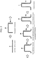
- Fig. 2 is an explanatory diagram illustrating a formed material manufacturing method, according to which the formed material 1 of Fig. 1 is manufactured.
- the formed material 1 is formed by performing multi-stage drawing and finish-ironing of a plate-like material metal sheet 2.
- Multi-stage drawing encompasses herein preliminary drawing and compression drawing performed at least once after the preliminary drawing.
- compression is performed three times (first to third compression operations).
- Metal sheets of various types of plated steel sheet can be used as the material metal sheet 2.
- Preliminary drawing is a step of forming a preform 20 having a trunk element 20a, through working of the material metal sheet 2.
- the trunk element 20a is a cylindrical body of larger diameter and smaller depth than those of the trunk portion 10 of Fig. 1 .
- the depth direction of the trunk element 20a is defined by the extension direction of the peripheral wall of the trunk element 20a.
- the entirety of the preform 20 makes up the trunk element 20a.
- a body having a flange portion may be formed as the preform 20. In this case the flange portion does not make up the trunk element 20a.
- the first compression drawing to third compression drawing are steps of forming the trunk portion 10 by drawing the trunk element 20a while applying to the trunk element 20a a compressive force 42a ( Fig. 5 ) along the depth direction of the trunk element 20a.
- Drawing of the trunk element 20a denotes herein reducing the diameter of the trunk element 20a and increasing the depth of the trunk element 20a.
- Fig. 3 is an explanatory diagram illustrating a forming die 3 used in preliminary drawing of Fig. 2 .
- Fig. 4 is an explanatory diagram illustrating preliminary drawing by the forming die 3 of Fig. 3 .
- the forming die 3 used in preliminary drawing includes a die 30, a punch 31 and a cushion pad 32.
- the die 30 is provided with a push-in hole 30a through which the material metal sheet 2 is pushed in together with the punch 31.
- the cushion pad 32 is disposed at an outer peripheral position of the punch 31 so as to oppose an end face of the die 30.
- the outer edge portion of the material metal sheet 2 is thrust to the point of coming off the restraint of the die 30 and the cushion pad 32, without the outer edge portion of the material metal sheet 2 being completely restrained by the die 30 and the cushion pad 32, as illustrated in Fig. 4 .
- the entirety of the material metal sheet 2 may be pushed in through the push-in hole 30a together with the punch 31.
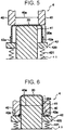
- Fig. 5 is an explanatory diagram illustrating a forming die 4 used in first compression drawing of Fig. 2 .
- Fig. 6 is an explanatory diagram illustrating the first compression drawing by the forming die 4 of Fig. 5 .
- the forming die 4 used in the first compression drawing includes a die 40, a punch 41 and a lifter pad 42.
- the die 40 is a member having a push-in hole 40a.
- the punch 41 is a cylindrical body that is inserted into the trunk element 20a and that pushes the trunk element 20a into the push-in hole 40a.
- the lifter pad 42 is disposed at the outer peripheral position of the punch 41 so as to oppose the die 40.
- the lifter pad 42 has a pad portion 420 and an urging portion 421.
- the pad portion 420 is an annular portion disposed at the outer peripheral position of the punch 41 so as to oppose the die 40.
- the urging portion 421 is disposed below the pad portion 420, and urges and supports the pad portion 420.
- the trunk element 20a is placed on the pad portion 420. The peripheral wall of the trunk element 20a becomes clamped by the die 40 and the pad portion 420 when the die 40 descends.
- the urging force (lifter pad force) of the urging portion 421 is applied to the trunk element 20a in the form of the compressive force 42a along the depth direction of the trunk element 20a. That is, the lifter pad 42 constitutes pressing means for applying, to the trunk element 20a, the compressive force 42a along the depth direction of the trunk element 20a.
- the die 40 descends, and as a result the trunk element 20a becomes inserted together with the punch 41 into the push-in hole 40a, and the trunk element 20a is drawn thereby.
- the compressive force 42a along the depth direction of the trunk element 20a continues to be applied to the trunk element 20a after the peripheral wall of the trunk element 20a has been clamped by the die 40 and the pad portion 420.
- the trunk element 20a is drawn while under application of a compressive force 42a.
- the trunk element 20a can be drawn without giving rise to wall thinning of the trunk element 20a, in a case where the compressive force 42a satisfies a predetermined condition.
- the thickness of the trunk element 20a having undergone the first compression operation becomes equal to or greater than the thickness of the trunk element 20a before the first compression drawing.
- the lower face of the lifter pad 42 during work is in a state of being capable of moving vertically while not abutting the top face of the punch holder 43. This is a state in which the die 40 having descended during work, without so-called bottoming, and the lifter pad 42 that would move upward on account of the urging force (lifter pad force) of the urging portion 421, are balanced via the trunk element 20a.
- a structure with bottoming of the lifter pad 42 entails that the urging force (lifter pad force) of the urging portion 421 is smaller than the deformation resistance force at the time of diameter reduction of the trunk element 20a by undergoing deformation.
- the molding forces between the lowered die 40 and the punch holder 43 via the lifter pad 42 are balanced, and accordingly the greater part of the urging force (lifter pad force) acting on the trunk element 20a is only deformation resistance during press-fit into the die 40, through reduction in the diameter of the trunk element 20a.
- factors contributing to wall thickening include mainly the forming die clearance between the die 40 and the punch, the die R, and the material strength (proof strength ⁇ cross-sectional area) of the trunk element 20a, which have a bearing on deformation resistance. Once established, these conditions are not easy to modify, and accordingly it is found that in a compression forming die of bottoming structure it is difficult to control increases and decreases in thickness in response to variations in the thickness of the material metal sheet.
- the second and third compression operations in Fig. 2 are carried out using a forming die having a configuration identical to that of the forming die 4 illustrated in Fig. 5 and Fig. 6 .
- the dimensions of the die 40 and of the punch 41 are modified as appropriate.
- the trunk element 20a after the first compression operation is drawn while under application of a compressive force 42a.
- the trunk element 20a after the second compression operation is drawn while the compressive force 42a is being applied thereto.
- the trunk element 20a becomes the trunk portion 10 as a result of the first to third compression operations, followed by finish-ironing.
- the thickness of the trunk element 20a in the third compression step being the pre-process of finish-ironing, takes on a predetermined thickness value. Finish-ironing is performed as a result with an appropriate forming die clearance such that no plating residue occurs, while satisfying inner-diameter roundness.
- the inventors studied the relationship between the size of the lifter pad force at the time of compression and the average thickness of the trunk portion peripheral wall (mm) of the trunk element 20a, by using, as the material metal sheet 2, a circular sheet obtained through Zn-Al-Mg plating of a cold-rolled sheet of ordinary steel, the circular sheet having a thickness of 1.60 to 1.95 mm, a plating deposition amount of 90 g/m 2 , and a diameter of 116 mm.
- Fig. 7 is a graph illustrating the relationship between lifter pad force and average thickness of the trunk portion peripheral wall in a first compression drawing step, using a Zn-Al-Mg plated steel sheet having a thickness of 1.8 mm, as the material metal sheet.
- the vertical axis represents the average thickness of the trunk portion peripheral wall after the first compression drawing
- the horizontal axis represents the lifter pad force (kN) in the first compression drawing.
- the average thickness of the trunk portion peripheral wall denotes a value resulting from averaging the thickness of the peripheral wall, from a radius curve end of the punch shoulder radius on the flange side up to a radius curve end of the die shoulder radius on the top wall side.
- the average thickness of the trunk portion peripheral wall increases substantially linearly as the lifter pad force of the first compression operation increases. It is likewise found that wall thickness becomes greater than the average thickness of the trunk portion peripheral wall at preliminary drawing, by setting the first compression operation lifter pad force to be about 15 kN or more.
- Fig. 8 is a graph illustrating the relationship between lifter pad force and average thickness of the trunk portion peripheral wall in a second compression drawing step.
- a Zn-Al-Mg plated steel sheet having a thickness of 1.8 mm was used as the material metal sheet, similarly to Fig. 7 .
- the vertical axis represents the average thickness of the trunk portion peripheral wall after second compression drawing
- the horizontal axis represents the lifter pad force (kN) in the second compression drawing.
- the average thickness of the trunk portion peripheral wall increases linearly accompanying an increase in the lifter pad force of the second compression drawing, similarly to the first compression drawing step.
- the thickness was increased to a thickness substantially identical to the forming die clearance with a lifter pad force of the second compression drawing of about 30 kN, and the thickness kept constant even the lifter pad force was increased beyond the above value.
- This reveals that, by adjusting (increasing) the lifter pad force, the thickness of the trunk element can be increased up to a thickness similar to the forming die clearance. It is found that setting the lifter pad force to about 10 kN or more in the second compression drawing results in a thicker wall than the average thickness of the trunk portion peripheral wall in the first compression drawing step.
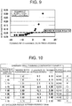
- Fig. 9 is a graph illustrating the relationship between forming die clearance in a finish-ironing step and inner-diameter roundness of the trunk portion peripheral wall after finish-ironing.
- Zn-Al-Mg plated steel sheets having a thickness of 1.60 to 1.95 mm were used as the material metal sheet.
- the vertical axis represents the inner-diameter roundness (mm) after finish-ironing and the horizontal axis represents finish-ironing forming die clearance.
- Fig. 10 sets out experimental results of a range of moldable material thickness in ordinary wall thinning (Comparative example 1).
- Fig. 11 sets out experimental results of a range of moldable material thickness in bottoming wall thickening (Comparative example 2), being a conventional wall thickening compression method.
- Fig. 12 sets out experimental results of a range of moldable material thickness in lifter controlled-wall thickening (example of the present invention).
- the figures illustrate thickness before finish-ironing, finish-ironing clearance, as well as inner-diameter roundness of the trunk portion peripheral wall after finish-ironing, and occurrence of plating residue after finish-ironing, versus the thickness of the material metal sheets used in the experiments, and illustrate also evaluation results based on the inner-diameter roundness and occurrence of plating residue. Whether or not lifter pad force is exerted at the time of the first compression drawing is notated for reference only in Fig. 12 , which depicts lifter controlled-wall thickening (example of the present invention).
- the clearance in the finish-ironing step was positive, and accordingly the inner-diameter roundness exceeded a specification 0.05 mm, without ironing.
- the clearance in the finish-ironing step was -10.9%, and thus the inner-diameter roundness after finish-ironing was satisfied, but plating residue was found to occur from sites of sliding against the die, in the finish-ironing step.
- the moldable material thickness in ordinary wall thinning lay in the range of 1.75 mm to 1.90 mm, having a width of 0.15 mm.
- the inner-diameter roundness exceeded a specification 0.05 mm only for a thickness of 1.60 mm of the material metal sheet. Plating residue was found to occur from sites of sliding against the die, in the finish-ironing step, in cases where the thickness of the material metal sheet was 1.85 mm or greater.
- the moldable material thickness in bottoming wall thickening was 1.65 mm to 1.80 mm, with a width of 0.15 mm. It is found that although the moldable material thickness shifts towards the thin side, as compared with the ordinary wall thinning in Comparative example 1, the width exhibits no change. This signifies that the molding margin in the case of variation of the thickness of the material metal sheet is identical for both ordinary wall thinning (Comparative example 1) and bottoming wall thickening (Comparative example 2).
- the compressive force applied to the trunk element can be controlled freely on the basis of the lifter pad force, in accordance with the thickness of the material metal sheet.
- the variation range of thickness before finish-ironing can be reduced by performing compression drawing by wall thickening through application of a lifter pad force during the first compression drawing, for a small thickness, of 1.60 mm to 1.75 mm, of the material metal sheet, and through wall thinning without application of a lifter pad force, for a large thickness, of 1.80 mm or greater, of the material metal sheet.
- the vertical axis represents the ironing rate Y and the horizontal axis represents a ratio X of the radius of curvature r of the die shoulder of a finish-ironing forming die and the average thickness tre of the peripheral wall of the trunk element before finish-ironing.
- a trunk portion is formed through drawing of a trunk element while a compressive force according to the thickness of a material metal sheet is applied to the trunk element along the depth direction of the trunk element. Accordingly, insufficient ironing and impairment of internal precision during finish-ironing can be avoided by increasing the lifter pad force, even when the thickness of the material metal sheet varies towards smaller values than in conventional instances. Further, the inner-diameter roundness can be satisfied while preventing occurrence of plating residue by decreasing the lifter pad force, even when, conversely, the thickness of the material metal sheet varies towards larger values than in conventional instances. In consequence, material metal sheets of wider thickness tolerance than conventional ones can be used as a result, which makes for easier material procurement.
- the present configuration is particularly useful in applications where a formed material such as a motor case is required to exhibit high-precision inner-diameter roundness.
- the lifter pad 42 which does not bottom out during work, constitutes pressing means, and hence it becomes possible to draw the trunk element 20a more reliably while applying to the trunk element 20a the compressive force 42a along the depth direction of the trunk element 20a.
- the lifter pad force in the compression drawing step can be adjusted in accordance with the thickness of the material metal sheet, and accordingly the average thickness of the peripheral wall of the trunk element before finish-ironing can be kept within a proper thickness range, regardless of the thickness of the material metal sheet, and stable ironing can be performed with a constant ironing clearance at all times.
- the formed material manufacturing method of the present invention satisfies 0 ⁇ Y ⁇ 11.7X-3.1, where Y denotes the ironing rate and X denotes the ratio of the radius of curvature r of the die shoulder of the finish-ironing forming die to the average thickness t re of the peripheral wall of the trunk element before finish-ironing; as a result, the inner-diameter roundness after finish-ironing can be satisfied, and the trunk element 20a can be drawn without giving rise to plating residue.
Landscapes
- Engineering & Computer Science (AREA)
- Mechanical Engineering (AREA)
- Shaping Metal By Deep-Drawing, Or The Like (AREA)
- Forging (AREA)
Abstract
Description
- The present invention relates to a formed material manufacturing method for manufacturing a formed material having a cylindrical trunk portion and a flange portion formed at an end section of the trunk portion.
- A formed material having a cylindrical trunk portion and a flange portion that is formed at an end section of the trunk portion is manufactured by drawing as described, for example, in
NPL 1 below. The trunk portion is formed through stretching of a material metal sheet by drawing. Accordingly, the thickness of the peripheral wall of the trunk portion is ordinarily smaller than the material thickness. - A formed material that is formed through drawing such as the above may be used in some instances as a motor case disclosed, for example, in
PTL 1. The peripheral wall of the trunk portion can be expected in this case to exhibit performance as a shield material for preventing magnetic leakage to the exterior of the motor case. The peripheral wall is also expected to deliver performance as a back yoke of a stator, depending on the structure of the motor. - The thicker the peripheral wall, the better is the performance as a shield material or as a back yoke. When manufacturing a formed material through drawing, as described above, the thickness of the material metal sheet is selected to be larger than a predetermined thickness of a trunk portion peripheral wall, in anticipation of decreases in thickness in the trunk portion, in such a manner that there is obtained the predetermined thickness of the trunk portion peripheral wall. However, the thickness of the material metal sheet is not constant at all times, and varies within an allowable range of thickness referred to as thickness tolerance. The decrement in thickness during drawing varies, for example, on account of changes in the state of a forming die and on account of variability in material characteristics.
- High-precision inner-diameter roundness may be required from the inner diameter of the motor case, in order to reduce motor vibration and noise. To that end, inner-diameter roundness is ordinarily enhanced through finish-ironing of the trunk portion, in a step that is performed once multi-stage drawing is over. Finish-ironing is accomplished by ironing the material of the trunk portion, sandwiched from the inside and the outside by two forming dies having a clearance therebetween that is set to be smaller than the material thickness of the trunk portion. Such setting of the clearance to be smaller than the material thickness of the trunk portion is referred to as negative clearance.
- When in this case the thickness of the material metal sheet is smaller than a planned thickness, or when a thickness reduction rate is large, on account of material characteristic variability in the material metal sheet or due to changes in the state of the forming die in a drawing step, the thickness of the trunk portion before ironing may become equal to or smaller than the planned thickness. The extent of ironing becomes then insufficient with the ironing forming die having been prepared beforehand, and inner-diameter roundness may decrease. When conversely the thickness of the material metal sheet is larger than the planned thickness or the thickness of the trunk portion before finish-ironing is excessively larger than the planned thickness due to, for example, changes in the state of the forming die during the drawing step or due to material characteristic variability, the inner-diameter roundness after finish-ironing is satisfied but other problems arise in that, for example, plating residue is generated that later on sloughs off the surface of the molded article, in cases where the surface of the material metal sheet is a surface-treated steel sheet having plating.
- These problems derive from the fact that the thickness of the trunk portion peripheral wall before finish-ironing varies due to variations in the thickness of the material metal sheet and variations in the thickness reduction rate during drawing, whereas the clearance of the forming die for performing finish-ironing is fixed; as a result, variations in the thickness of the trunk portion peripheral wall before finish-ironing cannot be absorbed by modifying the drawing conditions.
- Thus both a small and a large thickness of the trunk portion peripheral wall before finish-ironing are problematic in a case where a surface-treated steel sheet is used as the material metal sheet. Accordingly, a very strict tolerance is required from the thickness of the material metal sheet that is subjected to multi-stage drawing.
- Such being the case, forming dies have been proposed in which compression drawing is performed in a multi-stage drawing step, as a way of for preventing thinning of the trunk portion of a drawn member, as described, for example, in
PTL 2 below. - In this compression drawing forming die, a cylindrical member formed in a pre-process is fitted onto a deformation preventing member provided on a lower die, with an opening flange portion of the cylindrical member facing downward, and the opening flange portion is positioned in a recess of a plate provided on the lower die, whereby the outer periphery of the opening flange portion fits in the recess. The upper die is then lowered, to elicit press-fitting of a cylindrical portion of the cylindrical member into a die hole provided in the upper die, whereupon compression drawing is carried out through the action of the resulting compressive force.
- Since the deformation preventing member can move vertically with respect to a plate, reductions in thickness are thus suppressed, and rather increases in thickness (wall thickening) are made possible, with virtually no tensile force acting on the side wall of the cylindrical member.
- The compressive force acting on the trunk element in this case is equivalent to the deformation resistance of the trunk element at the time of press-fitting into the die hole. That is, factors contributing to increasing the thickness include mainly the forming die clearance between die and punch, a die shoulder radius and the material strength (proof strength × cross-sectional area) of the trunk element, all of which have a bearing on deformation resistance.
- [NPL 1] "Fundamentals of Plastic Forming", Masao MURAKAWA et al. (3), First Edition, Sangyo-Tosho Publishing Co. Ltd., January 16, 1990, pp. 104 to 107
-
- [PTL 1] Japanese Patent Application Publication No.
2013-51765 - [PTL 2] Japanese Utility Model Application Publication No.
H04-43415 - [PTL 3]
Japanese Patent No.5395301 - In the above compression drawing method, however, the cylindrical member is placed on a plate that is fixed to a lower die, and the cylindrical member is clamped between the plate and a die that descends from above. That is, thickness is increased through the action of a compressive force on the cylindrical member in a so-called bottomed-out state, and the thickness can therefore be increased. However, it remains difficult to control the increase or decrease in thickness by adjusting the compressive force in response to variations in the thickness of the material metal sheet.
- The present invention is contrived in order to solve the above problems, and the object thereof is to provide a formed material manufacturing method in which the inner-diameter roundness of a trunk portion can be maintained with high precision, by controlling increases and decreases in thickness to thereby adjust a peripheral wall thickness of the trunk element before finish-ironing, even when the thickness of the material metal sheet varies or forming die conditions vary.
- A further object of the present invention is to provide a formed material manufacturing method in which occurrence of plating film residue can be prevented by forming a clearance of a forming die used in finish-ironing, even in a case where a surface-treated steel sheet resulting from plating of the surface of a steel sheet is used as the material metal sheet.
- The formed material manufacturing method according to the present invention includes manufacturing a formed material having a cylindrical trunk portion and a flange portion formed at an end section of the trunk portion by performing multi-stage drawing of a material metal sheet,
wherein the multi-stage drawing includes: preliminary drawing that forms, from the material metal sheet, a preform having a trunk element; compression drawing that is performed at least once after the preliminary drawing, and that forms the trunk portion by drawing the trunk element while applying, to the trunk element, a compressive force along the depth direction of the trunk element, by using a forming die including a die having a push-in hole, a punch that is inserted into the trunk element and that pushes the trunk element into the push-in hole, and pressing means for applying the compressive force to a peripheral wall of the trunk element; and finish-ironing that is performed at least once after the compression drawing performed at least once,
the pressing means is a lifter pad having a pad portion which is disposed at an outer peripheral position of the punch so as to oppose the die and on which a lower end of the peripheral wall of the trunk element is placed, and a support portion configured to support the pad portion from below and to be capable of adjusting a support force with which the pad portion is supported,
the compression drawing performed at least once is performed so as to be complete by the time at which the pad portion reaches a bottom dead center, and the support force acts on the trunk element, as the compressive force, during compression drawing of the trunk element. - In the formed material manufacturing method of the present invention, a trunk portion is formed through drawing of a trunk element while a compressive force according to the thickness of a material metal sheet is applied to the trunk element along the depth direction of the trunk element. Accordingly, insufficient ironing and impairment of inner-diameter roundness during finish-ironing can be avoided by increasing the compressive force, even when the thickness of the material metal sheet varies more than expected towards smaller values. Further, the occurrence of plating residue can be prevented while satisfying the inner-diameter roundness, by decreasing the compressive force, even when, conversely, the thickness of the material metal sheet varies more than expected towards larger values. Accordingly, material metal sheets of wider thickness tolerance than conventional sheets can be used as a result, which makes for easier material procurement.
-
-
Fig. 1 is a perspective-view diagram illustrating a formedmaterial 1 manufactured in accordance with a formed material manufacturing method ofEmbodiment 1 of the present invention. -
Fig. 2 is an explanatory diagram illustrating a formed material manufacturing method, according to which the formed material ofFig. 1 is manufactured. -
Fig. 3 is an explanatory diagram illustrating a forming die used in preliminary drawing ofFig. 2 . -
Fig. 4 is an explanatory diagram illustrating preliminary drawing by the forming die ofFig. 3 . -
Fig. 5 is an explanatory diagram illustrating a forming die used in first compression drawing ofFig. 2 . -
Fig. 6 is an explanatory diagram illustrating the first compression drawing by the forming die ofFig. 5 . -
Fig. 7 is a graph illustrating the relationship between lifter pad force and average thickness of a trunk portion peripheral wall in a first compression drawing step. -
Fig. 8 is a graph illustrating the relationship between lifter pad force and average thickness of a trunk portion peripheral wall in a second compression drawing step. -
Fig. 9 is a graph illustrating the relationship between forming die clearance in finish-ironing and inner-diameter roundness of a trunk portion peripheral wall after finish-ironing. -
Fig. 10 is an explanatory diagram illustrating a range of moldable material thickness in ordinary wall thinning (Comparative example 1). -
Fig. 11 is an explanatory diagram illustrating a range of moldable material thickness in bottoming wall thickening (Comparative example 2). -
Fig. 12 is an explanatory diagram illustrating a range of moldable material thickness in lifter controlled-wall thickening (example of the present invention). -
Fig. 13 is a graph illustrating the relationship between ironing rate Y and X (=r/tre) in a Zn-Al-Mg-based alloy plated steel sheet. -
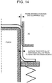
Fig. 14 is an explanatory diagram illustrating the relationship between the average thickness tre of the peripheral wall of a trunk element before finish-ironing and the clearance cre of a finish-ironing forming die, in finish-ironing. - An embodiment for carrying out the present invention will be explained next with reference to accompanying drawings.
-
Fig. 1 is a perspective-view diagram illustrating a formedmaterial 1 manufactured in accordance with a formed material manufacturing method ofEmbodiment 1 of the present invention. As illustrated inFig. 1 , the formedmaterial 1 manufactured in accordance with the formed material manufacturing method of the present invention has atrunk portion 10 and aflange portion 11. Thetrunk portion 10 is a cylindrical portion having atop wall 100 and aperipheral wall 101 extending from the outer edge of thetop wall 100. Thetop wall 100 may in some instances be referred to under other names, for example as bottom wall, depending on the orientation in which the formedmaterial 1 is used. InFig. 1 , thetrunk portion 10 is depicted as having a true circular cross-section, but thetrunk portion 10 may have some other cross-sectional shape, for example elliptical or square tubular. For example, thetop wall 100 can be further worked through formation of, for example, a protrusion that protrudes from thetop wall 100. Theflange portion 11 is a plate portion formed at the end section of the trunk portion 10 (end section of the peripheral wall 101). -
Fig. 2 is an explanatory diagram illustrating a formed material manufacturing method, according to which the formedmaterial 1 ofFig. 1 is manufactured. In the formed material manufacturing method of the present invention the formedmaterial 1 is formed by performing multi-stage drawing and finish-ironing of a plate-likematerial metal sheet 2. Multi-stage drawing encompasses herein preliminary drawing and compression drawing performed at least once after the preliminary drawing. In the formed material manufacturing method of the present embodiment, compression is performed three times (first to third compression operations). Metal sheets of various types of plated steel sheet can be used as thematerial metal sheet 2. - Preliminary drawing is a step of forming a
preform 20 having atrunk element 20a, through working of thematerial metal sheet 2. Thetrunk element 20a is a cylindrical body of larger diameter and smaller depth than those of thetrunk portion 10 ofFig. 1 . The depth direction of thetrunk element 20a is defined by the extension direction of the peripheral wall of thetrunk element 20a. In the present embodiment the entirety of thepreform 20 makes up thetrunk element 20a. However, a body having a flange portion may be formed as thepreform 20. In this case the flange portion does not make up thetrunk element 20a. - As explained in detail further on, the first compression drawing to third compression drawing are steps of forming the
trunk portion 10 by drawing thetrunk element 20a while applying to thetrunk element 20a acompressive force 42a (Fig. 5 ) along the depth direction of thetrunk element 20a. Drawing of thetrunk element 20a denotes herein reducing the diameter of thetrunk element 20a and increasing the depth of thetrunk element 20a. - Next,
Fig. 3 is an explanatory diagram illustrating a formingdie 3 used in preliminary drawing ofFig. 2 .Fig. 4 is an explanatory diagram illustrating preliminary drawing by the formingdie 3 ofFig. 3 . As illustrated inFig. 3 , the formingdie 3 used in preliminary drawing includes a die 30, apunch 31 and acushion pad 32. Thedie 30 is provided with a push-inhole 30a through which thematerial metal sheet 2 is pushed in together with thepunch 31. Thecushion pad 32 is disposed at an outer peripheral position of thepunch 31 so as to oppose an end face of thedie 30. Preliminarily, the outer edge portion of thematerial metal sheet 2 is thrust to the point of coming off the restraint of thedie 30 and thecushion pad 32, without the outer edge portion of thematerial metal sheet 2 being completely restrained by thedie 30 and thecushion pad 32, as illustrated inFig. 4 . The entirety of thematerial metal sheet 2 may be pushed in through the push-inhole 30a together with thepunch 31. In a case where apreform 20 having a flange portion is to be formed, as described above, it suffices to stop at a depth such that the outer edge portion of thematerial metal sheet 2 does not come off the restraint of thedie 30 and thecushion pad 32. - Next,
Fig. 5 is an explanatory diagram illustrating a formingdie 4 used in first compression drawing ofFig. 2 .Fig. 6 is an explanatory diagram illustrating the first compression drawing by the formingdie 4 ofFig. 5 . As illustrated inFig. 5 , the formingdie 4 used in the first compression drawing includes a die 40, apunch 41 and alifter pad 42. Thedie 40 is a member having a push-inhole 40a. Thepunch 41 is a cylindrical body that is inserted into thetrunk element 20a and that pushes thetrunk element 20a into the push-inhole 40a. - The
lifter pad 42 is disposed at the outer peripheral position of thepunch 41 so as to oppose thedie 40. Specifically, thelifter pad 42 has apad portion 420 and an urgingportion 421. Thepad portion 420 is an annular portion disposed at the outer peripheral position of thepunch 41 so as to oppose thedie 40. The urgingportion 421 is disposed below thepad portion 420, and urges and supports thepad portion 420. Thetrunk element 20a is placed on thepad portion 420. The peripheral wall of thetrunk element 20a becomes clamped by thedie 40 and thepad portion 420 when thedie 40 descends. As a result of clamping of the peripheral wall of thetrunk element 20a by thedie 40 and thepad portion 420, the urging force (lifter pad force) of the urgingportion 421 is applied to thetrunk element 20a in the form of thecompressive force 42a along the depth direction of thetrunk element 20a. That is, thelifter pad 42 constitutes pressing means for applying, to thetrunk element 20a, thecompressive force 42a along the depth direction of thetrunk element 20a. - As illustrated in
Fig. 6 , in the first compression drawing thedie 40 descends, and as a result thetrunk element 20a becomes inserted together with thepunch 41 into the push-inhole 40a, and thetrunk element 20a is drawn thereby. At this time, thecompressive force 42a along the depth direction of thetrunk element 20a continues to be applied to thetrunk element 20a after the peripheral wall of thetrunk element 20a has been clamped by thedie 40 and thepad portion 420. In the first compression operation, thus, thetrunk element 20a is drawn while under application of acompressive force 42a. As explained in detail further on, thetrunk element 20a can be drawn without giving rise to wall thinning of thetrunk element 20a, in a case where thecompressive force 42a satisfies a predetermined condition. As a result, the thickness of thetrunk element 20a having undergone the first compression operation becomes equal to or greater than the thickness of thetrunk element 20a before the first compression drawing. - The lower face of the
lifter pad 42 during work is in a state of being capable of moving vertically while not abutting the top face of the punch holder 43. This is a state in which thedie 40 having descended during work, without so-called bottoming, and thelifter pad 42 that would move upward on account of the urging force (lifter pad force) of the urgingportion 421, are balanced via thetrunk element 20a. - A structure with bottoming of the
lifter pad 42 entails that the urging force (lifter pad force) of the urgingportion 421 is smaller than the deformation resistance force at the time of diameter reduction of thetrunk element 20a by undergoing deformation. In this case, the molding forces between the lowered die 40 and the punch holder 43 via thelifter pad 42 are balanced, and accordingly the greater part of the urging force (lifter pad force) acting on thetrunk element 20a is only deformation resistance during press-fit into thedie 40, through reduction in the diameter of thetrunk element 20a. Therefore, factors contributing to wall thickening include mainly the forming die clearance between the die 40 and the punch, the die R, and the material strength (proof strength× cross-sectional area) of thetrunk element 20a, which have a bearing on deformation resistance. Once established, these conditions are not easy to modify, and accordingly it is found that in a compression forming die of bottoming structure it is difficult to control increases and decreases in thickness in response to variations in the thickness of the material metal sheet. - The second and third compression operations in
Fig. 2 are carried out using a forming die having a configuration identical to that of the formingdie 4 illustrated inFig. 5 and Fig. 6 . The dimensions of thedie 40 and of thepunch 41 are modified as appropriate. In the second compression operation, thus, thetrunk element 20a after the first compression operation is drawn while under application of acompressive force 42a. In the third compression operation, thetrunk element 20a after the second compression operation is drawn while thecompressive force 42a is being applied thereto. Thetrunk element 20a becomes thetrunk portion 10 as a result of the first to third compression operations, followed by finish-ironing. In the present invention it is important to adjust the compressive force in the first compression step to third compression step in such a manner that the thickness of thetrunk element 20a in the third compression step, being the pre-process of finish-ironing, takes on a predetermined thickness value. Finish-ironing is performed as a result with an appropriate forming die clearance such that no plating residue occurs, while satisfying inner-diameter roundness. - Examples are illustrated next. The inventors studied the relationship between the size of the lifter pad force at the time of compression and the average thickness of the trunk portion peripheral wall (mm) of the
trunk element 20a, by using, as thematerial metal sheet 2, a circular sheet obtained through Zn-Al-Mg plating of a cold-rolled sheet of ordinary steel, the circular sheet having a thickness of 1.60 to 1.95 mm, a plating deposition amount of 90 g/m2, and a diameter of 116 mm. The relationship between a finish-ironing forming die clearance and the inner-diameter roundness after finish-ironing was assessed usingtrunk elements 20a before finish-ironing, with various thicknesses of the peripheral wall of the trunk portion, and having been manufactured by modifying the lifter pad force during the compression step. There were also assessed a range of moldable material thickness for ordinary wall thinning in which no directional compressive force is applied (Comparative example 1), for bottoming wall thickening being conventional compression work (Comparative example 2), and for wall thickening controlled by lifter pad force of the present invention. There was further assessed a relationship between ironing rate and die shoulder radius (mm) in a finish-ironing step, over a moldable range within which inner-diameter roundness after finish-ironing is satisfied and no plating residue is observed to occur. The work conditions are as given below. The results are illustrated inFig. 7 . - Radius of curvature of die shoulder: 0.45 to 10 mm
- Punch diameter: preliminary drawing 66 mm, first compression drawing 54 mm, second compression drawing 43 mm, third drawing compression 36 mm, finish-ironing 36 mm
- Forming die clearance (single side) between die and punch: preliminary drawing 2.00 mm, first compression drawing 1.95 mm, second drawing compression 1.95 mm, third compression drawing 1.95 mm, finish-ironing 1.55 mm
- Lifter pad force: 0 to 100 kN
- Press oil: TN-20N
-
Fig. 7 is a graph illustrating the relationship between lifter pad force and average thickness of the trunk portion peripheral wall in a first compression drawing step, using a Zn-Al-Mg plated steel sheet having a thickness of 1.8 mm, as the material metal sheet. InFig. 7 , the vertical axis represents the average thickness of the trunk portion peripheral wall after the first compression drawing, and the horizontal axis represents the lifter pad force (kN) in the first compression drawing. The average thickness of the trunk portion peripheral wall denotes a value resulting from averaging the thickness of the peripheral wall, from a radius curve end of the punch shoulder radius on the flange side up to a radius curve end of the die shoulder radius on the top wall side. It is found that the average thickness of the trunk portion peripheral wall increases substantially linearly as the lifter pad force of the first compression operation increases. It is likewise found that wall thickness becomes greater than the average thickness of the trunk portion peripheral wall at preliminary drawing, by setting the first compression operation lifter pad force to be about 15 kN or more. -
Fig. 8 is a graph illustrating the relationship between lifter pad force and average thickness of the trunk portion peripheral wall in a second compression drawing step. Herein a Zn-Al-Mg plated steel sheet having a thickness of 1.8 mm was used as the material metal sheet, similarly toFig. 7 . InFig. 8 , the vertical axis represents the average thickness of the trunk portion peripheral wall after second compression drawing, and the horizontal axis represents the lifter pad force (kN) in the second compression drawing. Herein it is found that the average thickness of the trunk portion peripheral wall increases linearly accompanying an increase in the lifter pad force of the second compression drawing, similarly to the first compression drawing step. For a trunk element having been formed with a lifter pad force of 50 kN in the first compression drawing, the thickness was increased to a thickness substantially identical to the forming die clearance with a lifter pad force of the second compression drawing of about 30 kN, and the thickness kept constant even the lifter pad force was increased beyond the above value. This reveals that, by adjusting (increasing) the lifter pad force, the thickness of the trunk element can be increased up to a thickness similar to the forming die clearance. It is found that setting the lifter pad force to about 10 kN or more in the second compression drawing results in a thicker wall than the average thickness of the trunk portion peripheral wall in the first compression drawing step. -
Fig. 9 is a graph illustrating the relationship between forming die clearance in a finish-ironing step and inner-diameter roundness of the trunk portion peripheral wall after finish-ironing. Herein Zn-Al-Mg plated steel sheets having a thickness of 1.60 to 1.95 mm were used as the material metal sheet. InFig. 9 the vertical axis represents the inner-diameter roundness (mm) after finish-ironing and the horizontal axis represents finish-ironing forming die clearance. The finish-ironing forming die clearance is as follows.
- cre: finish-ironing forming die clearance
- tre: average thickness of the peripheral wall of the trunk element before finish-ironing
- It is found that the inner-diameter roundness increases sharply as the finish-ironing forming die clearance becomes larger. It was further found that an inner-diameter roundness specification of 0.05 mm or less can be satisfied at a region where the finish-ironing forming die clearance is negative i.e. by performing ironing of reducing the thickness of the trunk element.
-
Fig. 10 sets out experimental results of a range of moldable material thickness in ordinary wall thinning (Comparative example 1).Fig. 11 sets out experimental results of a range of moldable material thickness in bottoming wall thickening (Comparative example 2), being a conventional wall thickening compression method.Fig. 12 sets out experimental results of a range of moldable material thickness in lifter controlled-wall thickening (example of the present invention). The figures illustrate thickness before finish-ironing, finish-ironing clearance, as well as inner-diameter roundness of the trunk portion peripheral wall after finish-ironing, and occurrence of plating residue after finish-ironing, versus the thickness of the material metal sheets used in the experiments, and illustrate also evaluation results based on the inner-diameter roundness and occurrence of plating residue. Whether or not lifter pad force is exerted at the time of the first compression drawing is notated for reference only inFig. 12 , which depicts lifter controlled-wall thickening (example of the present invention). - No compressive force was applied to the trunk element in ordinary wall thinning of Comparative example 1 illustrated in
Fig. 10 , and accordingly thickness before finish-ironing decreased uniformly with respect to the thickness of the material metal sheet. - For a thickness of 1.60 to 1.75 mm of the material metal sheet, the clearance in the finish-ironing step was positive, and accordingly the inner-diameter roundness exceeded a specification 0.05 mm, without ironing. For a thickness of 1.95 mm of the material metal sheet, the clearance in the finish-ironing step was -10.9%, and thus the inner-diameter roundness after finish-ironing was satisfied, but plating residue was found to occur from sites of sliding against the die, in the finish-ironing step. As a result, the moldable material thickness in ordinary wall thinning (Comparative example 1) lay in the range of 1.75 mm to 1.90 mm, having a width of 0.15 mm.
- In bottoming wall thickening of Comparative example 2 illustrated in
Fig. 11 , a compressive force was applied to the trunk element, and accordingly although the thickness before finish-ironing decreased uniformly with respect to the thickness of the material metal sheet, the extent of the decrement was smaller than in Comparative example 1 (ordinary wall thinning). - The inner-diameter roundness exceeded a specification 0.05 mm only for a thickness of 1.60 mm of the material metal sheet. Plating residue was found to occur from sites of sliding against the die, in the finish-ironing step, in cases where the thickness of the material metal sheet was 1.85 mm or greater.
- In the above results, the moldable material thickness in bottoming wall thickening (Comparative example 2) was 1.65 mm to 1.80 mm, with a width of 0.15 mm. It is found that although the moldable material thickness shifts towards the thin side, as compared with the ordinary wall thinning in Comparative example 1, the width exhibits no change. This signifies that the molding margin in the case of variation of the thickness of the material metal sheet is identical for both ordinary wall thinning (Comparative example 1) and bottoming wall thickening (Comparative example 2).
- In wall thickening controlled by lifter pad force of the example of the present invention illustrated in
Fig. 12 , the compressive force applied to the trunk element can be controlled freely on the basis of the lifter pad force, in accordance with the thickness of the material metal sheet. In consequence, it becomes possible to reduce the variation range in thickness during a finish-ironing pre-process. For example as illustrated inFig. 12 , the variation range of thickness before finish-ironing can be reduced by performing compression drawing by wall thickening through application of a lifter pad force during the first compression drawing, for a small thickness, of 1.60 mm to 1.75 mm, of the material metal sheet, and through wall thinning without application of a lifter pad force, for a large thickness, of 1.80 mm or greater, of the material metal sheet. The condition of no lifter pad force being exerted corresponds to ordinary wall thinning in Comparative example 1. Plating residue was found to occur from sites of sliding against the die, in the finish-ironing step, in cases where the thickness of the material metal sheet was 1.95 mm, but roundness after finish-ironing satisfied a specification of 0.05 mm or less regardless of the thickness of the material metal sheet. In these results, the moldable material thickness in wall thickening controlled by lifter pad force (the present invention) lay thus in the range of 1.60 mm to 1.90 mm, with a range width of 0.30 mm. This indicates that in wall thickening controlled by lifter pad force of the example of the present invention the molding margin in case of variations in the thickness of the material metal sheet is wider than in ordinary wall thinning (Comparative example 1) and in bottoming wall thickening (Comparative example 2). That is, the range of the thickness of the material metal sheet over which molding is possible is wider in the formed material manufacturing method of the present invention than in ordinary wall thinning of Comparative example 1 and than in bottoming wall-thickening, being a conventional wall thickening compression method, of Comparative example 2. -
Fig. 13 is a graph illustrating the relationship between ironing rate Y and X (=r/tre) in a case where a Zn-Al-Mg-based alloy plated steel sheet is used as a material metal sheet. InFig. 13 the vertical axis represents the ironing rate Y and the horizontal axis represents a ratio X of the radius of curvature r of the die shoulder of a finish-ironing forming die and the average thickness tre of the peripheral wall of the trunk element before finish-ironing. - The ironing rate Y is defined as follows.

- cre: finish-ironing forming die clearance
- tre: average thickness of the peripheral wall of the trunk element before finish-ironing
- In the figure, the white circles (○) denote an evaluation rating to the effect that occurrence of plating residue can be suppressed, while the crosses (×) denote a rating to the effect that occurrence of plating residue cannot be suppressed. Further, the black circles (●) indicate that inner-diameter roundness exceeds 0.05 mm. As illustrated in
Fig. 13 , it was found that in the case of a Zn-Al-Mg-based alloy plated steel sheet it was possible to suppress occurrence of plating residue in a region below the straight line represented by Y = 11.7X-3.1. That is, it was found that occurrence of plating residue can be suppressed by establishing the average thickness tre of the peripheral wall of the trunk element before finish-ironing so as to satisfy 0 < Y ≤ 11.7X-3.1, as a result of wall thickening controlled by lifter pad force. Theterm 0 < Y prescribed in the above conditional expression derives from the fact that no ironing is performed in a case where the ironing rate Y is not higher than 0%. - In this formed material manufacturing method, a trunk portion is formed through drawing of a trunk element while a compressive force according to the thickness of a material metal sheet is applied to the trunk element along the depth direction of the trunk element. Accordingly, insufficient ironing and impairment of internal precision during finish-ironing can be avoided by increasing the lifter pad force, even when the thickness of the material metal sheet varies towards smaller values than in conventional instances. Further, the inner-diameter roundness can be satisfied while preventing occurrence of plating residue by decreasing the lifter pad force, even when, conversely, the thickness of the material metal sheet varies towards larger values than in conventional instances. In consequence, material metal sheets of wider thickness tolerance than conventional ones can be used as a result, which makes for easier material procurement.
- The present configuration is particularly useful in applications where a formed material such as a motor case is required to exhibit high-precision inner-diameter roundness.
- The
lifter pad 42, which does not bottom out during work, constitutes pressing means, and hence it becomes possible to draw thetrunk element 20a more reliably while applying to thetrunk element 20a thecompressive force 42a along the depth direction of thetrunk element 20a. - The lifter pad force in the compression drawing step can be adjusted in accordance with the thickness of the material metal sheet, and accordingly the average thickness of the peripheral wall of the trunk element before finish-ironing can be kept within a proper thickness range, regardless of the thickness of the material metal sheet, and stable ironing can be performed with a constant ironing clearance at all times.
- Further, the formed material manufacturing method of the present invention satisfies 0 < Y ≤ 11.7X-3.1, where Y denotes the ironing rate and X denotes the ratio of the radius of curvature r of the die shoulder of the finish-ironing forming die to the average thickness tre of the peripheral wall of the trunk element before finish-ironing; as a result, the inner-diameter roundness after finish-ironing can be satisfied, and the
trunk element 20a can be drawn without giving rise to plating residue. - In the explanation of the embodiment compression is carried out three times, but the number of compression operations may be modified as appropriate depending on the size and the required dimensional precision of the formed
material 1.
Claims (4)
- A formed material manufacturing method, comprising manufacturing a formed material having a cylindrical trunk portion and a flange portion formed at an end section of the trunk portion by performing multi-stage drawing of a material metal sheet,
wherein the multi-stage drawing includes:preliminary drawing that forms, from the material metal sheet, a preform having a trunk element;compression drawing that is performed at least once after the preliminary and that forms the trunk portion by drawing the trunk element while applying, to the trunk element, a compressive force along the depth direction of the trunk element, by using a forming die including a die having a push-in hole, a punch that is inserted into the trunk element and that pushes the trunk element into the push-in hole, and pressing means for applying the compressive force to a peripheral wall of the trunk element; andfinish-ironing that is performed at least once after the compression drawing performed at least once,the pressing means is a lifter pad having a pad portion which is disposed at an outer peripheral position of the punch so as to oppose the die and on which a lower end of the peripheral wall of the trunk element is placed, and a support portion configured to support the pad portion from below and to be capable of adjusting a support force with which the pad portion is supported,the compression drawing performed at least once is performed so as to be complete by the time at which the pad portion reaches a bottom dead center, andthe support force acts on the trunk element, as the compressive force, during compression drawing of the trunk element. - The formed material manufacturing method according to claim 1,
wherein, in the compression drawing performed at least once, the average thickness of the peripheral wall of the trunk element before the finish-ironing is adjusted by adjusting the support force with which the pad portion is supported, in accordance with the thickness of the material metal sheet. - The formed material manufacturing method according to claim 1 or 2,
wherein, in the finish-ironing performed at least once, a clearance cre of a forming die used in the finish-ironing is established so as to satisfy the relationship given by Expression (1) below, where X denotes a ratio of a radius of curvature r of a die shoulder of the forming die used in the finish-ironing to an average thickness tre of the peripheral wall of the trunk element before the finish-ironing, and Y denotes an ironing rate represented by {(tre-cre)/tre}×100:
- The formed material manufacturing method according to claim 1, wherein the material metal sheet is a Zn-based plated steel sheet obtained by performing Zn-based plating on the surface of a steel sheet.
Applications Claiming Priority (2)
| Application Number | Priority Date | Filing Date | Title |
|---|---|---|---|
| JP2015070609A JP6242363B2 (en) | 2015-03-31 | 2015-03-31 | Molding material manufacturing method |
| PCT/JP2016/058136 WO2016158383A1 (en) | 2015-03-31 | 2016-03-15 | Manufacturing method of molding material |
Publications (3)
| Publication Number | Publication Date |
|---|---|
| EP3278898A1 true EP3278898A1 (en) | 2018-02-07 |
| EP3278898A4 EP3278898A4 (en) | 2018-08-08 |
| EP3278898B1 EP3278898B1 (en) | 2021-10-13 |
Family
ID=57006050
Family Applications (1)
| Application Number | Title | Priority Date | Filing Date |
|---|---|---|---|
| EP16772266.9A Active EP3278898B1 (en) | 2015-03-31 | 2016-03-15 | Manufacturing method of molding material |
Country Status (15)
| Country | Link |
|---|---|
| US (1) | US11072013B2 (en) |
| EP (1) | EP3278898B1 (en) |
| JP (1) | JP6242363B2 (en) |
| KR (1) | KR102320520B1 (en) |
| CN (1) | CN107427890B (en) |
| AU (1) | AU2016241822B2 (en) |
| BR (1) | BR112017020581B1 (en) |
| CA (1) | CA2979675A1 (en) |
| EA (1) | EA034335B1 (en) |
| MX (1) | MX2017012383A (en) |
| MY (1) | MY175785A (en) |
| PH (1) | PH12017501754A1 (en) |
| SG (1) | SG11201707437RA (en) |
| TW (1) | TWI666072B (en) |
| WO (1) | WO2016158383A1 (en) |
Cited By (1)
| Publication number | Priority date | Publication date | Assignee | Title |
|---|---|---|---|---|
| EP3409394A4 (en) * | 2016-03-03 | 2019-05-08 | Nisshin Steel Co., Ltd. | METHOD FOR MANUFACTURING MOLDED ELEMENT |
Families Citing this family (4)
| Publication number | Priority date | Publication date | Assignee | Title |
|---|---|---|---|---|
| CN107186035B (en) * | 2017-06-29 | 2018-10-26 | 张家港幸运金属工艺品有限公司 | Ice bucket stretch forming process |
| CN109821985B (en) * | 2019-04-11 | 2020-04-28 | 成都纵远机械设备有限公司 | Manufacturing method of high-radioactivity waste glass solidified body storage tank |
| JP7417069B2 (en) * | 2020-02-04 | 2024-01-18 | 日本製鉄株式会社 | Molded material manufacturing method |
| JP7539241B2 (en) * | 2020-03-27 | 2024-08-23 | 大和製罐株式会社 | Battery case manufacturing method |
Family Cites Families (24)
| Publication number | Priority date | Publication date | Assignee | Title |
|---|---|---|---|---|
| JPS6032575U (en) | 1983-08-11 | 1985-03-05 | 東北三國工業株式会社 | Fuel pump |
| JPS60146526U (en) * | 1984-03-07 | 1985-09-28 | アイダエンジニアリング株式会社 | compression drawing mold |
| US5209099A (en) * | 1985-03-15 | 1993-05-11 | Weirton Steel Corporation | Draw-process methods, systems and tooling for fabricating one-piece can bodies |
| JPH07106394B2 (en) * | 1989-05-17 | 1995-11-15 | 東洋製罐株式会社 | Squeeze ironing can manufacturing method |
| JPH0443415A (en) | 1990-06-08 | 1992-02-13 | Ricoh Co Ltd | central processing unit |
| EP0664169B1 (en) * | 1993-12-22 | 1999-03-10 | TOYO KOHAN Co., Ltd | method of forming a metal can |
| JP3364124B2 (en) * | 1997-08-27 | 2003-01-08 | 本田技研工業株式会社 | Manufacturing method of bossed drum |
| JP3425068B2 (en) * | 1997-09-24 | 2003-07-07 | アイダエンジニアリング株式会社 | Method and apparatus for forming stepped cup-shaped member with flange |
| JP3415033B2 (en) * | 1998-06-24 | 2003-06-09 | アスモ株式会社 | Mold for thickening drawing and method of manufacturing yoke |
| JP3634999B2 (en) | 2000-03-16 | 2005-03-30 | 小島プレス工業株式会社 | Metal product molding method and molding die used therefor |
| JP2003005827A (en) * | 2001-06-26 | 2003-01-08 | Maspro Denkoh Corp | Remote monitoring system |
| JP4628047B2 (en) * | 2004-09-02 | 2011-02-09 | 東洋製罐株式会社 | Method of squeezing and ironing resin-coated metal plate, and resin-coated squeezing and ironing can using the same |
| JP5102042B2 (en) * | 2005-11-04 | 2012-12-19 | 東洋製罐株式会社 | Method of drawing and ironing resin-coated metal plate, and resin-coated drawing and ironing can using the same |
| JP4483933B2 (en) * | 2007-11-21 | 2010-06-16 | トヨタ自動車株式会社 | Press molding method and press molding apparatus |
| DE102009059197A1 (en) * | 2009-12-17 | 2011-06-22 | ThyssenKrupp Steel Europe AG, 47166 | Method and device for producing a half-shell part |
| EP2711104B1 (en) * | 2011-05-20 | 2023-01-11 | Nippon Steel Corporation | Press forming method |
| JP2013051765A (en) | 2011-08-30 | 2013-03-14 | Minebea Motor Manufacturing Corp | Dc motor |
| JP2013146751A (en) * | 2012-01-18 | 2013-08-01 | Kyoto Institute Of Technology | Working method and working device for workpiece |
| CA2882244C (en) | 2012-09-12 | 2017-06-06 | Nippon Steel & Sumitomo Metal Corporation | Method for producing curved part, and skeleton structure member of body shell of automobile |
| WO2014185428A1 (en) | 2013-05-13 | 2014-11-20 | 新日鐵住金株式会社 | Blank, molded plate, method of manufacturing press-molded product and press-molded product |
| TR201807893T4 (en) | 2013-06-28 | 2018-06-21 | Nisshin Steel Co Ltd | Ironing mold tooling and method for manufacturing molded material. |
| JP5613341B1 (en) * | 2014-01-27 | 2014-10-22 | 日新製鋼株式会社 | Ironing die and molding material manufacturing method |
| SG11201507205UA (en) * | 2014-03-20 | 2015-10-29 | Nisshin Steel Co Ltd | Formed material manufacturing method and formed material |
| JP5697787B1 (en) * | 2014-05-19 | 2015-04-08 | 日新製鋼株式会社 | Molding material manufacturing method |
-
2015
- 2015-03-31 JP JP2015070609A patent/JP6242363B2/en active Active
-
2016
- 2016-03-15 SG SG11201707437RA patent/SG11201707437RA/en unknown
- 2016-03-15 WO PCT/JP2016/058136 patent/WO2016158383A1/en not_active Ceased
- 2016-03-15 MX MX2017012383A patent/MX2017012383A/en unknown
- 2016-03-15 BR BR112017020581-5A patent/BR112017020581B1/en active IP Right Grant
- 2016-03-15 AU AU2016241822A patent/AU2016241822B2/en not_active Ceased
- 2016-03-15 MY MYPI2017703288A patent/MY175785A/en unknown
- 2016-03-15 EA EA201791793A patent/EA034335B1/en not_active IP Right Cessation
- 2016-03-15 KR KR1020177030952A patent/KR102320520B1/en active Active
- 2016-03-15 EP EP16772266.9A patent/EP3278898B1/en active Active
- 2016-03-15 CA CA2979675A patent/CA2979675A1/en not_active Abandoned
- 2016-03-15 US US15/562,051 patent/US11072013B2/en active Active
- 2016-03-15 CN CN201680021215.9A patent/CN107427890B/en active Active
- 2016-03-30 TW TW105110027A patent/TWI666072B/en active
-
2017
- 2017-09-25 PH PH12017501754A patent/PH12017501754A1/en unknown
Cited By (2)
| Publication number | Priority date | Publication date | Assignee | Title |
|---|---|---|---|---|
| EP3409394A4 (en) * | 2016-03-03 | 2019-05-08 | Nisshin Steel Co., Ltd. | METHOD FOR MANUFACTURING MOLDED ELEMENT |
| US10456820B2 (en) | 2016-03-03 | 2019-10-29 | Nippon Steel Nisshin Co., Ltd. | Method for manufacturing molded member |
Also Published As
| Publication number | Publication date |
|---|---|
| PH12017501754B1 (en) | 2018-04-02 |
| TWI666072B (en) | 2019-07-21 |
| TW201641178A (en) | 2016-12-01 |
| CN107427890A (en) | 2017-12-01 |
| KR20170132812A (en) | 2017-12-04 |
| KR102320520B1 (en) | 2021-11-02 |
| WO2016158383A1 (en) | 2016-10-06 |
| EA201791793A1 (en) | 2018-04-30 |
| MY175785A (en) | 2020-07-08 |
| CA2979675A1 (en) | 2016-10-06 |
| BR112017020581A2 (en) | 2018-07-03 |
| BR112017020581B1 (en) | 2021-06-29 |
| CN107427890B (en) | 2018-12-11 |
| EP3278898A4 (en) | 2018-08-08 |
| JP6242363B2 (en) | 2017-12-06 |
| US20180099325A1 (en) | 2018-04-12 |
| PH12017501754A1 (en) | 2018-04-02 |
| US11072013B2 (en) | 2021-07-27 |
| SG11201707437RA (en) | 2017-10-30 |
| EP3278898B1 (en) | 2021-10-13 |
| JP2016190245A (en) | 2016-11-10 |
| EA034335B1 (en) | 2020-01-29 |
| AU2016241822A1 (en) | 2017-09-28 |
| MX2017012383A (en) | 2017-12-14 |
| AU2016241822B2 (en) | 2020-01-02 |
Similar Documents
| Publication | Publication Date | Title |
|---|---|---|
| US10456820B2 (en) | Method for manufacturing molded member | |
| EP3278898B1 (en) | Manufacturing method of molding material | |
| EP2974808B1 (en) | Method for manufacturing molded material | |
| US11224909B2 (en) | Protrusion molding device, protrusion molding method, and molded article | |
| EP3401034B1 (en) | Molded material production method and molded material | |
| AU2016291507A1 (en) | Protrusion molding device, protrusion molding method, and molded article | |
| EP3520919B1 (en) | Method of manufacturing molded material, and said molded material |
Legal Events
| Date | Code | Title | Description |
|---|---|---|---|
| STAA | Information on the status of an ep patent application or granted ep patent |
Free format text: STATUS: THE INTERNATIONAL PUBLICATION HAS BEEN MADE |
|
| PUAI | Public reference made under article 153(3) epc to a published international application that has entered the european phase |
Free format text: ORIGINAL CODE: 0009012 |
|
| STAA | Information on the status of an ep patent application or granted ep patent |
Free format text: STATUS: REQUEST FOR EXAMINATION WAS MADE |
|
| 17P | Request for examination filed |
Effective date: 20170907 |
|
| AK | Designated contracting states |
Kind code of ref document: A1 Designated state(s): AL AT BE BG CH CY CZ DE DK EE ES FI FR GB GR HR HU IE IS IT LI LT LU LV MC MK MT NL NO PL PT RO RS SE SI SK SM TR |
|
| AX | Request for extension of the european patent |
Extension state: BA ME |
|
| DAV | Request for validation of the european patent (deleted) | ||
| DAX | Request for extension of the european patent (deleted) | ||
| A4 | Supplementary search report drawn up and despatched |
Effective date: 20180709 |
|
| RIC1 | Information provided on ipc code assigned before grant |
Ipc: B21D 22/28 20060101AFI20180703BHEP |
|
| RAP1 | Party data changed (applicant data changed or rights of an application transferred) |
Owner name: NIPPON STEEL NISSHIN CO., LTD. |
|
| RAP1 | Party data changed (applicant data changed or rights of an application transferred) |
Owner name: NIPPON STEEL CORPORATION |
|
| GRAP | Despatch of communication of intention to grant a patent |
Free format text: ORIGINAL CODE: EPIDOSNIGR1 |
|
| STAA | Information on the status of an ep patent application or granted ep patent |
Free format text: STATUS: GRANT OF PATENT IS INTENDED |
|
| INTG | Intention to grant announced |
Effective date: 20210629 |
|
| GRAS | Grant fee paid |
Free format text: ORIGINAL CODE: EPIDOSNIGR3 |
|
| GRAA | (expected) grant |
Free format text: ORIGINAL CODE: 0009210 |
|
| STAA | Information on the status of an ep patent application or granted ep patent |
Free format text: STATUS: THE PATENT HAS BEEN GRANTED |
|
| AK | Designated contracting states |
Kind code of ref document: B1 Designated state(s): AL AT BE BG CH CY CZ DE DK EE ES FI FR GB GR HR HU IE IS IT LI LT LU LV MC MK MT NL NO PL PT RO RS SE SI SK SM TR |
|
| REG | Reference to a national code |
Ref country code: GB Ref legal event code: FG4D |
|
| REG | Reference to a national code |
Ref country code: CH Ref legal event code: EP |
|
| REG | Reference to a national code |
Ref country code: DE Ref legal event code: R096 Ref document number: 602016064910 Country of ref document: DE |
|
| REG | Reference to a national code |
Ref country code: IE Ref legal event code: FG4D |
|
| REG | Reference to a national code |
Ref country code: AT Ref legal event code: REF Ref document number: 1437794 Country of ref document: AT Kind code of ref document: T Effective date: 20211115 |
|
| REG | Reference to a national code |
Ref country code: LT Ref legal event code: MG9D |
|
| REG | Reference to a national code |
Ref country code: NL Ref legal event code: MP Effective date: 20211013 |
|
| REG | Reference to a national code |
Ref country code: AT Ref legal event code: MK05 Ref document number: 1437794 Country of ref document: AT Kind code of ref document: T Effective date: 20211013 |
|
| PG25 | Lapsed in a contracting state [announced via postgrant information from national office to epo] |
Ref country code: RS Free format text: LAPSE BECAUSE OF FAILURE TO SUBMIT A TRANSLATION OF THE DESCRIPTION OR TO PAY THE FEE WITHIN THE PRESCRIBED TIME-LIMIT Effective date: 20211013 Ref country code: LT Free format text: LAPSE BECAUSE OF FAILURE TO SUBMIT A TRANSLATION OF THE DESCRIPTION OR TO PAY THE FEE WITHIN THE PRESCRIBED TIME-LIMIT Effective date: 20211013 Ref country code: FI Free format text: LAPSE BECAUSE OF FAILURE TO SUBMIT A TRANSLATION OF THE DESCRIPTION OR TO PAY THE FEE WITHIN THE PRESCRIBED TIME-LIMIT Effective date: 20211013 Ref country code: BG Free format text: LAPSE BECAUSE OF FAILURE TO SUBMIT A TRANSLATION OF THE DESCRIPTION OR TO PAY THE FEE WITHIN THE PRESCRIBED TIME-LIMIT Effective date: 20220113 Ref country code: AT Free format text: LAPSE BECAUSE OF FAILURE TO SUBMIT A TRANSLATION OF THE DESCRIPTION OR TO PAY THE FEE WITHIN THE PRESCRIBED TIME-LIMIT Effective date: 20211013 |
|
| PG25 | Lapsed in a contracting state [announced via postgrant information from national office to epo] |
Ref country code: IS Free format text: LAPSE BECAUSE OF FAILURE TO SUBMIT A TRANSLATION OF THE DESCRIPTION OR TO PAY THE FEE WITHIN THE PRESCRIBED TIME-LIMIT Effective date: 20220213 Ref country code: SE Free format text: LAPSE BECAUSE OF FAILURE TO SUBMIT A TRANSLATION OF THE DESCRIPTION OR TO PAY THE FEE WITHIN THE PRESCRIBED TIME-LIMIT Effective date: 20211013 Ref country code: PT Free format text: LAPSE BECAUSE OF FAILURE TO SUBMIT A TRANSLATION OF THE DESCRIPTION OR TO PAY THE FEE WITHIN THE PRESCRIBED TIME-LIMIT Effective date: 20220214 Ref country code: PL Free format text: LAPSE BECAUSE OF FAILURE TO SUBMIT A TRANSLATION OF THE DESCRIPTION OR TO PAY THE FEE WITHIN THE PRESCRIBED TIME-LIMIT Effective date: 20211013 Ref country code: NO Free format text: LAPSE BECAUSE OF FAILURE TO SUBMIT A TRANSLATION OF THE DESCRIPTION OR TO PAY THE FEE WITHIN THE PRESCRIBED TIME-LIMIT Effective date: 20220113 Ref country code: NL Free format text: LAPSE BECAUSE OF FAILURE TO SUBMIT A TRANSLATION OF THE DESCRIPTION OR TO PAY THE FEE WITHIN THE PRESCRIBED TIME-LIMIT Effective date: 20211013 Ref country code: LV Free format text: LAPSE BECAUSE OF FAILURE TO SUBMIT A TRANSLATION OF THE DESCRIPTION OR TO PAY THE FEE WITHIN THE PRESCRIBED TIME-LIMIT Effective date: 20211013 Ref country code: HR Free format text: LAPSE BECAUSE OF FAILURE TO SUBMIT A TRANSLATION OF THE DESCRIPTION OR TO PAY THE FEE WITHIN THE PRESCRIBED TIME-LIMIT Effective date: 20211013 Ref country code: GR Free format text: LAPSE BECAUSE OF FAILURE TO SUBMIT A TRANSLATION OF THE DESCRIPTION OR TO PAY THE FEE WITHIN THE PRESCRIBED TIME-LIMIT Effective date: 20220114 Ref country code: ES Free format text: LAPSE BECAUSE OF FAILURE TO SUBMIT A TRANSLATION OF THE DESCRIPTION OR TO PAY THE FEE WITHIN THE PRESCRIBED TIME-LIMIT Effective date: 20211013 |
|
| REG | Reference to a national code |
Ref country code: DE Ref legal event code: R097 Ref document number: 602016064910 Country of ref document: DE |
|
| PG25 | Lapsed in a contracting state [announced via postgrant information from national office to epo] |
Ref country code: SM Free format text: LAPSE BECAUSE OF FAILURE TO SUBMIT A TRANSLATION OF THE DESCRIPTION OR TO PAY THE FEE WITHIN THE PRESCRIBED TIME-LIMIT Effective date: 20211013 Ref country code: SK Free format text: LAPSE BECAUSE OF FAILURE TO SUBMIT A TRANSLATION OF THE DESCRIPTION OR TO PAY THE FEE WITHIN THE PRESCRIBED TIME-LIMIT Effective date: 20211013 Ref country code: RO Free format text: LAPSE BECAUSE OF FAILURE TO SUBMIT A TRANSLATION OF THE DESCRIPTION OR TO PAY THE FEE WITHIN THE PRESCRIBED TIME-LIMIT Effective date: 20211013 Ref country code: EE Free format text: LAPSE BECAUSE OF FAILURE TO SUBMIT A TRANSLATION OF THE DESCRIPTION OR TO PAY THE FEE WITHIN THE PRESCRIBED TIME-LIMIT Effective date: 20211013 Ref country code: DK Free format text: LAPSE BECAUSE OF FAILURE TO SUBMIT A TRANSLATION OF THE DESCRIPTION OR TO PAY THE FEE WITHIN THE PRESCRIBED TIME-LIMIT Effective date: 20211013 Ref country code: CZ Free format text: LAPSE BECAUSE OF FAILURE TO SUBMIT A TRANSLATION OF THE DESCRIPTION OR TO PAY THE FEE WITHIN THE PRESCRIBED TIME-LIMIT Effective date: 20211013 |
|
| PLBE | No opposition filed within time limit |
Free format text: ORIGINAL CODE: 0009261 |
|
| STAA | Information on the status of an ep patent application or granted ep patent |
Free format text: STATUS: NO OPPOSITION FILED WITHIN TIME LIMIT |
|
| 26N | No opposition filed |
Effective date: 20220714 |
|
| PG25 | Lapsed in a contracting state [announced via postgrant information from national office to epo] |
Ref country code: MC Free format text: LAPSE BECAUSE OF FAILURE TO SUBMIT A TRANSLATION OF THE DESCRIPTION OR TO PAY THE FEE WITHIN THE PRESCRIBED TIME-LIMIT Effective date: 20211013 Ref country code: AL Free format text: LAPSE BECAUSE OF FAILURE TO SUBMIT A TRANSLATION OF THE DESCRIPTION OR TO PAY THE FEE WITHIN THE PRESCRIBED TIME-LIMIT Effective date: 20211013 |
|
| REG | Reference to a national code |
Ref country code: CH Ref legal event code: PL |
|
| GBPC | Gb: european patent ceased through non-payment of renewal fee |
Effective date: 20220315 |
|
| PG25 | Lapsed in a contracting state [announced via postgrant information from national office to epo] |
Ref country code: SI Free format text: LAPSE BECAUSE OF FAILURE TO SUBMIT A TRANSLATION OF THE DESCRIPTION OR TO PAY THE FEE WITHIN THE PRESCRIBED TIME-LIMIT Effective date: 20211013 |
|
| REG | Reference to a national code |
Ref country code: BE Ref legal event code: MM Effective date: 20220331 |
|
| PG25 | Lapsed in a contracting state [announced via postgrant information from national office to epo] |
Ref country code: LU Free format text: LAPSE BECAUSE OF NON-PAYMENT OF DUE FEES Effective date: 20220315 Ref country code: LI Free format text: LAPSE BECAUSE OF NON-PAYMENT OF DUE FEES Effective date: 20220331 Ref country code: IE Free format text: LAPSE BECAUSE OF NON-PAYMENT OF DUE FEES Effective date: 20220315 Ref country code: GB Free format text: LAPSE BECAUSE OF NON-PAYMENT OF DUE FEES Effective date: 20220315 Ref country code: FR Free format text: LAPSE BECAUSE OF NON-PAYMENT OF DUE FEES Effective date: 20220331 Ref country code: CH Free format text: LAPSE BECAUSE OF NON-PAYMENT OF DUE FEES Effective date: 20220331 |
|
| PG25 | Lapsed in a contracting state [announced via postgrant information from national office to epo] |
Ref country code: BE Free format text: LAPSE BECAUSE OF NON-PAYMENT OF DUE FEES Effective date: 20220331 |
|
| PG25 | Lapsed in a contracting state [announced via postgrant information from national office to epo] |
Ref country code: IT Free format text: LAPSE BECAUSE OF FAILURE TO SUBMIT A TRANSLATION OF THE DESCRIPTION OR TO PAY THE FEE WITHIN THE PRESCRIBED TIME-LIMIT Effective date: 20211013 |
|
| PG25 | Lapsed in a contracting state [announced via postgrant information from national office to epo] |
Ref country code: HU Free format text: LAPSE BECAUSE OF FAILURE TO SUBMIT A TRANSLATION OF THE DESCRIPTION OR TO PAY THE FEE WITHIN THE PRESCRIBED TIME-LIMIT; INVALID AB INITIO Effective date: 20160315 |
|
| PG25 | Lapsed in a contracting state [announced via postgrant information from national office to epo] |
Ref country code: MK Free format text: LAPSE BECAUSE OF FAILURE TO SUBMIT A TRANSLATION OF THE DESCRIPTION OR TO PAY THE FEE WITHIN THE PRESCRIBED TIME-LIMIT Effective date: 20211013 Ref country code: CY Free format text: LAPSE BECAUSE OF FAILURE TO SUBMIT A TRANSLATION OF THE DESCRIPTION OR TO PAY THE FEE WITHIN THE PRESCRIBED TIME-LIMIT Effective date: 20211013 |
|
| PG25 | Lapsed in a contracting state [announced via postgrant information from national office to epo] |
Ref country code: TR Free format text: LAPSE BECAUSE OF FAILURE TO SUBMIT A TRANSLATION OF THE DESCRIPTION OR TO PAY THE FEE WITHIN THE PRESCRIBED TIME-LIMIT Effective date: 20211013 |
|
| PG25 | Lapsed in a contracting state [announced via postgrant information from national office to epo] |
Ref country code: MT Free format text: LAPSE BECAUSE OF FAILURE TO SUBMIT A TRANSLATION OF THE DESCRIPTION OR TO PAY THE FEE WITHIN THE PRESCRIBED TIME-LIMIT Effective date: 20211013 |
|
| PGFP | Annual fee paid to national office [announced via postgrant information from national office to epo] |
Ref country code: DE Payment date: 20250128 Year of fee payment: 10 |