EP3278136B1 - Improvements relating to monopulse radar apparatus - Google Patents
Improvements relating to monopulse radar apparatus Download PDFInfo
- Publication number
- EP3278136B1 EP3278136B1 EP16715059.8A EP16715059A EP3278136B1 EP 3278136 B1 EP3278136 B1 EP 3278136B1 EP 16715059 A EP16715059 A EP 16715059A EP 3278136 B1 EP3278136 B1 EP 3278136B1
- Authority
- EP
- European Patent Office
- Prior art keywords
- signals
- processor
- difference
- receive channels
- functioning
- Prior art date
- Legal status (The legal status is an assumption and is not a legal conclusion. Google has not performed a legal analysis and makes no representation as to the accuracy of the status listed.)
- Active
Links
Images


Classifications
-
- G—PHYSICS
- G01—MEASURING; TESTING
- G01S—RADIO DIRECTION-FINDING; RADIO NAVIGATION; DETERMINING DISTANCE OR VELOCITY BY USE OF RADIO WAVES; LOCATING OR PRESENCE-DETECTING BY USE OF THE REFLECTION OR RERADIATION OF RADIO WAVES; ANALOGOUS ARRANGEMENTS USING OTHER WAVES
- G01S13/00—Systems using the reflection or reradiation of radio waves, e.g. radar systems; Analogous systems using reflection or reradiation of waves whose nature or wavelength is irrelevant or unspecified
- G01S13/02—Systems using reflection of radio waves, e.g. primary radar systems; Analogous systems
- G01S13/06—Systems determining position data of a target
- G01S13/42—Simultaneous measurement of distance and other co-ordinates
- G01S13/44—Monopulse radar, i.e. simultaneous lobing
- G01S13/4472—Monopulse radar, i.e. simultaneous lobing with means specially adapted to airborne monopulse systems
-
- G—PHYSICS
- G01—MEASURING; TESTING
- G01S—RADIO DIRECTION-FINDING; RADIO NAVIGATION; DETERMINING DISTANCE OR VELOCITY BY USE OF RADIO WAVES; LOCATING OR PRESENCE-DETECTING BY USE OF THE REFLECTION OR RERADIATION OF RADIO WAVES; ANALOGOUS ARRANGEMENTS USING OTHER WAVES
- G01S7/00—Details of systems according to groups G01S13/00, G01S15/00, G01S17/00
- G01S7/02—Details of systems according to groups G01S13/00, G01S15/00, G01S17/00 of systems according to group G01S13/00
- G01S7/28—Details of pulse systems
- G01S7/285—Receivers
-
- F—MECHANICAL ENGINEERING; LIGHTING; HEATING; WEAPONS; BLASTING
- F41—WEAPONS
- F41G—WEAPON SIGHTS; AIMING
- F41G7/00—Direction control systems for self-propelled missiles
- F41G7/20—Direction control systems for self-propelled missiles based on continuous observation of target position
- F41G7/22—Homing guidance systems
- F41G7/2246—Active homing systems, i.e. comprising both a transmitter and a receiver
-
- F—MECHANICAL ENGINEERING; LIGHTING; HEATING; WEAPONS; BLASTING
- F41—WEAPONS
- F41G—WEAPON SIGHTS; AIMING
- F41G7/00—Direction control systems for self-propelled missiles
- F41G7/20—Direction control systems for self-propelled missiles based on continuous observation of target position
- F41G7/22—Homing guidance systems
- F41G7/2273—Homing guidance systems characterised by the type of waves
- F41G7/2286—Homing guidance systems characterised by the type of waves using radio waves
-
- G—PHYSICS
- G01—MEASURING; TESTING
- G01S—RADIO DIRECTION-FINDING; RADIO NAVIGATION; DETERMINING DISTANCE OR VELOCITY BY USE OF RADIO WAVES; LOCATING OR PRESENCE-DETECTING BY USE OF THE REFLECTION OR RERADIATION OF RADIO WAVES; ANALOGOUS ARRANGEMENTS USING OTHER WAVES
- G01S13/00—Systems using the reflection or reradiation of radio waves, e.g. radar systems; Analogous systems using reflection or reradiation of waves whose nature or wavelength is irrelevant or unspecified
- G01S13/02—Systems using reflection of radio waves, e.g. primary radar systems; Analogous systems
- G01S13/06—Systems determining position data of a target
- G01S13/42—Simultaneous measurement of distance and other co-ordinates
- G01S13/44—Monopulse radar, i.e. simultaneous lobing
- G01S13/4463—Monopulse radar, i.e. simultaneous lobing using phased arrays
-
- G—PHYSICS
- G01—MEASURING; TESTING
- G01S—RADIO DIRECTION-FINDING; RADIO NAVIGATION; DETERMINING DISTANCE OR VELOCITY BY USE OF RADIO WAVES; LOCATING OR PRESENCE-DETECTING BY USE OF THE REFLECTION OR RERADIATION OF RADIO WAVES; ANALOGOUS ARRANGEMENTS USING OTHER WAVES
- G01S13/00—Systems using the reflection or reradiation of radio waves, e.g. radar systems; Analogous systems using reflection or reradiation of waves whose nature or wavelength is irrelevant or unspecified
- G01S13/88—Radar or analogous systems specially adapted for specific applications
-
- G—PHYSICS
- G01—MEASURING; TESTING
- G01S—RADIO DIRECTION-FINDING; RADIO NAVIGATION; DETERMINING DISTANCE OR VELOCITY BY USE OF RADIO WAVES; LOCATING OR PRESENCE-DETECTING BY USE OF THE REFLECTION OR RERADIATION OF RADIO WAVES; ANALOGOUS ARRANGEMENTS USING OTHER WAVES
- G01S7/00—Details of systems according to groups G01S13/00, G01S15/00, G01S17/00
- G01S7/02—Details of systems according to groups G01S13/00, G01S15/00, G01S17/00 of systems according to group G01S13/00
- G01S7/40—Means for monitoring or calibrating
- G01S7/4004—Means for monitoring or calibrating of parts of a radar system
- G01S7/4021—Means for monitoring or calibrating of parts of a radar system of receivers
-
- G—PHYSICS
- G01—MEASURING; TESTING
- G01S—RADIO DIRECTION-FINDING; RADIO NAVIGATION; DETERMINING DISTANCE OR VELOCITY BY USE OF RADIO WAVES; LOCATING OR PRESENCE-DETECTING BY USE OF THE REFLECTION OR RERADIATION OF RADIO WAVES; ANALOGOUS ARRANGEMENTS USING OTHER WAVES
- G01S13/00—Systems using the reflection or reradiation of radio waves, e.g. radar systems; Analogous systems using reflection or reradiation of waves whose nature or wavelength is irrelevant or unspecified
- G01S13/88—Radar or analogous systems specially adapted for specific applications
- G01S13/883—Radar or analogous systems specially adapted for specific applications for missile homing, autodirectors
Definitions
- This invention relates improvements to monopulse radar apparatus. It is anticipated that the invention will find particular application in the field of airborne monopulse radar apparatus.
- Monopulse radar systems are known, for example from US Patent Number 3,560974 to Lecourtier et al.
- multiple overlapping beams are emitted from an antenna in a manner such that target reflections arising from a single pulse enable the direction to the target to be deduced.
- such systems comprise an array of feed elements disposed around a boresight of the antenna, such that difference signals between the elements can be obtained in two coordinate planes, most normally the azimuth and elevation planes.
- These difference signals together with a sum signal obtained by adding the signals from each element, enable the angle of the target off-boresight, and its range, to be calculated in a known manner.
- Advantages of monopulse systems over single antenna systems include the provision of more accurate azimuth and elevation position estimation, and the ability to detect jamming signals. These advantages make the monopulse radar arrangement highly desirable for applications in tracking radar.
- Known monopulse radar systems typically comprise four feed elements disposed in a square symmetrical arrangement around the boresight of the antenna. Each feed element is connected to one input port of a comparator network.
- the comparator network is a collection of coaxial cables, stripline or waveguide together with appropriate dividers and combiners, arranged such that its output ports provide the sum, azimuth and elevation differences, and diagonal difference signals. The diagonal difference signal facilitates the detection of jamming signals.
- the comparator is thus a hardware device designed to manipulate the physical signals received by the feed elements to provide the sum and difference signals required for further processing to track objects using the radar.
- US 2012/169540 A1 discloses a method for compensating for the failure of an element in a phased array antenna assembly.
- US 6546238 B1 discloses a dynamic signal routing system for an antenna array.
- the processor is arranged to monitor the received signals over a predetermined number of pulses transmitted by a transmitter associated with the monopulse radar apparatus, and wherein the processor is configured such that a malfunction is detected when one of the received signals changes by an amount greater than a predetermined threshold level within the predetermined number of pulses.
- the predetermined threshold level can be selected depending on the application for which the apparatus is intended. In one embodiment the predetermined threshold level is 1 dB, but the predetermined threshold level may be selected to be in the range between 0.5 dB and 5 dB.
- the predetermined number of pulses can also be selected depending on the application for which the apparatus is intended. In one embodiment the predetermined number of pulses is 3, but the predetermined number of pulses may be selected to be in the range between 2 and 15.
- each of the plurality of receive channels comprises an antenna feed element, the feed elements being disposed symmetrically around the boresight of the antenna.
- the present invention provides four receive channels.
- the four feed elements associated with the receive channels may be disposed in a square configuration, with the antenna boresight passing through the centre of the square.
- the processor is configured such that, in the event that a malfunction is detected in one of the plurality of receive channels, the sum signal is calculated using the signals from the two feed elements associated with functioning receive channels and adjacent the malfunctioning feed element.
- the sum signal may be calculated as a scaled sum of the signals received at the two functioning feed elements associated with functioning receive channels and adjacent the malfunctioning feed element. The scaled sum signal can be calculated to be more consistent with the sum signal obtained prior to a malfunction.
- the computer processing means may be configured such that, in the event that a malfunction is detected in one of the plurality of receive channels, the difference signals are calculated using the signals from the two feed elements associated with the functioning receive channels and adjacent one another in the direction of the difference being taken. It has been found that these calculations provide a better representation of the difference signals than other possible methods of combining the signals from the remaining, functioning antenna elements.
- the difference signals may be calculated as scaled differences of the signals received at the two feed elements associated with the functioning receive channels and adjacent one another in the direction of the difference being taken. As with the sum signal, the scaled difference signals can be calculated to be more consistent with the difference signals obtained prior to a malfunction.
- the invention extends to a missile having a tracking radar, the tracking radar comprising a monopulse radar apparatus as described above.
- the enhanced robustness achieved by monopulse radars using the present invention is expected to find particular application in seeker devices used in missiles.
- FIG. 1 is a schematic illustration of a monopulse radar apparatus 100 in accordance with a first embodiment of the invention.
- Apparatus 100 comprises a feed element cluster 110, having four feed elements A, B, C, and D disposed in the focal plane of a parabolic reflector 120.
- the feed elements act both to transmit a radio frequency signal, which may have a power of order several megawatts, and to receive signals reflected from potential targets.
- a single transmitter 130 generates the waveform for transmission.
- the waveform is split into separate signals for transmission from each of the feed elements A, B , C, D. The split is performed such that, as far as practicable, each of the elements transmits the same waveform.
- Each of the signals for transmission is passed, via waveguide, to a circulator 140, and then, again through waveguide, to its respective feed element for ongoing transmission out of the system and towards a target for observation.
- Returned signals comprising reflections of the transmitted signals from the target or other objects, are focussed onto the feed element cluster 110 by the reflector 120.
- Each feed element outputs a signal through waveguide to that feed elements associated circulator 140.
- the circulator is arranged such that, whilst signals from the transmitter are passed to the feed elements, received signals, entering a different input of the circulator, are passed to a respective feed element receiver 150.
- Each feed element receiver 150 includes an analogue-to-digital converter, such that a digital output is provided to processor 160.
- Processor 160 measures the magnitude and phase of the received signal, and combines each of the four received signals as described below.
- the apparatus 100 comprises four receive channels, each having a feed element ( A, B, C, or D) for the reception of RF signals, and an analogue to digital converter 150 communicating with the feed element via co-axial cable. The output of each receive channel is passed directly to the processor 160.
- the processor 160 is programmed to perform the function of a hardware comparator, so as to produce a sum signal ( ⁇ ), azimuth and elevation difference signals ( ⁇ AZ and ⁇ EL respectively) and a diagonal difference Q .
- a hardware comparator In reality, hardware comparators suffer from losses, which are eliminated through the direct connection of the feed elements to a receiver.
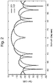
- Figure 2 illustrates example simulated patterns, in azimuth cut, for ⁇ AZ and ⁇ AZ .
- the sum pattern is shown in full line, reference 201 and the difference pattern is shown in dashed line, reference 202.
- the malfunction may be a partial or complete failure of the receive channel.
- a malfunction may be caused, for example, by a blockage in the feed element, by damage to the feed element, or by damage to another part of the receive channel, such as the connecting co-axial cable.
- a malfunction may be detected by monitoring the signals from the receive channels, either individually or in combination. For example, a sudden drop in the signal received from one feed element may be indicative of a malfunction in that feed element. Similarly, sudden changes in the balance between the different channels may also be indicative of malfunction in one of the feed elements. Such sudden changes can be readily detected by the processor 160, for example by setting threshold change level such that, should the signal from one feed element change by more than a threshold level within a predetermined number of consecutive transmit pulses, or should one of the difference signals change by more than a threshold level within a predetermined number of consecutive transmit pulses, further signal processing is accomplished using the scaled sum and difference signals described below, rather than the processing based on signals from all four of the feed elements in the feed element cluster.
- Simulations can be performed to identify the dependence of the difference signals on a relative loss in the signal from one of the elements in order to assist in determining the threshold level for a particular application.
- the predetermined number of consecutive transmit pulses can be determined in light of the particular application for which the apparatus is intended. Where it is desired to minimise the number of false malfunction detections, a larger number of pulses will be selected; whilst, where it is more important to ensure continuous functioning of the apparatus, a smaller number of pulses may be selected. For example, the predetermined number may be between 2 and 15 consecutive pulses.
- the threshold level is selected to be an increase in the RMS difference signal of greater than 1 dB, and the predetermined number of pulses is selected to be 3 consecutive transmit pulses.
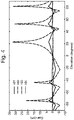
- Figure 3 illustrates these permutations for the azimuth cut through the ⁇ pattern
- Figure 4 illustrates these permutations for the elevation cut through the ⁇ pattern
- the BCD permutation is represented by line 301; the CD permutation by line 302; the BD permutation by line 303; and the BC permutation by line 304.
- Like reference numerals, but incremented by 100,, but incremented by 100, are used to refer to the same permutations in Figure 4 .
- Analogous relationships can be used for calculation of ⁇ EL s .
- the difference between the pattern obtained with all elements functioning, and those obtained using the above relationships for ⁇ AZ s is illustrated in Figure 5 .
- line 501 represents the BCD permutation
- line 502 represents the CD permutation
- line 503 represents the BC permutation.
- the difference between the pattern obtained with all elements functioning, and those obtained using the analogous relationships for ⁇ EL s are shown in Figure 6 .
- line 601 represents the BCD permutation
- line 602 represents the BD permutation
- line 603 represents the BC permutation.
- the different combinations of feed elements can squint the beam or cause a change in the gain.
- relationship (6) provides the best fit to the difference signal obtained when all four feed elements are functioning normally.
- Figure 6 shows the simulations for ⁇ EL s . Again it is clear that the different combinations can squint the beam or cause a change in gain, but that the best result is obtained using relationship (7).
- the RMS difference between the difference signal and the scaled difference signal obtained from relationship (6) or (7) is 0.24 dB. Whilst this fit is not as good as that for the sum signal, it is clear that it provides a useable approximation to the actual difference signals to enable continued operation of the antenna despite the presence of a failed element. It is currently thought that the relationships (6) and (7) provide the best fit because they allow the creation of the difference cuts without using the section of the monopulse horn that is damaged.
Landscapes
- Engineering & Computer Science (AREA)
- Radar, Positioning & Navigation (AREA)
- Remote Sensing (AREA)
- Physics & Mathematics (AREA)
- Computer Networks & Wireless Communication (AREA)
- General Physics & Mathematics (AREA)
- Chemical & Material Sciences (AREA)
- Combustion & Propulsion (AREA)
- General Engineering & Computer Science (AREA)
- Electromagnetism (AREA)
- Radar Systems Or Details Thereof (AREA)
- Measurement Of Levels Of Liquids Or Fluent Solid Materials (AREA)
Applications Claiming Priority (3)
| Application Number | Priority Date | Filing Date | Title |
|---|---|---|---|
| EP15275107.9A EP3076200A1 (en) | 2015-03-31 | 2015-03-31 | Improvements relating to monopulse radar apparatus |
| GB1505562.7A GB2536923B (en) | 2015-03-31 | 2015-03-31 | Monopulse radar apparatus with means of compensating for a failed receive channel |
| PCT/GB2016/050901 WO2016156847A1 (en) | 2015-03-31 | 2016-03-31 | Improvements relating to monopulse radar apparatus |
Publications (2)
| Publication Number | Publication Date |
|---|---|
| EP3278136A1 EP3278136A1 (en) | 2018-02-07 |
| EP3278136B1 true EP3278136B1 (en) | 2022-11-02 |
Family
ID=55697229
Family Applications (1)
| Application Number | Title | Priority Date | Filing Date |
|---|---|---|---|
| EP16715059.8A Active EP3278136B1 (en) | 2015-03-31 | 2016-03-31 | Improvements relating to monopulse radar apparatus |
Country Status (7)
| Country | Link |
|---|---|
| US (1) | US11105914B2 (pl) |
| EP (1) | EP3278136B1 (pl) |
| AU (2) | AU2016240300A1 (pl) |
| CA (1) | CA2981105C (pl) |
| ES (1) | ES2931340T3 (pl) |
| PL (1) | PL3278136T3 (pl) |
| WO (1) | WO2016156847A1 (pl) |
Families Citing this family (1)
| Publication number | Priority date | Publication date | Assignee | Title |
|---|---|---|---|---|
| CN111751793B (zh) * | 2020-07-02 | 2021-07-27 | 中国人民解放军海军航空大学 | 双平面脉冲多普勒雷达导引头通道合并与时分处理电路 |
Citations (2)
| Publication number | Priority date | Publication date | Assignee | Title |
|---|---|---|---|---|
| US3239836A (en) * | 1961-02-28 | 1966-03-08 | Sperry Rand Corp | Simplified monopulse radar receiver |
| US3277467A (en) * | 1964-12-16 | 1966-10-04 | Texas Instruments Inc | Time sharing radar-altimeter |
Family Cites Families (12)
| Publication number | Priority date | Publication date | Assignee | Title |
|---|---|---|---|---|
| FR1558535A (pl) | 1968-01-09 | 1969-02-28 | ||
| US6483478B2 (en) * | 2001-01-31 | 2002-11-19 | Lockheed Martin Corporation | Monopulse array radar with single difference beam for simultaneous azimuth and elevation angle determination |
| US6456238B1 (en) * | 2001-05-15 | 2002-09-24 | Raytheon Company | Dynamic signal routing in electronically scanned antenna systems |
| US6819285B1 (en) * | 2004-02-03 | 2004-11-16 | Lockheed Martin Corporation | Monopulse radar system for determining the height of a target |
| JP2006003097A (ja) | 2004-06-15 | 2006-01-05 | Fujitsu Ten Ltd | レーダ装置 |
| EP1788407B1 (en) | 2005-11-22 | 2015-05-27 | Fujitsu Ten Limited | Radar apparatus |
| US7702295B1 (en) * | 2006-12-22 | 2010-04-20 | Nortel Networks Limited | Frequency agile duplex filter |
| FR2940686B1 (fr) * | 2008-12-30 | 2011-03-18 | Thales Sa | Procede et systeme de localisation d'une cible dans un systeme interrogation reponse (iff). |
| EP2476163B1 (en) * | 2009-09-09 | 2018-07-25 | BAE Systems PLC | Antenna failure compensation |
| ES2428415T3 (es) * | 2010-11-27 | 2013-11-07 | Eads Deutschland Gmbh | Procedimiento para la determinación de la dirección por medio de la formación de monoimpulsos |
| US9121930B2 (en) * | 2012-06-25 | 2015-09-01 | Autoliv Asp, Inc. | Two-channel monopulse radar for three-dimensional detection |
| AU2013328486B2 (en) | 2012-10-08 | 2017-11-09 | Mbda Uk Limited | Improvements in and relating to radar receivers |
-
2016
- 2016-03-31 CA CA2981105A patent/CA2981105C/en active Active
- 2016-03-31 PL PL16715059.8T patent/PL3278136T3/pl unknown
- 2016-03-31 ES ES16715059T patent/ES2931340T3/es active Active
- 2016-03-31 US US15/562,091 patent/US11105914B2/en active Active
- 2016-03-31 WO PCT/GB2016/050901 patent/WO2016156847A1/en not_active Ceased
- 2016-03-31 AU AU2016240300A patent/AU2016240300A1/en not_active Abandoned
- 2016-03-31 EP EP16715059.8A patent/EP3278136B1/en active Active
-
2020
- 2020-06-01 AU AU2020203605A patent/AU2020203605B2/en active Active
Patent Citations (2)
| Publication number | Priority date | Publication date | Assignee | Title |
|---|---|---|---|---|
| US3239836A (en) * | 1961-02-28 | 1966-03-08 | Sperry Rand Corp | Simplified monopulse radar receiver |
| US3277467A (en) * | 1964-12-16 | 1966-10-04 | Texas Instruments Inc | Time sharing radar-altimeter |
Also Published As
| Publication number | Publication date |
|---|---|
| AU2016240300A1 (en) | 2017-10-19 |
| US20180074183A1 (en) | 2018-03-15 |
| WO2016156847A1 (en) | 2016-10-06 |
| US11105914B2 (en) | 2021-08-31 |
| ES2931340T3 (es) | 2022-12-28 |
| PL3278136T3 (pl) | 2023-01-23 |
| EP3278136A1 (en) | 2018-02-07 |
| CA2981105C (en) | 2023-08-29 |
| CA2981105A1 (en) | 2016-10-06 |
| AU2020203605A1 (en) | 2020-06-25 |
| AU2020203605B2 (en) | 2021-12-02 |
Similar Documents
| Publication | Publication Date | Title |
|---|---|---|
| EP3278137B1 (en) | Sequential multi-beam radar for maximum likelihood tracking and fence search | |
| US7626538B2 (en) | Augmented passive tracking of moving emitter | |
| CN105929370B (zh) | 栅瓣检测的基于数字波束形成的分辨 | |
| US11493620B2 (en) | Distributed monopulse radar antenna array for collision avoidance | |
| EP2919034A1 (en) | High precision radar to track aerial targets | |
| KR101929512B1 (ko) | 밀리미터파 공대지레이다의 각도 정보 융합 기법을 이용한 표적의 타격 각도 예측 장치 및 그 방법 | |
| KR102188034B1 (ko) | 위상 배열 레이다의 부엽 차단 시스템 | |
| US20240219552A1 (en) | Mimo radar using a frequency scanning antenna | |
| AU2020203605B2 (en) | Improvements relating to monopulse radar apparatus | |
| EP3076200A1 (en) | Improvements relating to monopulse radar apparatus | |
| EP0020104A1 (en) | Improvements in or relating to secondary surveillance radar | |
| EP0621654A2 (en) | An active antenna array | |
| EP2851647A1 (en) | Microwave system with enhanced capability to detect, identify and localize moving targets | |
| GB2536923A (en) | Improvements relating to monopulse radar apparatus | |
| RU2188436C1 (ru) | Бортовая радиолокационная станция для самолетной системы управления вооружением | |
| US3238530A (en) | Direction finding receiver systems | |
| Elgamel et al. | Target tracking enhancement using a Kalman filter in the presence of interference | |
| JP2005233673A (ja) | レーダ装置 | |
| Gilpin et al. | Real-Time Multiple Input Multiple Output (MIMO) Radar Using Software Defined Radio | |
| RU2548682C1 (ru) | Способ обнаружения и сопровождения траектории цели | |
| YiNan et al. | Angle estimation for two closely spaced targets with polarization monopulse radar | |
| Hussein et al. | Target tracking radar | |
| KR101958469B1 (ko) | 표적 조준 장치 및 그 방법 | |
| Kumar et al. | Online Calibration Philosophy for AESA Based Airborne Secondary Surveillance Radar | |
| Ashwini et al. | Design and Implementation of Dual Channel Monopulse Receiver |
Legal Events
| Date | Code | Title | Description |
|---|---|---|---|
| STAA | Information on the status of an ep patent application or granted ep patent |
Free format text: STATUS: THE INTERNATIONAL PUBLICATION HAS BEEN MADE |
|
| PUAI | Public reference made under article 153(3) epc to a published international application that has entered the european phase |
Free format text: ORIGINAL CODE: 0009012 |
|
| STAA | Information on the status of an ep patent application or granted ep patent |
Free format text: STATUS: REQUEST FOR EXAMINATION WAS MADE |
|
| 17P | Request for examination filed |
Effective date: 20171010 |
|
| AK | Designated contracting states |
Kind code of ref document: A1 Designated state(s): AL AT BE BG CH CY CZ DE DK EE ES FI FR GB GR HR HU IE IS IT LI LT LU LV MC MK MT NL NO PL PT RO RS SE SI SK SM TR |
|
| AX | Request for extension of the european patent |
Extension state: BA ME |
|
| DAV | Request for validation of the european patent (deleted) | ||
| DAX | Request for extension of the european patent (deleted) | ||
| STAA | Information on the status of an ep patent application or granted ep patent |
Free format text: STATUS: EXAMINATION IS IN PROGRESS |
|
| 17Q | First examination report despatched |
Effective date: 20200218 |
|
| GRAP | Despatch of communication of intention to grant a patent |
Free format text: ORIGINAL CODE: EPIDOSNIGR1 |
|
| STAA | Information on the status of an ep patent application or granted ep patent |
Free format text: STATUS: GRANT OF PATENT IS INTENDED |
|
| INTG | Intention to grant announced |
Effective date: 20220624 |
|
| GRAS | Grant fee paid |
Free format text: ORIGINAL CODE: EPIDOSNIGR3 |
|
| GRAA | (expected) grant |
Free format text: ORIGINAL CODE: 0009210 |
|
| STAA | Information on the status of an ep patent application or granted ep patent |
Free format text: STATUS: THE PATENT HAS BEEN GRANTED |
|
| AK | Designated contracting states |
Kind code of ref document: B1 Designated state(s): AL AT BE BG CH CY CZ DE DK EE ES FI FR GB GR HR HU IE IS IT LI LT LU LV MC MK MT NL NO PL PT RO RS SE SI SK SM TR |
|
| REG | Reference to a national code |
Ref country code: GB Ref legal event code: FG4D |
|
| REG | Reference to a national code |
Ref country code: CH Ref legal event code: EP Ref country code: AT Ref legal event code: REF Ref document number: 1529142 Country of ref document: AT Kind code of ref document: T Effective date: 20221115 |
|
| REG | Reference to a national code |
Ref country code: DE Ref legal event code: R096 Ref document number: 602016076031 Country of ref document: DE |
|
| REG | Reference to a national code |
Ref country code: SE Ref legal event code: TRGR |
|
| REG | Reference to a national code |
Ref country code: IE Ref legal event code: FG4D |
|
| REG | Reference to a national code |
Ref country code: ES Ref legal event code: FG2A Ref document number: 2931340 Country of ref document: ES Kind code of ref document: T3 Effective date: 20221228 |
|
| REG | Reference to a national code |
Ref country code: LT Ref legal event code: MG9D |
|
| REG | Reference to a national code |
Ref country code: NL Ref legal event code: MP Effective date: 20221102 |
|
| REG | Reference to a national code |
Ref country code: AT Ref legal event code: MK05 Ref document number: 1529142 Country of ref document: AT Kind code of ref document: T Effective date: 20221102 |
|
| PG25 | Lapsed in a contracting state [announced via postgrant information from national office to epo] |
Ref country code: PT Free format text: LAPSE BECAUSE OF FAILURE TO SUBMIT A TRANSLATION OF THE DESCRIPTION OR TO PAY THE FEE WITHIN THE PRESCRIBED TIME-LIMIT Effective date: 20230302 Ref country code: NO Free format text: LAPSE BECAUSE OF FAILURE TO SUBMIT A TRANSLATION OF THE DESCRIPTION OR TO PAY THE FEE WITHIN THE PRESCRIBED TIME-LIMIT Effective date: 20230202 Ref country code: LT Free format text: LAPSE BECAUSE OF FAILURE TO SUBMIT A TRANSLATION OF THE DESCRIPTION OR TO PAY THE FEE WITHIN THE PRESCRIBED TIME-LIMIT Effective date: 20221102 Ref country code: AT Free format text: LAPSE BECAUSE OF FAILURE TO SUBMIT A TRANSLATION OF THE DESCRIPTION OR TO PAY THE FEE WITHIN THE PRESCRIBED TIME-LIMIT Effective date: 20221102 |
|
| PG25 | Lapsed in a contracting state [announced via postgrant information from national office to epo] |
Ref country code: RS Free format text: LAPSE BECAUSE OF FAILURE TO SUBMIT A TRANSLATION OF THE DESCRIPTION OR TO PAY THE FEE WITHIN THE PRESCRIBED TIME-LIMIT Effective date: 20221102 Ref country code: LV Free format text: LAPSE BECAUSE OF FAILURE TO SUBMIT A TRANSLATION OF THE DESCRIPTION OR TO PAY THE FEE WITHIN THE PRESCRIBED TIME-LIMIT Effective date: 20221102 Ref country code: IS Free format text: LAPSE BECAUSE OF FAILURE TO SUBMIT A TRANSLATION OF THE DESCRIPTION OR TO PAY THE FEE WITHIN THE PRESCRIBED TIME-LIMIT Effective date: 20230302 Ref country code: HR Free format text: LAPSE BECAUSE OF FAILURE TO SUBMIT A TRANSLATION OF THE DESCRIPTION OR TO PAY THE FEE WITHIN THE PRESCRIBED TIME-LIMIT Effective date: 20221102 Ref country code: GR Free format text: LAPSE BECAUSE OF FAILURE TO SUBMIT A TRANSLATION OF THE DESCRIPTION OR TO PAY THE FEE WITHIN THE PRESCRIBED TIME-LIMIT Effective date: 20230203 |
|
| PG25 | Lapsed in a contracting state [announced via postgrant information from national office to epo] |
Ref country code: NL Free format text: LAPSE BECAUSE OF FAILURE TO SUBMIT A TRANSLATION OF THE DESCRIPTION OR TO PAY THE FEE WITHIN THE PRESCRIBED TIME-LIMIT Effective date: 20221102 |
|
| PG25 | Lapsed in a contracting state [announced via postgrant information from national office to epo] |
Ref country code: SM Free format text: LAPSE BECAUSE OF FAILURE TO SUBMIT A TRANSLATION OF THE DESCRIPTION OR TO PAY THE FEE WITHIN THE PRESCRIBED TIME-LIMIT Effective date: 20221102 Ref country code: RO Free format text: LAPSE BECAUSE OF FAILURE TO SUBMIT A TRANSLATION OF THE DESCRIPTION OR TO PAY THE FEE WITHIN THE PRESCRIBED TIME-LIMIT Effective date: 20221102 Ref country code: EE Free format text: LAPSE BECAUSE OF FAILURE TO SUBMIT A TRANSLATION OF THE DESCRIPTION OR TO PAY THE FEE WITHIN THE PRESCRIBED TIME-LIMIT Effective date: 20221102 Ref country code: DK Free format text: LAPSE BECAUSE OF FAILURE TO SUBMIT A TRANSLATION OF THE DESCRIPTION OR TO PAY THE FEE WITHIN THE PRESCRIBED TIME-LIMIT Effective date: 20221102 Ref country code: CZ Free format text: LAPSE BECAUSE OF FAILURE TO SUBMIT A TRANSLATION OF THE DESCRIPTION OR TO PAY THE FEE WITHIN THE PRESCRIBED TIME-LIMIT Effective date: 20221102 |
|
| REG | Reference to a national code |
Ref country code: DE Ref legal event code: R097 Ref document number: 602016076031 Country of ref document: DE |
|
| PG25 | Lapsed in a contracting state [announced via postgrant information from national office to epo] |
Ref country code: SK Free format text: LAPSE BECAUSE OF FAILURE TO SUBMIT A TRANSLATION OF THE DESCRIPTION OR TO PAY THE FEE WITHIN THE PRESCRIBED TIME-LIMIT Effective date: 20221102 Ref country code: AL Free format text: LAPSE BECAUSE OF FAILURE TO SUBMIT A TRANSLATION OF THE DESCRIPTION OR TO PAY THE FEE WITHIN THE PRESCRIBED TIME-LIMIT Effective date: 20221102 |
|
| PLBE | No opposition filed within time limit |
Free format text: ORIGINAL CODE: 0009261 |
|
| STAA | Information on the status of an ep patent application or granted ep patent |
Free format text: STATUS: NO OPPOSITION FILED WITHIN TIME LIMIT |
|
| 26N | No opposition filed |
Effective date: 20230803 |
|
| PG25 | Lapsed in a contracting state [announced via postgrant information from national office to epo] |
Ref country code: MC Free format text: LAPSE BECAUSE OF FAILURE TO SUBMIT A TRANSLATION OF THE DESCRIPTION OR TO PAY THE FEE WITHIN THE PRESCRIBED TIME-LIMIT Effective date: 20221102 |
|
| REG | Reference to a national code |
Ref country code: CH Ref legal event code: PL |
|
| PG25 | Lapsed in a contracting state [announced via postgrant information from national office to epo] |
Ref country code: SI Free format text: LAPSE BECAUSE OF FAILURE TO SUBMIT A TRANSLATION OF THE DESCRIPTION OR TO PAY THE FEE WITHIN THE PRESCRIBED TIME-LIMIT Effective date: 20221102 |
|
| REG | Reference to a national code |
Ref country code: BE Ref legal event code: MM Effective date: 20230331 |
|
| PG25 | Lapsed in a contracting state [announced via postgrant information from national office to epo] |
Ref country code: LU Free format text: LAPSE BECAUSE OF NON-PAYMENT OF DUE FEES Effective date: 20230331 |
|
| REG | Reference to a national code |
Ref country code: IE Ref legal event code: MM4A |
|
| PG25 | Lapsed in a contracting state [announced via postgrant information from national office to epo] |
Ref country code: LI Free format text: LAPSE BECAUSE OF NON-PAYMENT OF DUE FEES Effective date: 20230331 Ref country code: IE Free format text: LAPSE BECAUSE OF NON-PAYMENT OF DUE FEES Effective date: 20230331 Ref country code: CH Free format text: LAPSE BECAUSE OF NON-PAYMENT OF DUE FEES Effective date: 20230331 |
|
| PG25 | Lapsed in a contracting state [announced via postgrant information from national office to epo] |
Ref country code: BE Free format text: LAPSE BECAUSE OF NON-PAYMENT OF DUE FEES Effective date: 20230331 |
|
| PG25 | Lapsed in a contracting state [announced via postgrant information from national office to epo] |
Ref country code: BG Free format text: LAPSE BECAUSE OF FAILURE TO SUBMIT A TRANSLATION OF THE DESCRIPTION OR TO PAY THE FEE WITHIN THE PRESCRIBED TIME-LIMIT Effective date: 20221102 |
|
| PG25 | Lapsed in a contracting state [announced via postgrant information from national office to epo] |
Ref country code: BG Free format text: LAPSE BECAUSE OF FAILURE TO SUBMIT A TRANSLATION OF THE DESCRIPTION OR TO PAY THE FEE WITHIN THE PRESCRIBED TIME-LIMIT Effective date: 20221102 |
|
| PGFP | Annual fee paid to national office [announced via postgrant information from national office to epo] |
Ref country code: DE Payment date: 20250218 Year of fee payment: 10 |
|
| PGFP | Annual fee paid to national office [announced via postgrant information from national office to epo] |
Ref country code: FI Payment date: 20250218 Year of fee payment: 10 |
|
| PGFP | Annual fee paid to national office [announced via postgrant information from national office to epo] |
Ref country code: SE Payment date: 20250218 Year of fee payment: 10 |
|
| PGFP | Annual fee paid to national office [announced via postgrant information from national office to epo] |
Ref country code: FR Payment date: 20250218 Year of fee payment: 10 Ref country code: PL Payment date: 20250218 Year of fee payment: 10 |
|
| PGFP | Annual fee paid to national office [announced via postgrant information from national office to epo] |
Ref country code: GB Payment date: 20250221 Year of fee payment: 10 Ref country code: IT Payment date: 20250218 Year of fee payment: 10 |
|
| PGFP | Annual fee paid to national office [announced via postgrant information from national office to epo] |
Ref country code: ES Payment date: 20250401 Year of fee payment: 10 |
|
| PG25 | Lapsed in a contracting state [announced via postgrant information from national office to epo] |
Ref country code: CY Free format text: LAPSE BECAUSE OF FAILURE TO SUBMIT A TRANSLATION OF THE DESCRIPTION OR TO PAY THE FEE WITHIN THE PRESCRIBED TIME-LIMIT; INVALID AB INITIO Effective date: 20160331 |
|
| PG25 | Lapsed in a contracting state [announced via postgrant information from national office to epo] |
Ref country code: HU Free format text: LAPSE BECAUSE OF FAILURE TO SUBMIT A TRANSLATION OF THE DESCRIPTION OR TO PAY THE FEE WITHIN THE PRESCRIBED TIME-LIMIT; INVALID AB INITIO Effective date: 20160331 |