EP3277482B1 - Procédé et dispositif de fabrication additive d'un corps - Google Patents
Procédé et dispositif de fabrication additive d'un corps Download PDFInfo
- Publication number
- EP3277482B1 EP3277482B1 EP16714209.0A EP16714209A EP3277482B1 EP 3277482 B1 EP3277482 B1 EP 3277482B1 EP 16714209 A EP16714209 A EP 16714209A EP 3277482 B1 EP3277482 B1 EP 3277482B1
- Authority
- EP
- European Patent Office
- Prior art keywords
- material layer
- shaped body
- layer
- layer thickness
- construction platform
- Prior art date
- Legal status (The legal status is an assumption and is not a legal conclusion. Google has not performed a legal analysis and makes no representation as to the accuracy of the status listed.)
- Active
Links
- 238000010276 construction Methods 0.000 title claims description 62
- 238000000034 method Methods 0.000 title claims description 44
- 239000000463 material Substances 0.000 claims description 223
- 230000015572 biosynthetic process Effects 0.000 claims description 12
- 238000006073 displacement reaction Methods 0.000 claims description 11
- 239000000919 ceramic Substances 0.000 claims description 5
- 238000004519 manufacturing process Methods 0.000 claims description 5
- 238000009826 distribution Methods 0.000 claims description 3
- 239000000945 filler Substances 0.000 claims description 3
- 239000011347 resin Substances 0.000 claims description 3
- 229920005989 resin Polymers 0.000 claims description 3
- 230000001419 dependent effect Effects 0.000 description 11
- 230000006735 deficit Effects 0.000 description 3
- 238000013461 design Methods 0.000 description 3
- 238000007654 immersion Methods 0.000 description 3
- 101150114468 TUB1 gene Proteins 0.000 description 2
- 230000006866 deterioration Effects 0.000 description 2
- 239000006260 foam Substances 0.000 description 2
- 238000001459 lithography Methods 0.000 description 2
- 238000010146 3D printing Methods 0.000 description 1
- 229910018072 Al 2 O 3 Inorganic materials 0.000 description 1
- 238000013459 approach Methods 0.000 description 1
- 208000002352 blister Diseases 0.000 description 1
- 238000005336 cracking Methods 0.000 description 1
- 230000007547 defect Effects 0.000 description 1
- 238000011161 development Methods 0.000 description 1
- 238000007598 dipping method Methods 0.000 description 1
- 239000011346 highly viscous material Substances 0.000 description 1
- 230000001771 impaired effect Effects 0.000 description 1
- 230000008092 positive effect Effects 0.000 description 1
- 238000003825 pressing Methods 0.000 description 1
- 238000012545 processing Methods 0.000 description 1
- 238000005245 sintering Methods 0.000 description 1
Images


Classifications
-
- B—PERFORMING OPERATIONS; TRANSPORTING
- B29—WORKING OF PLASTICS; WORKING OF SUBSTANCES IN A PLASTIC STATE IN GENERAL
- B29C—SHAPING OR JOINING OF PLASTICS; SHAPING OF MATERIAL IN A PLASTIC STATE, NOT OTHERWISE PROVIDED FOR; AFTER-TREATMENT OF THE SHAPED PRODUCTS, e.g. REPAIRING
- B29C64/00—Additive manufacturing, i.e. manufacturing of three-dimensional [3D] objects by additive deposition, additive agglomeration or additive layering, e.g. by 3D printing, stereolithography or selective laser sintering
- B29C64/10—Processes of additive manufacturing
- B29C64/106—Processes of additive manufacturing using only liquids or viscous materials, e.g. depositing a continuous bead of viscous material
- B29C64/124—Processes of additive manufacturing using only liquids or viscous materials, e.g. depositing a continuous bead of viscous material using layers of liquid which are selectively solidified
- B29C64/129—Processes of additive manufacturing using only liquids or viscous materials, e.g. depositing a continuous bead of viscous material using layers of liquid which are selectively solidified characterised by the energy source therefor, e.g. by global irradiation combined with a mask
-
- B—PERFORMING OPERATIONS; TRANSPORTING
- B29—WORKING OF PLASTICS; WORKING OF SUBSTANCES IN A PLASTIC STATE IN GENERAL
- B29C—SHAPING OR JOINING OF PLASTICS; SHAPING OF MATERIAL IN A PLASTIC STATE, NOT OTHERWISE PROVIDED FOR; AFTER-TREATMENT OF THE SHAPED PRODUCTS, e.g. REPAIRING
- B29C64/00—Additive manufacturing, i.e. manufacturing of three-dimensional [3D] objects by additive deposition, additive agglomeration or additive layering, e.g. by 3D printing, stereolithography or selective laser sintering
- B29C64/10—Processes of additive manufacturing
- B29C64/106—Processes of additive manufacturing using only liquids or viscous materials, e.g. depositing a continuous bead of viscous material
- B29C64/124—Processes of additive manufacturing using only liquids or viscous materials, e.g. depositing a continuous bead of viscous material using layers of liquid which are selectively solidified
- B29C64/129—Processes of additive manufacturing using only liquids or viscous materials, e.g. depositing a continuous bead of viscous material using layers of liquid which are selectively solidified characterised by the energy source therefor, e.g. by global irradiation combined with a mask
- B29C64/135—Processes of additive manufacturing using only liquids or viscous materials, e.g. depositing a continuous bead of viscous material using layers of liquid which are selectively solidified characterised by the energy source therefor, e.g. by global irradiation combined with a mask the energy source being concentrated, e.g. scanning lasers or focused light sources
-
- B—PERFORMING OPERATIONS; TRANSPORTING
- B29—WORKING OF PLASTICS; WORKING OF SUBSTANCES IN A PLASTIC STATE IN GENERAL
- B29C—SHAPING OR JOINING OF PLASTICS; SHAPING OF MATERIAL IN A PLASTIC STATE, NOT OTHERWISE PROVIDED FOR; AFTER-TREATMENT OF THE SHAPED PRODUCTS, e.g. REPAIRING
- B29C64/00—Additive manufacturing, i.e. manufacturing of three-dimensional [3D] objects by additive deposition, additive agglomeration or additive layering, e.g. by 3D printing, stereolithography or selective laser sintering
- B29C64/30—Auxiliary operations or equipment
- B29C64/386—Data acquisition or data processing for additive manufacturing
- B29C64/393—Data acquisition or data processing for additive manufacturing for controlling or regulating additive manufacturing processes
-
- B—PERFORMING OPERATIONS; TRANSPORTING
- B33—ADDITIVE MANUFACTURING TECHNOLOGY
- B33Y—ADDITIVE MANUFACTURING, i.e. MANUFACTURING OF THREE-DIMENSIONAL [3-D] OBJECTS BY ADDITIVE DEPOSITION, ADDITIVE AGGLOMERATION OR ADDITIVE LAYERING, e.g. BY 3-D PRINTING, STEREOLITHOGRAPHY OR SELECTIVE LASER SINTERING
- B33Y10/00—Processes of additive manufacturing
-
- B—PERFORMING OPERATIONS; TRANSPORTING
- B33—ADDITIVE MANUFACTURING TECHNOLOGY
- B33Y—ADDITIVE MANUFACTURING, i.e. MANUFACTURING OF THREE-DIMENSIONAL [3-D] OBJECTS BY ADDITIVE DEPOSITION, ADDITIVE AGGLOMERATION OR ADDITIVE LAYERING, e.g. BY 3-D PRINTING, STEREOLITHOGRAPHY OR SELECTIVE LASER SINTERING
- B33Y30/00—Apparatus for additive manufacturing; Details thereof or accessories therefor
-
- B—PERFORMING OPERATIONS; TRANSPORTING
- B33—ADDITIVE MANUFACTURING TECHNOLOGY
- B33Y—ADDITIVE MANUFACTURING, i.e. MANUFACTURING OF THREE-DIMENSIONAL [3-D] OBJECTS BY ADDITIVE DEPOSITION, ADDITIVE AGGLOMERATION OR ADDITIVE LAYERING, e.g. BY 3-D PRINTING, STEREOLITHOGRAPHY OR SELECTIVE LASER SINTERING
- B33Y50/00—Data acquisition or data processing for additive manufacturing
- B33Y50/02—Data acquisition or data processing for additive manufacturing for controlling or regulating additive manufacturing processes
Definitions
- the invention relates to a method for the layer-by-layer construction of a molded body made of photopolymerizable material, namely a resin with ceramic filler, in which molded body layers are formed one above the other in succession by forming a material layer of a predetermined thickness of the photopolymerizable material in each tub and lowering the construction platform or the molded body at least partially built up on the construction platform into the material layer, so that a layer of the photopolymerizable material is formed between the construction platform or the molded body and the tub bottom, which layer is cured in a location-selective manner, in particular by irradiation through the tub bottom, to form the desired shape of the molded body layer.
- the invention further relates to a device for carrying out the method according to the invention.
- a method and a device of the type mentioned above are described in WO 2010/045950 A1 and in the EP2505341A1
- the method is used for the layer-by-layer construction of a molded body using lithography-based generative manufacturing, for example rapid prototyping.
- a defined layer of photopolymerizable material which is located in a tub with a horizontal base that is at least partially translucent, is formed in the following way.
- a vertically controlled, movable construction platform is carried by a lifting mechanism and is arranged on the tub in such a way that it can be raised and lowered vertically by the lifting mechanism under the control of a control unit.
- the method described above is particularly suitable for processing photopolymerizable material with high viscosity.
- a high viscosity of the material can be observed in the case of ceramic-filled photopolymerizable material.
- the high viscosity of the photopolymerizable material causes a significant deterioration in processability in lithography-based generative manufacturing.
- highly viscous material is mentioned in the context of the present invention, this refers in particular to a viscosity of at least 10 Pa ⁇ s.
- gas bubbles particularly air bubbles
- air or gas bubbles can form in the photopolymerizable material in several ways; firstly, through the inclusion of gas immediately before exposure while the construction platform or the unfinished molded body is immersed in the material surface, and secondly, through the formation of foam when the exposed molded body layer is detached from the tank bottom.
- Gas bubbles in the material manifest themselves as gas inclusions in the green body and represent defects in the component structure that must be avoided, which can lead to cracking during debinding and sintering and component failure during use (e.g. with ceramic components).
- the WO 2012/143785 A1 discloses a device for the layer-by-layer construction of a molded body made of photopolymerizable material.
- the invention is based on the finding that when the construction platform or the unfinished molded body is lowered into the material layer, a material flow is generated which pushes not only material but also trapped gas bubbles out of the gap between the construction platform or the unfinished molded body and the tank bottom.
- the greater the lowering path of the construction platform or the unfinished molded body in the material the more material is displaced from the gap mentioned, and with it the trapped gas bubbles.
- the lowering path is the longer the greater the thickness of the material layer. Therefore, by increasing the thickness of the material layer, the number of air bubbles in the area to be exposed can be significantly reduced.
- this method increases the process time and reduces the quality of the material due to the impairment of an increased volume by scattered light.
- the material layer thickness ie the filling level of the material in the tub
- the layer-dependent variation of the material layer thickness is preferably carried out with the aim of minimizing the material layer thickness required for the formation of the respective molded body layer, namely to choose it just large enough so that the material flow resulting from immersion of the construction platform or the unfinished molded body into the material is sufficient to displace the gas bubbles from the area to be exposed.
- Varying the material layer thickness at least once during the construction process means that the material layer thickness is a function of the molded body layer number, i.e. the material layer thickness is selected differently for the formation of at least one first molded body layer than the material layer thickness for the formation of at least one further molded body layer. It is preferably provided that the material layer thickness is varied several times during the construction process. A procedure in which the material layer thickness is recalculated for the production of each molded body layer is particularly preferred.
- the material layer has the same thickness at every point.
- the surface of the material layer is thus flat and runs parallel to the bottom of the tank.
- the material layer thickness is defined as the distance between the bottom of the tank and the surface of the material layer, measured at right angles to the bottom of the tank. If, however, the material layer is unevenly thick, the material layer thickness is defined as the distance between the bottom of the tank and the highest point of the material layer, measured at right angles to the bottom of the tank.
- the determination of the optimum material layer thickness for the formation of the respective molded body layer is carried out preferably taking into account the geometry of the preceding molded body layer.
- the necessary material layer thickness can be estimated by determining the geometrically determined material flow and the geometrically determined path lengths of any bubbles that may be present, usually by a connected computing unit.
- the material layer thickness is also increased accordingly.
- the area of the preceding molded body layer can be used in a simple manner as a geometric feature that is taken into account when determining the respective material layer thickness.
- the method is then carried out in such a way that the material layer thickness is varied depending on the area of the immediately preceding molded body layer.
- the material layer thickness is selected to be greater the larger the area of the immediately preceding molded body layer, since the displacement path length of bubbles increases with increasing area.
- the material layer thickness is a function of the area of the current layer and the area of the layer formed before it.
- the preceding molded body layer can also be used as a basis for determining the current material layer thickness.
- the presence of recesses and the like in the preceding molded body layer can be used as geometric features.
- the material layer thickness is varied depending on a calculated value of the displacement path length of bubbles formed at the interface between the building platform or the molded body and the photopolymerizable material.
- the preferred procedure is to raise the construction platform after the curing step and lower it back into the tank to form the next molded body layer after material has been fed under the raised construction platform to form the material layer.
- the material is preferably fed through material distribution using a squeegee, whereby the thickness of the material layer is adjusted by adjusting the distance between the lower edge of the squeegee and the bottom of the tank.
- the location of the first contact of the descending construction platform or the descending molded body with the material layer is specifically influenced. This can be done by at least one material layer having a layer thickness variation in the lateral direction. This means that the material layer does not have the same thickness everywhere. layer thickness, but is thicker in at least one partial area than in another partial area. This means that the construction platform or the unfinished molded body formed on it first touches the material layer in the area in which the layer thickness is greatest. This can be a point-shaped, linear or two-dimensionally extending surface area. There can be only one area of the material layer with a greater layer thickness than the other areas, or two or more areas with a greater layer thickness than the other areas.
- the lateral thickness variation of the material layer can take place in a variety of ways.
- a thickness variation can be provided in just one lateral extension or in two lateral extensions that are perpendicular to each other.
- the at least one material layer has a ramp-shaped region.
- the ramp shape is an example of an embodiment in which the layer thickness is only varied in one dimension, i.e. in a lateral direction.
- the at least one material layer can have a conical region.
- the conical shape is an example of an embodiment in which the layer thickness is varied in two dimensions, i.e. in a Cartesian coordinate system with a layer thickness defined in the z direction in the x and y directions.
- the layer thickness is reduced at locations where potentially bubbles with large Displacement path length is increased compared to the rest of the layer in order to ensure a greater material flow locally.
- the material surface is significantly uneven in order to define the contact points favorably and to minimize the number of contact points enclosing bubbles.
- material is applied approximately only to the areas to be exposed in order to minimize the impairment of the material by scattered light.
- an adjustable element or an adjustable tray is preferred, which applies the material before exposure of the mold layer depending on the lateral position.
- the lateral variation of the layer thickness is carried out in the context of the present invention in addition to the layer-dependent variation of the material layer thickness according to the invention.
- the thickness of the material layer is varied at least once during the construction of the molded body.
- a device for carrying out the inventive method according to claim 10 is provided.
- the operation of an apparatus for carrying out a method of the present invention will first be described with reference to the Fig. 1 to 3 described, which in itself is already a result of the EP2505341A1 known device.
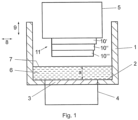
- the device which is located in air or another gas atmosphere, has a tank 1, the tank bottom 2 of which is transparent or translucent at least in a partial area 3.
- This partial area 3 of the tank bottom detects at least the extent of an exposure unit 4, which is arranged under the tank bottom 2.
- the exposure unit 4 has a light source (not shown in detail) and a light modulator with which the intensity can be controlled by a control unit and adjusted in a location-selective manner in order to generate an exposure field with the geometry desired for the layer currently to be formed on the tank bottom 2.
- a laser can also be used in the exposure unit, the light beam of which successively scans the exposure field with the desired intensity pattern via a movable mirror controlled by a control unit.
- a construction platform 5 is provided above the tank 1, which is supported by a lifting mechanism (not shown) so that it is held in a height-adjustable manner above the tank bottom 2 in the area above the exposure unit 4.
- the construction platform 5 can also be transparent or translucent.
- the tank 1 contains a bath of highly viscous photopolymerizable material 6.
- the material level 7 of the bath is defined by a suitable element, such as a doctor blade, which applies the material evenly to the tank bottom 2 in a certain material layer thickness a.
- the tank 1 can, for example, be assigned a guide rail on which a carriage is guided so as to be displaceable in the direction of the double arrow 8.
- a drive ensures the back and forth movement of the carriage, which has a holder for a doctor blade.
- the holder has, for example, a guide and a Adjustment device to adjust the squeegee in the direction of the double arrow 9 in the vertical direction. This allows the distance of the lower edge of the squeegee from the bottom 2 of the tank 1 to be adjusted.
- the squeegee is used when the construction platform is as in Fig.1 shown in the raised state, and serves to distribute the material 6 evenly while setting a predetermined layer thickness.
- the layer thickness of the material 6 resulting from the material distribution process is defined by the distance of the lower edge of the squeegee from the bottom 2 of the tank 1.
- the resulting material layer thickness a is greater than the molded body layer thickness b ( Fig.2 ).
- the construction platform 5, on which molded body layers 10', 10" and 10′′′ have already been formed is, as in Fig.2 shown, is lowered in a controlled manner by the lifting mechanism so that the underside of the lowest molded body layer 10′′′ first touches the surface of the material bath 6 at height a, then dips in and approaches the tank bottom 2 to such an extent that exactly the desired molded body layer thickness b remains between the underside of the lowest molded body layer 10"' and the tank bottom 2.
- molded body layers 10 made of photopolymerizable material are then repeated several times in order to obtain further molded body layers 10 made of photopolymerizable material.
- the distance between the underside of the last formed molded body layer 10 and the tank bottom 2 is set to the desired molded body layer thickness b and the photopolymerizable material is then cured in a location-selective manner in the desired manner.
- air bubbles can form in the photopolymerizable material in several ways, which are described below with reference to Fig.4 to be discribed.
- the first possibility for the formation of air bubbles occurs during contact of the material bath 6 by the construction platform 5 or the lowest mold layer 10 (hereinafter referred to as "contacting"), as can be seen from Fig.4
- the contacting does not initially take place over the entire surface of the lowest molded body layer 10, but only at point 13 (hereinafter referred to as the contact point) of the smallest distance x between the lowest molded body layer 10 and the material surface 7.
- the contacting process is affected by unwanted irregularities in the material surface ( Fig. 4a ) and in the construction platform 5 or the lowest mold layer 10 ( Fig.
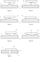
- Fig.5 shows this case, where for the sake of simplicity and without loss of generality a two-dimensional system is assumed.
- Fig. 5a shows the last formed mold layer 10 of the unfinished mold 11, to which uncured material 12 adheres, and the material 6 in the tub 1.
- the uncured material 12 simultaneously forms two contact points 13 ( Fig. 5b ), which encloses a gas bubble 14. If the construction platform 5 is lowered further ( Fig. 5c ), the gas bubble is also pushed downwards and touches both the tank bottom 2 and the building platform 5 or the lowest mold layer 10.
- each contact surface has a limited extent and new contact points can arise outside of it at any time while the component is lowered further.
- the probability of air inclusions is lower if the construction platform 5 or the lowest molded body layer 10 and the surface 7 of the material 6 are not parallel when they touch, which significantly increases control over the position of the contact points and the time at which they begin.
- This can be implemented in various forms, e.g. by means of a trough 1 or construction platform 5 that is adjustable in angle, height or shape. In a preferred embodiment of the invention, however, this is achieved by means of an inclined or uneven material surface 7, which is mechanically easier to implement and offers more options, e.g. a wavy surface 7 or an inclined surface 7.
- an appropriate material surface 7 it is possible to ensure that a single contact point spreads successively over the entire component surface and no further contact points arise.
- Fig. 6a shows an embodiment with such a material layer 6, the layer thickness a of which varies depending on location or in the lateral direction.
- the material surface 7 forms an inclined plane and the first contact point 13 is created at the highest point of the inclined plane, whereby the first contact point 13 spreads successively over the component surface.
- Fig. 6b shows an analogous design in which the material surface is pyramid- or cone-shaped.
- the air bubbles that arise when the material bath 6 is touched by the construction platform 5 or the lowest mold layer 10 can be removed by partially pressing out the material 6 from the side beneath the construction platform 5 or the lowest mold layer 10, which is explained below using Fig.7
- the lowest mold layer 10 contacts the material when the construction platform 5 is lowered at the height a and, as it is lowered further to the mold layer thickness b, exerts force on the material 6 below, whereby it is pushed out laterally from the gap 15 between the lowest mold layer 10 and the tank bottom 2. If there are air bubbles 14 in the material, they are carried along by the material flow.
- Fig. 7a it is evident that an air bubble 14 has been enclosed.
- the material flow takes the bubble 14 to the edge of the component ( Fig. 7b ), where it rises to the material surface 7 ( Fig. 7c ) and is no longer in the area to be exposed.
- Fig. 8a shows a molded body layer of a cylindrical molded body 11, specifically a circle with radius R1.
- the arrows illustrate the different path lengths that a bubble 14, which is created at points A, B, C or D, has to travel.
- bubbles E and F ( Fig. 8b ), which can occur in a cylindrical molded body with radius R2 smaller than R1, shorter path lengths and thus a smaller material layer thickness is necessary to produce sufficient flow.
- Recesses also make the removal of air bubbles 14 more difficult due to the fact that an air bubble 14 can move away from an edge delimiting a recess 16 on the Component 11 only releases under the influence of force due to surface tension.
- the amount of material pressed out or pressed into holes 16 in the lowest mold body layer 10 as well as the material flow disappear when the layer thickness a of the material layer 6 and the layer thickness b of the mold body layer are selected so that a b, and increase with increasing material layer thickness a.
- An increase in the material layer thickness a therefore ensures a reduced amount of air bubbles 14 after the construction platform 5 is lowered.
- the lowering of the construction platform 5 or the unfinished molded body 11 can only be carried out slowly with high material layer thicknesses a, since the material 6 must be given enough time to flow out of the gap 15 between the construction platform 5 or the lowest molded body layer 10 and the tank bottom 2.
- This waiting time increases with increasing material layer thickness a and leads to a significant extension of the overall process time.
- the material layer thickness a is determined once and left the same throughout the entire construction process of the molded body in question.
- the invention provides that the material layer thickness a is adjusted at least once during the construction process, in particular with a view to optimizing the bubble displacement while simultaneously minimizing the layer thickness in order to avoid the disadvantages of large layer thicknesses described as far as possible. It is preferably provided that an optimal layer thickness a of the material layer 6 is newly determined for each molded body layer to be exposed, so that the material flow that occurs when the component 11 is immersed in the material 6 is sufficient to ensure that the gas bubbles 14 are displaced from the area to be exposed.
- Fig. 10a low material layer thickness a
- Fig. 10b higher material layer thickness a
- the last formed layer 10′′′ owns in Fig. 10a a small area (extension y) and in Fig. 10b a large area (extension z).
- the material layer thickness a is therefore such that in the case of Fig. 10a can be chosen smaller than in the case of Fig. 10b to create the flow necessary for bubble displacement.
- the necessary material layer thickness is estimated by determining the geometrically determined material flow and the geometrically determined path lengths of possibly present bubbles, usually by a connected computing unit.
- the material layer thickness a is increased.
- the material layer thickness a depends on the area of the previously formed molded body layer n, where n represents a variable for the layer number.
- n represents a variable for the layer number.
- Fig. 11 a preferred linear relationship between the area A of the preceding molded body layer and the material layer thickness a is shown.
- the material layer thickness a(n) for a given layer n is not constant, but is laterally location-dependent, i.e. a(n,x,y). This can have various positive effects, as explained below.
- the material layer thickness a at locations where bubbles with a long displacement path length potentially form is increased compared to the rest of the material layer 6 in order to ensure a larger material flow locally.
- Fig. 12 shows an increased material layer thickness a' in the center of a circular material layer 6.
- Fig. 6a shows a design with location-dependent material layer thickness a, in which the material surface 7 forms an inclined plane and thus the first contact point 13 is created at the highest point of the inclined plane and spreads successively over the component surface.
- Fig. 6b shows an analogous design in which the material surface is pyramid- or cone-shaped.
- material is essentially only applied to the areas to be exposed in order to minimize the impairment of the material by scattered light.
- Fig. 13 the next layer 10′′′ to be exposed as well as the material layer 6 approximately present in this area are shown.
- an adjustable element such as a doctor blade or an adjustable tank 1, is preferred, which applies the material before the exposure of the mold layer n.
Landscapes
- Chemical & Material Sciences (AREA)
- Engineering & Computer Science (AREA)
- Materials Engineering (AREA)
- Manufacturing & Machinery (AREA)
- Physics & Mathematics (AREA)
- Optics & Photonics (AREA)
- Mechanical Engineering (AREA)
Claims (12)
- Procédé de construction en couches d'un corps formé à partir d'un matériau photopolymérisable, à savoir une résine avec une charge céramique, dans lequel des couches de corps formé sont formées successivement les unes sur les autres, en formant dans chaque cas une couche de matériau d'épaisseur prédéfinie du matériau photopolymérisable dans une cuve et la plate-forme de construction ou le corps formé au moins partiellement construit sur la plate-forme de construction est abaissé dans la couche de matériau, de sorte qu'une couche du matériau photopolymérisable se forme entre la plate-forme de construction ou le corps formé et le fond de la cuve, qui est en particulier durcie de manière sélective par irradiation à travers le fond de la cuve pour former la forme souhaitée de la couche de corps formé, l'épaisseur prédéfinie (a) de la couche de matériau (6) étant variée au moins une fois pendant la construction du corps formé (11), de sorte que l'épaisseur (a) de la couche de matériau (6) pour la formation d'au moins une première couche de corps formé est choisie différemment de l'épaisseur de la couche de matériau pour la formation d'au moins une autre couche de corps formé, l'épaisseur prédéfinie de la couche de matériau (a) étant variée en fonction d'une valeur calculée de la longueur du trajet de déplacement de bulles (14) se formant à l'interface entre la plate-forme de construction (5) ou le corps formé (11) et le matériau photopolymérisable.
- Procédé selon la revendication 1, caractérisé en ce que la plate-forme de construction (5) est soulevée après l'étape de durcissement et est à nouveau abaissée dans la cuve (1) pour former la prochaine couche de corps formé (10), après que du matériau a été amené sous la plate-forme de construction (5) soulevée pour former la couche de matériau (6).
- Procédé selon la revendication 1 ou 2, caractérisé en ce que l'apport de matériau est effectué par distribution de matériau à l'aide d'une racle, l'épaisseur prédéfinie (a) de la couche de matériau (6) étant réglée par réglage de la distance entre le bord inférieur de la racle et le fond de la cuve (2).
- Procédé selon l'une quelconque des revendications 1 à 3, caractérisé en ce que l'épaisseur prédéfinie de la couche de matériau (a) varie en fonction de la surface de la couche de corps formé précédente (10).
- Procédé selon l'une quelconque des revendications 1 à 4, caractérisé en ce que l'épaisseur prédéfinie de la couche de matériau (a) est recalculée pour la fabrication de chaque couche de corps formé (10).
- Procédé selon l'une quelconque des revendications 1 à 5, caractérisé en ce qu'au moins une couche de matériau (6) présente une variation d'épaisseur dans la direction latérale.
- Procédé selon la revendication 6, caractérisé en ce que la variation d'épaisseur est prévue dans une seule extension latérale ou dans deux extensions latérales perpendiculaires l'une à l'autre.
- Procédé selon la revendication 6 ou 7, caractérisé en ce que ladite couche de matériau (6) présente une zone en forme de rampe.
- Procédé selon la revendication 6 ou 7, caractérisé en ce que ladite couche de matériau (6) présente une zone en forme de cône.
- Dispositif pour mettre en oeuvre le procédé selon l'une quelconque des revendications 1 à 9, comprenant- une cuve (1) avec un fond (2) au moins partiellement transparent à la lumière, dans laquelle du matériau photopolymérisable peut être introduit,- une racle maintenue à une hauteur réglable au-dessus du fond de la cuve (2) pour former une couche de matériau (6) sur le fond de la cuve (2), une unité de réglage étant prévue pour le réglage en hauteur,- une plate-forme de construction (5), qui est maintenue à une hauteur réglable au-dessus du fond de la cuve (2),- une unité d'irradiation, qui peut être commandée pour l'irradiation sélective en position d'une couche de corps formé (10) formée entre le dessous de la plate-forme de construction (5) et le fond de la cuve (2),- une mémoire électronique pour un modèle tridimensionnel virtuel des couches de corps formé (10) et du corps formé (11) construit à partir de celles-ci,- une unité de commande, à laquelle le modèle virtuel des couches de corps formé est fourni et qui est conçue pour polymériser des couches de corps formé (10) superposées sur la plate-forme de construction (5) avec une géométrie prédéfinie lors de chaque étape d'irradiation successive par commande de l'unité d'irradiation et, en fonction de la géométrie de la couche de corps formé (10) respective, pour calculer une valeur cible de l'épaisseur de la couche de matériau (a) et pour générer un signal de commande pour l'unité de réglage associée à la racle afin de régler l'épaisseur de la couche de matériau (a) conformément à la valeur cible, l'unité de commande étant conçue pour calculer l'épaisseur de la couche de matériau (a) en fonction d'une valeur calculée de la longueur du trajet de déplacement de bulles (14) se formant à l'interface entre la plate-forme de construction (5) ou le corps formé (11) et le matériau photopolymérisable.
- Dispositif selon la revendication 10, caractérisé en ce que la valeur cible de l'épaisseur de la couche de matériau (a) est calculée en fonction de la surface de la couche de corps formé précédente (10).
- Dispositif selon la revendication 10 ou 11, caractérisé en ce que la valeur cible de l'épaisseur de la couche de matériau (a) est recalculée pour la fabrication de chaque couche de corps formé (10).
Applications Claiming Priority (2)
| Application Number | Priority Date | Filing Date | Title |
|---|---|---|---|
| ATA205/2015A AT517049A1 (de) | 2015-04-02 | 2015-04-02 | Verfahren zum schichtweisen Aufbau eines Formkörpers |
| PCT/AT2016/000032 WO2016154645A1 (fr) | 2015-04-02 | 2016-03-30 | Procédé et dispositif de fabrication additive d'un corps |
Publications (2)
| Publication Number | Publication Date |
|---|---|
| EP3277482A1 EP3277482A1 (fr) | 2018-02-07 |
| EP3277482B1 true EP3277482B1 (fr) | 2024-06-26 |
Family
ID=55660996
Family Applications (1)
| Application Number | Title | Priority Date | Filing Date |
|---|---|---|---|
| EP16714209.0A Active EP3277482B1 (fr) | 2015-04-02 | 2016-03-30 | Procédé et dispositif de fabrication additive d'un corps |
Country Status (5)
| Country | Link |
|---|---|
| US (1) | US10967564B2 (fr) |
| EP (1) | EP3277482B1 (fr) |
| CN (1) | CN107848199B (fr) |
| AT (1) | AT517049A1 (fr) |
| WO (1) | WO2016154645A1 (fr) |
Families Citing this family (7)
| Publication number | Priority date | Publication date | Assignee | Title |
|---|---|---|---|---|
| CN107750200B (zh) * | 2015-02-26 | 2021-03-30 | 康宁股份有限公司 | 用于从无机材料制作透明3d部件的增材制造方法 |
| AT517044A1 (de) * | 2015-04-02 | 2016-10-15 | Lithoz Gmbh | Verfahren zum schichtweisen Aufbau eines Formkörpers |
| US10786334B2 (en) | 2018-06-12 | 2020-09-29 | Lightforce Orthodontics, Inc. | Ceramic processing and design for the direct manufacture of customized labial and lingual orthodontic clear aligner attachments |
| US11851379B2 (en) | 2018-07-03 | 2023-12-26 | Corning Incorporated | Selective masking and plugging of honeycomb bodies |
| US11155028B1 (en) | 2020-04-24 | 2021-10-26 | Sprintray Inc. | Apparatus and method for three-dimensional printing |
| US11651873B2 (en) | 2021-06-25 | 2023-05-16 | Greatbatch Ltd. | Three-dimensional printed feedthroughs for implantable medical devices |
| US11498117B1 (en) | 2021-11-12 | 2022-11-15 | General Electric Company | Method and apparatus for supporting wax pattern during investment casting |
Family Cites Families (8)
| Publication number | Priority date | Publication date | Assignee | Title |
|---|---|---|---|---|
| EP0354637B1 (fr) | 1988-04-18 | 1997-06-25 | 3D Systems, Inc. | Conversion stéreolithographique de données par CAD/CAM |
| US20010048183A1 (en) * | 2000-05-31 | 2001-12-06 | Sanyo Electric Co., Ltd | Optical shaping apparatus and optical shaping process |
| JP5480907B2 (ja) | 2008-10-20 | 2014-04-23 | イフォクレール ヴィヴァデント アクチェンゲゼルシャフト | 層内で物体を構築するために光重合性材料を処理するためのデバイスおよび方法 |
| ES2424738T3 (es) * | 2011-03-29 | 2013-10-08 | Ivoclar Vivadent Ag | Procedimiento para la formación en capas de un cuerpo moldeado de material foto polimerizable de alta viscosidad |
| ITVI20110099A1 (it) | 2011-04-20 | 2012-10-21 | Dws Srl | Metodo per la produzione di un oggetto tridimensionale e macchina stereolitografica impiegante tale metodo |
| AU2012300179B2 (en) | 2011-08-20 | 2017-08-03 | Zydex Pty Ltd | Apparatus and method for making an object |
| AT515138B1 (de) * | 2013-11-22 | 2016-05-15 | Tech Universität Wien | Vorrichtung zum Verarbeiten von photopolymerisierbarem Material zum schichtweisen Aufbau eines Formkörpers |
| AT517044A1 (de) * | 2015-04-02 | 2016-10-15 | Lithoz Gmbh | Verfahren zum schichtweisen Aufbau eines Formkörpers |
-
2015
- 2015-04-02 AT ATA205/2015A patent/AT517049A1/de not_active Application Discontinuation
-
2016
- 2016-03-30 US US15/563,449 patent/US10967564B2/en active Active
- 2016-03-30 CN CN201680032033.1A patent/CN107848199B/zh active Active
- 2016-03-30 EP EP16714209.0A patent/EP3277482B1/fr active Active
- 2016-03-30 WO PCT/AT2016/000032 patent/WO2016154645A1/fr active Application Filing
Also Published As
| Publication number | Publication date |
|---|---|
| US10967564B2 (en) | 2021-04-06 |
| WO2016154645A1 (fr) | 2016-10-06 |
| CN107848199A (zh) | 2018-03-27 |
| US20180117835A1 (en) | 2018-05-03 |
| AT517049A1 (de) | 2016-10-15 |
| EP3277482A1 (fr) | 2018-02-07 |
| CN107848199B (zh) | 2020-09-08 |
Similar Documents
| Publication | Publication Date | Title |
|---|---|---|
| EP3277482B1 (fr) | Procédé et dispositif de fabrication additive d'un corps | |
| EP3277481B1 (fr) | Procédé et dispositif de fabrication additive d'un corps | |
| EP3710182B1 (fr) | Éclairage sélectif par couche dans la zone en surplomb lors de la fabrication additive | |
| EP2505341B1 (fr) | Procédé de fabrication par couches d'un objet en matériau photopolymérisable hautement visqueux | |
| EP3285988B1 (fr) | Procédé et dispositif de fabrication d'un objet tridimensionnel | |
| EP2864108B1 (fr) | Dispositif et procédé de fabrication par couches d'un objet tridimensionnel | |
| EP3099469B1 (fr) | Procédé et dispositif de commande améliorée de l'apport d'énergie dans un procédé de construction additive par génération de couches | |
| EP0738584B1 (fr) | Dispositif et procédé pour la fabrication d'un objet tridimensionnel | |
| EP2083992B1 (fr) | Procédé génératif continu et dispositif pour la fabrication d'un objet tridimensionnel | |
| WO2001072501A1 (fr) | Procede et dispositif de production de composants realises dans des materiaux durcissables a la lumiere | |
| DE102012021284B4 (de) | Vorrichtung und Verfahren zur schichtweisen Herstellung von Bauteilen mittels Photopolymerisation | |
| EP2643112B1 (fr) | Procédé de fabrication d'une pièce par couches | |
| EP3579996A1 (fr) | Stratégie d'exposition dans des systèmes de fabrication additive (am) à faisceaux multiples | |
| EP3747634B1 (fr) | Procédé de fabrication d'au moins un composant par impression 3d et imprimante 3d | |
| DE102009035258A1 (de) | Verfahren zum Herstellen eines dreidimensionalen Objektes | |
| EP4008523B1 (fr) | Procédé et dispositif de construction en couches d'un composant en matière photopolymerisable | |
| DE102018125853A1 (de) | Vorrichtung zur additiven Fertigung | |
| EP4238741A1 (fr) | Procédé de fabrication additive d'un composant à l'aide d'au moins une chambre volumique à remplir de matériau de remplissage | |
| DE102020126764A1 (de) | Additive fertigungseinrichtung, verfahren sowie medizinprodukt hierzu | |
| DE102020120319A1 (de) | Verfahren und Vorrichtung zur additiven Herstellung eines Werkstücks | |
| DE102017205903B4 (de) | Verfahren und Vorrichtung zur Herstellung eines Bauteils aus mindestens zwei unterschiedlichen Materialien durch Drucken im Pulverbettverfahren | |
| DE4110903C2 (fr) |
Legal Events
| Date | Code | Title | Description |
|---|---|---|---|
| STAA | Information on the status of an ep patent application or granted ep patent |
Free format text: STATUS: THE INTERNATIONAL PUBLICATION HAS BEEN MADE |
|
| PUAI | Public reference made under article 153(3) epc to a published international application that has entered the european phase |
Free format text: ORIGINAL CODE: 0009012 |
|
| STAA | Information on the status of an ep patent application or granted ep patent |
Free format text: STATUS: REQUEST FOR EXAMINATION WAS MADE |
|
| 17P | Request for examination filed |
Effective date: 20170921 |
|
| AK | Designated contracting states |
Kind code of ref document: A1 Designated state(s): AL AT BE BG CH CY CZ DE DK EE ES FI FR GB GR HR HU IE IS IT LI LT LU LV MC MK MT NL NO PL PT RO RS SE SI SK SM TR |
|
| AX | Request for extension of the european patent |
Extension state: BA ME |
|
| DAV | Request for validation of the european patent (deleted) | ||
| DAX | Request for extension of the european patent (deleted) | ||
| STAA | Information on the status of an ep patent application or granted ep patent |
Free format text: STATUS: EXAMINATION IS IN PROGRESS |
|
| 17Q | First examination report despatched |
Effective date: 20200212 |
|
| STAA | Information on the status of an ep patent application or granted ep patent |
Free format text: STATUS: EXAMINATION IS IN PROGRESS |
|
| REG | Reference to a national code |
Ref country code: DE Ref legal event code: R079 Ref document number: 502016016596 Country of ref document: DE Free format text: PREVIOUS MAIN CLASS: B29C0067000000 Ipc: B29C0064129000 Ref country code: DE Ref legal event code: R079 Free format text: PREVIOUS MAIN CLASS: B29C0067000000 Ipc: B29C0064129000 |
|
| GRAP | Despatch of communication of intention to grant a patent |
Free format text: ORIGINAL CODE: EPIDOSNIGR1 |
|
| STAA | Information on the status of an ep patent application or granted ep patent |
Free format text: STATUS: GRANT OF PATENT IS INTENDED |
|
| RIC1 | Information provided on ipc code assigned before grant |
Ipc: B33Y 50/02 20150101ALI20240219BHEP Ipc: B33Y 30/00 20150101ALI20240219BHEP Ipc: B33Y 10/00 20150101ALI20240219BHEP Ipc: B29C 67/00 20170101ALI20240219BHEP Ipc: B29C 64/393 20170101ALI20240219BHEP Ipc: B29C 64/135 20170101ALI20240219BHEP Ipc: B29C 64/129 20170101AFI20240219BHEP |
|
| INTG | Intention to grant announced |
Effective date: 20240314 |
|
| GRAS | Grant fee paid |
Free format text: ORIGINAL CODE: EPIDOSNIGR3 |
|
| GRAA | (expected) grant |
Free format text: ORIGINAL CODE: 0009210 |
|
| STAA | Information on the status of an ep patent application or granted ep patent |
Free format text: STATUS: THE PATENT HAS BEEN GRANTED |
|
| AK | Designated contracting states |
Kind code of ref document: B1 Designated state(s): AL AT BE BG CH CY CZ DE DK EE ES FI FR GB GR HR HU IE IS IT LI LT LU LV MC MK MT NL NO PL PT RO RS SE SI SK SM TR |
|
| REG | Reference to a national code |
Ref country code: GB Ref legal event code: FG4D Free format text: NOT ENGLISH |
|
| REG | Reference to a national code |
Ref country code: CH Ref legal event code: EP |
|
| REG | Reference to a national code |
Ref country code: DE Ref legal event code: R096 Ref document number: 502016016596 Country of ref document: DE |
|
| U01 | Request for unitary effect filed |
Effective date: 20240723 |