EP3277478B1 - Method of manufacturing a multi-material conveyor component - Google Patents
Method of manufacturing a multi-material conveyor component Download PDFInfo
- Publication number
- EP3277478B1 EP3277478B1 EP16773742.8A EP16773742A EP3277478B1 EP 3277478 B1 EP3277478 B1 EP 3277478B1 EP 16773742 A EP16773742 A EP 16773742A EP 3277478 B1 EP3277478 B1 EP 3277478B1
- Authority
- EP
- European Patent Office
- Prior art keywords
- substrate
- thermoformable
- thermoformable substrate
- mold
- mold cavity
- Prior art date
- Legal status (The legal status is an assumption and is not a legal conclusion. Google has not performed a legal analysis and makes no representation as to the accuracy of the status listed.)
- Active
Links
Images



Classifications
-
- B—PERFORMING OPERATIONS; TRANSPORTING
- B29—WORKING OF PLASTICS; WORKING OF SUBSTANCES IN A PLASTIC STATE IN GENERAL
- B29C—SHAPING OR JOINING OF PLASTICS; SHAPING OF MATERIAL IN A PLASTIC STATE, NOT OTHERWISE PROVIDED FOR; AFTER-TREATMENT OF THE SHAPED PRODUCTS, e.g. REPAIRING
- B29C45/00—Injection moulding, i.e. forcing the required volume of moulding material through a nozzle into a closed mould; Apparatus therefor
- B29C45/14—Injection moulding, i.e. forcing the required volume of moulding material through a nozzle into a closed mould; Apparatus therefor incorporating preformed parts or layers, e.g. injection moulding around inserts or for coating articles
- B29C45/14549—Coating rod-like, wire-like or belt-like articles
-
- B—PERFORMING OPERATIONS; TRANSPORTING
- B29—WORKING OF PLASTICS; WORKING OF SUBSTANCES IN A PLASTIC STATE IN GENERAL
- B29C—SHAPING OR JOINING OF PLASTICS; SHAPING OF MATERIAL IN A PLASTIC STATE, NOT OTHERWISE PROVIDED FOR; AFTER-TREATMENT OF THE SHAPED PRODUCTS, e.g. REPAIRING
- B29C45/00—Injection moulding, i.e. forcing the required volume of moulding material through a nozzle into a closed mould; Apparatus therefor
- B29C45/14—Injection moulding, i.e. forcing the required volume of moulding material through a nozzle into a closed mould; Apparatus therefor incorporating preformed parts or layers, e.g. injection moulding around inserts or for coating articles
- B29C45/14311—Injection moulding, i.e. forcing the required volume of moulding material through a nozzle into a closed mould; Apparatus therefor incorporating preformed parts or layers, e.g. injection moulding around inserts or for coating articles using means for bonding the coating to the articles
-
- B—PERFORMING OPERATIONS; TRANSPORTING
- B65—CONVEYING; PACKING; STORING; HANDLING THIN OR FILAMENTARY MATERIAL
- B65G—TRANSPORT OR STORAGE DEVICES, e.g. CONVEYORS FOR LOADING OR TIPPING, SHOP CONVEYOR SYSTEMS OR PNEUMATIC TUBE CONVEYORS
- B65G17/00—Conveyors having an endless traction element, e.g. a chain, transmitting movement to a continuous or substantially-continuous load-carrying surface or to a series of individual load-carriers; Endless-chain conveyors in which the chains form the load-carrying surface
- B65G17/30—Details; Auxiliary devices
- B65G17/38—Chains or like traction elements; Connections between traction elements and load-carriers
- B65G17/40—Chains acting as load-carriers
-
- B—PERFORMING OPERATIONS; TRANSPORTING
- B65—CONVEYING; PACKING; STORING; HANDLING THIN OR FILAMENTARY MATERIAL
- B65G—TRANSPORT OR STORAGE DEVICES, e.g. CONVEYORS FOR LOADING OR TIPPING, SHOP CONVEYOR SYSTEMS OR PNEUMATIC TUBE CONVEYORS
- B65G17/00—Conveyors having an endless traction element, e.g. a chain, transmitting movement to a continuous or substantially-continuous load-carrying surface or to a series of individual load-carriers; Endless-chain conveyors in which the chains form the load-carrying surface
- B65G17/30—Details; Auxiliary devices
- B65G17/46—Means for holding or retaining the loads in fixed position on the load-carriers, e.g. magnetic
-
- B—PERFORMING OPERATIONS; TRANSPORTING
- B29—WORKING OF PLASTICS; WORKING OF SUBSTANCES IN A PLASTIC STATE IN GENERAL
- B29C—SHAPING OR JOINING OF PLASTICS; SHAPING OF MATERIAL IN A PLASTIC STATE, NOT OTHERWISE PROVIDED FOR; AFTER-TREATMENT OF THE SHAPED PRODUCTS, e.g. REPAIRING
- B29C45/00—Injection moulding, i.e. forcing the required volume of moulding material through a nozzle into a closed mould; Apparatus therefor
- B29C45/14—Injection moulding, i.e. forcing the required volume of moulding material through a nozzle into a closed mould; Apparatus therefor incorporating preformed parts or layers, e.g. injection moulding around inserts or for coating articles
- B29C45/14311—Injection moulding, i.e. forcing the required volume of moulding material through a nozzle into a closed mould; Apparatus therefor incorporating preformed parts or layers, e.g. injection moulding around inserts or for coating articles using means for bonding the coating to the articles
- B29C2045/14319—Injection moulding, i.e. forcing the required volume of moulding material through a nozzle into a closed mould; Apparatus therefor incorporating preformed parts or layers, e.g. injection moulding around inserts or for coating articles using means for bonding the coating to the articles bonding by a fusion bond
-
- B—PERFORMING OPERATIONS; TRANSPORTING
- B29—WORKING OF PLASTICS; WORKING OF SUBSTANCES IN A PLASTIC STATE IN GENERAL
- B29C—SHAPING OR JOINING OF PLASTICS; SHAPING OF MATERIAL IN A PLASTIC STATE, NOT OTHERWISE PROVIDED FOR; AFTER-TREATMENT OF THE SHAPED PRODUCTS, e.g. REPAIRING
- B29C2791/00—Shaping characteristics in general
- B29C2791/001—Shaping in several steps
-
- B—PERFORMING OPERATIONS; TRANSPORTING
- B29—WORKING OF PLASTICS; WORKING OF SUBSTANCES IN A PLASTIC STATE IN GENERAL
- B29C—SHAPING OR JOINING OF PLASTICS; SHAPING OF MATERIAL IN A PLASTIC STATE, NOT OTHERWISE PROVIDED FOR; AFTER-TREATMENT OF THE SHAPED PRODUCTS, e.g. REPAIRING
- B29C51/00—Shaping by thermoforming, i.e. shaping sheets or sheet like preforms after heating, e.g. shaping sheets in matched moulds or by deep-drawing; Apparatus therefor
- B29C51/08—Deep drawing or matched-mould forming, i.e. using mechanical means only
- B29C51/082—Deep drawing or matched-mould forming, i.e. using mechanical means only by shaping between complementary mould parts
-
- B—PERFORMING OPERATIONS; TRANSPORTING
- B29—WORKING OF PLASTICS; WORKING OF SUBSTANCES IN A PLASTIC STATE IN GENERAL
- B29C—SHAPING OR JOINING OF PLASTICS; SHAPING OF MATERIAL IN A PLASTIC STATE, NOT OTHERWISE PROVIDED FOR; AFTER-TREATMENT OF THE SHAPED PRODUCTS, e.g. REPAIRING
- B29C51/00—Shaping by thermoforming, i.e. shaping sheets or sheet like preforms after heating, e.g. shaping sheets in matched moulds or by deep-drawing; Apparatus therefor
- B29C51/26—Component parts, details or accessories; Auxiliary operations
- B29C51/266—Auxiliary operations after the thermoforming operation
-
- B—PERFORMING OPERATIONS; TRANSPORTING
- B29—WORKING OF PLASTICS; WORKING OF SUBSTANCES IN A PLASTIC STATE IN GENERAL
- B29K—INDEXING SCHEME ASSOCIATED WITH SUBCLASSES B29B, B29C OR B29D, RELATING TO MOULDING MATERIALS OR TO MATERIALS FOR MOULDS, REINFORCEMENTS, FILLERS OR PREFORMED PARTS, e.g. INSERTS
- B29K2023/00—Use of polyalkenes or derivatives thereof as moulding material
- B29K2023/04—Polymers of ethylene
- B29K2023/06—PE, i.e. polyethylene
- B29K2023/0608—PE, i.e. polyethylene characterised by its density
- B29K2023/065—HDPE, i.e. high density polyethylene
-
- B—PERFORMING OPERATIONS; TRANSPORTING
- B29—WORKING OF PLASTICS; WORKING OF SUBSTANCES IN A PLASTIC STATE IN GENERAL
- B29L—INDEXING SCHEME ASSOCIATED WITH SUBCLASS B29C, RELATING TO PARTICULAR ARTICLES
- B29L2031/00—Other particular articles
- B29L2031/709—Articles shaped in a closed loop, e.g. conveyor belts
- B29L2031/7092—Conveyor belts
Definitions
- the invention relates generally to power-driven conveyors and, more particularly, to components in a conveyor system formed by two or more materials bonded together.
- Many conveyor components such as belt modules that link together to form a conveyor belt, position limiters, wear strips and sprockets are injection molded out of a thermoplastic polymer material to form a rigid body.
- JP 2003 127170 A discloses a method for manufacturing a decorative molded article.
- US 2007/284225 A1 discloses a module for chains or belts that is molded from a plastic compound containing a magnetizable element.
- US 5 361 893 A discloses a plastic conveyor belt system providing high frictional surface contact between the conveyor work surface and the load carried by the conveyor.
- the present invention provides a method of manufacturing a conveyor component, in accordance with claim 1.
- thermoformable material to an injection moldable material to form a conveyor component.
- the invention will be described below relative to certain illustrative embodiments, though the invention is not limited to the illustrative embodiments.
- FIG. 1 shows an embodiment of a conveyor component 10 comprising multiple materials chemically bonded to each other.
- the illustrative conveyor component 10 is a position limiter including a base portion 12 formed of a first material and an upper layer 14 formed of a second material bonded to the first material.
- the illustrative upper layer forms a limiting surface for contacting a conveyor belt to ensure proper engagement between a tooth on the conveyor belt and a sprocket driving the conveyor belt.
- the illustrative base portion 12 is formed of an injection molded material.
- the upper layer 14 comprises a thermoformable material bonded to the injection molded material during a manufacturing process.
- the first material comprises an injection moldable material.
- injection moldable material refers to any suitable material or combination of materials that may be injection molded to form a selected shape. Injection moldable materials are able to transition to molten form when heated. Examples include, but are not limited to thermoplastic polymer materials, such as polypropylene, polyethylene, acetal, or composite polymers.
- the base portion 12 includes a snap clamp 13 for mounting the conveyor component to a shaft of a conveyor frame, as described in U.S. Patent Application Serial Number 14/602,455, field January 22, 2015 and entitled "Snap-On Position Limiter for a Conveyor Belt", the contents of which are herein incorporated by reference.
- thermoformable material refers to any suitable material or combination of materials that is thermoformable, i.e., able to be formed by heat and-or compression.
- a thermoformable material does not transition to molten form when heated and retains a solid, though malleable form. Examples include, but are not limited to ultra-high-molecular-weight polyethylene (UHMW), ceramic-impregnated plastic, and others known in the art.
- UHMW ultra-high-molecular-weight polyethylene
- ceramic-impregnated plastic An example of a ceramic-impregnated thermoformable material is Ceram P ® available from Quadrant EPP AG Corporation of Lenzburg, Switzerland.
- the upper layer 14 forms a limiting surface 18 for guiding a conveyor belt relative to a sprocket.
- the limiting surface 18 of the upper layer has a low coefficient of friction to facilitate its limiting function.
- the base portion 12 is formed of a stronger material to withstand certain forces and the limiting surface 18 is formed of material with a low coefficient of friction to facilitate the limiting function.
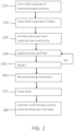
- FIG. 2 illustrates the steps involved in manufacturing a conveyor component, such as the conveyor component 10 of FIG. 1 , having a base portion 12 formed of an injection moldable material and an upper layer 14 comprising a thermoformable material bonded to the injection molded material.
- FIG. 3 is a diagram of a portion of a molding machine used in the process of FIG. 2 .
- the molding machine 300 uses an injection mold including a first mold half, shown as a bottom mold 310.
- the bottom mold 310 includes a mold cavity 311 forming a mold surface 320 that defines the upper surface 18 of the final conveyor component 10.
- the machine 300 includes holders for holding a substrate 314 of a thermoformable material.
- the holders 340 comprise spring-loaded pins forming an initial seat for the substrate 314 and extending through the bottom mold.
- the pins 340 initially hold the substrate above the mold cavity 311.
- the machine also includes a heating mechanism 360 for heating the thermoformable substrate.
- a "draft" insert and-or substrate 314 of a thermoformable material is formed.
- the draft substrate may be stamped, cut or otherwise formed into a basic outline shape through any suitable means known in the art.
- the draft insert/substrate could be a simple flat piece sized to a desired size, or could be a more complicated substrate of any size or shape.
- the draft substrate 314 is cut to about the size of the mold surface 320 in the mold cavity 311.
- the draft substrate has a -0to+15% tolerance to allow slight expansion to cover the mold surface 320. If necessary, heat may be applied to form the draft substrate 314.
- the draft substrate 314 has a first surface 318 that forms the limiting surface 18 of the finalized position limiter and an opposite second surface 316 that forms a bonding surface that bonds the upper layer 14 to the base portion 12.
- the draft substrate 314 may have any suitable thickness.
- the draft substrate is inserted in a holder 340.
- the illustrative holder comprises spring-loaded pins inserted in the bottom mold 310 and extending from the top surface thereof. The pins form a seat for holding the draft substrate 314 above the mold cavity 311.
- a heating mechanism 360 pushes down on the draft substrate 314 to preheat and shape the substrate 314.
- the illustrative heat and pressure mechanism 360 comprises a piece of hardened steel shaped to the final form of the layer 14.
- the heating mechanism presses the draft substrate 314 into the mold cavity 311 while applying heat to the thermoformable material.
- the illustrative heating mechanism 360 provides about 2000 watts of heat energy, though the invention is not so limited.
- the heat and pressure makes the substrate sufficiently malleable to conform to the shape of the mold surface 320, resulting in a shaped substrate 314', shown in FIG. 4 , having the shape of the final upper layer of the conveyor component 10. If the draft substrate 314 is already in a desired form, little pressure is applied so that the shape does not substantially change.
- infrared energy can be used to heat the draft substrate.
- Other suitable means for preparing the draft substrate for adhesion can be used.
- the heating mechanism 360 continues to apply heat and pressure to the shaped substrate 314' until the shaped substrate 314' is ready for bonding with an injection molded portion in step 350.
- the heat and pressure are uniformly applied to the bonding surface 316 of the substrate.
- the shaped substrate 314' is in a bondable state when the bonding surface 316' is tacky or adhesive while the opposite surface 318 remains smooth and undeformed, or as close to the original surface finish as possible. In the bondable state, the molecules on the bonding surface 316' are open and ready to chemically bond with another material.
- the heating mechanism is applied until the shaped bonding surface 316' reaches a temperature of between about 200 ° C (392°F) and about 204.5 ° C (400°F).
- the heating mechanism is removed before the opposite surface 318 reaches about 200 ° C (392°F).
- a "ready" bonding surface for UHMW will become clear, indicative of a bondable state, while the opposite side remains opaque, as shown in FIG. 4 .
- the substrate 314' is ready for bonding when the transition 319 between the bondable material 316' and the smooth material 318' is in the middle of the substrate 314', as shown in FIG. 4 .
- the temperature of the heating mechanism 360 is set to 260 ° C (500°F) to provide a heating mechanism surface temperature of between about 200 ° C (392°F) and about 204.5 ° C (400°F). While the illustrative heating mechanism 360 is a direct contact metal material form with heater cartridges installed thereon, the invention is not so limited. The heating mechanism 360 may alternatively heat the thermoformable material through an indirect stream of hot air directed at the thermoformable material or through other means known in the art.
- thermoformable material The actual temperature, pressure and time involved in getting the thermoformable material into a bondable state vary depending on the thermoformable material.
- the draft substrate 314 may expand in one or more directions, trapping itself within the mold cavity 311.
- the manufacturing process employs a heat transmitting layer 350 between the substrate 314 and the heating mechanism 360.
- the heat transmitting layer 350 transfers heat from the heating mechanism but prevents the eventually tacky material in the substrate 314 from sticking to the heating mechanism 360.
- Any suitable material may be used to form the heat transmitting layer.
- the heat transmitting layer comprises a non-stick surface coating, such as polytetrafluoroethylene and others known in the art.
- the heating mechanism 360 is retracted from the ready substrate 314' in step 260. If a heat transmitting layer 350 is used, it is also removed.
- An upper mold half (not shown) immediately mates with the bottom mold 310 to close the mold in step 270.
- step 280 injection molding of the base portion 12 commences.
- the mold is preferably closed and injection molding to commences while the substrate 314' is still in the bondable state.
- Step 280 involves injecting molten injection moldable material into the closed mold in which the ready substrate 314' is contained.
- the gates on the mold for the molten material are located to push the substrate 314' against the surface 320.
- the injection pressure is directed towards the adhesive surface 316' and holds the substrate in place within the mold.
- the molten injection moldable material contacts the bondable layer 316' of the substrate and the two materials bond and lock onto each other.
- thermoformed substrate 314' is preferably kept to a high enough temperature to continue the bonding process during the cooling of the injection molded portion 12 of the conveyor component. This is done with a variance of tools (for the injection molded portion 12) and/or warming channels in the tool (to keep the non-injection molded substrate 314' to a bondable temperature.
- sonic waves may be transmitted into the mold to enhance the bonding between the substrate 314' and the injection molded material.
- the sonic waves excited the modules to promote bonding.
- Electronic beams and - or radiation may also be used.
- the above-described manufacturing technique may be used for any type of conveyor component that is traditionally injection-molded. Examples include, but are not limited to, sprockets, wear strips, conveyor belt modules, position limiters and other components known in the art.
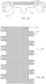
- FIGS. 5A and 5B show another embodiment of a conveyor component 510 comprising a thermoformable material bonded to an injection moldable material.
- the conveyor component 510 is a conveyor belt module including an injection molded base 512 and a thermoformed upper layer 514.
- the thermoformed upper layer 514 is heated and shaped until a bonding surface of the upper layer is in a ready, bonding state in a mold. Then, the material for the base 512 is injected into the mold while the bonding surface is still in the ready, bonding state to form the base portion 512, such that the base portion 512 is bonded to the upper layer 514.
- FIG. 6 shows a conveyor component 610 comprising an injection molded base 612 and a thermoformed upper layer 614 having extensions 625 bonded to the injection molded base 612.
- the conveyor component 610 is formed by heating and shaping the upper layer 614 until a bonding surface of the upper layer is in a ready, bonding state in a mold. Then, the material for the base 612 is injected into the mold while the bonding surface is still in the ready, bonding state to form the base portion 612, such that the base portion 612 is bonded to the upper layer 614.
- the thermoformable portion may form the top of a module, or the bottom of the module.
- a drive bar for a conveyor belt may be thermoformed or compression molded, then a main body of the conveyor belt may be injection molded onto the drive bar.
- a main body may be thermoformed or compression molded, then a drive bar injection molded onto the main body.
- magnetic elements may be inserted in the conveyor component during formation.
- a thermoformable material may be pre-heated and shaped then a magnet loaded onto the thermoformable material, followed by injection molding of another material to seal the magnet between the injection molded material and thermoformable material.
- the magnetic elements sandwiched in a conveyor component may be electromagnets having wires that are exposed to form contact points.
- electromagnets may be embedded in a conveyor belt module between a thermoformable material and an injection molded material with contact points for the electromagnet at the edge of the module.
- a wear strip along the edge of the module may form a full-length contact for powering the electromagnet.
- the contact may power the electromagnet at select times to create a magnetic force to attract items, such as metal pans, to the conveyor belt.
Landscapes
- Engineering & Computer Science (AREA)
- Mechanical Engineering (AREA)
- Manufacturing & Machinery (AREA)
- Injection Moulding Of Plastics Or The Like (AREA)
- Moulds For Moulding Plastics Or The Like (AREA)
Description
- This application claims priority to
US Provisional Patent Application No. 62/140,013, filed March 30, 2015 - The invention relates generally to power-driven conveyors and, more particularly, to components in a conveyor system formed by two or more materials bonded together. Many conveyor components, such as belt modules that link together to form a conveyor belt, position limiters, wear strips and sprockets are injection molded out of a thermoplastic polymer material to form a rigid body.
- Problems abound when attempting to form a conveyor component from multiple materials having different characteristics. It may be difficult to have different materials bond together to form a cohesive, unitary component.
-
JP 2003 127170 A -
US 2007/284225 A1 discloses a module for chains or belts that is molded from a plastic compound containing a magnetizable element. -
US 5 361 893 A discloses a plastic conveyor belt system providing high frictional surface contact between the conveyor work surface and the load carried by the conveyor. - In one aspect, the present invention provides a method of manufacturing a conveyor component, in accordance with claim 1.
- The disclosed systems and methods can be understood with reference to the following drawings. The components in the drawings are not necessarily to scale.
-
FIG. 1 shows a conveyor component formed by bonding a thermoformable material to an injection molded material; -
FIG. 2 shows the manufacturing steps involved in forming a multi-material conveyor component according to an embodiment of the invention; -
FIG. 3 is a schematic diagram of a portion of a molding machine used in the process ofFIG. 2 -
FIG. 4 shows a substrate of a thermoformable material in an intermediate state during the manufacturing process ofFIG. 2 ; -
FIGS. 5A and 5B illustrate another embodiment of a conveyor component manufactured by bonding a thermoformable material in a bondable state to an injection molded material during injection molding; -
FIG. 6 illustrates another embodiment of a conveyor component manufactured by bonding a thermoformable material in a bondable state to an injection molded material during injection molding. - A method of joining a thermoformable material to an injection moldable material to form a conveyor component is provided. The invention will be described below relative to certain illustrative embodiments, though the invention is not limited to the illustrative embodiments.
-
FIG. 1 shows an embodiment of aconveyor component 10 comprising multiple materials chemically bonded to each other. Theillustrative conveyor component 10 is a position limiter including a base portion 12 formed of a first material and anupper layer 14 formed of a second material bonded to the first material. The illustrative upper layer forms a limiting surface for contacting a conveyor belt to ensure proper engagement between a tooth on the conveyor belt and a sprocket driving the conveyor belt. The illustrative base portion 12 is formed of an injection molded material. Theupper layer 14 comprises a thermoformable material bonded to the injection molded material during a manufacturing process. - The first material comprises an injection moldable material. As used herein, "injection moldable material" refers to any suitable material or combination of materials that may be injection molded to form a selected shape. Injection moldable materials are able to transition to molten form when heated. Examples include, but are not limited to thermoplastic polymer materials, such as polypropylene, polyethylene, acetal, or composite polymers.
- The base portion 12 includes a
snap clamp 13 for mounting the conveyor component to a shaft of a conveyor frame, as described inU.S. Patent Application Serial Number 14/602,455, field January 22, 2015 - The second material comprises a themoformable material. As used herein, "thermoformable material" refers to any suitable material or combination of materials that is thermoformable, i.e., able to be formed by heat and-or compression. A thermoformable material does not transition to molten form when heated and retains a solid, though malleable form. Examples include, but are not limited to ultra-high-molecular-weight polyethylene (UHMW), ceramic-impregnated plastic, and others known in the art. An example of a ceramic-impregnated thermoformable material is Ceram P® available from Quadrant EPP AG Corporation of Lenzburg, Switzerland.
- The
upper layer 14 forms alimiting surface 18 for guiding a conveyor belt relative to a sprocket. In one embodiment, thelimiting surface 18 of the upper layer has a low coefficient of friction to facilitate its limiting function. - The ability to use two separate materials with different properties enables different parts of the conveyor component to have optimal properties for that parts' particular function. For example, the base portion 12 is formed of a stronger material to withstand certain forces and the
limiting surface 18 is formed of material with a low coefficient of friction to facilitate the limiting function. -
FIG. 2 illustrates the steps involved in manufacturing a conveyor component, such as theconveyor component 10 ofFIG. 1 , having a base portion 12 formed of an injection moldable material and anupper layer 14 comprising a thermoformable material bonded to the injection molded material. -
FIG. 3 is a diagram of a portion of a molding machine used in the process ofFIG. 2 . Themolding machine 300 uses an injection mold including a first mold half, shown as abottom mold 310. Thebottom mold 310 includes amold cavity 311 forming amold surface 320 that defines theupper surface 18 of thefinal conveyor component 10. Themachine 300 includes holders for holding asubstrate 314 of a thermoformable material. Theholders 340 comprise spring-loaded pins forming an initial seat for thesubstrate 314 and extending through the bottom mold. Thepins 340 initially hold the substrate above themold cavity 311. The machine also includes aheating mechanism 360 for heating the thermoformable substrate. - In a
first step 210, a "draft" (first version or prototype) insert and-orsubstrate 314 of a thermoformable material is formed. The draft substrate may be stamped, cut or otherwise formed into a basic outline shape through any suitable means known in the art. The draft insert/substrate could be a simple flat piece sized to a desired size, or could be a more complicated substrate of any size or shape. In the illustrative embodiment, thedraft substrate 314 is cut to about the size of themold surface 320 in themold cavity 311. Preferably, the draft substrate has a -0to+15% tolerance to allow slight expansion to cover themold surface 320. If necessary, heat may be applied to form thedraft substrate 314. Thedraft substrate 314 has afirst surface 318 that forms thelimiting surface 18 of the finalized position limiter and an oppositesecond surface 316 that forms a bonding surface that bonds theupper layer 14 to the base portion 12. Thedraft substrate 314 may have any suitable thickness. - In
step 220, the draft substrate is inserted in aholder 340. The illustrative holder comprises spring-loaded pins inserted in thebottom mold 310 and extending from the top surface thereof. The pins form a seat for holding thedraft substrate 314 above themold cavity 311. - In
step 230, aheating mechanism 360 pushes down on thedraft substrate 314 to preheat and shape thesubstrate 314. The illustrative heat andpressure mechanism 360 comprises a piece of hardened steel shaped to the final form of thelayer 14. The heating mechanism presses thedraft substrate 314 into themold cavity 311 while applying heat to the thermoformable material. Theillustrative heating mechanism 360 provides about 2000 watts of heat energy, though the invention is not so limited. The heat and pressure makes the substrate sufficiently malleable to conform to the shape of themold surface 320, resulting in a shaped substrate 314', shown inFIG. 4 , having the shape of the final upper layer of theconveyor component 10. If thedraft substrate 314 is already in a desired form, little pressure is applied so that the shape does not substantially change. In another embodiment, infrared energy can be used to heat the draft substrate. Other suitable means for preparing the draft substrate for adhesion can be used. - In
step 340, theheating mechanism 360 continues to apply heat and pressure to the shaped substrate 314' until the shaped substrate 314' is ready for bonding with an injection molded portion instep 350. Preferably, the heat and pressure are uniformly applied to thebonding surface 316 of the substrate. In one embodiment, the shaped substrate 314' is in a bondable state when the bonding surface 316' is tacky or adhesive while theopposite surface 318 remains smooth and undeformed, or as close to the original surface finish as possible. In the bondable state, the molecules on the bonding surface 316' are open and ready to chemically bond with another material. - For example, for a UHMW material, the heating mechanism is applied until the shaped bonding surface 316' reaches a temperature of between about 200°C (392°F) and about 204.5°C (400°F). The heating mechanism is removed before the
opposite surface 318 reaches about 200°C (392°F). A "ready" bonding surface for UHMW will become clear, indicative of a bondable state, while the opposite side remains opaque, as shown inFIG. 4 . The substrate 314' is ready for bonding when thetransition 319 between the bondable material 316' and the smooth material 318' is in the middle of the substrate 314', as shown inFIG. 4 . - In an illustrative embodiment, the temperature of the
heating mechanism 360 is set to 260°C (500°F) to provide a heating mechanism surface temperature of between about 200°C (392°F) and about 204.5°C (400°F). While theillustrative heating mechanism 360 is a direct contact metal material form with heater cartridges installed thereon, the invention is not so limited. Theheating mechanism 360 may alternatively heat the thermoformable material through an indirect stream of hot air directed at the thermoformable material or through other means known in the art. - The actual temperature, pressure and time involved in getting the thermoformable material into a bondable state vary depending on the thermoformable material.
- During application of heat and pressure, the
draft substrate 314 may expand in one or more directions, trapping itself within themold cavity 311. - In one embodiment, the manufacturing process employs a
heat transmitting layer 350 between thesubstrate 314 and theheating mechanism 360. Theheat transmitting layer 350 transfers heat from the heating mechanism but prevents the eventually tacky material in thesubstrate 314 from sticking to theheating mechanism 360. Any suitable material may be used to form the heat transmitting layer. Preferably, the heat transmitting layer comprises a non-stick surface coating, such as polytetrafluoroethylene and others known in the art. - After the substrate 314' is ready for bonding, the
heating mechanism 360 is retracted from the ready substrate 314' instep 260. If aheat transmitting layer 350 is used, it is also removed. - An upper mold half (not shown) immediately mates with the
bottom mold 310 to close the mold instep 270. - Then, in
step 280, injection molding of the base portion 12 commences. Preferably, the mold is preferably closed and injection molding to commences while the substrate 314' is still in the bondable state. Step 280 involves injecting molten injection moldable material into the closed mold in which the ready substrate 314' is contained. Preferably, the gates on the mold for the molten material are located to push the substrate 314' against thesurface 320. Thus, the injection pressure is directed towards the adhesive surface 316' and holds the substrate in place within the mold. - The molten injection moldable material contacts the bondable layer 316' of the substrate and the two materials bond and lock onto each other.
- The thermoformed substrate 314' is preferably kept to a high enough temperature to continue the bonding process during the cooling of the injection molded portion 12 of the conveyor component. This is done with a variance of tools (for the injection molded portion 12) and/or warming channels in the tool (to keep the non-injection molded substrate 314' to a bondable temperature.
- In one embodiment sonic waves may be transmitted into the mold to enhance the bonding between the substrate 314' and the injection molded material. The sonic waves excited the modules to promote bonding. Electronic beams and - or radiation may also be used.
- The above-described manufacturing technique may be used for any type of conveyor component that is traditionally injection-molded. Examples include, but are not limited to, sprockets, wear strips, conveyor belt modules, position limiters and other components known in the art.
-
FIGS. 5A and 5B show another embodiment of aconveyor component 510 comprising a thermoformable material bonded to an injection moldable material. Theconveyor component 510 is a conveyor belt module including an injection moldedbase 512 and a thermoformedupper layer 514. The thermoformedupper layer 514 is heated and shaped until a bonding surface of the upper layer is in a ready, bonding state in a mold. Then, the material for thebase 512 is injected into the mold while the bonding surface is still in the ready, bonding state to form thebase portion 512, such that thebase portion 512 is bonded to theupper layer 514. -
FIG. 6 shows aconveyor component 610 comprising an injection moldedbase 612 and a thermoformedupper layer 614 havingextensions 625 bonded to the injection moldedbase 612. Theconveyor component 610 is formed by heating and shaping theupper layer 614 until a bonding surface of the upper layer is in a ready, bonding state in a mold. Then, the material for thebase 612 is injected into the mold while the bonding surface is still in the ready, bonding state to form thebase portion 612, such that thebase portion 612 is bonded to theupper layer 614. The thermoformable portion may form the top of a module, or the bottom of the module. - In another embodiment, a drive bar for a conveyor belt may be thermoformed or compression molded, then a main body of the conveyor belt may be injection molded onto the drive bar. Alternatively, a main body may be thermoformed or compression molded, then a drive bar injection molded onto the main body.
- In another embodiment, magnetic elements may be inserted in the conveyor component during formation. For example, a thermoformable material may be pre-heated and shaped then a magnet loaded onto the thermoformable material, followed by injection molding of another material to seal the magnet between the injection molded material and thermoformable material. The magnetic elements sandwiched in a conveyor component may be electromagnets having wires that are exposed to form contact points. For example, electromagnets may be embedded in a conveyor belt module between a thermoformable material and an injection molded material with contact points for the electromagnet at the edge of the module. A wear strip along the edge of the module may form a full-length contact for powering the electromagnet. For example, the contact may power the electromagnet at select times to create a magnetic force to attract items, such as metal pans, to the conveyor belt.
Claims (9)
- A method of manufacturing a conveyor component (10), comprising the steps of:inserting a thermoformable substrate (314) into a mold cavity (311), the mold cavity (311) having a mold surface (320);applying pressure and heat to the thermoformable substrate (314) to shape the thermoformable substrate on the mold surface (320);removing the pressure and heat when a first surface (316') of the thermoformable substrate (314) is in a ready for bonding state and an opposing second surface (318') of the thermoformable substrate (314) is in a nonbondable state;closing the mold cavity (311); andinjecting a molten injection moldable material into the mold cavity (311), such that the molten injection moldable material contacts and bonds to the first surface (316') of the thermoformable substrate (314) while the first surface (316') remains in a bondable state.
- The method of claim 1, wherein the step of inserting the thermoformable substrate comprises placing the thermoformable substrate (314) in a movable holder (34) above the mold cavity (311), making the thermoformable substrate malleable and pushing the thermoformable substrate into the mold cavity (311).
- The method of claim 1, wherein the step of shaping comprises conforming the second surface (318') to the shape of the mold surface (312).
- The method of claim 1, wherein the thermoformable substrate (314) comprises UHMW.
- The method of claim 4, wherein the first surface (316') is clear when in a bondable state and the opposing second surface (318') remains opaque in the non-bondable state.
- The method of claim 4, wherein the heat and pressure are removed when the first surface reaches a selected temperature range while the second surface remains below the selected temperature range.
- The method of claim 5, wherein the selected temperature range is between about 200°C (392°F) and about 204.5°C (400°F).
- The method of claim 1, further comprising the step of cooling the injection moldable material and thermoformable material to a final form.
- The method of claim 1, wherein the thermoformable substrate comprises ceramic-impregnated plastic.
Applications Claiming Priority (2)
| Application Number | Priority Date | Filing Date | Title |
|---|---|---|---|
| US201562140013P | 2015-03-30 | 2015-03-30 | |
| PCT/US2016/023390 WO2016160394A1 (en) | 2015-03-30 | 2016-03-21 | Method of manufacturing a multi-material conveyor component |
Publications (3)
| Publication Number | Publication Date |
|---|---|
| EP3277478A1 EP3277478A1 (en) | 2018-02-07 |
| EP3277478A4 EP3277478A4 (en) | 2018-09-26 |
| EP3277478B1 true EP3277478B1 (en) | 2024-09-25 |
Family
ID=57007217
Family Applications (1)
| Application Number | Title | Priority Date | Filing Date |
|---|---|---|---|
| EP16773742.8A Active EP3277478B1 (en) | 2015-03-30 | 2016-03-21 | Method of manufacturing a multi-material conveyor component |
Country Status (7)
| Country | Link |
|---|---|
| US (2) | US10016920B2 (en) |
| EP (1) | EP3277478B1 (en) |
| JP (1) | JP6769988B2 (en) |
| CN (1) | CN107405813B (en) |
| AU (1) | AU2016243355B2 (en) |
| DK (1) | DK3277478T3 (en) |
| WO (1) | WO2016160394A1 (en) |
Families Citing this family (2)
| Publication number | Priority date | Publication date | Assignee | Title |
|---|---|---|---|---|
| CN107405813B (en) * | 2015-03-30 | 2020-07-07 | 莱特拉姆有限责任公司 | Method of manufacturing a multi-material conveyor component |
| US10968043B1 (en) * | 2019-12-19 | 2021-04-06 | Omega Solutions, Inc. | Anti-surge dog link for a sharp chain conveyor |
Citations (2)
| Publication number | Priority date | Publication date | Assignee | Title |
|---|---|---|---|---|
| US5361893A (en) * | 1993-11-18 | 1994-11-08 | The Laitram Corporation | High friction plastic conveyor belts having modular links formed by two integrated plastic materials |
| US20120043184A1 (en) * | 2010-08-19 | 2012-02-23 | Laitram, L.L.C. | Two-material conveyor belt module |
Family Cites Families (23)
| Publication number | Priority date | Publication date | Assignee | Title |
|---|---|---|---|---|
| JPS58151215A (en) * | 1982-03-05 | 1983-09-08 | Asahi Organic Chem Ind Co Ltd | Fomation of formed body of polyolefin or polyolefin copolymer coated on surface with ultra-high-molecular- weight polyethylene formed member |
| NL8700801A (en) * | 1987-04-06 | 1988-11-01 | Mcc Nederland | CHAIN TRANSPORTER, TRANSPORT CHAIN AND A BEND FOR THE CARRIAGE OF THE CHAIN TRANSPORTER. |
| JPS63295309A (en) * | 1987-05-28 | 1988-12-01 | Hakamada Beruto Kogyo Kk | Forming method for carrying material supporting chip in carrying belt |
| GB8821261D0 (en) * | 1988-09-10 | 1988-10-12 | Jobel Eng Ltd | Impact absorbing support member |
| US5074144A (en) * | 1989-02-27 | 1991-12-24 | Gary F. Krofchalk | Vehicle performance monitoring system |
| JP2938923B2 (en) * | 1990-02-15 | 1999-08-25 | 吉田工業株式会社 | Method and apparatus for molding synthetic resin product covered with decorative sheet |
| ES2094922T3 (en) * | 1991-07-31 | 1997-02-01 | Sumitomo Chemical Co | PROCEDURE FOR MOLDING AN ARTICLE OF MULTIPLE LAYERS. |
| JPH05269785A (en) * | 1992-03-24 | 1993-10-19 | Sekisui Chem Co Ltd | Manufacturing method of composite molded product |
| US6880696B2 (en) | 2001-05-29 | 2005-04-19 | Habasit Ag | Module for a modular conveyor belt having a sandwich layer construction and method of manufacture |
| WO2003033234A1 (en) | 2001-10-10 | 2003-04-24 | Sakaeriken Kogyo Co.,Ltd. | Method for producing plastic molding with texture pattern |
| JP3979819B2 (en) | 2001-10-24 | 2007-09-19 | 大日本印刷株式会社 | Manufacturing method of decorative molded products |
| US6695135B1 (en) | 2003-01-06 | 2004-02-24 | Laitram, L.L.C. | Flexible flight modules in modular plastic conveyor belts |
| US7241354B2 (en) | 2003-01-31 | 2007-07-10 | Fenner U.S., Inc. | Non-slip conveyor and method for producing same |
| ITMI20040881A1 (en) | 2004-05-03 | 2004-08-03 | Regina Sud Spa | CONVEYOR EQUIPPED WITH NON-SLIP SUPPORT SURFACE AND METHOD FOR ITS MANUFACTURE |
| KR20070106727A (en) * | 2005-02-23 | 2007-11-05 | 다이니뽄 잉끼 가가꾸 고오교오 가부시끼가이샤 | Thermoforming laminated sheet, molded body, injection molded body and manufacturing method thereof |
| JP2006321119A (en) | 2005-05-19 | 2006-11-30 | Bando Chem Ind Ltd | Manufacturing method of integrally molded product of thermosetting resin and thermoplastic synthetic resin, and product thereof |
| US7597188B2 (en) * | 2006-06-12 | 2009-10-06 | Habasit Ag | Belt module with magnetic properties |
| US7527144B2 (en) * | 2006-07-06 | 2009-05-05 | Nelson-Williams Linings, Inc. | Impact bed for conveyor systems |
| EP2057034A1 (en) * | 2006-08-14 | 2009-05-13 | Basf Se | Composite component |
| US8881890B2 (en) | 2011-05-23 | 2014-11-11 | Laitram, L.L.C. | Conveyor belt module with fixed axles |
| WO2015112674A1 (en) * | 2014-01-24 | 2015-07-30 | Laitram, L.L.C. | Snap-on position limiter for a conveyor belt |
| WO2015179461A1 (en) | 2014-05-20 | 2015-11-26 | Massachusetts Institute Of Technology | Plasticity induced bonding |
| CN107405813B (en) * | 2015-03-30 | 2020-07-07 | 莱特拉姆有限责任公司 | Method of manufacturing a multi-material conveyor component |
-
2016
- 2016-03-21 CN CN201680018128.8A patent/CN107405813B/en active Active
- 2016-03-21 DK DK16773742.8T patent/DK3277478T3/en active
- 2016-03-21 JP JP2017549632A patent/JP6769988B2/en active Active
- 2016-03-21 WO PCT/US2016/023390 patent/WO2016160394A1/en not_active Ceased
- 2016-03-21 EP EP16773742.8A patent/EP3277478B1/en active Active
- 2016-03-21 US US15/075,490 patent/US10016920B2/en active Active
- 2016-03-21 AU AU2016243355A patent/AU2016243355B2/en active Active
-
2018
- 2018-06-14 US US16/008,445 patent/US10821639B2/en active Active
Patent Citations (2)
| Publication number | Priority date | Publication date | Assignee | Title |
|---|---|---|---|---|
| US5361893A (en) * | 1993-11-18 | 1994-11-08 | The Laitram Corporation | High friction plastic conveyor belts having modular links formed by two integrated plastic materials |
| US20120043184A1 (en) * | 2010-08-19 | 2012-02-23 | Laitram, L.L.C. | Two-material conveyor belt module |
Also Published As
| Publication number | Publication date |
|---|---|
| JP2018515360A (en) | 2018-06-14 |
| AU2016243355B2 (en) | 2020-09-10 |
| AU2016243355A1 (en) | 2017-09-28 |
| EP3277478A4 (en) | 2018-09-26 |
| US20180290355A1 (en) | 2018-10-11 |
| DK3277478T3 (en) | 2024-09-30 |
| WO2016160394A1 (en) | 2016-10-06 |
| EP3277478A1 (en) | 2018-02-07 |
| CN107405813B (en) | 2020-07-07 |
| US20160288386A1 (en) | 2016-10-06 |
| JP6769988B2 (en) | 2020-10-14 |
| CN107405813A (en) | 2017-11-28 |
| US10016920B2 (en) | 2018-07-10 |
| US10821639B2 (en) | 2020-11-03 |
Similar Documents
| Publication | Publication Date | Title |
|---|---|---|
| KR101218912B1 (en) | Molding die for injection molding and method for producing composite product | |
| CN102666059B (en) | For the manufacture of the method and apparatus of molding decorative part | |
| CN100556674C (en) | Method and device for producing structural parts from fiber-reinforced thermoplastic materials, and structural parts produced | |
| US10821639B2 (en) | Multi-material conveyor component | |
| CN102781644B (en) | Method for producing in-mold product and in-mold product | |
| US6328842B1 (en) | Machine for welding hollow articles and process for welding these articles | |
| JP2000317972A (en) | Injection molding simultaneous decorating method | |
| JP5909062B2 (en) | Forming method | |
| EP1645391A4 (en) | Window assembly-producing method and window plate | |
| US6372079B1 (en) | Process for welding hollow articles | |
| EP0266952B1 (en) | Comolded polymer composites | |
| CA2386666A1 (en) | Method and device for heat sealing plastic blister packs | |
| JP6844766B2 (en) | Manufacturing method of decorative resin products | |
| JPWO2019224977A1 (en) | A method for molding a part using a resin-metal composite, and a mold for molding the part. | |
| CN109501279B (en) | Fusion bonding method and apparatus | |
| CZ20021048A3 (en) | Method for connecting sections of elastomeric material and apparatus for making the same | |
| US4189340A (en) | Method of fusion welding of thermoplastic components | |
| JP2017024277A (en) | Resin transportation method, resin molding method, and resin molding device | |
| JP4408602B2 (en) | Decorative film | |
| JP2683661B2 (en) | Method for manufacturing resin molded product having core member | |
| EP3976360B1 (en) | Device and method for manufacturing a composite component | |
| KR101435947B1 (en) | A method for inmold injection using a resin laminate with micro-balls | |
| JPS581518A (en) | Preparation of vacuum molded parts | |
| CN113661041A (en) | Method for post-injection molding of cold-formed glass parts from plastic | |
| JP2010083068A (en) | Welding structure, welded body, and creep-rapture life improvement method |
Legal Events
| Date | Code | Title | Description |
|---|---|---|---|
| STAA | Information on the status of an ep patent application or granted ep patent |
Free format text: STATUS: THE INTERNATIONAL PUBLICATION HAS BEEN MADE |
|
| PUAI | Public reference made under article 153(3) epc to a published international application that has entered the european phase |
Free format text: ORIGINAL CODE: 0009012 |
|
| STAA | Information on the status of an ep patent application or granted ep patent |
Free format text: STATUS: REQUEST FOR EXAMINATION WAS MADE |
|
| 17P | Request for examination filed |
Effective date: 20170911 |
|
| AK | Designated contracting states |
Kind code of ref document: A1 Designated state(s): AL AT BE BG CH CY CZ DE DK EE ES FI FR GB GR HR HU IE IS IT LI LT LU LV MC MK MT NL NO PL PT RO RS SE SI SK SM TR |
|
| AX | Request for extension of the european patent |
Extension state: BA ME |
|
| RIN1 | Information on inventor provided before grant (corrected) |
Inventor name: KEB, RICHARD A. Inventor name: DEGROOT, MICHAEL HENDRIK Inventor name: MA, RUIZHE |
|
| DAV | Request for validation of the european patent (deleted) | ||
| DAX | Request for extension of the european patent (deleted) | ||
| A4 | Supplementary search report drawn up and despatched |
Effective date: 20180829 |
|
| RIC1 | Information provided on ipc code assigned before grant |
Ipc: B29C 65/02 20060101ALI20180823BHEP Ipc: B65G 17/30 20060101ALI20180823BHEP Ipc: B29K 23/00 20060101ALI20180823BHEP Ipc: B29C 45/16 20060101AFI20180823BHEP |
|
| STAA | Information on the status of an ep patent application or granted ep patent |
Free format text: STATUS: EXAMINATION IS IN PROGRESS |
|
| 17Q | First examination report despatched |
Effective date: 20191113 |
|
| GRAP | Despatch of communication of intention to grant a patent |
Free format text: ORIGINAL CODE: EPIDOSNIGR1 |
|
| STAA | Information on the status of an ep patent application or granted ep patent |
Free format text: STATUS: GRANT OF PATENT IS INTENDED |
|
| RIC1 | Information provided on ipc code assigned before grant |
Ipc: B29C 51/08 20060101ALN20240319BHEP Ipc: B29L 31/00 20060101ALN20240319BHEP Ipc: B29C 45/14 20060101ALI20240319BHEP Ipc: B29K 23/00 20060101ALI20240319BHEP Ipc: B65G 17/30 20060101ALI20240319BHEP Ipc: B29C 65/02 20060101ALI20240319BHEP Ipc: B65G 17/40 20060101ALN20240319BHEP Ipc: B29C 51/26 20060101ALN20240319BHEP Ipc: B29C 45/16 20060101AFI20240319BHEP |
|
| INTG | Intention to grant announced |
Effective date: 20240424 |
|
| GRAS | Grant fee paid |
Free format text: ORIGINAL CODE: EPIDOSNIGR3 |
|
| P01 | Opt-out of the competence of the unified patent court (upc) registered |
Free format text: CASE NUMBER: APP_41561/2024 Effective date: 20240715 |
|
| GRAA | (expected) grant |
Free format text: ORIGINAL CODE: 0009210 |
|
| STAA | Information on the status of an ep patent application or granted ep patent |
Free format text: STATUS: THE PATENT HAS BEEN GRANTED |
|
| AK | Designated contracting states |
Kind code of ref document: B1 Designated state(s): AL AT BE BG CH CY CZ DE DK EE ES FI FR GB GR HR HU IE IS IT LI LT LU LV MC MK MT NL NO PL PT RO RS SE SI SK SM TR |
|
| REG | Reference to a national code |
Ref country code: GB Ref legal event code: FG4D |
|
| REG | Reference to a national code |
Ref country code: CH Ref legal event code: EP Ref country code: DK Ref legal event code: T3 Effective date: 20240927 |
|
| REG | Reference to a national code |
Ref country code: DE Ref legal event code: R096 Ref document number: 602016089567 Country of ref document: DE |
|
| REG | Reference to a national code |
Ref country code: IE Ref legal event code: FG4D |
|
| REG | Reference to a national code |
Ref country code: LT Ref legal event code: MG9D |
|
| PG25 | Lapsed in a contracting state [announced via postgrant information from national office to epo] |
Ref country code: NO Free format text: LAPSE BECAUSE OF FAILURE TO SUBMIT A TRANSLATION OF THE DESCRIPTION OR TO PAY THE FEE WITHIN THE PRESCRIBED TIME-LIMIT Effective date: 20241225 |
|
| REG | Reference to a national code |
Ref country code: NL Ref legal event code: FP |
|
| PG25 | Lapsed in a contracting state [announced via postgrant information from national office to epo] |
Ref country code: GR Free format text: LAPSE BECAUSE OF FAILURE TO SUBMIT A TRANSLATION OF THE DESCRIPTION OR TO PAY THE FEE WITHIN THE PRESCRIBED TIME-LIMIT Effective date: 20241226 Ref country code: FI Free format text: LAPSE BECAUSE OF FAILURE TO SUBMIT A TRANSLATION OF THE DESCRIPTION OR TO PAY THE FEE WITHIN THE PRESCRIBED TIME-LIMIT Effective date: 20240925 |
|
| PG25 | Lapsed in a contracting state [announced via postgrant information from national office to epo] |
Ref country code: BG Free format text: LAPSE BECAUSE OF FAILURE TO SUBMIT A TRANSLATION OF THE DESCRIPTION OR TO PAY THE FEE WITHIN THE PRESCRIBED TIME-LIMIT Effective date: 20240925 |
|
| PG25 | Lapsed in a contracting state [announced via postgrant information from national office to epo] |
Ref country code: LV Free format text: LAPSE BECAUSE OF FAILURE TO SUBMIT A TRANSLATION OF THE DESCRIPTION OR TO PAY THE FEE WITHIN THE PRESCRIBED TIME-LIMIT Effective date: 20240925 |
|
| PG25 | Lapsed in a contracting state [announced via postgrant information from national office to epo] |
Ref country code: RS Free format text: LAPSE BECAUSE OF FAILURE TO SUBMIT A TRANSLATION OF THE DESCRIPTION OR TO PAY THE FEE WITHIN THE PRESCRIBED TIME-LIMIT Effective date: 20241225 |
|
| PG25 | Lapsed in a contracting state [announced via postgrant information from national office to epo] |
Ref country code: RS Free format text: LAPSE BECAUSE OF FAILURE TO SUBMIT A TRANSLATION OF THE DESCRIPTION OR TO PAY THE FEE WITHIN THE PRESCRIBED TIME-LIMIT Effective date: 20241225 Ref country code: NO Free format text: LAPSE BECAUSE OF FAILURE TO SUBMIT A TRANSLATION OF THE DESCRIPTION OR TO PAY THE FEE WITHIN THE PRESCRIBED TIME-LIMIT Effective date: 20241225 Ref country code: LV Free format text: LAPSE BECAUSE OF FAILURE TO SUBMIT A TRANSLATION OF THE DESCRIPTION OR TO PAY THE FEE WITHIN THE PRESCRIBED TIME-LIMIT Effective date: 20240925 Ref country code: GR Free format text: LAPSE BECAUSE OF FAILURE TO SUBMIT A TRANSLATION OF THE DESCRIPTION OR TO PAY THE FEE WITHIN THE PRESCRIBED TIME-LIMIT Effective date: 20241226 Ref country code: FI Free format text: LAPSE BECAUSE OF FAILURE TO SUBMIT A TRANSLATION OF THE DESCRIPTION OR TO PAY THE FEE WITHIN THE PRESCRIBED TIME-LIMIT Effective date: 20240925 Ref country code: BG Free format text: LAPSE BECAUSE OF FAILURE TO SUBMIT A TRANSLATION OF THE DESCRIPTION OR TO PAY THE FEE WITHIN THE PRESCRIBED TIME-LIMIT Effective date: 20240925 |
|
| REG | Reference to a national code |
Ref country code: AT Ref legal event code: MK05 Ref document number: 1726302 Country of ref document: AT Kind code of ref document: T Effective date: 20240925 |
|
| PG25 | Lapsed in a contracting state [announced via postgrant information from national office to epo] |
Ref country code: IS Free format text: LAPSE BECAUSE OF FAILURE TO SUBMIT A TRANSLATION OF THE DESCRIPTION OR TO PAY THE FEE WITHIN THE PRESCRIBED TIME-LIMIT Effective date: 20250125 Ref country code: PT Free format text: LAPSE BECAUSE OF FAILURE TO SUBMIT A TRANSLATION OF THE DESCRIPTION OR TO PAY THE FEE WITHIN THE PRESCRIBED TIME-LIMIT Effective date: 20250127 |
|
| PG25 | Lapsed in a contracting state [announced via postgrant information from national office to epo] |
Ref country code: RO Free format text: LAPSE BECAUSE OF FAILURE TO SUBMIT A TRANSLATION OF THE DESCRIPTION OR TO PAY THE FEE WITHIN THE PRESCRIBED TIME-LIMIT Effective date: 20240925 Ref country code: SM Free format text: LAPSE BECAUSE OF FAILURE TO SUBMIT A TRANSLATION OF THE DESCRIPTION OR TO PAY THE FEE WITHIN THE PRESCRIBED TIME-LIMIT Effective date: 20240925 |
|
| PG25 | Lapsed in a contracting state [announced via postgrant information from national office to epo] |
Ref country code: ES Free format text: LAPSE BECAUSE OF FAILURE TO SUBMIT A TRANSLATION OF THE DESCRIPTION OR TO PAY THE FEE WITHIN THE PRESCRIBED TIME-LIMIT Effective date: 20240925 |
|
| PG25 | Lapsed in a contracting state [announced via postgrant information from national office to epo] |
Ref country code: EE Free format text: LAPSE BECAUSE OF FAILURE TO SUBMIT A TRANSLATION OF THE DESCRIPTION OR TO PAY THE FEE WITHIN THE PRESCRIBED TIME-LIMIT Effective date: 20240925 Ref country code: AT Free format text: LAPSE BECAUSE OF FAILURE TO SUBMIT A TRANSLATION OF THE DESCRIPTION OR TO PAY THE FEE WITHIN THE PRESCRIBED TIME-LIMIT Effective date: 20240925 |
|
| PG25 | Lapsed in a contracting state [announced via postgrant information from national office to epo] |
Ref country code: PL Free format text: LAPSE BECAUSE OF FAILURE TO SUBMIT A TRANSLATION OF THE DESCRIPTION OR TO PAY THE FEE WITHIN THE PRESCRIBED TIME-LIMIT Effective date: 20240925 Ref country code: CZ Free format text: LAPSE BECAUSE OF FAILURE TO SUBMIT A TRANSLATION OF THE DESCRIPTION OR TO PAY THE FEE WITHIN THE PRESCRIBED TIME-LIMIT Effective date: 20240925 |
|
| PG25 | Lapsed in a contracting state [announced via postgrant information from national office to epo] |
Ref country code: SK Free format text: LAPSE BECAUSE OF FAILURE TO SUBMIT A TRANSLATION OF THE DESCRIPTION OR TO PAY THE FEE WITHIN THE PRESCRIBED TIME-LIMIT Effective date: 20240925 Ref country code: IT Free format text: LAPSE BECAUSE OF FAILURE TO SUBMIT A TRANSLATION OF THE DESCRIPTION OR TO PAY THE FEE WITHIN THE PRESCRIBED TIME-LIMIT Effective date: 20240925 |
|
| REG | Reference to a national code |
Ref country code: DE Ref legal event code: R097 Ref document number: 602016089567 Country of ref document: DE |
|
| PLBE | No opposition filed within time limit |
Free format text: ORIGINAL CODE: 0009261 |
|
| STAA | Information on the status of an ep patent application or granted ep patent |
Free format text: STATUS: NO OPPOSITION FILED WITHIN TIME LIMIT |
|
| 26N | No opposition filed |
Effective date: 20250626 |
|
| PG25 | Lapsed in a contracting state [announced via postgrant information from national office to epo] |
Ref country code: SE Free format text: LAPSE BECAUSE OF FAILURE TO SUBMIT A TRANSLATION OF THE DESCRIPTION OR TO PAY THE FEE WITHIN THE PRESCRIBED TIME-LIMIT Effective date: 20240925 |
|
| PG25 | Lapsed in a contracting state [announced via postgrant information from national office to epo] |
Ref country code: MC Free format text: LAPSE BECAUSE OF FAILURE TO SUBMIT A TRANSLATION OF THE DESCRIPTION OR TO PAY THE FEE WITHIN THE PRESCRIBED TIME-LIMIT Effective date: 20240925 |
|
| REG | Reference to a national code |
Ref country code: CH Ref legal event code: H13 Free format text: ST27 STATUS EVENT CODE: U-0-0-H10-H13 (AS PROVIDED BY THE NATIONAL OFFICE) Effective date: 20251023 |
|
| PG25 | Lapsed in a contracting state [announced via postgrant information from national office to epo] |
Ref country code: LU Free format text: LAPSE BECAUSE OF NON-PAYMENT OF DUE FEES Effective date: 20250321 |
|
| REG | Reference to a national code |
Ref country code: BE Ref legal event code: MM Effective date: 20250331 |
|
| PG25 | Lapsed in a contracting state [announced via postgrant information from national office to epo] |
Ref country code: HR Free format text: LAPSE BECAUSE OF FAILURE TO SUBMIT A TRANSLATION OF THE DESCRIPTION OR TO PAY THE FEE WITHIN THE PRESCRIBED TIME-LIMIT Effective date: 20240925 |
|
| PG25 | Lapsed in a contracting state [announced via postgrant information from national office to epo] |
Ref country code: BE Free format text: LAPSE BECAUSE OF NON-PAYMENT OF DUE FEES Effective date: 20250331 |
|
| PG25 | Lapsed in a contracting state [announced via postgrant information from national office to epo] |
Ref country code: CH Free format text: LAPSE BECAUSE OF NON-PAYMENT OF DUE FEES Effective date: 20250331 |
|
| PG25 | Lapsed in a contracting state [announced via postgrant information from national office to epo] |
Ref country code: IE Free format text: LAPSE BECAUSE OF NON-PAYMENT OF DUE FEES Effective date: 20250321 |
|
| PGFP | Annual fee paid to national office [announced via postgrant information from national office to epo] |
Ref country code: NL Payment date: 20260211 Year of fee payment: 11 |
|
| PGFP | Annual fee paid to national office [announced via postgrant information from national office to epo] |
Ref country code: GB Payment date: 20260211 Year of fee payment: 11 |
|
| PGFP | Annual fee paid to national office [announced via postgrant information from national office to epo] |
Ref country code: DE Payment date: 20260213 Year of fee payment: 11 Ref country code: DK Payment date: 20260224 Year of fee payment: 11 |
|
| PGFP | Annual fee paid to national office [announced via postgrant information from national office to epo] |
Ref country code: FR Payment date: 20260209 Year of fee payment: 11 |