EP3277337B1 - Cardiac assist device - Google Patents
Cardiac assist device Download PDFInfo
- Publication number
- EP3277337B1 EP3277337B1 EP16715069.7A EP16715069A EP3277337B1 EP 3277337 B1 EP3277337 B1 EP 3277337B1 EP 16715069 A EP16715069 A EP 16715069A EP 3277337 B1 EP3277337 B1 EP 3277337B1
- Authority
- EP
- European Patent Office
- Prior art keywords
- pressure
- pressuriser
- expandable member
- expandable
- ventricular
- Prior art date
- Legal status (The legal status is an assumption and is not a legal conclusion. Google has not performed a legal analysis and makes no representation as to the accuracy of the status listed.)
- Active
Links
Images






Classifications
-
- A—HUMAN NECESSITIES
- A61—MEDICAL OR VETERINARY SCIENCE; HYGIENE
- A61M—DEVICES FOR INTRODUCING MEDIA INTO, OR ONTO, THE BODY; DEVICES FOR TRANSDUCING BODY MEDIA OR FOR TAKING MEDIA FROM THE BODY; DEVICES FOR PRODUCING OR ENDING SLEEP OR STUPOR
- A61M60/00—Blood pumps; Devices for mechanical circulatory actuation; Balloon pumps for circulatory assistance
- A61M60/10—Location thereof with respect to the patient's body
- A61M60/122—Implantable pumps or pumping devices, i.e. the blood being pumped inside the patient's body
- A61M60/126—Implantable pumps or pumping devices, i.e. the blood being pumped inside the patient's body implantable via, into, inside, in line, branching on, or around a blood vessel
- A61M60/148—Implantable pumps or pumping devices, i.e. the blood being pumped inside the patient's body implantable via, into, inside, in line, branching on, or around a blood vessel in line with a blood vessel using resection or like techniques, e.g. permanent endovascular heart assist devices
-
- A—HUMAN NECESSITIES
- A61—MEDICAL OR VETERINARY SCIENCE; HYGIENE
- A61M—DEVICES FOR INTRODUCING MEDIA INTO, OR ONTO, THE BODY; DEVICES FOR TRANSDUCING BODY MEDIA OR FOR TAKING MEDIA FROM THE BODY; DEVICES FOR PRODUCING OR ENDING SLEEP OR STUPOR
- A61M60/00—Blood pumps; Devices for mechanical circulatory actuation; Balloon pumps for circulatory assistance
- A61M60/10—Location thereof with respect to the patient's body
- A61M60/122—Implantable pumps or pumping devices, i.e. the blood being pumped inside the patient's body
- A61M60/165—Implantable pumps or pumping devices, i.e. the blood being pumped inside the patient's body implantable in, on, or around the heart
-
- A—HUMAN NECESSITIES
- A61—MEDICAL OR VETERINARY SCIENCE; HYGIENE
- A61M—DEVICES FOR INTRODUCING MEDIA INTO, OR ONTO, THE BODY; DEVICES FOR TRANSDUCING BODY MEDIA OR FOR TAKING MEDIA FROM THE BODY; DEVICES FOR PRODUCING OR ENDING SLEEP OR STUPOR
- A61M60/00—Blood pumps; Devices for mechanical circulatory actuation; Balloon pumps for circulatory assistance
- A61M60/20—Type thereof
- A61M60/247—Positive displacement blood pumps
- A61M60/253—Positive displacement blood pumps including a displacement member directly acting on the blood
- A61M60/268—Positive displacement blood pumps including a displacement member directly acting on the blood the displacement member being flexible, e.g. membranes, diaphragms or bladders
-
- A—HUMAN NECESSITIES
- A61—MEDICAL OR VETERINARY SCIENCE; HYGIENE
- A61M—DEVICES FOR INTRODUCING MEDIA INTO, OR ONTO, THE BODY; DEVICES FOR TRANSDUCING BODY MEDIA OR FOR TAKING MEDIA FROM THE BODY; DEVICES FOR PRODUCING OR ENDING SLEEP OR STUPOR
- A61M60/00—Blood pumps; Devices for mechanical circulatory actuation; Balloon pumps for circulatory assistance
- A61M60/50—Details relating to control
- A61M60/508—Electronic control means, e.g. for feedback regulation
- A61M60/515—Regulation using real-time patient data
- A61M60/531—Regulation using real-time patient data using blood pressure data, e.g. from blood pressure sensors
-
- A—HUMAN NECESSITIES
- A61—MEDICAL OR VETERINARY SCIENCE; HYGIENE
- A61M—DEVICES FOR INTRODUCING MEDIA INTO, OR ONTO, THE BODY; DEVICES FOR TRANSDUCING BODY MEDIA OR FOR TAKING MEDIA FROM THE BODY; DEVICES FOR PRODUCING OR ENDING SLEEP OR STUPOR
- A61M60/00—Blood pumps; Devices for mechanical circulatory actuation; Balloon pumps for circulatory assistance
- A61M60/50—Details relating to control
- A61M60/508—Electronic control means, e.g. for feedback regulation
- A61M60/538—Regulation using real-time blood pump operational parameter data, e.g. motor current
- A61M60/554—Regulation using real-time blood pump operational parameter data, e.g. motor current of blood pressure
-
- A—HUMAN NECESSITIES
- A61—MEDICAL OR VETERINARY SCIENCE; HYGIENE
- A61M—DEVICES FOR INTRODUCING MEDIA INTO, OR ONTO, THE BODY; DEVICES FOR TRANSDUCING BODY MEDIA OR FOR TAKING MEDIA FROM THE BODY; DEVICES FOR PRODUCING OR ENDING SLEEP OR STUPOR
- A61M60/00—Blood pumps; Devices for mechanical circulatory actuation; Balloon pumps for circulatory assistance
- A61M60/20—Type thereof
- A61M60/247—Positive displacement blood pumps
- A61M60/253—Positive displacement blood pumps including a displacement member directly acting on the blood
- A61M60/268—Positive displacement blood pumps including a displacement member directly acting on the blood the displacement member being flexible, e.g. membranes, diaphragms or bladders
- A61M60/274—Positive displacement blood pumps including a displacement member directly acting on the blood the displacement member being flexible, e.g. membranes, diaphragms or bladders the inlet and outlet being the same, e.g. para-aortic counter-pulsation blood pumps
-
- A—HUMAN NECESSITIES
- A61—MEDICAL OR VETERINARY SCIENCE; HYGIENE
- A61M—DEVICES FOR INTRODUCING MEDIA INTO, OR ONTO, THE BODY; DEVICES FOR TRANSDUCING BODY MEDIA OR FOR TAKING MEDIA FROM THE BODY; DEVICES FOR PRODUCING OR ENDING SLEEP OR STUPOR
- A61M60/00—Blood pumps; Devices for mechanical circulatory actuation; Balloon pumps for circulatory assistance
- A61M60/80—Constructional details other than related to driving
- A61M60/855—Constructional details other than related to driving of implantable pumps or pumping devices
- A61M60/89—Valves
- A61M60/894—Passive valves, i.e. valves actuated by the blood
Definitions
- the present invention relates to a cardiac assist device for evaluating cardiac function, in particular a method that provides assistance to ventricular systole.
- the invention also relates to a method in which the aforementioned device may be used.
- WO0078375 discloses a device for providing assistance to ventricular systole, the device comprising a pressuriser and a driver, wherein the pressuriser is adapted to be able to apply localised pressure to only the external wall of one ventricle, or a portion thereof, and the driver is operatively linked to the pressuriser by means of a tube so as to be able to drive a cycle of increased and decreased pressure applied by the pressuriser.
- the amount of blood pumped from the ventricles is generally optimised (ie blood pumped from the left ventricle to the aorta and from there onto the rest of the body, and the right ventricle to the pulmonary artery and from there to the lungs).
- the ability for the ventricular tissue to contract effectively is adversely affected, thereby leading to a reduction in the amount of blood that is able to be pumped from either or both ventricles (ie a reduction in the fraction of the amount of blood held in the ventricle that can be ejected during each period of systole; an inadequate cardiac output).
- cardiac pump failure an acute condition that can lead to a reduction in the ability for the ventricles to pump (ie cardiac pump failure) is myocardial infarction.
- the cardiac pump failure may also be acute (ie cardiogenic shock or myocardial stunning), or chronic if the myocardial infarction leaves lasting damage to the ventricular tissue.
- Chronic conditions such as congestive cardiac failure can present with chronic cardiac pump failure.
- Myocardial infarction is associated with considerably morbidity and mortality with 280,000 patients in the US alone reported to die from heart failure annually. When conditions such as this lead to an acute failure for one or both ventricles to pump, patients are often able to recover if they are provided with a temporary support during the early phase of the condition.
- Current medical interventions include the administration of intravenous inotropic agents. However, such agents increase the myocardial demand for oxygen and so can risk exacerbating myocardial injury and so increase the risk of catastrophic arrhythmia.
- An alternative to therapeutic agents is the use of cardiac assist devices. Such devices that are currently in clinical use work by passing blood out from the heart to a mechanical pump that is external to the heart.
- the pump then pumps the blood back to the heart, aorta or pulmonary artery.
- Such devices require significant surgery to put in place; often not ideal for patients that are already in a weak condition. When in place, such devices can be a route for infection and can act as a focus for coagulation (thereby risking thrombotic complications).
- Alternative devices have been considered, but none are thought to adequately direct the assisting of ventricular contraction to be of clinical value, and as a consequence no other form of device is known to be in clinical use.
- a pressure applied to the heart by a cardiac assist device can significantly improve the cardiac ejection fraction, without the need to implant a pump that is provided within the circulation of the cardiovascular system. Improvements of 10-20% in the ejection fragment is achievable by such a device, which is considered to provide a significant improvement in patient symptoms and outcomes for those with cardiac output deficit.
- a device for providing assistance to ventricular systole as set out in the appended set of claims.
- the device comprising a pressuriser and a driver, wherein the pressuriser is adapted to be able to apply localised pressure to only the external wall of one ventricle, or a portion thereof, and the driver is operatively linked to the pressuriser so as to be able to drive a cycle of increased and decreased pressure applied by the pressuriser.
- the inventors have found that by applying pressure to the external wall of a ventricle, one can aid the ventricular tissue to decrease the size of the intraventricular cavity and so to increase the fraction of blood evacuated from the ventricle during systole to a significant degree; this being achieved without the need to employ a pump system within the circulation or to commit to surgery on the heart itself. It is however not as simple as applying a general external pressure to the heart.
- the inventors have found that to optimise this function, it is important that a pressuriser is operated under the direction of a driver and is adapted to apply localised pressure to only the external wall of one ventricle, or a portion thereof.
- An added advantage of such a device is that a pressuriser, with or without a driver, is manufactured in a size that enables percutaneous delivery to the pericardial space between the pericardium and the heart, something that is not possible when a pump is required.
- the pressuriser may apply expansive or compressive pressure.
- the pressure applied by the pressuriser may, for example, be from 0.5 to 2.0 N, from 0.75 to 1.75 N, from 0.75 to 1.5 N, from 0.75 to 1.25N, or about 1N.
- the driver is any device that is able to direct the pressure cycles of the pressuriser.
- the driver may be a computer operated pump, or a solenoid or piezoelectric actuator.
- the driver may be set to drive a preselected cycle (for example, 54 to 84 expansions or compressions per minute).
- a preselected cycle for example, 54 to 84 expansions or compressions per minute.
- the device may include a feedback mechanism.
- the device may further comprise a cardiac event timing sensor adapted so that in use the cardiac event timing sensor can distinguish between periods of ventricular systole and ventricular diastole, the cardiac event timing sensor being operatively linked to the driver such that when the device is in use the driver can direct an increase in the pressure to be timed in order to be applied by the pressuriser during the appropriate period of the cardiac cycle.
- a cardiac event timing sensor adapted so that in use the cardiac event timing sensor can distinguish between periods of ventricular systole and ventricular diastole
- the cardiac event timing sensor being operatively linked to the driver such that when the device is in use the driver can direct an increase in the pressure to be timed in order to be applied by the pressuriser during the appropriate period of the cardiac cycle.
- this period may be ventricular systole" or may be during ventricular systole, for example during peak ventricular systole, during early systole (eg during the first 1, 5, 10 or 15% of the period of systole) and/or during late systole (eg during the last 1, 5, 10 or 15% of the period of systole).
- the period may not be restricted to this period, for example, the appropriate period could be at the beginning of ventricular diastole (eg during the first 1, 5, 10 or 15% of the period of diastole).
- the cardiac event timing sensor is adapted so that in use it can identify peak ventricular systole and so the driver can direct an increase in pressure to be timed in order to be applied by the pressuriser ruing the period of peak ventricular systole.
- an ECG which provides an electrocardiagraphic measurement of the electrical functioning of the heart.
- the skilled person is well aware what electrical events provided in an ECG correspond to systole, and so how to determine from an ECG the period of systole for the left or right ventricle.
- the QRS complex may be considered to coincide with the period of systole.
- the T-wave may be considered to coincide with the period of diastole.
- the cardiac event timing sensor When the cardiac event timing sensor is an ECG it may detect electronic signals from the cardiac cycle to enable the driver to direct an increase in pressure to be timed in order to be applied by the pressuriser during appropriate period in the cardiac cycle In this way the cardiac event timing sensor and the driver act together to form an ECG gate system.
- the cardiac event timing sensor may be able to direct the driver to drive a decrease in pressure to be timed in order to be applied by the pressuriser during periods that are appropriate for ensuring adequate ventricular filling (which in turn assists with the optimisation of cardiac output).
- the person skilled in the art would be able to determine what period during the cardiac cycle would be appropriate for a decrease in pressure. For example, this period may be ventricular diastole, or may be during ventricular diastole, for example during peak ventricular diastole, and/or during late diastole (eg during the last 1, 5, 10 or 15% of the period of diastole).
- the cardiac event timing sensor is adapted so that in use it can identify the appropriate period during the cardiac cycle in which to apply a decrease in ventricular pressure. For example, peak ventricular diastole may be identified and so the driver can direct a decrease in pressure to be timed in order to be applied by the pressuriser during the period of peak ventricular diastole.
- the pressure applied by the pressuriser may be reduced to below 0.5 N, optionally to about 0 N. Whilst the pressure applied by the device may be reduced during the cycle of increased and decreased pressure applied by the pressuriser, in some instances the pressure may not be eliminated entirely, consequently, during periods of a reduced pressure, a pressure may still be applied, for example, the pressure may not be reduced below 0.1, 0.2, 0.3, 0.4, 0.4 or 0.5 N.
- the device may be adapted to direct a number of forms of cycling of increased and decreased pressure.
- the driver of the device may include control circuitry adapted to direct the driving of an increase of pressure by the pressuriser to be timed to coincide with every appropriate period for applying ventricular pressure, every second such period, or every third such period.
- the driver of the device may include control circuitry adapted to direct the driving of a decrease of pressure by the pressuriser to coincide with every appropriate period for a decrease in pressure, every second such period or every third such period. For example, every diastolic event, every second diastolic event, or every third diastolic event.
- the inventor has surprisingly found that the anatomy around the heart provides a convenient place to position the device in order to optimise its function.
- the heart is surrounded by a substantially inelastic double layered fibroserous sac called the pericardium.
- pericardium a substantially inelastic double layered fibroserous sac
- the pericardium There is a relatively small potential space between the pericardium and the heart into which the device of the present invention is optimally placed.
- the device may be braced between the pericardium and the outer wall of a ventricle. Consequently, when pressure is applied by the pressuriser to the external wall of a ventricle, the device is braced against the unyielding surface of the pericardium, thereby assisting to direct pressure to the relatively elastic ventricular wall.
- the device according to the present invention is configured to take advantage of the above dynamics.
- the pressuriser comprises an expandable member.
- the expandable member On expansion within the pericardium, after the potential space between heart and pericardium has been filed, the expandable member is only permitted to expand further by expanding in the direction of the relatively flexible ventricular wall.
- the expandable member itself may have an external surface with a non-uniform expandability that enables it to expand preferentially in one direction.
- the external surface may comprise two principle faces provided on substantially opposite sides of the expandable member. The surface of a first face permitting less or no expansion compared to the second face. This may be facilitated by the first face being made from a less elastic material than the second face, or from a non-elastic material. Alternatively, or additionally, this may be facilitated by the first face being supported by or fixed to a rigid support surface, into which the expandable member may not expand.
- the second face may be expandable so as to form a convex profile in the direction away from the first face.
- the shape of the face of the second face of the expandable member is configured to enhance the ejection of blood from the ventricle.
- the first face may be substantially planar. In this way, when provided between the pericardium and the ventricle, and the device is implanted so that the first face is directed towards the pericardium and presents a surface to be braced against the pericardium, and the second face is directed towards the ventricle, the expandable member will preferentially therefore expand in the direction of the ventricle presenting a rounded bulge into the ventricular wall.
- the first face is optionally broad relative to the second face.
- the pressuriser comprises more than one expandable member.
- the pressuriser comprises a first portion, in which is located a first expandable member, supported on a second portion, in which is located a second or more expandable members.
- the first expandable member may be any one of those described above.
- the convex profile extends away from the second portion.
- the first expandable member may be operatively linked to the driver.
- the first expandable member of the first portion may be supported directly on the second or more expandable members.
- the first expandable member may be secured to the second or more expandable members.
- a support may be provided between the first and second portion, the expandable members may be secured to the support. If more than two expandable members are included, the two or more expandable members may be juxtaposed to each.
- the second or more expandable members present a first face (optionally substantially planar) to the pericardium with a second and substantially opposed face (optionally being substantially planar) towards the first portion of the pressuriser.
- the first face of the second or more expandable member is optionally broad relative to the surfaces of the first expandable member.
- the second or more expandable members expand into the potential space between the ventricle and the pericardium, but not to expand to apply any significant pressure to the ventricle. It is then the expansion and contraction of the first expandable member as described above that directly results in a cycle of pressure changes on the ventricle wall.
- the second or more, or combination of the second and more, expandable members may take up a larger volume when in expanded form than that of the first expandable member.
- the first expandable member may have a maximum cross-section dimension when in expanded form of from 1.5cm to 3cm, and a minimum cross-section dimension of from 1.5 to 3 cm.
- the second expandable member may have a maximum cross-section dimension when in expanded form of from 5 to 10cm, and a minimum cross-sectional dimension of from 5 to 10 cm.
- the second and more expandable members may not be required to undergo cycles of expansion or contraction, as it may only be required to be expanded during placement, and thereafter only potentially require change of this expansion if further expansion is require to counteract natural expansion of the space between pericardium and heart over time, or for removal when contraction of the expandable member is required. Consequently, the second and more expandable members may not be linked to the driver and cardiac event timing sensor described above. However, if more than two expandable members are provided in the second portion, their relative level of expansion may be controlled during deployment in order to control the angle at which the first expandable member in the first portion that is supported above the second portion is presented to the ventricle wall.
- the second and more expandable members of the second portion of the pressuriser may be adapted to permit control of their relative amount of expansion and shape of expansion so as to direct the presentation angle of the first expansion member.
- This control may be virtue of a second driver system with control circuitry adapted to direct the driving of the expansion of each expandable member in the second portion of the pressuriser, or by manual expansion of the expandable members (eg during deployment).
- An example of a device is one where the pressuriser comprises a first portion, in which is located a first expandable member, supported on a second portion, in which is located a second expandable member.
- the first expandable member comprises two principle faces provided on substantially opposite sides of the first expandable member. The surface of a first face permitting less or no expansion compared to the second face.
- the second face may be expandable so as to form a convex profile in the direction away from the first face.
- the second expandable member has a first substantially planar face that is provided on the side opposed to the first expandable member.
- the second expandable member may have a larger volume when in expanded form than that of the first expandable member.
- a device wherein the pressuriser comprises a first portion in which is located a first expandable member and a second portion in which is provided a second expandable member, when both expandable members are expanded the first expandable member forms an annular ring defining a membrane with the second expandable member expanding in the centre of the ring and in a direction that is opposed to the membrane.
- the first expandable member of the device expands against the pericardium, whilst the second expandable member expands against the ventricle.
- the device of the present invention may further include a support structure for the expandable member that is in the form of fingers arranged in a circle and that splay outwardly from the centre of the circle.
- the fingers may also be outwardly arching.
- the fingers from a cupped cavity, from the centre of which the expandable member may expand braced against the fingers.
- the fingers extend through a surgical opening in the pericardium and their splayed arrangement facing the ventricle forms a stop-projection that prevents the extraction of the device back through the pericardium, whilst at the same time provide a rigid or semi-rigid surface in association with the pericardium from which the expandable member may brace itself during expansion.
- the expandable member may be any of the first expandable members discussed above.
- the expandable member In un-deployed form the expandable member is provided in unexpanded form and within a substantially tube-shaped structure formed by the fingers. In such a form the fingers are straight and not outwardly splayed.
- the fingers of the device may be made from shape-memory wire, that takes the form of the deployed form when cold, but the un-deployed form when heated.
- the pressuriser may apply expansive pressure via an expandable member that is in the form of a balloon. Consequently, any of the expandable members described above may be a balloon.
- the expandable member may include an arm capable of extending from the device (eg urged by a solenoid or piezoelectric device).
- the arm may be extended to and from the ventricular wall in order to apply or relieve pressure to the wall.
- the device will also then require a stop-projection from the device that is able to brace the device between a fixed surface and the extending arm.
- a radially extending flange from the device may abut with the internal wall of the pericardium, preventing the device from returning through the surgically induced hole in the pericardium used to implant the device whilst also bracing the device between the pericardium and the extending arm.
- the arm may terminate in a substantially planar plate in order to distribute the pressure applied by the arm to the wall of the ventricle.
- the pressuriser may provide pressure via compression of the ventricular wall.
- the pressuriser may comprise radially extending fingers that can define a first circumference in one position, but when pressure is to be applied a second position is taken where the fingers are closed together forming a second circumference that is smaller than the first.
- the wall buckles between the fingers during operation, thereby applying compressive pressure to the ventricular wall.
- any of the devices of the present invention may include a fastener that enables the device to be attached to the external wall of the ventricle.
- the fastener may, for example, be a rough surface that can releasable secured to the ventricular tissue.
- the fastener may be in the form of hooks.
- the fastener may be provided on the surface of the pressuriser, in particular the surface that when in use faces the ventricle.
- the devices of the present invention may be supplied without a driver, for attachment to a driver when in use. Consequently, the devices of the present invention may be any of those described above without a driver (or cardiac event timing sensor).
- An isolated pig heart was prepared for analysis by being filled with water via valves provided in the superior vena cava and the pulmonary vein (see Right ventricle water supply and Left ventricle water supply in Figure 1 ), whilst pressure sensors were positioned at the left subclavian artery and at the left pulmonary artery (see left ventricular pressure sensor and right ventricular pressure sensor in Figure 1 ). The remaining lumens to and from the heart were blocked. Water was supplied to the heart until the pressure detected at the pressure sensors indicated that the pressure achieved was similar to that during normal heart function (about 80 mmHg). The heart prepared in this manner was supported by support wires and relatively tightly contained within a polythene bag.
- the polythene bag is an inelastic material and represents the pericardium.
- a device that includes a balloon was inserted through a hole in the polythene bag so as to be braced between the left ventricle of the isolated pig's heart and the polythene bag. Expansion and contraction of the balloon was controlled by a pump that was externally provided to the polythene bag and that itself was under the control of a computer-control system.
- the pressure rise is a direct measure of the magnitude of assistance provided by the device to the contraction of ventricular muscle.
- Figure 2 shows the pressure identified at the sensors of the set-up of Figure 1 (the X-axis) over time (Y axis) as the isolated pig's heart is set up.
- the pressure can be seen to gradually rise as the heart is filled with water, until the pig's heart is filled to a pressure that is close to the target pressure of 80mmHg ("ventricular pressurisation").
- the pump is driven by the computer control system to apply 84 expansions per minute of the balloon, thereby applying repeated cycles of expansion of the balloon and so pressure on the left ventricle 84 times a minute.
- this produces a regular short rise and fall in pressure during the period in which the pump is activated to inflate the balloon by the computer control system.
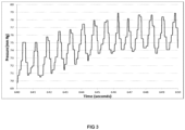
- Figure 3 provides more detailed analysis of the period during the balloon pump activation. It can be seen that there is a relatively consistent increase in pressure spikes achieved with each balloon expansion when the device is run on an 84 expansions per minute protocol. The increase in pressure with each expansion equates to about a 12.5% assistance to the ventricular contraction.
- the set-up of Figure 1 was altered by replacing the heart with a force measurement sensor.
- the force measurement sensor was modified with a custom manufactured plate installed to mimic the shape of the left ventricle.
- the operation of the device is able to apply a force on the plate in the same manner as it had to the heart, but in this case the precise force applied may be measured.
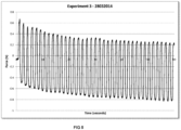
- Results of the balloon being operated under a protocol of about 37 expansions per minute are provided in Figure 5 . As can be seen from Figure 5 , approximately one newton force was consistently generated by the balloon during this test on each expansion. This is thought to be equivalent to about 20% of heart assistance at a rate sufficient to aid patient recovery.
- Figure 6 provides a schematic for the operation of a multi-balloon device according to the present invention.
- the device includes a left ventricular assist balloon (LVA balloon) separated from a multi chamber positioning balloon by a rigid support.
- the LVA balloon expansion cycles are controlled by a ECG gate system.
- This gate system includes a piezo driver that pushes gas in or draws gas away from the LVA balloon in order to power expansion and contraction of the balloon.
- the expansion and contraction of the LVA balloon can be co-ordinated to the beats of the heart in order to apply pressure to the left ventricle at the appropriate period of the cardiac cycle.
- the multi-chamber positioning balloon system may operate in isolation from the LVA balloon as expansion of the multi-chamber positioning balloon may be operated by a syringe via valve manifold.
- the multi-chamber positioning balloon may, for example, be inflated manually shortly after implantation to the patient in order to achieve expansion of the multi-chamber positioning balloon so as to fill the potential space between the pericardium and ventricular wall. Thereafter, the multi-chamber positioning balloon may be left inflated with only the inflation levels of the LVA balloon altered by the aforementioned drive system so as to apply the required cycles of pressure to the left ventricular wall.
- a double balloon device is illustrated in Figure 7 .
- a first balloon (1) is connected to a delivery hub (2) with a second balloon (3) also being connected to the delivery hub (2).
- the first and second balloons (1, 3) are provided on opposite sides of the delivery hub (2).
- the device is shown in deployed form.
- the second balloon (3) presents a first face as a broad substantially planar surface with a second substantially opposed face facing towards the first balloon (1).
- the substantially planar first face of the second balloon (3) would be placed against the pericardium.
- the first balloon (1) in expanded form expands to extend away from the second balloon (3) so as to form a convex profile.
- Expanding to form a convex profile forms a rounded bulge that in use applies pressure into the ventricular wall.
- Attached to the delivery hub (2) is a supply conduit (4).
- a tubing (not shown) for each of the balloons (1, 3) is transmitted through the supply conduit (4) to the delivery hub (2) and from there to each of the balloons (1, 3).
- a fluid gas or liquid may be transmitted back and forward independently along each of the tubing in order to inflate or deflate the balloons (1,3).
- Figure 8 illustrates one form of the present invention where a single balloon is employed.
- the illustration on the right-hand side of Figure 8 shows the device in a deployed format.
- This device includes fingers (5) that are arranged in a circle and splay in an arch outwardly from the centre of the circle.
- the fingers form a cupped cavity, from the centre of which the balloon (1) expands braced against the fingers.
- Elastic rings around the periphery of the circle formed by the fingers (5) urge the fingers (5) together and away from their natural splayed out position.
- the fingers (5) extend through a surgical opening in the pericardium and a splayed arrangement facing the ventricle forms a stop-projection that prevents the extraction of the device back through the pericardium, whilst at the same time providing a rigid or semi-rigid surface in association with the pericardium from which the balloon (1) may brace itself during expansion.
- the balloon is retained to the fingers (5) by rings.
- Expansion of the balloon (1) is achieved by air being pumped through the supply conduit (4).
- the pre-deployed format (or format ready for extraction) of the device is shown in the illustration on the left-hand side of Figure 8 .
- this format the balloon is collapsed and the fingers brought substantially together.
- the fingers are formed from a shaped memory wire which when heated by the action of an electrical cable conform to the shape on the left-hand side of the figure, but in the absence of heat via electrical cable the fingers conform to the shape shown on the right-hand side of Figure 8 .
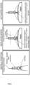
- Figure 9 shows a device in a configuration suitable for use during installation, in a configuration suitable for being deployed when in position and in a configuration when deployed and applying pressure to the ventricle (ie actuated state).
- This device does not include a balloon. Instead, the device includes an arm (6) that extends from the device after being urged by a solenoid or piezoelectric device. At the end of the arm is a substantially planar plate (7) which, in use, is forced against the surface of the ventricle by the extension of the arm (6) and thereby applies pressure to the ventricular tissue.
- the device includes a ring (8) that operates as a stop-projection from the device.
- the ring (8) In use, when the device is deployed within the pericardial space the ring (8) abuts with the pericardium, preventing the device from returning through the surgical induced hole in the pericardium used to implant the device, whilst also bracing the device between the pericardium and the extending arm (6).
- Figure 10 illustrates an alternative double-balloon device.
- the device in the deployed position, the device includes a first balloon (1) and a second balloon (2), when both balloons are expanded the first balloon (1) forms an annular ring defining a membrane (9) with the second balloon (2) expanding in the centre of the ring (1) and in the direction that is opposed to the membrane (9).
- the first balloon (1) of the device expands against the pericardium, whilst the second balloon (2) expands against the ventricular wall.
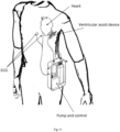
- Figure 11 shows the device of Figure 7 in place against the left ventricle and connected to a pump control system that is external to the body. Cutaneously applied ECG probes that feed back to the pump and control system are also shown.
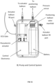
- Figure 12 provides further detail of the pump and control system.
Landscapes
- Health & Medical Sciences (AREA)
- Engineering & Computer Science (AREA)
- Heart & Thoracic Surgery (AREA)
- Cardiology (AREA)
- Hematology (AREA)
- Mechanical Engineering (AREA)
- Anesthesiology (AREA)
- Biomedical Technology (AREA)
- Life Sciences & Earth Sciences (AREA)
- Animal Behavior & Ethology (AREA)
- General Health & Medical Sciences (AREA)
- Public Health (AREA)
- Veterinary Medicine (AREA)
- Medical Informatics (AREA)
- Vascular Medicine (AREA)
- External Artificial Organs (AREA)
Applications Claiming Priority (3)
| Application Number | Priority Date | Filing Date | Title |
|---|---|---|---|
| GBGB1505624.5A GB201505624D0 (en) | 2015-04-01 | 2015-04-01 | Cardiac assist device |
| GBGB1505765.6A GB201505765D0 (en) | 2015-04-02 | 2015-04-02 | Cardiac assist device |
| PCT/GB2016/050925 WO2016156866A1 (en) | 2015-04-01 | 2016-04-01 | Cardiac assist device |
Publications (2)
| Publication Number | Publication Date |
|---|---|
| EP3277337A1 EP3277337A1 (en) | 2018-02-07 |
| EP3277337B1 true EP3277337B1 (en) | 2024-03-06 |
Family
ID=55697232
Family Applications (1)
| Application Number | Title | Priority Date | Filing Date |
|---|---|---|---|
| EP16715069.7A Active EP3277337B1 (en) | 2015-04-01 | 2016-04-01 | Cardiac assist device |
Country Status (8)
| Country | Link |
|---|---|
| US (1) | US10456514B2 (pl) |
| EP (1) | EP3277337B1 (pl) |
| JP (1) | JP6769618B2 (pl) |
| CN (1) | CN107810017B (pl) |
| AU (1) | AU2016240319B2 (pl) |
| ES (1) | ES2984380T3 (pl) |
| PL (1) | PL3277337T3 (pl) |
| WO (1) | WO2016156866A1 (pl) |
Families Citing this family (6)
| Publication number | Priority date | Publication date | Assignee | Title |
|---|---|---|---|---|
| JP7262099B2 (ja) * | 2018-12-26 | 2023-04-21 | 株式会社サンメディカル技術研究所 | 血液ポンプコントローラ及び補助人工心臓システム |
| WO2020152273A1 (de) | 2019-01-24 | 2020-07-30 | Artract Medical UG | Medizinisches kammersystem, einführsystem und kit |
| NL2022660B1 (en) | 2019-03-01 | 2020-09-15 | Stichting Katholieke Univ | Heart Assist Device |
| NL2028130B1 (en) | 2021-05-03 | 2022-11-10 | Cardiacbooster B V | Cardiac assist device with high frequency operation |
| CN115624691A (zh) * | 2022-09-26 | 2023-01-20 | 安徽通灵仿生科技有限公司 | 体外反搏的双闭环控制方法、系统及存储介质 |
| CN117504113B (zh) * | 2023-10-18 | 2024-05-17 | 吉林大学 | 压电间接驱动搏动型血泵 |
Citations (1)
| Publication number | Priority date | Publication date | Assignee | Title |
|---|---|---|---|---|
| WO2013082505A1 (en) * | 2011-12-01 | 2013-06-06 | The Trustees Of The University Of Pennsylvania | A non-blood contacting mechanical device that improves heart function after injury |
Family Cites Families (11)
| Publication number | Priority date | Publication date | Assignee | Title |
|---|---|---|---|---|
| US4771765A (en) | 1984-02-21 | 1988-09-20 | Choy Daniel S J | Heart assist device and method of use |
| ES2020787A6 (es) * | 1990-07-20 | 1991-09-16 | Figuera Aymerich Diego | Bomba intra-ventricular expansible de asistencia circulatoria. |
| AU1675995A (en) * | 1994-01-10 | 1995-08-01 | Cardassist Incorporated | Ventricular assist device |
| DE19538796C2 (de) | 1995-10-18 | 1999-09-23 | Fraunhofer Ges Forschung | Vorrichtung zur Unterstützung der Herzfunktion mit elastischen Füllkammern |
| AUPQ090499A0 (en) | 1999-06-10 | 1999-07-01 | Peters, William S | Heart assist device and system |
| AUPQ100699A0 (en) | 1999-06-17 | 1999-07-08 | Northern Sydney Area Health Service | An assist device for the failing heart |
| US6887192B1 (en) | 2000-09-08 | 2005-05-03 | Converge Medical, Inc. | Heart support to prevent ventricular remodeling |
| EP1594569B1 (en) | 2003-01-27 | 2014-05-14 | Corassist Cardiovascular Ltd. | In vivo device for improving diastolic ventricular function |
| US20070299296A1 (en) | 2006-06-22 | 2007-12-27 | Matthias Vaska | Devices and methods for absorbing, transferring, and delivering heart energy |
| US20080207986A1 (en) | 2007-02-26 | 2008-08-28 | Choy Daniel S J | Heart assist device |
| EP2229213A4 (en) | 2008-01-08 | 2012-10-17 | Univ Nat Cheng Kung | CARDIAC COMPRESSION SYSTEM |
-
2016
- 2016-04-01 WO PCT/GB2016/050925 patent/WO2016156866A1/en not_active Ceased
- 2016-04-01 CN CN201680030622.6A patent/CN107810017B/zh active Active
- 2016-04-01 EP EP16715069.7A patent/EP3277337B1/en active Active
- 2016-04-01 AU AU2016240319A patent/AU2016240319B2/en active Active
- 2016-04-01 PL PL16715069.7T patent/PL3277337T3/pl unknown
- 2016-04-01 JP JP2017550893A patent/JP6769618B2/ja active Active
- 2016-04-01 ES ES16715069T patent/ES2984380T3/es active Active
- 2016-04-01 US US15/563,299 patent/US10456514B2/en active Active
Patent Citations (1)
| Publication number | Priority date | Publication date | Assignee | Title |
|---|---|---|---|---|
| WO2013082505A1 (en) * | 2011-12-01 | 2013-06-06 | The Trustees Of The University Of Pennsylvania | A non-blood contacting mechanical device that improves heart function after injury |
Also Published As
| Publication number | Publication date |
|---|---|
| AU2016240319B2 (en) | 2020-03-19 |
| PL3277337T3 (pl) | 2024-07-15 |
| JP6769618B2 (ja) | 2020-10-14 |
| EP3277337A1 (en) | 2018-02-07 |
| JP2018513730A (ja) | 2018-05-31 |
| WO2016156866A1 (en) | 2016-10-06 |
| ES2984380T3 (es) | 2024-10-29 |
| US20180071444A1 (en) | 2018-03-15 |
| AU2016240319A1 (en) | 2017-10-19 |
| CN107810017B (zh) | 2022-06-21 |
| CN107810017A (zh) | 2018-03-16 |
| US10456514B2 (en) | 2019-10-29 |
Similar Documents
| Publication | Publication Date | Title |
|---|---|---|
| US10456514B2 (en) | Cardiac assist device | |
| US7118525B2 (en) | Implantable cardiac assist device | |
| US6918870B1 (en) | Assist device for the failing heart | |
| RU2703701C2 (ru) | Поддерживающее сердце устройство | |
| US6258021B1 (en) | Intrapericardial assist method | |
| EP2785393B1 (en) | A non-blood contacting mechanical device that improves heart function after injury | |
| CN113677298A (zh) | 心内左心房以及双支持系统 | |
| CN103282009B (zh) | 用于心肺复苏术的非侵入性装置 | |
| US20110196189A1 (en) | Extra-cardiac differential ventricular actuation by inertial and baric partitioning | |
| US20210379354A1 (en) | Ventricular assistance system and method | |
| JP2002532189A (ja) | 心臓の心室を補強する方法及び装置 | |
| EP3651826B1 (en) | Intracardiac pump | |
| US20070066862A1 (en) | Devices and methods for providing cardiac assistance | |
| US20140135567A1 (en) | Dual-Balloon Cardiac Pump | |
| US20120283507A1 (en) | Cardiac Assist Devices | |
| EP3845255B1 (en) | Cardiac pumping assistance device | |
| US20190209759A1 (en) | Ventricular assist devices | |
| AU742406B2 (en) | An assist device for the failing heart | |
| US20180104485A1 (en) | Dynamically controllable apparatus for assisting cardio-pulmonary resuscitation | |
| WO2022125651A1 (en) | Mechanical cardiac resynchronization therapy device | |
| Hord | Preclinical Efficacy of an Epicardial Heart Assist Device | |
| HK40065489A (en) | Intra-cardiac left atrial and dual support systems | |
| JPS6344385B2 (pl) |
Legal Events
| Date | Code | Title | Description |
|---|---|---|---|
| STAA | Information on the status of an ep patent application or granted ep patent |
Free format text: STATUS: THE INTERNATIONAL PUBLICATION HAS BEEN MADE |
|
| PUAI | Public reference made under article 153(3) epc to a published international application that has entered the european phase |
Free format text: ORIGINAL CODE: 0009012 |
|
| STAA | Information on the status of an ep patent application or granted ep patent |
Free format text: STATUS: REQUEST FOR EXAMINATION WAS MADE |
|
| 17P | Request for examination filed |
Effective date: 20170928 |
|
| AK | Designated contracting states |
Kind code of ref document: A1 Designated state(s): AL AT BE BG CH CY CZ DE DK EE ES FI FR GB GR HR HU IE IS IT LI LT LU LV MC MK MT NL NO PL PT RO RS SE SI SK SM TR |
|
| AX | Request for extension of the european patent |
Extension state: BA ME |
|
| DAV | Request for validation of the european patent (deleted) | ||
| DAX | Request for extension of the european patent (deleted) | ||
| STAA | Information on the status of an ep patent application or granted ep patent |
Free format text: STATUS: EXAMINATION IS IN PROGRESS |
|
| 17Q | First examination report despatched |
Effective date: 20200605 |
|
| REG | Reference to a national code |
Ref country code: DE Ref legal event code: R079 Ref document number: 602016086139 Country of ref document: DE Free format text: PREVIOUS MAIN CLASS: A61M0001100000 Ipc: A61M0060165000 Ref country code: DE Ref legal event code: R079 Free format text: PREVIOUS MAIN CLASS: A61M0001100000 Ipc: A61M0060165000 |
|
| P01 | Opt-out of the competence of the unified patent court (upc) registered |
Effective date: 20230523 |
|
| GRAP | Despatch of communication of intention to grant a patent |
Free format text: ORIGINAL CODE: EPIDOSNIGR1 |
|
| STAA | Information on the status of an ep patent application or granted ep patent |
Free format text: STATUS: GRANT OF PATENT IS INTENDED |
|
| RIC1 | Information provided on ipc code assigned before grant |
Ipc: A61M 60/268 20210101ALI20230608BHEP Ipc: A61M 60/531 20210101ALI20230608BHEP Ipc: A61M 60/554 20210101ALI20230608BHEP Ipc: A61M 60/165 20210101AFI20230608BHEP |
|
| INTG | Intention to grant announced |
Effective date: 20230705 |
|
| GRAJ | Information related to disapproval of communication of intention to grant by the applicant or resumption of examination proceedings by the epo deleted |
Free format text: ORIGINAL CODE: EPIDOSDIGR1 |
|
| STAA | Information on the status of an ep patent application or granted ep patent |
Free format text: STATUS: EXAMINATION IS IN PROGRESS |
|
| INTC | Intention to grant announced (deleted) | ||
| GRAP | Despatch of communication of intention to grant a patent |
Free format text: ORIGINAL CODE: EPIDOSNIGR1 |
|
| STAA | Information on the status of an ep patent application or granted ep patent |
Free format text: STATUS: GRANT OF PATENT IS INTENDED |
|
| INTG | Intention to grant announced |
Effective date: 20231012 |
|
| GRAS | Grant fee paid |
Free format text: ORIGINAL CODE: EPIDOSNIGR3 |
|
| GRAA | (expected) grant |
Free format text: ORIGINAL CODE: 0009210 |
|
| STAA | Information on the status of an ep patent application or granted ep patent |
Free format text: STATUS: THE PATENT HAS BEEN GRANTED |
|
| AK | Designated contracting states |
Kind code of ref document: B1 Designated state(s): AL AT BE BG CH CY CZ DE DK EE ES FI FR GB GR HR HU IE IS IT LI LT LU LV MC MK MT NL NO PL PT RO RS SE SI SK SM TR |
|
| REG | Reference to a national code |
Ref country code: GB Ref legal event code: FG4D |
|
| REG | Reference to a national code |
Ref country code: CH Ref legal event code: EP |
|
| REG | Reference to a national code |
Ref country code: DE Ref legal event code: R096 Ref document number: 602016086139 Country of ref document: DE |
|
| REG | Reference to a national code |
Ref country code: IE Ref legal event code: FG4D |
|
| REG | Reference to a national code |
Ref country code: LT Ref legal event code: MG9D |
|
| PG25 | Lapsed in a contracting state [announced via postgrant information from national office to epo] |
Ref country code: LT Free format text: LAPSE BECAUSE OF FAILURE TO SUBMIT A TRANSLATION OF THE DESCRIPTION OR TO PAY THE FEE WITHIN THE PRESCRIBED TIME-LIMIT Effective date: 20240306 |
|
| REG | Reference to a national code |
Ref country code: NL Ref legal event code: FP |
|
| PG25 | Lapsed in a contracting state [announced via postgrant information from national office to epo] |
Ref country code: RS Free format text: LAPSE BECAUSE OF FAILURE TO SUBMIT A TRANSLATION OF THE DESCRIPTION OR TO PAY THE FEE WITHIN THE PRESCRIBED TIME-LIMIT Effective date: 20240606 Ref country code: HR Free format text: LAPSE BECAUSE OF FAILURE TO SUBMIT A TRANSLATION OF THE DESCRIPTION OR TO PAY THE FEE WITHIN THE PRESCRIBED TIME-LIMIT Effective date: 20240306 |
|
| REG | Reference to a national code |
Ref country code: GR Ref legal event code: EP Ref document number: 20240401235 Country of ref document: GR Effective date: 20240716 |
|
| PG25 | Lapsed in a contracting state [announced via postgrant information from national office to epo] |
Ref country code: RS Free format text: LAPSE BECAUSE OF FAILURE TO SUBMIT A TRANSLATION OF THE DESCRIPTION OR TO PAY THE FEE WITHIN THE PRESCRIBED TIME-LIMIT Effective date: 20240606 Ref country code: NO Free format text: LAPSE BECAUSE OF FAILURE TO SUBMIT A TRANSLATION OF THE DESCRIPTION OR TO PAY THE FEE WITHIN THE PRESCRIBED TIME-LIMIT Effective date: 20240606 Ref country code: LT Free format text: LAPSE BECAUSE OF FAILURE TO SUBMIT A TRANSLATION OF THE DESCRIPTION OR TO PAY THE FEE WITHIN THE PRESCRIBED TIME-LIMIT Effective date: 20240306 Ref country code: HR Free format text: LAPSE BECAUSE OF FAILURE TO SUBMIT A TRANSLATION OF THE DESCRIPTION OR TO PAY THE FEE WITHIN THE PRESCRIBED TIME-LIMIT Effective date: 20240306 Ref country code: FI Free format text: LAPSE BECAUSE OF FAILURE TO SUBMIT A TRANSLATION OF THE DESCRIPTION OR TO PAY THE FEE WITHIN THE PRESCRIBED TIME-LIMIT Effective date: 20240306 Ref country code: BG Free format text: LAPSE BECAUSE OF FAILURE TO SUBMIT A TRANSLATION OF THE DESCRIPTION OR TO PAY THE FEE WITHIN THE PRESCRIBED TIME-LIMIT Effective date: 20240306 |
|
| PG25 | Lapsed in a contracting state [announced via postgrant information from national office to epo] |
Ref country code: SE Free format text: LAPSE BECAUSE OF FAILURE TO SUBMIT A TRANSLATION OF THE DESCRIPTION OR TO PAY THE FEE WITHIN THE PRESCRIBED TIME-LIMIT Effective date: 20240306 Ref country code: LV Free format text: LAPSE BECAUSE OF FAILURE TO SUBMIT A TRANSLATION OF THE DESCRIPTION OR TO PAY THE FEE WITHIN THE PRESCRIBED TIME-LIMIT Effective date: 20240306 |
|
| PG25 | Lapsed in a contracting state [announced via postgrant information from national office to epo] |
Ref country code: IS Free format text: LAPSE BECAUSE OF FAILURE TO SUBMIT A TRANSLATION OF THE DESCRIPTION OR TO PAY THE FEE WITHIN THE PRESCRIBED TIME-LIMIT Effective date: 20240706 |
|
| PG25 | Lapsed in a contracting state [announced via postgrant information from national office to epo] |
Ref country code: SM Free format text: LAPSE BECAUSE OF FAILURE TO SUBMIT A TRANSLATION OF THE DESCRIPTION OR TO PAY THE FEE WITHIN THE PRESCRIBED TIME-LIMIT Effective date: 20240306 Ref country code: PT Free format text: LAPSE BECAUSE OF FAILURE TO SUBMIT A TRANSLATION OF THE DESCRIPTION OR TO PAY THE FEE WITHIN THE PRESCRIBED TIME-LIMIT Effective date: 20240708 |
|
| PG25 | Lapsed in a contracting state [announced via postgrant information from national office to epo] |
Ref country code: EE Free format text: LAPSE BECAUSE OF FAILURE TO SUBMIT A TRANSLATION OF THE DESCRIPTION OR TO PAY THE FEE WITHIN THE PRESCRIBED TIME-LIMIT Effective date: 20240306 Ref country code: CZ Free format text: LAPSE BECAUSE OF FAILURE TO SUBMIT A TRANSLATION OF THE DESCRIPTION OR TO PAY THE FEE WITHIN THE PRESCRIBED TIME-LIMIT Effective date: 20240306 |
|
| PG25 | Lapsed in a contracting state [announced via postgrant information from national office to epo] |
Ref country code: SK Free format text: LAPSE BECAUSE OF FAILURE TO SUBMIT A TRANSLATION OF THE DESCRIPTION OR TO PAY THE FEE WITHIN THE PRESCRIBED TIME-LIMIT Effective date: 20240306 |
|
| REG | Reference to a national code |
Ref country code: ES Ref legal event code: FG2A Ref document number: 2984380 Country of ref document: ES Kind code of ref document: T3 Effective date: 20241029 |
|
| PG25 | Lapsed in a contracting state [announced via postgrant information from national office to epo] |
Ref country code: SM Free format text: LAPSE BECAUSE OF FAILURE TO SUBMIT A TRANSLATION OF THE DESCRIPTION OR TO PAY THE FEE WITHIN THE PRESCRIBED TIME-LIMIT Effective date: 20240306 Ref country code: SK Free format text: LAPSE BECAUSE OF FAILURE TO SUBMIT A TRANSLATION OF THE DESCRIPTION OR TO PAY THE FEE WITHIN THE PRESCRIBED TIME-LIMIT Effective date: 20240306 Ref country code: RO Free format text: LAPSE BECAUSE OF FAILURE TO SUBMIT A TRANSLATION OF THE DESCRIPTION OR TO PAY THE FEE WITHIN THE PRESCRIBED TIME-LIMIT Effective date: 20240306 Ref country code: PT Free format text: LAPSE BECAUSE OF FAILURE TO SUBMIT A TRANSLATION OF THE DESCRIPTION OR TO PAY THE FEE WITHIN THE PRESCRIBED TIME-LIMIT Effective date: 20240708 Ref country code: IS Free format text: LAPSE BECAUSE OF FAILURE TO SUBMIT A TRANSLATION OF THE DESCRIPTION OR TO PAY THE FEE WITHIN THE PRESCRIBED TIME-LIMIT Effective date: 20240706 Ref country code: EE Free format text: LAPSE BECAUSE OF FAILURE TO SUBMIT A TRANSLATION OF THE DESCRIPTION OR TO PAY THE FEE WITHIN THE PRESCRIBED TIME-LIMIT Effective date: 20240306 Ref country code: CZ Free format text: LAPSE BECAUSE OF FAILURE TO SUBMIT A TRANSLATION OF THE DESCRIPTION OR TO PAY THE FEE WITHIN THE PRESCRIBED TIME-LIMIT Effective date: 20240306 |
|
| REG | Reference to a national code |
Ref country code: DE Ref legal event code: R097 Ref document number: 602016086139 Country of ref document: DE |
|
| PG25 | Lapsed in a contracting state [announced via postgrant information from national office to epo] |
Ref country code: LU Free format text: LAPSE BECAUSE OF NON-PAYMENT OF DUE FEES Effective date: 20240401 |
|
| PG25 | Lapsed in a contracting state [announced via postgrant information from national office to epo] |
Ref country code: LU Free format text: LAPSE BECAUSE OF NON-PAYMENT OF DUE FEES Effective date: 20240401 |
|
| PG25 | Lapsed in a contracting state [announced via postgrant information from national office to epo] |
Ref country code: MC Free format text: LAPSE BECAUSE OF FAILURE TO SUBMIT A TRANSLATION OF THE DESCRIPTION OR TO PAY THE FEE WITHIN THE PRESCRIBED TIME-LIMIT Effective date: 20240306 |
|
| PLBE | No opposition filed within time limit |
Free format text: ORIGINAL CODE: 0009261 |
|
| STAA | Information on the status of an ep patent application or granted ep patent |
Free format text: STATUS: NO OPPOSITION FILED WITHIN TIME LIMIT |
|
| PG25 | Lapsed in a contracting state [announced via postgrant information from national office to epo] |
Ref country code: DK Free format text: LAPSE BECAUSE OF FAILURE TO SUBMIT A TRANSLATION OF THE DESCRIPTION OR TO PAY THE FEE WITHIN THE PRESCRIBED TIME-LIMIT Effective date: 20240306 |
|
| PG25 | Lapsed in a contracting state [announced via postgrant information from national office to epo] |
Ref country code: MC Free format text: LAPSE BECAUSE OF FAILURE TO SUBMIT A TRANSLATION OF THE DESCRIPTION OR TO PAY THE FEE WITHIN THE PRESCRIBED TIME-LIMIT Effective date: 20240306 Ref country code: DK Free format text: LAPSE BECAUSE OF FAILURE TO SUBMIT A TRANSLATION OF THE DESCRIPTION OR TO PAY THE FEE WITHIN THE PRESCRIBED TIME-LIMIT Effective date: 20240306 |
|
| 26N | No opposition filed |
Effective date: 20241209 |
|
| PG25 | Lapsed in a contracting state [announced via postgrant information from national office to epo] |
Ref country code: SI Free format text: LAPSE BECAUSE OF FAILURE TO SUBMIT A TRANSLATION OF THE DESCRIPTION OR TO PAY THE FEE WITHIN THE PRESCRIBED TIME-LIMIT Effective date: 20240306 |
|
| PGFP | Annual fee paid to national office [announced via postgrant information from national office to epo] |
Ref country code: NL Payment date: 20250429 Year of fee payment: 10 |
|
| PGFP | Annual fee paid to national office [announced via postgrant information from national office to epo] |
Ref country code: DE Payment date: 20250430 Year of fee payment: 10 |
|
| PGFP | Annual fee paid to national office [announced via postgrant information from national office to epo] |
Ref country code: ES Payment date: 20250514 Year of fee payment: 10 |
|
| PGFP | Annual fee paid to national office [announced via postgrant information from national office to epo] |
Ref country code: IT Payment date: 20250429 Year of fee payment: 10 Ref country code: BE Payment date: 20250429 Year of fee payment: 10 |
|
| REG | Reference to a national code |
Ref country code: AT Ref legal event code: UEP Ref document number: 1662888 Country of ref document: AT Kind code of ref document: T Effective date: 20240306 |
|
| PGFP | Annual fee paid to national office [announced via postgrant information from national office to epo] |
Ref country code: FR Payment date: 20250429 Year of fee payment: 10 |
|
| PGFP | Annual fee paid to national office [announced via postgrant information from national office to epo] |
Ref country code: GR Payment date: 20250428 Year of fee payment: 10 |
|
| PGFP | Annual fee paid to national office [announced via postgrant information from national office to epo] |
Ref country code: CH Payment date: 20250501 Year of fee payment: 10 |
|
| PGFP | Annual fee paid to national office [announced via postgrant information from national office to epo] |
Ref country code: AT Payment date: 20250502 Year of fee payment: 10 |
|
| PGFP | Annual fee paid to national office [announced via postgrant information from national office to epo] |
Ref country code: IE Payment date: 20250429 Year of fee payment: 10 |
|
| PG25 | Lapsed in a contracting state [announced via postgrant information from national office to epo] |
Ref country code: CY Free format text: LAPSE BECAUSE OF FAILURE TO SUBMIT A TRANSLATION OF THE DESCRIPTION OR TO PAY THE FEE WITHIN THE PRESCRIBED TIME-LIMIT; INVALID AB INITIO Effective date: 20160401 |
|
| PG25 | Lapsed in a contracting state [announced via postgrant information from national office to epo] |
Ref country code: HU Free format text: LAPSE BECAUSE OF FAILURE TO SUBMIT A TRANSLATION OF THE DESCRIPTION OR TO PAY THE FEE WITHIN THE PRESCRIBED TIME-LIMIT; INVALID AB INITIO Effective date: 20160401 |
|
| PG25 | Lapsed in a contracting state [announced via postgrant information from national office to epo] |
Ref country code: TR Free format text: LAPSE BECAUSE OF FAILURE TO SUBMIT A TRANSLATION OF THE DESCRIPTION OR TO PAY THE FEE WITHIN THE PRESCRIBED TIME-LIMIT Effective date: 20240306 |
|
| PGFP | Annual fee paid to national office [announced via postgrant information from national office to epo] |
Ref country code: GB Payment date: 20260331 Year of fee payment: 11 |
|
| PGFP | Annual fee paid to national office [announced via postgrant information from national office to epo] |
Ref country code: PL Payment date: 20260323 Year of fee payment: 11 |
|
| REG | Reference to a national code |
Ref country code: CH Ref legal event code: U11 Free format text: ST27 STATUS EVENT CODE: U-0-0-U10-U11 (AS PROVIDED BY THE NATIONAL OFFICE) Effective date: 20260501 |