EP3277326B1 - Sterilizing method and apparatus - Google Patents
Sterilizing method and apparatus Download PDFInfo
- Publication number
- EP3277326B1 EP3277326B1 EP16774196.6A EP16774196A EP3277326B1 EP 3277326 B1 EP3277326 B1 EP 3277326B1 EP 16774196 A EP16774196 A EP 16774196A EP 3277326 B1 EP3277326 B1 EP 3277326B1
- Authority
- EP
- European Patent Office
- Prior art keywords
- filter
- sterilizing cabinet
- sterilizing
- cabinet
- door
- Prior art date
- Legal status (The legal status is an assumption and is not a legal conclusion. Google has not performed a legal analysis and makes no representation as to the accuracy of the status listed.)
- Active
Links
- 230000001954 sterilising effect Effects 0.000 title claims description 505
- 238000000034 method Methods 0.000 title claims description 35
- 238000004659 sterilization and disinfection Methods 0.000 claims description 91
- 210000001364 upper extremity Anatomy 0.000 claims description 15
- 239000000463 material Substances 0.000 description 58
- 125000006850 spacer group Chemical group 0.000 description 41
- 239000000853 adhesive Substances 0.000 description 28
- 230000001070 adhesive effect Effects 0.000 description 28
- 239000003206 sterilizing agent Substances 0.000 description 20
- 230000008569 process Effects 0.000 description 17
- 239000000126 substance Substances 0.000 description 13
- 239000001913 cellulose Substances 0.000 description 11
- 229920002678 cellulose Polymers 0.000 description 11
- 239000000123 paper Substances 0.000 description 10
- 239000012530 fluid Substances 0.000 description 9
- 239000012528 membrane Substances 0.000 description 9
- 239000004743 Polypropylene Substances 0.000 description 7
- 230000007246 mechanism Effects 0.000 description 7
- -1 polypropylene Polymers 0.000 description 7
- 229920001155 polypropylene Polymers 0.000 description 7
- 229920000642 polymer Polymers 0.000 description 4
- 229920001296 polysiloxane Polymers 0.000 description 4
- XLYOFNOQVPJJNP-UHFFFAOYSA-N water Substances O XLYOFNOQVPJJNP-UHFFFAOYSA-N 0.000 description 4
- 239000003795 chemical substances by application Substances 0.000 description 3
- 239000007789 gas Substances 0.000 description 3
- 238000003780 insertion Methods 0.000 description 3
- 230000037431 insertion Effects 0.000 description 3
- 238000007689 inspection Methods 0.000 description 3
- 239000002184 metal Substances 0.000 description 3
- 239000011148 porous material Substances 0.000 description 3
- 230000000717 retained effect Effects 0.000 description 3
- 238000007789 sealing Methods 0.000 description 3
- 238000000926 separation method Methods 0.000 description 3
- 229910000838 Al alloy Inorganic materials 0.000 description 2
- 230000004888 barrier function Effects 0.000 description 2
- 239000003086 colorant Substances 0.000 description 2
- 150000001875 compounds Chemical class 0.000 description 2
- 238000009833 condensation Methods 0.000 description 2
- 230000005494 condensation Effects 0.000 description 2
- 238000010276 construction Methods 0.000 description 2
- 230000003247 decreasing effect Effects 0.000 description 2
- 229940079593 drug Drugs 0.000 description 2
- 239000003814 drug Substances 0.000 description 2
- 239000004744 fabric Substances 0.000 description 2
- 238000001914 filtration Methods 0.000 description 2
- 230000036512 infertility Effects 0.000 description 2
- 239000007788 liquid Substances 0.000 description 2
- 229910052751 metal Inorganic materials 0.000 description 2
- 229910001092 metal group alloy Inorganic materials 0.000 description 2
- 238000012986 modification Methods 0.000 description 2
- 230000004048 modification Effects 0.000 description 2
- 229920006395 saturated elastomer Polymers 0.000 description 2
- 229920001169 thermoplastic Polymers 0.000 description 2
- 230000009466 transformation Effects 0.000 description 2
- 241000894006 Bacteria Species 0.000 description 1
- 241000233866 Fungi Species 0.000 description 1
- XUIMIQQOPSSXEZ-UHFFFAOYSA-N Silicon Chemical compound [Si] XUIMIQQOPSSXEZ-UHFFFAOYSA-N 0.000 description 1
- 241000700605 Viruses Species 0.000 description 1
- 230000003466 anti-cipated effect Effects 0.000 description 1
- 238000005452 bending Methods 0.000 description 1
- 230000015572 biosynthetic process Effects 0.000 description 1
- 230000008859 change Effects 0.000 description 1
- 239000002131 composite material Substances 0.000 description 1
- 230000001010 compromised effect Effects 0.000 description 1
- 230000006378 damage Effects 0.000 description 1
- 230000001066 destructive effect Effects 0.000 description 1
- 238000006073 displacement reaction Methods 0.000 description 1
- 230000008030 elimination Effects 0.000 description 1
- 238000003379 elimination reaction Methods 0.000 description 1
- 239000001963 growth medium Substances 0.000 description 1
- 238000010438 heat treatment Methods 0.000 description 1
- 208000015181 infectious disease Diseases 0.000 description 1
- 230000002458 infectious effect Effects 0.000 description 1
- 230000002452 interceptive effect Effects 0.000 description 1
- 238000002483 medication Methods 0.000 description 1
- 150000002739 metals Chemical class 0.000 description 1
- 230000000813 microbial effect Effects 0.000 description 1
- 239000001301 oxygen Substances 0.000 description 1
- 229910052760 oxygen Inorganic materials 0.000 description 1
- 239000002245 particle Substances 0.000 description 1
- 230000000149 penetrating effect Effects 0.000 description 1
- 239000004033 plastic Substances 0.000 description 1
- 230000003014 reinforcing effect Effects 0.000 description 1
- 229910052710 silicon Inorganic materials 0.000 description 1
- 239000010703 silicon Substances 0.000 description 1
- 239000002210 silicon-based material Substances 0.000 description 1
- 230000003068 static effect Effects 0.000 description 1
- 238000012360 testing method Methods 0.000 description 1
- 229920002725 thermoplastic elastomer Polymers 0.000 description 1
- 239000004416 thermosoftening plastic Substances 0.000 description 1
- 238000013022 venting Methods 0.000 description 1
- 238000011179 visual inspection Methods 0.000 description 1
- 239000001993 wax Substances 0.000 description 1
Images


Classifications
-
- A—HUMAN NECESSITIES
- A61—MEDICAL OR VETERINARY SCIENCE; HYGIENE
- A61L—METHODS OR APPARATUS FOR STERILISING MATERIALS OR OBJECTS IN GENERAL; DISINFECTION, STERILISATION OR DEODORISATION OF AIR; CHEMICAL ASPECTS OF BANDAGES, DRESSINGS, ABSORBENT PADS OR SURGICAL ARTICLES; MATERIALS FOR BANDAGES, DRESSINGS, ABSORBENT PADS OR SURGICAL ARTICLES
- A61L2/00—Methods or apparatus for disinfecting or sterilising materials or objects other than foodstuffs or contact lenses; Accessories therefor
- A61L2/02—Methods or apparatus for disinfecting or sterilising materials or objects other than foodstuffs or contact lenses; Accessories therefor using physical phenomena
- A61L2/04—Heat
- A61L2/06—Hot gas
- A61L2/07—Steam
-
- A—HUMAN NECESSITIES
- A61—MEDICAL OR VETERINARY SCIENCE; HYGIENE
- A61L—METHODS OR APPARATUS FOR STERILISING MATERIALS OR OBJECTS IN GENERAL; DISINFECTION, STERILISATION OR DEODORISATION OF AIR; CHEMICAL ASPECTS OF BANDAGES, DRESSINGS, ABSORBENT PADS OR SURGICAL ARTICLES; MATERIALS FOR BANDAGES, DRESSINGS, ABSORBENT PADS OR SURGICAL ARTICLES
- A61L2/00—Methods or apparatus for disinfecting or sterilising materials or objects other than foodstuffs or contact lenses; Accessories therefor
- A61L2/26—Accessories or devices or components used for biocidal treatment
-
- A—HUMAN NECESSITIES
- A61—MEDICAL OR VETERINARY SCIENCE; HYGIENE
- A61L—METHODS OR APPARATUS FOR STERILISING MATERIALS OR OBJECTS IN GENERAL; DISINFECTION, STERILISATION OR DEODORISATION OF AIR; CHEMICAL ASPECTS OF BANDAGES, DRESSINGS, ABSORBENT PADS OR SURGICAL ARTICLES; MATERIALS FOR BANDAGES, DRESSINGS, ABSORBENT PADS OR SURGICAL ARTICLES
- A61L2202/00—Aspects relating to methods or apparatus for disinfecting or sterilising materials or objects
- A61L2202/10—Apparatus features
- A61L2202/12—Apparatus for isolating biocidal substances from the environment
- A61L2202/122—Chambers for sterilisation
-
- A—HUMAN NECESSITIES
- A61—MEDICAL OR VETERINARY SCIENCE; HYGIENE
- A61L—METHODS OR APPARATUS FOR STERILISING MATERIALS OR OBJECTS IN GENERAL; DISINFECTION, STERILISATION OR DEODORISATION OF AIR; CHEMICAL ASPECTS OF BANDAGES, DRESSINGS, ABSORBENT PADS OR SURGICAL ARTICLES; MATERIALS FOR BANDAGES, DRESSINGS, ABSORBENT PADS OR SURGICAL ARTICLES
- A61L2202/00—Aspects relating to methods or apparatus for disinfecting or sterilising materials or objects
- A61L2202/20—Targets to be treated
- A61L2202/24—Medical instruments, e.g. endoscopes, catheters, sharps
Definitions
- Exemplary embodiments of the present invention relate to a method and apparatus for sterilization and more particularly to a method and apparatus for sterilization of instruments.
- Sterilization is a term referring to any process that eliminates (removes) or kills microbial life, including transmissible agents (such as fungi, bacteria, viruses, or spore forms) present on a surface, or contained in a fluid, or in medication, or in a compound such as biological culture media. Sterilization can be achieved by applying heat, chemicals, irradiation, high pressure, and filtration or combinations thereof.
- surgical instruments and medications that enter an already aseptic part of the body must be sterilized to a high sterility assurance level.
- examples of such instruments include scalpels, hypodermic needles and implantable medical devices (IMD), such as artificial pacemakers.
- IMD implantable medical devices
- a widely used method for heat sterilization is the autoclave, sometimes referred to as a converter.
- Autoclaves commonly use steam heated to 121-134 °C.
- a holding time of at least 15 minutes at 121 °C at 100 kPa, or 3 minutes at 134 °C at 100 kPa is required.
- Additional sterilizing time is usually required for liquids and instruments packed in layers of cloth, as they may take longer to reach the required temperature.
- One method of sterilization involves passing steam through a cabinet.
- steam needs to penetrate the cabinet load uniformly. Accordingly, the cabinet must not be overcrowded, and the lids of bottles and containers must be left ajar. During the initial heating of the chamber, residual air must be removed. Indicators should be placed in the most difficult places for the steam to reach to ensure that steam actually penetrates there.
- a filter is typically placed over the vent to keep particles or extraneous materials from entering the cabinet before, during or after the sterilizing process. Once the sterilizing process is completed the filter needs to be removed and inspected by medical professionals to verify the integrity of the sterilizing process was maintained. If it is discovered during inspection that the filter did not remain intact, the sterilizing process has to be repeated with a new filter.
- US 8 454 901 B1 discloses a mobile apparatus and method to sterilize surgical trays.
- a cabinet has filtered cabinet roof vents, filtered cabinet floor vents, doors sealably covering a cabinet front aperture, shelves sized to support surgical trays, and wheels.
- Surgical trays are placed within the cabinet, the cabinet doors are closed, and the mobile apparatus is placed within an autoclave and sterilized.
- the cabinet doors are not unsealed until the cabinet is in the operating room, ready for use.
- doors are opened, trays removed, and their contents used.
- Wheels on the cabinet facilitate moving the cabinet from autoclave to storage or operating room. Method steps include periodically replacing the filters and door gasket.
- US 2014/0348722 A1 discloses a surgical sterilizing container, which consists of a container tub having a bottom, an outer wall protruding from the bottom, and a lid.
- the bottom includes a fluid drainage surface such that fluid, in particular, condensate formed during the sterilization process, is drained off from the fluid drainage surface into depressions located at the transverse side wall. Fluid is lifted out of the fluid collection area by a fluid lifting device and conducted to an outlet valve to remove fluid from the container interior.
- the sterilization container includes a tray that can store materials to be cleaned and sterilized such as an endoscope.
- the tray may include a lid that is separated or a lid that is integral to the tray.
- the tray may be placed in an endoscope treatment chamber and a machine chamber.
- a first treatment section the endoscope in the tray is cleaned or cleaned and disinfected.
- a second treatment section the endoscope in the tray is sterilized.
- the tray is detachably connected to a tray connecting portion and a discharge port is detachably connected to a solution discharge valve of the tray.
- JP 2009 285 009 A discloses a sterilizer for sterilizing articles to be treated under low-oxygen conditions at normal pressure with saturated steam.
- the sterilizer comprises a treatment chamber for housing the articles to be treated; a steam feeding part for feeding saturated steam to the inside of the treatment chamber; a water collecting part provided by denting the bottom surface of the treatment chamber for collecting dew condensation water generated in the treatment chamber; and a means for removing dew condensation water collected in the water collecting part.
- US 4 728 504 A discloses a medical instruments sterilization container, which includes a housing and a removable dome-shaped lid having a filtered inlet port disposed therethrough for permitting the passage of gas or steam into housing.
- a removable tray is adapted to be disposed within housing to hold various instruments to be sterilized and includes apertures formed on the bottom of the tray for permitting condensate to drain therefrom.
- the bottom surface of housing is sloped to two locations centred on opposite sides thereof and includes filtered outlet ports positioned at the two locations to permit discharged air and condensate to exit housing.
- a sterilizing cabinet assembly according to the invention is defined by claim 1.
- a method of sterilizing using the sterilizing cabinet assembly according to the invention is defined by claims 5 and 7.
- Preferred embodiments of the invention are defined by claims 2 to 4, 6, and 8.
- the invention provides a sterilizing cabinet assembly, including a cabinet having an access port and a bottom; a door connected to the cabinet, the door moveable between an open position permitting passage through the access port to an interior of the cabinet and a closed position precluding passage through the access port; the door having a vent port, wherein the bottom induces condensate on the bottom to flow to the vent port; and a filter overlying the vent port and forming a sealed interface with an adjacent portion of the door.
- the invention further provides a method of sterilizing, which includes occluding a vent port of the sterilizing cabinet with a filter, the sterilizing cabinet having an internal inclined surface to induce a condensate flow to the vent port; performing a sterilization cycle on the sterilizing cabinet; and draining at least a portion of a condensate formed in the sterilization cycle along the inclined surface to pass from the sterilizing cabinet through the filter.
- Another method according to the invention includes locating a sterilizing cabinet in an autoclave; applying a sterilization cycle to the sterilizing cabinet in the autoclave; and draining along an inclined surface in the sterilizing cabinet at least a portion of a condensate from the sterilizing cabinet during the sterilization cycle.
- FIG. 1a is a front view of sterilizing cabinet 100. It should be noted that embodiments of the present invention are not limited to the particular configuration of sterilizing cabinet 100.
- sterilizing cabinet 100 encompasses any device capable of sterilizing.
- the term also includes sterilizing cabinets for sterilizing medical instruments, surgical devices and the like.
- Sterilizing cabinet 100 includes door or doors 102, vents 104, filter holder 106, primary filter 108, secondary filter 110, sterilizing cabinet frame 112 and legs 114.
- Door or doors 102 are able to open and close for access to the interior of sterilizing cabinet 100.
- Door or doors 102 are physically connected to sterilizing cabinet frame 112.
- Door or doors 102 can be attached through the use of a hinge or hinges which allows the doors to swing open.
- door or doors 102 can be removable from sterilizing cabinet 100 through the use of clamps (not shown in Figure 1 ). It should be appreciated that exemplary embodiments of door or doors 102 include any mechanism that allows for door or doors 102 to move from an open position to a closed position to provide access to the interior of sterilizing cabinet 100.
- Sterilizing cabinet 100 in this embodiment provides for four vents 104.
- exemplary embodiments of sterilizing cabinet 100 are not limited to four vents.
- Exemplary embodiments of sterilizing cabinet 100 can include one or more vents.
- Vents 104 provide numerous small openings for the passage of sterilizing steam.
- the small openings in vents 104 can be holes or slits.
- vents 104 can be fenestrated.
- Primary filter 108 in conjunction with filter holder 106 covers vent 104.
- Primary filter 108 with filter holder 106 forms a seal with the adjacent portions of sterilizing cabinet 100 such that during the operation of a sterilizing cycle, any sterilizing steam that passes through the vent 104 must then pass through primary filter 108.
- Primary filter 108 can be made of a very thin paper. Exemplary embodiments provide that primary filter 108 can be made of any porous material that (1) allows for the passage of sterilizing steam from sterilizing cabinet 100 and (2) prevents extraneous materials from passing through primary filter 108 and entering vent 104.
- Primary filter 108 is removable from sterilizing cabinet 100 and is typically replaced with a new filter following each sterilizing cycle.
- Secondary filter 110 resides on top of primary filter 108 in filter holder 106. Secondary filter 110 covers primary filter 108 and forms a seal with primary filter 108 through filter holder 106 such that any sterilizing steam that passes through the vent 104 must then pass through primary filter 108 and secondary filter 110. Secondary filter 110 can be made of a very thin paper. Secondary filter 110 can be made of any porous material that (1) allows for the passage of sterilizing steam from sterilizing cabinet 100 and primary filter 108 and (2) prevents extraneous materials from passing through secondary filter 108.
- Exemplary embodiments of this disclosure provide for secondary filter 110 to form a sealed periphery with primary filter 108.
- the sealed interface between the primary filter 108 and the adjacent portion of either the sterilizing cabinet 100 is independent of an interface between secondary filter 110 and primary filter 108.
- One exemplary arrangement provides for primary filter 108 and secondary filter 110 to be coextensive.
- primary filter 108 and secondary filter 110 have different filter properties. For instance, primary filter 108 and secondary filter 110 may filter different elements of the sterilizing agent which exits sterilizing cabinet 100 during a sterilization cycle.
- primary filter 108 and secondary filter 110 have similar filter properties.
- Another exemplary embodiment provides that primary filter 108 and secondary filter 110 are different colors.
- primary filter 108 may be the only filter that covers vent 104.
- primary filter 108 is removeably held or maintained in place over vent 104 by filter holder 106.
- Primary filter 108 forms a seal with the adjacent portions of sterilizing cabinet 100 such that during the operation of a sterilizing cycle, any sterilizing steam that passes through the vent 104 must then pass through primary filter 108.
- primary filter 108 can be made of any porous material that (1) allows for the passage of sterilizing steam from sterilizing cabinet 100 and (2) prevents extraneous materials from passing through primary filter 108 and entering vent 104.
- Primary filter 108 is removable from sterilizing cabinet 100 and is typically replaced with a new filter following each sterilizing cycle.
- Legs 114 reside on the bottom of sterilizing cabinet 100 and provide spacing between the surface which sterilizing cabinet 100 rests and the bottom primary filter 108, secondary filter 110 and filter holder 106.
- Figure 1b provides a top view of sterilizing cabinet 100 showing vent 104 covered by filter holder 106, primary filter 108, secondary filter 110, sterilizing cabinet frame 112 and hinge 116 of filter holder 106.
- Hinge 116 with filter holder 106 allows a portion of filter holder 106 to swing open about hinge 116 such that primary filter 108 and secondary filter 110 can be removed independent of one another.
- filter holder 106 allows for secondary filter 110 to be released and removed from filter holder 106 while simultaneously maintaining primary filter's 108 seal with sterilizing cabinet 100 over vent 104.
- Figure 1c shows a side view of sterilizing cabinet 100 including sterilizing cabinet frame 112, vent 104, primary filter 108, secondary filter 110, filter holder 106 and hinge 116.
- sterilizing cabinet 100 may include a steam exposure indicator on either the primary filter 108 or the secondary filter 110 which designates when steam from sterilizing cabinet 100 has passed through one of the filters.
- An example of one such steam exposure indicator is a tape that changes colors when exposed to steam.
- Figure 2a provides a perspective view of sterilizing cabinet 100 with two vents 104 on the top and two vents 104 on the bottom of sterilizing cabinet 100.
- Figure 2a also includes primary filters 108 occluding vents 104 and secondary filters 110 overlaying primary filters 108 with primary filters 108 and secondary filters 110 each in filter holders 106.
- Figure 2b provides a top view of sterilizing cabinet 100 with an alternative exemplary embodiment of filter holder 106. Shown in Figure 2b are two vents 104 occluded by primary filters 108 which are also covered by secondary filters 110.
- filter holders 106 do not have a swinging hinge which allows for the individual attachment and release of primary filters 108 and secondary filters 110.
- filter holders 106 allow for independently removing primary filter 108 and secondary filter 110 through the use of a sliding mechanism. Secondary filter 110 can be removed by sliding it out of filter holder 106 while maintaining primary filter's 108 seal with sterilizing cabinet 100 around vent 104.
- filter holder 106 again does not include a swinging hinge, but allows for the placement and removal of only primary filter 108 by a sliding mechanism.
- Only primary filter 108 in conjunction with filter holder 106 forms a sealed interface with sterilizing cabinet 100 occluding vents 104. Primary filter 108 can then be placed or removed by sliding into and out of filter holder 106.
- an exemplary embodiment of a process of placing primary filter 108 and secondary filter 110 includes disposing primary filter 108 to occlude a vent 104 of sterilizing cabinet 100 and forming a first sealed interface with the sterilizing cabinet 100. The process continues by forming a second sealed interface between secondary filter 110 (or confirmatory filter) and at least a portion of one of sterilizing cabinet 100 and primary filter 108, a portion of the secondary filter 110 overlying a portion of the primary filter 108. The process can continue by passing a sterilizing agent (typically steam) through primary filter 108 and secondary filter 110 and vent 104.
- a sterilizing agent typically steam
- an exemplary embodiment of a process of placing only a primary filter 108 includes disposing primary filter 108 with filter holder 106 to occlude vent 104 of sterilizing cabinet 100 creating a sealed interface with the sterilizing cabinet 100.
- the process can continue by passing a sterilizing agent (typically steam) through primary filter 108 and vent 104.
- the process can then conclude with verifying the integrity of primary filter 108 by either inspecting primary filter 108 while it covers vent 104 in filter holder 106 or after it is removed from filter holder 106.
- the process may be repeated if it is determined that the integrity of primary filter 108 was compromised during the sterilizing process.
- Exemplary embodiments of inspecting primary filter 108 and/or secondary filter 110 can include visual inspection by either medical or non-medical personnel, inspecting by an electronic device or machine, or inspecting through mechanical means.
- Exemplary embodiments of inspecting by an electronic device or machine includes any type of device that is able to scan or image the primary filter 108 and/or secondary filter 110 such that the scanned or imaged picture of the primary filter 108 and/or secondary filter 110 can be digitally viewed or examined for imperfections such as rips or cuts that would impact the integrity of the sterilization cycle.
- Exemplary embodiments of mechanical inspection includes any type of inspection means that physically test that the integrity of the primary filter 108 and/or secondary filter 110 has been maintained.
- exemplary embodiments of a sterilizing agent include any substance that provides for the destruction or elimination of living organisms, which often include heat, steam, pressure, gas, plasma, irradiation, chemical compounds, and chemical vapor.
- Exemplary embodiments of this process provide that the first sealed interface is separate from the second sealed interface. Additionally, failure of the second sealed interface is independent of the first sealed interface. For example, if the second sealed interface fails and leaks sterilizing steam during a sterilization cycle, the first sealed interface should remain intact and should not be affected by the failure of the second sealed interface.
- FIG. 3a a top view of an exemplary vent 104 is shown.
- a fenestrated surface with numerous openings that allow for the passage of a sterilizing agent, such as steam from sterilizing cabinet 100 during a sterilization cycle.
- a sterilizing agent such as steam from sterilizing cabinet 100 during a sterilization cycle.
- Figure 3a merely represents one embodiment of vent 104 and that exemplary embodiments of vent 104 include any arrangement of holes or openings that allow for the passage of a sterilizing agent.
- Figure 3b provides a top view of a filtering arrangement covering vent 104. Shown in Figure 3b is the top portion of secondary filter 110, filter holder 106 with hinges 116 and pin 118. Exemplary embodiments of this arrangement provide for a silicon seal between filter holder 106 and primary filter 108, between filter holder 106 and secondary filter 110 and sterilizing cabinet 100. This seal serves two primary purposes. First, it forces all of the sterilizing agent that enters and exits the sterilizing cabinet 100 to pass through the filters. Second, it keeps extraneous materials from entering the sterilizing cabinet 100 through vents 104, which are covered by primary filter 108 and secondary filter 110.
- exemplary embodiments of the sealed interface between the primary filter 108 and the sterilizing cabinet 100 includes both direct contact between primary filter 108 and sterilizing cabinet 100 as well as indirect contact between primary filter 108 and sterilizing cabinet 100 through the use of a sealing agent, such as caulk or an adhesive.
- a sealing agent such as caulk or an adhesive.
- the sealed interface between the secondary filter and the primary filter 108 or filter holder 106 includes both direct contact between primary filter 108 or filter holder 106 as well as indirect contact through the use of a sealing agent, such as caulk or an adhesive.
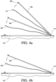
- FIG. 4a provided is a side view of the different elements and the type of movement allowed for filter holder 106. Shown in Figure 4a is the outside face of sterilizing cabinet 100, vent 104, primary filter 108, secondary filter 110, hinge 116, filter holder 106 section 402 which secures primary filter 108, and filter holder 106 section 404 which secures secondary filter 110.
- sections 402 and 404 are able to rotate about hinge 116 and can be moved from the closed position (covering vent 104) to the open position (not covering vent 104) independent of each other. For instance section 404 can be moved to the open position while section 402 remains in the closed position.
- section 404 in order for section 402 to move to the open position, section 404 must also be in the open position since it overlays section 402. Also shown in Figure 4a are holes 406 on section 402, section 404 and on sterilizing cabinet 100. When section 402 and 404 are in the closed position, the holes 406 line-up such that a pin 118 or locking key can be inserted through the holes 406. This prevents sections 402 and 404 from opening during a sterilization cycle or at any other time when opening would be undesirable.
- sections 402 and 404 are maintained or locked in the closed position through the use of a clamp or latch. It can be appreciated that exemplary embodiments of these teachings provide for any mechanism that allows sections 402 and 404 of filter holder 106 to be maintained securely in the closed position and then opened when desired.
- Figure 4b provides a perspective view of the movement of an alternative filter arrangement of a sterilizing cabinet. Shown in Figure 4b is the outside face of sterilizing cabinet 100, vent 104, primary filter 108, hinge 116, and filter holder 106 section 402, which secures primary filter 108. It should be noted that in this exemplary embodiment, there is only one filter (i.e., primary filter 108) and one filter holder 106 section 402. Here, filter holder 106 section 402 is able to rotate about hinge 116. It can be moved from the closed position (covering vent 104) to the open position (not covering vent 104). Also shown in Figure 4b are holes 406 on section 402. When section 402 is in the closed position, the holes 406 line-up such that a pin 118 or locking key can be inserted through the holes 406. This prevents section 402 from opening during a sterilization cycle or at any other time when opening would be undesirable.
- section 402 is maintained or locked in the closed position through the use of a clamp or latch. It can be appreciated that exemplary embodiments of these teachings provide for any mechanism that allows section 402 of filter holder 106 to be maintained securely in the closed position and then opened when desired
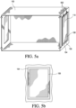
- FIG 5a provides a perspective view of an alternative arrangement of sterilizing cabinet 100 with vents 104 on the sides of the cabinet.
- filter holders 110 are located on the sides of sterilizing cabinet 100 with primary filter 108 and secondary filter 110.
- hangers 502 from which filter holder 106, primary filter 108 and secondary filter 110 attach to sterilizing cabinet 100.
- exemplary embodiments of sterilizing cabinet 100 include vents 104, primary filter 108, secondary filter 110 and filter holder 106 on the side of sterilizing cabinet 100.
- Figure 5b shows a front facing view of vent 104 with filter holder 106 overlaying vent 104 on sterilizing cabinet 100.
- filter holder 106 is sized such its edges completely cover the portions surrounding vent 104.
- Figure 5c shows primary filter 108 and filter holder 106 overlaying vent 104.
- Primary filter 108 as shown hangs from hangers 502 and attaches to filter holder 106 by clamps 504.
- Figure 5d shows secondary filter 110 in filter holder 106 overlaying primary filter 108 and vent 104.
- the portion of filter holder 106 which holds secondary filter 110 can be opened and closed through the use of hinged gasket 504 once pin 118 is removed from hole 406 maintaining the portion of filter holder 106 that holds secondary filter 110. This allows for secondary filter 110 to be removed from filter holder 106 while maintaining the position and seal of primary filter 108 over vent 104.
- Figure 6a provides a perspective view of an alternative sterilizing cabinet 100. Shown in figure 6a is sterilizing cabinet frame 112, bars 602 and hooks 604. In this embodiment there is no front side of sterilizing cabinet 100 in front of bars 602. It should be appreciated that exemplary embodiments of sterilizing cabinet 100 also include embodiments of sterilizing cabinet 100 that do not contain bars 602. In yet another exemplary embodiment of sterilizing cabinet 100, bars 602 are removeable such that bars 602 can be removeably affixed to sterilizing cabinet 100 when desired.
- Figure 6b illustrates filter door 606 which contains primary filter 106. In exemplary embodiments filter door 606 covers the front opening of sterilizing cabinet 100 in Figure 6a . Filter door 606 clamps onto sterilizing cabinet 100 with clamps 608. Bars 602 prevent the contents of sterilizing cabinet 100 (typically a tray containing instruments for sterilization) from ripping or breaking primary filter 108 and secondary filter 110.
- Figure 6c illustrates filter door 610 which attaches to filter door 606 and sterilizing cabinet 100 with the use of clamps 608.
- clamps 608 on filter door 610 fit into the spacing between clamps 608 on filter door 606. This arrangement prevents the clamps 608 from filter door 606 from interfering with clamps 608 from filter door 610.
- secondary filter 110 can be removed with filter door 610 after a sterilization cycle has completed without disturbing filter door's 606 seal with sterilizing cabinet 100.
- filter door 606 forms a seal with sterilizing cabinet 100 at the edges of the open portion of the sterilizing cabinet frame 112, such that any sterilizing steam that enters or exits sterilizing cabinet 100 during a sterilization cycle must pass through filter door 606 and primary filter 106.
- filter door 610 forms a seal with filter door 606 such that any sterilizing steam that exits sterilizing cabinet 100 and primary filter 108 must pass through filter door 610 and secondary filter 110.
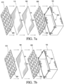
- FIG 7a depicts a perspective view of the construction of the alternative arrangement sterilizing cabinet 100 from Figures 6a, 6b and 6c .
- filter door 606 with clamps 608 attach around the frame of sterilizing cabinet 100.
- Primary filter 108 is placed on top of filter door 606 and attaches to sterilizing cabinet 100 at hooks 604.
- Secondary filter 110 is placed on top of primary filter 108 and also attaches to sterilizing cabinet 100 at hooks 604.
- Filter door 610 is then placed on top of secondary filter 110 and attached to sterilizing cabinet 100 with clamps 608.
- exemplary embodiments of filter doors 606 and 608 contain numerous holes or openings along their surface, and allow for the passage of sterilizing steam.
- Exemplary embodiments of filter doors 606 and 608 are able to be fully or partially separable from sterilizing cabinet 100. It should also be appreciated that filter doors 606 and 608 can optionally employ the use of a hinge, clamp, clasp or the like as the mechanism for removing and replacing filter doors 606 and 608 on sterilizing cabinet 100.
- FIG. 7b depicts an alternative perspective view of the construction of another alternative arrangement sterilizing cabinet 100.
- filter door 606 with clamps 608 attach around the frame of sterilizing cabinet 100.
- Primary filter 108 is placed on top of filter door 606 and attaches to sterilizing cabinet 100 at hooks 604. In this embodiment, there is only a single filter and no secondary filter.
- Primary filter 108 creates a sealed interface with filter door 606 such that extraneous materials cannot enter sterilizing cabinet 100.
- Filter door 610 is then placed on top of primary filter 108 and attached to sterilizing cabinet 100 with clamps 608.
- primary filter 108 does not create a sealed interface with filter door 606 until filter door 610 is placed on top of primary filter 108 and filter door 606.
- a sealed interface between filter door 610 and primary filter 108, and a sealed interface between filter door 606 or sterilizing cabinet 100 and primary filter 108 is only created when filter door 610 is attached or affixed to sterilizing cabinet 100.
- exemplary embodiments of filter doors 606 and 608 which contain numerous holes or openings along their surface, which allow for the passage of sterilizing steam.
- exemplary embodiments of Figure 7b provide that filter door 610 can be removed from sterilizing cabinet 100, primary filter 108 and filter door 606 without disturbing or disrupting the sealed interface between primary filter 108 and filter door 606. This will prevent the possibility of extraneous materials from entering sterilizing cabinet 100 after a sterilizing cycle when filter door 610 is removed in order to either allow primary filter 108 and filter door 606 to be removed as well or for primary filter 108 to be inspected to verify that it maintained its integrity during the sterilizing cycle.
- the sealed interface between filter door 610 and primary filter 108, and the sealed interface between filter door 606 or sterilizing cabinet 100 and primary filter 108 is broken or can be broken when filter door 610 is removed from sterilizing cabinet 100, primary filter 108, and filter door 606.
- the sealed interface between filter door 610 and primary filter 108, and the sealed interface between filter door 606 or sterilizing cabinet 100 and primary filter 108 is only created and thereafter maintained when sterilizing cabinet 100 along with filter door 610, filter door 606 and primary filter 108 are exposed to a sterilization cycle. Exemplary embodiments of sterilizing cabinet 100 as depicted in FIG.
- the sealed interface 7b are able to maintain the sealed interface between filter door 610 and primary filter 108, and the sealed interface between filter door 606 or sterilizing cabinet 100 and primary filter 108 for an extended period of time following being exposed to a sterilization cycle, such as sterilizing steam.
- the sealed interface may be able to remain intact for as long as 30-90 days. In other exemplary embodiments the sealed interface may only remain intact for a matter of hours.
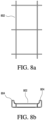
- spacer 802 for use in exemplary embodiments of sterilizing cabinet 100.
- spacer 802 has a wire frame and is sized such that when it is placed inside sterilizing cabinet 100 it does not move.
- the length and width of spacer 802 closely matches the dimensions (i.e., the depth and width) of the inside of sterilizing cabinet 100. This prevents spacer 802 from sliding or moving inside sterilizing cabinet 100 during a sterilization cycle or while sterilizing cabinet 100 is being moved.
- spacer 802 is shaped such that there are dividers or lips 804 along the edges of spacer 802 and at spacer's 802 midsection.
- the dividers or lips 804 are illustrated most clearly in Figures 8b and 8c .
- sterilizing trays can be placed on top of spacer 802 prior to a sterilization cycle.
- the dividers or lips 804 provide a physical barrier between sterilizing trays creating a minimum separation between the trays. This allows the passage sterilizing steam during a sterilization cycle throughout sterilizing cabinet 100.
- the dividers or lips 804 of spacer 802 are sized such that they accommodate the shape and size of sterilizing trays and thus substantially prevent lateral movement (e.g., sliding) of sterilizing trays when not desired before, during or following a sterilization cycle.
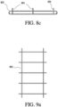
- FIGS 9a , 9b and 9c illustrate an alternative spacer 902 for use inside exemplary embodiments of sterilizing cabinet 100.
- spacer 902 is made of thin sheets (e.g., metal or aluminum alloys) with holes 906 throughout the length of the sheets.
- spacer 902 is sized such that when it is placed inside sterilizing cabinet 100 it does not move.
- the length and width of spacer 902 closely matches the dimensions (i.e., the depth and width) of the inside of sterilizing cabinet 100. This prevents spacer 902 from sliding or moving inside sterilizing cabinet 100 during a sterilization cycle or while sterilizing cabinet 100 is being moved.
- Spacer 902 is shaped such that there are dividers or lips 904 along the edges of spacer 902 and throughout spacer's 902 mid-section.
- the dividers or lips 904 can be viewed most clearly in Figures 9b and 9c .
- sterilizing trays can be placed on top of spacer 902 prior to a sterilization cycle.
- the dividers or lips 904 provide a physical barrier between sterilizing trays creating a minimum separation between the trays. This allows the passage sterilizing steam during a sterilization cycle throughout sterilizing cabinet 100.
- Holes 906 encompasses any variation of openings that allow for the passage of sterilizing steam during a sterilization cycle yet maintaining structural integrity of spacer 902 to carry the weight of the sterilizing trays and their contents.
- spacers 802 and 902 provide for the spacer to be fenestrated. In another exemplary embodiment spacers 802 and 902 are not reusable but are disposable and can only be sterilized once. In another exemplary embodiment spacers 802 and 902 provide vertical spacing between trays by at least 0.1 to 5 inches. In yet another exemplary embodiment, spacers 802 and 902 provide vertical spacing between trays by at least 10 to 26 inches.
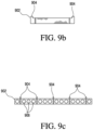
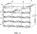
- FIG. 10 provides an exemplary embodiment of a sterilizing tray for practicing exemplary embodiments of this disclosure.
- the terms tray and pan are interchangeable and refer to an instrument with a closed rigid bottom and sides and an open top.
- Illustrated in Figure 10 is sterilizing tray 1000 with an open top and a closed rigid bottom and sides.
- Sterilizing tray 1000 can be made of any material that can be sterilized (sterilizable) and is rigid enough such that it can hold items to be sterilized.
- sterilizing tray 1000 can be made of metals or metal alloys.
- Exemplary embodiments of sterilizing tray 1000 provide for a tray that has dimensions that make it suitable for use with spacers 802 and 902 and sterilizing cabinet 100.
- Exemplary embodiments of sterilizing tray 1000 also includes trays with holes, slits, fenestrations or other openings that allow for the passage of a sterilizing agent during a sterilization cycle.
- spacers 802 or 902 can be used in conjunction with sterilizing cabinet 100 and one or more sterilizing trays 1000 during a sterilization cycle.
- the one or more sterilizing trays 1000 are of the shape and size so that they can be retained within sterilizing cabinet 100 and fit between the dividers 904 in spacers 902.
- a first tray is placed in sterilizing cabinet 100 on a spacer 902.
- spacer 902 is then placed.
- a second tray 1000 is placed in sterilizing cabinet 100 on top of spacer 902.
- the spacer 902 vertically separates the first tray 1000 from the second tray 1000 in sterilizing cabinet 100.
- Spacer 902 also inhibits lateral displacement of the first and second tray 1000 through the use of the dividers and lips 904.
- the spacers 902 play the important role of allowing sterilizing steam to pass between the sterilizing trays 1000 during a sterilization cycle.
- Exemplary embodiments of spacers 902 provide space between the first and second tray 1000 by at least 10 to 26 inches.
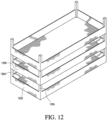
- Exemplary embodiments of these teachings also provide for a sterilizable pan assembly for sterilization within sterilizing cabinet 100.
- the sterilizable pan assembly as shown in Figure 12 illustrates a first sterilizable pan 1202 with an open top and a closed bottom. Protruding from the top of the first sterilizable pan 1202 are four legs 1204. Exemplary embodiments of the first sterilizable pan 1202 also includes legs 1204 that protrude from the bottom of the first sterilizable pan 1202. These legs are configured to releaseably attach to a portion of a second sterilizable pan 1206. Legs 1204 when attached to the second sterilizable pan 1206 maintain a vertical spacing between the bottom of the first sterilizable pan 1202 and the top of the second sterilizable pan 1206. In one exemplary embodiment the vertical spacing is at least 0.1 to 5 inches. In another exemplary embodiment, the vertical spacing is such that it allows for the passage of a sterilizing steam from a sterilization cycle of sterilizing cabinet 100. Exemplary embodiments of this pan assembly are configured such that they can be used within sterilizing cabinet 100 during a sterilization cycle.
- Filter 1302 can be made of any type of porous paper or cellulose type material. In other embodiments, filter 1302 is made of polymeric substances, such as polypropylene. Filter 1302 is required to be both porous and dense enough to allow the passage of a sterilizing agent, such as steam, through its membrane, but also resilient enough to not rip or tear during a sterilizing cycle or during insertion/clamping into a filter holder.
- a sterilizing agent such as steam
- filter 1302 is both porous and less resilient such that filter 1302 can be ripped or torn during use in a sterilizing cycle or with filter holder 106.
- the beaded edge 1304 creates a raised portion along the edges of the filter 1302 as shown in Figure 13b . This enables filter 1302 to create a sealed interface when used with sterilizing cabinet 100 and filter holder 106 over vents 104.
- beaded edge 1304 is placed inside the edge of filter 1302 rather than on the edge of filter 1302 such that there is a space between the edge of filter 1302 and beaded edge 1304.
- Exemplary embodiments of filter 1302 provide for filter 1302 to have different densities along given cross-sections of the face of filter 1302. For instance, filter 1302 may have a higher density along its periphery and a lower density towards its center. Exemplary embodiments of filter 1302 also provide for filter 1302 to have different thicknesses throughout its cross-section. The different thicknesses of filter 1302 provide different lengths of travel for sterilizing agents, which pass through filter 1302.
- Exemplary embodiments of filter 1302 have a length and width that corresponds to the size of vents 104 of sterilizing cabinet 100 and filter holder 106. Additionally, the thickness of beaded edge 1304 corresponds to a size that is able to fit between sterilizing cabinet 100 and filter holder 106 or between the different sections of filter holder 106. The thickness of beaded edge 1304 is also such that the sealed interface between sterilizing cabinet 100 and filter holder 106 or between the different sections of filter holder 106 prevents extraneous materials from entering sterilizing cabinet 100 and forces all of the sterilizing agent that enters and exits sterilizing cabinet 100 to pass through filter 1302.
- the beaded edge 1304 can be made of a silicone based material or any other material that can create a sealed interface between sterilizing cabinet 100 or filter holder 106 and filter 1302.
- the beaded edge 1304 also is required to be able to withstand high temperatures in excess of 275 degrees without compromising its structural or chemical integrity.
- Exemplary embodiments of filter 1502 have a length and width that corresponds to the size of vents 104 of sterilizing cabinet 100 and filter holder 106.
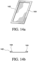
- FIG 14a provides an alternative exemplary embodiment of a filter suitable for use in practicing exemplary embodiments of this disclosure.
- Filter 1402 can be made of any type of porous paper or cellulose type material.
- filter 1402 is made of polymeric substances, such as polypropylene.
- Filter 1402 is required to be porous enough to allow the passage of a sterilizing agent, such as steam through its membrane, but also resilient enough to not rip or tear during a sterilizing cycle or during insertion/clamping into a filter holder 106.
- filter 1402 is both porous and less resilient such that filter 1402 can be ripped or torn during use in a sterilizing cycle or with filter holder 106.
- the folded edge 1404 is created by the edges of filter 1402 folded onto itself thereby creating a thicker membrane along the edges of filter 1402 as shown in Figure 14b .
- the thicker membrane of folded edge 1404 provides for a better-sealed interface between sterilizing cabinet 100 and filter holder 106 as there is less likelihood that spaces can be created between filter 1402 and sterilizing cabinet 100 which would allow for the passage of sterilizing steam or extraneous materials.
- Exemplary embodiments of filter 1402 have a length and width that corresponds to the size of vents 104 of sterilizing cabinet 100 and filter holder 106.
- the thickness of folded edge 1404 corresponds to a size that is able to fit between sterilizing cabinet 100 and filter holder 106 or between the different sections of filter holder 106.
- the thickness of edge 1404 is also such that the sealed interface between sterilizing cabinet 100 and filter holder 106 or between the different sections of filter holder 106 prevents extraneous materials from entering sterilizing cabinet 100 and forces all of the sterilizing agent that enters and exits sterilizing cabinet 100 to pass through filter 1402.
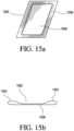
- Filter 1502 can be made of any type of porous paper or cellulose type material. In other embodiments filter 1502 is made of polymeric substances, such as polypropylene. Filter 1502 is required to be porous enough to allow the passage of a sterilizing agent, such as steam through its membrane, but also resilient enough to not rip or tear during a sterilizing cycle or during insertion/clamping into a filter holder 106. In another embodiment filter 1502 is both porous and less resilient such that filter 1502 can be ripped or torn during use in a sterilizing cycle or with filter holder 106.
- a sterilizing agent such as steam through its membrane
- filter 1502 is both porous and less resilient such that filter 1502 can be ripped or torn during use in a sterilizing cycle or with filter holder 106.
- Filter edge 1504 provides for a thicker portion of filter 1502 as shown in Figure 15b .
- the thickness of filter edge 1504 enables filter 1502 to make a better compressed sealed interface with sterilizing cabinet 100 and filter holder 106.
- Exemplary embodiments of filter 1502 have a length and width that corresponds to the size of vents 104 of sterilizing cabinet 100 and filter holder 106. Additionally, the thickness of edge 1504 corresponds to a size that is able to fit between sterilizing cabinet 100 and filter holder 106 or between the different sections of filter holder 106.
- edge 1504 is also such that the sealed interface between sterilizing cabinet 100 and filter holder 106 or between the different sections of filter holder 106 prevents extraneous materials from entering sterilizing cabinet 100 and forces all of the sterilizing agent that exits sterilizing cabinet 100 to pass through center 1506 of filter 1502.
- Center 1506 of filter 1502 includes all of the area of filter 1502 other than edge 1504 that is of normal or customary thickness for a filter that allows the passage of sterilizing steam, but prevents the passage of other extraneous materials.
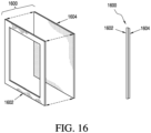
- FIG. 16 Shown in Figure 16 is an exemplary filter cartridge 1600 suitable for use in practicing exemplary embodiments of this disclosure.
- Figure 16 includes a separated view and a side view of filter cartridge 1600 in which the different elements have been separated.
- Filter cartridge 1600 includes a frame 1602 and filter 1604.
- Frame 1602 provides a substantially rigid frame that is substantially resistant from ripping or tearing.
- Frame 1602 is typically made out of a cardboard or like material.
- Frame 1602 can be made out of any type of material that is both substantially rigid and is able to maintain its integrity during and after undergoing a sterilization cycle.
- Exemplary embodiments of frame 1602 can be made out of polymer based materials or cellulose based materials. In other exemplary embodiments, frame 1602 is flexible and less rigid and may become deformed or shrink during a sterilization cycle.
- frame 1602 can be made out of any type of material that is both flexible, less rigid and is able to maintain its integrity during and after undergoing a sterilization cycle.
- frame 1602 is composed of medical grade light board.
- frame 1602 is composed of a silicone material.
- Filter 1604 can be made of any type of porous paper or cellulose type material.
- filter 1604 is made of polymeric substances, such as polypropylene. Filter 1604 is required to be porous enough to allow the passage of a sterilizing agent, such as steam through its membrane, but also resilient enough to not rip or tear during a sterilizing cycle.
- Exemplary embodiments of filter cartridge 1600 are able to provide sufficient integrity to form a sealed interface with a confronting surface, such as a sterilizing cabinet and/or a filter door or doors, and is able to maintain its integrity during and after undergoing a sterilization cycle.
- Exemplary embodiments of filter cartridge 1600 provide that frame 1602 and filter 1604 are removeably coupled to each other through the use of an adhesive.
- frame 1602 and filter 1604 are not removeably coupled, but are permanently affixed to one another or are integral with one another.
- frame 1602 and filter 1604 are removeably coupled to each other through the use of an intermediary adhesive, such as double sided tape or the like.
- Exemplary adhesives are able to create a sealed interface between frame 1602 and filter 1604 and maintain the sealed interface between frame 1602 and filter 1604 prior to, during and following a sterilization cycle.
- One exemplary adhesive suitable for use in filter cartridge 1600 is that found is U.S. Patent 3,691,140 .
- Exemplary adhesives between frame 1602 and filter 1604 create a seal between frame 1602 and filter 1604 such that extraneous materials are not able to pass between the sealed interface of frame 1602 and filter 1604.
- Exemplary adhesives between frame 1602 and filter 1604 allow for filter 1604 to be removeable when desired, typically after undergoing sterilizing cycle, such that substantially all of filter 1604 can be removed in a single piece. That is, the adhesive and materials of frame 1602 and filter 1604 are selected to provide for non-destructive separation of frame 1602 and filter 1604.
- FIG. 17 illustrated is filter cartridge 1700 suitable to use in practicing exemplary embodiments of this disclosure.
- Figure 17 includes a separated view and a side view of filter cartridge 1700 in which the different elements have been separated.
- Filter cartridge 1700 includes a frame 1702, filter 1704, and filter 1706.
- Frame 1702 provides a substantially rigid frame that is substantially resistant from ripping or tearing. In other exemplary embodiments, frame 1702 is flexible and less rigid and may become deformed or shrink during a sterilization cycle.
- Frame 1702 is typically made out of a cardboard or like material. Frame 1702 can be made out of any type of material that is both rigid and is able to maintain its integrity during and after undergoing a sterilization cycle.
- frame 1702 can be made out of polymer based materials or cellulose based materials. In another exemplary embodiment, frame 1702 can be made out of any type of material that is flexible, less rigid and is able to maintain its integrity during and after undergoing a sterilization cycle. In one exemplary embodiment, frame 1702 is composed of medical grade light board. In another exemplary embodiment, frame 1702 is composed of a silicone material.
- Filter 1704 and filter 1706 can be made of any type of porous paper or cellulose type material. In other embodiments, filter 1704 and filter 1706 are made of polymeric substances, such as polypropylene. Filter 1704 and filter 1706 are required to be porous enough to allow the passage of a sterilizing agent, such as steam through its membrane, but also resilient enough to not rip or tear during a sterilizing cycle. Exemplary embodiments of filter cartridge 1700 are able to provide sufficient integrity to form a sealed interface with a confronting surface, such as a sterilizing cabinet and/or a filter door or doors, and is able to maintain its integrity during and after undergoing a sterilization cycle.
- a sterilizing agent such as steam through its membrane
- Exemplary embodiments of filter cartridge 1700 are able to provide sufficient integrity to form a sealed interface with a confronting surface, such as a sterilizing cabinet and/or a filter door or doors, and is able to maintain its integrity during and after undergoing a sterilization cycle.
- Exemplary embodiments of filter cartridge 1700 provide that frame 1702, is removeably coupled to filter 1704 and filter 1706 through the use of an adhesive.
- frame 1702, filter 1704, and filter 1706 are not removeably coupled, but are permanently affixed to one another or are integral with one another.
- frame 1702 is removeably coupled to filter 1704 and filter 1706 through the use of an intermediary adhesive, such as double sided tape or the like.
- filter 1704 and filter 1706 are removeably coupled to frame 1702 such that they are located on opposing sides of frame 1702.
- Exemplary adhesives are able to create a sealed interface between frame 1702 and filter 1704, and between frame 1702 and filter 1706.
- Exemplary adhesive suitable for use in filter cartridge 1700 is that found is U.S. Patent 3,691,140 .
- Exemplary adhesives are also able to maintain the sealed interface between frame 1702 and filter 1704 prior to, during and following a sterilization cycle, and between frame 1702 and filter 1706 prior to, during and following a sterilization cycle.
- Exemplary adhesives between frame 1702 and filter 1704 and between frame 1702 and filter 1706 create a seal between frame 1702 and filter 1704, and between frame 1702 and filter 1706 such that extraneous materials are not able to pass between frame 1702 and filter 1704 or between frame 1702 and filter 1706.
- Exemplary adhesives between frame 1702 and filter 1704, and between frame 1702 and filter 1706 allow for filter 1604 and filter 1706 to be removeable from frame 1702 when desired, typically after undergoing sterilizing cycle, such that substantially all of filter 1704 and filter 1706 can be removed in a single piece.
- FIG. 18 shown is an exemplary filter cartridge 1800 suitable for use in practicing exemplary embodiments of this disclosure.
- Figure 18 includes a separated view and a side view of filter cartridge 1800 in which the different elements have been separated.
- Filter cartridge 1800 includes a frame 1802, frame 1804 and filter 1806.
- Frames 1802 and 1804 provide a substantially rigid frame that is substantially resistant from ripping or tearing.
- Frames 1802 and 1804 are typically made out of a cardboard or like material.
- Frames 1802 and 1804 can be made out of any type of material that is both substantially rigid and is able to maintain its integrity during and after undergoing a sterilization cycle.
- Exemplary embodiments of frames 1802 and 1804 can be made out of polymer based materials or cellulose based materials.
- frames 1802 and 1804 are flexible and less rigid and may become deformed or shrink during a sterilization cycle.
- frames 1802 and 1804 can be made out of any type of material that is flexible, less rigid and is able to maintain its integrity during and after undergoing a sterilization cycle.
- frames 1802 and 1804 are composed of medical grade light board.
- frames 1802 and 1804 are composed of a silicone material.
- Filter 1806 can be made of any type of porous paper or cellulose type material. In other embodiments filter 1806 is made of polymeric substances, such as polypropylene.
- Filter 1806 is required to be porous enough to allow the passage of a sterilizing agent, such as steam through its membrane, but also resilient enough to not rip or tear during a sterilizing cycle.
- Exemplary embodiments of filter cartridge 1800 are able to provide sufficient integrity to form a sealed interface with a confronting surface, such as a sterilizing cabinet and/or a filter door or doors, and is able to maintain its integrity during and after undergoing a sterilization cycle.
- Exemplary embodiments of filter cartridge 1800 provide that frames 1802 and 1804 are removeably coupled to filter 1806 through the use of an adhesive.
- frames 1802 and 1804, and filter 1806 are not removeably coupled, but are permanently affixed to one another or are integral with one another.
- frames 1802 and 1804 are removeably coupled to filter 1806 through the use of an intermediary adhesive, such as double sided tape or the like.
- Exemplary adhesives are able to create a sealed interface between frame 1802 and filter 1806, and between 1804 and filter 1806 and maintain the sealed interface between frame 1802 and filter 1806, and between frame 1804 and filter 1806 prior to, during and following a sterilization cycle.
- One exemplary adhesive suitable for use in filter cartridge 1800 is that found is U.S.
- Patent 3,691,140 Exemplary adhesives create a seal between frame 1802 and filter 1806, and between frame 1804 and filter 1806 such that extraneous materials do not pass between frame 1802 and filter 1806, or between frame 1804 and filter 1806. Exemplary adhesives between frame 1802 and filter 1806, and between frame 1804 and filter 1806 allow for filter 1806 to be removeable when desired, typically after undergoing sterilizing cycle, such that substantially all of filter 1806 can be removed in a single piece.
- FIG. 19 shown is an exemplary filter cartridge 1900 suitable for use in practicing exemplary embodiments of this disclosure.
- Figure 19 includes a separated view and a side view of filter cartridge 1900 in which the different elements have been separated.
- Filter cartridge 1900 includes a frame 1902, frame 1904, filter 1906 and filter 1908.
- Frames 1902 and 1904 provide a substantially rigid frame that is substantially resistant from ripping or tearing.
- Frames 1902 and 1904 are typically made out of a cardboard or like material.
- Frames 1902 and 1904 can be made out of any type of material that is both substantially rigid and is able to maintain its integrity during and after undergoing a sterilization cycle.
- frames 1902 and 1904 are flexible and less rigid and may become deformed or shrink during a sterilization cycle.
- frames 1902 and 1904 can be made out of polymer based materials or cellulose based materials.
- Frame 1902 and 1904 can be made out of any type of material that is flexible, less rigid and is able to maintain its integrity during and after undergoing a sterilization cycle.
- frames 1902 and 1904 are composed of medical grade light board.
- frames 1902 and 1904 are composed of a silicone material.
- Filters 1906 and 1908 can be made of any type of porous paper or cellulose type material. In other embodiments filters 1906 and 1908 are made of polymeric substances, such as polypropylene.
- Filters 1906 and 1908 are required to be porous enough to allow the passage of a sterilizing agent, such as steam through its membrane, but also resilient enough to not rip or tear during a sterilizing cycle.
- Exemplary embodiments of filter cartridge 1900 are able to provide sufficient integrity to form a sealed interface with a confronting surface, such as a sterilizing cabinet and/or a filter door or doors, and is able to maintain its integrity during and after undergoing a sterilization cycle.
- Exemplary embodiments of filter cartridge 1900 provide that frames 1902 and 1904 are removeably coupled to filters 1906 and 1908 through the use of an adhesive.
- frames 1902 and 1904, and filters 1906 and 1908 are not removeably coupled, but are permanently affixed to one another or are integral with one another.
- frames 1902 and 1904 are removeably coupled to filters 1906 and 1908 through the use of an intermediary adhesive, such as double sided tape or the like.
- Exemplary adhesives are able to create a sealed interface between frame 1902 and filter 1906, between frame 1904 and filter 1906, between frame 1904 and filter 1908 and also maintain the sealed interface between frames 1902 and 1904, and filters 1906 and 1908 prior to, during and following a sterilization cycle.
- Exemplary adhesive suitable for use in filter cartridge 1900 is that found is U.S. Patent 3,691,140 .
- Exemplary adhesives between frames 1902 and 1904, and filters 1906 and 1908 create a seal between frames 1902 and 1904, and filter 1906 and 1908 such that extraneous materials do not pass between frames 1902 and 1904, and filters 1906 and 1908.
- Exemplary adhesives between frames 1902 and 1904, and filters 1906 and 1908 allow for filters 1906 and 1908 to be removeable from frames 1902 and 1904 when desired, typically after undergoing sterilizing cycle, such that substantially all of filters 1906 or 1908 can be removed in a single piece.
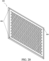
- FIG. 20 shown is an exemplary filter door for a filter cartridge suitable for use in practicing exemplary embodiments of this disclosure.
- Shown in Figure 20 is an exemplary outer filter door 2002.
- Filter door 2002 includes tabs or catches 2004, which protrude perpendicular from the back face of filter door 2002.
- Filter door 2002 as illustrated in Figure 20 contains numerous holes or openings along its surface, which allow for the passage of sterilizing steam.
- the tabs or catches 2004 are located in each of the four corners of filter door 2002. However, it should be noted that in other exemplary embodiments there can be more or less than four tabs or catches 2004. Additionally, tabs or catches 2004 can be located in different arrangements.
- Exemplary tabs or catches 2004 provide a mechanism for removeably locating or placing a filter cartridge on filter door 2002, such that a filter cartridge can be placed between tabs or catches 2004 and is in contact with tabs or catches 2004 without bending, folding or otherwise compromising the integrity of a filter cartridge.
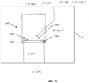
- FIG. 21 shown is a magnified cross-sectional view of an exemplary sterilizing cabinet and filter door suitable for use in practicing exemplary embodiments of this disclosure. Shown in Figure 21 is a cross-sectional view of sterilizing cabinet 2102 with trough section 2104, and filter door 2106 with trough section 2108. Exemplary embodiments of trough section 2104 and trough section 2106 run along the entire edge of sterilizing cabinet 2102 and filter door 2106.
- Trough section 2104 and trough section 2106 are shaped such that a sealed interface is maintained throughout the trough (i.e., between trough section 2104 and trough section 2106) when a single filter, multiple filters, or a filter cartridge is placed between trough section 2104 and trough section 2106.
- Exemplary embodiments of trough section 2104 and trough section 2106 have a size and depth such that the movement of extraneous materials through the sealed interface between sterilizing cabinet 2102 and filter door 2106 is substantially prevented.
- a filter cartridge may be placed and compressed between the sterilizing cabinet 2102 and filter door 2106 such that the filter cartridge is deformed into the shape of the trough in which it is compressed.
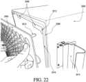
- FIG. 22 shown is a perspective view of an exemplary sterilizing cabinet and filter door suitable for use in practicing exemplary embodiments of the present disclosure. Illustrated in Figure 22 is sterilizing cabinet 2202, filter door 2204, trough section 2206, sterilizing cabinet tab 2208, filter door pin 2210, pin hole 2212, and clamp 2214. Exemplary embodiments of filter door pin 2210 are located on the top two corners of filter door 2204. In other exemplary embodiments, filter door pins 2210 are located at all four corners of filter door 2204. Filter door pins 2210 are of the size and shape to fit within pin hole 2212. Exemplary embodiments of filter door pin 2210 and pin hole 2212 are located such that filter door 2204 properly aligns and covers the open front of sterilizing cabinet 2202. Exemplary embodiments of filter door pin 2210 and pin hole 2212 maintain filter door 2204 is a loosely attached position to sterilizing cabinet 2202.
- filter door 2204 with filter door pin 2210 aligns with pin holes 2212 on sterilizing cabinet 2202 such that there is a small gap between the edge 2216 of sterilizing cabinet 2202 and filter door 2204. It can be appreciated that pin hole 2212 is located on sterilizing cabinet tab 2208. Exemplary embodiments of sterilizing cabinet tab 2208 are located at least in the four corners of sterilizing cabinet 2202 along edge 2216. In other exemplary embodiments, a sterilizing cabinet tab 2208 is also located within the middle of the vertical and horizontal edge 2216 of sterilizing cabinet 2202 such that there are eight (8) sterilizing cabinet tabs 2208. In another exemplary embodiment sterilizing cabinet 2202 includes one or more sterilizing cabinet tab 2208.
- Exemplary embodiments of sterilizing cabinet tab 2208 overlap with filter door 2204 when placed over the front opening of sterilizing cabinet 2202 such that filter door 2204 is prevented from falling or moving into the interior of sterilizing cabinet 2202 when filter door 2204 is aligned with pin hole 2212.
- Figure 22 also shows clamp 2214.
- Exemplary embodiments of clamp 2214 are located on the vertical sides of sterilizing cabinet 2202. However, exemplary embodiments of clamp 2214 can be placed in many different arrangements along the sides of sterilizing cabinet 2202 such that clamps 2214 are able to clasp and maintain filter door 2204 in a sealed position over the open front of sterilizing cabinet 2202. Exemplary embodiments of clamps 2214 are able to clasp and release filter door 2204 and an outer filter door from sterilizing cabinet 2202. Exemplary embodiments of clamp 2214 are sized such that a sealed interface is created between sterilizing cabinet 2202, a filter or filters, and the filter doors. The sealed interface prevents the passage of extraneous materials between the filter doors and sterilizing cabinet 2202.
- FIG. 23 shown is a perspective view of an exemplary sterilizing cabinet and filter door suitable for use in practicing exemplary embodiments of the present disclosure.
- FIG. 23 Shown in Figure 23 are sterilizing cabinet 2302, filter door 2304, filter cartridge 2306, clamp trough 2308, and clamp 2310.
- filter door 2304 includes clamp trough 2308 around the outer edge of filter door 2304.
- Exemplary embodiments of clamp trough 2308 align with the trough section of sterilizing cabinet 2302 when filter door 2304 covers the opening of sterilizing cabinet 2302.
- clamp trough 2308 is sized and located such that clamp 2310 is able to latch, clamp or otherwise hook onto filter door 2304 through clamp trough 2308.
- Exemplary embodiments of clamp trough 2308 provides a lip or trough that substantially prevents clamp 2310 from slipping when clamp 2310 clamps onto filter door 2304.
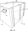
- FIG. 24 shown is a bottom perspective view of an exemplary sterilizing cabinet suitable for use in practicing exemplary embodiments of the present disclosure. Shown in Figure 24 are sterilizing cabinet 2402, sterilizing cabinet tabs 2404, clamp 2406 and legs 2408. Exemplary embodiments of legs 2408 reside on the bottom of sterilizing cabinet 2402 and provide a stable foundation for sterilizing cabinet 2402 to rest on a surface. Exemplary embodiments of legs 2408 further include holes 2410. Holes 2410 provide a means for attaching legs 2408 and thus sterilizing cabinet 2402 to a surface. For example, sterilizing cabinet 2402 through holes 2410 on legs 2408 can be screwed, bolted, attached, or nailed onto a table, counter, or other flat surface large and structurally sturdy enough to maintain sterilizing cabinet 2402.
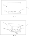
- FIG. 25 shown is a perspective view of an alternative embodiment of a sterilizing cabinet suitable for use in practicing exemplary embodiments of this disclosure. Shown in Figure 25 are sterilizing cabinet 2502, frame 2504, filter door 2506, latches 2508, and filter 2510. As illustrated, sterilizing cabinet 2502 is maintained within frame 2504.
- Frame 2504 provides a structurally reinforcing frame for sterilizing cabinet 2502. Exemplary embodiments of frame 2504 are able to securely maintain sterilizing cabinet 2502 such that all of the sides/corners of sterilizing cabinet 2502 are supported by frame 2504.
- Exemplary embodiments of frame 2504 are made of any type of metal, plastic, composite, or aluminum alloy. Exemplary embodiments of frame 2504 are able to repeatedly undergo sterilizing cycles (e.g., steam sterilizing cycles) and maintain its structural integrity.
- sterilizing cycles e.g., steam sterilizing cycles
- Filter door 2506 attaches to frame 2504 through the use of latches 2508.
- latches 2508 can include any type of clamping, latching or clasping device known in the art that is able to releasable attach filter door 2506 to frame 2504 such that a sealed interface is created between filter door 2506 and sterilizing cabinet 2502.
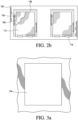
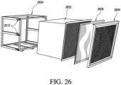
- FIG. 26 shown is a perspective view of a separated alternative embodiment of a sterilizing cabinet suitable for use in practicing exemplary embodiments of this disclosure. Shown in Figure 26 are sterilizing cabinet 2602, frame 2604, filter door 2606, filter cartridge 2608, and latches 2610.
- sterilizing cabinet 2602 can be removed from frame 2604 when filter door 2606 is released from removable frame 2604 by latches 2610.
- frame 2604 is not removable from sterilizing cabinet 2602, but is fixedly attached to sterilizing cabinet 2602.
- Filter door 2606 as depicted includes a fenestrated grid throughout its center.
- exemplary embodiments of filter door 2606 include any type of arrangement of holes, gaps, or grids such that sterilizing steam is free to pass through the center portion of filter door 2606.
- filter cartridge 2608 is maintained between filter door 2606 and sterilizing cabinet 2602. As previously stated above, filter cartridge 2608 is placed between filter door 2606 and sterilizing cabinet 2602 creating a sealed interface around its edges such that sterilizing steam is not able to pass between the sealed interface, but can only pass through the center of filter cartridge 2608.
- FIG. 27 illustrated is a side view of an embodiment of a sterilizing cabinet in an autoclave 10. Shown in Figure 27 is a sterilizing cabinet 2702 with bottom 2704, front legs 2706, and back legs 2708. Front legs 2706 and back legs 2708 as shown in Figure 27 are pegs or stands fixedly attached to bottom 2704 of sterilizing cabinet 2702, which provide support for sterilizing cabinet 2702 when placed on a substantially planar surface. As shown in Figure 27 , there are two front legs 2706 and two back legs 2708. However, it should be appreciated that exemplary embodiments of front legs 2706 and back legs 2708 can include one or more than one leg or support provided that front legs 2706 are shorter than back legs 2708 which in turn tilts or angles bottom 2704 toward the front of sterilizing cabinet 2702.
- front legs 2706 and back legs 2708 include any arrangement resulting in bottom 2704 not being a level surface but tilted, inclined, towards a vent port of sterilizing cabinet 2702.
- the bottom 2704 is sufficiently inclined to induce a flow of condensate to and through the vent port.
- sterilizing cabinet 2702 includes a single front leg 2706 that spans or substantially spans the front width of sterilizing cabinet 2702, and a single back leg 2708 that spans or substantially spans the back width of sterilizing cabinet 2702.
- sterilizing cabinet 2702 includes two front legs 2706 located in opposite front corners of bottom 2704 of sterilizing cabinet 2702, and a single back leg 2708 located in the middle or substantially the middle of the back of bottom 2704 of sterilizing cabinet 2702.
- sterilizing cabinet 2702 can include actuators, such as servos, pistons, or lifts that can be remotely engaged to tilt the bottom 2704 to selectively induce flow along the bottom to the vent port.
- actuators such as servos, pistons, or lifts that can be remotely engaged to tilt the bottom 2704 to selectively induce flow along the bottom to the vent port.
- Exemplary embodiments of bottom 2704 provide a flat surface that when tilted, towards the front of sterilizing cabinet 2702 which contains a vent port and a filter, allows a liquid, such as condensate to flow along bottom 2704 to and through the filter and out of sterilizing cabinet 2702.
- a liquid such as condensate
- sterilizing cabinet 2702 is placed in an autoclave or other known sterilizing device. The autoclave is then shut and sterilizing steam passes through a filter or filters overlaying a front vent port to the interior of sterilizing cabinet 2702 at which point the sterilizing steam comes into contact with any items or materials within the interior of sterilizing cabinet 2702.
- This process can produce a substantial amount of condensate within the interior of sterilizing cabinet 2702, which can collect on the bottom 2704 of sterilizing cabinet 2702.
- approximately 12 ounces of condensate may be produced for every 15 pounds of load maintained within sterilizing cabinet 2702 during a sterilization cycle of the autoclave.
- Exemplary embodiments of bottom 2704 provide a surface that allows the condensate to flow or move freely towards a filter on sterilizing cabinet 2702, such as the front of the cabinet, so that the condensate can exit the interior of sterilizing cabinet 2702.
- Exemplary embodiments of the sterilizing cabinet 2702 further provide for at least a substantial portion, and in select configurations all of the condensate within sterilizing cabinet 2702 to have exited sterilizing cabinet 2702 prior to the opening of the autoclave 10 or other sterilizing device.
- sterilizing cabinet 2702 contains an industry acceptable amount of condensate following a sterilizing cycle, when the autoclave is opened.
- Exemplary embodiments of bottom 2704 also include surfaces that are not substantially flat, but have channels, features or minor curves that move or allow to move condensate or accumulated condensate to a vent port of sterilizing cabinet 2702 through a filter or to another predetermined outlet or filtered drain that exits the interior of sterilizing cabinet 2702.
- FIG. 28 Shown in Figure 28 is sterilizing cabinet 2802, bottom 2804, front legs 2806, back legs 2808, and raised floor 2810 within the autoclave 10.
- front legs 2806 and back legs 2808 are the same length or height such that bottom 2804 as well as sterilizing cabinet 2802 is level when placed on a level planar surface.
- Raised floor 2810 as depicted is located above bottom 2804 in the interior of sterilizing cabinet 2802.
- Raised floor 2810 in one embodiment is substantially planar. Exemplary embodiments of raised floor 2810 provide a surface that allows or moves a flow of condensate toward a vent port located on the front of sterilizing cabinet 2802 and through the filter overlying the vent port. In another exemplary embodiment, raised floor 2810 is a surface that is not substantially planar, but is curved or has minor curves, or flow channels that moves or allows to move a flow of condensate or accumulated condensate to a vent port of sterilizing cabinet 2802 or to another predetermined outlet or filtered drain that exits the interior of sterilizing cabinet 2802.
- FIG. 29 Shown in Figure 29 is the interior of sterilizing cabinet 2802 with bottom 2804, and raised floor 2810 within the autoclave 10. As is shown, raised floor 2810 is above bottom 2804 and is angled relative to bottom 2804 such that a flow of condensate is directed toward the vent port of sterilizing cabinet 2802. It should be appreciated that exemplary embodiments of raised floor 2810 can include both substantially planar and curved or featured (with channels) embodiments that direct condensate toward a vent port on sterilizing cabinet 2802, or toward another outlet that allows condensate to drain or exit the interior of sterilizing cabinet 2802.
- Raised floor supports 2812 provide support for the position of raised floor 2810 with sterilizing cabinet 2802.
- raised floor supports 2812 are beams located under raised floor 2810 that are connected to raised floor 2810 and bottom 2804 to maintain the position of raised floor 2810. It should be appreciated that raised floor supports 2812 can include any known beam or support that is able to maintain the position of raised floor 2810 with the weight of the anticipated loaded sterilizing cabinet 2802, which can be up to a 250 pound load or more.
- raised floor 2810 is flush with the bottom of vent port 2814.
- Exemplary embodiments of raised floor 2810 include instances wherein raised floor 2810 is flush or nearly flush with the bottom of vent port 2814.
- Exemplary embodiment of raised floor 2810 are positioned relative to the bottom of vent port 2814 such that a flow of condensate along raised bottom 2810 can move and progress through vent port 2814.
- Raised floor 2810 in the embodiment shown is tilted or angled relative to bottom 2804 toward vent port 2814 such that any fluid or condensate on raised floor 2810 is moved towards vent port 2814.
- the autoclave receives the sterilizing cabinet and subjects the sterilizing cabinet to a sterilization cycle.
- the sterilization can include, but is not limited to heat, steam, pressure, gas, plasma, irradiation, chemical components, chemical vapor or combinations thereof.
- the sterilizing cabinet is retained within the autoclave, and the interior environment of the autoclave is controlled to provide a sterilization cycle.
- the autoclave typically creates a sealed environment which is thus applied to the retained sterilizing cabinet. The autoclave thus subjects the sterilizing cabinet and the interior of the sterilizing cabinet to the sterilization cycle.
- the interface between the filters and the sterilizing cabinet is effectively sealed either prior to or during or at the completion of_the sterilization cycle. That is, at least before the autoclave is opened, a sealed interface is formed between the seals and the sterilizing cabinet. It is understood the seal between the filter and the sterilizing cabinet may go through a transformation during the sterilization cycle. When the filter is initially operably located relative to the sterilizing cabinet, a seal can be formed. However, it is contemplated that the initial operable location of the seal relative to the sterilizing cabinet may not form a seal, wherein the sealed interface is formed during the sterilization cycle or at the completion of the sterilization cycle.
- the seal when exposed to the sterilization cycle, (in select cases, heat in the form of steam, and pressure) may under goes slight transformation of the seal configuration, and either becomes more form fitting to the sealing surface area or even results in seal formation. This change in the seal during the sterilization cycle may create a more robust seal than when it was originally placed. It is contemplated a variety of materials can be used to enhance or form a seal between the filter (or the cartridge) and the sterilizing cabinet, such as but not limited to card stocks, thermoplastics, thermoplastic elastomers, polymers and waxes.
- the interface between the filters and the sterilizing cabinet can be dynamic, forming a seal during the sterilization cycle, or static, entering the sterilization cycle with the sealed interface and maintaining the sealed interface throughout the sterilization cycle.
- the interior of the sterilizing cabinet should have no more than a certain amount of moisture and a seal exist between any filter, or cartridge and the sterilizing cabinet.
- a sterilizing cabinet it is advantageous for a sterilizing cabinet to have only an amount of condensate that can be driven off or evaporated by the autoclave during a normal, or given or predetermined sterilizing cycle of the autoclave or during the post-sterilization cool down period.
- the inclined surface in the sterilizing cabinet induces a flow of the condensate to and through a port, such as a filter.
- the cycle time can be decreased by facilitating the removal of condensate from the sterilizing cabinet during the sterilization cycle. That is, by draining condensate from the sterilizing cabinet during the sterilization cycle, the amount of condensate to be evaporated from within the sterilizing cabinet during the sterilization cycle, or during the post-sterilization cool down period, is decreased, thereby increasing efficiency of the process.
Description
- Exemplary embodiments of the present invention relate to a method and apparatus for sterilization and more particularly to a method and apparatus for sterilization of instruments.
- Sterilization is a term referring to any process that eliminates (removes) or kills microbial life, including transmissible agents (such as fungi, bacteria, viruses, or spore forms) present on a surface, or contained in a fluid, or in medication, or in a compound such as biological culture media. Sterilization can be achieved by applying heat, chemicals, irradiation, high pressure, and filtration or combinations thereof.
- In general, surgical instruments and medications that enter an already aseptic part of the body (such as the bloodstream, or penetrating the skin) must be sterilized to a high sterility assurance level. Examples of such instruments include scalpels, hypodermic needles and implantable medical devices (IMD), such as artificial pacemakers.
- A widely used method for heat sterilization is the autoclave, sometimes referred to as a converter. Autoclaves commonly use steam heated to 121-134 °C. To achieve a degree of sterility, a holding time of at least 15 minutes at 121 °C at 100 kPa, or 3 minutes at 134 °C at 100 kPa is required. Additional sterilizing time is usually required for liquids and instruments packed in layers of cloth, as they may take longer to reach the required temperature.
- One method of sterilization involves passing steam through a cabinet. For effective sterilization, steam needs to penetrate the cabinet load uniformly. Accordingly, the cabinet must not be overcrowded, and the lids of bottles and containers must be left ajar. During the initial heating of the chamber, residual air must be removed. Indicators should be placed in the most difficult places for the steam to reach to ensure that steam actually penetrates there.
- A filter is typically placed over the vent to keep particles or extraneous materials from entering the cabinet before, during or after the sterilizing process. Once the sterilizing process is completed the filter needs to be removed and inspected by medical professionals to verify the integrity of the sterilizing process was maintained. If it is discovered during inspection that the filter did not remain intact, the sterilizing process has to be repeated with a new filter.
-
US 8 454 901 B1 discloses a mobile apparatus and method to sterilize surgical trays. A cabinet has filtered cabinet roof vents, filtered cabinet floor vents, doors sealably covering a cabinet front aperture, shelves sized to support surgical trays, and wheels. Surgical trays are placed within the cabinet, the cabinet doors are closed, and the mobile apparatus is placed within an autoclave and sterilized. The cabinet doors are not unsealed until the cabinet is in the operating room, ready for use. During use in the operating room, doors are opened, trays removed, and their contents used. Wheels on the cabinet facilitate moving the cabinet from autoclave to storage or operating room. Method steps include periodically replacing the filters and door gasket. -
US 2014/0348722 A1 discloses a surgical sterilizing container, which consists of a container tub having a bottom, an outer wall protruding from the bottom, and a lid. The bottom includes a fluid drainage surface such that fluid, in particular, condensate formed during the sterilization process, is drained off from the fluid drainage surface into depressions located at the transverse side wall. Fluid is lifted out of the fluid collection area by a fluid lifting device and conducted to an outlet valve to remove fluid from the container interior. - A high temperature and pressure steam sterilization container for an endoscope is described in
US 2005/0000553 A1 . In an embodiment of the invention, the sterilization container includes a tray that can store materials to be cleaned and sterilized such as an endoscope. The tray may include a lid that is separated or a lid that is integral to the tray. The tray may be placed in an endoscope treatment chamber and a machine chamber. In a first treatment section, the endoscope in the tray is cleaned or cleaned and disinfected. In a second treatment section, the endoscope in the tray is sterilized. In the second treatment section, the tray is detachably connected to a tray connecting portion and a discharge port is detachably connected to a solution discharge valve of the tray. -
JP 2009 285 009 A -
US 4 728 504 A discloses a medical instruments sterilization container, which includes a housing and a removable dome-shaped lid having a filtered inlet port disposed therethrough for permitting the passage of gas or steam into housing. A removable tray is adapted to be disposed within housing to hold various instruments to be sterilized and includes apertures formed on the bottom of the tray for permitting condensate to drain therefrom. The bottom surface of housing is sloped to two locations centred on opposite sides thereof and includes filtered outlet ports positioned at the two locations to permit discharged air and condensate to exit housing. - In view of the foregoing, it is an object of the present invention to provide a method and apparatus for sterilization.
- A sterilizing cabinet assembly according to the invention is defined by claim 1. A method of sterilizing using the sterilizing cabinet assembly according to the invention is defined by claims 5 and 7. Preferred embodiments of the invention are defined by claims 2 to 4, 6, and 8.
- The invention provides a sterilizing cabinet assembly, including a cabinet having an access port and a bottom; a door connected to the cabinet, the door moveable between an open position permitting passage through the access port to an interior of the cabinet and a closed position precluding passage through the access port; the door having a vent port, wherein the bottom induces condensate on the bottom to flow to the vent port; and a filter overlying the vent port and forming a sealed interface with an adjacent portion of the door.
- The invention further provides a method of sterilizing, which includes occluding a vent port of the sterilizing cabinet with a filter, the sterilizing cabinet having an internal inclined surface to induce a condensate flow to the vent port; performing a sterilization cycle on the sterilizing cabinet; and draining at least a portion of a condensate formed in the sterilization cycle along the inclined surface to pass from the sterilizing cabinet through the filter.
- Another method according to the invention includes locating a sterilizing cabinet in an autoclave; applying a sterilization cycle to the sterilizing cabinet in the autoclave; and draining along an inclined surface in the sterilizing cabinet at least a portion of a condensate from the sterilizing cabinet during the sterilization cycle.
- The following will describe embodiments of the present invention, but it should be appreciated that the present invention is not limited to the described embodiments and various modifications of the invention are possible without departing from the basic principle. The scope of the present invention is therefore to be determined solely by the appended claims.
-
-
Figure 1a is a front view of a configuration of a sterilizing cabinet suitable for use in practicing exemplary embodiments of this disclosure. -
Figure 1b is a top view of a configuration of a sterilizing cabinet suitable for use in practicing exemplary embodiments of this disclosure. -
Figure 1c is a side view of a configuration of a sterilizing cabinet suitable for use in practicing exemplary embodiments of this disclosure. -
Figure 2a is a perspective view of an alternative configuration of a sterilizing cabinet suitable for use in practicing exemplary embodiments of this disclosure. -
Figure 2b is a top view of an alternative configuration of a sterilizing cabinet suitable for use in practicing exemplary embodiments of this disclosure. -
Figure 3a is a top view of a vent of a sterilizing cabinet suitable for use in practicing exemplary embodiments of this disclosure. -
Figure 3b is a perspective view of a filter arrangement of a sterilizing cabinet for use in practicing exemplary embodiments of this disclosure. -
Figure 4a is a perspective view of the movement of a filter arrangement of a sterilizing cabinet for use in practicing exemplary embodiments of this disclosure. -
Figure 4b is a perspective view of the movement of an alternative filter arrangement of a sterilizing cabinet for use in practicing exemplary embodiments of this disclosure. -
Figure 5a is a perspective view of an alternative configuration of a sterilizing cabinet suitable for use in practicing exemplary embodiments of this disclosure. -
Figure 5b is a perspective view of bottom section of a filter arrangement of a sterilizing cabinet suitable for use in practicing exemplary embodiments of this disclosure. -
Figure 5c is a perspective view of a middle section of a filter arrangement of a sterilizing cabinet suitable for use in practicing exemplary embodiments of this disclosure. -
Figure 5d is a perspective view of top section of a filter arrangement of a sterilizing cabinet suitable for use in practicing exemplary embodiments of this disclosure. -
Figure 6a is a perspective view of an alternative sterilizing cabinet suitable for use in practicing exemplary embodiments of this disclosure. -
Figure 6b is a front view of an alternative filter arrangement of a sterilizing cabinet suitable for use in practicing exemplary embodiments of this disclosure. -
Figure 6c is a front view of the top portion of an alternative filter arrangement of a sterilizing cabinet suitable for use in practicing exemplary embodiments of this disclosure. -
Figure 7a is a perspective view of the separated elements of an alternative filter arrangement of a sterilizing cabinet suitable for use in practicing exemplary embodiments of this disclosure. -
Figure 7b is a perspective view of the separated elements of another filter arrangement of a sterilizing cabinet suitable for use in practicing exemplary embodiments of this disclosure. -
Figure 8a is a top view of a spacer suitable for use in practicing exemplary embodiments of this disclosure. -
Figure 8b is a side view of a spacer suitable for use in practicing exemplary embodiments of this disclosure. -
Figure 8c is another side view of a spacer suitable for use in practicing exemplary embodiments of this disclosure. -
Figure 9a is a top view of an alternative spacer suitable for use in practicing exemplary embodiments of this disclosure. -
Figure 9b is a side view of an alternative spacer suitable for use in practicing exemplary embodiments of this disclosure. -
Figure 9c is another side view of an alternative spacer suitable for use in practicing exemplary embodiments of this disclosure. -
Figure 10 is a perspective view of a sterilizing tray suitable for use in practicing exemplary embodiments of this disclosure. -
Figure 11 is a perspective view of a sterilizing cabinet suitable for use in practicing exemplary embodiments of this disclosure. -
Figure 12 is a perspective view of a pan assembly suitable for use in practicing exemplary embodiments of this disclosure. -
Figure 13a is a perspective view of a filter suitable for use in practicing exemplary embodiments of this disclosure. -
Figure 13b is a side view of a filter suitable for use in practicing exemplary embodiments of this disclosure. -
Figure 14a is a perspective view of an alternative filter suitable for use in practicing exemplary embodiments of this disclosure. -
Figure 14b is a side view of an alternative filter suitable for use in practicing exemplary embodiments of this disclosure. -
Figure 15a is a perspective view of another filter suitable for use in practicing exemplary embodiments of this disclosure. -
Figure 15b is a side view of another filter suitable for use in practicing exemplary embodiments of this disclosure. -
Figure 16 is a perspective view of a filter cartridge suitable for use in practicing exemplary embodiments of this disclosure. -
Figure 17 is a perspective view of an alternative filter cartridge suitable in practicing exemplary embodiments of this disclosure. -
Figure 18 is a perspective view of an alternative filter cartridge suitable in practicing exemplary embodiments of this disclosure. -
Figure 19 is a perspective view of another filter cartridge suitable in practicing exemplary embodiments of this disclosure. -
Figure 20 is a filter cartridge holder suitable in practicing exemplary embodiments of this disclosure. -
Figure 21 is a magnified cross-sectional view of sterilizing cabinet and a filter door suitable for use in practicing exemplary embodiments of this disclosure. -
Figure 22 is a perspective view of an exemplary sterilizing cabinet and filter door suitable for use in practicing exemplary embodiments of the present disclosure. -
Figure 23 is a perspective view of an exemplary sterilizing cabinet and filter door suitable for use in practicing exemplary embodiments of the present disclosure. -
Figure 24 is a bottom perspective view of an exemplary sterilizing cabinet suitable for use in practicing exemplary embodiments of the present disclosure. -
Figure 25 is a perspective view of an alternative embodiment of a sterilizing cabinet suitable for use in practicing exemplary embodiments of this disclosure. -
Figure 26 is a perspective view of a separated alternative embodiment of a sterilizing cabinet suitable for use in practicing exemplary embodiments of this disclosure. -
Figure 27 is a side view of an embodiment of a sterilizing cabinet according to the present invention which is suitable for use in practicing exemplary embodiments of this invention. -
Figure 28 is another embodiment of a sterilizing cabinet according to the present invention which is suitable for use in practicing exemplary embodiments of this invention. -
Figure 29 is an internal view of an exemplary sterilizing cabinet according to the present invention which is suitable for use in practicing exemplary embodiments of this invention. -
Figure 30 is a front perspective view of an exemplary sterilizing cabinet according to the present invention which is suitable for use in practicing exemplary embodiments of this invention. - In the medical field, it is of the utmost importance that medical instruments are sterilized prior to any medical procedure. This drastically helps prevent the spread of infectious materials. In the marketplace, there are a wide variety of devices that provide for sterilization of medical instruments through the use of a sterilizing agent, such as steam. Instrument trays can be wrapped in a cloth or paper that acts as a filter, allowing the tray to be sterilized, then delivered to the operating room. Alternatively, a rigid container can contain the instrument tray. Typically, the device (e.g., a rigid container) contains a vent for venting the steam used to sterilize the contents of the device. A disposable filter usually covers these vents. The filters have two major purposes. First, they prevent extraneous materials from entering the sterilizing device during and after the sterilization cycle. Second, they allow sterilizing steam to enter and exit the sterilizing device.
- However, in order to check that the integrity of the sterilization cycle has been maintained a person (usually a medical technician) must verify that there are no holes or other types of rips in the filter. This is done by removing the filter from the sterilizing device and visually inspecting the filter. This creates an inherent time period wherein the sterilized instruments can be contaminated by extraneous materials that enter the sterilizing device through the now open and uncovered vents. An object of exemplary embodiments of this disclosure provide a solution to this problem.
- Referring to
Figure 1a , is a front view of sterilizingcabinet 100. It should be noted that embodiments of the present invention are not limited to the particular configuration of sterilizingcabinet 100. - The
term sterilizing cabinet 100 encompasses any device capable of sterilizing. The term also includes sterilizing cabinets for sterilizing medical instruments, surgical devices and the like. - Sterilizing
cabinet 100 includes door ordoors 102, vents 104,filter holder 106,primary filter 108,secondary filter 110, sterilizingcabinet frame 112 andlegs 114. Door ordoors 102 are able to open and close for access to the interior of sterilizingcabinet 100. Door ordoors 102 are physically connected to sterilizingcabinet frame 112. Door ordoors 102 can be attached through the use of a hinge or hinges which allows the doors to swing open. Alternatively, door ordoors 102 can be removable from sterilizingcabinet 100 through the use of clamps (not shown inFigure 1 ). It should be appreciated that exemplary embodiments of door ordoors 102 include any mechanism that allows for door ordoors 102 to move from an open position to a closed position to provide access to the interior of sterilizingcabinet 100. - Sterilizing
cabinet 100 in this embodiment provides for fourvents 104. However, it should be appreciated that exemplary embodiments of sterilizingcabinet 100 are not limited to four vents. Exemplary embodiments of sterilizingcabinet 100 can include one or more vents. Twovents 104 on the top of sterilizingcabinet 100 and twovents 104 on the bottom of sterilizingcabinet 100.Vents 104 provide numerous small openings for the passage of sterilizing steam. The small openings invents 104 can be holes or slits. Alternatively, vents 104 can be fenestrated. -
Primary filter 108 in conjunction withfilter holder 106 covers vent 104.Primary filter 108 withfilter holder 106 forms a seal with the adjacent portions of sterilizingcabinet 100 such that during the operation of a sterilizing cycle, any sterilizing steam that passes through thevent 104 must then pass throughprimary filter 108.Primary filter 108 can be made of a very thin paper. Exemplary embodiments provide thatprimary filter 108 can be made of any porous material that (1) allows for the passage of sterilizing steam from sterilizingcabinet 100 and (2) prevents extraneous materials from passing throughprimary filter 108 and enteringvent 104.Primary filter 108 is removable from sterilizingcabinet 100 and is typically replaced with a new filter following each sterilizing cycle. -
Secondary filter 110 resides on top ofprimary filter 108 infilter holder 106.Secondary filter 110 coversprimary filter 108 and forms a seal withprimary filter 108 throughfilter holder 106 such that any sterilizing steam that passes through thevent 104 must then pass throughprimary filter 108 andsecondary filter 110.Secondary filter 110 can be made of a very thin paper.Secondary filter 110 can be made of any porous material that (1) allows for the passage of sterilizing steam from sterilizingcabinet 100 andprimary filter 108 and (2) prevents extraneous materials from passing throughsecondary filter 108. - Exemplary embodiments of this disclosure provide for
secondary filter 110 to form a sealed periphery withprimary filter 108. In another exemplary embodiment the sealed interface between theprimary filter 108 and the adjacent portion of either the sterilizingcabinet 100 is independent of an interface betweensecondary filter 110 andprimary filter 108. One exemplary arrangement provides forprimary filter 108 andsecondary filter 110 to be coextensive. In another exemplary embodimentprimary filter 108 andsecondary filter 110 have different filter properties. For instance,primary filter 108 andsecondary filter 110 may filter different elements of the sterilizing agent which exits sterilizingcabinet 100 during a sterilization cycle. In an alternative exemplary embodimentprimary filter 108 andsecondary filter 110 have similar filter properties. Another exemplary embodiment provides thatprimary filter 108 andsecondary filter 110 are different colors. - In yet another exemplary embodiment,
primary filter 108 may be the only filter that coversvent 104. Here,primary filter 108 is removeably held or maintained in place overvent 104 byfilter holder 106. In this embodiment, there is no secondary filter.Primary filter 108 forms a seal with the adjacent portions of sterilizingcabinet 100 such that during the operation of a sterilizing cycle, any sterilizing steam that passes through thevent 104 must then pass throughprimary filter 108. Again, in this embodiment,primary filter 108 can be made of any porous material that (1) allows for the passage of sterilizing steam from sterilizingcabinet 100 and (2) prevents extraneous materials from passing throughprimary filter 108 and enteringvent 104.Primary filter 108 is removable from sterilizingcabinet 100 and is typically replaced with a new filter following each sterilizing cycle. -
Legs 114 reside on the bottom of sterilizingcabinet 100 and provide spacing between the surface which sterilizingcabinet 100 rests and the bottomprimary filter 108,secondary filter 110 andfilter holder 106. -
Figure 1b provides a top view of sterilizingcabinet 100 showingvent 104 covered byfilter holder 106,primary filter 108,secondary filter 110, sterilizingcabinet frame 112 and hinge 116 offilter holder 106.Hinge 116 withfilter holder 106 allows a portion offilter holder 106 to swing open abouthinge 116 such thatprimary filter 108 andsecondary filter 110 can be removed independent of one another. In other words,filter holder 106 allows forsecondary filter 110 to be released and removed fromfilter holder 106 while simultaneously maintaining primary filter's 108 seal with sterilizingcabinet 100 overvent 104. -
Figure 1c shows a side view of sterilizingcabinet 100 including sterilizingcabinet frame 112, vent 104,primary filter 108,secondary filter 110,filter holder 106 and hinge 116. - In exemplary
embodiments sterilizing cabinet 100 may include a steam exposure indicator on either theprimary filter 108 or thesecondary filter 110 which designates when steam from sterilizingcabinet 100 has passed through one of the filters. An example of one such steam exposure indicator is a tape that changes colors when exposed to steam. -
Figure 2a provides a perspective view of sterilizingcabinet 100 with twovents 104 on the top and twovents 104 on the bottom of sterilizingcabinet 100.Figure 2a also includesprimary filters 108 occludingvents 104 andsecondary filters 110 overlayingprimary filters 108 withprimary filters 108 andsecondary filters 110 each infilter holders 106. -
Figure 2b provides a top view of sterilizingcabinet 100 with an alternative exemplary embodiment offilter holder 106. Shown inFigure 2b are twovents 104 occluded byprimary filters 108 which are also covered bysecondary filters 110. In this exemplaryembodiment filter holders 106 do not have a swinging hinge which allows for the individual attachment and release ofprimary filters 108 andsecondary filters 110. In this exemplaryembodiment filter holders 106 allow for independently removingprimary filter 108 andsecondary filter 110 through the use of a sliding mechanism.Secondary filter 110 can be removed by sliding it out offilter holder 106 while maintaining primary filter's 108 seal with sterilizingcabinet 100 aroundvent 104. - In another alternative exemplary embodiment,
filter holder 106 again does not include a swinging hinge, but allows for the placement and removal of onlyprimary filter 108 by a sliding mechanism. In this embodiment, there is nosecondary filter 110. Onlyprimary filter 108 in conjunction withfilter holder 106 forms a sealed interface with sterilizingcabinet 100 occluding vents 104.Primary filter 108 can then be placed or removed by sliding into and out offilter holder 106. - In practice, an exemplary embodiment of a process of placing
primary filter 108 andsecondary filter 110 includes disposingprimary filter 108 to occlude avent 104 of sterilizingcabinet 100 and forming a first sealed interface with the sterilizingcabinet 100. The process continues by forming a second sealed interface between secondary filter 110 (or confirmatory filter) and at least a portion of one of sterilizingcabinet 100 andprimary filter 108, a portion of thesecondary filter 110 overlying a portion of theprimary filter 108. The process can continue by passing a sterilizing agent (typically steam) throughprimary filter 108 andsecondary filter 110 and vent 104. - Also in practice, an exemplary embodiment of a process of placing only a
primary filter 108 includes disposingprimary filter 108 withfilter holder 106 to occludevent 104 of sterilizingcabinet 100 creating a sealed interface with the sterilizingcabinet 100. The process can continue by passing a sterilizing agent (typically steam) throughprimary filter 108 and vent 104. The process can then conclude with verifying the integrity ofprimary filter 108 by either inspectingprimary filter 108 while it coversvent 104 infilter holder 106 or after it is removed fromfilter holder 106. The process may be repeated if it is determined that the integrity ofprimary filter 108 was compromised during the sterilizing process. - Exemplary embodiments of inspecting
primary filter 108 and/orsecondary filter 110 can include visual inspection by either medical or non-medical personnel, inspecting by an electronic device or machine, or inspecting through mechanical means. Exemplary embodiments of inspecting by an electronic device or machine includes any type of device that is able to scan or image theprimary filter 108 and/orsecondary filter 110 such that the scanned or imaged picture of theprimary filter 108 and/orsecondary filter 110 can be digitally viewed or examined for imperfections such as rips or cuts that would impact the integrity of the sterilization cycle. Exemplary embodiments of mechanical inspection includes any type of inspection means that physically test that the integrity of theprimary filter 108 and/orsecondary filter 110 has been maintained. - It should be noted that exemplary embodiments of a sterilizing agent include any substance that provides for the destruction or elimination of living organisms, which often include heat, steam, pressure, gas, plasma, irradiation, chemical compounds, and chemical vapor.
- Exemplary embodiments of this process provide that the first sealed interface is separate from the second sealed interface. Additionally, failure of the second sealed interface is independent of the first sealed interface. For example, if the second sealed interface fails and leaks sterilizing steam during a sterilization cycle, the first sealed interface should remain intact and should not be affected by the failure of the second sealed interface.
- Referring to
Figure 3a , a top view of anexemplary vent 104 is shown. Provided is a fenestrated surface with numerous openings that allow for the passage of a sterilizing agent, such as steam from sterilizingcabinet 100 during a sterilization cycle. It can be appreciated thatFigure 3a merely represents one embodiment ofvent 104 and that exemplary embodiments ofvent 104 include any arrangement of holes or openings that allow for the passage of a sterilizing agent. -
Figure 3b provides a top view of a filteringarrangement covering vent 104. Shown inFigure 3b is the top portion ofsecondary filter 110,filter holder 106 withhinges 116 andpin 118. Exemplary embodiments of this arrangement provide for a silicon seal betweenfilter holder 106 andprimary filter 108, betweenfilter holder 106 andsecondary filter 110 and sterilizingcabinet 100. This seal serves two primary purposes. First, it forces all of the sterilizing agent that enters and exits the sterilizingcabinet 100 to pass through the filters. Second, it keeps extraneous materials from entering the sterilizingcabinet 100 throughvents 104, which are covered byprimary filter 108 andsecondary filter 110. - It can be appreciated that exemplary embodiments of the sealed interface between the
primary filter 108 and the sterilizingcabinet 100 includes both direct contact betweenprimary filter 108 and sterilizingcabinet 100 as well as indirect contact betweenprimary filter 108 and sterilizingcabinet 100 through the use of a sealing agent, such as caulk or an adhesive. Likewise, the sealed interface between the secondary filter and theprimary filter 108 orfilter holder 106 includes both direct contact betweenprimary filter 108 orfilter holder 106 as well as indirect contact through the use of a sealing agent, such as caulk or an adhesive. - Referring to
Figure 4a , provided is a side view of the different elements and the type of movement allowed forfilter holder 106. Shown inFigure 4a is the outside face of sterilizingcabinet 100, vent 104,primary filter 108,secondary filter 110, hinge 116,filter holder 106section 402 which securesprimary filter 108, and filterholder 106section 404 which securessecondary filter 110. In thisexemplary embodiment sections hinge 116 and can be moved from the closed position (covering vent 104) to the open position (not covering vent 104) independent of each other. Forinstance section 404 can be moved to the open position whilesection 402 remains in the closed position. However, in order forsection 402 to move to the open position,section 404 must also be in the open position since it overlayssection 402. Also shown inFigure 4a areholes 406 onsection 402,section 404 and on sterilizingcabinet 100. Whensection holes 406 line-up such that apin 118 or locking key can be inserted through theholes 406. This preventssections - In alternative
exemplary embodiments sections sections filter holder 106 to be maintained securely in the closed position and then opened when desired. -
Figure 4b provides a perspective view of the movement of an alternative filter arrangement of a sterilizing cabinet. Shown inFigure 4b is the outside face of sterilizingcabinet 100, vent 104,primary filter 108, hinge 116, and filterholder 106section 402, which securesprimary filter 108. It should be noted that in this exemplary embodiment, there is only one filter (i.e., primary filter 108) and onefilter holder 106section 402. Here,filter holder 106section 402 is able to rotate abouthinge 116. It can be moved from the closed position (covering vent 104) to the open position (not covering vent 104). Also shown inFigure 4b areholes 406 onsection 402. Whensection 402 is in the closed position, theholes 406 line-up such that apin 118 or locking key can be inserted through theholes 406. This preventssection 402 from opening during a sterilization cycle or at any other time when opening would be undesirable. - In alternative exemplary embodiments,
section 402 is maintained or locked in the closed position through the use of a clamp or latch. It can be appreciated that exemplary embodiments of these teachings provide for any mechanism that allowssection 402 offilter holder 106 to be maintained securely in the closed position and then opened when desired -
Figure 5a provides a perspective view of an alternative arrangement of sterilizingcabinet 100 withvents 104 on the sides of the cabinet. In thisembodiment filter holders 110 are located on the sides of sterilizingcabinet 100 withprimary filter 108 andsecondary filter 110. Also shown inFigure 5a arehangers 502 from which filterholder 106,primary filter 108 andsecondary filter 110 attach to sterilizingcabinet 100. It can be appreciated that exemplary embodiments of sterilizingcabinet 100 includevents 104,primary filter 108,secondary filter 110 andfilter holder 106 on the side of sterilizingcabinet 100. -
Figure 5b shows a front facing view ofvent 104 withfilter holder 106 overlayingvent 104 on sterilizingcabinet 100. In thisembodiment filter holder 106 is sized such its edges completely cover theportions surrounding vent 104.Figure 5c showsprimary filter 108 andfilter holder 106 overlayingvent 104.Primary filter 108 as shown hangs fromhangers 502 and attaches to filterholder 106 byclamps 504. -
Figure 5d showssecondary filter 110 infilter holder 106 overlayingprimary filter 108 and vent 104. In this embodiment the portion offilter holder 106 which holdssecondary filter 110 can be opened and closed through the use of hingedgasket 504 oncepin 118 is removed fromhole 406 maintaining the portion offilter holder 106 that holdssecondary filter 110. This allows forsecondary filter 110 to be removed fromfilter holder 106 while maintaining the position and seal ofprimary filter 108 overvent 104. -
Figure 6a provides a perspective view of analternative sterilizing cabinet 100. Shown infigure 6a is sterilizingcabinet frame 112,bars 602 and hooks 604. In this embodiment there is no front side of sterilizingcabinet 100 in front ofbars 602. It should be appreciated that exemplary embodiments of sterilizingcabinet 100 also include embodiments of sterilizingcabinet 100 that do not contain bars 602. In yet another exemplary embodiment of sterilizingcabinet 100,bars 602 are removeable such thatbars 602 can be removeably affixed to sterilizingcabinet 100 when desired.Figure 6b illustratesfilter door 606 which containsprimary filter 106. In exemplary embodiments filterdoor 606 covers the front opening of sterilizingcabinet 100 inFigure 6a .Filter door 606 clamps onto sterilizingcabinet 100 withclamps 608.Bars 602 prevent the contents of sterilizing cabinet 100 (typically a tray containing instruments for sterilization) from ripping or breakingprimary filter 108 andsecondary filter 110. -
Figure 6c illustratesfilter door 610 which attaches to filterdoor 606 and sterilizingcabinet 100 with the use ofclamps 608. In this embodiment it can be appreciated that clamps 608 onfilter door 610 fit into the spacing betweenclamps 608 onfilter door 606. This arrangement prevents theclamps 608 fromfilter door 606 from interfering withclamps 608 fromfilter door 610. Additionally, sincefilter door 610 is attached independently fromfilter door 606,secondary filter 110 can be removed withfilter door 610 after a sterilization cycle has completed without disturbing filter door's 606 seal with sterilizingcabinet 100. In thisembodiment filter door 606 forms a seal with sterilizingcabinet 100 at the edges of the open portion of the sterilizingcabinet frame 112, such that any sterilizing steam that enters orexits sterilizing cabinet 100 during a sterilization cycle must pass throughfilter door 606 andprimary filter 106. Likewise,filter door 610 forms a seal withfilter door 606 such that any sterilizing steam that exits sterilizingcabinet 100 andprimary filter 108 must pass throughfilter door 610 andsecondary filter 110. -
Figure 7a depicts a perspective view of the construction of the alternativearrangement sterilizing cabinet 100 fromFigures 6a, 6b and6c . As shownfilter door 606 withclamps 608 attach around the frame of sterilizingcabinet 100.Primary filter 108 is placed on top offilter door 606 and attaches to sterilizingcabinet 100 athooks 604.Secondary filter 110 is placed on top ofprimary filter 108 and also attaches to sterilizingcabinet 100 athooks 604.Filter door 610 is then placed on top ofsecondary filter 110 and attached to sterilizingcabinet 100 withclamps 608. As illustrated inFigure 7a , exemplary embodiments offilter doors filter doors cabinet 100. It should also be appreciated thatfilter doors filter doors cabinet 100. -
Figure 7b depicts an alternative perspective view of the construction of another alternativearrangement sterilizing cabinet 100. As shownfilter door 606 withclamps 608 attach around the frame of sterilizingcabinet 100.Primary filter 108 is placed on top offilter door 606 and attaches to sterilizingcabinet 100 athooks 604. In this embodiment, there is only a single filter and no secondary filter.Primary filter 108 creates a sealed interface withfilter door 606 such that extraneous materials cannot enter sterilizingcabinet 100.Filter door 610 is then placed on top ofprimary filter 108 and attached to sterilizingcabinet 100 withclamps 608. In another exemplary embodiment,primary filter 108 does not create a sealed interface withfilter door 606 untilfilter door 610 is placed on top ofprimary filter 108 andfilter door 606. In this embodiment, a sealed interface betweenfilter door 610 andprimary filter 108, and a sealed interface betweenfilter door 606 or sterilizingcabinet 100 andprimary filter 108 is only created whenfilter door 610 is attached or affixed to sterilizingcabinet 100. As illustrated inFigure 7b , exemplary embodiments offilter doors - It should be noted that exemplary embodiments of
Figure 7b provide thatfilter door 610 can be removed from sterilizingcabinet 100,primary filter 108 andfilter door 606 without disturbing or disrupting the sealed interface betweenprimary filter 108 andfilter door 606. This will prevent the possibility of extraneous materials from entering sterilizingcabinet 100 after a sterilizing cycle whenfilter door 610 is removed in order to either allowprimary filter 108 andfilter door 606 to be removed as well or forprimary filter 108 to be inspected to verify that it maintained its integrity during the sterilizing cycle. - In an alternative exemplary embodiment, the sealed interface between
filter door 610 andprimary filter 108, and the sealed interface betweenfilter door 606 or sterilizingcabinet 100 andprimary filter 108 is broken or can be broken whenfilter door 610 is removed from sterilizingcabinet 100,primary filter 108, and filterdoor 606. In yet another exemplary embodiment, the sealed interface betweenfilter door 610 andprimary filter 108, and the sealed interface betweenfilter door 606 or sterilizingcabinet 100 andprimary filter 108 is only created and thereafter maintained when sterilizingcabinet 100 along withfilter door 610,filter door 606 andprimary filter 108 are exposed to a sterilization cycle. Exemplary embodiments of sterilizingcabinet 100 as depicted inFIG. 7b are able to maintain the sealed interface betweenfilter door 610 andprimary filter 108, and the sealed interface betweenfilter door 606 or sterilizingcabinet 100 andprimary filter 108 for an extended period of time following being exposed to a sterilization cycle, such as sterilizing steam. For example, the sealed interface may be able to remain intact for as long as 30-90 days. In other exemplary embodiments the sealed interface may only remain intact for a matter of hours. - Referring to
Figures 8a, 8b and8c , provided are different views of aspacer 802 for use in exemplary embodiments of sterilizingcabinet 100. In thisembodiment spacer 802 has a wire frame and is sized such that when it is placed inside sterilizingcabinet 100 it does not move. The length and width ofspacer 802 closely matches the dimensions (i.e., the depth and width) of the inside of sterilizingcabinet 100. This prevents spacer 802 from sliding or moving inside sterilizingcabinet 100 during a sterilization cycle or while sterilizingcabinet 100 is being moved. It should be appreciated thatspacer 802 is shaped such that there are dividers orlips 804 along the edges ofspacer 802 and at spacer's 802 midsection. The dividers orlips 804 are illustrated most clearly inFigures 8b and8c . In practice, sterilizing trays can be placed on top ofspacer 802 prior to a sterilization cycle. In order to ensure that all of the contents of sterilizingcabinet 100 are sterilized, it is advantageous to prevent sterilizing trays from touching. This can obscure portions of the sterilizing trays or their contents from the sterilizing steam. As such, the dividers orlips 804 provide a physical barrier between sterilizing trays creating a minimum separation between the trays. This allows the passage sterilizing steam during a sterilization cycle throughout sterilizingcabinet 100. Additionally, the dividers orlips 804 ofspacer 802 are sized such that they accommodate the shape and size of sterilizing trays and thus substantially prevent lateral movement (e.g., sliding) of sterilizing trays when not desired before, during or following a sterilization cycle. -
Figures 9a ,9b and 9c illustrate analternative spacer 902 for use inside exemplary embodiments of sterilizingcabinet 100. In thisembodiment spacer 902 is made of thin sheets (e.g., metal or aluminum alloys) withholes 906 throughout the length of the sheets. In thisembodiment spacer 902 is sized such that when it is placed inside sterilizingcabinet 100 it does not move. The length and width ofspacer 902 closely matches the dimensions (i.e., the depth and width) of the inside of sterilizingcabinet 100. This prevents spacer 902 from sliding or moving inside sterilizingcabinet 100 during a sterilization cycle or while sterilizingcabinet 100 is being moved.Spacer 902 is shaped such that there are dividers orlips 904 along the edges ofspacer 902 and throughout spacer's 902 mid-section. The dividers orlips 904 can be viewed most clearly inFigures 9b and 9c . In practice, sterilizing trays can be placed on top ofspacer 902 prior to a sterilization cycle. In order to ensure that all of the contents of sterilizingcabinet 100 are sterilized, it is advantageous to prevent sterilizing trays from touching. This can obscure portions of the sterilizing trays or their contents from the sterilizing steam. As such, the dividers orlips 904 provide a physical barrier between sterilizing trays creating a minimum separation between the trays. This allows the passage sterilizing steam during a sterilization cycle throughout sterilizingcabinet 100.Holes 906 encompasses any variation of openings that allow for the passage of sterilizing steam during a sterilization cycle yet maintaining structural integrity ofspacer 902 to carry the weight of the sterilizing trays and their contents. - Exemplary embodiments of
spacers exemplary embodiment spacers exemplary embodiment spacers spacers -
Figure 10 provides an exemplary embodiment of a sterilizing tray for practicing exemplary embodiments of this disclosure. For the purposes of this disclosure, the terms tray and pan are interchangeable and refer to an instrument with a closed rigid bottom and sides and an open top. Illustrated inFigure 10 is sterilizingtray 1000 with an open top and a closed rigid bottom and sides. Sterilizingtray 1000 can be made of any material that can be sterilized (sterilizable) and is rigid enough such that it can hold items to be sterilized. Forexample sterilizing tray 1000 can be made of metals or metal alloys. Exemplary embodiments of sterilizingtray 1000 provide for a tray that has dimensions that make it suitable for use withspacers cabinet 100. Exemplary embodiments of sterilizingtray 1000 also includes trays with holes, slits, fenestrations or other openings that allow for the passage of a sterilizing agent during a sterilization cycle. - In an exemplary embodiment in accordance of the present disclosure,
spacers cabinet 100 and one ormore sterilizing trays 1000 during a sterilization cycle. In this embodiment the one ormore sterilizing trays 1000 are of the shape and size so that they can be retained within sterilizingcabinet 100 and fit between thedividers 904 inspacers 902. - In practice, as shown in
Figure 11 , a first tray is placed in sterilizingcabinet 100 on aspacer 902. On top of thefirst tray 1000spacer 902 is then placed. Next, asecond tray 1000 is placed in sterilizingcabinet 100 on top ofspacer 902. Thespacer 902 vertically separates thefirst tray 1000 from thesecond tray 1000 in sterilizingcabinet 100.Spacer 902 also inhibits lateral displacement of the first andsecond tray 1000 through the use of the dividers andlips 904. Thespacers 902 play the important role of allowing sterilizing steam to pass between the sterilizingtrays 1000 during a sterilization cycle. It can be appreciated that exemplary embodiments include the addition ofmore sterilizing trays 1000 andspacers 902 arranged in accordance with the first and second sterilizing trays described. Exemplary embodiments ofspacers 902 provide space between the first andsecond tray 1000 by at least 10 to 26 inches. - Exemplary embodiments of these teachings also provide for a sterilizable pan assembly for sterilization within sterilizing
cabinet 100. The sterilizable pan assembly as shown inFigure 12 illustrates afirst sterilizable pan 1202 with an open top and a closed bottom. Protruding from the top of thefirst sterilizable pan 1202 are fourlegs 1204. Exemplary embodiments of thefirst sterilizable pan 1202 also includeslegs 1204 that protrude from the bottom of thefirst sterilizable pan 1202. These legs are configured to releaseably attach to a portion of asecond sterilizable pan 1206.Legs 1204 when attached to thesecond sterilizable pan 1206 maintain a vertical spacing between the bottom of thefirst sterilizable pan 1202 and the top of thesecond sterilizable pan 1206. In one exemplary embodiment the vertical spacing is at least 0.1 to 5 inches. In another exemplary embodiment, the vertical spacing is such that it allows for the passage of a sterilizing steam from a sterilization cycle of sterilizingcabinet 100. Exemplary embodiments of this pan assembly are configured such that they can be used within sterilizingcabinet 100 during a sterilization cycle. - Referring to
Figure 13a , provided is an exemplary embodiment of a filter suitable for use in practicing exemplary embodiments of this disclosure. Shown inFigure 13a isfilter 1302 with abeaded edge 1304.Filter 1302 can be made of any type of porous paper or cellulose type material. In other embodiments,filter 1302 is made of polymeric substances, such as polypropylene.Filter 1302 is required to be both porous and dense enough to allow the passage of a sterilizing agent, such as steam, through its membrane, but also resilient enough to not rip or tear during a sterilizing cycle or during insertion/clamping into a filter holder. In another embodiment,filter 1302 is both porous and less resilient such thatfilter 1302 can be ripped or torn during use in a sterilizing cycle or withfilter holder 106. Thebeaded edge 1304 creates a raised portion along the edges of thefilter 1302 as shown inFigure 13b . This enablesfilter 1302 to create a sealed interface when used with sterilizingcabinet 100 andfilter holder 106 overvents 104. In an alternative embodiment, beadededge 1304 is placed inside the edge offilter 1302 rather than on the edge offilter 1302 such that there is a space between the edge offilter 1302 and beadededge 1304. - Exemplary embodiments of
filter 1302 provide forfilter 1302 to have different densities along given cross-sections of the face offilter 1302. For instance,filter 1302 may have a higher density along its periphery and a lower density towards its center. Exemplary embodiments offilter 1302 also provide forfilter 1302 to have different thicknesses throughout its cross-section. The different thicknesses offilter 1302 provide different lengths of travel for sterilizing agents, which pass throughfilter 1302. - Exemplary embodiments of
filter 1302 have a length and width that corresponds to the size ofvents 104 of sterilizingcabinet 100 andfilter holder 106. Additionally, the thickness ofbeaded edge 1304 corresponds to a size that is able to fit between sterilizingcabinet 100 andfilter holder 106 or between the different sections offilter holder 106. The thickness ofbeaded edge 1304 is also such that the sealed interface between sterilizingcabinet 100 andfilter holder 106 or between the different sections offilter holder 106 prevents extraneous materials from entering sterilizingcabinet 100 and forces all of the sterilizing agent that enters andexits sterilizing cabinet 100 to pass throughfilter 1302. - The
beaded edge 1304 can be made of a silicone based material or any other material that can create a sealed interface between sterilizingcabinet 100 orfilter holder 106 andfilter 1302. Thebeaded edge 1304 also is required to be able to withstand high temperatures in excess of 275 degrees without compromising its structural or chemical integrity. Exemplary embodiments offilter 1502 have a length and width that corresponds to the size ofvents 104 of sterilizingcabinet 100 andfilter holder 106. -
Figure 14a provides an alternative exemplary embodiment of a filter suitable for use in practicing exemplary embodiments of this disclosure. Shown inFigure 14a isfilter 1402 with foldededge 1404.Filter 1402 can be made of any type of porous paper or cellulose type material. In other embodiments filter 1402 is made of polymeric substances, such as polypropylene.Filter 1402 is required to be porous enough to allow the passage of a sterilizing agent, such as steam through its membrane, but also resilient enough to not rip or tear during a sterilizing cycle or during insertion/clamping into afilter holder 106. In anotherembodiment filter 1402 is both porous and less resilient such thatfilter 1402 can be ripped or torn during use in a sterilizing cycle or withfilter holder 106. - The folded
edge 1404 is created by the edges offilter 1402 folded onto itself thereby creating a thicker membrane along the edges offilter 1402 as shown inFigure 14b . The thicker membrane of foldededge 1404 provides for a better-sealed interface between sterilizingcabinet 100 andfilter holder 106 as there is less likelihood that spaces can be created betweenfilter 1402 and sterilizingcabinet 100 which would allow for the passage of sterilizing steam or extraneous materials. Exemplary embodiments offilter 1402 have a length and width that corresponds to the size ofvents 104 of sterilizingcabinet 100 andfilter holder 106. - Additionally, the thickness of folded
edge 1404 corresponds to a size that is able to fit between sterilizingcabinet 100 andfilter holder 106 or between the different sections offilter holder 106. The thickness ofedge 1404 is also such that the sealed interface between sterilizingcabinet 100 andfilter holder 106 or between the different sections offilter holder 106 prevents extraneous materials from entering sterilizingcabinet 100 and forces all of the sterilizing agent that enters andexits sterilizing cabinet 100 to pass throughfilter 1402. - Referring to
Figure 15a , provided is another exemplary embodiment of a filter suitable for use in exemplary embodiments of this disclosure. Shown inFigure 15a isfilter 1502,filter edge 1504 andfilter center 1506.Filter 1502 can be made of any type of porous paper or cellulose type material. In other embodiments filter 1502 is made of polymeric substances, such as polypropylene.Filter 1502 is required to be porous enough to allow the passage of a sterilizing agent, such as steam through its membrane, but also resilient enough to not rip or tear during a sterilizing cycle or during insertion/clamping into afilter holder 106. In anotherembodiment filter 1502 is both porous and less resilient such thatfilter 1502 can be ripped or torn during use in a sterilizing cycle or withfilter holder 106. -
Filter edge 1504 provides for a thicker portion offilter 1502 as shown inFigure 15b . The thickness offilter edge 1504 enablesfilter 1502 to make a better compressed sealed interface with sterilizingcabinet 100 andfilter holder 106. Exemplary embodiments offilter 1502 have a length and width that corresponds to the size ofvents 104 of sterilizingcabinet 100 andfilter holder 106. Additionally, the thickness ofedge 1504 corresponds to a size that is able to fit between sterilizingcabinet 100 andfilter holder 106 or between the different sections offilter holder 106. The thickness ofedge 1504 is also such that the sealed interface between sterilizingcabinet 100 andfilter holder 106 or between the different sections offilter holder 106 prevents extraneous materials from entering sterilizingcabinet 100 and forces all of the sterilizing agent that exits sterilizingcabinet 100 to pass throughcenter 1506 offilter 1502. -
Center 1506 offilter 1502 includes all of the area offilter 1502 other thanedge 1504 that is of normal or customary thickness for a filter that allows the passage of sterilizing steam, but prevents the passage of other extraneous materials. - Shown in
Figure 16 is anexemplary filter cartridge 1600 suitable for use in practicing exemplary embodiments of this disclosure.Figure 16 includes a separated view and a side view offilter cartridge 1600 in which the different elements have been separated.Filter cartridge 1600 includes aframe 1602 andfilter 1604.Frame 1602 provides a substantially rigid frame that is substantially resistant from ripping or tearing.Frame 1602 is typically made out of a cardboard or like material.Frame 1602 can be made out of any type of material that is both substantially rigid and is able to maintain its integrity during and after undergoing a sterilization cycle. Exemplary embodiments offrame 1602 can be made out of polymer based materials or cellulose based materials. In other exemplary embodiments,frame 1602 is flexible and less rigid and may become deformed or shrink during a sterilization cycle. In another exemplary embodiment,frame 1602 can be made out of any type of material that is both flexible, less rigid and is able to maintain its integrity during and after undergoing a sterilization cycle. In one exemplary embodiment,frame 1602 is composed of medical grade light board. In another exemplary embodiment,frame 1602 is composed of a silicone material.Filter 1604 can be made of any type of porous paper or cellulose type material. In other embodiments filter 1604 is made of polymeric substances, such as polypropylene.Filter 1604 is required to be porous enough to allow the passage of a sterilizing agent, such as steam through its membrane, but also resilient enough to not rip or tear during a sterilizing cycle. Exemplary embodiments offilter cartridge 1600 are able to provide sufficient integrity to form a sealed interface with a confronting surface, such as a sterilizing cabinet and/or a filter door or doors, and is able to maintain its integrity during and after undergoing a sterilization cycle. - Exemplary embodiments of
filter cartridge 1600 provide thatframe 1602 andfilter 1604 are removeably coupled to each other through the use of an adhesive. In anotherexemplary embodiment frame 1602 andfilter 1604 are not removeably coupled, but are permanently affixed to one another or are integral with one another. In yet another exemplary embodiment,frame 1602 andfilter 1604 are removeably coupled to each other through the use of an intermediary adhesive, such as double sided tape or the like. Exemplary adhesives are able to create a sealed interface betweenframe 1602 andfilter 1604 and maintain the sealed interface betweenframe 1602 andfilter 1604 prior to, during and following a sterilization cycle. One exemplary adhesive suitable for use infilter cartridge 1600 is that found isU.S. Patent 3,691,140 . Exemplary adhesives betweenframe 1602 andfilter 1604 create a seal betweenframe 1602 andfilter 1604 such that extraneous materials are not able to pass between the sealed interface offrame 1602 andfilter 1604. Exemplary adhesives betweenframe 1602 andfilter 1604 allow forfilter 1604 to be removeable when desired, typically after undergoing sterilizing cycle, such that substantially all offilter 1604 can be removed in a single piece. That is, the adhesive and materials offrame 1602 andfilter 1604 are selected to provide for non-destructive separation offrame 1602 andfilter 1604. - Referring to
Figure 17 , illustrated isfilter cartridge 1700 suitable to use in practicing exemplary embodiments of this disclosure.Figure 17 includes a separated view and a side view offilter cartridge 1700 in which the different elements have been separated.Filter cartridge 1700 includes aframe 1702,filter 1704, andfilter 1706.Frame 1702 provides a substantially rigid frame that is substantially resistant from ripping or tearing. In other exemplary embodiments,frame 1702 is flexible and less rigid and may become deformed or shrink during a sterilization cycle.Frame 1702 is typically made out of a cardboard or like material.Frame 1702 can be made out of any type of material that is both rigid and is able to maintain its integrity during and after undergoing a sterilization cycle. Exemplary embodiments offrame 1702 can be made out of polymer based materials or cellulose based materials. In another exemplary embodiment,frame 1702 can be made out of any type of material that is flexible, less rigid and is able to maintain its integrity during and after undergoing a sterilization cycle. In one exemplary embodiment,frame 1702 is composed of medical grade light board. In another exemplary embodiment,frame 1702 is composed of a silicone material. -
Filter 1704 andfilter 1706 can be made of any type of porous paper or cellulose type material. In other embodiments,filter 1704 andfilter 1706 are made of polymeric substances, such as polypropylene.Filter 1704 andfilter 1706 are required to be porous enough to allow the passage of a sterilizing agent, such as steam through its membrane, but also resilient enough to not rip or tear during a sterilizing cycle. Exemplary embodiments offilter cartridge 1700 are able to provide sufficient integrity to form a sealed interface with a confronting surface, such as a sterilizing cabinet and/or a filter door or doors, and is able to maintain its integrity during and after undergoing a sterilization cycle. - Exemplary embodiments of
filter cartridge 1700 provide thatframe 1702, is removeably coupled to filter 1704 andfilter 1706 through the use of an adhesive. In anotherexemplary embodiment frame 1702,filter 1704, andfilter 1706 are not removeably coupled, but are permanently affixed to one another or are integral with one another. In yet another exemplary embodiment,frame 1702 is removeably coupled to filter 1704 andfilter 1706 through the use of an intermediary adhesive, such as double sided tape or the like. As shown inFigure 17 ,filter 1704 andfilter 1706 are removeably coupled toframe 1702 such that they are located on opposing sides offrame 1702. Exemplary adhesives are able to create a sealed interface betweenframe 1702 andfilter 1704, and betweenframe 1702 andfilter 1706. One exemplary adhesive suitable for use infilter cartridge 1700 is that found isU.S. Patent 3,691,140 . Exemplary adhesives are also able to maintain the sealed interface betweenframe 1702 andfilter 1704 prior to, during and following a sterilization cycle, and betweenframe 1702 andfilter 1706 prior to, during and following a sterilization cycle. Exemplary adhesives betweenframe 1702 andfilter 1704 and betweenframe 1702 andfilter 1706 create a seal betweenframe 1702 andfilter 1704, and betweenframe 1702 andfilter 1706 such that extraneous materials are not able to pass betweenframe 1702 andfilter 1704 or betweenframe 1702 andfilter 1706. Exemplary adhesives betweenframe 1702 andfilter 1704, and betweenframe 1702 andfilter 1706 allow forfilter 1604 andfilter 1706 to be removeable fromframe 1702 when desired, typically after undergoing sterilizing cycle, such that substantially all offilter 1704 andfilter 1706 can be removed in a single piece. - Referring to
Figure 18 , shown is anexemplary filter cartridge 1800 suitable for use in practicing exemplary embodiments of this disclosure.Figure 18 includes a separated view and a side view offilter cartridge 1800 in which the different elements have been separated.Filter cartridge 1800 includes aframe 1802,frame 1804 andfilter 1806.Frames Frames Frames frames Filter 1806 can be made of any type of porous paper or cellulose type material. In other embodiments filter 1806 is made of polymeric substances, such as polypropylene.Filter 1806 is required to be porous enough to allow the passage of a sterilizing agent, such as steam through its membrane, but also resilient enough to not rip or tear during a sterilizing cycle. Exemplary embodiments offilter cartridge 1800 are able to provide sufficient integrity to form a sealed interface with a confronting surface, such as a sterilizing cabinet and/or a filter door or doors, and is able to maintain its integrity during and after undergoing a sterilization cycle. - Exemplary embodiments of
filter cartridge 1800 provide thatframes filter 1806 are not removeably coupled, but are permanently affixed to one another or are integral with one another. In yet another exemplary embodiment, frames 1802 and 1804 are removeably coupled to filter 1806 through the use of an intermediary adhesive, such as double sided tape or the like. Exemplary adhesives are able to create a sealed interface betweenframe 1802 andfilter 1806, and between 1804 andfilter 1806 and maintain the sealed interface betweenframe 1802 andfilter 1806, and betweenframe 1804 andfilter 1806 prior to, during and following a sterilization cycle. One exemplary adhesive suitable for use infilter cartridge 1800 is that found isU.S. Patent 3,691,140 . Exemplary adhesives create a seal betweenframe 1802 andfilter 1806, and betweenframe 1804 andfilter 1806 such that extraneous materials do not pass betweenframe 1802 andfilter 1806, or betweenframe 1804 andfilter 1806. Exemplary adhesives betweenframe 1802 andfilter 1806, and betweenframe 1804 andfilter 1806 allow forfilter 1806 to be removeable when desired, typically after undergoing sterilizing cycle, such that substantially all offilter 1806 can be removed in a single piece. - Referring to
Figure 19 , shown is anexemplary filter cartridge 1900 suitable for use in practicing exemplary embodiments of this disclosure.Figure 19 includes a separated view and a side view offilter cartridge 1900 in which the different elements have been separated.Filter cartridge 1900 includes aframe 1902,frame 1904,filter 1906 andfilter 1908.Frames Frames Frames frames Frame Filters Filters filter cartridge 1900 are able to provide sufficient integrity to form a sealed interface with a confronting surface, such as a sterilizing cabinet and/or a filter door or doors, and is able to maintain its integrity during and after undergoing a sterilization cycle. - Exemplary embodiments of
filter cartridge 1900 provide thatframes filters filters filters frame 1902 andfilter 1906, betweenframe 1904 andfilter 1906, betweenframe 1904 andfilter 1908 and also maintain the sealed interface betweenframes filters filter cartridge 1900 is that found isU.S. Patent 3,691,140 . Exemplary adhesives betweenframes filters frames filter frames filters frames filters filters frames filters - Referring to
Figure 20 , shown is an exemplary filter door for a filter cartridge suitable for use in practicing exemplary embodiments of this disclosure. Shown inFigure 20 is an exemplaryouter filter door 2002.Filter door 2002 includes tabs or catches 2004, which protrude perpendicular from the back face offilter door 2002.Filter door 2002 as illustrated inFigure 20 contains numerous holes or openings along its surface, which allow for the passage of sterilizing steam. In the embodiment depicted inFigure 20 , the tabs or catches 2004 are located in each of the four corners offilter door 2002. However, it should be noted that in other exemplary embodiments there can be more or less than four tabs or catches 2004. Additionally, tabs or catches 2004 can be located in different arrangements. Exemplary tabs or catches 2004 provide a mechanism for removeably locating or placing a filter cartridge onfilter door 2002, such that a filter cartridge can be placed between tabs or catches 2004 and is in contact with tabs or catches 2004 without bending, folding or otherwise compromising the integrity of a filter cartridge. - Referring to
Figure 21 , shown is a magnified cross-sectional view of an exemplary sterilizing cabinet and filter door suitable for use in practicing exemplary embodiments of this disclosure. Shown inFigure 21 is a cross-sectional view of sterilizingcabinet 2102 withtrough section 2104, andfilter door 2106 withtrough section 2108. Exemplary embodiments oftrough section 2104 andtrough section 2106 run along the entire edge of sterilizingcabinet 2102 andfilter door 2106.Trough section 2104 andtrough section 2106 are shaped such that a sealed interface is maintained throughout the trough (i.e., betweentrough section 2104 and trough section 2106) when a single filter, multiple filters, or a filter cartridge is placed betweentrough section 2104 andtrough section 2106. Exemplary embodiments oftrough section 2104 andtrough section 2106 have a size and depth such that the movement of extraneous materials through the sealed interface between sterilizingcabinet 2102 andfilter door 2106 is substantially prevented. In practice, a filter cartridge may be placed and compressed between the sterilizingcabinet 2102 andfilter door 2106 such that the filter cartridge is deformed into the shape of the trough in which it is compressed. - Referring to
Figure 22 , shown is a perspective view of an exemplary sterilizing cabinet and filter door suitable for use in practicing exemplary embodiments of the present disclosure. Illustrated inFigure 22 is sterilizingcabinet 2202,filter door 2204,trough section 2206, sterilizingcabinet tab 2208,filter door pin 2210,pin hole 2212, andclamp 2214. Exemplary embodiments offilter door pin 2210 are located on the top two corners offilter door 2204. In other exemplary embodiments, filter door pins 2210 are located at all four corners offilter door 2204. Filter door pins 2210 are of the size and shape to fit withinpin hole 2212. Exemplary embodiments offilter door pin 2210 andpin hole 2212 are located such thatfilter door 2204 properly aligns and covers the open front of sterilizingcabinet 2202. Exemplary embodiments offilter door pin 2210 andpin hole 2212 maintainfilter door 2204 is a loosely attached position to sterilizingcabinet 2202. - In other exemplary embodiments,
filter door 2204 withfilter door pin 2210 aligns withpin holes 2212 on sterilizingcabinet 2202 such that there is a small gap between theedge 2216 of sterilizingcabinet 2202 andfilter door 2204. It can be appreciated thatpin hole 2212 is located on sterilizingcabinet tab 2208. Exemplary embodiments of sterilizingcabinet tab 2208 are located at least in the four corners of sterilizingcabinet 2202 alongedge 2216. In other exemplary embodiments, a sterilizingcabinet tab 2208 is also located within the middle of the vertical andhorizontal edge 2216 of sterilizingcabinet 2202 such that there are eight (8) sterilizingcabinet tabs 2208. In another exemplaryembodiment sterilizing cabinet 2202 includes one or moresterilizing cabinet tab 2208. Exemplary embodiments of sterilizingcabinet tab 2208 overlap withfilter door 2204 when placed over the front opening of sterilizingcabinet 2202 such thatfilter door 2204 is prevented from falling or moving into the interior of sterilizingcabinet 2202 whenfilter door 2204 is aligned withpin hole 2212. -
Figure 22 also showsclamp 2214. Exemplary embodiments ofclamp 2214 are located on the vertical sides of sterilizingcabinet 2202. However, exemplary embodiments ofclamp 2214 can be placed in many different arrangements along the sides of sterilizingcabinet 2202 such that clamps 2214 are able to clasp and maintainfilter door 2204 in a sealed position over the open front of sterilizingcabinet 2202. Exemplary embodiments ofclamps 2214 are able to clasp and releasefilter door 2204 and an outer filter door from sterilizingcabinet 2202. Exemplary embodiments ofclamp 2214 are sized such that a sealed interface is created between sterilizingcabinet 2202, a filter or filters, and the filter doors. The sealed interface prevents the passage of extraneous materials between the filter doors and sterilizingcabinet 2202. - With reference to
Figure 23 , shown is a perspective view of an exemplary sterilizing cabinet and filter door suitable for use in practicing exemplary embodiments of the present disclosure. Shown inFigure 23 are sterilizingcabinet 2302,filter door 2304,filter cartridge 2306,clamp trough 2308, andclamp 2310. As illustrated,filter door 2304 includesclamp trough 2308 around the outer edge offilter door 2304. Exemplary embodiments ofclamp trough 2308 align with the trough section of sterilizingcabinet 2302 whenfilter door 2304 covers the opening of sterilizingcabinet 2302. Additionally,clamp trough 2308 is sized and located such thatclamp 2310 is able to latch, clamp or otherwise hook ontofilter door 2304 throughclamp trough 2308. Exemplary embodiments ofclamp trough 2308 provides a lip or trough that substantially preventsclamp 2310 from slipping whenclamp 2310 clamps ontofilter door 2304. - Referring to
Figure 24 , shown is a bottom perspective view of an exemplary sterilizing cabinet suitable for use in practicing exemplary embodiments of the present disclosure. Shown inFigure 24 are sterilizingcabinet 2402, sterilizingcabinet tabs 2404,clamp 2406 andlegs 2408. Exemplary embodiments oflegs 2408 reside on the bottom of sterilizingcabinet 2402 and provide a stable foundation for sterilizingcabinet 2402 to rest on a surface. Exemplary embodiments oflegs 2408 further includeholes 2410.Holes 2410 provide a means for attachinglegs 2408 and thus sterilizingcabinet 2402 to a surface. For example, sterilizingcabinet 2402 throughholes 2410 onlegs 2408 can be screwed, bolted, attached, or nailed onto a table, counter, or other flat surface large and structurally sturdy enough to maintain sterilizingcabinet 2402. - Referring to
Figure 25 , shown is a perspective view of an alternative embodiment of a sterilizing cabinet suitable for use in practicing exemplary embodiments of this disclosure. Shown inFigure 25 are sterilizingcabinet 2502,frame 2504,filter door 2506, latches 2508, andfilter 2510. As illustrated, sterilizingcabinet 2502 is maintained withinframe 2504.Frame 2504 provides a structurally reinforcing frame for sterilizingcabinet 2502. Exemplary embodiments offrame 2504 are able to securely maintain sterilizingcabinet 2502 such that all of the sides/corners of sterilizingcabinet 2502 are supported byframe 2504. Exemplary embodiments offrame 2504 are made of any type of metal, plastic, composite, or aluminum alloy. Exemplary embodiments offrame 2504 are able to repeatedly undergo sterilizing cycles (e.g., steam sterilizing cycles) and maintain its structural integrity. -
Filter door 2506 attaches to frame 2504 through the use oflatches 2508. However, it should be appreciated that latches 2508 can include any type of clamping, latching or clasping device known in the art that is able to releasable attachfilter door 2506 to frame 2504 such that a sealed interface is created betweenfilter door 2506 and sterilizingcabinet 2502. - Referring to
Figure 26 , shown is a perspective view of a separated alternative embodiment of a sterilizing cabinet suitable for use in practicing exemplary embodiments of this disclosure. Shown inFigure 26 are sterilizingcabinet 2602,frame 2604,filter door 2606,filter cartridge 2608, and latches 2610. In some embodiments, as shown inFigure 26 , sterilizingcabinet 2602 can be removed fromframe 2604 whenfilter door 2606 is released fromremovable frame 2604 bylatches 2610. In other exemplary embodiments,frame 2604 is not removable from sterilizingcabinet 2602, but is fixedly attached to sterilizingcabinet 2602.Filter door 2606 as depicted includes a fenestrated grid throughout its center. However, exemplary embodiments offilter door 2606 include any type of arrangement of holes, gaps, or grids such that sterilizing steam is free to pass through the center portion offilter door 2606. - During a sterilizing
cycle filter cartridge 2608 is maintained betweenfilter door 2606 and sterilizingcabinet 2602. As previously stated above,filter cartridge 2608 is placed betweenfilter door 2606 and sterilizingcabinet 2602 creating a sealed interface around its edges such that sterilizing steam is not able to pass between the sealed interface, but can only pass through the center offilter cartridge 2608. - Referring to
Figure 27 , illustrated is a side view of an embodiment of a sterilizing cabinet in anautoclave 10. Shown inFigure 27 is a sterilizingcabinet 2702 with bottom 2704,front legs 2706, andback legs 2708.Front legs 2706 andback legs 2708 as shown inFigure 27 are pegs or stands fixedly attached to bottom 2704 of sterilizingcabinet 2702, which provide support for sterilizingcabinet 2702 when placed on a substantially planar surface. As shown inFigure 27 , there are twofront legs 2706 and twoback legs 2708. However, it should be appreciated that exemplary embodiments offront legs 2706 andback legs 2708 can include one or more than one leg or support provided thatfront legs 2706 are shorter thanback legs 2708 which in turn tilts or angles bottom 2704 toward the front of sterilizingcabinet 2702. In other words,front legs 2706 andback legs 2708 include any arrangement resulting in bottom 2704 not being a level surface but tilted, inclined, towards a vent port of sterilizingcabinet 2702. Preferably, the bottom 2704 is sufficiently inclined to induce a flow of condensate to and through the vent port. - In another exemplary embodiment, sterilizing
cabinet 2702 includes a singlefront leg 2706 that spans or substantially spans the front width of sterilizingcabinet 2702, and a singleback leg 2708 that spans or substantially spans the back width of sterilizingcabinet 2702. In yet another embodiment, sterilizingcabinet 2702 includes twofront legs 2706 located in opposite front corners of bottom 2704 of sterilizingcabinet 2702, and a singleback leg 2708 located in the middle or substantially the middle of the back ofbottom 2704 of sterilizingcabinet 2702. - In a further exemplary embodiment,
front legs 2706 andback legs 2708 are adjustable such that their length or height can be manually changed. It is contemplated that sterilizingcabinet 2702 can include actuators, such as servos, pistons, or lifts that can be remotely engaged to tilt the bottom 2704 to selectively induce flow along the bottom to the vent port. - Exemplary embodiments of bottom 2704 provide a flat surface that when tilted, towards the front of sterilizing
cabinet 2702 which contains a vent port and a filter, allows a liquid, such as condensate to flow along bottom 2704 to and through the filter and out of sterilizingcabinet 2702. In practice, when sterilizingcabinet 2702 undergoes a sterilization cycle, sterilizingcabinet 2702 is placed in an autoclave or other known sterilizing device. The autoclave is then shut and sterilizing steam passes through a filter or filters overlaying a front vent port to the interior of sterilizingcabinet 2702 at which point the sterilizing steam comes into contact with any items or materials within the interior of sterilizingcabinet 2702. This process can produce a substantial amount of condensate within the interior of sterilizingcabinet 2702, which can collect on thebottom 2704 of sterilizingcabinet 2702. For example, approximately 12 ounces of condensate may be produced for every 15 pounds of load maintained within sterilizingcabinet 2702 during a sterilization cycle of the autoclave. Exemplary embodiments of bottom 2704 provide a surface that allows the condensate to flow or move freely towards a filter on sterilizingcabinet 2702, such as the front of the cabinet, so that the condensate can exit the interior of sterilizingcabinet 2702. Exemplary embodiments of the sterilizingcabinet 2702 further provide for at least a substantial portion, and in select configurations all of the condensate within sterilizingcabinet 2702 to have exited sterilizingcabinet 2702 prior to the opening of theautoclave 10 or other sterilizing device. In yet another exemplary embodiment, sterilizingcabinet 2702 contains an industry acceptable amount of condensate following a sterilizing cycle, when the autoclave is opened. - Exemplary embodiments of bottom 2704 also include surfaces that are not substantially flat, but have channels, features or minor curves that move or allow to move condensate or accumulated condensate to a vent port of sterilizing
cabinet 2702 through a filter or to another predetermined outlet or filtered drain that exits the interior of sterilizingcabinet 2702. - Shown in
Figure 28 is sterilizingcabinet 2802, bottom 2804,front legs 2806,back legs 2808, and raisedfloor 2810 within theautoclave 10. In this embodiment,front legs 2806 andback legs 2808 are the same length or height such that bottom 2804 as well as sterilizingcabinet 2802 is level when placed on a level planar surface. Raisedfloor 2810 as depicted is located above bottom 2804 in the interior of sterilizingcabinet 2802. - Raised
floor 2810 in one embodiment is substantially planar. Exemplary embodiments of raisedfloor 2810 provide a surface that allows or moves a flow of condensate toward a vent port located on the front of sterilizingcabinet 2802 and through the filter overlying the vent port. In another exemplary embodiment, raisedfloor 2810 is a surface that is not substantially planar, but is curved or has minor curves, or flow channels that moves or allows to move a flow of condensate or accumulated condensate to a vent port of sterilizingcabinet 2802 or to another predetermined outlet or filtered drain that exits the interior of sterilizingcabinet 2802. - Shown in
Figure 29 is the interior of sterilizingcabinet 2802 with bottom 2804, and raisedfloor 2810 within theautoclave 10. As is shown, raisedfloor 2810 is above bottom 2804 and is angled relative to bottom 2804 such that a flow of condensate is directed toward the vent port of sterilizingcabinet 2802. It should be appreciated that exemplary embodiments of raisedfloor 2810 can include both substantially planar and curved or featured (with channels) embodiments that direct condensate toward a vent port on sterilizingcabinet 2802, or toward another outlet that allows condensate to drain or exit the interior of sterilizingcabinet 2802. - Shown in
Figure 30 is sterilizingcabinet 2802, bottom 2804, raisedfloor 2810, raised floor supports 2812, and ventport 2814 within theautoclave 10. Raised floor supports 2812 provide support for the position of raisedfloor 2810 with sterilizingcabinet 2802. As shown inFigure 30 , raised floor supports 2812 are beams located under raisedfloor 2810 that are connected to raisedfloor 2810 and bottom 2804 to maintain the position of raisedfloor 2810. It should be appreciated that raised floor supports 2812 can include any known beam or support that is able to maintain the position of raisedfloor 2810 with the weight of the anticipated loaded sterilizingcabinet 2802, which can be up to a 250 pound load or more. - As illustrated in
Figure 30 , raisedfloor 2810 is flush with the bottom ofvent port 2814. Exemplary embodiments of raisedfloor 2810 include instances wherein raisedfloor 2810 is flush or nearly flush with the bottom ofvent port 2814. Exemplary embodiment of raisedfloor 2810 are positioned relative to the bottom ofvent port 2814 such that a flow of condensate along raised bottom 2810 can move and progress throughvent port 2814. Raisedfloor 2810 in the embodiment shown, is tilted or angled relative to bottom 2804 towardvent port 2814 such that any fluid or condensate on raisedfloor 2810 is moved towardsvent port 2814. - In operation, the autoclave receives the sterilizing cabinet and subjects the sterilizing cabinet to a sterilization cycle. As set forth above, the sterilization can include, but is not limited to heat, steam, pressure, gas, plasma, irradiation, chemical components, chemical vapor or combinations thereof.
- Thus, the sterilizing cabinet is retained within the autoclave, and the interior environment of the autoclave is controlled to provide a sterilization cycle. The autoclave typically creates a sealed environment which is thus applied to the retained sterilizing cabinet. The autoclave thus subjects the sterilizing cabinet and the interior of the sterilizing cabinet to the sterilization cycle.
- The interface between the filters and the sterilizing cabinet is effectively sealed either prior to or during or at the completion of_the sterilization cycle. That is, at least before the autoclave is opened, a sealed interface is formed between the seals and the sterilizing cabinet. It is understood the seal between the filter and the sterilizing cabinet may go through a transformation during the sterilization cycle. When the filter is initially operably located relative to the sterilizing cabinet, a seal can be formed. However, it is contemplated that the initial operable location of the seal relative to the sterilizing cabinet may not form a seal, wherein the sealed interface is formed during the sterilization cycle or at the completion of the sterilization cycle.
- The seal, when exposed to the sterilization cycle, (in select cases, heat in the form of steam, and pressure) may under goes slight transformation of the seal configuration, and either becomes more form fitting to the sealing surface area or even results in seal formation. This change in the seal during the sterilization cycle may create a more robust seal than when it was originally placed. It is contemplated a variety of materials can be used to enhance or form a seal between the filter (or the cartridge) and the sterilizing cabinet, such as but not limited to card stocks, thermoplastics, thermoplastic elastomers, polymers and waxes.
- Thus, the interface between the filters and the sterilizing cabinet can be dynamic, forming a seal during the sterilization cycle, or static, entering the sterilization cycle with the sealed interface and maintaining the sealed interface throughout the sterilization cycle.
- Before the autoclave is opened, that is before the sterilized environment of the autoclave is exposed to ambient environment, the interior of the sterilizing cabinet should have no more than a certain amount of moisture and a seal exist between any filter, or cartridge and the sterilizing cabinet. Thus, it is advantageous for a sterilizing cabinet to have only an amount of condensate that can be driven off or evaporated by the autoclave during a normal, or given or predetermined sterilizing cycle of the autoclave or during the post-sterilization cool down period.
- In conjunction with any cycle time for removing condensate, the inclined surface in the sterilizing cabinet induces a flow of the condensate to and through a port, such as a filter. The cycle time can be decreased by facilitating the removal of condensate from the sterilizing cabinet during the sterilization cycle. That is, by draining condensate from the sterilizing cabinet during the sterilization cycle, the amount of condensate to be evaporated from within the sterilizing cabinet during the sterilization cycle, or during the post-sterilization cool down period, is decreased, thereby increasing efficiency of the process.
- It will be appreciated that variants of the above-disclosed and other features and functions, or alternatives thereof, may be combined into many other different systems or applications. Various presently unforeseen or unanticipated alternatives, modifications, variations, or improvements therein may be subsequently made by those skilled in the art.
Claims (8)
- A sterilizing cabinet assembly, comprising:(a) a cabinet (2702, 2802) having an access port and a bottom (2704, 2804);(b) a door (2002, 2106, 2204, 2304, 2506, 2606) connected to the cabinet (2702, 2802), the door (2002, 2106, 2204, 2304, 2506, 2606) moveable between an open position permitting passage through the access port to an interior of the cabinet (2702, 2802) and a closed position precluding passage through the access port;(c) a vent port (2814) configured at the door (2002, 2106, 2204, 2304, 2506, 2606);(d) a filter overlying the vent port (2814) and forming a sealed interface with an adjacent portion of the door (2002, 2106, 2204, 2304, 2506, 2606);characterized in that(e) the bottom (2704, 2804) is configured to induce condensate to flow on the bottom (2704, 2804) and to move toward the vent port (2814) at the door (2002, 2106, 2204, 2304, 2506, 2606);(f1) wherein the bottom (2704) is a surface inclined towards the vent port (2814) and having a high portion and a low portion, the low portion being adjacent to the vent port (2814), thereby allowing condensate to move towards the vent port (2814) at the door (2002, 2106, 2204, 2304, 2506, 2606); or(f2) wherein the bottom (2804) comprises a surface and a raised inclined floor (2810), the raised inclined floor (2810) located above a portion of the surface and comprising a high portion and a low portion, the low portion being adjacent to the vent port (2814) such that the raised inclined floor (2810) is flush or nearly flush with the bottom of the vent port (2814), thereby allowing condensate to move towards the vent port (2814) at the door (2002, 2106, 2204, 2304, 2506, 2606).
- The sterilizing cabinet assembly according to claim 1, further comprising at least one front leg (2706, 2806) and at least one back leg (2708, 2808), wherein the front leg (2706, 2806) and the back leg (2708, 2808) are fixedly attached to the bottom (2704, 2804), which provide support for the cabinet (2702, 2802) when placed on a substantially planar surface.
- The sterilizing cabinet assembly according to claim 2, wherein the front leg (2706) and the back leg (2708) are configured such that the bottom (2704) is inclined towards the vent port (2814).
- The sterilizing cabinet assembly according to claim 3, wherein the front leg (2706) and the back leg (2708) are adjustable such that the length or height thereof can be manually changed.
- A method of sterilizing using the sterilizing cabinet assembly according to any of claims 1 to 4, the method comprising:(a) performing a sterilization cycle on the sterilizing cabinet (2702, 2802); and(b) draining at least a portion of a condensate formed in the sterilization cycle to pass along the inclined surface or along the raised inclined floor in the sterilizing cabinet (2702, 2802) from the sterilizing cabinet (2702, 2802) through the filter towards the vent port (2814).
- The method according to claim 5, wherein the sterilization cycle comprises passing sterilizing steam through the vent port (2814).
- A method for sterilizing using the sterilizing cabinet assembly according to any of claims 1 to 4, the method comprising:(a) locating the sterilizing cabinet (2702, 2802) in an autoclave (10);(b) applying a sterilization cycle to the sterilizing cabinet (2702, 2802) in the autoclave (10); and(c) draining at least a portion of a condensate formed in the sterilization cycle to pass along the inclined surface or along the raised inclined floor in the sterilizing cabinet (2702, 2802) from the sterilizing cabinet (2702, 2802) through the filter towards a vent port (2814) during the sterilization cycle.
- The method according to claim 7, wherein draining at least a portion of a condensate to flow along the inclined surface or along the raised inclined floor includes draining at least a portion of the condensate through the vent port (2814) of the sterilizing cabinet (2702, 2802) prior to opening the autoclave (10).
Applications Claiming Priority (2)
| Application Number | Priority Date | Filing Date | Title |
|---|---|---|---|
| US14/675,048 US9724438B2 (en) | 2014-01-29 | 2015-03-31 | Sterilizing method and apparatus |
| PCT/US2016/025262 WO2016161112A1 (en) | 2015-03-31 | 2016-03-31 | Sterilizing method and apparatus |
Publications (4)
| Publication Number | Publication Date |
|---|---|
| EP3277326A1 EP3277326A1 (en) | 2018-02-07 |
| EP3277326A4 EP3277326A4 (en) | 2018-09-26 |
| EP3277326C0 EP3277326C0 (en) | 2023-06-07 |
| EP3277326B1 true EP3277326B1 (en) | 2023-06-07 |
Family
ID=57007674
Family Applications (1)
| Application Number | Title | Priority Date | Filing Date |
|---|---|---|---|
| EP16774196.6A Active EP3277326B1 (en) | 2015-03-31 | 2016-03-31 | Sterilizing method and apparatus |
Country Status (6)
| Country | Link |
|---|---|
| EP (1) | EP3277326B1 (en) |
| JP (1) | JP6611279B2 (en) |
| AU (1) | AU2016243707B2 (en) |
| CA (1) | CA2981341C (en) |
| ES (1) | ES2946904T3 (en) |
| WO (1) | WO2016161112A1 (en) |
Families Citing this family (2)
| Publication number | Priority date | Publication date | Assignee | Title |
|---|---|---|---|---|
| JP2020116291A (en) * | 2019-01-28 | 2020-08-06 | サクラ精機株式会社 | Cart mechanism |
| JP7261700B2 (en) * | 2019-08-28 | 2023-04-20 | ホシザキ株式会社 | Disinfection storage |
Citations (2)
| Publication number | Priority date | Publication date | Assignee | Title |
|---|---|---|---|---|
| US4728504A (en) * | 1984-11-05 | 1988-03-01 | Nichols Robert L | Stackable medical instrument sterilizer container |
| JP2009285009A (en) * | 2008-05-28 | 2009-12-10 | Sharp Corp | Sterilizer |
Family Cites Families (17)
| Publication number | Priority date | Publication date | Assignee | Title |
|---|---|---|---|---|
| GB272284A (en) * | 1926-03-09 | 1927-06-09 | Horace Brearley | Apparatus for sterilizing milk cans, bottles and the like |
| US2981196A (en) * | 1959-04-27 | 1961-04-25 | March Mfg Co | Condensate pump and control means |
| US4670227A (en) * | 1984-08-10 | 1987-06-02 | Bio-Environmental Systems, Inc. | Apparatus and method for handling of infectious waste material |
| US5346075A (en) * | 1992-04-17 | 1994-09-13 | Johnson & Johnson Medical, Inc. | Apparatus and method for holding a medical instrument |
| US6572819B1 (en) * | 1996-06-28 | 2003-06-03 | Johnson & Johnson Medical, Inc. | Instrument sterilization container having improved drainage and support for an instrument mat |
| JPH10211262A (en) * | 1997-01-31 | 1998-08-11 | Miura Co Ltd | Sterilizer |
| US6187266B1 (en) * | 1997-12-17 | 2001-02-13 | Johnson & Johnson Medical, Inc. | Integrated cleaning/sterilization process with lumen devices |
| US5968459A (en) * | 1998-02-12 | 1999-10-19 | Case Medical, Inc. | Filtered flash sterilization apparatus |
| GB9826047D0 (en) * | 1998-11-28 | 1999-01-20 | Smiths Industries Plc | Fancoil assemblies |
| JP3905320B2 (en) * | 2001-02-28 | 2007-04-18 | オリンパス株式会社 | Endoscopic high-temperature high-pressure steam sterilization container and endoscope cleaning and sterilization system |
| KR101316182B1 (en) * | 2006-11-06 | 2013-10-08 | 엘지전자 주식회사 | Air conditioner |
| US9757489B2 (en) * | 2008-03-04 | 2017-09-12 | Symmetry Medical Manufacturing, Inc. | System and method for modular component sterilization case |
| JP2010246847A (en) * | 2009-04-20 | 2010-11-04 | Miura Co Ltd | Shelf structure for steam sterilization |
| US8454901B1 (en) * | 2009-05-06 | 2013-06-04 | Clarence J. Snyder, III | Mobile apparatus and method to sterilize surgical trays |
| DE102012101832A1 (en) * | 2012-03-05 | 2013-09-05 | Aesculap Ag | Surgical sterilization container and surgical fluid extraction device |
| US9616368B2 (en) * | 2014-01-29 | 2017-04-11 | Turbett Surgical LLC | Sterilizing method and apparatus |
| US9724438B2 (en) * | 2014-01-29 | 2017-08-08 | Turbett Surgical LLC | Sterilizing method and apparatus |
-
2016
- 2016-03-31 ES ES16774196T patent/ES2946904T3/en active Active
- 2016-03-31 AU AU2016243707A patent/AU2016243707B2/en active Active
- 2016-03-31 EP EP16774196.6A patent/EP3277326B1/en active Active
- 2016-03-31 CA CA2981341A patent/CA2981341C/en active Active
- 2016-03-31 JP JP2017550718A patent/JP6611279B2/en active Active
- 2016-03-31 WO PCT/US2016/025262 patent/WO2016161112A1/en active Application Filing
Patent Citations (2)
| Publication number | Priority date | Publication date | Assignee | Title |
|---|---|---|---|---|
| US4728504A (en) * | 1984-11-05 | 1988-03-01 | Nichols Robert L | Stackable medical instrument sterilizer container |
| JP2009285009A (en) * | 2008-05-28 | 2009-12-10 | Sharp Corp | Sterilizer |
Also Published As
| Publication number | Publication date |
|---|---|
| CA2981341C (en) | 2018-09-11 |
| JP2018512936A (en) | 2018-05-24 |
| EP3277326C0 (en) | 2023-06-07 |
| JP6611279B2 (en) | 2019-11-27 |
| EP3277326A1 (en) | 2018-02-07 |
| ES2946904T3 (en) | 2023-07-28 |
| AU2016243707B2 (en) | 2018-01-18 |
| EP3277326A4 (en) | 2018-09-26 |
| WO2016161112A1 (en) | 2016-10-06 |
| CA2981341A1 (en) | 2016-10-06 |
| AU2016243707A1 (en) | 2017-11-09 |
Similar Documents
| Publication | Publication Date | Title |
|---|---|---|
| US10987438B2 (en) | Sterilizing method and apparatus | |
| US11305222B2 (en) | Sterilizing method and apparatus | |
| US20210023491A1 (en) | Sterilizing method and apparatus | |
| US10245335B2 (en) | Sterilizing method and apparatus | |
| US11819791B2 (en) | Method of sterilization verification | |
| EP3277326B1 (en) | Sterilizing method and apparatus | |
| US20230045343A1 (en) | Sterilizing Cabinet Filter Cartridge | |
| WO2024020241A1 (en) | Rigid sterilization system for sterilization |
Legal Events
| Date | Code | Title | Description |
|---|---|---|---|
| STAA | Information on the status of an ep patent application or granted ep patent |
Free format text: STATUS: THE INTERNATIONAL PUBLICATION HAS BEEN MADE |
|
| PUAI | Public reference made under article 153(3) epc to a published international application that has entered the european phase |
Free format text: ORIGINAL CODE: 0009012 |
|
| STAA | Information on the status of an ep patent application or granted ep patent |
Free format text: STATUS: REQUEST FOR EXAMINATION WAS MADE |
|
| 17P | Request for examination filed |
Effective date: 20171005 |
|
| AK | Designated contracting states |
Kind code of ref document: A1 Designated state(s): AL AT BE BG CH CY CZ DE DK EE ES FI FR GB GR HR HU IE IS IT LI LT LU LV MC MK MT NL NO PL PT RO RS SE SI SK SM TR |
|
| AX | Request for extension of the european patent |
Extension state: BA ME |
|
| DAV | Request for validation of the european patent (deleted) | ||
| DAX | Request for extension of the european patent (deleted) | ||
| A4 | Supplementary search report drawn up and despatched |
Effective date: 20180824 |
|
| RIC1 | Information provided on ipc code assigned before grant |
Ipc: F24F 13/22 20060101ALI20180820BHEP Ipc: A61L 2/26 20060101AFI20180820BHEP Ipc: A61L 2/07 20060101ALI20180820BHEP Ipc: B01D 5/00 20060101ALI20180820BHEP |
|
| RAP1 | Party data changed (applicant data changed or rights of an application transferred) |
Owner name: TURBETT SURGICAL, INC. |
|
| STAA | Information on the status of an ep patent application or granted ep patent |
Free format text: STATUS: EXAMINATION IS IN PROGRESS |
|
| 17Q | First examination report despatched |
Effective date: 20200206 |
|
| STAA | Information on the status of an ep patent application or granted ep patent |
Free format text: STATUS: EXAMINATION IS IN PROGRESS |
|
| STAA | Information on the status of an ep patent application or granted ep patent |
Free format text: STATUS: EXAMINATION IS IN PROGRESS |
|
| INTG | Intention to grant announced |
Effective date: 20220630 |
|
| INTG | Intention to grant announced |
Effective date: 20220705 |
|
| INTG | Intention to grant announced |
Effective date: 20220705 |
|
| GRAJ | Information related to disapproval of communication of intention to grant by the applicant or resumption of examination proceedings by the epo deleted |
Free format text: ORIGINAL CODE: EPIDOSDIGR1 |
|
| GRAP | Despatch of communication of intention to grant a patent |
Free format text: ORIGINAL CODE: EPIDOSNIGR1 |
|
| STAA | Information on the status of an ep patent application or granted ep patent |
Free format text: STATUS: GRANT OF PATENT IS INTENDED |
|
| INTC | Intention to grant announced (deleted) | ||
| INTG | Intention to grant announced |
Effective date: 20221124 |
|
| GRAS | Grant fee paid |
Free format text: ORIGINAL CODE: EPIDOSNIGR3 |
|
| GRAA | (expected) grant |
Free format text: ORIGINAL CODE: 0009210 |
|
| STAA | Information on the status of an ep patent application or granted ep patent |
Free format text: STATUS: THE PATENT HAS BEEN GRANTED |
|
| AK | Designated contracting states |
Kind code of ref document: B1 Designated state(s): AL AT BE BG CH CY CZ DE DK EE ES FI FR GB GR HR HU IE IS IT LI LT LU LV MC MK MT NL NO PL PT RO RS SE SI SK SM TR |
|
| REG | Reference to a national code |
Ref country code: GB Ref legal event code: FG4D |
|
| REG | Reference to a national code |
Ref country code: CH Ref legal event code: EP Ref country code: AT Ref legal event code: REF Ref document number: 1572962 Country of ref document: AT Kind code of ref document: T Effective date: 20230615 |
|
| REG | Reference to a national code |
Ref country code: DE Ref legal event code: R096 Ref document number: 602016079980 Country of ref document: DE |
|
| U01 | Request for unitary effect filed |
Effective date: 20230607 |
|
| U07 | Unitary effect registered |
Designated state(s): AT BE BG DE DK EE FI FR IT LT LU LV MT NL PT SE SI Effective date: 20230612 |
|
| REG | Reference to a national code |
Ref country code: ES Ref legal event code: FG2A Ref document number: 2946904 Country of ref document: ES Kind code of ref document: T3 Effective date: 20230728 |
|
| REG | Reference to a national code |
Ref country code: LT Ref legal event code: MG9D |
|
| PG25 | Lapsed in a contracting state [announced via postgrant information from national office to epo] |
Ref country code: NO Free format text: LAPSE BECAUSE OF FAILURE TO SUBMIT A TRANSLATION OF THE DESCRIPTION OR TO PAY THE FEE WITHIN THE PRESCRIBED TIME-LIMIT Effective date: 20230907 |
|
| PG25 | Lapsed in a contracting state [announced via postgrant information from national office to epo] |
Ref country code: RS Free format text: LAPSE BECAUSE OF FAILURE TO SUBMIT A TRANSLATION OF THE DESCRIPTION OR TO PAY THE FEE WITHIN THE PRESCRIBED TIME-LIMIT Effective date: 20230607 Ref country code: HR Free format text: LAPSE BECAUSE OF FAILURE TO SUBMIT A TRANSLATION OF THE DESCRIPTION OR TO PAY THE FEE WITHIN THE PRESCRIBED TIME-LIMIT Effective date: 20230607 Ref country code: GR Free format text: LAPSE BECAUSE OF FAILURE TO SUBMIT A TRANSLATION OF THE DESCRIPTION OR TO PAY THE FEE WITHIN THE PRESCRIBED TIME-LIMIT Effective date: 20230908 |
|
| PG25 | Lapsed in a contracting state [announced via postgrant information from national office to epo] |
Ref country code: SK Free format text: LAPSE BECAUSE OF FAILURE TO SUBMIT A TRANSLATION OF THE DESCRIPTION OR TO PAY THE FEE WITHIN THE PRESCRIBED TIME-LIMIT Effective date: 20230607 |
|
| PG25 | Lapsed in a contracting state [announced via postgrant information from national office to epo] |
Ref country code: IS Free format text: LAPSE BECAUSE OF FAILURE TO SUBMIT A TRANSLATION OF THE DESCRIPTION OR TO PAY THE FEE WITHIN THE PRESCRIBED TIME-LIMIT Effective date: 20231007 |
|
| PG25 | Lapsed in a contracting state [announced via postgrant information from national office to epo] |
Ref country code: SM Free format text: LAPSE BECAUSE OF FAILURE TO SUBMIT A TRANSLATION OF THE DESCRIPTION OR TO PAY THE FEE WITHIN THE PRESCRIBED TIME-LIMIT Effective date: 20230607 Ref country code: SK Free format text: LAPSE BECAUSE OF FAILURE TO SUBMIT A TRANSLATION OF THE DESCRIPTION OR TO PAY THE FEE WITHIN THE PRESCRIBED TIME-LIMIT Effective date: 20230607 Ref country code: RO Free format text: LAPSE BECAUSE OF FAILURE TO SUBMIT A TRANSLATION OF THE DESCRIPTION OR TO PAY THE FEE WITHIN THE PRESCRIBED TIME-LIMIT Effective date: 20230607 Ref country code: IS Free format text: LAPSE BECAUSE OF FAILURE TO SUBMIT A TRANSLATION OF THE DESCRIPTION OR TO PAY THE FEE WITHIN THE PRESCRIBED TIME-LIMIT Effective date: 20231007 Ref country code: CZ Free format text: LAPSE BECAUSE OF FAILURE TO SUBMIT A TRANSLATION OF THE DESCRIPTION OR TO PAY THE FEE WITHIN THE PRESCRIBED TIME-LIMIT Effective date: 20230607 |
|
| PG25 | Lapsed in a contracting state [announced via postgrant information from national office to epo] |
Ref country code: PL Free format text: LAPSE BECAUSE OF FAILURE TO SUBMIT A TRANSLATION OF THE DESCRIPTION OR TO PAY THE FEE WITHIN THE PRESCRIBED TIME-LIMIT Effective date: 20230607 |
|
| U20 | Renewal fee paid [unitary effect] |
Year of fee payment: 9 Effective date: 20240220 |
|
| PLBE | No opposition filed within time limit |
Free format text: ORIGINAL CODE: 0009261 |
|
| STAA | Information on the status of an ep patent application or granted ep patent |
Free format text: STATUS: NO OPPOSITION FILED WITHIN TIME LIMIT |