EP3277075B1 - Irrigation system ground spike - Google Patents
Irrigation system ground spike Download PDFInfo
- Publication number
- EP3277075B1 EP3277075B1 EP16712439.5A EP16712439A EP3277075B1 EP 3277075 B1 EP3277075 B1 EP 3277075B1 EP 16712439 A EP16712439 A EP 16712439A EP 3277075 B1 EP3277075 B1 EP 3277075B1
- Authority
- EP
- European Patent Office
- Prior art keywords
- irrigation
- spike
- connector
- ground spike
- ground
- Prior art date
- Legal status (The legal status is an assumption and is not a legal conclusion. Google has not performed a legal analysis and makes no representation as to the accuracy of the status listed.)
- Active
Links
Images




Classifications
-
- B—PERFORMING OPERATIONS; TRANSPORTING
- B05—SPRAYING OR ATOMISING IN GENERAL; APPLYING FLUENT MATERIALS TO SURFACES, IN GENERAL
- B05B—SPRAYING APPARATUS; ATOMISING APPARATUS; NOZZLES
- B05B15/00—Details of spraying plant or spraying apparatus not otherwise provided for; Accessories
- B05B15/60—Arrangements for mounting, supporting or holding spraying apparatus
- B05B15/62—Arrangements for supporting spraying apparatus, e.g. suction cups
- B05B15/622—Arrangements for supporting spraying apparatus, e.g. suction cups ground-penetrating
-
- E—FIXED CONSTRUCTIONS
- E02—HYDRAULIC ENGINEERING; FOUNDATIONS; SOIL SHIFTING
- E02D—FOUNDATIONS; EXCAVATIONS; EMBANKMENTS; UNDERGROUND OR UNDERWATER STRUCTURES
- E02D5/00—Bulkheads, piles, or other structural elements specially adapted to foundation engineering
- E02D5/74—Means for anchoring structural elements or bulkheads
-
- A—HUMAN NECESSITIES
- A01—AGRICULTURE; FORESTRY; ANIMAL HUSBANDRY; HUNTING; TRAPPING; FISHING
- A01G—HORTICULTURE; CULTIVATION OF VEGETABLES, FLOWERS, RICE, FRUIT, VINES, HOPS OR SEAWEED; FORESTRY; WATERING
- A01G25/00—Watering gardens, fields, sports grounds or the like
-
- A—HUMAN NECESSITIES
- A01—AGRICULTURE; FORESTRY; ANIMAL HUSBANDRY; HUNTING; TRAPPING; FISHING
- A01G—HORTICULTURE; CULTIVATION OF VEGETABLES, FLOWERS, RICE, FRUIT, VINES, HOPS OR SEAWEED; FORESTRY; WATERING
- A01G25/00—Watering gardens, fields, sports grounds or the like
- A01G25/02—Watering arrangements located above the soil which make use of perforated pipe-lines or pipe-lines with dispensing fittings, e.g. for drip irrigation
-
- B—PERFORMING OPERATIONS; TRANSPORTING
- B05—SPRAYING OR ATOMISING IN GENERAL; APPLYING FLUENT MATERIALS TO SURFACES, IN GENERAL
- B05B—SPRAYING APPARATUS; ATOMISING APPARATUS; NOZZLES
- B05B15/00—Details of spraying plant or spraying apparatus not otherwise provided for; Accessories
- B05B15/60—Arrangements for mounting, supporting or holding spraying apparatus
- B05B15/63—Handgrips
-
- B—PERFORMING OPERATIONS; TRANSPORTING
- B05—SPRAYING OR ATOMISING IN GENERAL; APPLYING FLUENT MATERIALS TO SURFACES, IN GENERAL
- B05B—SPRAYING APPARATUS; ATOMISING APPARATUS; NOZZLES
- B05B15/00—Details of spraying plant or spraying apparatus not otherwise provided for; Accessories
- B05B15/60—Arrangements for mounting, supporting or holding spraying apparatus
- B05B15/65—Mounting arrangements for fluid connection of the spraying apparatus or its outlets to flow conduits
- B05B15/658—Mounting arrangements for fluid connection of the spraying apparatus or its outlets to flow conduits the spraying apparatus or its outlet axis being perpendicular to the flow conduit
-
- F—MECHANICAL ENGINEERING; LIGHTING; HEATING; WEAPONS; BLASTING
- F16—ENGINEERING ELEMENTS AND UNITS; GENERAL MEASURES FOR PRODUCING AND MAINTAINING EFFECTIVE FUNCTIONING OF MACHINES OR INSTALLATIONS; THERMAL INSULATION IN GENERAL
- F16L—PIPES; JOINTS OR FITTINGS FOR PIPES; SUPPORTS FOR PIPES, CABLES OR PROTECTIVE TUBING; MEANS FOR THERMAL INSULATION IN GENERAL
- F16L3/00—Supports for pipes, cables or protective tubing, e.g. hangers, holders, clamps, cleats, clips, brackets
- F16L3/02—Supports for pipes, cables or protective tubing, e.g. hangers, holders, clamps, cleats, clips, brackets partly surrounding the pipes, cables or protective tubing
- F16L3/04—Supports for pipes, cables or protective tubing, e.g. hangers, holders, clamps, cleats, clips, brackets partly surrounding the pipes, cables or protective tubing and pressing it against a wall or other support
-
- F—MECHANICAL ENGINEERING; LIGHTING; HEATING; WEAPONS; BLASTING
- F16—ENGINEERING ELEMENTS AND UNITS; GENERAL MEASURES FOR PRODUCING AND MAINTAINING EFFECTIVE FUNCTIONING OF MACHINES OR INSTALLATIONS; THERMAL INSULATION IN GENERAL
- F16L—PIPES; JOINTS OR FITTINGS FOR PIPES; SUPPORTS FOR PIPES, CABLES OR PROTECTIVE TUBING; MEANS FOR THERMAL INSULATION IN GENERAL
- F16L3/00—Supports for pipes, cables or protective tubing, e.g. hangers, holders, clamps, cleats, clips, brackets
- F16L3/08—Supports for pipes, cables or protective tubing, e.g. hangers, holders, clamps, cleats, clips, brackets substantially surrounding the pipe, cable or protective tubing
- F16L3/10—Supports for pipes, cables or protective tubing, e.g. hangers, holders, clamps, cleats, clips, brackets substantially surrounding the pipe, cable or protective tubing divided, i.e. with two members engaging the pipe, cable or protective tubing
- F16L3/1033—Supports for pipes, cables or protective tubing, e.g. hangers, holders, clamps, cleats, clips, brackets substantially surrounding the pipe, cable or protective tubing divided, i.e. with two members engaging the pipe, cable or protective tubing with two members engaging the pipe, cable or tubing, the two members being joined only on one side of the pipe
- F16L3/1041—Supports for pipes, cables or protective tubing, e.g. hangers, holders, clamps, cleats, clips, brackets substantially surrounding the pipe, cable or protective tubing divided, i.e. with two members engaging the pipe, cable or protective tubing with two members engaging the pipe, cable or tubing, the two members being joined only on one side of the pipe and being adapted to accommodate pipes of various diameters
Definitions
- This invention relates to irrigation system ground spikes for securing components in an irrigation system.
- ground spikes of the current type will be used in domestic garden irrigation systems, which are sometimes termed micro irrigation systems.
- micro irrigation systems can be useful for the consumer in providing a permanent or semi-permanent watering arrangement for use in gardens, allotments, and so on.
- existing micro irrigation systems are generally difficult to set up, install and change.
- a large number of different products/components are required in order to set up even a relatively simple micro irrigation system and time consuming and fiddly operations are required by a user in installing such a system.
- EP 1490617 describes a ground spike which is arranged for holding different components and has different holding portions for holding respective different components.
- GB 2 366 346 A describes a garden pipe fastener having cavities formed between disks and a stopper panel to enable firm fixation of pipes inside the cavities.
- an irrigation system ground spike according to claim 1.
- ground spike may be multi-functional which can enhance ease of use for the user in setting up an irrigation system and reduce the number of components that need to be manufactured.
- One of the holding portions may be arranged for holding tube or hose of a first diameter and another of the holding portions may be arranged for holding tube or hose of a second diameter.
- One of the holding portions may comprise a micro tube grip.
- One of the holding portions may comprise an irrigation connector attachment portion for attaching an irrigation connector to the ground spike.
- the irrigation connector will typically be arranged to allow connection of micro tube and/or other irrigation outlet components such as sprinkler units or dripper units to a supply hose.
- One of the holding portions may comprise an irrigation outlet component mounting portion for mounting an irrigation outlet component on the ground spike.
- the irrigation outlet component may, for example, comprise a sprinkler unit or a dripper unit.
- the ground spike may comprise any one of, or any combination of: a micro tube grip, a supply hose securing lug, an irrigation connector attachment portion for attaching an irrigation connector to the ground spike, an irrigation outlet component mounting portion for mounting an irrigation outlet component on the ground spike.
- the main body portion and spike portion may be of a single piece of material.
- the ground spike may be of a single piece of material.
- One of the holding portions may comprise a part circular cut out in the main body portion, which cut out is for holding a micro tube. As such the cut out can be considered a mirco tube grip.
- the part circular cut out may define a tube receiving region having a mouth through which tube may be introduced whilst the securing lug and main body may define a hose receiving region having a mouth through which hose may be introduced, wherein the mouth of the tube receiving region is smaller than the mouth of the hose receiving region.
- the ground spike may comprise a pair of opposing arms extending from the main body portion.
- the irrigation connector attachment portion and/or the irrigation outlet component mounting portion may comprise the opposing arms.
- the arms may define a slot for receiving an attachment portion of an irrigation connector.
- the arms may define a receiving location for accepting an irrigation outlet component.
- the arms may be generally L-shaped in cross section.
- the arms may define a first slot between the pair of arms on the one hand and the main body portion in the other hand.
- the arms may define a second slot transverse to the first slot and between the arms themselves.
- the second slot may be a keyhole shaped slot. In such a case, a larger dimensioned portion of the keyhole shaped slot may provide the receiving location.
- An irrigation outlet component may be slid into engagement with the arms.
- the arms may be resilient.
- a groove may be provided in the main body portion to act as a guide for micro tube.
- Grips may be provided on the main body portion to assist a user in removing the ground spike from the ground.
- the spike portion may comprise at least one strengthening longitudinal rib.
- an irrigation connector arrangement comprising ground spike, as defined above, and an irrigation connector attached to the ground spike.
- the irrigation connector may be arranged for tapping into a water supply hose and may comprise a retaining portion for holding a supply hose in a hose receiving region of the retaining portion and a hollow needle extending into the hose receiving region of the retaining portion for penetrating a supply hose held in the retaining portion to create a fluid communication path between an interior of the needle and an interior of a supply hose held in the retaining portion.
- the needle may be mounted for movement relative to the retaining portion between a retracted position and an extended position in which the needle extends into the hose receiving region.
- the connector may comprise a needle drive arrangement for driving the needle towards the extended position.
- the connector may further comprise a water outlet portion for accepting water from the interior of the needle and passing water out of the connector.
- the water outlet portion may comprise a sealing clamp arrangement for connecting an outlet component to the irrigation connector.
- the irrigation connector and spike may comprise complementary attachment portions allowing the connector to be mounted on the spike and the orientation of the connector to be varied relative to the spike.
- the attachment portion on the connector extends at least part way around the retaining portion so as to present a plurality of different angularly spaced attachment regions at which the attachment portion of the spike may be selectively located.
- the attachment portion on the connector may comprise a runner accepted in the slot in the attachment portion on the spike.
- the complementary attachment portions may comprise indexing means for indexing relative movement of the attachment portions as the orientation of the connector is altered relative to the spike.
- the indexing means may comprise a series of projections and recesses on the attachment portion provided on the connector, and a projection on the attachment portion on the spike, which is arranged to ride over a respective one of the projections on the connector as the connector is moved from one indexed position, determined by a respective recess to another.
- an irrigation system comprising at least two ground spikes as defined above, and at least two of: a length of supply hose, a length of micro tube, an irrigation connector, and an irrigation outlet component, wherein each of said two ground spikes holds a respective different one of said at least two of: a length of supply hose, a length of micro tube, an irrigation connector, and an irrigation outlet component.
- FIG. 1 schematically shows a micro irrigation system of the type which may be used for watering plants in, for example, a domestic garden or other similar situation.
- the micro irrigation system comprises a supply hose 1 which is connected to a water supply (not shown).
- a plurality of irrigation connector arrangements 2 which serve to make a connection to the water supply hose such that water flowing in the water supply hose can be tapped off by the irrigation connector arrangement 2 and allowed to leave the supply hose 1 for watering purposes.
- Each irrigation connector arrangement 2 may have connected to it a respective water outlet component 3 such as, for example, a further length of hose or tubing, a dripper unit, a sprinkler unit, or so on.
- Each irrigation connector arrangement 2 comprises an irrigation connector 4 and ground spike 5 for securing it in place.
- the irrigation system comprises further ground spikes 5 for directly securing other components such as the supply hose 1, micro tube, dripper units, sprinkler units and so on.
- the water supply hose 1 and outlet components 3 may be standard commercially available products.
- the water supply hose 1 may be a length of standard garden hose.
- Figure 2 shows one of the irrigation connector arrangements of Figure 1 in more detail whilst mounted on the water supply hose 1.
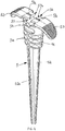
- Figures 3A and 3B show the irrigation connector arrangement 2 in isolation and Figure 4 shows the ground spike 5 alone.
- each irrigation connector arrangement comprises an irrigation connector 4 mounted to a ground spike 5 for securing the irrigation connector 4 and hence a carried supply hose in position, as schematically illustrated in Figures 1 and 2 .
- the irrigation connector 4 is arranged for movement relative to the ground spike 5, such that the irrigation connector 4 may be orientated at different orientations relative to the spike 5.
- Figure 3A the irrigation connector 4 is shown in an upright (or vertical) position whereas in Figure 3B the irrigation connector 4 is shown in a horizontal position.
- the irrigation connector 4 comprises a hose retaining portion 41 for holding the supply hose 1 as shown in Figures 1 and 2 .
- the needle connector 4 further comprises a hollow needle 6 with an open side window 61, which is arranged for projecting into a hose receiving region of the hose retaining portion 41, so as to penetrate into the interior of a supply hose 1 when located in the hose retaining portion 41.
- the irrigation connector 4 comprises a drive mechanism 45 for driving the hollow needle 6 from a retracted position, where the needle 6 does not extend into the hose receiving region, towards the extended position, shown in Figure 3B , where it can penetrate through the wall of a carried supply hose.
- the irrigation connector 4 comprises a water outlet portion 43 which comprises a sealing clamp portion 44 for connecting an outlet component 3 such as a dripper, sprinkler unit or tubing to the irrigation connector 4.
- the ground spike 5 comprises a main body portion 51 from which a spike portion 52 projects.
- the spike portion 52 is arranged for penetrating ground to secure the ground spike and items held by it.
- the spike portion 52 comprises a strengthening rib 52a.
- a pair of securing lugs 53 project from the main body 51. These lugs project from opposing sides of the main body 51 and are useful for retaining supply hose as well as for use by a user when removing the ground spike 5 from the ground.
- Rib portions 51a are also provided on the main body 51 to assist the user grip of the ground spike 5.
- the main body 51 comprises a part circular cut-out 54 which is arranged as a micro tube grip, thus allowing the ground spike 5 to secure micro tube in position.
- a groove 55 (see Figure 3A ) is provided in one side of the main body 51 which is arranged for guiding and/or gripping micro tube which is connected to an irrigation outlet component held in an irrigation outlet component mounting portion 56 of the spike.
- the ground spike 5 also comprises an attachment portion 57 for use in attaching the irrigation connector 4 of the type described above to the ground spike 5.
- the lugs 53, part circular cut-out 54, groove 55, mounting portion 56 and attachment portion 57 can each be considered as respective holding portions. These holding portions differ from one another and are arranged for holding respective different components which will be used in an overall irrigation system.
- Figures 5A-5D show examples of a ground spike 5 being used to hold different components and making use of these different holding portions.
- the lugs 53 define a space between the main body portion 51 and the respective lug 53 which acts as a supply hose receiving portion. It will be noted that this region has a mouth of a dimension which is chosen for allowing the insertion of a supply hose diameter such that the lug 53 may be located over a supply hose when the ground spike is driven into the ground.
- Figure 5B shows a ground spike 5 holding supply hose 1 in this way.
- the part circular cut-out 54 and groove 55 are arranged to have a dimension which is suitable to accept micro tube.
- the part circular cut-out 54 has a mouth of a smaller dimension than that between the lugs 53 and the main body 51.
- Figure 5A shows micro tube located and held in the part circular cut-out 54.
- Figure 5C shows an irrigation connector 4 held in the attachment portion 57 of the ground spike 5 whilst Figure 5D shows a multi-function unit M arranged as a dripper unit held in the irrigation outlet component mounting portion 56.
- the ground spike 5 comprises a pair of arms 57b which provide the attachment portion 57 for attaching an irrigation connector 4 to the spike 5.
- the arms 57b project from the main body 51 of the ground spike 5 towards one another. As such they define a first slot between the arms 57b and the main body 51 and a second slot between the arms 57b themselves.
- the arms 57b also provide a location at which a irrigation component can be attached. This is supplementary to the irrigation component mounting portion 56 provided in the side of the main body 51. In both cases a flange F (see Figure 5D ) of the irrigation component can be slid into engagement with a slot provided in the spike 5.
- the two mounting portions allow an irrigation component to be connected at respective different orientations - e.g one vertical and one horizontal.
- the irrigation connector 4 is arranged to be orientatable at different angles relative to the ground spike 5.
- the irrigation connector 4 comprises an attachment portion 47 which is arranged to be complimentary with the attachment portion 57 on the ground spike 5. These complementary attachment portions 47, 57 allow the connector 4 to be mounted on the spike 5 and the orientation of the connector 4 to be varied relative to the spike 5.
- the attachment portion 47 on the irrigation connector 4 extends part way around the retaining portion 41 so as to present a plurality of different angularly spaced attachment regions at which the attachment portion 57 of the spike 5 may be selectively located.
- the attachment portion 47 of the irrigation connector 4 comprises a runner 47 which is accepted in the slots defined by the arms 57 on the spike 5.
- the attachment portions 47, 57 comprise indexing means for indexing relative movement of the attachment portions as the orientation of the irrigation connector 4 is altered relative to the spike 5.
- the attachment portion 47 on the irrigation connector 4 comprises a series of projections and recesses 47a a nd 47b (see Figures 3A and 3B ) and the attachment portion on the spike comprises projections 57a.
- the projections on the spike 5 are arranged to ride over a respective one of the projections 47a on the irrigation 4 connector as the irrigation connector 4 is moved from one index position determined by a respective one of the recesses 47b to another.
- the runner 47 When the spike 5 is mounted on the irrigation connector 4, the runner 47 is captured in the slots defined by the arms 57.
- the runner 47 is mounted on a supporting stem 47c and projects from either side of the stem.
- the arms 57b of the attachment portion 57 on the spike wrap around the extending portions of the runner and capture the runner 47. Resilience in the arms 57b allows the indexing movement.
- the projections 57a on the spike 5 act on a face of the retaining portion 41 which is opposite the extending portions of the runner.
- the projections 57a may be omitted. This reduces the force needed to move between indexed positions.
- the multi-function unit M shown in Figure 5D comprises a body portion M1 and a nut portion M2.
- the body portion M1 has a spigot (not shown) arranged to connect to micro-tube and comprises the flange F mentioned above which can be accepted and held in a spike 5.
- the multi-function unit M is held in a first (horizontal) orientation in the spike 5.
- the flange F is held in the irrigation component mounting portion 56.
- the unit M may also be held in a second (vertical) orientation. In this case the flange F is held by the arms 57b in the above mentioned slot.
- the nut portion M2 provides the function for the unit M and can be tightened onto the body portion M1.
- the nut portion is a dripper nut portion.
- the unit may be provided with a shrubbier nut (providing a mini-sprinkler outlet) or a clamping nut to allow connection to another piece of micro tube.
- FIGS. 6A and 6B show an alternative spike 5' which is similar to that described above but has a different arrangement in the main body 51' and attachment arms 57b'.
- the part circular cut-out 54' is provided in the side of the main body 51'.
- the arms 57b' are L-shaped and project from the main body with their respective foot uppermost.
- the free ends of the L-shaped arms 57b' are shaped so as to provide a keyhole shaped slot in what is the upper surface of the spike.
- This keyhole shaped slot provides the irrigation component mounting portion 56' in this case.
- a dripper unit such as the one shown in Figure 5D may be slid into engagement with the large dimension portion of the keyhole shape slot 56'.
Landscapes
- Engineering & Computer Science (AREA)
- Life Sciences & Earth Sciences (AREA)
- General Engineering & Computer Science (AREA)
- Water Supply & Treatment (AREA)
- Environmental Sciences (AREA)
- Mechanical Engineering (AREA)
- Soil Sciences (AREA)
- Structural Engineering (AREA)
- General Life Sciences & Earth Sciences (AREA)
- Mining & Mineral Resources (AREA)
- Paleontology (AREA)
- Civil Engineering (AREA)
- Catching Or Destruction (AREA)
- Supports For Pipes And Cables (AREA)
- Nozzles (AREA)
Description
- This invention relates to irrigation system ground spikes for securing components in an irrigation system. Typically, ground spikes of the current type will be used in domestic garden irrigation systems, which are sometimes termed micro irrigation systems.
- Such systems can be useful for the consumer in providing a permanent or semi-permanent watering arrangement for use in gardens, allotments, and so on. However existing micro irrigation systems are generally difficult to set up, install and change. Typically a large number of different products/components are required in order to set up even a relatively simple micro irrigation system and time consuming and fiddly operations are required by a user in installing such a system.
- It would be desirable to provide an irrigation system or parts for use in an irrigation system, which can provide easy and safe setup as well an effective resulting system.
-
EP 1490617 describes a ground spike which is arranged for holding different components and has different holding portions for holding respective different components.GB 2 366 346 A - According to one aspect of the invention there is provided an irrigation system ground spike according to claim 1.
- Thus the ground spike may be multi-functional which can enhance ease of use for the user in setting up an irrigation system and reduce the number of components that need to be manufactured.
- One of the holding portions may be arranged for holding tube or hose of a first diameter and another of the holding portions may be arranged for holding tube or hose of a second diameter.
- One of the holding portions may comprise a micro tube grip.
- One of the holding portions may comprise an irrigation connector attachment portion for attaching an irrigation connector to the ground spike. The irrigation connector will typically be arranged to allow connection of micro tube and/or other irrigation outlet components such as sprinkler units or dripper units to a supply hose.
- One of the holding portions may comprise an irrigation outlet component mounting portion for mounting an irrigation outlet component on the ground spike. The irrigation outlet component may, for example, comprise a sprinkler unit or a dripper unit.
- The ground spike may comprise any one of, or any combination of: a micro tube grip, a supply hose securing lug, an irrigation connector attachment portion for attaching an irrigation connector to the ground spike, an irrigation outlet component mounting portion for mounting an irrigation outlet component on the ground spike.
- The main body portion and spike portion may be of a single piece of material.
- The ground spike may be of a single piece of material.
- One of the holding portions may comprise a part circular cut out in the main body portion, which cut out is for holding a micro tube. As such the cut out can be considered a mirco tube grip.
- Where the ground spike comprises said part circular cut out, the part circular cut out may define a tube receiving region having a mouth through which tube may be introduced whilst the securing lug and main body may define a hose receiving region having a mouth through which hose may be introduced, wherein the mouth of the tube receiving region is smaller than the mouth of the hose receiving region.
- The ground spike may comprise a pair of opposing arms extending from the main body portion. The irrigation connector attachment portion and/or the irrigation outlet component mounting portion may comprise the opposing arms. The arms may define a slot for receiving an attachment portion of an irrigation connector. The arms may define a receiving location for accepting an irrigation outlet component.
- The arms may be generally L-shaped in cross section.
- The arms may define a first slot between the pair of arms on the one hand and the main body portion in the other hand. The arms may define a second slot transverse to the first slot and between the arms themselves. The second slot may be a keyhole shaped slot. In such a case, a larger dimensioned portion of the keyhole shaped slot may provide the receiving location. An irrigation outlet component may be slid into engagement with the arms. The arms may be resilient.
- A groove may be provided in the main body portion to act as a guide for micro tube.
- Grips may be provided on the main body portion to assist a user in removing the ground spike from the ground.
- The spike portion may comprise at least one strengthening longitudinal rib.
- According to another aspect of the invention there is provided an irrigation connector arrangement comprising ground spike, as defined above, and an irrigation connector attached to the ground spike.
- The irrigation connector may be arranged for tapping into a water supply hose and may comprise a retaining portion for holding a supply hose in a hose receiving region of the retaining portion and a hollow needle extending into the hose receiving region of the retaining portion for penetrating a supply hose held in the retaining portion to create a fluid communication path between an interior of the needle and an interior of a supply hose held in the retaining portion.
- The needle may be mounted for movement relative to the retaining portion between a retracted position and an extended position in which the needle extends into the hose receiving region.
- The connector may comprise a needle drive arrangement for driving the needle towards the extended position.
- The connector may further comprise a water outlet portion for accepting water from the interior of the needle and passing water out of the connector. The water outlet portion may comprise a sealing clamp arrangement for connecting an outlet component to the irrigation connector.
- The irrigation connector and spike may comprise complementary attachment portions allowing the connector to be mounted on the spike and the orientation of the connector to be varied relative to the spike.
- In some embodiments the attachment portion on the connector extends at least part way around the retaining portion so as to present a plurality of different angularly spaced attachment regions at which the attachment portion of the spike may be selectively located.
- The attachment portion on the connector may comprise a runner accepted in the slot in the attachment portion on the spike.
- The complementary attachment portions may comprise indexing means for indexing relative movement of the attachment portions as the orientation of the connector is altered relative to the spike.
- The indexing means may comprise a series of projections and recesses on the attachment portion provided on the connector, and a projection on the attachment portion on the spike, which is arranged to ride over a respective one of the projections on the connector as the connector is moved from one indexed position, determined by a respective recess to another.
- According to another aspect of the invention there is provided an irrigation system comprising at least two ground spikes as defined above, and at least two of: a length of supply hose, a length of micro tube, an irrigation connector, and an irrigation outlet component, wherein each of said two ground spikes holds a respective different one of said at least two of: a length of supply hose, a length of micro tube, an irrigation connector, and an irrigation outlet component.
- Embodiments of the present invention will now be described, by way of example only, with reference to the accompanying drawings, in which:
-
Figure 1 schematically shows a micro irrigation system; -
Figure 2 schematically shows one irrigation connector arrangement mounted on a supply hose, which together form part of the irrigation system shown inFigure 1 ; -
Figures 3A and 3B schematically show a needle connector arrangement of the type used in the irrigation system ofFigure 1 , withFigure 3A showing an irrigation connector of the irrigation connector arrangement in a vertical orientation andFigure 3B showing the irrigation connector in a horizontal orientation; -
Figure 4 shows a ground spike which forms part of the irrigation connector arrangement shown inFigures 3A and 3B ; -
Figures 5A to 5D show the ground spike ofFigures 4A and 4B being used in a number of different ways -Figure 5A shows the spike holding micro tube,Figure 5B shows the spike holding supply hose,Figure 5C shows the spike holding an irrigation connector andFigure 5D shows the spike holding a dripper unit; andFigures 6A and 6B show an alternative ground spike. -
Figure 1 schematically shows a micro irrigation system of the type which may be used for watering plants in, for example, a domestic garden or other similar situation. The micro irrigation system comprises a supply hose 1 which is connected to a water supply (not shown). Mounted on the supply hose 1 are a plurality ofirrigation connector arrangements 2 which serve to make a connection to the water supply hose such that water flowing in the water supply hose can be tapped off by theirrigation connector arrangement 2 and allowed to leave the supply hose 1 for watering purposes. Eachirrigation connector arrangement 2 may have connected to it a respectivewater outlet component 3 such as, for example, a further length of hose or tubing, a dripper unit, a sprinkler unit, or so on. Eachirrigation connector arrangement 2 comprises anirrigation connector 4 andground spike 5 for securing it in place. The irrigation system comprisesfurther ground spikes 5 for directly securing other components such as the supply hose 1, micro tube, dripper units, sprinkler units and so on. - In such an irrigation system, the water supply hose 1 and
outlet components 3 may be standard commercially available products. For example, the water supply hose 1 may be a length of standard garden hose. -
Figure 2 shows one of the irrigation connector arrangements ofFigure 1 in more detail whilst mounted on the water supply hose 1. On the other hand,Figures 3A and 3B show theirrigation connector arrangement 2 in isolation andFigure 4 shows theground spike 5 alone. - As mentioned above, each irrigation connector arrangement comprises an
irrigation connector 4 mounted to aground spike 5 for securing theirrigation connector 4 and hence a carried supply hose in position, as schematically illustrated inFigures 1 and2 . In the present embodiment theirrigation connector 4 is arranged for movement relative to theground spike 5, such that theirrigation connector 4 may be orientated at different orientations relative to thespike 5. For example, inFigure 3A theirrigation connector 4 is shown in an upright (or vertical) position whereas inFigure 3B theirrigation connector 4 is shown in a horizontal position. - The
irrigation connector 4 comprises ahose retaining portion 41 for holding the supply hose 1 as shown inFigures 1 and2 . Theneedle connector 4 further comprises a hollow needle 6 with anopen side window 61, which is arranged for projecting into a hose receiving region of thehose retaining portion 41, so as to penetrate into the interior of a supply hose 1 when located in thehose retaining portion 41. - The
irrigation connector 4 comprises adrive mechanism 45 for driving the hollow needle 6 from a retracted position, where the needle 6 does not extend into the hose receiving region, towards the extended position, shown inFigure 3B , where it can penetrate through the wall of a carried supply hose. - The
irrigation connector 4 comprises awater outlet portion 43 which comprises a sealingclamp portion 44 for connecting anoutlet component 3 such as a dripper, sprinkler unit or tubing to theirrigation connector 4. - When the hollow needle 6 penetrates into the interior of a carried supply hose 1, there is a fluid communication path between the interior of the supply hose 1 and the interior of the
irrigation connector 4 and any water outlet component 3 (seeFigures 1 and2 ) held in theirrigation connector 4. - Referring particularly to
Figure 4 , theground spike 5 comprises amain body portion 51 from which aspike portion 52 projects. Thespike portion 52 is arranged for penetrating ground to secure the ground spike and items held by it. Thespike portion 52 comprises a strengtheningrib 52a. A pair of securinglugs 53 project from themain body 51. These lugs project from opposing sides of themain body 51 and are useful for retaining supply hose as well as for use by a user when removing the ground spike 5 from the ground.Rib portions 51a are also provided on themain body 51 to assist the user grip of theground spike 5. - The
main body 51 comprises a part circular cut-out 54 which is arranged as a micro tube grip, thus allowing theground spike 5 to secure micro tube in position. A groove 55 (seeFigure 3A ) is provided in one side of themain body 51 which is arranged for guiding and/or gripping micro tube which is connected to an irrigation outlet component held in an irrigation outletcomponent mounting portion 56 of the spike. Theground spike 5 also comprises anattachment portion 57 for use in attaching theirrigation connector 4 of the type described above to theground spike 5. - The
lugs 53, part circular cut-out 54,groove 55, mountingportion 56 andattachment portion 57 can each be considered as respective holding portions. These holding portions differ from one another and are arranged for holding respective different components which will be used in an overall irrigation system.Figures 5A-5D show examples of aground spike 5 being used to hold different components and making use of these different holding portions. - The
lugs 53 define a space between themain body portion 51 and therespective lug 53 which acts as a supply hose receiving portion. It will be noted that this region has a mouth of a dimension which is chosen for allowing the insertion of a supply hose diameter such that thelug 53 may be located over a supply hose when the ground spike is driven into the ground.Figure 5B shows aground spike 5 holding supply hose 1 in this way. - On the other hand, the part circular cut-out 54 and
groove 55 are arranged to have a dimension which is suitable to accept micro tube. Thus the part circular cut-out 54 has a mouth of a smaller dimension than that between thelugs 53 and themain body 51.Figure 5A shows micro tube located and held in the part circular cut-out 54. -
Figure 5C shows anirrigation connector 4 held in theattachment portion 57 of theground spike 5 whilstFigure 5D shows a multi-function unit M arranged as a dripper unit held in the irrigation outletcomponent mounting portion 56. - The
ground spike 5 comprises a pair ofarms 57b which provide theattachment portion 57 for attaching anirrigation connector 4 to thespike 5. Thearms 57b project from themain body 51 of theground spike 5 towards one another. As such they define a first slot between thearms 57b and themain body 51 and a second slot between thearms 57b themselves. Thearms 57b also provide a location at which a irrigation component can be attached. This is supplementary to the irrigationcomponent mounting portion 56 provided in the side of themain body 51. In both cases a flange F (seeFigure 5D ) of the irrigation component can be slid into engagement with a slot provided in thespike 5. The two mounting portions allow an irrigation component to be connected at respective different orientations - e.g one vertical and one horizontal. - As mentioned above, the
irrigation connector 4 is arranged to be orientatable at different angles relative to theground spike 5. Theirrigation connector 4 comprises anattachment portion 47 which is arranged to be complimentary with theattachment portion 57 on theground spike 5. Thesecomplementary attachment portions connector 4 to be mounted on thespike 5 and the orientation of theconnector 4 to be varied relative to thespike 5. Theattachment portion 47 on theirrigation connector 4 extends part way around the retainingportion 41 so as to present a plurality of different angularly spaced attachment regions at which theattachment portion 57 of thespike 5 may be selectively located. - The
attachment portion 47 of theirrigation connector 4 comprises arunner 47 which is accepted in the slots defined by thearms 57 on thespike 5. Theattachment portions irrigation connector 4 is altered relative to thespike 5. Theattachment portion 47 on theirrigation connector 4 comprises a series of projections and recesses 47a a nd 47b (seeFigures 3A and 3B ) and the attachment portion on the spike comprisesprojections 57a. The projections on thespike 5 are arranged to ride over a respective one of theprojections 47a on theirrigation 4 connector as theirrigation connector 4 is moved from one index position determined by a respective one of the recesses 47b to another. When thespike 5 is mounted on theirrigation connector 4, therunner 47 is captured in the slots defined by thearms 57. Therunner 47 is mounted on a supporting stem 47c and projects from either side of the stem. Thearms 57b of theattachment portion 57 on the spike wrap around the extending portions of the runner and capture therunner 47. Resilience in thearms 57b allows the indexing movement. Theprojections 57a on thespike 5 act on a face of the retainingportion 41 which is opposite the extending portions of the runner. - In an alternative the
projections 57a may be omitted. This reduces the force needed to move between indexed positions. - The multi-function unit M shown in
Figure 5D comprises a body portion M1 and a nut portion M2. The body portion M1 has a spigot (not shown) arranged to connect to micro-tube and comprises the flange F mentioned above which can be accepted and held in aspike 5. InFigure 5D the multi-function unit M is held in a first (horizontal) orientation in thespike 5. In this case the flange F is held in the irrigationcomponent mounting portion 56. The unit M may also be held in a second (vertical) orientation. In this case the flange F is held by thearms 57b in the above mentioned slot. The nut portion M2 provides the function for the unit M and can be tightened onto the body portion M1. InFigure 5D the nut portion is a dripper nut portion. In alternatives the unit may be provided with a shrubbier nut (providing a mini-sprinkler outlet) or a clamping nut to allow connection to another piece of micro tube. -
Figures 6A and 6B show an alternative spike 5' which is similar to that described above but has a different arrangement in the main body 51' andattachment arms 57b'. - In this case, the part circular cut-out 54' is provided in the side of the main body 51'. Further the
arms 57b' are L-shaped and project from the main body with their respective foot uppermost. As best seen inFigure 6B , the free ends of the L-shapedarms 57b' are shaped so as to provide a keyhole shaped slot in what is the upper surface of the spike. This keyhole shaped slot provides the irrigation component mounting portion 56' in this case. A dripper unit such as the one shown inFigure 5D may be slid into engagement with the large dimension portion of the keyhole shape slot 56'.
Claims (15)
- An irrigation system ground spike (5) for securing at least one component of an irrigation system, the ground spike comprising a spike portion (52) for penetrating soil to hold the ground spike (5) in position and at least two holding portions (53, 54, 55, 56, 57), each holding portion for holding a respective component of an irrigation system,wherein the ground spike comprises a main body (51) from which the spike portion projects (52), one of the holding portions comprises a supply hose securing lug (53) which projects from the main body portion, the ground spike (5) comprises a second supply hose securing lug (53) such that there is a pair of hose securing lugs (53) each projecting from a respective opposite side of the main body (51), the lugs (53) being useful for retaining supply hose as well as for user when removing the ground spike from the ground, and each lug (53) defines a space between the main body portion (51) and the respective lug (53) which acts as a supply hose receiving portion, characterized in thata first of the two holding portions differs from a second of the two portions so facilitating use of the spike for selectively securing respective different components.
- An irrigation system ground spike according to claim 1 in which one of the holding portions (53, 54, 55) is arranged for holding tube or hose of a first diameter and another of the holding portions (53, 54, 55) is arranged for holding tube or hose of a second diameter.
- An irrigation system ground spike according to claim 1 or claim 2 in which the ground spike (5) comprises any one of, or any combination of: a micro tube grip (54), an irrigation connector attachment portion (57) for attaching an irrigation connector to the ground spike, an irrigation outlet component mounting portion (50) for mounting an irrigation outlet component on the ground spike.
- An irrigation system ground spike according to any preceding claim in which the ground spike (5) is of a single piece of material.
- An irrigation system ground spike according to any preceding claim in which one of the holding portions comprises a part circular cut out (54) in the main body portion (51), which cut out is for holding a micro tube.
- An irrigation system ground spike according to claim 5 in which the part circular cut out (54) defines a tube receiving region having a mouth through which the tube may be introduced whilst the securing lug (53) and main body (51) define a hose receiving region having a mouth through which the hose may be introduced, wherein the mouth of the tube receiving region is smaller than the mouth of the hose receiving region.
- An irrigation system ground spike according to any preceding claim in which the ground spike comprises a pair of opposing arms (57b) extending from the main body portion, wherein an irrigation connector attachment portion (57) and/or an irrigation outlet component mounting portion (56) comprise the opposing arms.
- An irrigation system ground spike according to claim 7 in which the arms (57b) define a first slot between the pair of arms on the one hand and the main body portion in the other hand.
- An irrigation system ground spike according to claim 8 in which the arms (57b) define a second slot transverse to the first slot and between the arms themselves.
- An irrigation system ground spike according to any preceding claim in which a groove (55) is provided in the main body portion (51) to act as a guide for micro tube.
- An irrigation connector arrangement comprising ground spike according to any preceding claim and an irrigation connector (4) attached to the ground spike (5).
- An irrigation connector arrangement according to claim 11 in which the irrigation connector (4) and ground spike (5) comprise complementary attachment portions (47, 57) allowing the connector to be mounted on the spike and the orientation of the connector to be varied relative to the spike.
- An irrigation connector arrangement according to claim 12 in which the attachment portion (47) on the connector extends at least part way around a retaining portion of the connector so as to present a plurality of different angularly spaced attachment regions at which the attachment portion of the spike may be selectively located.
- An irrigation connector arrangement according to claim 13 in which the complementary attachment portions (47, 57) comprise indexing means (47a, 47b) for indexing relative movement of the attachment portions as the orientation of the connector is altered relative to the spike.
- An irrigation system comprising at least two ground spikes according to any one of claims 1 to 10, and at least two of: a length of supply hose, a length of micro tube, an irrigation connector, and an irrigation outlet component, wherein each of said two ground spikes holds a respective different one of said at least two of: a length of supply hose, a length of micro tube, an irrigation connector, and an irrigation outlet component.
Priority Applications (1)
| Application Number | Priority Date | Filing Date | Title |
|---|---|---|---|
| PL16712439T PL3277075T3 (en) | 2015-04-02 | 2016-03-24 | Irrigation system ground spike |
Applications Claiming Priority (2)
| Application Number | Priority Date | Filing Date | Title |
|---|---|---|---|
| GB1505752.4A GB2536961B (en) | 2015-04-02 | 2015-04-02 | Irrigation system ground spikes |
| PCT/GB2016/050853 WO2016156817A1 (en) | 2015-04-02 | 2016-03-24 | Irrigation system ground spike |
Publications (2)
| Publication Number | Publication Date |
|---|---|
| EP3277075A1 EP3277075A1 (en) | 2018-02-07 |
| EP3277075B1 true EP3277075B1 (en) | 2021-09-22 |
Family
ID=53190143
Family Applications (1)
| Application Number | Title | Priority Date | Filing Date |
|---|---|---|---|
| EP16712439.5A Active EP3277075B1 (en) | 2015-04-02 | 2016-03-24 | Irrigation system ground spike |
Country Status (9)
| Country | Link |
|---|---|
| US (1) | US10350629B2 (en) |
| EP (1) | EP3277075B1 (en) |
| CN (1) | CN108541284B (en) |
| AU (1) | AU2016240034B2 (en) |
| ES (1) | ES2897007T3 (en) |
| GB (1) | GB2536961B (en) |
| PL (1) | PL3277075T3 (en) |
| PT (1) | PT3277075T (en) |
| WO (1) | WO2016156817A1 (en) |
Families Citing this family (7)
| Publication number | Priority date | Publication date | Assignee | Title |
|---|---|---|---|---|
| GB2536960B (en) * | 2015-04-02 | 2021-02-24 | Exel Industries Sa | Irrigation connectors |
| US10462984B1 (en) * | 2017-06-02 | 2019-11-05 | Julian Koziak | Watering system |
| US20190124909A1 (en) * | 2017-10-26 | 2019-05-02 | Sandy Schaller | Weed growth suppression device |
| DE102017129007B4 (en) * | 2017-12-06 | 2026-05-21 | Agrotop Gmbh | Device for dispensing liquids and in particular fertilizers, pesticides and the like |
| US20200068820A1 (en) * | 2018-08-30 | 2020-03-05 | Ezra Kohavi | Irrigation system |
| CN111536319A (en) * | 2020-05-28 | 2020-08-14 | 中国石化销售股份有限公司华南分公司 | Anchoring type pipeline anti-seismic protection structure |
| PL447013A1 (en) * | 2023-12-07 | 2025-06-09 | Kaniewski Tomasz Agro - Tom | Modular needle for precise irrigation |
Family Cites Families (15)
| Publication number | Priority date | Publication date | Assignee | Title |
|---|---|---|---|---|
| US3091401A (en) * | 1962-02-19 | 1963-05-28 | Rain Jet Corp | Sprinkling system |
| US3385525A (en) * | 1967-03-16 | 1968-05-28 | Arthur W. Jacobs | Lawn sprinkler |
| US3929288A (en) * | 1974-07-22 | 1975-12-30 | Uniflex Spa | Water line |
| US4087049A (en) * | 1975-12-15 | 1978-05-02 | Vincent Joseph Traina | Aboveground sprinkling device for sprinkling system |
| US4294470A (en) * | 1978-12-11 | 1981-10-13 | Reed Irrigation Systems Pty Ltd. | In-line tube junctions |
| US4365750A (en) * | 1980-01-09 | 1982-12-28 | Engineering Systems Corporation | Adjustable sprinkler system |
| CN87105447A (en) * | 1987-08-12 | 1988-03-09 | 石河子工业技术开发研究中心 | Small stream irrigating system with plastic hose |
| US5172515A (en) * | 1990-10-31 | 1992-12-22 | Lapshansky Sr John F | Irrigation system and portable watering system therefor |
| GB2366346A (en) * | 2000-07-07 | 2002-03-06 | Long Wang Ching | Improved garden pipe fastener |
| DE10214681B4 (en) * | 2002-03-28 | 2004-08-19 | Gardena Manufacturing Gmbh | Mounting arrangement for a pipeline network |
| US7066403B2 (en) * | 2002-11-07 | 2006-06-27 | L.R. Nelson Corporation | Sprinkling system and method |
| GB2421784A (en) * | 2005-01-04 | 2006-07-05 | Feng-Nien Lee | Solar Powered Light with Water sprayer |
| US7303148B2 (en) | 2005-08-12 | 2007-12-04 | Tracy L Campbell | Lawn sprinkler system |
| US7654473B2 (en) * | 2006-09-01 | 2010-02-02 | Hibberd Michael J | Flexible watering system and method for using same |
| US7871022B1 (en) * | 2007-06-14 | 2011-01-18 | Mark Franklin Plyler | Positionable mister assembly |
-
2015
- 2015-04-02 GB GB1505752.4A patent/GB2536961B/en active Active
-
2016
- 2016-03-24 ES ES16712439T patent/ES2897007T3/en active Active
- 2016-03-24 AU AU2016240034A patent/AU2016240034B2/en not_active Ceased
- 2016-03-24 PT PT16712439T patent/PT3277075T/en unknown
- 2016-03-24 CN CN201680021240.7A patent/CN108541284B/en active Active
- 2016-03-24 EP EP16712439.5A patent/EP3277075B1/en active Active
- 2016-03-24 PL PL16712439T patent/PL3277075T3/en unknown
- 2016-03-24 US US15/562,785 patent/US10350629B2/en not_active Expired - Fee Related
- 2016-03-24 WO PCT/GB2016/050853 patent/WO2016156817A1/en not_active Ceased
Also Published As
| Publication number | Publication date |
|---|---|
| PL3277075T3 (en) | 2022-01-31 |
| CN108541284B (en) | 2021-05-25 |
| US10350629B2 (en) | 2019-07-16 |
| WO2016156817A1 (en) | 2016-10-06 |
| PT3277075T (en) | 2021-10-28 |
| EP3277075A1 (en) | 2018-02-07 |
| AU2016240034A1 (en) | 2017-10-26 |
| GB201505752D0 (en) | 2015-05-20 |
| AU2016240034B2 (en) | 2020-05-21 |
| US20180281009A1 (en) | 2018-10-04 |
| CN108541284A (en) | 2018-09-14 |
| GB2536961A (en) | 2016-10-05 |
| ES2897007T3 (en) | 2022-02-28 |
| GB2536961B (en) | 2021-02-24 |
Similar Documents
| Publication | Publication Date | Title |
|---|---|---|
| US10350629B2 (en) | Irrigation system ground spike | |
| EP3277074B1 (en) | Irrigation connectors | |
| US9661807B2 (en) | Conduit with connector and assembly thereof | |
| US20140062081A1 (en) | Pipe connector | |
| US20160270308A1 (en) | Tree sap line connector and assembly | |
| KR101045854B1 (en) | Multi-layered water storage unit device for plant cultivation | |
| KR101424536B1 (en) | Apparatus for repelling birds | |
| KR200476176Y1 (en) | Automatic nozzle angle adjustment device of bangjegi | |
| US20240164264A1 (en) | Root irrigation spike apparatus | |
| CN220157245U (en) | Assembled underground infiltrating irrigation card | |
| EP3037108B1 (en) | System for the fast connection of a pipe to an outlet and the automatic closing of the outlet in the absence of the pipe | |
| GB2494749A (en) | Enteral feeding device comprising a button and connector | |
| KR200458943Y1 (en) | A vinyl house of cultivation water a hose hang pole | |
| CN114733696B (en) | Nozzle and optical fiber water curtain with same | |
| SK7752Y1 (en) | Mouldable attachment to increase the upper limit of polyurethane foam application | |
| KR20090003423U (en) | Connecting member for culvert bundle | |
| KR20120008743U (en) | Establishes a crops cultivation liquid makeup company unit respects and the fixation unit which falls. | |
| CN213777025U (en) | Buzzer installation adjustment matching structure | |
| KR20200000878U (en) | The divergent tool of drops hose for clamp | |
| KR100519976B1 (en) | A nozzle coupling pipe for a greenhouse | |
| JP4349498B1 (en) | Insertion jig for insertion tube | |
| ITTA20150001U1 (en) | PROVISIONAL VASE OF OPENINGS FOR THE LODGING OF DROPLET PIPES FOR IRRIGATION. | |
| KR20110006381U (en) | Clamping Device of trajectory Pipe cutting machine | |
| SE1451239A1 (en) | Cylindrical valve with push-turn switching mechanism |
Legal Events
| Date | Code | Title | Description |
|---|---|---|---|
| STAA | Information on the status of an ep patent application or granted ep patent |
Free format text: STATUS: THE INTERNATIONAL PUBLICATION HAS BEEN MADE |
|
| PUAI | Public reference made under article 153(3) epc to a published international application that has entered the european phase |
Free format text: ORIGINAL CODE: 0009012 |
|
| STAA | Information on the status of an ep patent application or granted ep patent |
Free format text: STATUS: REQUEST FOR EXAMINATION WAS MADE |
|
| 17P | Request for examination filed |
Effective date: 20170921 |
|
| AK | Designated contracting states |
Kind code of ref document: A1 Designated state(s): AL AT BE BG CH CY CZ DE DK EE ES FI FR GB GR HR HU IE IS IT LI LT LU LV MC MK MT NL NO PL PT RO RS SE SI SK SM TR |
|
| AX | Request for extension of the european patent |
Extension state: BA ME |
|
| DAV | Request for validation of the european patent (deleted) | ||
| DAX | Request for extension of the european patent (deleted) | ||
| RIC1 | Information provided on ipc code assigned before grant |
Ipc: B05B 15/06 20181130ALI20161012BHEP Ipc: A01G 25/02 20060101AFI20161012BHEP Ipc: F16L 3/04 20060101ALI20161012BHEP |
|
| RIC1 | Information provided on ipc code assigned before grant |
Ipc: F16L 3/04 20060101ALI20161012BHEP Ipc: A01G 25/02 20060101AFI20161012BHEP Ipc: B05B 15/06 20060101ALI20161012BHEP |
|
| RIC1 | Information provided on ipc code assigned before grant |
Ipc: F16L 3/10 20060101ALI20201202BHEP Ipc: B05B 15/658 20180101ALI20201202BHEP Ipc: B05B 15/622 20180101ALI20201202BHEP Ipc: A01G 25/02 20060101AFI20201202BHEP Ipc: F16L 3/04 20060101ALI20201202BHEP |
|
| GRAP | Despatch of communication of intention to grant a patent |
Free format text: ORIGINAL CODE: EPIDOSNIGR1 |
|
| STAA | Information on the status of an ep patent application or granted ep patent |
Free format text: STATUS: GRANT OF PATENT IS INTENDED |
|
| INTG | Intention to grant announced |
Effective date: 20210114 |
|
| RIN1 | Information on inventor provided before grant (corrected) |
Inventor name: BOUGHTON, ROBERT Inventor name: GOSSINGTON, MATT |
|
| GRAJ | Information related to disapproval of communication of intention to grant by the applicant or resumption of examination proceedings by the epo deleted |
Free format text: ORIGINAL CODE: EPIDOSDIGR1 |
|
| STAA | Information on the status of an ep patent application or granted ep patent |
Free format text: STATUS: REQUEST FOR EXAMINATION WAS MADE |
|
| GRAP | Despatch of communication of intention to grant a patent |
Free format text: ORIGINAL CODE: EPIDOSNIGR1 |
|
| STAA | Information on the status of an ep patent application or granted ep patent |
Free format text: STATUS: GRANT OF PATENT IS INTENDED |
|
| INTC | Intention to grant announced (deleted) | ||
| INTG | Intention to grant announced |
Effective date: 20210623 |
|
| GRAS | Grant fee paid |
Free format text: ORIGINAL CODE: EPIDOSNIGR3 |
|
| GRAA | (expected) grant |
Free format text: ORIGINAL CODE: 0009210 |
|
| STAA | Information on the status of an ep patent application or granted ep patent |
Free format text: STATUS: THE PATENT HAS BEEN GRANTED |
|
| AK | Designated contracting states |
Kind code of ref document: B1 Designated state(s): AL AT BE BG CH CY CZ DE DK EE ES FI FR GB GR HR HU IE IS IT LI LT LU LV MC MK MT NL NO PL PT RO RS SE SI SK SM TR |
|
| REG | Reference to a national code |
Ref country code: GB Ref legal event code: FG4D |
|
| REG | Reference to a national code |
Ref country code: IE Ref legal event code: FG4D Ref country code: NL Ref legal event code: FP |
|
| REG | Reference to a national code |
Ref country code: DE Ref legal event code: R096 Ref document number: 602016063977 Country of ref document: DE |
|
| REG | Reference to a national code |
Ref country code: CH Ref legal event code: EP Ref country code: AT Ref legal event code: REF Ref document number: 1431588 Country of ref document: AT Kind code of ref document: T Effective date: 20211015 |
|
| REG | Reference to a national code |
Ref country code: DE Ref legal event code: R081 Ref document number: 602016063977 Country of ref document: DE Owner name: SA EXEL INDUSTRIES, FR Free format text: FORMER OWNER: SA EXEL INDUSTRIES, PARIS, FR |
|
| REG | Reference to a national code |
Ref country code: PT Ref legal event code: SC4A Ref document number: 3277075 Country of ref document: PT Date of ref document: 20211028 Kind code of ref document: T Free format text: AVAILABILITY OF NATIONAL TRANSLATION Effective date: 20211021 |
|
| REG | Reference to a national code |
Ref country code: SE Ref legal event code: TRGR |
|
| REG | Reference to a national code |
Ref country code: LT Ref legal event code: MG9D |
|
| PG25 | Lapsed in a contracting state [announced via postgrant information from national office to epo] |
Ref country code: RS Free format text: LAPSE BECAUSE OF FAILURE TO SUBMIT A TRANSLATION OF THE DESCRIPTION OR TO PAY THE FEE WITHIN THE PRESCRIBED TIME-LIMIT Effective date: 20210922 Ref country code: NO Free format text: LAPSE BECAUSE OF FAILURE TO SUBMIT A TRANSLATION OF THE DESCRIPTION OR TO PAY THE FEE WITHIN THE PRESCRIBED TIME-LIMIT Effective date: 20211222 Ref country code: FI Free format text: LAPSE BECAUSE OF FAILURE TO SUBMIT A TRANSLATION OF THE DESCRIPTION OR TO PAY THE FEE WITHIN THE PRESCRIBED TIME-LIMIT Effective date: 20210922 Ref country code: HR Free format text: LAPSE BECAUSE OF FAILURE TO SUBMIT A TRANSLATION OF THE DESCRIPTION OR TO PAY THE FEE WITHIN THE PRESCRIBED TIME-LIMIT Effective date: 20210922 Ref country code: LT Free format text: LAPSE BECAUSE OF FAILURE TO SUBMIT A TRANSLATION OF THE DESCRIPTION OR TO PAY THE FEE WITHIN THE PRESCRIBED TIME-LIMIT Effective date: 20210922 Ref country code: BG Free format text: LAPSE BECAUSE OF FAILURE TO SUBMIT A TRANSLATION OF THE DESCRIPTION OR TO PAY THE FEE WITHIN THE PRESCRIBED TIME-LIMIT Effective date: 20211222 |
|
| REG | Reference to a national code |
Ref country code: AT Ref legal event code: MK05 Ref document number: 1431588 Country of ref document: AT Kind code of ref document: T Effective date: 20210922 |
|
| PG25 | Lapsed in a contracting state [announced via postgrant information from national office to epo] |
Ref country code: LV Free format text: LAPSE BECAUSE OF FAILURE TO SUBMIT A TRANSLATION OF THE DESCRIPTION OR TO PAY THE FEE WITHIN THE PRESCRIBED TIME-LIMIT Effective date: 20210922 Ref country code: GR Free format text: LAPSE BECAUSE OF FAILURE TO SUBMIT A TRANSLATION OF THE DESCRIPTION OR TO PAY THE FEE WITHIN THE PRESCRIBED TIME-LIMIT Effective date: 20211223 |
|
| REG | Reference to a national code |
Ref country code: ES Ref legal event code: FG2A Ref document number: 2897007 Country of ref document: ES Kind code of ref document: T3 Effective date: 20220228 |
|
| PG25 | Lapsed in a contracting state [announced via postgrant information from national office to epo] |
Ref country code: AT Free format text: LAPSE BECAUSE OF FAILURE TO SUBMIT A TRANSLATION OF THE DESCRIPTION OR TO PAY THE FEE WITHIN THE PRESCRIBED TIME-LIMIT Effective date: 20210922 |
|
| PG25 | Lapsed in a contracting state [announced via postgrant information from national office to epo] |
Ref country code: IS Free format text: LAPSE BECAUSE OF FAILURE TO SUBMIT A TRANSLATION OF THE DESCRIPTION OR TO PAY THE FEE WITHIN THE PRESCRIBED TIME-LIMIT Effective date: 20220122 Ref country code: SK Free format text: LAPSE BECAUSE OF FAILURE TO SUBMIT A TRANSLATION OF THE DESCRIPTION OR TO PAY THE FEE WITHIN THE PRESCRIBED TIME-LIMIT Effective date: 20210922 Ref country code: RO Free format text: LAPSE BECAUSE OF FAILURE TO SUBMIT A TRANSLATION OF THE DESCRIPTION OR TO PAY THE FEE WITHIN THE PRESCRIBED TIME-LIMIT Effective date: 20210922 Ref country code: EE Free format text: LAPSE BECAUSE OF FAILURE TO SUBMIT A TRANSLATION OF THE DESCRIPTION OR TO PAY THE FEE WITHIN THE PRESCRIBED TIME-LIMIT Effective date: 20210922 Ref country code: CZ Free format text: LAPSE BECAUSE OF FAILURE TO SUBMIT A TRANSLATION OF THE DESCRIPTION OR TO PAY THE FEE WITHIN THE PRESCRIBED TIME-LIMIT Effective date: 20210922 Ref country code: AL Free format text: LAPSE BECAUSE OF FAILURE TO SUBMIT A TRANSLATION OF THE DESCRIPTION OR TO PAY THE FEE WITHIN THE PRESCRIBED TIME-LIMIT Effective date: 20210922 |
|
| REG | Reference to a national code |
Ref country code: DE Ref legal event code: R097 Ref document number: 602016063977 Country of ref document: DE |
|
| PG25 | Lapsed in a contracting state [announced via postgrant information from national office to epo] |
Ref country code: DK Free format text: LAPSE BECAUSE OF FAILURE TO SUBMIT A TRANSLATION OF THE DESCRIPTION OR TO PAY THE FEE WITHIN THE PRESCRIBED TIME-LIMIT Effective date: 20210922 |
|
| PLBE | No opposition filed within time limit |
Free format text: ORIGINAL CODE: 0009261 |
|
| STAA | Information on the status of an ep patent application or granted ep patent |
Free format text: STATUS: NO OPPOSITION FILED WITHIN TIME LIMIT |
|
| 26N | No opposition filed |
Effective date: 20220623 |
|
| PG25 | Lapsed in a contracting state [announced via postgrant information from national office to epo] |
Ref country code: MC Free format text: LAPSE BECAUSE OF FAILURE TO SUBMIT A TRANSLATION OF THE DESCRIPTION OR TO PAY THE FEE WITHIN THE PRESCRIBED TIME-LIMIT Effective date: 20210922 |
|
| REG | Reference to a national code |
Ref country code: CH Ref legal event code: PL |
|
| PG25 | Lapsed in a contracting state [announced via postgrant information from national office to epo] |
Ref country code: SI Free format text: LAPSE BECAUSE OF FAILURE TO SUBMIT A TRANSLATION OF THE DESCRIPTION OR TO PAY THE FEE WITHIN THE PRESCRIBED TIME-LIMIT Effective date: 20210922 |
|
| PG25 | Lapsed in a contracting state [announced via postgrant information from national office to epo] |
Ref country code: LU Free format text: LAPSE BECAUSE OF NON-PAYMENT OF DUE FEES Effective date: 20220324 Ref country code: LI Free format text: LAPSE BECAUSE OF NON-PAYMENT OF DUE FEES Effective date: 20220331 Ref country code: IE Free format text: LAPSE BECAUSE OF NON-PAYMENT OF DUE FEES Effective date: 20220324 Ref country code: CH Free format text: LAPSE BECAUSE OF NON-PAYMENT OF DUE FEES Effective date: 20220331 |
|
| PG25 | Lapsed in a contracting state [announced via postgrant information from national office to epo] |
Ref country code: HU Free format text: LAPSE BECAUSE OF FAILURE TO SUBMIT A TRANSLATION OF THE DESCRIPTION OR TO PAY THE FEE WITHIN THE PRESCRIBED TIME-LIMIT; INVALID AB INITIO Effective date: 20160324 |
|
| PG25 | Lapsed in a contracting state [announced via postgrant information from national office to epo] |
Ref country code: SM Free format text: LAPSE BECAUSE OF FAILURE TO SUBMIT A TRANSLATION OF THE DESCRIPTION OR TO PAY THE FEE WITHIN THE PRESCRIBED TIME-LIMIT Effective date: 20210922 Ref country code: MK Free format text: LAPSE BECAUSE OF FAILURE TO SUBMIT A TRANSLATION OF THE DESCRIPTION OR TO PAY THE FEE WITHIN THE PRESCRIBED TIME-LIMIT Effective date: 20210922 Ref country code: CY Free format text: LAPSE BECAUSE OF FAILURE TO SUBMIT A TRANSLATION OF THE DESCRIPTION OR TO PAY THE FEE WITHIN THE PRESCRIBED TIME-LIMIT Effective date: 20210922 |
|
| PG25 | Lapsed in a contracting state [announced via postgrant information from national office to epo] |
Ref country code: MT Free format text: LAPSE BECAUSE OF FAILURE TO SUBMIT A TRANSLATION OF THE DESCRIPTION OR TO PAY THE FEE WITHIN THE PRESCRIBED TIME-LIMIT Effective date: 20210922 |
|
| PGFP | Annual fee paid to national office [announced via postgrant information from national office to epo] |
Ref country code: ES Payment date: 20250410 Year of fee payment: 10 |
|
| PG25 | Lapsed in a contracting state [announced via postgrant information from national office to epo] |
Ref country code: TR Free format text: LAPSE BECAUSE OF FAILURE TO SUBMIT A TRANSLATION OF THE DESCRIPTION OR TO PAY THE FEE WITHIN THE PRESCRIBED TIME-LIMIT Effective date: 20210922 |
|
| PGFP | Annual fee paid to national office [announced via postgrant information from national office to epo] |
Ref country code: NL Payment date: 20260226 Year of fee payment: 11 |
|
| PGFP | Annual fee paid to national office [announced via postgrant information from national office to epo] |
Ref country code: SE Payment date: 20260320 Year of fee payment: 11 |
|
| PGFP | Annual fee paid to national office [announced via postgrant information from national office to epo] |
Ref country code: GB Payment date: 20260323 Year of fee payment: 11 |
|
| PGFP | Annual fee paid to national office [announced via postgrant information from national office to epo] |
Ref country code: DE Payment date: 20260313 Year of fee payment: 11 |
|
| PGFP | Annual fee paid to national office [announced via postgrant information from national office to epo] |
Ref country code: BE Payment date: 20260324 Year of fee payment: 11 Ref country code: IT Payment date: 20260309 Year of fee payment: 11 |
|
| PGFP | Annual fee paid to national office [announced via postgrant information from national office to epo] |
Ref country code: FR Payment date: 20260330 Year of fee payment: 11 |
|
| PGFP | Annual fee paid to national office [announced via postgrant information from national office to epo] |
Ref country code: PT Payment date: 20260220 Year of fee payment: 11 |
|
| PGFP | Annual fee paid to national office [announced via postgrant information from national office to epo] |
Ref country code: PL Payment date: 20260223 Year of fee payment: 11 |