EP3277074B1 - Irrigation connectors - Google Patents
Irrigation connectors Download PDFInfo
- Publication number
- EP3277074B1 EP3277074B1 EP16712436.1A EP16712436A EP3277074B1 EP 3277074 B1 EP3277074 B1 EP 3277074B1 EP 16712436 A EP16712436 A EP 16712436A EP 3277074 B1 EP3277074 B1 EP 3277074B1
- Authority
- EP
- European Patent Office
- Prior art keywords
- needle
- connector
- irrigation
- irrigation connector
- hose
- Prior art date
- Legal status (The legal status is an assumption and is not a legal conclusion. Google has not performed a legal analysis and makes no representation as to the accuracy of the status listed.)
- Active
Links
Images





Classifications
-
- A—HUMAN NECESSITIES
- A01—AGRICULTURE; FORESTRY; ANIMAL HUSBANDRY; HUNTING; TRAPPING; FISHING
- A01G—HORTICULTURE; CULTIVATION OF VEGETABLES, FLOWERS, RICE, FRUIT, VINES, HOPS OR SEAWEED; FORESTRY; WATERING
- A01G25/00—Watering gardens, fields, sports grounds or the like
- A01G25/02—Watering arrangements located above the soil which make use of perforated pipe-lines or pipe-lines with dispensing fittings, e.g. for drip irrigation
- A01G25/023—Dispensing fittings for drip irrigation, e.g. drippers
-
- A—HUMAN NECESSITIES
- A01—AGRICULTURE; FORESTRY; ANIMAL HUSBANDRY; HUNTING; TRAPPING; FISHING
- A01G—HORTICULTURE; CULTIVATION OF VEGETABLES, FLOWERS, RICE, FRUIT, VINES, HOPS OR SEAWEED; FORESTRY; WATERING
- A01G25/00—Watering gardens, fields, sports grounds or the like
- A01G25/02—Watering arrangements located above the soil which make use of perforated pipe-lines or pipe-lines with dispensing fittings, e.g. for drip irrigation
-
- F—MECHANICAL ENGINEERING; LIGHTING; HEATING; WEAPONS; BLASTING
- F16—ENGINEERING ELEMENTS AND UNITS; GENERAL MEASURES FOR PRODUCING AND MAINTAINING EFFECTIVE FUNCTIONING OF MACHINES OR INSTALLATIONS; THERMAL INSULATION IN GENERAL
- F16L—PIPES; JOINTS OR FITTINGS FOR PIPES; SUPPORTS FOR PIPES, CABLES OR PROTECTIVE TUBING; MEANS FOR THERMAL INSULATION IN GENERAL
- F16L41/00—Branching pipes; Joining pipes to walls
- F16L41/04—Tapping pipe walls, i.e. making connections through the walls of pipes while they are carrying fluids; Fittings therefor
- F16L41/06—Tapping pipe walls, i.e. making connections through the walls of pipes while they are carrying fluids; Fittings therefor making use of attaching means embracing the pipe
- F16L41/065—Tapping pipe walls, i.e. making connections through the walls of pipes while they are carrying fluids; Fittings therefor making use of attaching means embracing the pipe without removal of material
-
- Y—GENERAL TAGGING OF NEW TECHNOLOGICAL DEVELOPMENTS; GENERAL TAGGING OF CROSS-SECTIONAL TECHNOLOGIES SPANNING OVER SEVERAL SECTIONS OF THE IPC; TECHNICAL SUBJECTS COVERED BY FORMER USPC CROSS-REFERENCE ART COLLECTIONS [XRACs] AND DIGESTS
- Y10—TECHNICAL SUBJECTS COVERED BY FORMER USPC
- Y10T—TECHNICAL SUBJECTS COVERED BY FORMER US CLASSIFICATION
- Y10T137/00—Fluid handling
- Y10T137/598—With repair, tapping, assembly, or disassembly means
- Y10T137/612—Tapping a pipe, keg, or apertured tank under pressure
- Y10T137/6123—With aperture forming means
Definitions
- This invention relates to irrigation connectors for use in domestic garden irrigation systems, sometimes termed micro irrigation systems.
- Such systems can be useful for the consumer in providing a permanent or semi-permanent watering arrangement for use in gardens, allotments, and so on.
- micro irrigation systems are generally difficult to set up, install and change.
- a large number of different products/components are required in order to set up even a relatively simple micro-irrigation system, and time consuming and fiddly operations are required by a user in installing such a system.
- US2004/0089738 describes a sprinkling system having a two part connector for tapping into a supply hose. One part receives a hose loosely and the second part carries a piercing element. The two parts can be forced together simultaneously capturing the hose and piercing the hose.
- US 6986532 describes a saddle tee and tap for an irrigation system. This is a two part device, the saddle tee which comprises a base and clamp for engaging the irrigation line and a tap with a pointed end that screws into the saddle tee to penetrate the irrigation line.
- US 5105844 describes a two part branch forming attachment.
- One part is a snap on saddle for installing on a plastic pipe.
- a second part is a screw-in coupling cutter that engages with the saddle to cut through the piping to form a leak-proof connection.
- an irrigation connector for tapping into a water supply hose
- the connector comprising a retaining portion for holding a supply hose in a hose receiving region of the retaining portion and a hollow needle mounted for movement relative to the retaining portion between a retracted position in which the distal end of the needle is concealed and an extended position in which the needle extends into the hose receiving region for penetrating a supply hose held in the retaining portion to create a fluid communication path between an interior of the needle and an interior of a supply hose held in the retaining portion, wherein the hose receiving region is bounded by an encircling hose supporting surface and the retaining portion comprises a door portion moveable between a closed position and an open position which creates an opening in the hose supporting surface for allowing introduction and removal of a length of supply hose wherein the irrigation connector further comprises a needle drive arrangement for driving the needle towards the extended position, a needle housing portion for housing the needle in the retracted position,
- the whole needle When in the retracted position, the whole needle may be outside of the hose receiving region.
- the connector may comprise a needle holder for holding the needle.
- the connector may comprise a needle guide portion for guiding the needle between the retracted position and the extended position.
- the needle housing portion may be held in a fixed relation to the retaining portion
- the needle housing portion may comprise the needle guide portion.
- the needle housing portion and drive collar may have respective corresponding camming portions arranged so that a rotational movement of the drive collar relative to the housing portion causes axial movement of the needle between the retracted position and the extended position.
- the corresponding camming portions may comprise a twin start helix provided on one of the housing portion and the drive collar and respective follower projections on the other of the housing portion and the drive collar.
- the needle housing portion and drive collar may have respective corresponding detent portions for resisting movement of the drive collar relative to the housing portion, when the needle is in the extended position, which movement would serve to retract the needle.
- At least a portion of the needle housing portion may be of a different colour than the retaining portion and/or drive collar to help provide a visual indication of when the needle is not in the fully extended position by virtue of drive collar being in such a position as to expose said different colour portion.
- the retaining portion and needle housing portion may be a two shot injection moulded plastics component.
- the plastics material used in each "shot” may be different than the other to provide the difference in colour mentioned above.
- the retaining portion can be considered to have an axis defined by the axis of the encircling hose supporting surface. This axis will generally be aligned with an axis of supply hose which is held in the retaining portion.
- the hose supporting surface may be generally cylindrical.
- the needle may be arranged to pass through the hose supporting surface when in the extended position. In the retracted position, the needle may be disposed so that no part of the needle projects beyond the hose supporting surface.
- the needle extends in a generally radial direction relative to the axis of the retaining portion.
- the drive mechanism is arranged so that whilst axial drive is transferred to the needle, the drive collar is arranged to rotate freely relative to the needle.
- the connector may comprise a water outlet portion for accepting water from the interior of the needle and passing water out of the connector.
- the water outlet portion may comprise the needle holder.
- the drive mechanism may be arranged so that whilst axial drive is transferred to the needle, the drive collar is arranged to rotate freely relative to the water outlet portion.
- the water outlet portion may be keyed with the retaining portion to resist relative rotation between the retaining portion and the water outlet portion. This can further assist in avoiding rotation of the water outlet portion when the drive collar is operated.
- keying may be provided between the needle holder and the needle housing portion with relative rotation thereby resisted but relative axial movement allowed.
- At least one interengaging rib and groove pair may be provided for keying the needle holder with the needle housing portion.
- the connector may comprise a releasable safety lock for selectively blocking movement of the needle from the retracted to the extended position.
- the safety lock comprises a moveable plate having a needle blocking portion and including an aperture through which the needle may pass, the moveable plate being moveable between a first, blocking, position where the needle blocking portion blocks movement of the needle towards the extended position and a second position where the needle can pass through the aperture.
- the moveable plate may be biased towards the blocking position.
- the moveable plate may comprise a spring portion for providing said bias.
- the blocking portion and the spring portion may be of a single piece of material.
- the safety lock may be arranged so that presence of the needle in the aperture when the needle is in the extended position is sufficient to hold the plate in the second position against the biasing action.
- the connector may be arranged to block opening of the door portion when the needle is in the extended position.
- the needle drive arrangement may be arranged to block opening of the door portion when the needle is in the extended position.
- the drive collar may be arranged to block opening of the door portion when the drive collar is in a position corresponding to the needle being in the extended position.
- the door portion may be arranged to latch with the remainder of the retaining portion when in the closed position and the drive collar may block unlatching of the door portion when the drive collar is in a position corresponding to the needle being in the extended position.
- the water outlet portion may comprise a sealing clamp arrangement for connecting an outlet component to the irrigation connector.
- the outlet component may comprise irrigation hose or tubing, a sprinkler unit, a dripper unit or so on.
- the sealing clamp arrangement may comprise a tubular sealing element having an internal surface for sealing against an inserted outlet component, a seat portion receiving the tubular sealing element and comprising a plurality of resilient finger portions for acting on an external surface of the sealing element and a clamping nut for driving the resilient finger portions inwardly towards the axis of the sealing element as the clamping nut is tightened onto the seat portion to compress the sealing element into contact with an inserted outlet component.
- the sealing clamp can allow sealing connection to tubing or hose as the outlet component if the user desires or similarly allow sealing connection to a dripper unit or sprinkler unit if the user desires.
- the irrigation connector can allow connection of tubing to the supply hose or connection of say a dripper directly to the supply hose.
- an irrigation connector arrangement comprising an irrigation connector, as defined in any one of the aspects and optional features above, and a ground spike for securing the needle connector in position.
- the irrigation connector and spike may comprise complementary attachment portions allowing the connector to be mounted on the spike and the orientation of the connector to be varied relative to the spike.
- the attachment portion on the connector extends at least part way around the retaining portion so as to present a plurality of different angularly spaced attachment regions at which the attachment portion of the spike may be selectively located.
- the attachment portion on the connector may comprise a runner accepted in a slot in the attachment portion on the spike.
- the complementary attachment portions may comprise indexing means for indexing relative movement of the attachment portions as the orientation of the connector is altered relative to the spike.
- the indexing means may comprise a series of projections and recesses on the attachment portion provided on the connector, and a projection on the attachment portion on the spike, which is arranged to ride over a respective one of the projections on the connector as the connector is moved from one indexed position, determined by a respective recess to another.
- an irrigation connector kit comprising an irrigation connector, as defined in any one of the aspects and optional features above, and at least two outlet components, each arranged for selective mounting in the outlet portion, one of the outlet components being hose or tubing and another being a dripper unit or a sprinkler unit.
- an irrigation system comprising a supply hose, at least two irrigation connectors as defined in any one of the aspects and optional features above, each irrigation connector being mounted on the supply hose with the supply hose held in the retaining portion and a fluid communication path created between an interior of the needle and an interior of the supply hose, wherein hose or tubing is held in the water outlet portion of one of the irrigation connectors and a dripper unit or sprinkler unit is held in the water outlet portion of another of the irrigation connectors.
- FIG. 1 schematically shows a micro irrigation system of the type which may be used for watering plants in, for example, a domestic garden or other similar situation.
- the micro irrigation system comprises a supply hose 1 which is connected to a water supply (not shown).
- a water supply (not shown).
- Mounted on the supply hose 1 are a plurality of irrigation connector arrangements 2 which serve to make a connection to the water supply hose such that water flowing in the water supply hose can be tapped off by the irrigation connector arrangement 2 and allowed to leave the supply hose 1 for watering purposes.
- Each irrigation connector arrangement 2 may have connected to it a respective water outlet component 3, such as for example a further length of hose or tubing, a dripper unit, a sprinkler unit, or so on.
- the water supply hose 1 and outlet components 3 may be standard commercially available products.
- the water supply hose 1 may be a length of standard garden hose.
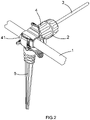
- Figure 2 shows one of the irrigation connector arrangements of Figure 1 in more detail whilst mounted on the water supply hose 1.
- Figures 3A and 3B show the irrigation connector arrangement in isolation.
- the irrigation connector arrangement comprises irrigation connector 4 mounted to a ground spike 5 for securing the irrigation connector 4 and hence a carried supply hose in position as schematically illustrated in Figures 1 and 2 .
- the irrigation connector 4 is arranged for movement relative to the ground spike 5, such that the irrigation connector 4 may be orientated at different orientations relative to the spike 5.
- Figure 3A the irrigation connector 4 is shown in an upright (or vertical) position whereas in Figure 3B the irrigation connector 4 is shown in a horizontal position.
- the irrigation connector 4 comprises a hose retaining portion 41 for holding the supply hose 1 as shown in Figures 1 and 2 .
- the needle connector 4 further comprises a hollow needle 6 with an open side window 61, which is arranged for projecting into a hose receiving region of the hose retaining portion 41, so as to penetrate into the interior of a supply hose 1 when located in the hose retaining portion 41.
- the irrigation connector 4 comprises a drive mechanism for driving the hollow needle 6 from a retracted position where the needle 6 does not extend into the hose receiving region towards the extended position shown in Figure 3B where it can penetrate through the wall of a carried supply hose.
- the irrigation connector 4 comprises a needle housing portion 42 in which the needle 6 is housed in a retracted position as shown in Figure 4A and which, in the present embodiment, is formed together as one moulding with the hose retaining portion 41.
- the irrigation connector 4 also comprises a water outlet portion 43 which comprises a sealing clamp portion 44 for connecting an outlet component 3 such as a dripper, sprinkler unit or tubing to the irrigation connector 4 and a needle holding portion 45 for holding the hollow needle 6.
- the distal end of the needle 6 is concealed when in the retracted position which helps prevent accidental injury and damage (to the needle and/or other objects).
- the needle holding portion 45 and clamping portion 44 have a hollow interior which is connected to the hollow interior of the hollow needle 6, such that when the hollow needle 6 penetrates into the interior of a carried supply hose 1, there is a fluid communication path between the interior of the supply hose 1 and the interior of the irrigation connector 4 and any water outlet component 3 (see Figures 1 and 2 ) held in the irrigation connector 4.
- the irrigation connector 4 comprises a drive collar 46 for use in driving the needle 6 between the retracted position shown in Figure 4A and the extended position shown in Figure 4B (and for example 3B).
- the drive collar 46 is arranged to act on the needle holding portion 45.
- the hose retaining portion 41 and needle housing portion 42 are formed in one piece in the present embodiment and are shown together in Figure 4D . Some features of the needle housing portion 42 are best seen in this Figure.
- the needle housing portion 42 carries a two start helix 421 and the drive collar 46 has a corresponding pair of follower projections 461, which run in the two start helix 421, such that rotational movement of the drive collar 46 around the axis of the needle housing portion 42 will cause axial movement of the drive collar 46, and hence needle holder portion 45 and needle 6, relative to the needle housing portion 42.
- the two start helix 421 is arranged so that a 270° rotation of the drive collar 46 moves the needle 6 from the retracted to the extended position.
- Each track in the two start helix 421 comprises a corresponding detent portion 422 (one of which can be seen in Figure 4D ) over which the respective follower projection 461 rides as the drive collar 46 moves to the end of the helix 421 corresponding to the needle 6 being in the extended position.
- This detent portion 422 co-operates with the respective follower projection 461 as interacting detent portions to provide resistance against movement of the drive collar 46 away from this position that corresponds to the needle 6 being fully extended. This helps prevent accidental movement of the needle 6 away from the extended position.
- a different form of drive mechanism may be provided - for example in one alternative the drive collar may run on a more conventional thread requiring multiple turns between the retracted and extended position; or in another the user may have to push the needle into the extended position by sliding the drive collar forwards without the mechanical advantage provided by camming portions such as a thread or two start helix.
- the external surface of the needle housing portion 42 may be of a different colour than the drive collar 46 and/or hose retaining portion 41. This can help indicate when the needle 6 is in the retracted position.
- the needle housing portion 42 may be part of a "two shot" injection moulded component.
- the irrigation connector 4 is constructed so that the needle housing portion 42 is provided within the drive collar 46 and the needle holding portion 45 is provided within the needle housing portion 42. These portions may all be generally cylindrical and arranged concentrically one inside the other.
- the drive collar 46 Whilst the drive collar 46 is arranged to act on the needle holding portion 45 for providing axial drive, the drive collar 46 is free to rotate relative to the needle holding portion 45.
- the needle holding portion 45 comprises a flange portion 451 which resides in a corresponding annular recess 462 in the drive collar 46.
- This annular recess 462 allows rotation of the flange portion 451 relative thereto whilst axial movement between the flange portion 451 and the annular recess 462 is resisted.
- the needle holding portion 45 and hence the water outlet portion 43 do not rotate with the drive collar 46 when the irrigation connector is operated to drive the needle 6 into a supply hose 1. This is because it means that rotation of any outlet components connected to the water outlet portion 43 is avoided. It will be seen that this is particularly attractive where the water outlet component may be tubing to which other parts are connected.
- Anti-rotation ribs 423 are provided on the internal surface of the needle housing portion 42, as may be seen in Figures 4D , 5A and 5B . These are received in respective receiving grooves 452 provided in the needle holding portion 45. Thus the water outlet portion 43 will tend to be held against rotation relative to the hose retaining portion 41 and hence the supply hose 1 when the irrigation connector is mounted in position on a supply hose 1.
- the irrigation connector 4 comprises a safety lock 7 as may be best seen in Figures 4A to 4C which is provided to help against accidental exposure of the needle 6.
- the safety lock 7 comprises a moveable plate 71 with a needle blocking portion 72 and defining a needle accepting aperture 73.
- the moveable plate 71 is housed in the hose retaining portion 41.
- the moveable plate 71 is moveable between a position in which the needle blocking portion 72 blocks movement of the needle 6 away from the retracted position shown in Figure 4A towards the extended position shown in Figure 4B .
- the needle 6 may be moved from the retracted position as shown in Figure 4A to the extended position as shown in Figure 4B with the needle 6 passing through the aperture 73.
- the safety lock also comprises a spring means 74 for biasing the moveable plate 71 to the blocking position.
- the spring means 74 is formed as an integral spring as part of the moveable plate 71. That is to say movement of the moveable plate 71 is allowed by deformation of the spring portion 74 of the plate material.
- a user depresses the safety lock 7 against the action of the spring portion 74, aligning the needle accepting aperture 53 with the needle 6, allowing subsequent movement of the needle 6 from the retracted position shown in Figure 4A , towards the extended position shown in Figure 4B , by use of the drive mechanism, in particular, by rotation of the drive collar 46.
- the hose retaining portion 41 defines a generally cylindrical hose receiving region and has an internal generally cylindrical hose supporting surface 41a (also visible for example in Figure 4D ).
- the hose retaining portion 41 comprises a door portion 411 which is moveable between a closed position as shown in, for example, Figure 6A and an open position as shown in Figure 6B .
- the door portion 411 is joined to the remainder of the hose retaining portion 41 via a plastic hinge.
- an opening is created in the hose retaining portion 41, and in particular in the hose supporting wall 41a, though which a length of supply hose 1 may be inserted (by movement in a radial direction of the hose).
- the door portion 411 may be closed.
- this door portion 411 provides a convenient way for mounting the irrigation connector 4 on the supply hose 1.
- the door portion 411 is arranged to latch into the closed position with the remainder of the hose retaining portion 41 by virtue of inter engaging latching portions 411a and 41b.
- the irrigation connector 4 is arranged to help prevent accidental opening of the door portion 411 when the needle 6 is in the extended position, as shown in Figure 6A .
- this is achieved by virtue of the fact that when the drive collar 46 is in the position corresponding to the needle 6 being extended, as shown in Figure 6A , the drive collar 46 obstructs opening of the door portion 411.
- the drive collar 46 is disposed so as to resist unlatching of the inter engaging portions 41b and 411a.
- the drive collar 46 no longer obstructs opening of the door portion 411.
- the door portion 411 may comprise a tab portion 411c for use in opening the door portion 411.
- the user may depress the door portion tab 411c in a direction away from the drive collar 46, which tends to cause the respective engaging portion 411a to move upwards out of engagement with the corresponding engagement portion 41b of the remainder of the hose retaining portion 41 if the door portion 411 is to be unlatched. With the drive collar 46 in the position corresponding to the needle 6 being extended, this upward movement is effectively blocked.
- the door portion carries a projection 411b which engages with a corresponding recess (not shown) in the underside of the drive collar 46 when the drive collar 46 is in the position corresponding to the needle 6 being in the extended position.
- axial drive of the needle 6 as referred to above corresponds, in the current embodiment, to movement of the needle 6 in a generally radial direction relative to a supply hose 1 held in the hose retaining portion 41. Further it corresponds to movement in a radial direction relative to the cylindrical hose receiving region and/or cylindrical hose supporting surface 41a.
- FIGS 7A and 7B show more detail of the clamping portion 44 of the water outlet portion 43.
- the clamping portion comprises a threaded seat portion 441 comprising a plurality of deformable finger portions 441a.
- the seat portion 441 supports a tubular sealing element 442 so as to be surrounded by the finger portions 441a.
- a clamping nut 443 is provided which can be tightened onto the threaded seat portion 441 and which is arranged to act on the finger portions 441a.
- the clamping nut 443 has a chamfer portion 443a for acting on the distal ends of the finger portions 441a and tending to drive them inwards as the nut 443 is tightened onto the seat portion 441.
- a water outlet component 3 may be introduced into the clamping portion 44 such that it resides within the tubular sealing element 442.
- the plurality of fingers 441a are driven inwards under action of the clamping nut 443 forcing the tubular sealing element 442 into contact with a carried water outlet component, for example a length of tubing T, as illustratively shown in Figure 7B .
- This clamping arrangement means that watering outlet components 3 having a range of different external diameters may be sealingly connected with the outlet portion 43 to facilitate use of the irrigation connector with, for example, tubing having slightly different diameters as well as dripper components, sprinkler components and so on, which may all have different external diameters against which a seal needs to be made.
- the irrigation connector 4 is multi-functional and helps minimise the number of different components that are needed to set up an irrigation system.
- a kit may comprise a number of irrigation connectors, irrigation tubing, and at least one dripper or sprinkler unit. Ground spikes and/or supply hose may also be included.
- the irrigation connector 4 is arranged to be orientatable at different angles relative to the ground spike 5.
- the ground spike 5 is shown in isolation in Figure 8 .
- the irrigation connector 4 and ground spike 5 comprise complementary attachment portions 47 and 57 which allow the connector 4 to be mounted on the spike 5 and the orientation of the connector 4 to be varied relative to the spike 5.
- the attachment portion 47 on the irrigation connector 4 extends part way round the retaining portion 41 so as to present a plurality of different angularly spaced attachments regions at which the attachment portion 57 of the spike may be selectively located.
- the attachment portion 47 on the irrigation connector 4 comprises a runner 47 which is accepted in a slot 57 in the attachment portion on the spike 5.
- the attachment portions 47, 57 comprise indexing means for indexing relative movement of the attachment portions as the orientation of the irrigation connector 4 is altered relative to the spike 5.
- the attachment portion 47 on the irrigation connector 4 comprises a series of projections and recesses 47a and 47b (see Figure 3A and 3B ) and the attachment portion on the spike comprises a pair of projections 57a.
- the projections 57a on the spike 5 are arranged to ride over a respective one of the projections 47a on the irrigation connector 4 as the irrigation connector 4 is moved from one indexed position determined by respective one of the recesses 47b to another.
- the spike 5 is mounted on the irrigation connector 4 the runner 47 is captured in the slot 57.
- the runner 47 is mounted on a supporting stem 47c and projects on either side of the stem.
- Arms 57b of the attachment portion 57 on the spike 5 wrap around the extending portions of the runner 47 to capture the runner 47. Resilience in the arms 57b allows the indexing movement.
- the projections 57a on the spike 5 act on a face of the retaining portion 41 which is opposite the extending portions of the runner.
- Figures 9A to 9E show the irrigation connector arrangement of Figures 3A and 3B in different orientations and configurations.
- Figure 9A shows the irrigation connector arrangement in a vertical (or upright) configuration.
- Figure 9B shows the irrigation connector arrangement in a horizontal (or transverse) orientation.
- Figure 9C shows the irrigation connector arrangement in a 45° orientation.
- Figure 9D shows the irrigation connector arrangement in a vertical (or upright) configuration with a sprinkler mounted in the water outlet portion 43.
- Figure 9E shows the irrigation connector arrangement in a horizontal (or transverse) arrangement with a micro tube fitted to the water outlet portion 43, which tube leads to a stand alone dripper unit.
- FIG 10 shows a modified irrigation connector 4'.
- This is the same as the irrigation connector 4 described above except that the clamping nut 443 is replaced by a shrubbier nut 443'.
- the shrubbier nut 443' allows the irrigation connector 4 to act as a mini sprinkler without using additional components.
- a central pin 443a' of the nut 443' seals the connector by virtue of the pin 443a' blocking the end of the needle 6 so that no water escapes.
- water is allowed to escape from holes (not shown) in the nut head forming a mini sprinkler.
- a dripper nut operating on a similar principle may be provided instead of or as well as (for interchangeable use) the shrubbier nut.
Landscapes
- Life Sciences & Earth Sciences (AREA)
- Engineering & Computer Science (AREA)
- Soil Sciences (AREA)
- Water Supply & Treatment (AREA)
- Environmental Sciences (AREA)
- General Engineering & Computer Science (AREA)
- Mechanical Engineering (AREA)
- Fire-Extinguishing By Fire Departments, And Fire-Extinguishing Equipment And Control Thereof (AREA)
- Nozzles (AREA)
- Infusion, Injection, And Reservoir Apparatuses (AREA)
- Paper (AREA)
Description
- This invention relates to irrigation connectors for use in domestic garden irrigation systems, sometimes termed micro irrigation systems.
- Such systems can be useful for the consumer in providing a permanent or semi-permanent watering arrangement for use in gardens, allotments, and so on.
- However existing micro irrigation systems are generally difficult to set up, install and change. Typically, a large number of different products/components are required in order to set up even a relatively simple micro-irrigation system, and time consuming and fiddly operations are required by a user in installing such a system.
- It would be desirable to provide an irrigation system or parts for use in an irrigation system, which can provide easy and safe set up, as well as an effective resulting system.
-
US2004/0089738 describes a sprinkling system having a two part connector for tapping into a supply hose. One part receives a hose loosely and the second part carries a piercing element. The two parts can be forced together simultaneously capturing the hose and piercing the hose. -
US 6986532 describes a saddle tee and tap for an irrigation system. This is a two part device, the saddle tee which comprises a base and clamp for engaging the irrigation line and a tap with a pointed end that screws into the saddle tee to penetrate the irrigation line. -
US 5105844 describes a two part branch forming attachment. One part is a snap on saddle for installing on a plastic pipe. A second part is a screw-in coupling cutter that engages with the saddle to cut through the piping to form a leak-proof connection. - According to a first aspect of the invention as defined in
claim 1, there is provided an irrigation connector for tapping into a water supply hose, the connector comprising a retaining portion for holding a supply hose in a hose receiving region of the retaining portion and a hollow needle mounted for movement relative to the retaining portion between a retracted position in which the distal end of the needle is concealed and an extended position in which the needle extends into the hose receiving region for penetrating a supply hose held in the retaining portion to create a fluid communication path between an interior of the needle and an interior of a supply hose held in the retaining portion, wherein the hose receiving region is bounded by an encircling hose supporting surface and the retaining portion comprises a door portion moveable between a closed position and an open position which creates an opening in the hose supporting surface for allowing introduction and removal of a length of supply hose wherein the irrigation connector further comprises a needle drive arrangement for driving the needle towards the extended position, a needle housing portion for housing the needle in the retracted position, and the drive arrangement comprises a drive collar for driving the needle relative to the needle housing portion; the drive arrangement being arranged so that whilst axial drive is transferred to the needle, the drive collar is arranged to rotate freely relative to the needle. - This can lead to connectors which are particularly safe and convenient to use. When in the retracted position, the whole needle may be outside of the hose receiving region.
- The connector may comprise a needle holder for holding the needle.
- The connector may comprise a needle guide portion for guiding the needle between the retracted position and the extended position.
- The needle housing portion may be held in a fixed relation to the retaining portion
- The needle housing portion may comprise the needle guide portion.
- The needle housing portion and drive collar may have respective corresponding camming portions arranged so that a rotational movement of the drive collar relative to the housing portion causes axial movement of the needle between the retracted position and the extended position.
- This can further improve ease of use, making it easier to drive the needle through the wall of a supply hose.
- The corresponding camming portions may comprise a twin start helix provided on one of the housing portion and the drive collar and respective follower projections on the other of the housing portion and the drive collar.
- The needle housing portion and drive collar may have respective corresponding detent portions for resisting movement of the drive collar relative to the housing portion, when the needle is in the extended position, which movement would serve to retract the needle.
- This can reduce the risk of accidental retraction of the needle.
- At least a portion of the needle housing portion may be of a different colour than the retaining portion and/or drive collar to help provide a visual indication of when the needle is not in the fully extended position by virtue of drive collar being in such a position as to expose said different colour portion.
- The retaining portion and needle housing portion may be a two shot injection moulded plastics component. In such a case the plastics material used in each "shot" may be different than the other to provide the difference in colour mentioned above.
- The retaining portion can be considered to have an axis defined by the axis of the encircling hose supporting surface. This axis will generally be aligned with an axis of supply hose which is held in the retaining portion.
- The hose supporting surface may be generally cylindrical.
- The needle may be arranged to pass through the hose supporting surface when in the extended position. In the retracted position, the needle may be disposed so that no part of the needle projects beyond the hose supporting surface.
- At least when in the extended position, preferably the needle extends in a generally radial direction relative to the axis of the retaining portion.
- The drive mechanism is arranged so that whilst axial drive is transferred to the needle, the drive collar is arranged to rotate freely relative to the needle.
- This can help reduce risk of wear and/or damage to the needle.
- The connector may comprise a water outlet portion for accepting water from the interior of the needle and passing water out of the connector.
- The water outlet portion may comprise the needle holder.
- The drive mechanism may be arranged so that whilst axial drive is transferred to the needle, the drive collar is arranged to rotate freely relative to the water outlet portion.
- This can be helpful as it means that the water outlet portion does not need to rotate as the drive collar is operated, which in turn means that any components, such as tubing, connected to the water outlet portion avoid being twisted as the drive collar is operated.
- The water outlet portion may be keyed with the retaining portion to resist relative rotation between the retaining portion and the water outlet portion. This can further assist in avoiding rotation of the water outlet portion when the drive collar is operated.
- More specifically, keying may be provided between the needle holder and the needle housing portion with relative rotation thereby resisted but relative axial movement allowed. At least one interengaging rib and groove pair may be provided for keying the needle holder with the needle housing portion.
- The connector may comprise a releasable safety lock for selectively blocking movement of the needle from the retracted to the extended position.
- In some embodiments the safety lock comprises a moveable plate having a needle blocking portion and including an aperture through which the needle may pass, the moveable plate being moveable between a first, blocking, position where the needle blocking portion blocks movement of the needle towards the extended position and a second position where the needle can pass through the aperture.
- The moveable plate may be biased towards the blocking position. The moveable plate may comprise a spring portion for providing said bias. The blocking portion and the spring portion may be of a single piece of material.
- The safety lock may be arranged so that presence of the needle in the aperture when the needle is in the extended position is sufficient to hold the plate in the second position against the biasing action.
- The connector may be arranged to block opening of the door portion when the needle is in the extended position.
- The needle drive arrangement may be arranged to block opening of the door portion when the needle is in the extended position.
- Where the needle drive arrangement comprises a drive collar, the drive collar may be arranged to block opening of the door portion when the drive collar is in a position corresponding to the needle being in the extended position.
- The door portion may be arranged to latch with the remainder of the retaining portion when in the closed position and the drive collar may block unlatching of the door portion when the drive collar is in a position corresponding to the needle being in the extended position.
- The water outlet portion may comprise a sealing clamp arrangement for connecting an outlet component to the irrigation connector.
- The outlet component may comprise irrigation hose or tubing, a sprinkler unit, a dripper unit or so on.
- The sealing clamp arrangement may comprise a tubular sealing element having an internal surface for sealing against an inserted outlet component, a seat portion receiving the tubular sealing element and comprising a plurality of resilient finger portions for acting on an external surface of the sealing element and a clamping nut for driving the resilient finger portions inwardly towards the axis of the sealing element as the clamping nut is tightened onto the seat portion to compress the sealing element into contact with an inserted outlet component.
- With such a construction the sealing clamp can allow sealing connection to tubing or hose as the outlet component if the user desires or similarly allow sealing connection to a dripper unit or sprinkler unit if the user desires. Thus the irrigation connector can allow connection of tubing to the supply hose or connection of say a dripper directly to the supply hose.
- Note that these further features may be found in the sealing clamp arrangement of the second aspect of the invention or that of the above mentioned optional feature for use with the first aspect of the invention.
- According to another aspect of the invention as defined in claim 13, there is provided an irrigation connector arrangement comprising an irrigation connector, as defined in any one of the aspects and optional features above, and a ground spike for securing the needle connector in position.
- The irrigation connector and spike may comprise complementary attachment portions allowing the connector to be mounted on the spike and the orientation of the connector to be varied relative to the spike.
- In some embodiments the attachment portion on the connector extends at least part way around the retaining portion so as to present a plurality of different angularly spaced attachment regions at which the attachment portion of the spike may be selectively located.
- The attachment portion on the connector may comprise a runner accepted in a slot in the attachment portion on the spike.
- The complementary attachment portions may comprise indexing means for indexing relative movement of the attachment portions as the orientation of the connector is altered relative to the spike.
- The indexing means may comprise a series of projections and recesses on the attachment portion provided on the connector, and a projection on the attachment portion on the spike, which is arranged to ride over a respective one of the projections on the connector as the connector is moved from one indexed position, determined by a respective recess to another.
- According to another aspect of the
invention 2. as defined in claim 18, there is provided an irrigation connector kit comprising an irrigation connector, as defined in any one of the aspects and optional features above, and at least two outlet components, each arranged for selective mounting in the outlet portion, one of the outlet components being hose or tubing and another being a dripper unit or a sprinkler unit. - According to another aspect of the
invention 2. as defined in claim 19, there is provided an irrigation system comprising a supply hose, at least two irrigation connectors as defined in any one of the aspects and optional features above, each irrigation connector being mounted on the supply hose with the supply hose held in the retaining portion and a fluid communication path created between an interior of the needle and an interior of the supply hose, wherein hose or tubing is held in the water outlet portion of one of the irrigation connectors and a dripper unit or sprinkler unit is held in the water outlet portion of another of the irrigation connectors. - Embodiments of the present invention will now be described by way of example only, with reference to the accompanying drawings, in which:
-
Figure 1 schematically shows a micro irrigation system; -
Figure 2 schematically shows one irrigation connector arrangement mounted on a supply hose which together form part of the irrigation system shown inFigure 1 ; -
Figures 3A and 3B schematically show a needle connector arrangement of the type used in the irrigation system ofFigure 1 in isolation, withFigure 3A showing an irrigation connector of the irrigation connector arrangement in a vertical orientation, andFigure 3B showing the irrigation connector in a horizontal orientation; -
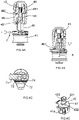
Figures 4A to 4D show parts of the irrigation connector ofFigures 3A and 3B in more detail.Figure 4A shows the irrigation connector with a hollow needle in a retracted position, whilstFigure 4B shows the irrigation connector with the needle in an extended position.Figure 4C shows a safety lock for blocking movement of the needle from the retracted position shown inFigure 4A and Figure 4D shows a subpart of the irrigation connector in isolation; -
Figures 5A and 5B show cutaway portions of the irrigation connector shown inFigures 3A and 3B , illustrating anti-rotation features; -
Figure 6A and 6B show the irrigation connector ofFigures 3A and Figure 3B with a door portion of a retainer clip of the irrigation connector in a closed position inFigure 6A and an open position inFigure 6B ; -
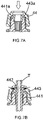
Figures 7A and 7B show detail of a water outlet portion of the irrigation connector shown inFigures 3A and 3B , withFigure 7A showing the outlet portion without a component inserted into the outlet portion andFigure 7B showing a component inserted into the outlet portion and clamped in position; -
Figure 8 shows a ground spike which forms part of the irrigation connector arrangement shown inFigure 3A and 3B in isolation; -
Figures 9A-9E show the irrigation connector arrangement ofFigures 3A and 3B installed in different configurations on a supply hose; and -
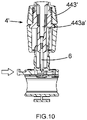
Figure 10 shows a modified irrigation connector. -
Figure 1 schematically shows a micro irrigation system of the type which may be used for watering plants in, for example, a domestic garden or other similar situation. The micro irrigation system comprises asupply hose 1 which is connected to a water supply (not shown). Mounted on thesupply hose 1 are a plurality ofirrigation connector arrangements 2 which serve to make a connection to the water supply hose such that water flowing in the water supply hose can be tapped off by theirrigation connector arrangement 2 and allowed to leave thesupply hose 1 for watering purposes. Eachirrigation connector arrangement 2 may have connected to it a respectivewater outlet component 3, such as for example a further length of hose or tubing, a dripper unit, a sprinkler unit, or so on. - In such an irrigation system, the
water supply hose 1 andoutlet components 3 may be standard commercially available products. For example thewater supply hose 1 may be a length of standard garden hose. -
Figure 2 shows one of the irrigation connector arrangements ofFigure 1 in more detail whilst mounted on thewater supply hose 1. On the other hand,Figures 3A and 3B show the irrigation connector arrangement in isolation. - The irrigation connector arrangement comprises
irrigation connector 4 mounted to aground spike 5 for securing theirrigation connector 4 and hence a carried supply hose in position as schematically illustrated inFigures 1 and2 . In the present embodiment theirrigation connector 4 is arranged for movement relative to theground spike 5, such that theirrigation connector 4 may be orientated at different orientations relative to thespike 5. For example inFigure 3A theirrigation connector 4 is shown in an upright (or vertical) position whereas inFigure 3B theirrigation connector 4 is shown in a horizontal position. - The
irrigation connector 4 comprises ahose retaining portion 41 for holding thesupply hose 1 as shown inFigures 1 and2 . Theneedle connector 4 further comprises ahollow needle 6 with anopen side window 61, which is arranged for projecting into a hose receiving region of thehose retaining portion 41, so as to penetrate into the interior of asupply hose 1 when located in thehose retaining portion 41. - As will be described in more detail below, the
irrigation connector 4 comprises a drive mechanism for driving thehollow needle 6 from a retracted position where theneedle 6 does not extend into the hose receiving region towards the extended position shown inFigure 3B where it can penetrate through the wall of a carried supply hose. - Referring now to
Figures 4A to 4D as well asFigures 3A and 3B , theirrigation connector 4 comprises aneedle housing portion 42 in which theneedle 6 is housed in a retracted position as shown inFigure 4A and which, in the present embodiment, is formed together as one moulding with thehose retaining portion 41. Theirrigation connector 4 also comprises awater outlet portion 43 which comprises a sealingclamp portion 44 for connecting anoutlet component 3 such as a dripper, sprinkler unit or tubing to theirrigation connector 4 and aneedle holding portion 45 for holding thehollow needle 6. - The distal end of the
needle 6 is concealed when in the retracted position which helps prevent accidental injury and damage (to the needle and/or other objects). - The
needle holding portion 45 and clampingportion 44 have a hollow interior which is connected to the hollow interior of thehollow needle 6, such that when thehollow needle 6 penetrates into the interior of a carriedsupply hose 1, there is a fluid communication path between the interior of thesupply hose 1 and the interior of theirrigation connector 4 and any water outlet component 3 (seeFigures 1 and2 ) held in theirrigation connector 4. - The
irrigation connector 4 comprises adrive collar 46 for use in driving theneedle 6 between the retracted position shown inFigure 4A and the extended position shown inFigure 4B (and for example 3B). Thedrive collar 46 is arranged to act on theneedle holding portion 45. - The
hose retaining portion 41 andneedle housing portion 42 are formed in one piece in the present embodiment and are shown together inFigure 4D . Some features of theneedle housing portion 42 are best seen in this Figure. - The
needle housing portion 42 carries a twostart helix 421 and thedrive collar 46 has a corresponding pair offollower projections 461, which run in the twostart helix 421, such that rotational movement of thedrive collar 46 around the axis of theneedle housing portion 42 will cause axial movement of thedrive collar 46, and henceneedle holder portion 45 andneedle 6, relative to theneedle housing portion 42. The two starthelix 421 is arranged so that a 270° rotation of thedrive collar 46 moves theneedle 6 from the retracted to the extended position. - Each track in the two
start helix 421 comprises a corresponding detent portion 422 (one of which can be seen inFigure 4D ) over which therespective follower projection 461 rides as thedrive collar 46 moves to the end of thehelix 421 corresponding to theneedle 6 being in the extended position. Thisdetent portion 422 co-operates with therespective follower projection 461 as interacting detent portions to provide resistance against movement of thedrive collar 46 away from this position that corresponds to theneedle 6 being fully extended. This helps prevent accidental movement of theneedle 6 away from the extended position. - In alternatives a different form of drive mechanism may be provided - for example in one alternative the drive collar may run on a more conventional thread requiring multiple turns between the retracted and extended position; or in another the user may have to push the needle into the extended position by sliding the drive collar forwards without the mechanical advantage provided by camming portions such as a thread or two start helix.
- In alternatives at least part of the external surface of the
needle housing portion 42 may be of a different colour than thedrive collar 46 and/orhose retaining portion 41. This can help indicate when theneedle 6 is in the retracted position. In such a case theneedle housing portion 42 may be part of a "two shot" injection moulded component. - The
irrigation connector 4 is constructed so that theneedle housing portion 42 is provided within thedrive collar 46 and theneedle holding portion 45 is provided within theneedle housing portion 42. These portions may all be generally cylindrical and arranged concentrically one inside the other. - Whilst the
drive collar 46 is arranged to act on theneedle holding portion 45 for providing axial drive, thedrive collar 46 is free to rotate relative to theneedle holding portion 45. As can be seen inFigures 4A, 4B and5A , theneedle holding portion 45 comprises aflange portion 451 which resides in a correspondingannular recess 462 in thedrive collar 46. Thisannular recess 462 allows rotation of theflange portion 451 relative thereto whilst axial movement between theflange portion 451 and theannular recess 462 is resisted. - It is desirable that the
needle holding portion 45 and hence thewater outlet portion 43 do not rotate with thedrive collar 46 when the irrigation connector is operated to drive theneedle 6 into asupply hose 1. This is because it means that rotation of any outlet components connected to thewater outlet portion 43 is avoided. It will be seen that this is particularly attractive where the water outlet component may be tubing to which other parts are connected. - To further help ensure against rotation of the
water outlet portion 43 when theirrigation connector 4 is operated, keying is provided between thewater outlet portion 43 and theneedle housing portion 42 and hencehose retaining portion 41. -
Anti-rotation ribs 423 are provided on the internal surface of theneedle housing portion 42, as may be seen inFigures 4D ,5A and 5B . These are received in respective receivinggrooves 452 provided in theneedle holding portion 45. Thus thewater outlet portion 43 will tend to be held against rotation relative to thehose retaining portion 41 and hence thesupply hose 1 when the irrigation connector is mounted in position on asupply hose 1. - The
irrigation connector 4 comprises a safety lock 7 as may be best seen inFigures 4A to 4C which is provided to help against accidental exposure of theneedle 6. The safety lock 7 comprises amoveable plate 71 with aneedle blocking portion 72 and defining aneedle accepting aperture 73. Themoveable plate 71 is housed in thehose retaining portion 41. Themoveable plate 71 is moveable between a position in which theneedle blocking portion 72 blocks movement of theneedle 6 away from the retracted position shown inFigure 4A towards the extended position shown inFigure 4B . On the other hand when themoveable plate 71 is moved so that theneedle accepting aperture 73 is aligned with theneedle 6, theneedle 6 may be moved from the retracted position as shown inFigure 4A to the extended position as shown inFigure 4B with theneedle 6 passing through theaperture 73. - The safety lock also comprises a spring means 74 for biasing the
moveable plate 71 to the blocking position. In the present embodiment the spring means 74 is formed as an integral spring as part of themoveable plate 71. That is to say movement of themoveable plate 71 is allowed by deformation of thespring portion 74 of the plate material. When theneedle 6 is in the extended position passing through theneedle accepting aperture 73, themoveable plate 71 is held in position against action of thespring 74 by virtue of theneedle 6 residing in theaperture 73. - Thus in operation a user depresses the safety lock 7 against the action of the
spring portion 74, aligning the needle accepting aperture 53 with theneedle 6, allowing subsequent movement of theneedle 6 from the retracted position shown inFigure 4A , towards the extended position shown inFigure 4B , by use of the drive mechanism, in particular, by rotation of thedrive collar 46. - Referring now particularly to
Figures 6A and 6B , thehose retaining portion 41 defines a generally cylindrical hose receiving region and has an internal generally cylindricalhose supporting surface 41a (also visible for example inFigure 4D ). Thehose retaining portion 41 comprises adoor portion 411 which is moveable between a closed position as shown in, for example,Figure 6A and an open position as shown inFigure 6B . Thedoor portion 411 is joined to the remainder of thehose retaining portion 41 via a plastic hinge. When in the open position, as shown inFigure 6B , an opening is created in thehose retaining portion 41, and in particular in thehose supporting wall 41a, though which a length ofsupply hose 1 may be inserted (by movement in a radial direction of the hose). Once thehose 1 is in position in the hose receiving region thedoor portion 411 may be closed. Thus thisdoor portion 411 provides a convenient way for mounting theirrigation connector 4 on thesupply hose 1. Thedoor portion 411 is arranged to latch into the closed position with the remainder of thehose retaining portion 41 by virtue of inter engaginglatching portions - The
irrigation connector 4 is arranged to help prevent accidental opening of thedoor portion 411 when theneedle 6 is in the extended position, as shown inFigure 6A . In the present embodiment this is achieved by virtue of the fact that when thedrive collar 46 is in the position corresponding to theneedle 6 being extended, as shown inFigure 6A , thedrive collar 46 obstructs opening of thedoor portion 411. In particular thedrive collar 46 is disposed so as to resist unlatching of theinter engaging portions drive collar 46 is moved to the position as shown inFigure 6B , corresponding to theneedle 6 being in the retracted position, thedrive collar 46 no longer obstructs opening of thedoor portion 411. - The
door portion 411 may comprise atab portion 411c for use in opening thedoor portion 411. In opening thedoor portion 411 the user may depress thedoor portion tab 411c in a direction away from thedrive collar 46, which tends to cause the respective engagingportion 411a to move upwards out of engagement with thecorresponding engagement portion 41b of the remainder of thehose retaining portion 41 if thedoor portion 411 is to be unlatched. With thedrive collar 46 in the position corresponding to theneedle 6 being extended, this upward movement is effectively blocked. - In the present embodiment, to further resist undesired opening of the
door portion 411, the door portion carries aprojection 411b which engages with a corresponding recess (not shown) in the underside of thedrive collar 46 when thedrive collar 46 is in the position corresponding to theneedle 6 being in the extended position. - It may be noted that axial drive of the
needle 6 as referred to above corresponds, in the current embodiment, to movement of theneedle 6 in a generally radial direction relative to asupply hose 1 held in thehose retaining portion 41. Further it corresponds to movement in a radial direction relative to the cylindrical hose receiving region and/or cylindricalhose supporting surface 41a. -
Figures 7A and 7B show more detail of the clampingportion 44 of thewater outlet portion 43. The clamping portion comprises a threadedseat portion 441 comprising a plurality ofdeformable finger portions 441a. Theseat portion 441 supports atubular sealing element 442 so as to be surrounded by thefinger portions 441a. A clampingnut 443 is provided which can be tightened onto the threadedseat portion 441 and which is arranged to act on thefinger portions 441a. The clampingnut 443 has achamfer portion 443a for acting on the distal ends of thefinger portions 441a and tending to drive them inwards as thenut 443 is tightened onto theseat portion 441. With the clampingnut 443 in a non-tightened position, as shown inFigure 7A , awater outlet component 3 may be introduced into the clampingportion 44 such that it resides within thetubular sealing element 442. As thenut 443 is tightened onto theseat 441 the plurality offingers 441a are driven inwards under action of the clampingnut 443 forcing thetubular sealing element 442 into contact with a carried water outlet component, for example a length of tubing T, as illustratively shown inFigure 7B . - This clamping arrangement means that watering
outlet components 3 having a range of different external diameters may be sealingly connected with theoutlet portion 43 to facilitate use of the irrigation connector with, for example, tubing having slightly different diameters as well as dripper components, sprinkler components and so on, which may all have different external diameters against which a seal needs to be made. Thus theirrigation connector 4 is multi-functional and helps minimise the number of different components that are needed to set up an irrigation system. A kit may comprise a number of irrigation connectors, irrigation tubing, and at least one dripper or sprinkler unit. Ground spikes and/or supply hose may also be included. - As mentioned above in relation to
Figures 3A and 3B , theirrigation connector 4 is arranged to be orientatable at different angles relative to theground spike 5. Theground spike 5 is shown in isolation inFigure 8 . - The
irrigation connector 4 and ground spike 5 comprisecomplementary attachment portions connector 4 to be mounted on thespike 5 and the orientation of theconnector 4 to be varied relative to thespike 5. Theattachment portion 47 on theirrigation connector 4 extends part way round the retainingportion 41 so as to present a plurality of different angularly spaced attachments regions at which theattachment portion 57 of the spike may be selectively located. - The
attachment portion 47 on theirrigation connector 4 comprises arunner 47 which is accepted in aslot 57 in the attachment portion on thespike 5. - The
attachment portions irrigation connector 4 is altered relative to thespike 5. Theattachment portion 47 on theirrigation connector 4 comprises a series of projections and recesses 47a and 47b (seeFigure 3A and 3B ) and the attachment portion on the spike comprises a pair ofprojections 57a. Theprojections 57a on thespike 5 are arranged to ride over a respective one of theprojections 47a on theirrigation connector 4 as theirrigation connector 4 is moved from one indexed position determined by respective one of therecesses 47b to another. When thespike 5 is mounted on theirrigation connector 4 therunner 47 is captured in theslot 57. Therunner 47 is mounted on a supportingstem 47c and projects on either side of the stem.Arms 57b of theattachment portion 57 on thespike 5 wrap around the extending portions of therunner 47 to capture therunner 47. Resilience in thearms 57b allows the indexing movement. Theprojections 57a on thespike 5 act on a face of the retainingportion 41 which is opposite the extending portions of the runner. -
Figures 9A to 9E show the irrigation connector arrangement ofFigures 3A and 3B in different orientations and configurations.Figure 9A shows the irrigation connector arrangement in a vertical (or upright) configuration.Figure 9B shows the irrigation connector arrangement in a horizontal (or transverse) orientation.Figure 9C shows the irrigation connector arrangement in a 45° orientation.Figure 9D shows the irrigation connector arrangement in a vertical (or upright) configuration with a sprinkler mounted in thewater outlet portion 43.Figure 9E shows the irrigation connector arrangement in a horizontal (or transverse) arrangement with a micro tube fitted to thewater outlet portion 43, which tube leads to a stand alone dripper unit. -
Figure 10 shows a modifiedirrigation connector 4'. This is the same as theirrigation connector 4 described above except that the clampingnut 443 is replaced by a shrubbier nut 443'. The shrubbier nut 443' allows theirrigation connector 4 to act as a mini sprinkler without using additional components. When tightened right down, acentral pin 443a' of the nut 443' seals the connector by virtue of thepin 443a' blocking the end of theneedle 6 so that no water escapes. As the nut is loosened, water is allowed to escape from holes (not shown) in the nut head forming a mini sprinkler. - In a further alternative a dripper nut operating on a similar principle may be provided instead of or as well as (for interchangeable use) the shrubbier nut.
Claims (19)
- An irrigation connector for tapping into a water supply hose (1), the connector comprising a retaining portion (41) for holding a supply hose in a hose receiving region of the retaining portion and a hollow needle (6) mounted for movement relative to the retaining portion (41) between a retracted position in which the distal end of the needle is concealed and an extended position in which the needle (6) extends into the hose receiving region for penetrating a supply hose held in the retaining portion (41) to create a fluid communication path between an interior of the needle and an interior of a supply hose held in the retaining portion, wherein the hose receiving region is bounded by an encircling hose supporting surface (41a) and the retaining portion (41) comprises a door portion (411) moveable between a closed position and an open position which creates an opening in the hose supporting surface for allowing introduction and removal of a length of supply hose,
wherein the irrigation connector further comprises a needle drive arrangement (46, 421) for driving the needle towards the extended position, a needle housing portion (42) for housing the needle (6) in the retracted position, and the drive arrangement comprises a drive collar (46) for driving the needle (6) relative to the needle housing portion; characterized by the drive arrangement being arranged so that whilst axial drive is transferred to the needle (6), the drive collar (46) is arranged to rotate freely relative to the needle. - An irrigation connector according to claim 1 comprising a water outlet portion (43) for accepting water from the interior of the needle (6) and passing water out of the connector.
- An irrigation connector according to claim 2 in which the water outlet portion (43) is keyed with the retaining portion (41) to resist relative rotation between the retaining portion and the water outlet portion.
- An irrigation connector according to claim 1 in which the needle housing portion (42) and drive collar (46) have respective corresponding detent portions for resisting movement of the drive collar relative to the housing portion, when the needle is in the extended position, which movement would serve to retract the needle.
- An irrigation connector according to claim 4 when dependent on claim 2 or claim 3, wherein the drive mechanism is arranged so that whilst axial drive is transferred to the needle (6), the drive collar (46) is arranged to rotate freely relative to the water outlet portion.
- An irrigation connector according to any preceding claim comprising a releasable safety lock (7) for selectively blocking movement of the needle from the retracted to the extended position.
- An irrigation connector according to claim 6 in which the safety lock (7) comprises a moveable plate (71) having a needle blocking portion and including an aperture (73) through which the needle (6) may pass, the moveable plate being moveable between a first, blocking, position where the needle blocking portion blocks movement of the needle towards the extended position and a second position where the needle can pass through the aperture.
- An irrigation connector according to claim 7 in which the moveable plate (70) is biased towards the blocking position, the moveable plate comprising a spring portion (74) for providing said bias, and the blocking portion and the spring portion being of a single piece of material.
- An irrigation connector according to any preceding claim in the connector is arranged to block opening of the door portion (411) when the needle (6) is in the extended position.
- An irrigation connector according to claim 9 when dependent directly or indirectly on claim 3 in which the drive arrangement is arranged to block opening of the door portion (411) when the needle (6) is in the extended position.
- An irrigation connector according to claim 10 in which, where the needle drive arrangement comprises a drive collar (46), the drive collar is arranged to block opening of the door portion (411) when the drive collar (46) is in a position corresponding to the needle (6) being in the extended position.
- An irrigation connector according to claim 2 or any one of claims 3 to 11 when dependent on claim 2 in which the water outlet portion (43) comprises a sealing clamp arrangement (44) for connecting an outlet component to the irrigation connector, wherein
the sealing clamp arrangement (44) comprises a tubular sealing element (442) having an internal surface for sealing against an inserted outlet component, a seat portion (441) receiving the tubular sealing element and comprising a plurality of resilient finger portions (441a) for acting on an external surface of the sealing element and a clamping nut (443) for driving the resilient finger portions inwardly towards the axis of the sealing element as the clamping nut is tightened onto the seat portion to compress the sealing element into contact with an inserted outlet component. - An irrigation connector arrangement comprising an irrigation connector (4), according to any preceding claim, and a ground spike (5) for securing the needle connector in position.
- An irrigation connector arrangement according to claim 13 in which the irrigation connector (4) and spike (5) comprise complementary attachment portions (47, 57) allowing the connector (4) to be mounted on the spike (5) and the orientation of the connector to be varied relative to the spike.
- An irrigation connector arrangement according to claim 14 in which the attachment portion (47) on the connector extends at least part way around the retaining portion (41) so as to present a plurality of different angularly spaced attachment regions at which the attachment portion (57) of the spike (5) may be selectively located.
- An irrigation connector arrangement according to claim 14 or claim 15 in which the complementary attachment portions (47, 57) comprise indexing means (47a, 47b) for indexing relative movement of the attachment portions as the orientation of the connector is altered relative to the spike.
- An irrigation connector arrangement according to claim 16 in which the indexing means comprises a series of projections and recesses (47a, 47b) on the attachment portion provided on the connector (4), and a projection (57a) on the attachment portion on the spike (5), which is arranged to ride over a respective one of the projections on the connector as the connector is moved from one indexed position, determined by a respective recess to another.
- An irrigation connector kit comprising an irrigation connector (4) according to any one of claims 1 to 12 and at least two outlet components (3), each arranged for selective mounting in the outlet portion (43), one of the outlet components being hose or tubing and another being a dripper unit or a sprinkler unit.
- An irrigation system comprising a supply hose, and at least two irrigation connectors (4) according to any one of claims 1 to 12, each irrigation connector (4) being mounted on the supply hose (1) with the supply hose held in the retaining portion and a fluid communication path created between an interior of the needle and an interior of the supply hose, wherein hose or tubing is held in the water outlet portion (43) of one of the irrigation connectors and a dripper unit or sprinkler unit is held in the water outlet portion (43) of another of the irrigation connectors.
Applications Claiming Priority (2)
| Application Number | Priority Date | Filing Date | Title |
|---|---|---|---|
| GB1505751.6A GB2536960B (en) | 2015-04-02 | 2015-04-02 | Irrigation connectors |
| PCT/GB2016/050843 WO2016156814A1 (en) | 2015-04-02 | 2016-03-24 | Irrigation connectors |
Publications (2)
| Publication Number | Publication Date |
|---|---|
| EP3277074A1 EP3277074A1 (en) | 2018-02-07 |
| EP3277074B1 true EP3277074B1 (en) | 2022-04-27 |
Family
ID=53190142
Family Applications (1)
| Application Number | Title | Priority Date | Filing Date |
|---|---|---|---|
| EP16712436.1A Active EP3277074B1 (en) | 2015-04-02 | 2016-03-24 | Irrigation connectors |
Country Status (9)
| Country | Link |
|---|---|
| US (1) | US10863680B2 (en) |
| EP (1) | EP3277074B1 (en) |
| CN (1) | CN107426976B (en) |
| AU (1) | AU2016240031C1 (en) |
| ES (1) | ES2916776T3 (en) |
| GB (1) | GB2536960B (en) |
| PL (1) | PL3277074T3 (en) |
| PT (1) | PT3277074T (en) |
| WO (1) | WO2016156814A1 (en) |
Families Citing this family (20)
| Publication number | Priority date | Publication date | Assignee | Title |
|---|---|---|---|---|
| US7648085B2 (en) | 2006-02-22 | 2010-01-19 | Rain Bird Corporation | Drip emitter |
| US10440903B2 (en) | 2012-03-26 | 2019-10-15 | Rain Bird Corporation | Drip line emitter and methods relating to same |
| US9877440B2 (en) | 2012-03-26 | 2018-01-30 | Rain Bird Corporation | Elastomeric emitter and methods relating to same |
| US10285342B2 (en) | 2013-08-12 | 2019-05-14 | Rain Bird Corporation | Elastomeric emitter and methods relating to same |
| USD811179S1 (en) | 2013-08-12 | 2018-02-27 | Rain Bird Corporation | Emitter part |
| US10631473B2 (en) | 2013-08-12 | 2020-04-28 | Rain Bird Corporation | Elastomeric emitter and methods relating to same |
| US9883640B2 (en) | 2013-10-22 | 2018-02-06 | Rain Bird Corporation | Methods and apparatus for transporting elastomeric emitters and/or manufacturing drip lines |
| US10330559B2 (en) | 2014-09-11 | 2019-06-25 | Rain Bird Corporation | Methods and apparatus for checking emitter bonds in an irrigation drip line |
| US10375904B2 (en) | 2016-07-18 | 2019-08-13 | Rain Bird Corporation | Emitter locating system and related methods |
| US11051466B2 (en) | 2017-01-27 | 2021-07-06 | Rain Bird Corporation | Pressure compensation members, emitters, drip line and methods relating to same |
| US10626998B2 (en) | 2017-05-15 | 2020-04-21 | Rain Bird Corporation | Drip emitter with check valve |
| USD883048S1 (en) | 2017-12-12 | 2020-05-05 | Rain Bird Corporation | Emitter part |
| US11985924B2 (en) | 2018-06-11 | 2024-05-21 | Rain Bird Corporation | Emitter outlet, emitter, drip line and methods relating to same |
| US12207599B2 (en) | 2021-10-12 | 2025-01-28 | Rain Bird Corporation | Emitter coupler and irrigation system |
| USD996566S1 (en) * | 2021-11-17 | 2023-08-22 | Roots Sustainable Agricultural Technologies Ltd. | Adapter for pipe joints |
| CN114027140B (en) * | 2021-11-17 | 2023-05-12 | 福建省春秋农林科技有限公司 | Large-area irrigation device and irrigation method |
| USD1027584S1 (en) * | 2022-06-10 | 2024-05-21 | Matthew Janney | Irrigation spike with spike feature |
| US20240164264A1 (en) * | 2022-11-23 | 2024-05-23 | Robert G. Summers | Root irrigation spike apparatus |
| IT202300001029A1 (en) * | 2023-01-24 | 2024-07-24 | Roviaro Simone Az Agricola Le Giare | FIXING DEVICE FOR IRRIGATION HOSES |
| TWI910683B (en) * | 2024-06-20 | 2026-01-01 | 羿豐精密科技有限公司 | Sprinkler |
Citations (1)
| Publication number | Priority date | Publication date | Assignee | Title |
|---|---|---|---|---|
| US5105844A (en) * | 1990-09-24 | 1992-04-21 | King Lloyd H Sr | Two step branch forming attachment |
Family Cites Families (27)
| Publication number | Priority date | Publication date | Assignee | Title |
|---|---|---|---|---|
| US3361363A (en) | 1965-10-22 | 1968-01-02 | Robert S. Babington | Watering device |
| FR2135738A5 (en) | 1971-04-26 | 1972-12-22 | Geffroy Robert | |
| US3973732A (en) | 1971-12-30 | 1976-08-10 | Diggs Richard E | Quick-connect fittings for a trickle type irrigation system |
| US3806031A (en) | 1973-07-05 | 1974-04-23 | D Olson | Snap-on emitter |
| US3966233A (en) | 1974-08-16 | 1976-06-29 | Diggs Richard E | Irrigation apparatus |
| FR2503534A1 (en) | 1981-04-09 | 1982-10-15 | Bourget Maurice | IMPROVEMENTS IN PUNCTUAL IRRIGATION DEVICES |
| AU531948B3 (en) * | 1982-12-07 | 1983-11-10 | Bowen James Vincent Seaton | Drip irrigation flow control |
| US4611624A (en) * | 1985-09-12 | 1986-09-16 | Watsco, Inc. | Line piercing valve assembly |
| FR2652597B1 (en) | 1989-09-29 | 1992-01-24 | Hutchinson Sa | PUNCTUAL IRRIGATION APPARATUS WITH CONNECTION DERIVATIONS. |
| DE9007363U1 (en) | 1990-02-08 | 1991-06-13 | Alfred Kärcher GmbH & Co, 7057 Winnenden | Coupling for the pressure line of a high-pressure cleaning device |
| IL106572A0 (en) | 1992-11-19 | 1993-12-08 | Paskal Avizarey Kshira Ltd | Outlet connector for irrigation pipe |
| FR2722646B1 (en) | 1994-07-21 | 1996-09-27 | Tecnoma | LOCALIZED IRRIGATION DEVICE |
| US5694972A (en) * | 1996-06-27 | 1997-12-09 | Tom King Harmony Products, Inc. | Saddle tee for irrigation lines |
| CN2358311Y (en) * | 1998-11-10 | 2000-01-12 | 陈庆林 | Triangular valve |
| US6216723B1 (en) * | 1999-11-05 | 2001-04-17 | Tom King Harmony Products, Inc. | Self-tapping tee |
| US6510865B2 (en) * | 2000-02-18 | 2003-01-28 | Lloyd Herbert King, Jr. | Tap and saddle for forming a hinged coupon |
| US6758410B2 (en) * | 2001-12-17 | 2004-07-06 | Wen-Li Kuo | Retaining supporter of rotary sprinkler |
| US6986532B1 (en) * | 2002-05-03 | 2006-01-17 | Tom King Harmony Products, Inc. | Saddle tee and tap for irrigation lines |
| US6820647B1 (en) * | 2002-05-08 | 2004-11-23 | Westlock Controls Corporation | Valve position monitor |
| US7066403B2 (en) * | 2002-11-07 | 2006-06-27 | L.R. Nelson Corporation | Sprinkling system and method |
| US7150289B2 (en) * | 2004-09-27 | 2006-12-19 | Duane D. Robertson | Removable, snap-on saddle and tap for irrigation pipes |
| US7219684B2 (en) * | 2005-01-28 | 2007-05-22 | Rain Bird Corporation | Saddle tee and tool for irrigation lines |
| WO2010127711A1 (en) | 2009-05-08 | 2010-11-11 | Alfred Kärcher Gmbh & Co. Kg | Device for watering an area |
| DE102009020801A1 (en) | 2009-05-08 | 2010-11-11 | Alfred Kärcher Gmbh & Co. Kg | Device for sprinkling a surface |
| EP2440336B1 (en) | 2009-05-19 | 2015-09-09 | Alfred Kärcher GmbH & Co. KG | Sprinkler device |
| CN104303958B (en) * | 2014-11-10 | 2017-06-16 | 四川农业大学 | A kind of automatic protection dripper device |
| GB2536961B (en) * | 2015-04-02 | 2021-02-24 | Exel Industries Sa | Irrigation system ground spikes |
-
2015
- 2015-04-02 GB GB1505751.6A patent/GB2536960B/en active Active
-
2016
- 2016-03-24 EP EP16712436.1A patent/EP3277074B1/en active Active
- 2016-03-24 CN CN201680020538.6A patent/CN107426976B/en active Active
- 2016-03-24 ES ES16712436T patent/ES2916776T3/en active Active
- 2016-03-24 WO PCT/GB2016/050843 patent/WO2016156814A1/en not_active Ceased
- 2016-03-24 AU AU2016240031A patent/AU2016240031C1/en not_active Ceased
- 2016-03-24 PL PL16712436.1T patent/PL3277074T3/en unknown
- 2016-03-24 US US15/562,774 patent/US10863680B2/en active Active
- 2016-03-24 PT PT167124361T patent/PT3277074T/en unknown
Patent Citations (1)
| Publication number | Priority date | Publication date | Assignee | Title |
|---|---|---|---|---|
| US5105844A (en) * | 1990-09-24 | 1992-04-21 | King Lloyd H Sr | Two step branch forming attachment |
Also Published As
| Publication number | Publication date |
|---|---|
| AU2016240031B2 (en) | 2020-02-20 |
| PL3277074T3 (en) | 2022-08-16 |
| AU2016240031A1 (en) | 2017-10-19 |
| EP3277074A1 (en) | 2018-02-07 |
| GB2536960A (en) | 2016-10-05 |
| PT3277074T (en) | 2022-05-04 |
| ES2916776T3 (en) | 2022-07-05 |
| GB201505751D0 (en) | 2015-05-20 |
| CN107426976A (en) | 2017-12-01 |
| AU2016240031C1 (en) | 2020-05-28 |
| US20180359961A1 (en) | 2018-12-20 |
| US10863680B2 (en) | 2020-12-15 |
| WO2016156814A1 (en) | 2016-10-06 |
| CN107426976B (en) | 2023-06-23 |
| GB2536960B (en) | 2021-02-24 |
Similar Documents
| Publication | Publication Date | Title |
|---|---|---|
| AU2016240031C1 (en) | Irrigation connectors | |
| EP3179148B1 (en) | Lock mechanism for tubular body | |
| EP0340518B1 (en) | Quick-release plug-in coupling means for breakaway connection of hoses and fluid conduits | |
| CN102378874B (en) | Connector piece | |
| EP2773465B1 (en) | Jet diffuser with quick-replaceable nozzle for irrigation systems | |
| US10350629B2 (en) | Irrigation system ground spike | |
| US20090278346A1 (en) | Connector | |
| WO2012162554A1 (en) | Conduit coupling apparatus and method | |
| US9403177B2 (en) | Sprinkler with multi-functional, side-load nozzle | |
| US20040089738A1 (en) | Sprinkling system and method | |
| CN105381893A (en) | Sanitary shower | |
| KR101704782B1 (en) | One touch Connecting Valve Assembly for Hose | |
| KR20190097733A (en) | Tube Connector | |
| US9664323B2 (en) | Coupler | |
| KR200475865Y1 (en) | Connection adapter for gas container | |
| JP3711246B2 (en) | One-touch joint | |
| EP3546814B1 (en) | Gardening fluid connection device | |
| US20240359202A1 (en) | Adjustable sprinkler riser | |
| KR20170004410U (en) | A sprinkler | |
| KR200334805Y1 (en) | A line valve | |
| KR200401645Y1 (en) | Holder device for connection of a tap and water supply hose | |
| JP2005291446A (en) | Pipe joint | |
| KR100392059B1 (en) | Branch for valve | |
| EP2867568B1 (en) | Connector assembly | |
| KR20180047254A (en) | Quick Connector |
Legal Events
| Date | Code | Title | Description |
|---|---|---|---|
| STAA | Information on the status of an ep patent application or granted ep patent |
Free format text: STATUS: THE INTERNATIONAL PUBLICATION HAS BEEN MADE |
|
| PUAI | Public reference made under article 153(3) epc to a published international application that has entered the european phase |
Free format text: ORIGINAL CODE: 0009012 |
|
| STAA | Information on the status of an ep patent application or granted ep patent |
Free format text: STATUS: REQUEST FOR EXAMINATION WAS MADE |
|
| 17P | Request for examination filed |
Effective date: 20170921 |
|
| AK | Designated contracting states |
Kind code of ref document: A1 Designated state(s): AL AT BE BG CH CY CZ DE DK EE ES FI FR GB GR HR HU IE IS IT LI LT LU LV MC MK MT NL NO PL PT RO RS SE SI SK SM TR |
|
| AX | Request for extension of the european patent |
Extension state: BA ME |
|
| DAV | Request for validation of the european patent (deleted) | ||
| DAX | Request for extension of the european patent (deleted) | ||
| STAA | Information on the status of an ep patent application or granted ep patent |
Free format text: STATUS: EXAMINATION IS IN PROGRESS |
|
| 17Q | First examination report despatched |
Effective date: 20201207 |
|
| GRAP | Despatch of communication of intention to grant a patent |
Free format text: ORIGINAL CODE: EPIDOSNIGR1 |
|
| STAA | Information on the status of an ep patent application or granted ep patent |
Free format text: STATUS: GRANT OF PATENT IS INTENDED |
|
| INTG | Intention to grant announced |
Effective date: 20211125 |
|
| GRAS | Grant fee paid |
Free format text: ORIGINAL CODE: EPIDOSNIGR3 |
|
| GRAA | (expected) grant |
Free format text: ORIGINAL CODE: 0009210 |
|
| STAA | Information on the status of an ep patent application or granted ep patent |
Free format text: STATUS: THE PATENT HAS BEEN GRANTED |
|
| AK | Designated contracting states |
Kind code of ref document: B1 Designated state(s): AL AT BE BG CH CY CZ DE DK EE ES FI FR GB GR HR HU IE IS IT LI LT LU LV MC MK MT NL NO PL PT RO RS SE SI SK SM TR |
|
| REG | Reference to a national code |
Ref country code: GB Ref legal event code: FG4D |
|
| REG | Reference to a national code |
Ref country code: CH Ref legal event code: EP |
|
| REG | Reference to a national code |
Ref country code: PT Ref legal event code: SC4A Ref document number: 3277074 Country of ref document: PT Date of ref document: 20220504 Kind code of ref document: T Free format text: AVAILABILITY OF NATIONAL TRANSLATION Effective date: 20220428 |
|
| REG | Reference to a national code |
Ref country code: DE Ref legal event code: R096 Ref document number: 602016071474 Country of ref document: DE |
|
| REG | Reference to a national code |
Ref country code: AT Ref legal event code: REF Ref document number: 1486213 Country of ref document: AT Kind code of ref document: T Effective date: 20220515 |
|
| REG | Reference to a national code |
Ref country code: IE Ref legal event code: FG4D |
|
| REG | Reference to a national code |
Ref country code: NL Ref legal event code: FP |
|
| REG | Reference to a national code |
Ref country code: SE Ref legal event code: TRGR |
|
| REG | Reference to a national code |
Ref country code: ES Ref legal event code: FG2A Ref document number: 2916776 Country of ref document: ES Kind code of ref document: T3 Effective date: 20220705 |
|
| REG | Reference to a national code |
Ref country code: LT Ref legal event code: MG9D |
|
| REG | Reference to a national code |
Ref country code: AT Ref legal event code: MK05 Ref document number: 1486213 Country of ref document: AT Kind code of ref document: T Effective date: 20220427 |
|
| PG25 | Lapsed in a contracting state [announced via postgrant information from national office to epo] |
Ref country code: NO Free format text: LAPSE BECAUSE OF FAILURE TO SUBMIT A TRANSLATION OF THE DESCRIPTION OR TO PAY THE FEE WITHIN THE PRESCRIBED TIME-LIMIT Effective date: 20220727 Ref country code: LT Free format text: LAPSE BECAUSE OF FAILURE TO SUBMIT A TRANSLATION OF THE DESCRIPTION OR TO PAY THE FEE WITHIN THE PRESCRIBED TIME-LIMIT Effective date: 20220427 Ref country code: HR Free format text: LAPSE BECAUSE OF FAILURE TO SUBMIT A TRANSLATION OF THE DESCRIPTION OR TO PAY THE FEE WITHIN THE PRESCRIBED TIME-LIMIT Effective date: 20220427 Ref country code: GR Free format text: LAPSE BECAUSE OF FAILURE TO SUBMIT A TRANSLATION OF THE DESCRIPTION OR TO PAY THE FEE WITHIN THE PRESCRIBED TIME-LIMIT Effective date: 20220728 Ref country code: FI Free format text: LAPSE BECAUSE OF FAILURE TO SUBMIT A TRANSLATION OF THE DESCRIPTION OR TO PAY THE FEE WITHIN THE PRESCRIBED TIME-LIMIT Effective date: 20220427 Ref country code: BG Free format text: LAPSE BECAUSE OF FAILURE TO SUBMIT A TRANSLATION OF THE DESCRIPTION OR TO PAY THE FEE WITHIN THE PRESCRIBED TIME-LIMIT Effective date: 20220727 Ref country code: AT Free format text: LAPSE BECAUSE OF FAILURE TO SUBMIT A TRANSLATION OF THE DESCRIPTION OR TO PAY THE FEE WITHIN THE PRESCRIBED TIME-LIMIT Effective date: 20220427 |
|
| PG25 | Lapsed in a contracting state [announced via postgrant information from national office to epo] |
Ref country code: RS Free format text: LAPSE BECAUSE OF FAILURE TO SUBMIT A TRANSLATION OF THE DESCRIPTION OR TO PAY THE FEE WITHIN THE PRESCRIBED TIME-LIMIT Effective date: 20220427 Ref country code: LV Free format text: LAPSE BECAUSE OF FAILURE TO SUBMIT A TRANSLATION OF THE DESCRIPTION OR TO PAY THE FEE WITHIN THE PRESCRIBED TIME-LIMIT Effective date: 20220427 Ref country code: IS Free format text: LAPSE BECAUSE OF FAILURE TO SUBMIT A TRANSLATION OF THE DESCRIPTION OR TO PAY THE FEE WITHIN THE PRESCRIBED TIME-LIMIT Effective date: 20220827 |
|
| REG | Reference to a national code |
Ref country code: DE Ref legal event code: R097 Ref document number: 602016071474 Country of ref document: DE |
|
| PG25 | Lapsed in a contracting state [announced via postgrant information from national office to epo] |
Ref country code: SM Free format text: LAPSE BECAUSE OF FAILURE TO SUBMIT A TRANSLATION OF THE DESCRIPTION OR TO PAY THE FEE WITHIN THE PRESCRIBED TIME-LIMIT Effective date: 20220427 Ref country code: SK Free format text: LAPSE BECAUSE OF FAILURE TO SUBMIT A TRANSLATION OF THE DESCRIPTION OR TO PAY THE FEE WITHIN THE PRESCRIBED TIME-LIMIT Effective date: 20220427 Ref country code: RO Free format text: LAPSE BECAUSE OF FAILURE TO SUBMIT A TRANSLATION OF THE DESCRIPTION OR TO PAY THE FEE WITHIN THE PRESCRIBED TIME-LIMIT Effective date: 20220427 Ref country code: EE Free format text: LAPSE BECAUSE OF FAILURE TO SUBMIT A TRANSLATION OF THE DESCRIPTION OR TO PAY THE FEE WITHIN THE PRESCRIBED TIME-LIMIT Effective date: 20220427 Ref country code: DK Free format text: LAPSE BECAUSE OF FAILURE TO SUBMIT A TRANSLATION OF THE DESCRIPTION OR TO PAY THE FEE WITHIN THE PRESCRIBED TIME-LIMIT Effective date: 20220427 Ref country code: CZ Free format text: LAPSE BECAUSE OF FAILURE TO SUBMIT A TRANSLATION OF THE DESCRIPTION OR TO PAY THE FEE WITHIN THE PRESCRIBED TIME-LIMIT Effective date: 20220427 |
|
| PLBE | No opposition filed within time limit |
Free format text: ORIGINAL CODE: 0009261 |
|
| STAA | Information on the status of an ep patent application or granted ep patent |
Free format text: STATUS: NO OPPOSITION FILED WITHIN TIME LIMIT |
|
| PG25 | Lapsed in a contracting state [announced via postgrant information from national office to epo] |
Ref country code: AL Free format text: LAPSE BECAUSE OF FAILURE TO SUBMIT A TRANSLATION OF THE DESCRIPTION OR TO PAY THE FEE WITHIN THE PRESCRIBED TIME-LIMIT Effective date: 20220427 |
|
| 26N | No opposition filed |
Effective date: 20230130 |
|
| PG25 | Lapsed in a contracting state [announced via postgrant information from national office to epo] |
Ref country code: SI Free format text: LAPSE BECAUSE OF FAILURE TO SUBMIT A TRANSLATION OF THE DESCRIPTION OR TO PAY THE FEE WITHIN THE PRESCRIBED TIME-LIMIT Effective date: 20220427 |
|
| PG25 | Lapsed in a contracting state [announced via postgrant information from national office to epo] |
Ref country code: MC Free format text: LAPSE BECAUSE OF FAILURE TO SUBMIT A TRANSLATION OF THE DESCRIPTION OR TO PAY THE FEE WITHIN THE PRESCRIBED TIME-LIMIT Effective date: 20220427 |
|
| REG | Reference to a national code |
Ref country code: CH Ref legal event code: PL |
|
| PG25 | Lapsed in a contracting state [announced via postgrant information from national office to epo] |
Ref country code: LU Free format text: LAPSE BECAUSE OF NON-PAYMENT OF DUE FEES Effective date: 20230324 |
|
| REG | Reference to a national code |
Ref country code: IE Ref legal event code: MM4A |
|
| PG25 | Lapsed in a contracting state [announced via postgrant information from national office to epo] |
Ref country code: LI Free format text: LAPSE BECAUSE OF NON-PAYMENT OF DUE FEES Effective date: 20230331 Ref country code: IE Free format text: LAPSE BECAUSE OF NON-PAYMENT OF DUE FEES Effective date: 20230324 Ref country code: CH Free format text: LAPSE BECAUSE OF NON-PAYMENT OF DUE FEES Effective date: 20230331 |
|
| PG25 | Lapsed in a contracting state [announced via postgrant information from national office to epo] |
Ref country code: BG Free format text: LAPSE BECAUSE OF FAILURE TO SUBMIT A TRANSLATION OF THE DESCRIPTION OR TO PAY THE FEE WITHIN THE PRESCRIBED TIME-LIMIT Effective date: 20220427 |
|
| PG25 | Lapsed in a contracting state [announced via postgrant information from national office to epo] |
Ref country code: BG Free format text: LAPSE BECAUSE OF FAILURE TO SUBMIT A TRANSLATION OF THE DESCRIPTION OR TO PAY THE FEE WITHIN THE PRESCRIBED TIME-LIMIT Effective date: 20220427 |
|
| PGFP | Annual fee paid to national office [announced via postgrant information from national office to epo] |
Ref country code: ES Payment date: 20250410 Year of fee payment: 10 |
|
| PG25 | Lapsed in a contracting state [announced via postgrant information from national office to epo] |
Ref country code: CY Free format text: LAPSE BECAUSE OF FAILURE TO SUBMIT A TRANSLATION OF THE DESCRIPTION OR TO PAY THE FEE WITHIN THE PRESCRIBED TIME-LIMIT; INVALID AB INITIO Effective date: 20160324 |
|
| PG25 | Lapsed in a contracting state [announced via postgrant information from national office to epo] |
Ref country code: HU Free format text: LAPSE BECAUSE OF FAILURE TO SUBMIT A TRANSLATION OF THE DESCRIPTION OR TO PAY THE FEE WITHIN THE PRESCRIBED TIME-LIMIT; INVALID AB INITIO Effective date: 20160324 |
|
| PG25 | Lapsed in a contracting state [announced via postgrant information from national office to epo] |
Ref country code: TR Free format text: LAPSE BECAUSE OF FAILURE TO SUBMIT A TRANSLATION OF THE DESCRIPTION OR TO PAY THE FEE WITHIN THE PRESCRIBED TIME-LIMIT Effective date: 20220427 |
|
| PGFP | Annual fee paid to national office [announced via postgrant information from national office to epo] |
Ref country code: NL Payment date: 20260226 Year of fee payment: 11 |
|
| PGFP | Annual fee paid to national office [announced via postgrant information from national office to epo] |
Ref country code: SE Payment date: 20260320 Year of fee payment: 11 |
|
| PGFP | Annual fee paid to national office [announced via postgrant information from national office to epo] |
Ref country code: GB Payment date: 20260323 Year of fee payment: 11 |
|
| PGFP | Annual fee paid to national office [announced via postgrant information from national office to epo] |
Ref country code: DE Payment date: 20260313 Year of fee payment: 11 |
|
| PGFP | Annual fee paid to national office [announced via postgrant information from national office to epo] |
Ref country code: BE Payment date: 20260324 Year of fee payment: 11 Ref country code: IT Payment date: 20260309 Year of fee payment: 11 |
|
| PGFP | Annual fee paid to national office [announced via postgrant information from national office to epo] |
Ref country code: FR Payment date: 20260330 Year of fee payment: 11 |
|
| PGFP | Annual fee paid to national office [announced via postgrant information from national office to epo] |
Ref country code: PT Payment date: 20260220 Year of fee payment: 11 |
|
| PGFP | Annual fee paid to national office [announced via postgrant information from national office to epo] |
Ref country code: PL Payment date: 20260223 Year of fee payment: 11 |