EP3276937A1 - Image processing device, image processing method, and program - Google Patents
Image processing device, image processing method, and program Download PDFInfo
- Publication number
- EP3276937A1 EP3276937A1 EP15886376.1A EP15886376A EP3276937A1 EP 3276937 A1 EP3276937 A1 EP 3276937A1 EP 15886376 A EP15886376 A EP 15886376A EP 3276937 A1 EP3276937 A1 EP 3276937A1
- Authority
- EP
- European Patent Office
- Prior art keywords
- pixel
- image
- unit
- value
- image processing
- Prior art date
- Legal status (The legal status is an assumption and is not a legal conclusion. Google has not performed a legal analysis and makes no representation as to the accuracy of the status listed.)
- Withdrawn
Links
Images














Classifications
-
- G—PHYSICS
- G06—COMPUTING OR CALCULATING; COUNTING
- G06T—IMAGE DATA PROCESSING OR GENERATION, IN GENERAL
- G06T5/00—Image enhancement or restoration
- G06T5/70—Denoising; Smoothing
-
- H—ELECTRICITY
- H04—ELECTRIC COMMUNICATION TECHNIQUE
- H04N—PICTORIAL COMMUNICATION, e.g. TELEVISION
- H04N5/00—Details of television systems
- H04N5/14—Picture signal circuitry for video frequency region
- H04N5/21—Circuitry for suppressing or minimising disturbance, e.g. moiré or halo
-
- G—PHYSICS
- G06—COMPUTING OR CALCULATING; COUNTING
- G06T—IMAGE DATA PROCESSING OR GENERATION, IN GENERAL
- G06T5/00—Image enhancement or restoration
- G06T5/20—Image enhancement or restoration using local operators
-
- H—ELECTRICITY
- H04—ELECTRIC COMMUNICATION TECHNIQUE
- H04N—PICTORIAL COMMUNICATION, e.g. TELEVISION
- H04N1/00—Scanning, transmission or reproduction of documents or the like, e.g. facsimile transmission; Details thereof
- H04N1/40—Picture signal circuits
- H04N1/409—Edge or detail enhancement; Noise or error suppression
-
- H—ELECTRICITY
- H04—ELECTRIC COMMUNICATION TECHNIQUE
- H04N—PICTORIAL COMMUNICATION, e.g. TELEVISION
- H04N25/00—Circuitry of solid-state image sensors [SSIS]; Control thereof
- H04N25/60—Noise processing, e.g. detecting, correcting, reducing or removing noise
- H04N25/68—Noise processing, e.g. detecting, correcting, reducing or removing noise applied to defects
-
- H—ELECTRICITY
- H04—ELECTRIC COMMUNICATION TECHNIQUE
- H04N—PICTORIAL COMMUNICATION, e.g. TELEVISION
- H04N25/00—Circuitry of solid-state image sensors [SSIS]; Control thereof
- H04N25/60—Noise processing, e.g. detecting, correcting, reducing or removing noise
- H04N25/68—Noise processing, e.g. detecting, correcting, reducing or removing noise applied to defects
- H04N25/69—SSIS comprising testing or correcting structures for circuits other than pixel cells
-
- H—ELECTRICITY
- H04—ELECTRIC COMMUNICATION TECHNIQUE
- H04N—PICTORIAL COMMUNICATION, e.g. TELEVISION
- H04N25/00—Circuitry of solid-state image sensors [SSIS]; Control thereof
- H04N25/70—SSIS architectures; Circuits associated therewith
- H04N25/76—Addressed sensors, e.g. MOS or CMOS sensors
-
- H—ELECTRICITY
- H04—ELECTRIC COMMUNICATION TECHNIQUE
- H04N—PICTORIAL COMMUNICATION, e.g. TELEVISION
- H04N5/00—Details of television systems
- H04N5/14—Picture signal circuitry for video frequency region
- H04N5/142—Edging; Contouring
-
- H—ELECTRICITY
- H04—ELECTRIC COMMUNICATION TECHNIQUE
- H04N—PICTORIAL COMMUNICATION, e.g. TELEVISION
- H04N5/00—Details of television systems
- H04N5/14—Picture signal circuitry for video frequency region
- H04N5/21—Circuitry for suppressing or minimising disturbance, e.g. moiré or halo
- H04N5/213—Circuitry for suppressing or minimising impulsive noise
-
- G—PHYSICS
- G06—COMPUTING OR CALCULATING; COUNTING
- G06T—IMAGE DATA PROCESSING OR GENERATION, IN GENERAL
- G06T2207/00—Indexing scheme for image analysis or image enhancement
- G06T2207/20—Special algorithmic details
- G06T2207/20172—Image enhancement details
- G06T2207/20192—Edge enhancement; Edge preservation
Definitions
- the present invention relates to an image processing apparatus, an image processing method, and a program that perform direction determination on image data in which blinking defective noise having pixel values varying within a certain range occurs, such as RTS noise that occurs in an image sensor including a plurality of pixels arranged in a two-dimensional matrix.
- CMOS complementary metal oxide semiconductor
- Patent Literature 1 For reducing noise that occurs in image data generated by an image sensor such as a complementary metal oxide semiconductor (CMOS), there has been recently known a technique of reducing noise by determining the direction of an edge based on a pixel value of a pixel of interest in an image corresponding to image data, and pixel values of neighboring pixels surrounding the pixel of interest, and performing noise reduction processing using the determination result (refer to Patent Literature 1).
- CMOS complementary metal oxide semiconductor
- Patent Literature 1 JP 2014-225787 A
- the present invention has been contrived in view of the foregoing, and the object of the present invention to provide an image processing apparatus, an image processing method, and a program that can accurately perform direction determination on image data in which blinking defective noise having pixel values varying within a certain range occurs, such as RTS noise.
- an image processing apparatus for performing image processing on image data including blinking defective noise that has been generated by an image sensor including pixels arranged in a two-dimensional matrix, the pixels being configured to receive light from outside and to generate a signal according to a light receiving amount, and readout circuits configured to read out the signal as a pixel value, and includes: an acquisition unit configured to acquire noise information including position information of a pixel in which there is a possibility that blinking defective noise attributed to the readout circuit occurs; a direction determination unit configured to determine, based on the noise information acquired by the acquisition unit, and pixel values of neighboring pixels surrounding a pixel of interest in an image corresponding to the image data, a direction in which pixel values having highest correlation with a pixel value of the pixel of interest are consecutively arrayed; and an image processor configured to perform image processing on the image data based on a determination result of the direction determination unit.
- the noise information includes information in which the position information and feature data related to the blinking defective noise attributed to the readout circuit are associated.
- the direction determination unit determines the direction based on the feature data, the pixel value of the pixel of interest, and the pixel values of the neighboring pixels.
- the direction determination unit determines the direction using any one value of the pixel value of the pixel of interest, a value obtained by adding the feature data to the pixel value of the pixel of interest, and a value obtained by subtracting the feature data from the pixel value of the pixel of interest.
- the direction determination unit decides a standard pixel from the pixel of interest or the neighboring pixels, and when there is a possibility that the blinking defective noise occurs in the standard pixel, determines the direction by correcting pixel values of pixels other than the standard pixel using the feature data.
- the feature data is any of a noise level of the blinking defective noise and a value calculated based on the noise level.
- the direction determination unit determines the direction by excluding a pixel in which there is a possibility that the blinking defective noise occurs, based on the position information.
- the image processor performs image processing of removing noise in the pixel value of the pixel of interest so as to increase correlation of a pixel value of a pixel in the direction determined by the direction determination unit.
- the image processor performs image processing of removing the blinking defective noise in the pixel value of the pixel of interest so as to increase correlation of a pixel value of a pixel in the direction determined by the direction determination unit.
- the noise information further includes isolated point position information of an isolated point in the image sensor, and the image processor performs image processing of removing the blinking defective noise by excluding the isolated point in the direction, based on the isolated point position information.
- the image processor corrects a pixel value of the isolated point using a pixel value of a pixel in the direction determined by the direction determination unit.
- the image processor performs image processing of interpolating the pixel value of the pixel of interest by estimating the direction determined by the direction determination unit, as an edge.
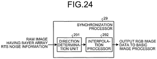
- the image processor performs synchronization processing of the image data based on a determination result of the direction determination unit.
- an image processing method is an image processing method executed by an image processing apparatus for performing image processing on image data including blinking defective noise that has been generated by an image sensor including pixels arranged in a two-dimensional matrix, the pixels being configured to receive light from outside and to generate a signal according to a light receiving amount, and readout circuits configured to read out the signal as a pixel value, and includes: an acquisition step of acquiring noise information including position information of a pixel in which there is a possibility that blinking defective noise attributed to the readout circuit occurs; a direction determination step of determining, based on the noise information acquired by the acquisition unit, and pixel values of neighboring pixels surrounding a pixel of interest in an image corresponding to the image data, a direction in which pixel values having highest correlation with a pixel value of the pixel of interest are consecutively arrayed; and an image processing step of performing image processing on the image data based on a determination result of the direction determination unit.
- a program according to the present invention is a program for causing an image processing apparatus for performing image processing on image data including blinking defective noise that has been generated by an image sensor including pixels arranged in a two-dimensional matrix, the pixels being configured to receive light from outside and to generate a signal according to a light receiving amount, and readout circuits configured to read out the signal as a pixel value, to execute: an acquisition step of acquiring noise information including position information of a pixel in which there is a possibility that blinking defective noise attributed to the readout circuit occurs; a direction determination step of determining, based on the noise information acquired by the acquisition unit, and pixel values of neighboring pixels surrounding a pixel of interest in an image corresponding to the image data, a direction in which pixel values having highest correlation with a pixel value of the pixel of interest are consecutively arrayed; and an image processing step of performing image processing on the image data based on a determination result of the direction determination unit.
- the present invention brings about such an effect that edge direction determination can be accurately performed on image data in which blinking defective noise having values varying at random within a predetermined range occurs, such as RTS noise.
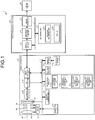
- FIG. 1 is a block diagram schematically illustrating a configuration of an imaging system according to a first embodiment of the present invention.
- An imaging system 1 illustrated in FIG. 1 includes an imaging apparatus 10, an image processing apparatus 20, and a display device 30.
- the imaging apparatus 10 includes an optical system 101, a diaphragm 102, a shutter 103, a driver 104, an image sensor 105, an analog processor 106, an A/D converter 107, an operating unit 108, a memory I/F unit 109, a recording medium 110, a volatile memory 111, a nonvolatile memory 112, a bus 113, an imaging controller 114, and a first external I/F unit 115.
- the optical system 101 is formed by using one or a plurality of lenses.
- the optical system 101 is formed by using a focus lens and a zoom lens.
- the diaphragm 102 adjusts exposure by restricting an entrance amount of light condensed by the optical system 101.
- the diaphragm 102 restricts an entrance amount of light condensed by the optical system 101, under the control of the imaging controller 114.
- an entrance amount of light may be controlled using the shutter 103 or an electrical shutter in the image sensor 105, without using the diaphragm 102.
- the optical system 101 and the diaphragm 102 may be detachable from the imaging apparatus 10.
- the shutter 103 sets a state of the image sensor 105 to an exposure state or a light-shielded state.
- the shutter 103 is formed by using a focal plane shutter or the like.
- an electrical shutter in the image sensor 105 may be used without using the shutter 103.
- the driver 104 drives the optical system 101, the diaphragm 102, and the shutter 103. For example, by moving the optical system 101 along an optical axis O1, the driver 104 changes a zoom magnification of the imaging apparatus 10 or adjusts a focus position.
- the image sensor 105 receives light condensed by the optical system 101, and converts the light into image data (electrical signal) to output the image data.
- the image sensor 105 is formed by using a complementary metal oxide semiconductor (CMOS) including a plurality of pixels arranged in a two-dimensional matrix, or the like.
- CMOS complementary metal oxide semiconductor
- An RGB filter having a Bayer array is arranged on the front surface of each of the pixels.
- the image sensor 105 is not limited to the Bayer array, and may of course have a stacked form such as Fovion, for example.
- a filter to be used is not limited to the RGB filter, and any filter such as a complementary filter can be applied.
- a light source that can emit light having different colors, in a time-division manner may be additionally disposed without disposing a filter on the image sensor 105, and the image sensor 105 may be configured to be able to form a color image using images sequentially captured while changing colors to be emitted. Furthermore, the image sensor 105 may be configured to be able to form a monochrome image without disposing a filter. In addition, the image sensor 105 has an electrical shutter function that can electrically control a light receiving amount.
- FIG. 2 is a schematic diagram schematically illustrating a configuration of a main part of the image sensor 105.
- FIG. 2 illustrates an example of the image sensor 105 in which a readout circuit is shared by a plurality of pixels for enhancing sensitivity by increasing an aperture ratio of the pixels.
- one readout circuit is disposed for eight pixels including two pixels in a horizontal direction (traverse direction) ⁇ four pixels in a vertical direction (longitudinal direction).
- a horizontal direction traverse direction
- ⁇ four pixels in a vertical direction (longitudinal direction).
- one group includes one readout circuit for eight pixels including two pixels in the horizontal direction (traverse direction) ⁇ four pixels in the vertical direction (longitudinal direction). Nevertheless, it is assumed that the aforementioned pixels and the readout circuits are consecutively arranged in the horizontal direction and the vertical direction on the image sensor 105 of this first embodiment.
- the image sensor 105 includes a plurality of pixels 105a (photodiodes) that generates electrical charge corresponding to an exposure amount by receiving light through exposure and performing photoelectric conversion, first switches 105b that are respectively provided for the plurality of pixels 105a, and open and close according to the control of the imaging controller 114, a vertical transfer line 105c that transfers a signal (electrical charge) output from each of the plurality of pixels 105a, in the vertical direction, a floating diffusion (FD) unit 105d that accumulates signals respectively output from the plurality of pixels 105a, an amplifier unit 105e that amplifies the signals output from the FD unit 105d, a second switch 105f that opens and closes according to the control of the imaging controller 114, a control line 105g that controls the second switch 105f, and a transfer line 105h that transfers electrical signals amplified by the amplifier unit 105e.
- a vertical transfer line 105c that transfers a signal (electrical charge) output from each of the plurality of pixels
- the image sensor 105 When reading out signals corresponding to exposure amounts in the pixels 105a (1) to 105a (8), as pixel values, the image sensor 105 having the above-described configuration first sets the FD unit 105d to a reset state, and the imaging controller 114 turns on only the first switch 105b (1). The image sensor 105 thereby transfers electrical charge generated in the pixel 105a (1), to the FD unit 105d. After that, by the imaging controller 114 turning on the second switch 105f, the image sensor 105 causes the amplifier unit 105e to amplify electrical charges accumulated in the FD unit 105d, and reads out (outputs) the electrical charges as pixel values.
- the image sensor 105 transfers electrical charge generated in the pixel 105a (2), to the FD unit 105d.
- the imaging controller 114 turning on the second switch 105f the image sensor 105 causes the amplifier unit 105e to amplify electrical charges accumulated in the FD unit 105d, and reads out the electrical charges as pixel values.
- the image sensor 105 can sequentially output signals corresponding to exposure amounts in the pixels 105a (1) to 105a (8), as pixel values.
- the amplifier unit 105e functions as a readout circuit that reads out electrical charge from each of the plurality of pixels 105a.
- the analog processor 106 performs predetermined analog processing on an analog signal input from the image sensor 105, and outputs the signal to the A/D converter 107. More specifically, the analog processor 106 performs noise reduction processing, gain-up processing, and the like on the analog signal input from the image sensor 105. For example, with respect to the analog signal, the analog processor 106 reduces reset noise or the like, and then performs waveform shaping, and furthermore, performs gain-up so as to have target brightness.
- the A/D converter 107 By performing A/D conversion on the analog signal input from the analog processor 106, the A/D converter 107 generates digital image data (hereinafter, referred to as "RAW image data"), and outputs the image data to the volatile memory 111 via the bus 113.
- the A/D converter 107 may directly output the RAW image data to each unit of the imaging apparatus 10 that is to be described later.
- the aforementioned analog processor 106 and the A/D converter 107 may be provided in the image sensor 105, and the image sensor 105 may directly output the digital RAW image data.
- the operating unit 108 issues various instructions of the imaging apparatus 10. More specifically, the operating unit 108 includes a power switch that switches a power state of the imaging apparatus 10 to an on state or an off state, a release switch that issues a still image capturing instruction, an operating switch that switches various settings of the imaging apparatus 10, a moving image switch that issues a moving image capturing instruction, and the like.
- the recording medium 110 is formed by using a memory card attached from the outside of the imaging apparatus 10, and is detachably attached to the imaging apparatus 10 via the memory I/F unit 109.
- the recording medium 110 may output programs and various types of information to the nonvolatile memory 112 via the memory I/F unit 109 under the control of the imaging controller 114.
- the volatile memory 111 temporarily stores image data input from the A/D converter 107 via the bus 113.
- the volatile memory 111 temporarily stores image data sequentially output by the image sensor 105 for one frame, via the analog processor 106, the A/D converter 107, and the bus 113.
- the volatile memory 111 is formed by using a synchronous dynamic random access memory (SDRAM) or the like.
- SDRAM synchronous dynamic random access memory
- the nonvolatile memory 112 is formed by using a flash memory or the like, and records various programs for operating the imaging apparatus 10, and various types of data used in the execution of the programs.
- the nonvolatile memory 112 includes a program recording unit 112a, an RTS noise information recording unit 112b that records RTS noise position information in which position information of the readout circuit (the amplifier unit 105e) that reads out pixel values, or position information of each of the plurality of pixels 105a, and feature data related to RTS noise attributed to the readout circuit (the amplifier unit 105e) are associated, a random noise model information recording unit 112c that records one or a plurality of random noise models, and an isolated point position information recording unit 112d that records isolated point position information indicating positions of a plurality of isolated point pixels.
- the feature data is any of amplitude (RTS_Value) of RTS noise, occurrence frequency of blinking defective noise, and occurrence frequency of RTS noise smaller than the amplitude of RTS noise.
- the bus 113 is formed by using a transmission path or the like that connects components of the imaging apparatus 10, and transfers various types of data generated in the imaging apparatus 10, to each component of the imaging apparatus 10.
- the imaging controller 114 is formed by using a central processing unit (CPU) or the like, and comprehensively controls the operation of the imaging apparatus 10 by, for example, issuing instructions and transferring data to the units constituting the imaging apparatus 10, according to instruction signals and release signals from the operating unit 108. For example, when a second release signal is input from the operating unit 108, the imaging controller 114 starts control of a capturing operation in the imaging apparatus 10.
- the capturing operation in the imaging apparatus 10 refers to an exposure timing of the image sensor 105, an output timing of an analog signal, and an operation of the analog processor 106 and the A/D converter 107 performing predetermined processing on an analog signal output by the image sensor 105.
- the image data having been subjected to the processing is recorded on the recording medium 110 via the bus 113 and the memory I/F unit 109 under the control of the imaging controller 114.
- the first external I/F unit 115 outputs information input from an external device via the bus 113, to the nonvolatile memory 112 or the volatile memory 111, and outputs information recorded in the volatile memory 111, information recorded in the nonvolatile memory 112, and image data generated by the image sensor 105, to the external device via the bus 113. More specifically, the first external I/F unit 115 outputs, via the bus 113, image data generated by the image sensor 105, RTS noise information, and random noise model information to the image processing apparatus 20.
- the image processing apparatus 20 includes a second external I/F unit 21, a direction determination unit 22, an image processor 23, a recording unit 24, and a bus 25.
- the second external I/F unit 21 acquires, via the first external I/F unit 115 and the bus 113 of the imaging apparatus 10, the RAW image data generated by the image sensor 105, RTS noise information related to RTS noise that is recorded in the RTS noise information recording unit 112b, isolated point position information recorded in the isolated point position information recording unit 112d, and random noise model information recorded in the random noise model information recording unit 112c, and outputs the RAW image data, the RTS noise information, the isolated point position information, and the random noise model information that have been acquired via the bus 25, to the direction determination unit 22 and the recording unit 24.
- the second external I/F unit 21 and the first external I/F unit 115 are connected via, for example, a control cable, wireless communication, or the like that enables interactive communication of information.
- the second external I/F unit 21 functions as an acquisition unit.
- the direction determination unit 22 acquires, via the second external I/F unit 21, the first external I/F unit 115, and the bus 113, a pixel value of a pixel of interest in a RAW image corresponding to the RAW image data, pixel values of neighboring pixels surrounding the pixel of interest, the RTS noise information, and the isolated point position information, and determines a direction in which pixel values having the highest correlation with the pixel value of the pixel of interest are consecutively arrayed, based on the acquired RTS noise information and the pixel values of the neighboring pixels surrounding the pixel of interest in the RAW image corresponding to the RAW image data.
- FIG. 3 is a block diagram illustrating a functional configuration of the direction determination unit 22.
- the direction determination unit 22 includes a correlation value calculation unit 221 and a direction decision unit 222.
- the correlation value calculation unit 221 calculates correlation values of a pixel value of a pixel of interest in each direction in the RAW image generated by the image sensor 105, and pixel values of neighboring pixels of the pixel of interest.
- the correlation values are values indicating the degree of similarity between the pixel value of the pixel of interest and the pixel values of the neighboring pixels, and values that are based on differences between the pixel value of the pixel of interest and the pixel values of the neighboring pixels, for example.
- the direction decision unit 222 decides a direction in which correlation is the highest, based on the correlation values of the respective directions that have been calculated by the correlation value calculation unit 221. For example, when differences between the pixel value of the pixel of interest and the pixel values of the neighboring pixels are used as the correlation values, a direction in which the differences become the smallest is decided.
- the image processor 23 Based on a determination result of the direction determination unit 22, the image processor 23 performs predetermined image processing on the image data, and outputs the image data to the display device 30.
- predetermined image processing basic image processing is performed including at least optical black reduction processing and white balance adjustment processing, and including synchronization processing of image data, color matrix calculation processing, ⁇ -correction processing, color reproduction processing, edge enhancement processing, noise reduction processing, and the like when the image sensor 105 has the Bayer array.
- the image processor 23 performs image processing for reproducing a natural image, based on preset parameters of each type of image processing.
- the parameters of each type of image processing include values of contrast, sharpness, saturation, white balance, and gradation.
- the recording unit 24 is formed by using a volatile memory and a nonvolatile memory, and records various programs for operating the image processing apparatus 20, and various types of data used in the execution of the programs.
- the recording unit 24 includes a program recording unit 241 for driving the image processing apparatus 20, and a buffer 242 that temporarily stores the RAW image data, the RTS noise information, the isolated point position information, edge variables of a pixel of interest, evaluation values, and the like that have been input from the imaging apparatus 10 via the second external I/F unit 21 and the bus 25.
- the bus 25 is formed by using a transmission path or the like that connects components of the image processing apparatus 20, and transfers various types of data generated in the image processing apparatus 20, to each component of the image processing apparatus 20.
- the display device 30 displays an image corresponding to image data input from the image processing apparatus 20.
- the display device 30 is formed by using a display panel or the like having a liquid crystal, organic Electro Luminescence (EL), or the like.
- the image processing apparatus 20 after the image processing apparatus 20 has performed edge direction determination on image data generated by the image sensor 105, the image processing apparatus 20 performs image processing based on the result of the direction determination, and the display device 30 displays an image corresponding to the image data on which image processing has been performed by the image processing apparatus 20.
- the image data on which image processing has been performed by the image processing apparatus 20 may be recorded in the recording medium 110 or the nonvolatile memory 112 of the imaging apparatus 10 via the second external I/F unit 21, the first external I/F unit 115, and the bus 113.
- FIG. 4 is a diagram illustrating an example of variations in amplifier output that is output from the amplifier unit 105e when RTS noise occurs, in a case in which the image sensor 105 is shielded from light so that light is not emitted onto the image sensor 105.
- FIG. 5 is a diagram illustrating an example of distributions of pixel values read out using the amplifier unit 105e in which RTS noise occurs.
- CDS processing correlated double sampling processing
- the imaging controller 114 turns on a reset switch (not illustrated) of the image sensor 105 to reset electrical charges in the FD unit 105d, and furthermore, the imaging controller 114 turns on the second switch 105f to cause the reset state, and reads out (outputs) a signal in the reset state (reference signal).
- the imaging controller 114 turns on only the first switch 105b (or any of the first switches 105b (1) to 105b (8)), transfers electrical charge generated in the pixel 105a, to the FD unit 105d, and furthermore, causes a readout state (output state) in which the second switch 105f is turned on, and reads out (outputs) a signal in the readout state.
- a signal obtained by subtracting the signal in the reset state (reference signal) from the signal in the readout state is converted as a pixel value.
- a signal is sometimes read out while electrical potential is varying.
- an amplifier output difference between a readout time in the reset state and a readout time in the readout state is larger than -Vrts and smaller than Vrts.
- pixel values read out from the image sensor 105 have values larger than -RTS_Value and smaller than RTS_Value.
- the time ⁇ is considered to be substantially constant if conditions of the image sensor 105 (e.g., temperature, driving voltage, etc.) are constant.
- a pixel value larger than -RTS_Value and smaller than RTS_Value occurs with similar probability.
- the occurrence frequency of these pixel values is defined as anoise.
- the distribution B and the distribution C are similar distributions except that median values are different.
- a ratio of the distribution B or the distribution C to the distribution A is defined as arts.
- the ⁇ rts becomes larger larger as an amplifier output variation cycle of the amplifier unit 105e becomes shorter.
- pixel values read out using the amplifier unit 105e in which RTS noise occurs have distributions as illustrated in FIG. 5 .
- electrical potential in the readout state varies according to an exposure amount. Nevertheless, a change in electrical potential that is caused by RTS noise is constant regardless of an exposure amount.
- RTS noise does not depend on an exposure amount, and has a property of varying at random with respect to a normal pixel value within a range equal to or larger than -RTS_Value and equal to or smaller than RTS_Value.
- the distribution A, the distribution B, and the distribution C are schematically illustrated. Nevertheless, a normal distribution is generally obtained.
- RTS noise is noise attributed to the readout circuit (the amplifier unit 105e)
- the amplifier unit 105e when one readout circuit is shared by the plurality of pixels 105a as illustrated in FIG. 2 , RTS noise having similar properties occur in all the sharing pixels (the pixels 105a (1) to 105a (8)).
- RTS noise sometimes occurs in a column amplifier, a source follower, and the like that is shared in a column direction of the image sensor 105.
- RTS noise having similar properties occurs in all pixels in the column direction that share the same column amplifier and the source follower.
- the present invention can be applied to RTS noise that occurs in circuits other than the readout circuit (the amplifier unit 105e).
- RTS noise is a type of blinking defective noise that occurs in such a manner that, when an image of a subject is fixedly captured in the same condition, a pixel value in the captured image is amplified (varies) within a certain range (equal to or larger than - RTS_Value and equal to or smaller than RTS_Value).
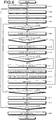
- FIG. 6 is a flowchart illustrating overview of processing executed by the direction determination unit 22, and is a flowchart illustrating overview of direction determination processing of determining a direction.
- FIG. 7 is a diagram schematically illustrating a pixel array of the image sensor 105, and is a diagram illustrating a pixel array of the image sensor 105 having no color filter (monochrome image sensor).
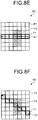
- FIGS. 8A to 8H are diagrams each schematically illustrating an example of a direction in which the correlation value calculation unit 221 performs calculation on a RAW image, and a direction indicated by a dir 1 corresponds to FIG. 8A , a direction indicated by a dir 2 corresponds to FIG. 8B , and so on, and a direction indicated by a dir 8 corresponds to FIG. 8H .
- FIGS. 8A to 8H are diagrams each schematically illustrating an example of a direction in which the correlation value calculation unit 221 performs calculation on a RAW image, and a direction indicated by a dir 1 corresponds to FIG. 8A , a direction indicated by a dir 2 corresponds to FIG. 8B , and so on, and a direction indicated by a dir 8 corresponds to FIG.
- a pixel F1 indicates a normal pixel (not hatched), and a pixel F2 indicates a pixel (hatched) in which there is a possibility that RTS noise occurs
- a thick frame T1 indicates pixels used for direction determination
- an arrow A1 indicates a direction.
- a pixel corresponding to a start point of the arrow A1 is defined as the first pixel
- the next pixel on the arrow A1 is defined as the second pixel
- a pixel corresponding to an end point of the arrow A1 (distal end of the arrow) is defined as the seventh pixel.
- the correlation value calculation unit 221 calculates correlation values in eight directions on a RAW image W1.
- a number indicated by dir is assumed to be equal to or larger than 1 and equal to or smaller than 8.
- the correlation value calculation unit 221 acquires, via the second external I/F unit 21, the first external I/F unit 115, and the bus 113, the isolated point position information from the isolated point position information recording unit 112d, and a RAW image from the volatile memory 111, and determines, based on the acquired isolated point position information, whether an ith pixel or an (i-1)th pixel in the RAW image is an isolated point pixel (step S105).
- the ith pixel is the ith pixel on the arrow A1 extending in the dir direction that is obtained when a pixel of interest in the RAW image is located at the center
- the (i-1)th pixel is the (i-1)th pixel (pixel shifted by one pixel toward a start point side along the arrow A1 extending in the dir direction) on the arrow A1 extending in the dir direction that is obtained when the pixel of interest is located at the center.
- step S105 when the correlation value calculation unit 221 determines that the ith pixel or the (i-1)th pixel in the RAW image is not an isolated point pixel (step S105: No), the direction determination unit 22 advances the processing to step S106 to be described later.
- step S106 based on the RTS noise information acquired from the RTS noise information recording unit 112b, and the RAW image acquired from the volatile memory 111, via the second external I/F unit 21, the first external I/F unit 115, and the bus 113, the correlation value calculation unit 221 sequentially acquires the (i-1)th (the first, the second, and so on, and the seventh from an arrow departure point of the arrow A1 illustrated in FIGS. 8A to 8H ) pixel values in the dir direction. More specifically, as illustrated in FIG. 8A , the correlation value calculation unit 221 acquires, from the RAW image W1, respective pixel values of a pixel N1 at the departure point of the arrow A1 to a pixel N7. In addition, the correlation value calculation unit 221 sequentially stores, into the buffer 242, the (i-1)th pixel value acquired for each of the (i-1)th pixels, by copying all the values in Prev1, Prev2, and Prev3 variables.
- the correlation value calculation unit 221 determines whether there is a possibility that RTS noise occurs in the (i-1)th pixel in the dir direction (step S107).
- the direction determination unit 22 advances the processing to step S108 to be described later.
- the direction determination unit 22 advances the processing to step S109 to be described later.
- the direction determination unit 22 advances the processing to step S109.
- the correlation value calculation unit 221 acquires the ith pixel value in the dir direction in the RAW image acquired from the volatile memory 111 via the second external I/F unit 21, the first external I/F unit 115, and the bus 113 (step S109). In addition, the correlation value calculation unit 221 stores acquired pixel values into the buffer 242 by copying all the values in Curr1, Curr2, and Curr3 variables.
- the correlation value calculation unit 221 determines whether there is a possibility that RTS noise occurs in the ith pixel in the dir direction (step S110).
- the direction determination unit 22 advances the processing to step S111 to be described later.
- the direction determination unit 22 advances the processing to step S112 to be described later.
- the direction determination unit 22 advances the processing to step S112.
- the correlation value calculation unit 221 calculates an absolute value of the minimum difference between the (i-1)th pixel value and the ith pixel value (step S112). More specifically, the correlation value calculation unit 221 calculates an absolute value obtained when a difference becomes the minimum, for all the combinations of Prev and Curr, such as Prev1 and Curr1, Prev1 and Curr2, Prev1 and Curr3, Prev2 and Curr1, and so on, and Prev3 and Curr3.
- Prev and Curr such as Prev1 and Curr1, Prev1 and Curr2, Prev1 and Curr3, Prev2 and Curr1, and so on, and Prev3 and Curr3.
- the correlation value calculation unit 221 determines whether the counter i indicating a position at which a correlation degree is to be obtained represents 7 or less (i ⁇ 7) (step S116).
- the direction determination unit 22 returns the processing to step S105.
- the direction determination unit 22 advances the processing to step S117.
- the correlation value calculation unit 221 determines whether the variable dir indicating a direction in which a correlation value degree is to be calculated is 8 or less (dir ⁇ 8) (step S119).
- the direction determination unit 22 returns the processing to step S102.
- the direction determination unit 22 advances the processing to step S120.
- step S120 the direction decision unit 222 searches ⁇ 1 to ⁇ 8 for the minimum ⁇ dir, and decides a corresponding dir as a direction in which pixel values having the highest correlation with the pixel value of the pixel of interest are consecutively arrayed, and sets the decided direction as a direction determination result.
- the direction determination unit 22 ends this processing.
- the correlation value calculation unit 221 calculates a value obtained by adding RTS_Value to or subtracting RTS_Value from a pixel value of a pixel in which RTS noise occurs, and a direction in which pixel values having the highest correlation with the pixel value of the pixel of interest are consecutively arrayed is determined using the calculated calculation result, direction determination can be accurately performed on image data in which RTS noise occurs.
- the correlation value calculation unit 221 calculates a value obtained by adding RTS_Value to or subtracting RTS_Value from a pixel value of a pixel in which there is a possibility that RTS noise occurs.
- a value obtained by multiplying RTS_Value by a predetermined coefficient equal to or larger than 0 and smaller than 1 may be added or subtracted considering the distribution of RTS noise such as anoise.
- the first modified example of the first embodiment of the present invention differs from the aforementioned first embodiment in the configuration of the image sensor 105 of the imaging system 1. More specifically, while no color filter is provided on a light receiving surface of the image sensor 105 in the aforementioned first embodiment, a color filter having the Bayer array is provided on the light receiving surface of the image sensor 105 in the first modified example of this first embodiment.
- a configuration of an image sensor according to the first modified example of this first embodiment will be described below.
- the same configurations as those in the imaging system 1 according to the aforementioned first embodiment are assigned the same sings, and the description thereof will be omitted.
- FIG. 9 is a diagram schematically illustrating a pixel array of the image sensor according to the first modified example of the first embodiment of the present invention.
- R filters, G filters and B filters that transmit wavelength regions different from each other are provided on the light receiving surface of the image sensor 105i in the Bayer array.
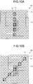
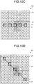
- FIGS. 10A to 10D are diagrams each schematically illustrating an example of a direction in which the correlation value calculation unit 221 performs calculation on the image sensor 105i.
- a pixel F1 indicates a normal pixel (not hatched)
- a pixel F2 indicates a pixel (hatched) in which there is a possibility that RTS noise occurs
- a thick frame T1 indicates pixels used for direction determination
- an arrow A1 indicates a direction.
- numbers indicated by dir are assumed to be directions 1 to 4 in FIGS. 10A to 10D . In other words, by executing the aforementioned direction determination processing with the maximum value of dir in FIG.
- the direction determination unit 22 obtains a value by adding RTS_Value to or subtracting RTS_Value from a pixel in which there is a possibility that RTS noise occurs, and performs direction determination while selecting a value having the highest correlation.
- the direction determination unit 22 thereby determines a direction in which pixel values having the highest correlation with the pixel value of the pixel of interest are consecutively arrayed.
- direction determination can be accurately performed on image data in which RTS noise occurs.
- the direction determination unit 22 may be configured not to distinguish a column in which B pixels provided with B filters are arranged, and a column in which R pixels in which R filters are provided on the light receiving surface are arranged.
- the correlation value calculation unit 221 calculates a value obtained by adding RTS_Value to or subtracting RTS_Value from a pixel value of a pixel in which there is a possibility that RTS noise occurs.
- a value obtained by multiplying RTS_Value by a predetermined coefficient equal to or larger than 0 and smaller than 1 may be added or subtracted considering the distribution of RTS noise such as anoise.
- the second modified example of the first embodiment of the present invention has the same configuration as the imaging system 1 according to the aforementioned first embodiment, and differs only in processing executed by the direction determination unit 22. More specifically, a direction determination unit according to the second modified example of this first embodiment pre-calculates a standard value in each direction in which a correlation degree is to be calculated in a RAW image, and as for a pixel in which there is a possibility that RTS noise occurs, decides a value closest to the standard value by adding RTS_Value to or subtracting RTS_Value from the pixel value, and determines a direction using the decided value.
- processing executed by the direction determination unit according to the second modified example of this first embodiment will be described below.
- the same configurations as those in the imaging system 1 according to the aforementioned first embodiment are assigned the same sings, and the description thereof will be omitted.
- FIG. 11 is a flowchart illustrating overview of processing executed by the direction determination unit 22 according to the second modified example of the first embodiment of the present invention, and is a flowchart illustrating overview of direction determination processing.
- the correlation value calculation unit 221 acquires all the respective pixel values of all pixels in the dir direction from the RAW image acquired from the volatile memory 111 via the second external I/F unit 21, the first external I/F unit 115, and the bus 113 (step 202). In addition, the correlation value calculation unit 221 stores all the acquired pixel values into the buffer 242 by copying the values in variables P1 to P7 in the order indicated by the arrow A1.
- the correlation value calculation unit 221 calculates an average value in the dir direction (step S203). More specifically, the correlation value calculation unit 221 calculates an average value of respective pixels in the variables P1 to P7 that have been acquired in step S202. In addition, in step S203, the correlation value calculation unit 221 may exclude a variable corresponding to an isolated point pixel, from the variables P1 to P7, and obtain an average value.
- the correlation value calculation unit 221 determines whether there is a possibility that RTS noise occurs in the ith pixel in the dir direction (step S205).
- the direction determination unit 22 advances the processing to step S206 to be described later.
- the direction determination unit 22 advances the processing to step S207 to be described later.
- step S206 based on the RTS noise information acquired from the RTS noise information recording unit 112b via the second external I/F unit 21, the first external I/F unit 115, and the bus 113, the correlation value calculation unit 221 corrects a pixel value of the ith pixel in the dir direction. More specifically, the correlation value calculation unit 221 corrects the pixel value by selecting, from Pi + RTS_Value, Pi, and Pi - RTS_Value, a value closest to the average value calculated in the aforementioned step S203, and replacing the value of Pi with the selected value. RTS noise can be thereby corrected easily. In addition, when there are a plurality of values closest to the average value calculated in the aforementioned step S203, the correlation value calculation unit 221 directly selects the value of Pi (does not replace Pi considering excess correction).
- Steps S207 and S208 respectively correspond to the aforementioned steps S115 and S116 in FIG. 6 .
- the correlation value calculation unit 221 calculates an evaluation value ⁇ dir leading to a correlation degree, using the variables P1 to P7 (step S209). More specifically, the correlation value calculation unit 221 calculates, as the evaluation value ⁇ dir, any one of an absolute value of a difference between the minimum value and the maximum value in the respective pixel values of the variables P1 to P7, respective standard deviations and dispersions of the variables P1 to P7, and an average value of absolute values of differences between the pixels (e.g., average value of absolute values of differences between pixels neighboring in the arrow A1 direction).
- the correlation value calculation unit 221 may exclude a variable corresponding to an isolated point pixel, from the variables P1 to P7, and obtain ⁇ dir using the remaining variables.
- the correlation value calculation unit 221 may exclude a variable corresponding to an isolated point pixel, from the variables P1 to P7, and obtain ⁇ dir using the remaining variables.
- the dir direction can be prevented from being selected as a direction determination result.
- Steps 210 to S212 respectively correspond to the aforementioned steps S118 to step S120 in FIG. 6 .
- the correlation value calculation unit 221 pre-calculates, as a standard value, an average value in each dir direction, in each direction in which a correlation degree is to be calculated, and as for a pixel in which there is a possibility that RTS noise occurs, a value closest to the standard value is decided by adding RTS_Value to or subtracting RTS_Value from the pixel value, and a direction in which pixel values having the highest correlation with the pixel value of the pixel of interest are consecutively arrayed is decided using the decided value.
- direction determination can be accurately performed on image data in which RTS noise occurs.
- the correlation value calculation unit 221 adds RTS_Value to or subtracts RTS_Value from a pixel value.
- a value obtained by multiplying RTS_Value by a predetermined coefficient equal to or larger than 0 and smaller than 1 may be added or subtracted considering the distribution of RTS noise such as ⁇ noise.
- the third modified example of the first embodiment of the present invention has the same configuration as the imaging system 1 according to the aforementioned first embodiment, and differs only in processing executed by the direction determination unit. More specifically, the direction determination unit according to the third modified example of this first embodiment decides a standard pixel, and performs direction determination while excluding the influence of RTS noise in the standard pixel, according to whether there is a possibility that RTS noise occurs in the pixel. Thus, processing executed by the direction determination unit according to the third modified example of this first embodiment will be described below.
- the same configurations as those in the imaging system 1 according to the aforementioned first embodiment are assigned the same sings, and the description thereof will be omitted.
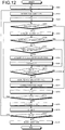
- FIG. 12 is a flowchart illustrating overview of processing executed by the direction determination unit 22 according to the third modified example of the first embodiment of the present invention, and is a flowchart illustrating overview of direction determination processing.
- the correlation value calculation unit 221 sets a pixel of interest as a standard pixel in the dir direction (step S302).
- the correlation value calculation unit 221 sets, as a standard pixel, a pixel being a pixel in the dir direction that is closest to the pixel of interest, and not being an isolated point pixel. Nevertheless, when all the pixels in the dir direction are isolated point pixels, the pixel of interest is set as a standard pixel.
- the correlation value calculation unit 221 determines whether the ith pixel is an isolated point pixel (step S304).
- step S304: Yes the direction determination unit 22 advances the processing to step S313 to be described later.
- step S304: No the direction determination unit 22 advances the processing to step S305 to be described later.
- step S305 the correlation value calculation unit 221 acquires the ith pixel value based on the RAW image obtained by acquiring the RAW image stored in the volatile memory 111, via the second external I/F unit 21, the first external I/F unit 115, and the bus 113 (step S305). In addition, the correlation value calculation unit 221 stores the acquired pixel value into the buffer 242 by copying the value as Pi.
- the correlation value calculation unit 221 determines whether the ith pixel is a standard pixel (step S306).
- step S306: Yes the direction determination unit 22 advances the processing to step S313 to be described later.
- step S306: No the direction determination unit 22 advances the processing to step S307 to be described later.
- step S307 based on the RTS noise information acquired from the RTS noise information recording unit 112b via the second external I/F unit 21, the first external I/F unit 115, and the bus 113, the correlation value calculation unit 221 determines whether RTS noise occurs in the standard pixel.
- the correlation value calculation unit 221 determines that there is a possibility that RTS noise occurs in the standard pixel (step S307: Yes)
- the direction determination unit 22 advances the processing to step S308 to be described later.
- the direction determination unit 22 advances the processing to step S310 to be described later.
- step S308 the correlation value calculation unit 221 acquires RTS_Value of the standard pixel from the RTS noise information acquired from the RTS noise information recording unit 112b via the second external I/F unit 21, the first external I/F unit 115, and the bus 113.
- the correlation value calculation unit 221 corrects Pi (step S309). More specifically, the correlation value calculation unit 221 corrects Pi by selecting, from Pi + RTS_Value, Pi, and Pi - RTS_Value, a value closest to the pixel value of the standard pixel decided in the aforementioned step S302, and replacing the value of Pi with the selected value. The influence to be exerted when RTS_Value occurs in the standard pixel can be thereby excluded.
- the correlation value calculation unit 221 determines whether there is a possibility that RTS noise occurs in the ith pixel in the dir direction (step S310).
- the direction determination unit 22 advances the processing to step S311 to be described later.
- the direction determination unit 22 advances the processing to step S313 to be described later.
- step S311 the correlation value calculation unit 221 acquires RTS_Value of the ith pixel from the RTS noise information acquired from the RTS noise information recording unit 112b via the second external I/F unit 21, the first external I/F unit 115, and the bus 113.
- the correlation value calculation unit 221 corrects the ith pixel value by selecting, from among Pi + RTS_Value, Pi, and Pi - RTS_Value that have been corrected in step 309, a value closest to the pixel value of the standard pixel, and substituting the selected value into Pi (step S312).
- the influence to be exerted when RTS noise occurs in the ith pixel can be thereby excluded.
- Steps S313 to S318 respectively correspond to the aforementioned steps S115 to step S120 in FIG. 6 .
- the direction determination unit 22 decides the pixel of interest as a standard pixel, and performs direction determination while excluding the influence of RTS noise in the standard pixel, according to whether there is a possibility that RTS noise occurs in the standard pixel. As a result, direction determination can be accurately performed on image data in which RTS noise occurs.
- the correlation value calculation unit 221 calculates a value obtained by adding RTS_Value to or subtracting RTS_Value from a pixel value.
- a value obtained by multiplying RTS_Value by a predetermined coefficient equal to or larger than 0 and smaller than 1 may be added or subtracted considering the distribution of RTS noise such as anoise.
- the fourth modified example of the first embodiment of the present invention has the same configuration as the imaging system 1 according to the aforementioned first embodiment, and differs only in processing executed by the direction determination unit. More specifically, the direction determination unit according to the fourth modified example of this first embodiment performs edge direction determination by excluding a pixel in which there is a possibility that RTS noise occurs, in each direction in which a correlation degree is to be calculated. Thus, processing executed by the direction determination unit according to the fourth modified example of this first embodiment will be described below.
- the same configurations as those in the imaging system 1 according to the aforementioned first embodiment are assigned the same sings, and the description thereof will be omitted.
- FIG. 13 is a flowchart illustrating overview of processing executed by the direction determination unit 22 according to the fourth modified example of the first embodiment of the present invention, and is a flowchart illustrating overview of direction determination processing.
- the correlation value calculation unit 221 determines whether there is a possibility that RTS noise occurs in the ith pixel (step S403).
- the direction determination unit 22 advances the processing to step S405 to be described later.
- the direction determination unit 22 advances the processing to step S404 to be described later.
- step S404 the correlation value calculation unit 221 acquires the ith pixel value based on the RAW image acquired from the volatile memory 111 via the second external I/F unit 21, the first external I/F unit 115, and the bus 113.
- the correlation value calculation unit 221 stores the acquired pixel value into the buffer 242 by copying the value in the variables P1 to P7.
- Steps S405 and S406 respectively correspond to the aforementioned steps S115 and S116 in FIG. 6 .
- the correlation value calculation unit 221 calculates an evaluation value ⁇ dir leading to a correlation degree, using only a pixel value of a pixel in which there is no possibility that RTS noise occurs that has been acquired in step S404. More specifically, the correlation value calculation unit 221 excludes, from the variables P1 to P7, a variable corresponding to a pixel in which there is a possibility that RTS noise occurs, and calculates, as the evaluation value ⁇ dir, any one of an absolute value of a difference between the minimum value and the maximum value in the respective pixel values of the remaining variables, respective standard deviations and dispersions of the variables P1 to P7, and an average value of absolute values of differences between the pixels.
- the correlation value calculation unit 221 may further exclude a variable corresponding to an isolated point pixel, and use the other variables for calculating ⁇ dir.
- the correlation value calculation unit 221 calculates, as ⁇ dir, a value having the lowest correlation.
- Steps S408 to S410 respectively correspond to the aforementioned steps S118 to step S120 in FIG. 6 .
- the direction determination unit 22 performs direction determination by excluding a pixel in which there is a possibility that RTS noise occurs, in each direction in which a correlation degree is to be calculated in the RAW image. As a result, direction determination can be accurately performed on image data in which RTS noise occurs.
- the fifth modified example of the first embodiment of the present invention has the same configuration as the imaging system 1 according to the aforementioned first embodiment, and differs only in processing executed by the direction determination unit. More specifically, the direction determination unit according to the fifth modified example of this first embodiment performs edge direction determination by excluding a pixel in which there is a possibility that RTS noise occurs, when the pixel is distant from a standard by a predetermined value or more, in each direction in which a correlation degree is to be calculated. Thus, processing executed by the direction determination unit according to the fifth modified example of this first embodiment will be described below. In addition, the same configurations as those in the imaging system 1 according to the aforementioned first embodiment are assigned the same sings, and the description thereof will be omitted.
- FIG. 14 is a flowchart illustrating overview of processing executed by the direction determination unit 22 according to the fifth modified example of the first embodiment of the present invention, and is a flowchart illustrating overview of direction determination processing.
- steps S501 to S505 respectively correspond to the aforementioned steps S201 to step S205 in FIG. 11 .
- step S506 the correlation value calculation unit 221 acquires RTS_Value of the ith pixel in the dir direction from the RTS noise information recording unit 112b via the second external I/F unit 21, the first external I/F unit 115, and the bus 113, and calculates a value obtained by multiplying the acquired RTS_Value by a predetermined coefficient, as a threshold value.
- the predetermined coefficient is preferably 1 or less, and is 0.5, for example.
- the correlation value calculation unit 221 determines whether an absolute value of a difference between Pi acquired in the aforementioned step S502 and the average value calculated in step S503 is larger than the threshold value calculated in step S506 ([average value - Pi] > threshold value) (step S507).
- the correlation value calculation unit 221 determines that an absolute value of a difference between Pi acquired in the aforementioned step S502 and the average value calculated in step S503 is larger than the threshold value calculated in step S506 (step S507: Yes)
- the direction determination unit 22 advances the processing to step S508 to be described later.
- step S507 when the correlation value calculation unit 221 determines that an absolute value of a difference between Pi acquired in the aforementioned step S502 and the average value calculated in step S503 is not larger than the threshold value calculated in step S506 (step S507: No), the direction determination unit 22 advances the processing to step S509 to be described later.
- step S508 the correlation value calculation unit 221 deletes Pi stored in step S502.
- Steps S509 and S510 respectively correspond to steps S115 and S116 in FIG. 6 .
- step S511 the correlation value calculation unit 221 calculates, as an evaluation value ⁇ dir, any one of an absolute value of a difference between the minimum value and the maximum value in the respective pixel values of the variables P1 to P7 that have remained after the processing in the aforementioned step S508, respective standard deviations and dispersions of the variables P1 to P7, and an average value of absolute values of differences between the pixels.
- Steps S512 to S514 respectively correspond to the aforementioned steps S118 to step S120 in FIG. 6 .
- the direction determination unit 22 determines that RTS noise occurs in the pixel, and performs direction determination by excluding the pixel value.
- direction determination can be accurately performed on image data in which RTS noise occurs.
- direction determination may be performed by uniformly excluding a pixel in which there is a possibility that RTS noise occurs (pixel having position information recorded in the RTS noise information recording unit 112b as a pixel in which there is a possibility that RTS noise occurs).
- a calculation amount can be thereby reduced as compared with the fifth modified example of the aforementioned first embodiment of the present invention.
- An imaging system according to this second embodiment differs from that according to the aforementioned first embodiment in the configuration of the imaging system 1. More specifically, the imaging system according to this second embodiment differs from that according to the aforementioned first embodiment in the configuration of an image processing apparatus. Thus, a configuration of an imaging system according to this second embodiment will be described below. In addition, the same configurations as those in the imaging system 1 according to the aforementioned first embodiment are assigned the same sings, and the description thereof will be omitted.
- FIG. 15 is a block diagram schematically illustrating a configuration of the imaging system according to the second embodiment of the present invention.
- An imaging system 1a illustrated in FIG. 15 includes an image processing apparatus 20a in place of the image processing apparatus 20 according to the aforementioned first embodiment.
- the image processing apparatus 20a includes an image processor 23a in place of the image processor 23 according to the aforementioned first embodiment.
- the image processor 23a includes an isolated point correction unit 26, an RTS noise correction unit 27, and a basic image processor 28.
- the isolated point correction unit 26 acquires isolated point position information from the isolated point position information recording unit 112d, and a RAW image from the volatile memory 111, via the second external I/F unit 21, the first external I/F unit 115, and the bus 113, and outputs image data in which an isolated point has been corrected, to the RTS noise correction unit 27, based on the acquired isolated point position information.
- FIG. 16 is a block diagram illustrating a functional configuration of the isolated point correction unit 26. As illustrated in FIG. 16 , the isolated point correction unit 26 includes a direction determination unit 261 and a correction unit 262.
- the direction determination unit 261 has a function similar to that of the aforementioned the direction determination unit 22, and determines a direction in which correlation is the highest, in a pixel value of a pixel of interest in the RAW image and pixel values of neighboring pixels of the pixel of interest.
- the correction unit 262 reduces noise by correcting noise in image data based on the determination result of the direction determination unit 261.
- the RTS noise correction unit 27 corrects RTS noise in the image data that has been corrected by the isolated point correction unit 26, and outputs the RTS noise to the basic image processor 28.
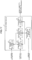
- FIG. 17 is a block diagram illustrating a functional configuration of the RTS noise correction unit 27.
- the RTS noise correction unit 27 includes an RTS noise pixel determination unit 271, a candidate value calculation unit 272, a random noise amount estimation unit 273, a representative value calculation unit 274, and a correction value calculation unit 275.
- the RTS noise pixel determination unit 271 acquires RTS noise information recorded in the RTS noise information recording unit 112b of the imaging apparatus 10, via the second external I/F unit 21, the first external I/F unit 115, and the bus 113, determines whether there is a possibility that RTS noise occurs in pixels on the acquired RAW image, and outputs the determination result to the candidate value calculation unit 272 and the representative value calculation unit 274.
- the RTS noise pixel determination unit 271 determines whether RTS noise information corresponding to the pixel is recorded in the RTS noise information recording unit 112b of the imaging apparatus 10, and outputs the RTS noise information (information indicating that there is RTS noise) if the RTS noise information is recorded. On the other hand, if the RTS noise information is not recorded in the RTS noise information recording unit 112b of the imaging apparatus 10, the RTS noise pixel determination unit 271 regards the pixel as a pixel in which RTS noise does not occur, and does not output RTS noise information.
- the candidate value calculation unit 272 calculates a plurality of candidate values of a correction amount for the pixel value of the pixel of interest, based on the pixel value of the pixel of interest in the RAW image, and the determination result of the RTS noise pixel determination unit 271, and outputs the pixel value of the pixel of interest in the RAW image, and the plurality of calculated candidate values to the representative value calculation unit 274, the random noise amount estimation unit 273, and the correction value calculation unit 275.
- the random noise amount estimation unit 273 acquires a random noise model recorded in the random noise model information recording unit 112c, via the second external I/F unit 21, the first external I/F unit 115, and the bus 113, and calculates a random noise amount according to the pixel value of the pixel of interest or a reference value in a RAW image in the vicinity of the pixel of interest, based on the acquired random noise model and the reference value calculated by the representative value calculation unit 274.
- the representative value calculation unit 274 calculates a representative value corresponding to a pixel value obtainable when RTS noise does not occur.
- the representative value calculation unit 274 outputs the pixel value of the pixel of interest in the RAW image, the plurality of candidate values, and the representative value calculated in the aforementioned processing, to the correction value calculation unit 275.
- FIG. 18 is a block diagram illustrating a functional configuration of the representative value calculation unit 274. As illustrated in FIG. 18 , the representative value calculation unit 274 includes a direction determination unit 274a and a representative value decision unit 274b.
- the direction determination unit 274a has a function similar to that of the aforementioned the direction determination unit 22, and determines a direction in which correlation is the highest, in a pixel value of a pixel of interest in the RAW image and pixel values of neighboring pixels of the pixel of interest.
- the representative value decision unit 274b decides a representative value corresponding to a pixel value obtainable when RTS noise does not occur.
- the correction value calculation unit 275 corrects the pixel value of the pixel of interest based on the plurality of candidate values calculated by the candidate value calculation unit 272. More specifically, based on the pixel value of the pixel of interest in the RAW image, the plurality of candidate values calculated by the candidate value calculation unit 272, and the representative value calculated by the representative value calculation unit 274, the correction value calculation unit 275 calculates a pixel value in which RTS noise has been corrected, and outputs the pixel value to the basic image processor 28.
- the correction value calculation unit 275 corrects the pixel value of the pixel of interest based on a candidate value that generates a correction result closest to the representative value calculated by the representative value calculation unit 274, among the plurality of candidate values calculated by the candidate value calculation unit 272.
- the correction value calculation unit 275 directly outputs the pixel value of the pixel of interest in the RAW image.
- the basic image processor 28 Based on a determination result of the direction determination unit 22, the basic image processor 28 performs predetermined image processing on the corrected image data input from the RTS noise correction unit 27, and outputs the image data to the display device 30.
- the predetermined image processing basic image processing is performed including at least optical black reduction processing and white balance adjustment processing, and including synchronization processing of image data, color matrix calculation processing, ⁇ -correction processing, color reproduction processing, edge enhancement processing, noise reduction processing, and the like when the image sensor 105 has the Bayer array.
- the basic image processor 28 performs image processing for reproducing a natural image, based on preset parameters of each type of image processing.
- the parameters of each type of image processing include values of contrast, sharpness, saturation, white balance, and gradation.
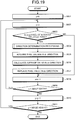
- FIG. 19 is a flowchart illustrating overview of processing executed by the isolated point correction unit 26, is a flowchart illustrating overview of isolated point correction processing.
- the isolated point correction unit 26 determines whether a pixel of interest in a coordinate (x, y) is an isolated point (step S603).
- the isolated point correction unit 26 advances the processing to step S604 to be described later.
- the isolated point correction unit 26 advances the processing to step S608 to be described later.
- step S604 the direction determination unit 261 executes the direction determination processing of any of the aforementioned first embodiment and the second to fifth modified examples of the aforementioned first embodiment.
- the description of the direction determination processing will be omitted.
- the direction determination unit 261 calculates an average value by excluding a pixel value of an isolated point pixel.
- the correction unit 262 acquires, from the buffer 242, all the pixel values in the dir direction determined by the direction determination unit 261 (step S605). In addition, the correction unit 262 stores the acquired pixel values into the buffer 242 by copying the values in the variables P1 to P7.
- the correction unit 262 excludes an isolated point pixel from the variables P1 to P7, and calculates an average value in the dir direction using pixel values of the remaining pixels (step S606). In addition, in place of an average value, the correction unit 262 may calculate any of a weighted average, a mode value, and a median value of the variables P1 to P7.
- the correction unit 262 corrects the isolated point pixel by replacing a pixel value in the dir direction by placing the pixel value of the pixel of interest in the coordinate (x, y) stored in the buffer 242, with the average value calculated in step S606 (step S607).
- step S609: Yes when the counter x is smaller than a width of an image corresponding to image data (step S609: Yes), the isolated point correction unit 26 returns the processing to step S603. In contrast to this, when the counter x is not smaller than a width of an image corresponding to image data (step S609: No), the isolated point correction unit 26 advances the processing to step S610.
- step S611: Yes when the counter y is smaller than a height of an image corresponding to image data (step S611: Yes), the isolated point correction unit 26 returns the processing to step S602. In contrast to this, when the counter y is not smaller than a height of an image corresponding to image data (step S611: No), the isolated point correction unit 26 ends this processing.
- the isolated point correction unit 26 removes an isolated point, and generates image data in which an edge direction has been corrected, and outputs the image data to the RTS noise correction unit 27.
- FIG. 20 is a flowchart illustrating overview of processing executed by the RTS noise correction unit 27, and is a flowchart illustrating overview of RTS noise correction processing.
- the RTS noise correction unit 27 first sets a pixel of interest for sequentially performing processing in steps S702 to S705 to be described later (step S701). In addition, the RTS noise correction unit 27 sequentially allocates, as an index, an integer larger than 0 as 1, 2, 3, and so on, to each pixel in the RAW image, in a raster order starting from the upper left toward the lower right. Next, the RTS noise correction unit 27 increments a counter of the buffer 242 by 1, each time step S701 is executed (counter is reset to 0 at a time point when the processing in FIG. 20 is started). The RTS noise correction unit 27 sets, as a pixel of interest, a pixel to which an index indicated by the counter is allocated.
- step S701 when step S701 is initially executed by the RTS noise correction unit 27, the RTS noise correction unit 27 increments the counter reset to 0, by 1. Thus, the counter indicates 1, and an upper left pixel becomes a pixel of interest.
- the RTS noise correction unit 27 executes the processing in step S701 twice (the second time), the counter indicates 2. Thus, a pixel on the right side of the upper left pixel becomes a pixel of interest.
- the RTS noise pixel determination unit 271 acquires RTS noise information recorded in the RTS noise information recording unit 112b of the nonvolatile memory 112 of the imaging apparatus 10, via the second external I/F unit 21, the first external I/F unit 115, and the bus 113, and determines, based on the acquired RTS noise information, whether there is a possibility that RTS noise occurs in the pixel of interest (step S702). In other words, the RTS noise pixel determination unit 271 determines whether position information of a share pixel block including a pixel of interest is included in the RTS noise information.
- the RTS noise pixel determination unit 271 determines whether position information of the share pixel block including the pixel of interest is included in the RTS noise information as a share pixel block in which there is a possibility that RTS noise occurs.
- the RTS noise correction unit 27 advances the processing to step S703 to be described later.
- the RTS noise correction unit 27 advances the processing to step S706 to be described later.
- the RTS noise pixel determination unit 271 determines that there is no possibility that RTS noise occurs in the pixel of interest, the RTS noise pixel determination unit 271 directly outputs the pixel value of the pixel of interest in the RAW image to the representative value calculation unit 274 as a corrected pixel value.
- the candidate value calculation unit 272 calculates a plurality of candidate values of a correction amount for correcting RTS noise. More specifically, based on RTS_Value corresponding to the pixel of interest (included in RTS noise information included in RTS noise output from the RTS noise pixel determination unit 271), the candidate value calculation unit 272 sets, as candidate values, all values equal to or larger than 0 and equal to smaller than RTS_Value that can be taken as a pixel value (when only integers can be taken as a RAW image, all integers equal to or larger than 0 and equal to or smaller than RTS_Value).
- the candidate value calculation unit 272 may cause RTS noise information to have RTS_Values of respective amplifier gain values that can be preset, and use RTS_Value according to the set amplifier gain values.
- the candidate value calculation unit 272 may select a predetermined number of values from among the values equal to or larger than 0 and equal to or smaller than RTS_Value that can be taken as a pixel value, and sets the selected values as candidate values.
- the representative value calculation unit 274 executes representative value calculation processing of calculating a representative value (pixel value in the RAW image that is predicted when RTS noise does not occur in the pixel of interest)(step S704).
- a representative value calculation unit 323 may include a pixel in which there is a possibility that RTS noise occurs.
- FIG. 21 is a flowchart illustrating overview of the representative value calculation processing in step S704 in FIG. 20 .
- the direction determination unit 274a first executes direction determination processing in a range centered on the pixel of interest (step S710). In this case, the direction determination unit 274a executes the direction determination processing of any of the aforementioned first embodiment and the second to fifth modified examples of the aforementioned first embodiment. Thus, detailed description of the direction determination processing will be omitted.
- the representative value decision unit 274b acquires pixel values in the dir direction obtained through the direction determination, from the RAW image stored in the volatile memory 111, via the second external I/F unit 21, the first external I/F unit 115, and the bus 113 (step S711). In addition, the representative value decision unit 274b stores all the acquired pixels values in the dir direction into the buffer 242 by copying the values in the variables P1 to P7.
- the representative value decision unit 274b calculates, as a representative value, an average value of the respective pixel values of the variables P1 to P7 stored in the buffer 242 (step S712).
- the representative value decision unit 274b may exclude a pixel value of the pixel in which there is a possibility that RTS noise occurs, and calculate, as a representative value, an average value of pixel values of the remaining pixels.
- the representative value decision unit 274b may calculate, as a representative value, any of a weighted average, a mode value, and a median value of the respective pixel values of the variables P1 to P7.
- the RTS noise correction unit 27 returns the processing to a main routine of FIG. 20 .
- step S705 the description subsequent to step S705 will be continued.
- step S705 based on the plurality of candidate values calculated by the candidate value calculation unit 272 in the aforementioned step S703, and the representative value calculated by the representative value calculation unit 274 in the aforementioned step S704, the correction value calculation unit 275 executes correction value calculation processing of calculating a pixel value of a RAW pixel in which RTS noise in the pixel of interest has been corrected.
- FIG. 22 is a flowchart illustrating overview of the correction value calculation processing in step S705 in FIG. 20 .
- the correction value calculation unit 275 first determines whether the maximum value of the candidate values is equal to or larger than a threshold value (step S721).
- the threshold value is set according to the following formula (1): random noise amount ⁇ Rm
- Rm denotes a predetermined coefficient.
- Rm is decided according to the visuality degree of RTS noise with respect to random noise.
- the value of Rm is preferably around 2.
- the correction value calculation unit 275 compares an absolute value of ⁇ with one or more candidate values calculated by the candidate value calculation unit 272 in the aforementioned step S703 in FIG. 20 , selects a candidate value closest to the absolute value of ⁇ , and sets the candidate value as ⁇ . In addition, if there is a plurality of candidate values closest to the absolute value of ⁇ , the correction value calculation unit 275 selects, as ⁇ , the smallest candidate value of the plurality of candidate values, for preventing excess correction.
- the correction value calculation unit 275 corrects the pixel value of the pixel of interest in the RAW image by bringing the pixel value closer in the representative value direction by ⁇ , according to the following formulae (3) and (4), and outputs the corrected pixel value of the pixel of interest to the basic image processor 28.
- the RTS noise correction unit 27 returns the processing to the main routine of FIG. 20 .
- the correction value calculation unit 275 calculates ⁇ , and selects the smallest candidate value of the plurality of candidate values.
- the correction value calculation unit 275 may calculate values obtained by individually adding or subtracting each of the plurality of candidate values to or from the pixel value of the pixel of interest in the RAW image, and select the closest representative value among a plurality of added or subtracted values obtained by the calculation.
- the correction value calculation unit 275 may use other calculation and comparison methods as long as the same result is obtained.
- the correction value calculation unit 275 executes processing equivalent to processing of calculating, as a corrected pixel value of the pixel of interest, a value obtained by clipping a representative value into a value equal to or larger than the pixel value of the pixel of interest in the RAW image - RTS_Value, and equal to or smaller than the pixel value of the pixel of interest in the RAW image + RTS_Value.
- step S723 the correction value calculation unit 275 directly outputs the pixel value of the pixel of interest in the RAW image to the basic image processor 28.
- step S723 the RTS noise correction unit 27 returns the processing to the main routine of FIG. 20 .
- step S706 will be continued.
- step S706 the RTS noise correction unit 27 determines whether the processing in the aforementioned steps S701 to S705 has ended for all the pixels (step S706). When the RTS noise correction unit 27 determines that the aforementioned processing has ended for all the pixels (step S706: Yes), the RTS noise correction unit 27 ends this processing. In contrast to this, when the RTS noise correction unit 27 determines that the aforementioned processing has not ended for all the pixels (step S706: No), the RTS noise correction unit 27 returns the processing to the aforementioned step S701.
- direction determination can be accurately performed on image data.
- noise reduction e.g., isolated point reduction, blinking defective noise reduction, random noise reduction, etc.
- noise reduction can be performed so as to generate a high-quality image without feeling of strangeness at an edge portion or the like.
- isolated point reduction or blinking defective noise reduction is performed using a direction determination result.
- the present invention can be applied to various types of noise reduction such as random noise reduction.
- various types of noise reduction such as random noise reduction are only required to be executed so as to increase correlation of a pixel value in a direction indicated by the direction determination result.
- An imaging system according to this third embodiment differs from that according to the aforementioned second embodiment in the configuration of the imaging system 1a. More specifically, the imaging system according to this third embodiment differs from that according to the aforementioned first embodiment in the configuration of an image processing apparatus. Thus, a configuration of the imaging system according to this third embodiment will be described below. In addition, the same configurations as those in the imaging system 1 according to the aforementioned first embodiment are assigned the same sings, and the description thereof will be omitted.
- FIG. 23 is a block diagram schematically illustrating a configuration of the imaging system according to the third embodiment of the present invention.
- An imaging system 1b illustrated in FIG. 23 includes an image processing apparatus 20b in place of the image processing apparatus 20a according to the aforementioned second embodiment.
- the image processing apparatus 20b includes an image processor 23b in place of the image processor 23a according to the aforementioned second embodiment.
- the image processor 23b includes a synchronization processor 29 and the basic image processor 28.
- FIG. 24 is a block diagram illustrating a functional configuration of the synchronization processor 29. As illustrated in FIG. 24 , the synchronization processor 29 includes a direction determination unit 291 and an interpolation processor 292.
- the direction determination unit 291 has a function similar to that of the aforementioned the direction determination unit 22, and determines a direction in which correlation is the highest, in a pixel value of a pixel of interest in the RAW image and pixel values of neighboring pixels of the pixel of interest.
- the interpolation processor 292 Based on the determination result of the direction determination unit 291, the interpolation processor 292 assumes that an edge continues in a direction of the direction determination result in the RAW image data, and interpolates colors other than the colors of the color filters of the pixel of interest, to generate an RGB image.
- FIG. 25 is a flowchart illustrating overview of processing executed by the synchronization processor 29, and is a flowchart illustrating overview of synchronization processing.
- step S803: Yes when the pixel of interest in the coordinate (x, y) is a G pixel (step S803: Yes), the synchronization processor 29 advances the processing to step S808 to be described later. In contrast to this, when the pixel of interest in the coordinate (x, y) is not a G pixel (step S803: No), the synchronization processor 29 advances the processing to step S804 to be described later.
- step S804 the direction determination unit 291 executes the direction determination processing of any of the aforementioned first embodiment and the second to fifth modified examples of the aforementioned first embodiment.
- the direction determination unit 291 performs direction determination processing using a pixel value of a pixel in which a color filter having the largest influence on resolution is arranged, such as, for example, a pixel value of a G pixel.
- NBI narrow band imaging
- direction determination processing is performed using a pixel in which a color filter having the largest influence on resolution is arranged, such as, for example, a B pixel.
- the direction determination unit 291 may perform direction determination processing using a pixel value of a G pixel, a pixel value of an R pixel in which an R filter is arranged, and a pixel value of a B pixel in which a B filter is arranged, similarly to the direction determination processing of any of the aforementioned first embodiment and the second to fifth modified examples of the aforementioned first embodiment.
- the direction determination processing executed by the direction determination unit 291 corresponds to the direction determination processing of any of the aforementioned first embodiment and the second to fifth modified examples of the aforementioned first embodiment.
- the description of the direction determination processing will be omitted in this third embodiment.
- the interpolation processor 292 acquires all the pixel values in the dir direction determined by the direction determination unit 291, from the RAW image stored in the volatile memory 111, via the second external I/F unit 21, the first external I/F unit 115, and the bus 113 (step S805). In this case, the interpolation processor 292 stores the pixel values in the dir direction acquired from the volatile memory 111, into the buffer 242 by copying the values in the variables P1 to P7.
- the interpolation processor 292 calculates an average value in the dir direction, using the respective pixel values of the variables P1 to P7 stored in the buffer 242 (step S806). In addition, in place of an average value, the interpolation processor 292 may calculate, as an average value in the dir direction, any of a weighted average, a mode value, and a median value of the variables P1 to P7.
- the interpolation processor 292 interpolates the average value calculated in step S806, as a G component in the coordinate (x, y) stored in the buffer 242 (step S807) .
- step S808: Yes when the pixel of interest in the coordinate (x, y) is an R pixel (step S808: Yes), the synchronization processor 29 advances the processing to step S812 to be described later. In contrast to this, when the pixel of interest in the coordinate (x, y) is not an R pixel (step S808: No), the synchronization processor 29 advances the processing to step S809 to be described later.
- step S809 the interpolation processor 292 acquires, via the second external I/F unit 21, the first external I/F unit 115, and the bus 113, pixel values of R pixels surrounding the pixel of interest in the coordinate (x, y), from the RAW image stored in the volatile memory 111.
- the interpolation processor 292 calculates a weighted average of the pixel values of R pixels surrounding the pixel of interest in the coordinate (x, y) that have been acquired in step S809 (step S810).
- the interpolation processor 292 calculates the weighted average by applying a filter of allocating a larger weight to a pixel value of an R pixel closer to the coordinate (x, y), to R pixels within 5 ⁇ 5 pixels.
- the interpolation processor 292 interpolates the weighted average calculated in step S810, as an R component in the coordinate (x, y) stored in the buffer 242 (step S811).
- step S812: Yes when the pixel of interest in the coordinate (x, y) is a B pixel (step S812: Yes), the synchronization processor 29 advances the processing to step S816 to be described later. In contrast to this, when the pixel of interest in the coordinate (x, y) is not a B pixel (step S812: No), the synchronization processor 29 advances the processing to step S813 to be described later.
- step S813 the interpolation processor 292 acquires, via the second external I/F unit 21, the first external I/F unit 115, and the bus 113, pixel values of B pixels surrounding the pixel of interest in the coordinate (x, y), from the RAW image stored in the volatile memory 111.
- the interpolation processor 292 calculates a weighted average of the pixel values of B pixels surrounding the pixel of interest in the coordinate (x, y) that have been acquired in step S813 (step S814).
- the interpolation processor 292 calculates the weighted average by applying a filter of allocating a larger weight to a pixel value of a B pixel closer to the coordinate (x, y), to B pixels within 5 ⁇ 5 pixels.
- the interpolation processor 292 interpolates the weighted average calculated in step S814, as a B component in the coordinate (x, y) stored in the buffer 242 (step S815).
- step S817: Yes when the counter x is smaller than a width of an image corresponding to image data (step S817: Yes), the interpolation processor 292 returns the processing to step S803. In contrast to this, when the counter x is not smaller than a width of an image corresponding to image data (step S817: No), the interpolation processor 292 advances the processing to step S818.
- step S819: Yes when the counter y is smaller than a height of an image corresponding to image data (step S819: Yes), the interpolation processor 292 returns the processing to step S802. In contrast to this, when the counter y is not smaller than a height of an image corresponding to image data (step S819: No), the interpolation processor 292 ends this processing.
- the basic image processor 28 may perform edge enhancement that is based on the direction determination result, on an edge component that is based on the direction determination result of the aforementioned synchronization processor 29, by performing addition to image data through coring processing or gain multiplication processing.
- a method 1 is a method in which the basic image processor 28 generates an edge component that is based on the direction determination result, by subtracting an image obtained by applying a lowpass filter to an RGB image, from an RGB image having been subjected to interpolation processing in the above processing.
- a method 2 is a method in which the basic image processor 28 generates an edge component that is based on the direction determination result, by extracting edge components in a plurality of directions by applying a filter (e.g., differentiation filter, etc.) that can extract edges in a plurality of directions, around a pixel of interest, and calculating an edge component in a direction intersecting with the direction determination result of the direction determination unit 291.
- a filter e.g., differentiation filter, etc.
- a method 3 is a method in which the basic image processor 28 generates an edge component that is based on the direction determination result, by extracting edge components by applying a filter (e.g., Laplacian filter, etc.) that can extract edges in a plurality of directions, around a pixel of interest, and based on the direction determination result of the direction determination unit 291, performing smoothing in the direction.
- a filter e.g., Laplacian filter, etc.
- the basic image processor 28 performs edge enhancement that is based on the direction determination result, using the direction determination result of the aforementioned synchronization processor 29, and any of the aforementioned methods 1 to 3.
- direction determination can be accurately performed on image data in which blinking defective noise having pixel values varying within a certain range occurs, such as RTS noise.
- a high-resolution image can be generated by using the present invention for interpolation processing (synchronization processing, etc.) and edge extraction processing.
- the image processing apparatus is provided separately from the imaging apparatus. Nevertheless, in this fourth embodiment, an image processing apparatus is provided in an imaging apparatus main body.
- the same configurations as those in the imaging systems according to the aforementioned first to third embodiments are assigned the same sings, and the description thereof will be omitted.
- FIG. 27 is a block diagram schematically illustrating a configuration of the imaging system according to the fourth embodiment of the present invention.
- An imaging system 2 illustrated in FIG. 27 includes a main body unit 3, and a lens unit 4 detachably-connectable to the main body unit 3.
- the main body unit 3 includes the shutter 103, the image sensor 105, the analog processor 106, the A/D converter 107, the operating unit 108, the memory I/F unit 109, the recording medium 110, the volatile memory 111, the nonvolatile memory 112, the bus 113, the imaging controller 114, an AE processor 116, an AF processor 117, an external I/F unit 118, a display unit 119, a driver 120, and an image processor 32.
- the driver 120 drives the shutter 103 under the control of the imaging controller 114.
- the AE processor 116 acquires image data stored in the volatile memory 111, via the bus 113, and sets an exposure condition used in performing still image capturing or moving image capturing, based on the acquired image data. More specifically, the AE processor 116 calculates luminance from the image data, and performs automatic exposure (AutoExposure) of the imaging system 2 by deciding, for example, a diaphragm value, an exposure time, ISO sensitivity, and the like, based on the calculated luminance.
- AutoExposure automatic exposure
- the AF processor 117 acquires the image data stored in the volatile memory 111, via the bus 113, and adjusts autofocus of the imaging system 2 based on the acquired image data. For example, the AF processor 117 extracts a signal having a high-frequency component, from the image data, and adjusts autofocus of the imaging system 2 by deciding focusing evaluation of the imaging system 2 by performing AutoFocus (AF) calculation processing on the signal having a high-frequency component.
- the autofocus adjustment method of the imaging system 2 may acquire a phase difference signal in the image sensor 105.
- the external I/F unit 118 can perform, for example, reading and writing of data in various blocks in the main body unit 3, and control using a dedicated command or the like.
- the external I/F unit 118 is an interface that can control various blocks in the main body unit 3 by connecting to an external device such as a dedicated circuit and a personal computer (PC) on which an FPGA, a DSP, a GPU, or the like is mounted.
- PC personal computer
- the display unit 119 is formed by using a display panel having a liquid crystal, organic Electro Luminescence (EL), or the like.
- the display unit 119 displays an image corresponding to image data generated by the image sensor 105.
- the image processor 32 includes the direction determination unit 22, the isolated point correction unit 26, the RTS noise correction unit 27, and the basic image processor 28.
- the lens unit 4 forms a subject image condensed from a predetermined viewing field region, on the image sensor 105.
- the lens unit 4 includes the optical system 101 the diaphragm 102, and the driver 104.
- FIG. 28 is a flowchart illustrating overview of processing executed by the imaging system 2.
- the imaging controller 114 first initializes the imaging system 2 (step S901). More specifically, the imaging controller 114 performs initialization of setting a recording flag indicating that a moving image is being recorded, to an off state.
- the recording flag is a flag set to an on state during the capturing of a moving image, and set to the off state when a moving image is not being captured, and is stored in the volatile memory 111.
- step S902 when a moving image button of the operating unit 108 is pressed (step S902: Yes), the imaging controller 114 inverts the recording flag in the on state that indicates that a moving image is being recorded (step S903), and the imaging controller 114 determines whether the imaging system 2 is recording a moving image (step S904). More specifically, the imaging controller 114 determines whether the recording flag stored in the volatile memory 111 is in the on state.
- step S904: Yes the imaging system 2 advances the processing to step S905 to be described later.
- step S906 when it is determined by the imaging controller 114 that the imaging system 2 is not recording a moving image
- step S905 the imaging controller 114 generates a moving image file for chronologically recording image data onto the recording medium 110.
- the imaging system 2 advances the processing to step S906 to be described later.
- step S902 When the moving image button of the operating unit 108 is not pressed in step S902 (step S902: No), the imaging system 2 advances the processing to step S906.
- the imaging controller 114 determines whether the imaging system 2 is recording a moving image (step S906). When it is determined by the imaging controller 114 that the imaging system 2 is recording a moving image (step S906: Yes), the imaging system 2 advances the processing to step S917 to be described later. In contrast to this, when it is determined by the imaging controller 114 that a moving image is not being recorded (step S906: No), the imaging system 2 advances the processing to step S907 to be described later.
- step S907 When a playback button of the operating unit 108 is pressed in step S907 (step S907: Yes), the imaging system 2 causes the display unit 119 to play back and display an image corresponding to image data recorded on the recording medium 110 (step S908). After step S908, the imaging system 2 advances the processing to step S909 to be described later.
- step S907 When the playback button of the operating unit 108 is not pressed in step S907 (step S907: No), the imaging system 2 advances the processing to step S909.
- step S909 Yes
- the imaging system 2 executes setting processing of performing various setting (step S910). After step S910, the imaging system 2 advances the processing to step S911 to be described later.
- step S909 When the menu button of the operating unit 108 is not pressed in step S909 (step S909: No), the imaging system 2 advances the processing to step S911.
- step S911 When a release button of the operating unit 108 shifts from the off state a 1st state in step S911 (step S911: Yes), the imaging controller 114 causes the AE processor 116 to execute the AE processing of adjusting exposure, and causes the AF processor 117 to execute the AF processing of adjusting focus (step S912). After that, the imaging system 2 advances the processing to step S924 to be described later.
- step S911 When the release button of the operating unit 108 does not shift from the off state to the 1st state in step S911 (step S911: No), the imaging system 2 advances the processing to step S913.
- the imaging controller 114 executes image capturing using a mechanical shutter (step S914). More specifically, the imaging controller 114 causes the image sensor 105 to execute image capturing, by controlling the shutter 103.
- the image processor 32 executes image processing of performing direction determination on image data generated by the image sensor 105, correcting RTS noise, and then, performing predetermined processing (step S915).
- image processing of performing direction determination on image data generated by the image sensor 105, correcting RTS noise, and then, performing predetermined processing (step S915).
- the imaging controller 114 records the image data on which the image processing has been performed by the image processor 32, onto the recording medium 110 (step S916). After step S916, the imaging system 2 advances the processing to step S924 to be described later.
- step S913 When the release button of the operating unit 108 does not shift to the 2nd state in step S913 (step S913: No), the imaging system 2 advances the processing to step S917.
- the imaging controller 114 causes the AE processor 116 to execute the AE processing of adjusting exposure (step S917), and causes the AF processor 117 to execute the AF processing of adjusting focus (step S918) .
- the imaging controller 114 causes the image sensor 105 to execute so-called image capturing using an electrical shutter for electrically controlling an exposure time via the driver 120 (step S919).
- Image data generated by the image sensor 105 by the image capturing using the electrical shutter is output to the volatile memory 111 via the analog processor 106, the A/D converter 107, and the bus 113.
- the image processor 32 executes image processing similar to that in step S915 (step S920). In addition, the details of the image processing will be described later.
- the imaging system 2 causes the display unit 119 to display a live view image corresponding to the image data generated by the image sensor 105 by the image capturing using the electrical shutter (step S921).
- step S922 when the imaging system 2 is recording a moving image (step S922: Yes), the imaging controller 114 causes an image compression expansion unit (not illustrated) to compress the image data in a recording format set in the setting processing in step S910, and records the compressed image data into the moving image file created in the recording medium 110, as a moving image (step S923).
- step S923 the imaging system 2 advances the processing to step S924.
- step S922 When the imaging system 2 is not recording a moving image in step S922 (step S922: No), the imaging system 2 advances the processing to step S924.
- step S924: Yes when the power button of the operating unit 108 is pressed, and the power of the imaging system 2 is set to the off state (step S924: Yes), the imaging system 2 ends this processing. In contrast to this, when the power of the imaging system 2 is not in the off state (step S924: No), the imaging system 2 returns the processing to step S902.
- FIG. 29 is a flowchart illustrating overview of the image processing.
- the direction determination unit 22 first executes direction determination processing of determining an edge, on the image data generated by the image sensor 105 (step S951).
- the direction determination processing corresponds to any of the direction determination processing executed by the direction determination unit 22 in the aforementioned first embodiment and the second to fifth modified examples of the aforementioned first embodiment. Thus, the description thereof will be omitted.
- the isolated point correction unit 26 executes, on the image data, isolated point correction processing of correcting an isolated point in the image data (step S952).
- the isolated point correction processing corresponds to the isolated point correction processing executed by the isolated point correction unit 26 in the aforementioned second embodiment. Thus, the description thereof will be omitted.
- the RTS noise correction unit 27 executes, on the image data, RTS noise correction processing of correcting RTS noise in the image data (step S953).
- the RTS noise correction processing corresponds to the RTS noise correction processing executed by the RTS noise correction unit 27 in the aforementioned second embodiment. Thus, the description thereof will be omitted.
- the basic image processor 28 executes basic image processing on the image data in which RTS noise has been corrected by the RTS noise correction unit 27 (step S954). After step S954, the imaging system 2 returns the processing to a main routine of FIG. 28 .
- an effect similar to that in the aforementioned first embodiment is brought about, and edge direction determination can be accurately performed on image data in which blinking defective noise having values varying at random within a predetermined range occurs, such as RTS noise.
- correction processing of correcting RTS noise, synchronization processing, isolated point correction processing of excluding an isolated point, and the like are performed based on the determination result of the direction determination unit.
- noise reduction processing of suppressing or reducing noise included in image data, resizing processing of expanding or contracting an image, and the like may be performed based on the determination result of the direction determination unit.
- the RTS noise information recording unit, the random noise model information recording unit, and the isolated point position information recording unit are provided in the imaging apparatus. Nevertheless, they may be provided in the aforementioned image processing apparatus.
- the RTS noise information recording unit, the random noise model information recording unit, and the isolated point position information recording unit may be provided in a server that can perform interactive communication via a network, so that the RTS noise information, the random noise model information recording unit, and the isolated point position information recording unit may be acquired via the network.
- the RTS noise information recording unit, the random noise model information recording unit, and the isolated point position information recording unit may be provided in a detachable device including the image sensor.
- the present invention is not limited to the aforementioned embodiments, and it should be appreciated that various modifications and applications can be made within the scope of the present invention.
- the present invention can be applied to any device that can capture an image of a subject, such as an imaging apparatus that captures an image of a subject through an optical equipment.
- an imaging apparatus include a portable device including an image sensor in a mobile phone and a smartphone, a video camera, an endoscope, a monitoring camera, and microscope.
- the present invention can be applied to image data other than image data used for display or recording.
- the present invention can be applied to image data such as image data in an OB region, or image data in a region outside an image circle having an optically-unassured design.
- a method of each processing performed by the image processing apparatus in the aforementioned embodiments can be stored as a program that can be executed by a control unit such as a CPU.
- the processing can be delivered with being stored in a storage medium of an external storage device such as a memory card (ROM card, RAM card, etc.), a magnetic disc (floppy disk, hard disc, etc.), an optical disk (CD-ROM, DVD, etc.), a semi-conductor memory, and the like.
- the control unit such as a CPU can execute the aforementioned processing by reading a program stored in a storage medium of the external storage device, and an operation being controlled according to the read program.
- the present invention is not limited to the aforementioned embodiments and the modified examples in an unchanged state.
- the present invention can be embodied by modifying components without departing from the scope of the invention.
- various inventions can be formed by appropriately combining a plurality of components disclosed in the aforementioned embodiments. For example, several components may be deleted from all the components described in the aforementioned embodiments and the modified examples. Furthermore, the components described in the embodiments and the modified examples may be appropriately combined.
Landscapes
- Engineering & Computer Science (AREA)
- Multimedia (AREA)
- Signal Processing (AREA)
- Physics & Mathematics (AREA)
- General Physics & Mathematics (AREA)
- Theoretical Computer Science (AREA)
- Transforming Light Signals Into Electric Signals (AREA)
- Image Processing (AREA)
- Studio Devices (AREA)
- Picture Signal Circuits (AREA)
Abstract
Description
- The present invention relates to an image processing apparatus, an image processing method, and a program that perform direction determination on image data in which blinking defective noise having pixel values varying within a certain range occurs, such as RTS noise that occurs in an image sensor including a plurality of pixels arranged in a two-dimensional matrix.
- For reducing noise that occurs in image data generated by an image sensor such as a complementary metal oxide semiconductor (CMOS), there has been recently known a technique of reducing noise by determining the direction of an edge based on a pixel value of a pixel of interest in an image corresponding to image data, and pixel values of neighboring pixels surrounding the pixel of interest, and performing noise reduction processing using the determination result (refer to Patent Literature 1).
- Patent Literature 1:
JP 2014-225787 A - Nevertheless, in the
aforementioned Patent Literature 1, if blinking defective noise having pixel values varying within a certain range occurs in image data, such as random telegraph signal (RTS) noise, pixel values vary within the range of a blinking defective noise level. Thus, there is such a problem that edge direction determination cannot be accurately performed. As a result, theaforementioned Patent Literature 1 has such a problem that noise occurring in image data fails to be reduced due to erroneous determination of the edge direction, and image quality significantly deteriorates. - The present invention has been contrived in view of the foregoing, and the object of the present invention to provide an image processing apparatus, an image processing method, and a program that can accurately perform direction determination on image data in which blinking defective noise having pixel values varying within a certain range occurs, such as RTS noise.
- To solve the above-described problem and achieve the object, an image processing apparatus according to the present invention is an image processing apparatus for performing image processing on image data including blinking defective noise that has been generated by an image sensor including pixels arranged in a two-dimensional matrix, the pixels being configured to receive light from outside and to generate a signal according to a light receiving amount, and readout circuits configured to read out the signal as a pixel value, and includes: an acquisition unit configured to acquire noise information including position information of a pixel in which there is a possibility that blinking defective noise attributed to the readout circuit occurs; a direction determination unit configured to determine, based on the noise information acquired by the acquisition unit, and pixel values of neighboring pixels surrounding a pixel of interest in an image corresponding to the image data, a direction in which pixel values having highest correlation with a pixel value of the pixel of interest are consecutively arrayed; and an image processor configured to perform image processing on the image data based on a determination result of the direction determination unit.
- Moreover, in the above-described image processing apparatus according to the present invention, the noise information includes information in which the position information and feature data related to the blinking defective noise attributed to the readout circuit are associated.
- Moreover, in the above-described image processing apparatus according to the present invention, the direction determination unit determines the direction based on the feature data, the pixel value of the pixel of interest, and the pixel values of the neighboring pixels.
- Moreover, in the above-described image processing apparatus according to the present invention, the direction determination unit determines the direction using any one value of the pixel value of the pixel of interest, a value obtained by adding the feature data to the pixel value of the pixel of interest, and a value obtained by subtracting the feature data from the pixel value of the pixel of interest.
- Moreover, in the above-described image processing apparatus according to the present invention, in a case of determining correlation in each direction in the pixel of interest with respect to the image, the direction determination unit decides a standard pixel from the pixel of interest or the neighboring pixels, and when there is a possibility that the blinking defective noise occurs in the standard pixel, determines the direction by correcting pixel values of pixels other than the standard pixel using the feature data.
- Moreover, in the above-described image processing apparatus according to the present invention, the feature data is any of a noise level of the blinking defective noise and a value calculated based on the noise level.
- Moreover, in the above-described image processing apparatus according to the present invention, the direction determination unit determines the direction by excluding a pixel in which there is a possibility that the blinking defective noise occurs, based on the position information.
- Moreover, in the above-described image processing apparatus according to the present invention, the image processor performs image processing of removing noise in the pixel value of the pixel of interest so as to increase correlation of a pixel value of a pixel in the direction determined by the direction determination unit.
- Moreover, in the above-described image processing apparatus according to the present invention, the image processor performs image processing of removing the blinking defective noise in the pixel value of the pixel of interest so as to increase correlation of a pixel value of a pixel in the direction determined by the direction determination unit.
- Moreover, in the above-described image processing apparatus according to the present invention, the noise information further includes isolated point position information of an isolated point in the image sensor, and the image processor performs image processing of removing the blinking defective noise by excluding the isolated point in the direction, based on the isolated point position information.
- Moreover, in the above-described image processing apparatus according to the present invention, the image processor corrects a pixel value of the isolated point using a pixel value of a pixel in the direction determined by the direction determination unit.
- Moreover, in the above-described image processing apparatus according to the present invention, the image processor performs image processing of interpolating the pixel value of the pixel of interest by estimating the direction determined by the direction determination unit, as an edge.
- Moreover, in the above-described image processing apparatus according to the present invention, the image processor performs synchronization processing of the image data based on a determination result of the direction determination unit.
- Moreover, an image processing method according to the present invention is an image processing method executed by an image processing apparatus for performing image processing on image data including blinking defective noise that has been generated by an image sensor including pixels arranged in a two-dimensional matrix, the pixels being configured to receive light from outside and to generate a signal according to a light receiving amount, and readout circuits configured to read out the signal as a pixel value, and includes: an acquisition step of acquiring noise information including position information of a pixel in which there is a possibility that blinking defective noise attributed to the readout circuit occurs; a direction determination step of determining, based on the noise information acquired by the acquisition unit, and pixel values of neighboring pixels surrounding a pixel of interest in an image corresponding to the image data, a direction in which pixel values having highest correlation with a pixel value of the pixel of interest are consecutively arrayed; and an image processing step of performing image processing on the image data based on a determination result of the direction determination unit.
- Moreover, a program according to the present invention is a program for causing an image processing apparatus for performing image processing on image data including blinking defective noise that has been generated by an image sensor including pixels arranged in a two-dimensional matrix, the pixels being configured to receive light from outside and to generate a signal according to a light receiving amount, and readout circuits configured to read out the signal as a pixel value, to execute: an acquisition step of acquiring noise information including position information of a pixel in which there is a possibility that blinking defective noise attributed to the readout circuit occurs; a direction determination step of determining, based on the noise information acquired by the acquisition unit, and pixel values of neighboring pixels surrounding a pixel of interest in an image corresponding to the image data, a direction in which pixel values having highest correlation with a pixel value of the pixel of interest are consecutively arrayed; and an image processing step of performing image processing on the image data based on a determination result of the direction determination unit.
- The present invention brings about such an effect that edge direction determination can be accurately performed on image data in which blinking defective noise having values varying at random within a predetermined range occurs, such as RTS noise.
-
-
FIG. 1 is a block diagram schematically illustrating a configuration of an imaging system according to a first embodiment of the present invention. -
FIG. 2 is a schematic diagram schematically illustrating a configuration of a main part of an image sensor of the imaging system according to the first embodiment of the present invention. -
FIG. 3 is a block diagram illustrating a functional configuration of a direction determination unit illustrated inFIG. 1 . -
FIG. 4 is a diagram illustrating an example of variations in amplifier output that is output from an amplifier unit when RTS noise occurs, in a case in which the image sensor of the imaging system according to the first embodiment of the present invention is shielded from light so that light is not emitted onto the image sensor. -
FIG. 5 is a diagram illustrating an example of distributions of pixel values read out using an amplifier unit in which RTS noise occurs. -
FIG. 6 is a flowchart illustrating overview of processing executed by the direction determination unit according to the first embodiment of the present invention. -
FIG. 7 is a diagram schematically illustrating a pixel array of the image sensor of the imaging system according to the first embodiment of the present invention. -
FIG. 8A is a diagram schematically illustrating an example of a direction in which a correlation value calculation unit according to the first embodiment of the present invention performs calculation on the image sensor. -
FIG. 8B is a diagram schematically illustrating an example of a direction in which the correlation value calculation unit according to the first embodiment of the present invention performs calculation for the image sensor. -
FIG. 8C is a diagram schematically illustrating an example of a direction in which the correlation value calculation unit according to the first embodiment of the present invention performs calculation for the image sensor. -
FIG. 8D is a diagram schematically illustrating an example of a direction in which the correlation value calculation unit according to the first embodiment of the present invention performs calculation for the image sensor. -
FIG. 8E is a diagram schematically illustrating an example of a direction in which the correlation value calculation unit according to the first embodiment of the present invention performs calculation for the image sensor. -
FIG. 8F is a diagram schematically illustrating an example of a direction in which the correlation value calculation unit according to the first embodiment of the present invention performs calculation for the image sensor. -
FIG. 8G is a diagram schematically illustrating an example of a direction in which the correlation value calculation unit according to the first embodiment of the present invention performs calculation for the image sensor. -
FIG. 8H is a diagram schematically illustrating an example of a direction in which the correlation value calculation unit according to the first embodiment of the present invention performs calculation for the image sensor. -
FIG. 9 is a diagram schematically illustrating a pixel array of an image sensor according to a first modified example of the first embodiment of the present invention. -
FIG. 10A is a diagram schematically illustrating an example of a direction in which a correlation value calculation unit according to the first modified example of the first embodiment of the present invention performs calculation on the image sensor. -
FIG. 10B is a diagram schematically illustrating an example of a direction in which the correlation value calculation unit according to the first modified example of the first embodiment of the present invention performs calculation on the image sensor. -
FIG. 10C is a diagram schematically illustrating an example of a direction in which the correlation value calculation unit according to the first modified example of the first embodiment of the present invention performs calculation on the image sensor. -
FIG. 10D is a diagram schematically illustrating an example of a direction in which the correlation value calculation unit according to the first modified example of the first embodiment of the present invention performs calculation on the image sensor. -
FIG. 11 is a flowchart illustrating overview of processing executed by a direction determination unit according to a second modified example of the first embodiment of the present invention. -
FIG. 12 is a flowchart illustrating overview of processing executed by a direction determination unit according to a third modified example of the first embodiment of the present invention. -
FIG. 13 is a flowchart illustrating overview of processing executed by a direction determination unit according to a fourth modified example of the first embodiment of the present invention. -
FIG. 14 is a flowchart illustrating overview of processing executed by a direction determination unit according to a fifth modified example of the first embodiment of the present invention. -
FIG. 15 is a block diagram schematically illustrating a configuration of an imaging system according to a second embodiment of the present invention. -
FIG. 16 is a block diagram illustrating a functional configuration of an isolated point correction unit according to the second embodiment of the present invention. -
FIG. 17 is a block diagram illustrating a functional configuration of an RTS noise correction unit according to the second embodiment of the present invention. -
FIG. 18 is a block diagram illustrating a functional configuration of a representative value calculation unit according to the second embodiment of the present invention. -
FIG. 19 is a flowchart illustrating overview of processing executed by the isolated point correction unit according to the second embodiment of the present invention. -
FIG. 20 is a flowchart illustrating overview of processing executed by the RTS noise correction unit according to the second embodiment of the present invention. -
FIG. 21 is a flowchart illustrating overview of representative value calculation processing inFIG. 20 . -
FIG. 22 is a flowchart illustrating overview of correction value calculation processing inFIG. 20 . -
FIG. 23 is a block diagram schematically illustrating a configuration of an imaging system according to a third embodiment of the present invention. -
FIG. 24 is a block diagram illustrating a functional configuration of a synchronization processor according to the third embodiment of the present invention. -
FIG. 25 is a flowchart illustrating overview of processing executed by the synchronization processor according to the third embodiment of the present invention. -
FIG. 26A is a diagram schematically illustrating an example of a direction in which the synchronization processor according to the third embodiment of the present invention performs calculation on an image sensor. -
FIG. 26B is a diagram schematically illustrating an example of a direction in which the synchronization processor according to the third embodiment of the present invention performs calculation on the image sensor. -
FIG. 26C is a diagram schematically illustrating an example of a direction in which the synchronization processor according to the third embodiment of the present invention performs calculation on the image sensor. -
FIG. 26D is a diagram schematically illustrating an example of a direction in which the synchronization processor according to the third embodiment of the present invention performs calculation on the image sensor. -
FIG. 26E is a diagram schematically illustrating an example of a direction in which the synchronization processor according to the third embodiment of the present invention performs calculation on the image sensor. -
FIG. 26F is a diagram schematically illustrating an example of a direction in which the synchronization processor according to the third embodiment of the present invention performs calculation on the image sensor. -
FIG. 27 is a block diagram schematically illustrating a configuration of an imaging system according to a fourth embodiment of the present invention. -
FIG. 28 is a flowchart illustrating overview of processing executed by the imaging system according to the fourth embodiment of the present invention. -
FIG. 29 is a flowchart illustrating overview of image processing inFIG. 28 . - A mode for carrying out the present invention (hereinafter, referred to as an "embodiment") will be described below with reference to the drawings. In addition, the present invention is not limited by embodiments to be described below. Furthermore, in the description of the drawings, the description will be given with the same parts being assigned the same signs.
-
FIG. 1 is a block diagram schematically illustrating a configuration of an imaging system according to a first embodiment of the present invention. Animaging system 1 illustrated inFIG. 1 includes animaging apparatus 10, animage processing apparatus 20, and adisplay device 30. - First of all, a configuration of the
imaging apparatus 10 will be described. As illustrated inFIG. 1 theimaging apparatus 10 includes anoptical system 101, adiaphragm 102, ashutter 103, adriver 104, animage sensor 105, ananalog processor 106, an A/D converter 107, anoperating unit 108, a memory I/F unit 109, arecording medium 110, avolatile memory 111, anonvolatile memory 112, abus 113, animaging controller 114, and a first external I/F unit 115. - The
optical system 101 is formed by using one or a plurality of lenses. For example, theoptical system 101 is formed by using a focus lens and a zoom lens. - The
diaphragm 102 adjusts exposure by restricting an entrance amount of light condensed by theoptical system 101. Thediaphragm 102 restricts an entrance amount of light condensed by theoptical system 101, under the control of theimaging controller 114. In addition, an entrance amount of light may be controlled using theshutter 103 or an electrical shutter in theimage sensor 105, without using thediaphragm 102. In addition, theoptical system 101 and thediaphragm 102 may be detachable from theimaging apparatus 10. - The
shutter 103 sets a state of theimage sensor 105 to an exposure state or a light-shielded state. For example, theshutter 103 is formed by using a focal plane shutter or the like. In addition, an electrical shutter in theimage sensor 105 may be used without using theshutter 103. - Under the control of the
imaging controller 114 to be described later, thedriver 104 drives theoptical system 101, thediaphragm 102, and theshutter 103. For example, by moving theoptical system 101 along an optical axis O1, thedriver 104 changes a zoom magnification of theimaging apparatus 10 or adjusts a focus position. - Under the control of the
imaging controller 114 to be described later, theimage sensor 105 receives light condensed by theoptical system 101, and converts the light into image data (electrical signal) to output the image data. Theimage sensor 105 is formed by using a complementary metal oxide semiconductor (CMOS) including a plurality of pixels arranged in a two-dimensional matrix, or the like. An RGB filter having a Bayer array is arranged on the front surface of each of the pixels. In addition, theimage sensor 105 is not limited to the Bayer array, and may of course have a stacked form such as Fovion, for example. In addition, a filter to be used is not limited to the RGB filter, and any filter such as a complementary filter can be applied. In addition, a light source that can emit light having different colors, in a time-division manner may be additionally disposed without disposing a filter on theimage sensor 105, and theimage sensor 105 may be configured to be able to form a color image using images sequentially captured while changing colors to be emitted. Furthermore, theimage sensor 105 may be configured to be able to form a monochrome image without disposing a filter. In addition, theimage sensor 105 has an electrical shutter function that can electrically control a light receiving amount. - Here, a configuration of the
image sensor 105 will be described in detail.FIG. 2 is a schematic diagram schematically illustrating a configuration of a main part of theimage sensor 105. In addition,FIG. 2 illustrates an example of theimage sensor 105 in which a readout circuit is shared by a plurality of pixels for enhancing sensitivity by increasing an aperture ratio of the pixels. In addition, in theimage sensor 105 illustrated inFIG. 2 , one readout circuit is disposed for eight pixels including two pixels in a horizontal direction (traverse direction) × four pixels in a vertical direction (longitudinal direction). In addition, inFIG. 2 , the description has been given of an example in which one group includes one readout circuit for eight pixels including two pixels in the horizontal direction (traverse direction) × four pixels in the vertical direction (longitudinal direction). Nevertheless, it is assumed that the aforementioned pixels and the readout circuits are consecutively arranged in the horizontal direction and the vertical direction on theimage sensor 105 of this first embodiment. - As illustrated in
FIG. 2 , theimage sensor 105 includes a plurality ofpixels 105a (photodiodes) that generates electrical charge corresponding to an exposure amount by receiving light through exposure and performing photoelectric conversion,first switches 105b that are respectively provided for the plurality ofpixels 105a, and open and close according to the control of theimaging controller 114, avertical transfer line 105c that transfers a signal (electrical charge) output from each of the plurality ofpixels 105a, in the vertical direction, a floating diffusion (FD)unit 105d that accumulates signals respectively output from the plurality ofpixels 105a, anamplifier unit 105e that amplifies the signals output from theFD unit 105d, asecond switch 105f that opens and closes according to the control of theimaging controller 114, acontrol line 105g that controls thesecond switch 105f, and atransfer line 105h that transfers electrical signals amplified by theamplifier unit 105e. - When reading out signals corresponding to exposure amounts in the
pixels 105a (1) to 105a (8), as pixel values, theimage sensor 105 having the above-described configuration first sets theFD unit 105d to a reset state, and theimaging controller 114 turns on only thefirst switch 105b (1). Theimage sensor 105 thereby transfers electrical charge generated in thepixel 105a (1), to theFD unit 105d. After that, by theimaging controller 114 turning on thesecond switch 105f, theimage sensor 105 causes theamplifier unit 105e to amplify electrical charges accumulated in theFD unit 105d, and reads out (outputs) the electrical charges as pixel values. Next, by setting theFD unit 105d to the reset state, and theimaging controller 114 turning on only thefirst switch 105b (2), theimage sensor 105 transfers electrical charge generated in thepixel 105a (2), to theFD unit 105d. After that, by theimaging controller 114 turning on thesecond switch 105f, theimage sensor 105 causes theamplifier unit 105e to amplify electrical charges accumulated in theFD unit 105d, and reads out the electrical charges as pixel values. By sequentially performing such a readout operation, theimage sensor 105 can sequentially output signals corresponding to exposure amounts in thepixels 105a (1) to 105a (8), as pixel values. In addition, in this first embodiment, theamplifier unit 105e functions as a readout circuit that reads out electrical charge from each of the plurality ofpixels 105a. - Referring back to
FIG. 1 , the description of the configuration of theimaging apparatus 10 will be continued. - The
analog processor 106 performs predetermined analog processing on an analog signal input from theimage sensor 105, and outputs the signal to the A/D converter 107. More specifically, theanalog processor 106 performs noise reduction processing, gain-up processing, and the like on the analog signal input from theimage sensor 105. For example, with respect to the analog signal, theanalog processor 106 reduces reset noise or the like, and then performs waveform shaping, and furthermore, performs gain-up so as to have target brightness. - By performing A/D conversion on the analog signal input from the
analog processor 106, the A/D converter 107 generates digital image data (hereinafter, referred to as "RAW image data"), and outputs the image data to thevolatile memory 111 via thebus 113. In addition, the A/D converter 107 may directly output the RAW image data to each unit of theimaging apparatus 10 that is to be described later. In addition, theaforementioned analog processor 106 and the A/D converter 107 may be provided in theimage sensor 105, and theimage sensor 105 may directly output the digital RAW image data. - The
operating unit 108 issues various instructions of theimaging apparatus 10. More specifically, theoperating unit 108 includes a power switch that switches a power state of theimaging apparatus 10 to an on state or an off state, a release switch that issues a still image capturing instruction, an operating switch that switches various settings of theimaging apparatus 10, a moving image switch that issues a moving image capturing instruction, and the like. - The
recording medium 110 is formed by using a memory card attached from the outside of theimaging apparatus 10, and is detachably attached to theimaging apparatus 10 via the memory I/F unit 109. In addition, therecording medium 110 may output programs and various types of information to thenonvolatile memory 112 via the memory I/F unit 109 under the control of theimaging controller 114. - The
volatile memory 111 temporarily stores image data input from the A/D converter 107 via thebus 113. For example, thevolatile memory 111 temporarily stores image data sequentially output by theimage sensor 105 for one frame, via theanalog processor 106, the A/D converter 107, and thebus 113. Thevolatile memory 111 is formed by using a synchronous dynamic random access memory (SDRAM) or the like. - The
nonvolatile memory 112 is formed by using a flash memory or the like, and records various programs for operating theimaging apparatus 10, and various types of data used in the execution of the programs. In addition, thenonvolatile memory 112 includes aprogram recording unit 112a, an RTS noiseinformation recording unit 112b that records RTS noise position information in which position information of the readout circuit (theamplifier unit 105e) that reads out pixel values, or position information of each of the plurality ofpixels 105a, and feature data related to RTS noise attributed to the readout circuit (theamplifier unit 105e) are associated, a random noise modelinformation recording unit 112c that records one or a plurality of random noise models, and an isolated point positioninformation recording unit 112d that records isolated point position information indicating positions of a plurality of isolated point pixels. Here, the feature data is any of amplitude (RTS_Value) of RTS noise, occurrence frequency of blinking defective noise, and occurrence frequency of RTS noise smaller than the amplitude of RTS noise. - The
bus 113 is formed by using a transmission path or the like that connects components of theimaging apparatus 10, and transfers various types of data generated in theimaging apparatus 10, to each component of theimaging apparatus 10. - The
imaging controller 114 is formed by using a central processing unit (CPU) or the like, and comprehensively controls the operation of theimaging apparatus 10 by, for example, issuing instructions and transferring data to the units constituting theimaging apparatus 10, according to instruction signals and release signals from theoperating unit 108. For example, when a second release signal is input from theoperating unit 108, theimaging controller 114 starts control of a capturing operation in theimaging apparatus 10. Here, the capturing operation in theimaging apparatus 10 refers to an exposure timing of theimage sensor 105, an output timing of an analog signal, and an operation of theanalog processor 106 and the A/D converter 107 performing predetermined processing on an analog signal output by theimage sensor 105. The image data having been subjected to the processing is recorded on therecording medium 110 via thebus 113 and the memory I/F unit 109 under the control of theimaging controller 114. - The first external I/
F unit 115 outputs information input from an external device via thebus 113, to thenonvolatile memory 112 or thevolatile memory 111, and outputs information recorded in thevolatile memory 111, information recorded in thenonvolatile memory 112, and image data generated by theimage sensor 105, to the external device via thebus 113. More specifically, the first external I/F unit 115 outputs, via thebus 113, image data generated by theimage sensor 105, RTS noise information, and random noise model information to theimage processing apparatus 20. - Next, a configuration of the
image processing apparatus 20 will be described. Theimage processing apparatus 20 includes a second external I/F unit 21, adirection determination unit 22, animage processor 23, arecording unit 24, and abus 25. - The second external I/F unit 21 acquires, via the first external I/
F unit 115 and thebus 113 of theimaging apparatus 10, the RAW image data generated by theimage sensor 105, RTS noise information related to RTS noise that is recorded in the RTS noiseinformation recording unit 112b, isolated point position information recorded in the isolated point positioninformation recording unit 112d, and random noise model information recorded in the random noise modelinformation recording unit 112c, and outputs the RAW image data, the RTS noise information, the isolated point position information, and the random noise model information that have been acquired via thebus 25, to thedirection determination unit 22 and therecording unit 24. The second external I/F unit 21 and the first external I/F unit 115 are connected via, for example, a control cable, wireless communication, or the like that enables interactive communication of information. In addition, in this first embodiment, the second external I/F unit 21 functions as an acquisition unit. - The
direction determination unit 22 acquires, via the second external I/F unit 21, the first external I/F unit 115, and thebus 113, a pixel value of a pixel of interest in a RAW image corresponding to the RAW image data, pixel values of neighboring pixels surrounding the pixel of interest, the RTS noise information, and the isolated point position information, and determines a direction in which pixel values having the highest correlation with the pixel value of the pixel of interest are consecutively arrayed, based on the acquired RTS noise information and the pixel values of the neighboring pixels surrounding the pixel of interest in the RAW image corresponding to the RAW image data. Here, a detailed configuration of thedirection determination unit 22 will be described.FIG. 3 is a block diagram illustrating a functional configuration of thedirection determination unit 22. Thedirection determination unit 22 includes a correlation value calculation unit 221 and a direction decision unit 222. - The correlation value calculation unit 221 calculates correlation values of a pixel value of a pixel of interest in each direction in the RAW image generated by the
image sensor 105, and pixel values of neighboring pixels of the pixel of interest. Here, the correlation values are values indicating the degree of similarity between the pixel value of the pixel of interest and the pixel values of the neighboring pixels, and values that are based on differences between the pixel value of the pixel of interest and the pixel values of the neighboring pixels, for example. - The direction decision unit 222 decides a direction in which correlation is the highest, based on the correlation values of the respective directions that have been calculated by the correlation value calculation unit 221. For example, when differences between the pixel value of the pixel of interest and the pixel values of the neighboring pixels are used as the correlation values, a direction in which the differences become the smallest is decided.
- Referring back to
FIG. 1 , the description of the configuration of theimage processing apparatus 20 will be continued. - Based on a determination result of the
direction determination unit 22, theimage processor 23 performs predetermined image processing on the image data, and outputs the image data to thedisplay device 30. Here, as the predetermined image processing, basic image processing is performed including at least optical black reduction processing and white balance adjustment processing, and including synchronization processing of image data, color matrix calculation processing, γ-correction processing, color reproduction processing, edge enhancement processing, noise reduction processing, and the like when theimage sensor 105 has the Bayer array. In addition, theimage processor 23 performs image processing for reproducing a natural image, based on preset parameters of each type of image processing. Here, the parameters of each type of image processing include values of contrast, sharpness, saturation, white balance, and gradation. - The
recording unit 24 is formed by using a volatile memory and a nonvolatile memory, and records various programs for operating theimage processing apparatus 20, and various types of data used in the execution of the programs. In addition, therecording unit 24 includes aprogram recording unit 241 for driving theimage processing apparatus 20, and abuffer 242 that temporarily stores the RAW image data, the RTS noise information, the isolated point position information, edge variables of a pixel of interest, evaluation values, and the like that have been input from theimaging apparatus 10 via the second external I/F unit 21 and thebus 25. - The
bus 25 is formed by using a transmission path or the like that connects components of theimage processing apparatus 20, and transfers various types of data generated in theimage processing apparatus 20, to each component of theimage processing apparatus 20. - Next, a configuration of the
display device 30 will be described. Thedisplay device 30 displays an image corresponding to image data input from theimage processing apparatus 20. Thedisplay device 30 is formed by using a display panel or the like having a liquid crystal, organic Electro Luminescence (EL), or the like. - In the
imaging system 1 having the above-described configuration, after theimage processing apparatus 20 has performed edge direction determination on image data generated by theimage sensor 105, theimage processing apparatus 20 performs image processing based on the result of the direction determination, and thedisplay device 30 displays an image corresponding to the image data on which image processing has been performed by theimage processing apparatus 20. In addition, the image data on which image processing has been performed by theimage processing apparatus 20 may be recorded in therecording medium 110 or thenonvolatile memory 112 of theimaging apparatus 10 via the second external I/F unit 21, the first external I/F unit 115, and thebus 113. - Next, the occurrence cause of RTS noise and the property of RTS noise will be described.
-
FIG. 4 is a diagram illustrating an example of variations in amplifier output that is output from theamplifier unit 105e when RTS noise occurs, in a case in which theimage sensor 105 is shielded from light so that light is not emitted onto theimage sensor 105.FIG. 5 is a diagram illustrating an example of distributions of pixel values read out using theamplifier unit 105e in which RTS noise occurs. - If there is a trap level in a gate oxide film in the
amplifier unit 105e, electrical charges are trapped in or discharged to the trap level at random timing, and RTS noise accordingly occurs. Thus, as illustrated inFIG. 4 , in theamplifier unit 105e in which RTS noise occurs, an amplifier output varies at random within a range of about Vrts. In addition, a variation in electrical potential occurs not instantly, and requires small amount of time. - In the
image sensor 105, correlated double sampling processing (hereinafter, referred to as "CDS processing") is generally performed for reducing noise from a pixel value read out from thepixel 105a. In the CDS processing, theimaging controller 114 turns on a reset switch (not illustrated) of theimage sensor 105 to reset electrical charges in theFD unit 105d, and furthermore, theimaging controller 114 turns on thesecond switch 105f to cause the reset state, and reads out (outputs) a signal in the reset state (reference signal). Next, in the CDS processing, theimaging controller 114 turns on only thefirst switch 105b (or any of thefirst switches 105b (1) to 105b (8)), transfers electrical charge generated in thepixel 105a, to theFD unit 105d, and furthermore, causes a readout state (output state) in which thesecond switch 105f is turned on, and reads out (outputs) a signal in the readout state. Subsequently, in the CDS processing, a signal obtained by subtracting the signal in the reset state (reference signal) from the signal in the readout state is converted as a pixel value. - As illustrated in
FIG. 4 , when theimage sensor 105 reads out signals at a time tr1 (reset state) and a time ts1 (readout state) through the CDS processing, because respective amplifier outputs V at the time tr1 and the time ts1 are substantially equal, influence is exerted mainly by random noise, and read-out pixel values have a distribution centered on 0, like a distribution A illustrated inFIG. 5 . Similarly, because respective amplifier outputs V at a time tr2 and a time ts2 are substantially equal also at the time tr2 (reset state) and the time ts2 (readout state), pixel values read out by theimage sensor 105 have the distribution A illustrated inFIG. 5 . - On the other hand, when the
image sensor 105 reads out signals at a time tr3 (reset state) and a time ts3 (readout state) through the CDS processing, an amplifier output at the time ts3 is lower by about Vrts as compared with an amplifier output at the time tr3. Thus, if a difference between the two signals is calculated, a distribution shifts in a negative direction by an amount corresponding to RTS_Value, which is a pixel value corresponding to Vrts being a change amount of amplifier outputs, so that read-out pixel values have a distribution B centered on -RTS_Value. - In contrast to this, when the
image sensor 105 reads out signals at a time tr4 (reset state) and a time ts4 (readout state) through the CDS processing, an amplifier output at the time ts4 is higher by about Vrts as compared with an amplifier output at the time tr4. Thus, if a difference between the two signals is calculated, a distribution shifts in a positive direction by an amount corresponding to RTS_Value, which is a pixel value corresponding to Vrts being a change amount of amplifier outputs, so that read-out pixel values have a distribution C centered on +RTS_Value. - Here, because the occurrence of a variation in amplifier output in
FIG. 4 requires a time τ, a signal is sometimes read out while electrical potential is varying. In this case, an amplifier output difference between a readout time in the reset state and a readout time in the readout state is larger than -Vrts and smaller than Vrts. As a result, pixel values read out from theimage sensor 105 have values larger than -RTS_Value and smaller than RTS_Value. The time τ is considered to be substantially constant if conditions of the image sensor 105 (e.g., temperature, driving voltage, etc.) are constant. Thus, a pixel value larger than -RTS_Value and smaller than RTS_Value occurs with similar probability. Here, the occurrence frequency of these pixel values is defined as anoise. In addition, the distribution B and the distribution C are similar distributions except that median values are different. Thus, in the following description, a ratio of the distribution B or the distribution C to the distribution A is defined as arts. The αrts becomes larger larger as an amplifier output variation cycle of theamplifier unit 105e becomes shorter. - In this manner, through the CDS processing, pixel values read out using the
amplifier unit 105e in which RTS noise occurs have distributions as illustrated inFIG. 5 . In addition, in the condition in which light is emitted onto theimage sensor 105, electrical potential in the readout state varies according to an exposure amount. Nevertheless, a change in electrical potential that is caused by RTS noise is constant regardless of an exposure amount. In other words, RTS noise does not depend on an exposure amount, and has a property of varying at random with respect to a normal pixel value within a range equal to or larger than -RTS_Value and equal to or smaller than RTS_Value. In addition, inFIG. 5 , the distribution A, the distribution B, and the distribution C are schematically illustrated. Nevertheless, a normal distribution is generally obtained. - In addition, because RTS noise is noise attributed to the readout circuit (the
amplifier unit 105e), when one readout circuit is shared by the plurality ofpixels 105a as illustrated inFIG. 2 , RTS noise having similar properties occur in all the sharing pixels (thepixels 105a (1) to 105a (8)). - In addition, aside from the readout circuit (the
amplifier unit 105e) illustrated inFIG. 2 , RTS noise sometimes occurs in a column amplifier, a source follower, and the like that is shared in a column direction of theimage sensor 105. In this case, RTS noise having similar properties occurs in all pixels in the column direction that share the same column amplifier and the source follower. In the present embodiment, the present invention can be applied to RTS noise that occurs in circuits other than the readout circuit (theamplifier unit 105e). - In this manner, RTS noise is a type of blinking defective noise that occurs in such a manner that, when an image of a subject is fixedly captured in the same condition, a pixel value in the captured image is amplified (varies) within a certain range (equal to or larger than - RTS_Value and equal to or smaller than RTS_Value).
- Next, processing executed by the
direction determination unit 22 will be described.FIG. 6 is a flowchart illustrating overview of processing executed by thedirection determination unit 22, and is a flowchart illustrating overview of direction determination processing of determining a direction. - As illustrated in
FIG. 6 , the correlation value calculation unit 221 first initializes a variable dir indicating a direction in which a correlation degree is to be calculated (dir = 1)(step S101). -
FIG. 7 is a diagram schematically illustrating a pixel array of theimage sensor 105, and is a diagram illustrating a pixel array of theimage sensor 105 having no color filter (monochrome image sensor).FIGS. 8A to 8H are diagrams each schematically illustrating an example of a direction in which the correlation value calculation unit 221 performs calculation on a RAW image, and a direction indicated by adir 1 corresponds toFIG. 8A , a direction indicated by adir 2 corresponds toFIG. 8B , and so on, and a direction indicated by adir 8 corresponds toFIG. 8H . InFIGS. 7 and8A to 8H , a pixel F1 indicates a normal pixel (not hatched), and a pixel F2 indicates a pixel (hatched) in which there is a possibility that RTS noise occurs, a thick frame T1 indicates pixels used for direction determination, and an arrow A1 indicates a direction. In addition, inFIGS. 8A to 8H , a pixel corresponding to a start point of the arrow A1 is defined as the first pixel, the next pixel on the arrow A1 is defined as the second pixel, and so on, and a pixel corresponding to an end point of the arrow A1 (distal end of the arrow) is defined as the seventh pixel. As illustrated inFIGS. 8A to 8H , in this first embodiment, the correlation value calculation unit 221 calculates correlation values in eight directions on a RAW image W1. Thus, in this first embodiment, a number indicated by dir is assumed to be equal to or larger than 1 and equal to or smaller than 8. - Subsequently, the correlation value calculation unit 221 initializes a variable Δdir indicating a correlation degree in a dir direction, to 0 (Δdir = 0) (step S102), initializes a counter that counts the number added to Δdir, to 0 (Num = 0) (step S103), and initializes a counter i indicating a position at which a correlation degree is to be obtained (i = 2) (step S104).
- After that, the correlation value calculation unit 221 acquires, via the second external I/F unit 21, the first external I/
F unit 115, and thebus 113, the isolated point position information from the isolated point positioninformation recording unit 112d, and a RAW image from thevolatile memory 111, and determines, based on the acquired isolated point position information, whether an ith pixel or an (i-1)th pixel in the RAW image is an isolated point pixel (step S105). Here, the ith pixel is the ith pixel on the arrow A1 extending in the dir direction that is obtained when a pixel of interest in the RAW image is located at the center, and the (i-1)th pixel is the (i-1)th pixel (pixel shifted by one pixel toward a start point side along the arrow A1 extending in the dir direction) on the arrow A1 extending in the dir direction that is obtained when the pixel of interest is located at the center. When the correlation value calculation unit 221 determines that the ith pixel or the (i-1)th pixel in the RAW image is an isolated point pixel (step S105: Yes), thedirection determination unit 22 advances the processing to step S115 to be described later. In contrast to this, when the correlation value calculation unit 221 determines that the ith pixel or the (i-1)th pixel in the RAW image is not an isolated point pixel (step S105: No), thedirection determination unit 22 advances the processing to step S106 to be described later. - In step S106, based on the RTS noise information acquired from the RTS noise
information recording unit 112b, and the RAW image acquired from thevolatile memory 111, via the second external I/F unit 21, the first external I/F unit 115, and thebus 113, the correlation value calculation unit 221 sequentially acquires the (i-1)th (the first, the second, and so on, and the seventh from an arrow departure point of the arrow A1 illustrated inFIGS. 8A to 8H ) pixel values in the dir direction. More specifically, as illustrated inFIG. 8A , the correlation value calculation unit 221 acquires, from the RAW image W1, respective pixel values of a pixel N1 at the departure point of the arrow A1 to a pixel N7. In addition, the correlation value calculation unit 221 sequentially stores, into thebuffer 242, the (i-1)th pixel value acquired for each of the (i-1)th pixels, by copying all the values in Prev1, Prev2, and Prev3 variables. - Subsequently, based on the RTS noise information acquired from the RTS noise
information recording unit 112b via the second external I/F unit 21, the first external I/F unit 115, and thebus 113, the correlation value calculation unit 221 determines whether there is a possibility that RTS noise occurs in the (i-1)th pixel in the dir direction (step S107). When the correlation value calculation unit 221 determines that there is a possibility that RTS noise occurs in the (i-1)th pixel in the dir direction (step S107: Yes), thedirection determination unit 22 advances the processing to step S108 to be described later. In contrast to this, when the correlation value calculation unit 221 determines that there is no possibility that RTS noise occurs in the (i-1)th pixel in the dir direction (step S107: No), thedirection determination unit 22 advances the processing to step S109 to be described later. - In step S108, based on the RTS noise information acquired from the RTS noise
information recording unit 112b via the second external I/F unit 21, the first external I/F unit 115, and thebus 113, the correlation value calculation unit 221 corrects a pixel value of the (i-1)th pixel in the dir direction. More specifically, the correlation value calculation unit 221 corrects the pixel value of the (i-1)th pixel in the dir direction by subtracting, from Prev1 stored in thebuffer 242, RTS_Value included in RTS noise information corresponding to the (i-1)th pixel (Prev1 = Prev1 - RTS_Value), and adding RTS_Value to Prev2 (Prev2 = Prev2 + RTS_Value). A pixel value in which no RTS noise is assumed to exist is thereby stored in any of Prev1, Prev2, and Prev3 in thebuffer 242. After step S108, thedirection determination unit 22 advances the processing to step S109. - Subsequently, the correlation value calculation unit 221 acquires the ith pixel value in the dir direction in the RAW image acquired from the
volatile memory 111 via the second external I/F unit 21, the first external I/F unit 115, and the bus 113 (step S109). In addition, the correlation value calculation unit 221 stores acquired pixel values into thebuffer 242 by copying all the values in Curr1, Curr2, and Curr3 variables. - After that, based on the RTS noise information acquired from the RTS noise
information recording unit 112b via the second external I/F unit 21, the first external I/F unit 115, and thebus 113, the correlation value calculation unit 221 determines whether there is a possibility that RTS noise occurs in the ith pixel in the dir direction (step S110). When the correlation value calculation unit 221 determines that there is a possibility that RTS noise occurs in the ith pixel in the dir direction (step S110: Yes), thedirection determination unit 22 advances the processing to step S111 to be described later. In contrast to this, when the correlation value calculation unit 221 determines that there is no possibility that RTS noise occurs in the ith pixel in the dir direction (step S110: No), thedirection determination unit 22 advances the processing to step S112 to be described later. - In step S111, based on the RTS noise information acquired from the RTS noise
information recording unit 112b via the second external I/F unit 21, the first external I/F unit 115, and thebus 113, the correlation value calculation unit 221 corrects a pixel value of the ith pixel in the dir direction. More specifically, the correlation value calculation unit 221 corrects the pixel value of the ith pixel in the dir direction by subtracting, from Curr1, RTS_Value included in RTS noise information corresponding to the ith pixel (Curr1 = Curr1 - RTS_Value), and adding RTS_Value to Curr2 (Curr2 = Curr2 + RTS_Value). A pixel value in which no RTS noise is assumed to exist is thereby stored in any of Curr1, Curr2, and Curr3 in thebuffer 242. After step S111, thedirection determination unit 22 advances the processing to step S112. - Subsequently, the correlation value calculation unit 221 calculates an absolute value of the minimum difference between the (i-1)th pixel value and the ith pixel value (step S112). More specifically, the correlation value calculation unit 221 calculates an absolute value obtained when a difference becomes the minimum, for all the combinations of Prev and Curr, such as Prev1 and Curr1, Prev1 and Curr2, Prev1 and Curr3, Prev2 and Curr1, and so on, and Prev3 and Curr3.
- After that, the correlation value calculation unit 221 adds, to Δdir, an absolute value of the minimum difference calculated in step S112 (Δdir = Δdir + absolute value of minimum difference) (step S113).
- Subsequently, the correlation value calculation unit 221 increments the number added to Δdir (Num = Num + 1)(step S114), and increments the counter i indicating a position at which a correlation degree is to be obtained (i = i + 1)(step S115).
- After that, the correlation value calculation unit 221 determines whether the counter i indicating a position at which a correlation degree is to be obtained represents 7 or less (i ≤ 7) (step S116). When the correlation value calculation unit 221 determines that the counter i indicating a position at which a correlation degree is to be obtained represents 7 or less (step S116: Yes), the
direction determination unit 22 returns the processing to step S105. In contrast to this, when the correlation value calculation unit 221 determines that the counter i indicating a position at which a correlation degree is to be obtained does not represent 7 or less (step S116: No), thedirection determination unit 22 advances the processing to step S117. - In step S117, the correlation value calculation unit 221 calculates an average of absolute values of differences between the (i-1)th pixel value and the ith pixel value (Δdir = Δdir ÷ Num). In this case, the correlation value calculation unit 221 calculates the maximum value of values that Δdir can take, when Num is 0 (i.e., when all pixels in the dir direction are isolated points), as an average of absolute values of differences between the (i-1)th pixel value and the ith pixel value.
- Subsequently, the correlation value calculation unit 221 increments the variable dir indicating a direction in which a correlation degree is to be calculated (dri = dri + 1) (step S118).
- After that, the correlation value calculation unit 221 determines whether the variable dir indicating a direction in which a correlation value degree is to be calculated is 8 or less (dir ≤ 8) (step S119). When the correlation value calculation unit 221 determines that the variable dir indicating a direction in which a correlation value degree is to be calculated is 8 or less (step S119: Yes), the
direction determination unit 22 returns the processing to step S102. In contrast to this, when the correlation value calculation unit 221 determines that the variable dir indicating a direction in which a correlation value degree is to be calculated is not 8 or less (step S119: No), thedirection determination unit 22 advances the processing to step S120. - In step S120, the direction decision unit 222 searches Δ1 to Δ8 for the minimum Δdir, and decides a corresponding dir as a direction in which pixel values having the highest correlation with the pixel value of the pixel of interest are consecutively arrayed, and sets the decided direction as a direction determination result. After step S120, the
direction determination unit 22 ends this processing. - According to the above-described first embodiment of the present invention, because the correlation value calculation unit 221 calculates a value obtained by adding RTS_Value to or subtracting RTS_Value from a pixel value of a pixel in which RTS noise occurs, and a direction in which pixel values having the highest correlation with the pixel value of the pixel of interest are consecutively arrayed is determined using the calculated calculation result, direction determination can be accurately performed on image data in which RTS noise occurs.
- In addition, in the first embodiment of the present invention, the correlation value calculation unit 221 calculates a value obtained by adding RTS_Value to or subtracting RTS_Value from a pixel value of a pixel in which there is a possibility that RTS noise occurs. Alternatively, a value obtained by multiplying RTS_Value by a predetermined coefficient equal to or larger than 0 and smaller than 1 may be added or subtracted considering the distribution of RTS noise such as anoise.
- Next, a first modified example of the first embodiment of the present invention will be described. The first modified example of the first embodiment of the present invention differs from the aforementioned first embodiment in the configuration of the
image sensor 105 of theimaging system 1. More specifically, while no color filter is provided on a light receiving surface of theimage sensor 105 in the aforementioned first embodiment, a color filter having the Bayer array is provided on the light receiving surface of theimage sensor 105 in the first modified example of this first embodiment. Thus, a configuration of an image sensor according to the first modified example of this first embodiment will be described below. In addition, the same configurations as those in theimaging system 1 according to the aforementioned first embodiment are assigned the same sings, and the description thereof will be omitted. -
FIG. 9 is a diagram schematically illustrating a pixel array of the image sensor according to the first modified example of the first embodiment of the present invention. In an image sensor 105i illustrated inFIG. 9 , R filters, G filters and B filters that transmit wavelength regions different from each other are provided on the light receiving surface of the image sensor 105i in the Bayer array. -
FIGS. 10A to 10D are diagrams each schematically illustrating an example of a direction in which the correlation value calculation unit 221 performs calculation on the image sensor 105i. InFIGS. 9 and10A to 10D , a pixel F1 indicates a normal pixel (not hatched), and a pixel F2 indicates a pixel (hatched) in which there is a possibility that RTS noise occurs, a thick frame T1 indicates pixels used for direction determination, and an arrow A1 indicates a direction. In the first modified example of this first embodiment, numbers indicated by dir are assumed to bedirections 1 to 4 inFIGS. 10A to 10D . In other words, by executing the aforementioned direction determination processing with the maximum value of dir inFIG. 6 being set to 4, and the maximum value of i being set to 5, thedirection determination unit 22 obtains a value by adding RTS_Value to or subtracting RTS_Value from a pixel in which there is a possibility that RTS noise occurs, and performs direction determination while selecting a value having the highest correlation. Thedirection determination unit 22 thereby determines a direction in which pixel values having the highest correlation with the pixel value of the pixel of interest are consecutively arrayed. - According to the above-described first modified example of the first embodiment of the present invention, direction determination can be accurately performed on image data in which RTS noise occurs.
- In addition, in the first modified example of the first embodiment of the present invention, in G pixels in which the G filters are provided on the light receiving surface, the
direction determination unit 22 may be configured not to distinguish a column in which B pixels provided with B filters are arranged, and a column in which R pixels in which R filters are provided on the light receiving surface are arranged. - In addition, in the first modified example of the first embodiment of the present invention, the correlation value calculation unit 221 calculates a value obtained by adding RTS_Value to or subtracting RTS_Value from a pixel value of a pixel in which there is a possibility that RTS noise occurs. Alternatively, a value obtained by multiplying RTS_Value by a predetermined coefficient equal to or larger than 0 and smaller than 1 may be added or subtracted considering the distribution of RTS noise such as anoise.
- Next, a second modified example of the first embodiment of the present invention will be described. The second modified example of the first embodiment of the present invention has the same configuration as the
imaging system 1 according to the aforementioned first embodiment, and differs only in processing executed by thedirection determination unit 22. More specifically, a direction determination unit according to the second modified example of this first embodiment pre-calculates a standard value in each direction in which a correlation degree is to be calculated in a RAW image, and as for a pixel in which there is a possibility that RTS noise occurs, decides a value closest to the standard value by adding RTS_Value to or subtracting RTS_Value from the pixel value, and determines a direction using the decided value. Thus, processing executed by the direction determination unit according to the second modified example of this first embodiment will be described below. In addition, the same configurations as those in theimaging system 1 according to the aforementioned first embodiment are assigned the same sings, and the description thereof will be omitted. -
FIG. 11 is a flowchart illustrating overview of processing executed by thedirection determination unit 22 according to the second modified example of the first embodiment of the present invention, and is a flowchart illustrating overview of direction determination processing. - As illustrated in
FIG. 11 , the correlation value calculation unit 221 first initializes a variable dir indicating a direction in which a correlation degree is to be calculated (dir = 1)(step S201). - Subsequently, the correlation value calculation unit 221 acquires all the respective pixel values of all pixels in the dir direction from the RAW image acquired from the
volatile memory 111 via the second external I/F unit 21, the first external I/F unit 115, and the bus 113 (step 202). In addition, the correlation value calculation unit 221 stores all the acquired pixel values into thebuffer 242 by copying the values in variables P1 to P7 in the order indicated by the arrow A1. - After that, the correlation value calculation unit 221 calculates an average value in the dir direction (step S203). More specifically, the correlation value calculation unit 221 calculates an average value of respective pixels in the variables P1 to P7 that have been acquired in step S202. In addition, in step S203, the correlation value calculation unit 221 may exclude a variable corresponding to an isolated point pixel, from the variables P1 to P7, and obtain an average value.
- Subsequently, the correlation value calculation unit 221 initializes the counter i indicating a position at which a correlation degree is to be obtained (i = 1)(step S204).
- After that, based on the RTS noise information acquired from the RTS noise
information recording unit 112b via the second external I/F unit 21, the first external I/F unit 115, and thebus 113, the correlation value calculation unit 221 determines whether there is a possibility that RTS noise occurs in the ith pixel in the dir direction (step S205). When the correlation value calculation unit 221 determines that there is a possibility that RTS noise occurs in the ith pixel in the dir direction (step S205: Yes), thedirection determination unit 22 advances the processing to step S206 to be described later. In contrast to this, when the correlation value calculation unit 221 determines that there is no possibility that RTS noise occurs in the ith pixel in the dir direction (step S205: No), thedirection determination unit 22 advances the processing to step S207 to be described later. - In step S206, based on the RTS noise information acquired from the RTS noise
information recording unit 112b via the second external I/F unit 21, the first external I/F unit 115, and thebus 113, the correlation value calculation unit 221 corrects a pixel value of the ith pixel in the dir direction. More specifically, the correlation value calculation unit 221 corrects the pixel value by selecting, from Pi + RTS_Value, Pi, and Pi - RTS_Value, a value closest to the average value calculated in the aforementioned step S203, and replacing the value of Pi with the selected value. RTS noise can be thereby corrected easily. In addition, when there are a plurality of values closest to the average value calculated in the aforementioned step S203, the correlation value calculation unit 221 directly selects the value of Pi (does not replace Pi considering excess correction). - Steps S207 and S208 respectively correspond to the aforementioned steps S115 and S116 in
FIG. 6 . - Subsequently, the correlation value calculation unit 221 calculates an evaluation value Δdir leading to a correlation degree, using the variables P1 to P7 (step S209). More specifically, the correlation value calculation unit 221 calculates, as the evaluation value Δdir, any one of an absolute value of a difference between the minimum value and the maximum value in the respective pixel values of the variables P1 to P7, respective standard deviations and dispersions of the variables P1 to P7, and an average value of absolute values of differences between the pixels (e.g., average value of absolute values of differences between pixels neighboring in the arrow A1 direction). In addition, in step S209, the correlation value calculation unit 221 may exclude a variable corresponding to an isolated point pixel, from the variables P1 to P7, and obtain Δdir using the remaining variables. In this case, when all the pixels are isolated point pixels, by calculating, as Δdir, a value having the lowest correlation (e.g., the maximum value that can be taken as Δdir, in the case of standard deviation or dispersion), the dir direction can be prevented from being selected as a direction determination result.
- Steps 210 to S212 respectively correspond to the aforementioned steps S118 to step S120 in
FIG. 6 . - According to the above-described second modified example of the first embodiment of the present invention, the correlation value calculation unit 221 pre-calculates, as a standard value, an average value in each dir direction, in each direction in which a correlation degree is to be calculated, and as for a pixel in which there is a possibility that RTS noise occurs, a value closest to the standard value is decided by adding RTS_Value to or subtracting RTS_Value from the pixel value, and a direction in which pixel values having the highest correlation with the pixel value of the pixel of interest are consecutively arrayed is decided using the decided value. As a result, direction determination can be accurately performed on image data in which RTS noise occurs.
- In addition, in the second modified example of the first embodiment of the present invention, the correlation value calculation unit 221 adds RTS_Value to or subtracts RTS_Value from a pixel value. Alternatively, a value obtained by multiplying RTS_Value by a predetermined coefficient equal to or larger than 0 and smaller than 1 may be added or subtracted considering the distribution of RTS noise such as αnoise.
- Next, a third modified example of the first embodiment of the present invention will be described. The third modified example of the first embodiment of the present invention has the same configuration as the
imaging system 1 according to the aforementioned first embodiment, and differs only in processing executed by the direction determination unit. More specifically, the direction determination unit according to the third modified example of this first embodiment decides a standard pixel, and performs direction determination while excluding the influence of RTS noise in the standard pixel, according to whether there is a possibility that RTS noise occurs in the pixel. Thus, processing executed by the direction determination unit according to the third modified example of this first embodiment will be described below. In addition, the same configurations as those in theimaging system 1 according to the aforementioned first embodiment are assigned the same sings, and the description thereof will be omitted. -
FIG. 12 is a flowchart illustrating overview of processing executed by thedirection determination unit 22 according to the third modified example of the first embodiment of the present invention, and is a flowchart illustrating overview of direction determination processing. - As illustrated in
FIG. 12 , the correlation value calculation unit 221 first initializes a variable dir indicating a direction in which a correlation degree is to be calculated (dir = 1)(step S301). - Subsequently, the correlation value calculation unit 221 sets a pixel of interest as a standard pixel in the dir direction (step S302). In addition, when the pixel of interest is an isolated point pixel, the correlation value calculation unit 221 sets, as a standard pixel, a pixel being a pixel in the dir direction that is closest to the pixel of interest, and not being an isolated point pixel. Nevertheless, when all the pixels in the dir direction are isolated point pixels, the pixel of interest is set as a standard pixel.
- After that, the correlation value calculation unit 221 initializes the counter i indicating a position at which a correlation degree is to be obtained (i = 1)(step S303).
- Subsequently, based on the isolated point position information acquired from the isolated point position
information recording unit 112d via the second external I/F unit 21, the first external I/F unit 115, and thebus 113, the correlation value calculation unit 221 determines whether the ith pixel is an isolated point pixel (step S304). When the correlation value calculation unit 221 determines that the ith pixel is an isolated point pixel (step S304: Yes), thedirection determination unit 22 advances the processing to step S313 to be described later. In contrast to this, when the correlation value calculation unit 221 determines that the ith pixel is not an isolated point pixel (step S304: No), thedirection determination unit 22 advances the processing to step S305 to be described later. - In step S305, the correlation value calculation unit 221 acquires the ith pixel value based on the RAW image obtained by acquiring the RAW image stored in the
volatile memory 111, via the second external I/F unit 21, the first external I/F unit 115, and the bus 113 (step S305). In addition, the correlation value calculation unit 221 stores the acquired pixel value into thebuffer 242 by copying the value as Pi. - After that, the correlation value calculation unit 221 determines whether the ith pixel is a standard pixel (step S306). When the ith pixel is determined as a standard pixel by the correlation value calculation unit 221 (step S306: Yes), the
direction determination unit 22 advances the processing to step S313 to be described later. In contrast to this, when the ith pixel is determined as not a standard pixel by the correlation value calculation unit 221 (step S306: No), thedirection determination unit 22 advances the processing to step S307 to be described later. - In step S307, based on the RTS noise information acquired from the RTS noise
information recording unit 112b via the second external I/F unit 21, the first external I/F unit 115, and thebus 113, the correlation value calculation unit 221 determines whether RTS noise occurs in the standard pixel. When the correlation value calculation unit 221 determines that there is a possibility that RTS noise occurs in the standard pixel (step S307: Yes), thedirection determination unit 22 advances the processing to step S308 to be described later. In contrast to this, when the correlation value calculation unit 221 determines that there is no possibility that RTS noise occurs in the standard pixel (step S307: No), thedirection determination unit 22 advances the processing to step S310 to be described later. - In step S308, the correlation value calculation unit 221 acquires RTS_Value of the standard pixel from the RTS noise information acquired from the RTS noise
information recording unit 112b via the second external I/F unit 21, the first external I/F unit 115, and thebus 113. - Subsequently, the correlation value calculation unit 221 corrects Pi (step S309). More specifically, the correlation value calculation unit 221 corrects Pi by selecting, from Pi + RTS_Value, Pi, and Pi - RTS_Value, a value closest to the pixel value of the standard pixel decided in the aforementioned step S302, and replacing the value of Pi with the selected value. The influence to be exerted when RTS_Value occurs in the standard pixel can be thereby excluded.
- After that, based on the RTS noise information acquired from the RTS noise
information recording unit 112b via the second external I/F unit 21, the first external I/F unit 115, and thebus 113, the correlation value calculation unit 221 determines whether there is a possibility that RTS noise occurs in the ith pixel in the dir direction (step S310). When the correlation value calculation unit 221 determines that there is a possibility that RTS noise occurs in the ith pixel in the dir direction (step S310: Yes), thedirection determination unit 22 advances the processing to step S311 to be described later. In contrast to this, when the correlation value calculation unit 221 determines that there is no possibility that RTS noise occurs in the ith pixel in the dir direction (step S310: No), thedirection determination unit 22 advances the processing to step S313 to be described later. - In step S311, the correlation value calculation unit 221 acquires RTS_Value of the ith pixel from the RTS noise information acquired from the RTS noise
information recording unit 112b via the second external I/F unit 21, the first external I/F unit 115, and thebus 113. - Subsequently, the correlation value calculation unit 221 corrects the ith pixel value by selecting, from among Pi + RTS_Value, Pi, and Pi - RTS_Value that have been corrected in
step 309, a value closest to the pixel value of the standard pixel, and substituting the selected value into Pi (step S312). The influence to be exerted when RTS noise occurs in the ith pixel can be thereby excluded. - Steps S313 to S318 respectively correspond to the aforementioned steps S115 to step S120 in
FIG. 6 . - According to the above-described third modified example of the first embodiment of the present invention, the
direction determination unit 22 decides the pixel of interest as a standard pixel, and performs direction determination while excluding the influence of RTS noise in the standard pixel, according to whether there is a possibility that RTS noise occurs in the standard pixel. As a result, direction determination can be accurately performed on image data in which RTS noise occurs. - In addition, in the third modified example of the first embodiment of the present invention, the correlation value calculation unit 221 calculates a value obtained by adding RTS_Value to or subtracting RTS_Value from a pixel value. Alternatively, a value obtained by multiplying RTS_Value by a predetermined coefficient equal to or larger than 0 and smaller than 1 may be added or subtracted considering the distribution of RTS noise such as anoise.
- Next, a fourth modified example of the first embodiment of the present invention will be described. The fourth modified example of the first embodiment of the present invention has the same configuration as the
imaging system 1 according to the aforementioned first embodiment, and differs only in processing executed by the direction determination unit. More specifically, the direction determination unit according to the fourth modified example of this first embodiment performs edge direction determination by excluding a pixel in which there is a possibility that RTS noise occurs, in each direction in which a correlation degree is to be calculated. Thus, processing executed by the direction determination unit according to the fourth modified example of this first embodiment will be described below. In addition, the same configurations as those in theimaging system 1 according to the aforementioned first embodiment are assigned the same sings, and the description thereof will be omitted. -
FIG. 13 is a flowchart illustrating overview of processing executed by thedirection determination unit 22 according to the fourth modified example of the first embodiment of the present invention, and is a flowchart illustrating overview of direction determination processing. - As illustrated in
FIG. 13 , the correlation value calculation unit 221 first initializes a variable dir indicating a direction in which a correlation degree is to be calculated (dir = 1)(step S401). - Subsequently, the correlation value calculation unit 221 initializes the counter i indicating a position at which a correlation degree is to be obtained (i = 1)(step S402).
- After that, based on the RTS noise information acquired from the RTS noise
information recording unit 112b via the second external I/F unit 21, the first external I/F unit 115, and thebus 113, the correlation value calculation unit 221 determines whether there is a possibility that RTS noise occurs in the ith pixel (step S403). When the correlation value calculation unit 221 determines that there is a possibility that RTS noise occurs in the ith pixel (step S403: Yes), thedirection determination unit 22 advances the processing to step S405 to be described later. In contrast to this, when the correlation value calculation unit 221 determines that there is no possibility that RTS noise occurs in the ith pixel the dir direction (step S403: No), thedirection determination unit 22 advances the processing to step S404 to be described later. - In step S404, the correlation value calculation unit 221 acquires the ith pixel value based on the RAW image acquired from the
volatile memory 111 via the second external I/F unit 21, the first external I/F unit 115, and thebus 113. In addition, the correlation value calculation unit 221 stores the acquired pixel value into thebuffer 242 by copying the value in the variables P1 to P7. - Steps S405 and S406 respectively correspond to the aforementioned steps S115 and S116 in
FIG. 6 . - In step S407, the correlation value calculation unit 221 calculates an evaluation value Δdir leading to a correlation degree, using only a pixel value of a pixel in which there is no possibility that RTS noise occurs that has been acquired in step S404. More specifically, the correlation value calculation unit 221 excludes, from the variables P1 to P7, a variable corresponding to a pixel in which there is a possibility that RTS noise occurs, and calculates, as the evaluation value Δdir, any one of an absolute value of a difference between the minimum value and the maximum value in the respective pixel values of the remaining variables, respective standard deviations and dispersions of the variables P1 to P7, and an average value of absolute values of differences between the pixels. In addition, in step S407, the correlation value calculation unit 221 may further exclude a variable corresponding to an isolated point pixel, and use the other variables for calculating Δdir. In addition, when all the variables P1 to P7 correspond to an isolated point pixel or a pixel in which there is a possibility that RTS noise occurs, the correlation value calculation unit 221 calculates, as Δdir, a value having the lowest correlation.
- Steps S408 to S410 respectively correspond to the aforementioned steps S118 to step S120 in
FIG. 6 . - According to the above-described fourth modified example of the first embodiment of the present invention, the
direction determination unit 22 performs direction determination by excluding a pixel in which there is a possibility that RTS noise occurs, in each direction in which a correlation degree is to be calculated in the RAW image. As a result, direction determination can be accurately performed on image data in which RTS noise occurs. - Next, a fifth modified example of the first embodiment of the present invention will be described. The fifth modified example of the first embodiment of the present invention has the same configuration as the
imaging system 1 according to the aforementioned first embodiment, and differs only in processing executed by the direction determination unit. More specifically, the direction determination unit according to the fifth modified example of this first embodiment performs edge direction determination by excluding a pixel in which there is a possibility that RTS noise occurs, when the pixel is distant from a standard by a predetermined value or more, in each direction in which a correlation degree is to be calculated. Thus, processing executed by the direction determination unit according to the fifth modified example of this first embodiment will be described below. In addition, the same configurations as those in theimaging system 1 according to the aforementioned first embodiment are assigned the same sings, and the description thereof will be omitted. -
FIG. 14 is a flowchart illustrating overview of processing executed by thedirection determination unit 22 according to the fifth modified example of the first embodiment of the present invention, and is a flowchart illustrating overview of direction determination processing. - In
FIG. 14 , steps S501 to S505 respectively correspond to the aforementioned steps S201 to step S205 inFIG. 11 . - In step S506, the correlation value calculation unit 221 acquires RTS_Value of the ith pixel in the dir direction from the RTS noise
information recording unit 112b via the second external I/F unit 21, the first external I/F unit 115, and thebus 113, and calculates a value obtained by multiplying the acquired RTS_Value by a predetermined coefficient, as a threshold value. Here, the predetermined coefficient is preferably 1 or less, and is 0.5, for example. - The correlation value calculation unit 221 determines whether an absolute value of a difference between Pi acquired in the aforementioned step S502 and the average value calculated in step S503 is larger than the threshold value calculated in step S506 ([average value - Pi] > threshold value) (step S507). When the correlation value calculation unit 221 determines that an absolute value of a difference between Pi acquired in the aforementioned step S502 and the average value calculated in step S503 is larger than the threshold value calculated in step S506 (step S507: Yes), the
direction determination unit 22 advances the processing to step S508 to be described later. In contrast to this, when the correlation value calculation unit 221 determines that an absolute value of a difference between Pi acquired in the aforementioned step S502 and the average value calculated in step S503 is not larger than the threshold value calculated in step S506 (step S507: No), thedirection determination unit 22 advances the processing to step S509 to be described later. - In step S508, the correlation value calculation unit 221 deletes Pi stored in step S502.
- Steps S509 and S510 respectively correspond to steps S115 and S116 in
FIG. 6 . - In step S511, the correlation value calculation unit 221 calculates, as an evaluation value Δdir, any one of an absolute value of a difference between the minimum value and the maximum value in the respective pixel values of the variables P1 to P7 that have remained after the processing in the aforementioned step S508, respective standard deviations and dispersions of the variables P1 to P7, and an average value of absolute values of differences between the pixels.
- Steps S512 to S514 respectively correspond to the aforementioned steps S118 to step S120 in
FIG. 6 . - According to the above-described fifth modified example of the first embodiment of the present invention, when an absolute value of a difference between the variable Pi and the average value in the dir direction is larger than a threshold value obtained by multiplying RTS_Value of a pixel in which there is a possibility that RTS noise occurs, by the predetermined coefficient, in each direction in which a correlation degree is to be calculated, the
direction determination unit 22 determines that RTS noise occurs in the pixel, and performs direction determination by excluding the pixel value. Thus, direction determination can be accurately performed on image data in which RTS noise occurs. - In addition, in the fifth modified example of the first embodiment of the present invention, direction determination may be performed by uniformly excluding a pixel in which there is a possibility that RTS noise occurs (pixel having position information recorded in the RTS noise
information recording unit 112b as a pixel in which there is a possibility that RTS noise occurs). A calculation amount can be thereby reduced as compared with the fifth modified example of the aforementioned first embodiment of the present invention. - Next, a second embodiment of the present invention will be described. An imaging system according to this second embodiment differs from that according to the aforementioned first embodiment in the configuration of the
imaging system 1. More specifically, the imaging system according to this second embodiment differs from that according to the aforementioned first embodiment in the configuration of an image processing apparatus. Thus, a configuration of an imaging system according to this second embodiment will be described below. In addition, the same configurations as those in theimaging system 1 according to the aforementioned first embodiment are assigned the same sings, and the description thereof will be omitted. -
FIG. 15 is a block diagram schematically illustrating a configuration of the imaging system according to the second embodiment of the present invention. Animaging system 1a illustrated inFIG. 15 includes animage processing apparatus 20a in place of theimage processing apparatus 20 according to the aforementioned first embodiment. - A configuration of the
image processing apparatus 20a will be described. Theimage processing apparatus 20a includes animage processor 23a in place of theimage processor 23 according to the aforementioned first embodiment. - The
image processor 23a includes an isolatedpoint correction unit 26, an RTSnoise correction unit 27, and abasic image processor 28. - The isolated
point correction unit 26 acquires isolated point position information from the isolated point positioninformation recording unit 112d, and a RAW image from thevolatile memory 111, via the second external I/F unit 21, the first external I/F unit 115, and thebus 113, and outputs image data in which an isolated point has been corrected, to the RTSnoise correction unit 27, based on the acquired isolated point position information. Here, a detailed configuration of the isolatedpoint correction unit 26 will be described.FIG. 16 is a block diagram illustrating a functional configuration of the isolatedpoint correction unit 26. As illustrated inFIG. 16 , the isolatedpoint correction unit 26 includes adirection determination unit 261 and acorrection unit 262. - The
direction determination unit 261 has a function similar to that of the aforementioned thedirection determination unit 22, and determines a direction in which correlation is the highest, in a pixel value of a pixel of interest in the RAW image and pixel values of neighboring pixels of the pixel of interest. - The
correction unit 262 reduces noise by correcting noise in image data based on the determination result of thedirection determination unit 261. - The RTS
noise correction unit 27 corrects RTS noise in the image data that has been corrected by the isolatedpoint correction unit 26, and outputs the RTS noise to thebasic image processor 28. - Here, a detailed configuration of the RTS
noise correction unit 27 will be described.FIG. 17 is a block diagram illustrating a functional configuration of the RTSnoise correction unit 27. As illustrated inFIG. 17 , the RTSnoise correction unit 27 includes an RTS noisepixel determination unit 271, a candidatevalue calculation unit 272, a random noiseamount estimation unit 273, a representativevalue calculation unit 274, and a correctionvalue calculation unit 275. - The RTS noise
pixel determination unit 271 acquires RTS noise information recorded in the RTS noiseinformation recording unit 112b of theimaging apparatus 10, via the second external I/F unit 21, the first external I/F unit 115, and thebus 113, determines whether there is a possibility that RTS noise occurs in pixels on the acquired RAW image, and outputs the determination result to the candidatevalue calculation unit 272 and the representativevalue calculation unit 274. More specifically, when a position of a pixel is input to the RTS noisepixel determination unit 271, the RTS noisepixel determination unit 271 determines whether RTS noise information corresponding to the pixel is recorded in the RTS noiseinformation recording unit 112b of theimaging apparatus 10, and outputs the RTS noise information (information indicating that there is RTS noise) if the RTS noise information is recorded. On the other hand, if the RTS noise information is not recorded in the RTS noiseinformation recording unit 112b of theimaging apparatus 10, the RTS noisepixel determination unit 271 regards the pixel as a pixel in which RTS noise does not occur, and does not output RTS noise information. - When it is determined by the RTS noise
pixel determination unit 271 that there is a possibility that RTS noise occurs in a pixel of interest, the candidatevalue calculation unit 272 calculates a plurality of candidate values of a correction amount for the pixel value of the pixel of interest, based on the pixel value of the pixel of interest in the RAW image, and the determination result of the RTS noisepixel determination unit 271, and outputs the pixel value of the pixel of interest in the RAW image, and the plurality of calculated candidate values to the representativevalue calculation unit 274, the random noiseamount estimation unit 273, and the correctionvalue calculation unit 275. - The random noise
amount estimation unit 273 acquires a random noise model recorded in the random noise modelinformation recording unit 112c, via the second external I/F unit 21, the first external I/F unit 115, and thebus 113, and calculates a random noise amount according to the pixel value of the pixel of interest or a reference value in a RAW image in the vicinity of the pixel of interest, based on the acquired random noise model and the reference value calculated by the representativevalue calculation unit 274. - When it is determined by the RTS noise
pixel determination unit 271 that there is a possibility that RTS noise occurs in the pixel of interest, based on a neighboring pixel of the pixel of interest that is determined at least by the RTS noisepixel determination unit 271 as a pixel in which RTS noise does not occur, a reference value of a random noise amount corresponding to the pixel of interest that has been calculated by the random noiseamount estimation unit 273, RTS_Value, or the maximum value of the correction amount, the representativevalue calculation unit 274 calculates a representative value corresponding to a pixel value obtainable when RTS noise does not occur. The representativevalue calculation unit 274 outputs the pixel value of the pixel of interest in the RAW image, the plurality of candidate values, and the representative value calculated in the aforementioned processing, to the correctionvalue calculation unit 275. - Here, a detailed configuration of the representative
value calculation unit 274 will be described.FIG. 18 is a block diagram illustrating a functional configuration of the representativevalue calculation unit 274. As illustrated inFIG. 18 , the representativevalue calculation unit 274 includes adirection determination unit 274a and a representativevalue decision unit 274b. - The
direction determination unit 274a has a function similar to that of the aforementioned thedirection determination unit 22, and determines a direction in which correlation is the highest, in a pixel value of a pixel of interest in the RAW image and pixel values of neighboring pixels of the pixel of interest. - Based on the determination result of the
direction determination unit 274a, the representativevalue decision unit 274b decides a representative value corresponding to a pixel value obtainable when RTS noise does not occur. - When it is determined by the RTS noise
pixel determination unit 271 that the pixel of interest is a pixel in which there is a possibility that RTS noise occurs, the correctionvalue calculation unit 275 corrects the pixel value of the pixel of interest based on the plurality of candidate values calculated by the candidatevalue calculation unit 272. More specifically, based on the pixel value of the pixel of interest in the RAW image, the plurality of candidate values calculated by the candidatevalue calculation unit 272, and the representative value calculated by the representativevalue calculation unit 274, the correctionvalue calculation unit 275 calculates a pixel value in which RTS noise has been corrected, and outputs the pixel value to thebasic image processor 28. More specifically, the correctionvalue calculation unit 275 corrects the pixel value of the pixel of interest based on a candidate value that generates a correction result closest to the representative value calculated by the representativevalue calculation unit 274, among the plurality of candidate values calculated by the candidatevalue calculation unit 272. In contrast to this, when it is determined by the RTS noisepixel determination unit 271 that the pixel of interest is not a pixel in which there is a possibility that RTS noise occurs, the correctionvalue calculation unit 275 directly outputs the pixel value of the pixel of interest in the RAW image. - Referring back to
FIG. 15 , the description of the configuration of theimage processing apparatus 20a will be continued. - Based on a determination result of the
direction determination unit 22, thebasic image processor 28 performs predetermined image processing on the corrected image data input from the RTSnoise correction unit 27, and outputs the image data to thedisplay device 30. Here, as the predetermined image processing, basic image processing is performed including at least optical black reduction processing and white balance adjustment processing, and including synchronization processing of image data, color matrix calculation processing, γ-correction processing, color reproduction processing, edge enhancement processing, noise reduction processing, and the like when theimage sensor 105 has the Bayer array. In addition, thebasic image processor 28 performs image processing for reproducing a natural image, based on preset parameters of each type of image processing. Here, the parameters of each type of image processing include values of contrast, sharpness, saturation, white balance, and gradation. - Next, processing executed by the isolated
point correction unit 26 will be described.FIG. 19 is a flowchart illustrating overview of processing executed by the isolatedpoint correction unit 26, is a flowchart illustrating overview of isolated point correction processing. - As illustrated in
FIG. 19 , the isolatedpoint correction unit 26 first initializes a counter y indicating a position of a pixel in a height direction (longitudinal direction) of an image corresponding to image data stored in thebuffer 242 of the recording unit 24 (y = 0) (step S601), and initializes a counter x indicating a position of a pixel in a width direction (traverse direction) of an image corresponding to image data (x = 0)(step S602). - Subsequently, based on the isolated point position information acquired from the isolated point position
information recording unit 112d via the second external I/F unit 21, the first external I/F unit 115, and thebus 113, the isolatedpoint correction unit 26 determines whether a pixel of interest in a coordinate (x, y) is an isolated point (step S603). When the pixel of interest in the coordinate (x, y) is an isolated point (step S603: Yes), the isolatedpoint correction unit 26 advances the processing to step S604 to be described later. In contrast to this, when the pixel of interest in the coordinate (x, y) is not an isolated point (step S603: No), the isolatedpoint correction unit 26 advances the processing to step S608 to be described later. - In step S604, the
direction determination unit 261 executes the direction determination processing of any of the aforementioned first embodiment and the second to fifth modified examples of the aforementioned first embodiment. Thus, in this second embodiment, the description of the direction determination processing will be omitted. In addition, in step S203 in the second modified example of the aforementioned first embodiment, thedirection determination unit 261 calculates an average value by excluding a pixel value of an isolated point pixel. - Subsequently, based on the determination result of the
direction determination unit 261, thecorrection unit 262 acquires, from thebuffer 242, all the pixel values in the dir direction determined by the direction determination unit 261 (step S605). In addition, thecorrection unit 262 stores the acquired pixel values into thebuffer 242 by copying the values in the variables P1 to P7. - After that, based on isolated point position information acquired from the isolated point position
information recording unit 112d via the first external I/F unit 115 and thebus 113, thecorrection unit 262 excludes an isolated point pixel from the variables P1 to P7, and calculates an average value in the dir direction using pixel values of the remaining pixels (step S606). In addition, in place of an average value, thecorrection unit 262 may calculate any of a weighted average, a mode value, and a median value of the variables P1 to P7. - Subsequently, the
correction unit 262 corrects the isolated point pixel by replacing a pixel value in the dir direction by placing the pixel value of the pixel of interest in the coordinate (x, y) stored in thebuffer 242, with the average value calculated in step S606 (step S607). - After that, the
correction unit 262 increments the counter x (x = x + 1) (step S608). - Subsequently, when the counter x is smaller than a width of an image corresponding to image data (step S609: Yes), the isolated
point correction unit 26 returns the processing to step S603. In contrast to this, when the counter x is not smaller than a width of an image corresponding to image data (step S609: No), the isolatedpoint correction unit 26 advances the processing to step S610. - Subsequently, the isolated
point correction unit 26 increments the counter y (y = y + 1)(step S610). - After that, when the counter y is smaller than a height of an image corresponding to image data (step S611: Yes), the isolated
point correction unit 26 returns the processing to step S602. In contrast to this, when the counter y is not smaller than a height of an image corresponding to image data (step S611: No), the isolatedpoint correction unit 26 ends this processing. - In this manner, for increasing correlation in a direction in which correlation is the highest, based on the determination result of the
direction determination unit 261, the isolatedpoint correction unit 26 removes an isolated point, and generates image data in which an edge direction has been corrected, and outputs the image data to the RTSnoise correction unit 27. - Next, processing executed by the RTS
noise correction unit 27 will be described.FIG. 20 is a flowchart illustrating overview of processing executed by the RTSnoise correction unit 27, and is a flowchart illustrating overview of RTS noise correction processing. - As illustrated in
FIG. 20 , the RTSnoise correction unit 27 first sets a pixel of interest for sequentially performing processing in steps S702 to S705 to be described later (step S701). In addition, the RTSnoise correction unit 27 sequentially allocates, as an index, an integer larger than 0 as 1, 2, 3, and so on, to each pixel in the RAW image, in a raster order starting from the upper left toward the lower right. Next, the RTSnoise correction unit 27 increments a counter of thebuffer 242 by 1, each time step S701 is executed (counter is reset to 0 at a time point when the processing inFIG. 20 is started). The RTSnoise correction unit 27 sets, as a pixel of interest, a pixel to which an index indicated by the counter is allocated. In other words, when step S701 is initially executed by the RTSnoise correction unit 27, the RTSnoise correction unit 27 increments the counter reset to 0, by 1. Thus, the counter indicates 1, and an upper left pixel becomes a pixel of interest. When the RTSnoise correction unit 27 executes the processing in step S701 twice (the second time), the counter indicates 2. Thus, a pixel on the right side of the upper left pixel becomes a pixel of interest. - Subsequently, the RTS noise
pixel determination unit 271 acquires RTS noise information recorded in the RTS noiseinformation recording unit 112b of thenonvolatile memory 112 of theimaging apparatus 10, via the second external I/F unit 21, the first external I/F unit 115, and thebus 113, and determines, based on the acquired RTS noise information, whether there is a possibility that RTS noise occurs in the pixel of interest (step S702). In other words, the RTS noisepixel determination unit 271 determines whether position information of a share pixel block including a pixel of interest is included in the RTS noise information. More specifically, the RTS noisepixel determination unit 271 determines whether position information of the share pixel block including the pixel of interest is included in the RTS noise information as a share pixel block in which there is a possibility that RTS noise occurs. When it is determined by the RTS noisepixel determination unit 271 that there is a possibility that RTS noise occurs in the pixel of interest (determined that position information of the share pixel block including the pixel of interest is included in the RTS noise information)(step S702: Yes), the RTSnoise correction unit 27 advances the processing to step S703 to be described later. In contrast to this, when it is determined by the RTS noisepixel determination unit 271 that there is no possibility that RTS noise occurs in the pixel of interest (determined that position information of the share pixel block including the pixel of interest is not included in the RTS noise information)(step S702: No), the RTSnoise correction unit 27 advances the processing to step S706 to be described later. In this case, when the RTS noisepixel determination unit 271 determines that there is no possibility that RTS noise occurs in the pixel of interest, the RTS noisepixel determination unit 271 directly outputs the pixel value of the pixel of interest in the RAW image to the representativevalue calculation unit 274 as a corrected pixel value. - In step S703, the candidate
value calculation unit 272 calculates a plurality of candidate values of a correction amount for correcting RTS noise. More specifically, based on RTS_Value corresponding to the pixel of interest (included in RTS noise information included in RTS noise output from the RTS noise pixel determination unit 271), the candidatevalue calculation unit 272 sets, as candidate values, all values equal to or larger than 0 and equal to smaller than RTS_Value that can be taken as a pixel value (when only integers can be taken as a RAW image, all integers equal to or larger than 0 and equal to or smaller than RTS_Value). In addition, when an amplifier gain value set by theimaging controller 114 to a column amplifier or the like of theimage sensor 105 at the time of RTS noise detection (defined as amplifier gain value = G0), and an amplifier gain value set at the time of RTS noise correction (defined as amplifier gain value = G1) are different, the candidatevalue calculation unit 272 may replace RTS_Value with a value obtained by multiplying a ratio between the amplifier gain value set at the time of RTS noise correction and the amplifier gain value set at the time of RTS noise detection (G = G1/G0) by RTS_Value. In addition, the candidatevalue calculation unit 272 may cause RTS noise information to have RTS_Values of respective amplifier gain values that can be preset, and use RTS_Value according to the set amplifier gain values. In addition, the candidatevalue calculation unit 272 may select a predetermined number of values from among the values equal to or larger than 0 and equal to or smaller than RTS_Value that can be taken as a pixel value, and sets the selected values as candidate values. - Subsequently, based on a pixel value in the RAW image surrounding the pixel of interest, the representative
value calculation unit 274 executes representative value calculation processing of calculating a representative value (pixel value in the RAW image that is predicted when RTS noise does not occur in the pixel of interest)(step S704). In addition, a representative value calculation unit 323 may include a pixel in which there is a possibility that RTS noise occurs. -
FIG. 21 is a flowchart illustrating overview of the representative value calculation processing in step S704 inFIG. 20 . - As illustrated in
FIG. 21 , thedirection determination unit 274a first executes direction determination processing in a range centered on the pixel of interest (step S710). In this case, thedirection determination unit 274a executes the direction determination processing of any of the aforementioned first embodiment and the second to fifth modified examples of the aforementioned first embodiment. Thus, detailed description of the direction determination processing will be omitted. - Subsequently, based on the direction determination result obtained by the
direction determination unit 274a, the representativevalue decision unit 274b acquires pixel values in the dir direction obtained through the direction determination, from the RAW image stored in thevolatile memory 111, via the second external I/F unit 21, the first external I/F unit 115, and the bus 113 (step S711). In addition, the representativevalue decision unit 274b stores all the acquired pixels values in the dir direction into thebuffer 242 by copying the values in the variables P1 to P7. - After that, the representative
value decision unit 274b calculates, as a representative value, an average value of the respective pixel values of the variables P1 to P7 stored in the buffer 242 (step S712). In this case, when any of the variables P1 to P7 is a pixel in which there is a possibility that RTS noise occurs, the representativevalue decision unit 274b may exclude a pixel value of the pixel in which there is a possibility that RTS noise occurs, and calculate, as a representative value, an average value of pixel values of the remaining pixels. In addition, in place of an average value, the representativevalue decision unit 274b may calculate, as a representative value, any of a weighted average, a mode value, and a median value of the respective pixel values of the variables P1 to P7. After step S712, the RTSnoise correction unit 27 returns the processing to a main routine ofFIG. 20 . - Referring back to
FIG. 20 , the description subsequent to step S705 will be continued. - In step S705, based on the plurality of candidate values calculated by the candidate
value calculation unit 272 in the aforementioned step S703, and the representative value calculated by the representativevalue calculation unit 274 in the aforementioned step S704, the correctionvalue calculation unit 275 executes correction value calculation processing of calculating a pixel value of a RAW pixel in which RTS noise in the pixel of interest has been corrected. -
FIG. 22 is a flowchart illustrating overview of the correction value calculation processing in step S705 inFIG. 20 . - As illustrated in
FIG. 22 , based on a random noise amount surrounding the pixel of interest that has been estimated by the random noise amount estimation unit 273 (standard deviation in this second embodiment), and the maximum value of candidate values calculated by the candidatevalue calculation unit 272 in the aforementioned step S703 inFIG. 20 , the correctionvalue calculation unit 275 first determines whether the maximum value of the candidate values is equal to or larger than a threshold value (step S721). Here, the threshold value is set according to the following formula (1):
- Rm denotes a predetermined coefficient. In addition, Rm is decided according to the visuality degree of RTS noise with respect to random noise. For example, the value of Rm is preferably around 2. When the correction
value calculation unit 275 determines that the maximum value of the candidate values is equal to or larger than the threshold value (step S721: Yes), the RTSnoise correction unit 27 advances the processing to step S722 to be described later. In contrast to this, when the correctionvalue calculation unit 275 determines that the maximum value of the candidate values is not equal to or larger than the threshold value (step S721: No), the RTSnoise correction unit 27 advances the processing to step S723 to be described later. In addition, the correctionvalue calculation unit 275 may use RTS_Value of the pixel of interest in place of the maximum value of the candidate values, and compare RTS_Value of the pixel of interest and the threshold value. - In step S722, the correction
value calculation unit 275 corrects the pixel value. More specifically, the correctionvalue calculation unit 275 first calculates Δ according to the following formula (2):
- Next, the correction
value calculation unit 275 compares an absolute value of Δ with one or more candidate values calculated by the candidatevalue calculation unit 272 in the aforementioned step S703 inFIG. 20 , selects a candidate value closest to the absolute value of Δ, and sets the candidate value as δ. In addition, if there is a plurality of candidate values closest to the absolute value of Δ, the correctionvalue calculation unit 275 selects, as δ, the smallest candidate value of the plurality of candidate values, for preventing excess correction. - Lastly, the correction
value calculation unit 275 corrects the pixel value of the pixel of interest in the RAW image by bringing the pixel value closer in the representative value direction by δ, according to the following formulae (3) and (4), and outputs the corrected pixel value of the pixel of interest to thebasic image processor 28.

- After step S722, the RTS
noise correction unit 27 returns the processing to the main routine ofFIG. 20 . In addition, in step S722, the correctionvalue calculation unit 275 calculates Δ, and selects the smallest candidate value of the plurality of candidate values. Alternatively, the correctionvalue calculation unit 275 may calculate values obtained by individually adding or subtracting each of the plurality of candidate values to or from the pixel value of the pixel of interest in the RAW image, and select the closest representative value among a plurality of added or subtracted values obtained by the calculation. In addition, in step S722, the correctionvalue calculation unit 275 may use other calculation and comparison methods as long as the same result is obtained. Furthermore, the correctionvalue calculation unit 275 executes processing equivalent to processing of calculating, as a corrected pixel value of the pixel of interest, a value obtained by clipping a representative value into a value equal to or larger than the pixel value of the pixel of interest in the RAW image - RTS_Value, and equal to or smaller than the pixel value of the pixel of interest in the RAW image + RTS_Value. - In step S723, the correction
value calculation unit 275 directly outputs the pixel value of the pixel of interest in the RAW image to thebasic image processor 28. After step S723, the RTSnoise correction unit 27 returns the processing to the main routine ofFIG. 20 . - Referring back to
FIG. 20 , the description subsequent to step S706 will be continued. - In step S706, the RTS
noise correction unit 27 determines whether the processing in the aforementioned steps S701 to S705 has ended for all the pixels (step S706). When the RTSnoise correction unit 27 determines that the aforementioned processing has ended for all the pixels (step S706: Yes), the RTSnoise correction unit 27 ends this processing. In contrast to this, when the RTSnoise correction unit 27 determines that the aforementioned processing has not ended for all the pixels (step S706: No), the RTSnoise correction unit 27 returns the processing to the aforementioned step S701. - According to the above-described second embodiment of the present invention, direction determination can be accurately performed on image data. Thus, when noise reduction (e.g., isolated point reduction, blinking defective noise reduction, random noise reduction, etc.) of image data is performed, noise reduction can be performed so as to generate a high-quality image without feeling of strangeness at an edge portion or the like.
- In addition, in the second embodiment of the present invention, isolated point reduction or blinking defective noise reduction is performed using a direction determination result. Similarly, the present invention can be applied to various types of noise reduction such as random noise reduction. In this case, various types of noise reduction such as random noise reduction are only required to be executed so as to increase correlation of a pixel value in a direction indicated by the direction determination result.
- Next, a third embodiment of the present invention will be described. An imaging system according to this third embodiment differs from that according to the aforementioned second embodiment in the configuration of the
imaging system 1a. More specifically, the imaging system according to this third embodiment differs from that according to the aforementioned first embodiment in the configuration of an image processing apparatus. Thus, a configuration of the imaging system according to this third embodiment will be described below. In addition, the same configurations as those in theimaging system 1 according to the aforementioned first embodiment are assigned the same sings, and the description thereof will be omitted. -
FIG. 23 is a block diagram schematically illustrating a configuration of the imaging system according to the third embodiment of the present invention. An imaging system 1b illustrated inFIG. 23 includes animage processing apparatus 20b in place of theimage processing apparatus 20a according to the aforementioned second embodiment. - A configuration of the
image processing apparatus 20b will be described. Theimage processing apparatus 20b includes animage processor 23b in place of theimage processor 23a according to the aforementioned second embodiment. Theimage processor 23b includes asynchronization processor 29 and thebasic image processor 28. - Based on a determination result determined by the
direction determination unit 22 based on RTS noise information, thesynchronization processor 29 converts a RAW image having the Bayer array, into RGB image data in which one pixel includes three components of RGB, and outputs the RGB image data to thebasic image processor 28. Here, a detailed configuration of thesynchronization processor 29 will be described.FIG. 24 is a block diagram illustrating a functional configuration of thesynchronization processor 29. As illustrated inFIG. 24 , thesynchronization processor 29 includes adirection determination unit 291 and aninterpolation processor 292. - The
direction determination unit 291 has a function similar to that of the aforementioned thedirection determination unit 22, and determines a direction in which correlation is the highest, in a pixel value of a pixel of interest in the RAW image and pixel values of neighboring pixels of the pixel of interest. - Based on the determination result of the
direction determination unit 291, theinterpolation processor 292 assumes that an edge continues in a direction of the direction determination result in the RAW image data, and interpolates colors other than the colors of the color filters of the pixel of interest, to generate an RGB image. - Next, processing executed by the
synchronization processor 29 will be described.FIG. 25 is a flowchart illustrating overview of processing executed by thesynchronization processor 29, and is a flowchart illustrating overview of synchronization processing. - As illustrated in
FIG. 25 , thesynchronization processor 29 first initializes a counter y indicating a position of a pixel in a height direction (longitudinal direction) of an image corresponding to image data stored in thebuffer 242 of the recording unit 24 (y = 0)(step S801), and initializes a counter x indicating a position of a pixel in a width direction (traverse direction) of an image corresponding to image data (x = 0)(step S802). - Subsequently, when the pixel of interest in the coordinate (x, y) is a G pixel (step S803: Yes), the
synchronization processor 29 advances the processing to step S808 to be described later. In contrast to this, when the pixel of interest in the coordinate (x, y) is not a G pixel (step S803: No), thesynchronization processor 29 advances the processing to step S804 to be described later. - In step S804, the
direction determination unit 291 executes the direction determination processing of any of the aforementioned first embodiment and the second to fifth modified examples of the aforementioned first embodiment. In this case, as illustrated inFIGS. 26A to 26F , thedirection determination unit 291 performs direction determination processing using a pixel value of a pixel in which a color filter having the largest influence on resolution is arranged, such as, for example, a pixel value of a G pixel. In addition, when narrow band imaging (NBI) is performed, direction determination processing is performed using a pixel in which a color filter having the largest influence on resolution is arranged, such as, for example, a B pixel. It should be appreciated that thedirection determination unit 291 may perform direction determination processing using a pixel value of a G pixel, a pixel value of an R pixel in which an R filter is arranged, and a pixel value of a B pixel in which a B filter is arranged, similarly to the direction determination processing of any of the aforementioned first embodiment and the second to fifth modified examples of the aforementioned first embodiment. In addition, the direction determination processing executed by thedirection determination unit 291 corresponds to the direction determination processing of any of the aforementioned first embodiment and the second to fifth modified examples of the aforementioned first embodiment. Thus, the description of the direction determination processing will be omitted in this third embodiment. - After that, based on the determination result of the
direction determination unit 291, theinterpolation processor 292 acquires all the pixel values in the dir direction determined by thedirection determination unit 291, from the RAW image stored in thevolatile memory 111, via the second external I/F unit 21, the first external I/F unit 115, and the bus 113 (step S805). In this case, theinterpolation processor 292 stores the pixel values in the dir direction acquired from thevolatile memory 111, into thebuffer 242 by copying the values in the variables P1 to P7. - Subsequently, the
interpolation processor 292 calculates an average value in the dir direction, using the respective pixel values of the variables P1 to P7 stored in the buffer 242 (step S806). In addition, in place of an average value, theinterpolation processor 292 may calculate, as an average value in the dir direction, any of a weighted average, a mode value, and a median value of the variables P1 to P7. - After that, the
interpolation processor 292 interpolates the average value calculated in step S806, as a G component in the coordinate (x, y) stored in the buffer 242 (step S807) . - Subsequently, when the pixel of interest in the coordinate (x, y) is an R pixel (step S808: Yes), the
synchronization processor 29 advances the processing to step S812 to be described later. In contrast to this, when the pixel of interest in the coordinate (x, y) is not an R pixel (step S808: No), thesynchronization processor 29 advances the processing to step S809 to be described later. - In step S809, the
interpolation processor 292 acquires, via the second external I/F unit 21, the first external I/F unit 115, and thebus 113, pixel values of R pixels surrounding the pixel of interest in the coordinate (x, y), from the RAW image stored in thevolatile memory 111. - Subsequently, the
interpolation processor 292 calculates a weighted average of the pixel values of R pixels surrounding the pixel of interest in the coordinate (x, y) that have been acquired in step S809 (step S810). In this case, theinterpolation processor 292 calculates the weighted average by applying a filter of allocating a larger weight to a pixel value of an R pixel closer to the coordinate (x, y), to R pixels within 5 × 5 pixels. - After that, the
interpolation processor 292 interpolates the weighted average calculated in step S810, as an R component in the coordinate (x, y) stored in the buffer 242 (step S811). - Subsequently, when the pixel of interest in the coordinate (x, y) is a B pixel (step S812: Yes), the
synchronization processor 29 advances the processing to step S816 to be described later. In contrast to this, when the pixel of interest in the coordinate (x, y) is not a B pixel (step S812: No), thesynchronization processor 29 advances the processing to step S813 to be described later. - In step S813, the
interpolation processor 292 acquires, via the second external I/F unit 21, the first external I/F unit 115, and thebus 113, pixel values of B pixels surrounding the pixel of interest in the coordinate (x, y), from the RAW image stored in thevolatile memory 111. - Subsequently, the
interpolation processor 292 calculates a weighted average of the pixel values of B pixels surrounding the pixel of interest in the coordinate (x, y) that have been acquired in step S813 (step S814). In this case, theinterpolation processor 292 calculates the weighted average by applying a filter of allocating a larger weight to a pixel value of a B pixel closer to the coordinate (x, y), to B pixels within 5 × 5 pixels. - After that, the
interpolation processor 292 interpolates the weighted average calculated in step S814, as a B component in the coordinate (x, y) stored in the buffer 242 (step S815). - After that, the
interpolation processor 292 increments the counter x (x = x + 1)(step S816). - Subsequently, when the counter x is smaller than a width of an image corresponding to image data (step S817: Yes), the
interpolation processor 292 returns the processing to step S803. In contrast to this, when the counter x is not smaller than a width of an image corresponding to image data (step S817: No), theinterpolation processor 292 advances the processing to step S818. - Subsequently, the
interpolation processor 292 increments the counter y (y = y + 1)(step S818). - After that, when the counter y is smaller than a height of an image corresponding to image data (step S819: Yes), the
interpolation processor 292 returns the processing to step S802. In contrast to this, when the counter y is not smaller than a height of an image corresponding to image data (step S819: No), theinterpolation processor 292 ends this processing. - In addition, using any of the following methods, the
basic image processor 28 may perform edge enhancement that is based on the direction determination result, on an edge component that is based on the direction determination result of theaforementioned synchronization processor 29, by performing addition to image data through coring processing or gain multiplication processing. - A
method 1 is a method in which thebasic image processor 28 generates an edge component that is based on the direction determination result, by subtracting an image obtained by applying a lowpass filter to an RGB image, from an RGB image having been subjected to interpolation processing in the above processing. - A
method 2 is a method in which thebasic image processor 28 generates an edge component that is based on the direction determination result, by extracting edge components in a plurality of directions by applying a filter (e.g., differentiation filter, etc.) that can extract edges in a plurality of directions, around a pixel of interest, and calculating an edge component in a direction intersecting with the direction determination result of thedirection determination unit 291. - A
method 3 is a method in which thebasic image processor 28 generates an edge component that is based on the direction determination result, by extracting edge components by applying a filter (e.g., Laplacian filter, etc.) that can extract edges in a plurality of directions, around a pixel of interest, and based on the direction determination result of thedirection determination unit 291, performing smoothing in the direction. - In this manner, the
basic image processor 28 performs edge enhancement that is based on the direction determination result, using the direction determination result of theaforementioned synchronization processor 29, and any of theaforementioned methods 1 to 3. - According to the above-described third embodiment of the present invention, direction determination can be accurately performed on image data in which blinking defective noise having pixel values varying within a certain range occurs, such as RTS noise. Thus, a high-resolution image can be generated by using the present invention for interpolation processing (synchronization processing, etc.) and edge extraction processing.
- Next, a fourth embodiment of the present invention will be described. In the aforementioned first to third embodiments, the image processing apparatus is provided separately from the imaging apparatus. Nevertheless, in this fourth embodiment, an image processing apparatus is provided in an imaging apparatus main body. Thus, in the following description, the same configurations as those in the imaging systems according to the aforementioned first to third embodiments are assigned the same sings, and the description thereof will be omitted.
-
FIG. 27 is a block diagram schematically illustrating a configuration of the imaging system according to the fourth embodiment of the present invention. Animaging system 2 illustrated inFIG. 27 includes amain body unit 3, and alens unit 4 detachably-connectable to themain body unit 3. - The
main body unit 3 includes theshutter 103, theimage sensor 105, theanalog processor 106, the A/D converter 107, theoperating unit 108, the memory I/F unit 109, therecording medium 110, thevolatile memory 111, thenonvolatile memory 112, thebus 113, theimaging controller 114, anAE processor 116, anAF processor 117, an external I/F unit 118, adisplay unit 119, adriver 120, and animage processor 32. Thedriver 120 drives theshutter 103 under the control of theimaging controller 114. - The
AE processor 116 acquires image data stored in thevolatile memory 111, via thebus 113, and sets an exposure condition used in performing still image capturing or moving image capturing, based on the acquired image data. More specifically, theAE processor 116 calculates luminance from the image data, and performs automatic exposure (AutoExposure) of theimaging system 2 by deciding, for example, a diaphragm value, an exposure time, ISO sensitivity, and the like, based on the calculated luminance. - The
AF processor 117 acquires the image data stored in thevolatile memory 111, via thebus 113, and adjusts autofocus of theimaging system 2 based on the acquired image data. For example, theAF processor 117 extracts a signal having a high-frequency component, from the image data, and adjusts autofocus of theimaging system 2 by deciding focusing evaluation of theimaging system 2 by performing AutoFocus (AF) calculation processing on the signal having a high-frequency component. In addition, the autofocus adjustment method of theimaging system 2 may acquire a phase difference signal in theimage sensor 105. - The external I/
F unit 118 can perform, for example, reading and writing of data in various blocks in themain body unit 3, and control using a dedicated command or the like. The external I/F unit 118 is an interface that can control various blocks in themain body unit 3 by connecting to an external device such as a dedicated circuit and a personal computer (PC) on which an FPGA, a DSP, a GPU, or the like is mounted. - The
display unit 119 is formed by using a display panel having a liquid crystal, organic Electro Luminescence (EL), or the like. Thedisplay unit 119 displays an image corresponding to image data generated by theimage sensor 105. - The
image processor 32 includes thedirection determination unit 22, the isolatedpoint correction unit 26, the RTSnoise correction unit 27, and thebasic image processor 28. - As illustrated in
FIG. 27 , thelens unit 4 forms a subject image condensed from a predetermined viewing field region, on theimage sensor 105. Thelens unit 4 includes theoptical system 101 thediaphragm 102, and thedriver 104. - Next, processing executed by the
imaging system 2 will be described.FIG. 28 is a flowchart illustrating overview of processing executed by theimaging system 2. - As illustrated in
FIG. 28 , when a power button (not illustrated) of theoperating unit 108 is operated by a user, and the power of themain body unit 3 is turned on, theimaging controller 114 first initializes the imaging system 2 (step S901). More specifically, theimaging controller 114 performs initialization of setting a recording flag indicating that a moving image is being recorded, to an off state. The recording flag is a flag set to an on state during the capturing of a moving image, and set to the off state when a moving image is not being captured, and is stored in thevolatile memory 111. - Subsequently, when a moving image button of the
operating unit 108 is pressed (step S902: Yes), theimaging controller 114 inverts the recording flag in the on state that indicates that a moving image is being recorded (step S903), and theimaging controller 114 determines whether theimaging system 2 is recording a moving image (step S904). More specifically, theimaging controller 114 determines whether the recording flag stored in thevolatile memory 111 is in the on state. When it is determined by theimaging controller 114 that theimaging system 2 is recording a moving image (step S904: Yes), theimaging system 2 advances the processing to step S905 to be described later. In contrast to this, when it is determined by theimaging controller 114 that theimaging system 2 is not recording a moving image (step S904: No), theimaging system 2 advances the processing to step S906 to be described later. - In step S905, the
imaging controller 114 generates a moving image file for chronologically recording image data onto therecording medium 110. After step S905, theimaging system 2 advances the processing to step S906 to be described later. - When the moving image button of the
operating unit 108 is not pressed in step S902 (step S902: No), theimaging system 2 advances the processing to step S906. - Subsequently, the
imaging controller 114 determines whether theimaging system 2 is recording a moving image (step S906). When it is determined by theimaging controller 114 that theimaging system 2 is recording a moving image (step S906: Yes), theimaging system 2 advances the processing to step S917 to be described later. In contrast to this, when it is determined by theimaging controller 114 that a moving image is not being recorded (step S906: No), theimaging system 2 advances the processing to step S907 to be described later. - When a playback button of the
operating unit 108 is pressed in step S907 (step S907: Yes), theimaging system 2 causes thedisplay unit 119 to play back and display an image corresponding to image data recorded on the recording medium 110 (step S908). After step S908, theimaging system 2 advances the processing to step S909 to be described later. - When the playback button of the
operating unit 108 is not pressed in step S907 (step S907: No), theimaging system 2 advances the processing to step S909. - Subsequently, when a menu button of the
operating unit 108 is pressed (step S909: Yes), theimaging system 2 executes setting processing of performing various setting (step S910). After step S910, theimaging system 2 advances the processing to step S911 to be described later. - When the menu button of the
operating unit 108 is not pressed in step S909 (step S909: No), theimaging system 2 advances the processing to step S911. - When a release button of the
operating unit 108 shifts from the off state a 1st state in step S911 (step S911: Yes), theimaging controller 114 causes theAE processor 116 to execute the AE processing of adjusting exposure, and causes theAF processor 117 to execute the AF processing of adjusting focus (step S912). After that, theimaging system 2 advances the processing to step S924 to be described later. - When the release button of the
operating unit 108 does not shift from the off state to the 1st state in step S911 (step S911: No), theimaging system 2 advances the processing to step S913. - Subsequently, when the release button of the
operating unit 108 shifts to a 2nd state (step S913: Yes), theimaging controller 114 executes image capturing using a mechanical shutter (step S914). More specifically, theimaging controller 114 causes theimage sensor 105 to execute image capturing, by controlling theshutter 103. - Subsequently, the
image processor 32 executes image processing of performing direction determination on image data generated by theimage sensor 105, correcting RTS noise, and then, performing predetermined processing (step S915). In addition, the details of the image processing will be described later. - After that, the
imaging controller 114 records the image data on which the image processing has been performed by theimage processor 32, onto the recording medium 110 (step S916). After step S916, theimaging system 2 advances the processing to step S924 to be described later. - When the release button of the
operating unit 108 does not shift to the 2nd state in step S913 (step S913: No), theimaging system 2 advances the processing to step S917. - Subsequently, the
imaging controller 114 causes theAE processor 116 to execute the AE processing of adjusting exposure (step S917), and causes theAF processor 117 to execute the AF processing of adjusting focus (step S918) . - After that, the
imaging controller 114 causes theimage sensor 105 to execute so-called image capturing using an electrical shutter for electrically controlling an exposure time via the driver 120 (step S919). Image data generated by theimage sensor 105 by the image capturing using the electrical shutter is output to thevolatile memory 111 via theanalog processor 106, the A/D converter 107, and thebus 113. - Subsequently, the
image processor 32 executes image processing similar to that in step S915 (step S920). In addition, the details of the image processing will be described later. - After that, the
imaging system 2 causes thedisplay unit 119 to display a live view image corresponding to the image data generated by theimage sensor 105 by the image capturing using the electrical shutter (step S921). - Subsequently, when the
imaging system 2 is recording a moving image (step S922: Yes), theimaging controller 114 causes an image compression expansion unit (not illustrated) to compress the image data in a recording format set in the setting processing in step S910, and records the compressed image data into the moving image file created in therecording medium 110, as a moving image (step S923). After step S923, theimaging system 2 advances the processing to step S924. - When the
imaging system 2 is not recording a moving image in step S922 (step S922: No), theimaging system 2 advances the processing to step S924. - Subsequently, when the power button of the
operating unit 108 is pressed, and the power of theimaging system 2 is set to the off state (step S924: Yes), theimaging system 2 ends this processing. In contrast to this, when the power of theimaging system 2 is not in the off state (step S924: No), theimaging system 2 returns the processing to step S902. - Next, the image processing described in steps S915 and S920 in
FIG. 28 will be described.FIG. 29 is a flowchart illustrating overview of the image processing. - As illustrated in
FIG. 29 , thedirection determination unit 22 first executes direction determination processing of determining an edge, on the image data generated by the image sensor 105 (step S951). Here, the direction determination processing corresponds to any of the direction determination processing executed by thedirection determination unit 22 in the aforementioned first embodiment and the second to fifth modified examples of the aforementioned first embodiment. Thus, the description thereof will be omitted. - Subsequently, using the determination result determined by the
direction determination unit 22, the isolatedpoint correction unit 26 executes, on the image data, isolated point correction processing of correcting an isolated point in the image data (step S952). Here, the isolated point correction processing corresponds to the isolated point correction processing executed by the isolatedpoint correction unit 26 in the aforementioned second embodiment. Thus, the description thereof will be omitted. - After that, the RTS
noise correction unit 27 executes, on the image data, RTS noise correction processing of correcting RTS noise in the image data (step S953). Here, the RTS noise correction processing corresponds to the RTS noise correction processing executed by the RTSnoise correction unit 27 in the aforementioned second embodiment. Thus, the description thereof will be omitted. - Subsequently, the
basic image processor 28 executes basic image processing on the image data in which RTS noise has been corrected by the RTS noise correction unit 27 (step S954). After step S954, theimaging system 2 returns the processing to a main routine ofFIG. 28 . - According to the above-described fourth embodiment of the present invention, an effect similar to that in the aforementioned first embodiment is brought about, and edge direction determination can be accurately performed on image data in which blinking defective noise having values varying at random within a predetermined range occurs, such as RTS noise.
- In the present invention, correction processing of correcting RTS noise, synchronization processing, isolated point correction processing of excluding an isolated point, and the like are performed based on the determination result of the direction determination unit. For example, noise reduction processing of suppressing or reducing noise included in image data, resizing processing of expanding or contracting an image, and the like may be performed based on the determination result of the direction determination unit.
- In addition, in the present invention, the RTS noise information recording unit, the random noise model information recording unit, and the isolated point position information recording unit are provided in the imaging apparatus. Nevertheless, they may be provided in the aforementioned image processing apparatus. Alternatively, the RTS noise information recording unit, the random noise model information recording unit, and the isolated point position information recording unit may be provided in a server that can perform interactive communication via a network, so that the RTS noise information, the random noise model information recording unit, and the isolated point position information recording unit may be acquired via the network. In addition, when an image sensor is detachable, the RTS noise information recording unit, the random noise model information recording unit, and the isolated point position information recording unit may be provided in a detachable device including the image sensor.
- The present invention is not limited to the aforementioned embodiments, and it should be appreciated that various modifications and applications can be made within the scope of the present invention. For example, in addition to the imaging apparatus used in the description of the present invention, the present invention can be applied to any device that can capture an image of a subject, such as an imaging apparatus that captures an image of a subject through an optical equipment. Examples of such an imaging apparatus include a portable device including an image sensor in a mobile phone and a smartphone, a video camera, an endoscope, a monitoring camera, and microscope.
- In addition, the present invention can be applied to image data other than image data used for display or recording. For example, the present invention can be applied to image data such as image data in an OB region, or image data in a region outside an image circle having an optically-unassured design.
- In addition, in this description, in the description of the aforementioned operation flowcharts, operations have been described using "first", "next", "subsequently", "after that", and the like for the sake of convenience. Nevertheless, these do not mean that the operations need to be executed in this order.
- In addition, a method of each processing performed by the image processing apparatus in the aforementioned embodiments, that is, the processing illustrated in each flowchart can be stored as a program that can be executed by a control unit such as a CPU. In addition to this, the processing can be delivered with being stored in a storage medium of an external storage device such as a memory card (ROM card, RAM card, etc.), a magnetic disc (floppy disk, hard disc, etc.), an optical disk (CD-ROM, DVD, etc.), a semi-conductor memory, and the like. In addition, the control unit such as a CPU can execute the aforementioned processing by reading a program stored in a storage medium of the external storage device, and an operation being controlled according to the read program.
- In addition, the present invention is not limited to the aforementioned embodiments and the modified examples in an unchanged state. In a practical phase, the present invention can be embodied by modifying components without departing from the scope of the invention. In addition, various inventions can be formed by appropriately combining a plurality of components disclosed in the aforementioned embodiments. For example, several components may be deleted from all the components described in the aforementioned embodiments and the modified examples. Furthermore, the components described in the embodiments and the modified examples may be appropriately combined.
- In addition, in the description or the drawings, a term described at least once with a different term having a broader sense or the same sense can be replaced with the different term in any location in the description or the drawings. In this manner, various modifications and applications can be made without departing from the scope of the invention.
-
- 1, 1a, 1b, 2 IMAGING SYSTEM
- 3 MAIN BODY UNIT
- 4 LENS UNIT
- 10 IMAGING APPARATUS
- 20, 20a, 20b IMAGE PROCESSING APPARATUS
- 21 Second External I/F Unit
- 22, 261, 274a, 291 DIRECTION DETERMINATION UNIT
- 23, 23a, 23b, 32 IMAGE PROCESSOR
- 24 RECORDING UNIT
- 25, 113 BUS
- 26 ISOLATED POINT CORRECTION UNIT
- 27 RTS NOISE CORRECTION UNIT
- 28 BASIC IMAGE PROCESSOR
- 29 SYNCHRONIZATION PROCESSOR
- 30 DISPLAY DEVICE
- 101 OPTICAL SYSTEM
- 102 DIAPHRAGM
- 103 SHUTTER
- 104, 120 DRIVER
- 105, 105i IMAGE SENSOR
- 106 ANALOG PROCESSOR
- 107 A/D CONVERTER
- 108 OPERATING UNIT
- 109 MEMORY I/F UNIT
- 110 RECORDING MEDIUM
- 111 VOLATILE MEMORY
- 112 NONVOLATILE MEMORY
- 112a, 241 PROGRAM RECORDING UNIT
- 112b RTS NOISE INFORMATION RECORDING UNIT
- 112c RANDOM NOISE MODEL INFORMATION RECORDING UNIT
- 114 IMAGING CONTROLLER
- 115 FIRST EXTERNAL I/F UNIT
- 116 AE PROCESSOR
- 117 AF PROCESSOR
- 118 EXTERNAL I/F UNIT
- 119 DISPLAY UNIT
- 221 CORRELATION VALUE CALCULATION UNIT
- 222 DIRECTION DECISION UNIT
- 242 BUTTER
- 262 CORRECTION UNIT
- 271 RTS NOISE PIXEL DETERMINATION UNIT
- 272 CANDIDATE VALUE CALCULATION UNIT
- 273 RANDOM NOISE AMOUNT ESTIMATION UNIT
- 274 REPRESENTATIVE VALUE CALCULATION UNIT
- 274b REPRESENTATIVE VALUE DECISION UNIT
- 275 CORRECTION VALUE CALCULATION UNIT
- 292 INTERPOLATION PROCESSOR
Claims (15)
- An image processing apparatus for performing image processing on image data including blinking defective noise that has been generated by an image sensor including pixels arranged in a two-dimensional matrix, the pixels being configured to receive light from outside and to generate a signal according to a light receiving amount, and readout circuits configured to read out the signal as a pixel value, the image processing apparatus comprising:an acquisition unit configured to acquire noise information including position information of a pixel in which there is a possibility that blinking defective noise attributed to the readout circuit occurs;a direction determination unit configured to determine, based on the noise information acquired by the acquisition unit, and pixel values of neighboring pixels surrounding a pixel of interest in an image corresponding to the image data, a direction in which pixel values having highest correlation with a pixel value of the pixel of interest are consecutively arrayed; andan image processor configured to perform image processing on the image data based on a determination result of the direction determination unit.
- The image processing apparatus according to claim 1, wherein the noise information includes information in which the position information and feature data related to the blinking defective noise attributed to the readout circuit are associated.
- The image processing apparatus according to claim 2, wherein the direction determination unit determines the direction based on the feature data, the pixel value of the pixel of interest, and the pixel values of the neighboring pixels.
- The image processing apparatus according to claim 2 or 3, wherein the direction determination unit determines the direction using any one value of the pixel value of the pixel of interest, a value obtained by adding the feature data to the pixel value of the pixel of interest, and a value obtained by subtracting the feature data from the pixel value of the pixel of interest.
- The image processing apparatus according to any one of claims 2 to 4, wherein, in a case of determining correlation in each direction in the pixel of interest with respect to the image, the direction determination unit decides a standard pixel from the pixel of interest or the neighboring pixels, and when there is a possibility that the blinking defective noise occurs in the standard pixel, determines the direction by correcting pixel values of pixels other than the standard pixel using the feature data.
- The image processing apparatus according to any one of claims 2 to 5, wherein the feature data is any of a noise level of the blinking defective noise and a value calculated based on the noise level.
- The image processing apparatus according to any one of claims 1 to 6, wherein the direction determination unit determines the direction by excluding a pixel in which there is a possibility that the blinking defective noise occurs, based on the position information.
- The image processing apparatus according to any one of claims 1 to 7, wherein the image processor performs image processing of removing noise in the pixel value of the pixel of interest so as to increase correlation of a pixel value of a pixel in the direction determined by the direction determination unit.
- The image processing apparatus according to any one of claims 1 to 7, wherein the image processor performs image processing of removing the blinking defective noise in the pixel value of the pixel of interest so as to increase correlation of a pixel value of a pixel in the direction determined by the direction determination unit.
- The image processing apparatus according to claim 9,
wherein the noise information further includes isolated point position information of an isolated point in the image sensor, and
wherein the image processor performs image processing of removing the blinking defective noise by excluding the isolated point in the direction, based on the isolated point position information. - The image processing apparatus according to claim 10, wherein the image processor corrects a pixel value of the isolated point using a pixel value of a pixel in the direction determined by the direction determination unit.
- The image processing apparatus according to any one of claims 1 to 7, wherein the image processor performs image processing of interpolating the pixel value of the pixel of interest by estimating the direction determined by the direction determination unit, as an edge.
- The image processing apparatus according to claim 12, wherein the image processor performs synchronization processing of the image data based on a determination result of the direction determination unit.
- An image processing method executed by an image processing apparatus for performing image processing on image data including blinking defective noise that has been generated by an image sensor including pixels arranged in a two-dimensional matrix, the pixels being configured to receive light from outside and to generate a signal according to a light receiving amount, and readout circuits configured to read out the signal as a pixel value, the image processing method comprising:an acquisition step of acquiring noise information including position information of a pixel in which there is a possibility that blinking defective noise attributed to the readout circuit occurs;a direction determination step of determining, based on the noise information acquired by the acquisition unit, and pixel values of neighboring pixels surrounding a pixel of interest in an image corresponding to the image data, a direction in which pixel values having highest correlation with a pixel value of the pixel of interest are consecutively arrayed; andan image processing step of performing image processing on the image data based on a determination result of the direction determination unit.
- A program for causing an image processing apparatus for performing image processing on image data including blinking defective noise that has been generated by an image sensor including pixels arranged in a two-dimensional matrix, the pixels being configured to receive light from outside and to generate a signal according to a light receiving amount, and readout circuits configured to read out the signal as a pixel value, to execute:an acquisition step of acquiring noise information including position information of a pixel in which there is a possibility that blinking defective noise attributed to the readout circuit occurs;a direction determination step of determining, based on the noise information acquired by the acquisition unit, and pixel values of neighboring pixels surrounding a pixel of interest in an image corresponding to the image data, a direction in which pixel values having highest correlation with a pixel value of the pixel of interest are consecutively arrayed; andan image processing step of performing image processing on the image data based on a determination result of the direction determination unit.
Applications Claiming Priority (1)
| Application Number | Priority Date | Filing Date | Title |
|---|---|---|---|
| PCT/JP2015/059250 WO2016151823A1 (en) | 2015-03-25 | 2015-03-25 | Image processing device, image processing method, and program |
Publications (2)
| Publication Number | Publication Date |
|---|---|
| EP3276937A1 true EP3276937A1 (en) | 2018-01-31 |
| EP3276937A4 EP3276937A4 (en) | 2018-09-05 |
Family
ID=56977050
Family Applications (1)
| Application Number | Title | Priority Date | Filing Date |
|---|---|---|---|
| EP15886376.1A Withdrawn EP3276937A4 (en) | 2015-03-25 | 2015-03-25 | Image processing device, image processing method, and program |
Country Status (5)
| Country | Link |
|---|---|
| US (1) | US10104323B2 (en) |
| EP (1) | EP3276937A4 (en) |
| JP (1) | JP6516830B2 (en) |
| CN (1) | CN107431741B (en) |
| WO (1) | WO2016151823A1 (en) |
Families Citing this family (4)
| Publication number | Priority date | Publication date | Assignee | Title |
|---|---|---|---|---|
| WO2017130281A1 (en) * | 2016-01-25 | 2017-08-03 | オリンパス株式会社 | Image processing device, image processing method, and program |
| JP6860538B2 (en) * | 2018-09-26 | 2021-04-14 | キヤノン株式会社 | Radiation imaging device, radiation imaging system, control method of radiation imaging device, and program |
| KR102809749B1 (en) * | 2018-12-05 | 2025-05-20 | 삼성전자주식회사 | Image processing apparatus for performing edge preserving smoothing and image processing method thereof |
| WO2022162760A1 (en) * | 2021-01-27 | 2022-08-04 | 富士通株式会社 | Determination method, determination program, and information processing device |
Family Cites Families (16)
| Publication number | Priority date | Publication date | Assignee | Title |
|---|---|---|---|---|
| US6985180B2 (en) * | 2001-06-19 | 2006-01-10 | Ess Technology, Inc. | Intelligent blemish control algorithm and apparatus |
| JP4054184B2 (en) * | 2001-10-03 | 2008-02-27 | オリンパス株式会社 | Defective pixel correction device |
| JP4999788B2 (en) * | 2008-06-26 | 2012-08-15 | 三菱電機株式会社 | Moving target detection apparatus, computer program, and moving target detection method |
| JP5315158B2 (en) * | 2008-09-12 | 2013-10-16 | キヤノン株式会社 | Image processing apparatus and image processing method |
| US8466879B2 (en) * | 2008-10-26 | 2013-06-18 | Microsoft Corporation | Multi-touch manipulation of application objects |
| JP5631325B2 (en) * | 2009-10-05 | 2014-11-26 | キヤノン株式会社 | Defect detection method for imaging apparatus and imaging apparatus |
| JP5561112B2 (en) * | 2010-11-10 | 2014-07-30 | 株式会社ニコン | Image processing apparatus, imaging apparatus, and program |
| JP5852324B2 (en) * | 2011-04-26 | 2016-02-03 | キヤノン株式会社 | Imaging apparatus, control method therefor, and program |
| JP2013219665A (en) * | 2012-04-11 | 2013-10-24 | Canon Inc | Imaging device, control method therefor, and program |
| JP6086663B2 (en) * | 2012-06-19 | 2017-03-01 | オリンパス株式会社 | Image processing apparatus, endoscope apparatus, and isolated point noise correction method |
| US9967481B2 (en) * | 2013-03-13 | 2018-05-08 | Intel Corporation | Techniques for image sensor pixel correction |
| JP2014216775A (en) * | 2013-04-24 | 2014-11-17 | オリンパスイメージング株式会社 | Imaging apparatus, detection method, and program |
| JP6164926B2 (en) * | 2013-05-16 | 2017-07-19 | オリンパス株式会社 | Noise reduction processing device |
| CN104200426A (en) * | 2014-08-25 | 2014-12-10 | 北京京东方视讯科技有限公司 | Image interpolation method and device |
| CN107113383B (en) * | 2015-01-20 | 2020-03-17 | 奥林巴斯株式会社 | Image processing apparatus, image processing method, and storage medium |
| DE112015005499T5 (en) * | 2015-01-20 | 2018-03-22 | Olympus Corporation | Image processing apparatus, image processing method and program |
-
2015
- 2015-03-25 JP JP2017507266A patent/JP6516830B2/en active Active
- 2015-03-25 CN CN201580078016.7A patent/CN107431741B/en active Active
- 2015-03-25 WO PCT/JP2015/059250 patent/WO2016151823A1/en not_active Ceased
- 2015-03-25 EP EP15886376.1A patent/EP3276937A4/en not_active Withdrawn
-
2017
- 2017-09-15 US US15/706,102 patent/US10104323B2/en active Active
Also Published As
| Publication number | Publication date |
|---|---|
| EP3276937A4 (en) | 2018-09-05 |
| CN107431741B (en) | 2020-05-01 |
| JP6516830B2 (en) | 2019-05-22 |
| JPWO2016151823A1 (en) | 2018-02-15 |
| US10104323B2 (en) | 2018-10-16 |
| CN107431741A (en) | 2017-12-01 |
| US20180020174A1 (en) | 2018-01-18 |
| WO2016151823A1 (en) | 2016-09-29 |
Similar Documents
| Publication | Publication Date | Title |
|---|---|---|
| JP6320571B2 (en) | Image processing apparatus, image processing method, and program | |
| EP2608527B1 (en) | Image pickup apparatus, control method for image pickup apparatus, and storage medium | |
| CN109479100B (en) | Image processing apparatus, image processing method, and program | |
| JP6223059B2 (en) | Imaging apparatus, control method thereof, and program | |
| CN107710734B (en) | Image processing apparatus, image processing method, and recording medium | |
| JP6366739B2 (en) | Image processing apparatus, image processing method, and program | |
| US10270991B2 (en) | Image processing apparatus, image processing method, and computer-readable recording medium | |
| JP6087617B2 (en) | Imaging apparatus and control method thereof | |
| EP3276937A1 (en) | Image processing device, image processing method, and program | |
| US10425602B2 (en) | Image processing apparatus, image processing method, and computer-readable recording medium | |
| JP2016119542A (en) | Image processing method, image processing program, image processing unit, and imaging apparatus | |
| JP2014131187A (en) | Imaging apparatus, control method of the same, and control program | |
| JP6218520B2 (en) | Image processing apparatus, image processing method, and program | |
| JP5146223B2 (en) | Program, camera, image processing apparatus, and image contour extraction method | |
| JP2018054815A (en) | Region discrimination device, control method therefor, and control program, and imaging apparatus |
Legal Events
| Date | Code | Title | Description |
|---|---|---|---|
| STAA | Information on the status of an ep patent application or granted ep patent |
Free format text: STATUS: THE INTERNATIONAL PUBLICATION HAS BEEN MADE |
|
| PUAI | Public reference made under article 153(3) epc to a published international application that has entered the european phase |
Free format text: ORIGINAL CODE: 0009012 |
|
| STAA | Information on the status of an ep patent application or granted ep patent |
Free format text: STATUS: REQUEST FOR EXAMINATION WAS MADE |
|
| 17P | Request for examination filed |
Effective date: 20171018 |
|
| AK | Designated contracting states |
Kind code of ref document: A1 Designated state(s): AL AT BE BG CH CY CZ DE DK EE ES FI FR GB GR HR HU IE IS IT LI LT LU LV MC MK MT NL NO PL PT RO RS SE SI SK SM TR |
|
| AX | Request for extension of the european patent |
Extension state: BA ME |
|
| DAV | Request for validation of the european patent (deleted) | ||
| DAX | Request for extension of the european patent (deleted) | ||
| A4 | Supplementary search report drawn up and despatched |
Effective date: 20180806 |
|
| RIC1 | Information provided on ipc code assigned before grant |
Ipc: H04N 5/14 20060101ALI20180731BHEP Ipc: H04N 5/367 20110101ALI20180731BHEP Ipc: H04N 1/409 20060101ALI20180731BHEP Ipc: G06T 5/20 20060101ALI20180731BHEP Ipc: G06T 5/00 20060101ALI20180731BHEP Ipc: H04N 5/21 20060101AFI20180731BHEP Ipc: H04N 5/213 20060101ALI20180731BHEP |
|
| STAA | Information on the status of an ep patent application or granted ep patent |
Free format text: STATUS: EXAMINATION IS IN PROGRESS |
|
| 17Q | First examination report despatched |
Effective date: 20191211 |
|
| STAA | Information on the status of an ep patent application or granted ep patent |
Free format text: STATUS: THE APPLICATION IS DEEMED TO BE WITHDRAWN |
|
| 18D | Application deemed to be withdrawn |
Effective date: 20200603 |