EP3276852B1 - Signal detection method and signal detection device - Google Patents
Signal detection method and signal detection device Download PDFInfo
- Publication number
- EP3276852B1 EP3276852B1 EP16767623.8A EP16767623A EP3276852B1 EP 3276852 B1 EP3276852 B1 EP 3276852B1 EP 16767623 A EP16767623 A EP 16767623A EP 3276852 B1 EP3276852 B1 EP 3276852B1
- Authority
- EP
- European Patent Office
- Prior art keywords
- pdma
- channel estimation
- antenna
- estimation matrix
- equivalent
- Prior art date
- Legal status (The legal status is an assumption and is not a legal conclusion. Google has not performed a legal analysis and makes no representation as to the accuracy of the status listed.)
- Active
Links
- 238000001514 detection method Methods 0.000 title claims description 171
- 239000011159 matrix material Substances 0.000 claims description 224
- 238000004422 calculation algorithm Methods 0.000 claims description 20
- 238000013506 data mapping Methods 0.000 claims description 12
- 230000015654 memory Effects 0.000 claims description 12
- 238000000354 decomposition reaction Methods 0.000 claims description 8
- 238000004364 calculation method Methods 0.000 claims description 5
- 229920002939 poly(N,N-dimethylacrylamides) Polymers 0.000 claims 77
- 230000001131 transforming effect Effects 0.000 claims 2
- 238000000034 method Methods 0.000 description 19
- 230000005540 biological transmission Effects 0.000 description 18
- 230000009466 transformation Effects 0.000 description 16
- 238000004891 communication Methods 0.000 description 13
- 230000006870 function Effects 0.000 description 10
- 238000012545 processing Methods 0.000 description 7
- 238000010586 diagram Methods 0.000 description 6
- 238000004590 computer program Methods 0.000 description 5
- 230000008569 process Effects 0.000 description 5
- 230000004044 response Effects 0.000 description 5
- 238000005516 engineering process Methods 0.000 description 4
- 238000013507 mapping Methods 0.000 description 4
- 230000007480 spreading Effects 0.000 description 4
- 230000004075 alteration Effects 0.000 description 2
- 239000002360 explosive Substances 0.000 description 2
- 238000012986 modification Methods 0.000 description 2
- 230000004048 modification Effects 0.000 description 2
- 230000009471 action Effects 0.000 description 1
- 230000002411 adverse Effects 0.000 description 1
- 230000008901 benefit Effects 0.000 description 1
- 238000013461 design Methods 0.000 description 1
- 238000011161 development Methods 0.000 description 1
- 230000000694 effects Effects 0.000 description 1
- 230000003993 interaction Effects 0.000 description 1
- 238000007726 management method Methods 0.000 description 1
- 238000010295 mobile communication Methods 0.000 description 1
- 238000005457 optimization Methods 0.000 description 1
- 230000002093 peripheral effect Effects 0.000 description 1
- 238000011160 research Methods 0.000 description 1
- 239000003381 stabilizer Substances 0.000 description 1
Images


Classifications
-
- H—ELECTRICITY
- H04—ELECTRIC COMMUNICATION TECHNIQUE
- H04L—TRANSMISSION OF DIGITAL INFORMATION, e.g. TELEGRAPHIC COMMUNICATION
- H04L25/00—Baseband systems
- H04L25/02—Details ; arrangements for supplying electrical power along data transmission lines
- H04L25/0202—Channel estimation
- H04L25/0204—Channel estimation of multiple channels
-
- H—ELECTRICITY
- H04—ELECTRIC COMMUNICATION TECHNIQUE
- H04B—TRANSMISSION
- H04B7/00—Radio transmission systems, i.e. using radiation field
- H04B7/02—Diversity systems; Multi-antenna system, i.e. transmission or reception using multiple antennas
- H04B7/04—Diversity systems; Multi-antenna system, i.e. transmission or reception using multiple antennas using two or more spaced independent antennas
- H04B7/06—Diversity systems; Multi-antenna system, i.e. transmission or reception using multiple antennas using two or more spaced independent antennas at the transmitting station
- H04B7/0613—Diversity systems; Multi-antenna system, i.e. transmission or reception using multiple antennas using two or more spaced independent antennas at the transmitting station using simultaneous transmission
- H04B7/0615—Diversity systems; Multi-antenna system, i.e. transmission or reception using multiple antennas using two or more spaced independent antennas at the transmitting station using simultaneous transmission of weighted versions of same signal
- H04B7/0617—Diversity systems; Multi-antenna system, i.e. transmission or reception using multiple antennas using two or more spaced independent antennas at the transmitting station using simultaneous transmission of weighted versions of same signal for beam forming
-
- H—ELECTRICITY
- H04—ELECTRIC COMMUNICATION TECHNIQUE
- H04B—TRANSMISSION
- H04B7/00—Radio transmission systems, i.e. using radiation field
- H04B7/02—Diversity systems; Multi-antenna system, i.e. transmission or reception using multiple antennas
- H04B7/04—Diversity systems; Multi-antenna system, i.e. transmission or reception using multiple antennas using two or more spaced independent antennas
- H04B7/08—Diversity systems; Multi-antenna system, i.e. transmission or reception using multiple antennas using two or more spaced independent antennas at the receiving station
- H04B7/0802—Diversity systems; Multi-antenna system, i.e. transmission or reception using multiple antennas using two or more spaced independent antennas at the receiving station using antenna selection
-
- H—ELECTRICITY
- H04—ELECTRIC COMMUNICATION TECHNIQUE
- H04B—TRANSMISSION
- H04B7/00—Radio transmission systems, i.e. using radiation field
- H04B7/02—Diversity systems; Multi-antenna system, i.e. transmission or reception using multiple antennas
- H04B7/04—Diversity systems; Multi-antenna system, i.e. transmission or reception using multiple antennas using two or more spaced independent antennas
- H04B7/08—Diversity systems; Multi-antenna system, i.e. transmission or reception using multiple antennas using two or more spaced independent antennas at the receiving station
- H04B7/0837—Diversity systems; Multi-antenna system, i.e. transmission or reception using multiple antennas using two or more spaced independent antennas at the receiving station using pre-detection combining
- H04B7/0842—Weighted combining
- H04B7/0848—Joint weighting
-
- H—ELECTRICITY
- H04—ELECTRIC COMMUNICATION TECHNIQUE
- H04J—MULTIPLEX COMMUNICATION
- H04J99/00—Subject matter not provided for in other groups of this subclass
-
- H—ELECTRICITY
- H04—ELECTRIC COMMUNICATION TECHNIQUE
- H04L—TRANSMISSION OF DIGITAL INFORMATION, e.g. TELEGRAPHIC COMMUNICATION
- H04L5/00—Arrangements affording multiple use of the transmission path
- H04L5/0001—Arrangements for dividing the transmission path
-
- H—ELECTRICITY
- H04—ELECTRIC COMMUNICATION TECHNIQUE
- H04L—TRANSMISSION OF DIGITAL INFORMATION, e.g. TELEGRAPHIC COMMUNICATION
- H04L5/00—Arrangements affording multiple use of the transmission path
- H04L5/0001—Arrangements for dividing the transmission path
- H04L5/0003—Two-dimensional division
- H04L5/0005—Time-frequency
-
- H—ELECTRICITY
- H04—ELECTRIC COMMUNICATION TECHNIQUE
- H04B—TRANSMISSION
- H04B7/00—Radio transmission systems, i.e. using radiation field
- H04B7/02—Diversity systems; Multi-antenna system, i.e. transmission or reception using multiple antennas
- H04B7/04—Diversity systems; Multi-antenna system, i.e. transmission or reception using multiple antennas using two or more spaced independent antennas
- H04B7/0413—MIMO systems
- H04B7/0452—Multi-user MIMO systems
Definitions
- the present disclosure relates to the field of wireless communication, in particular to a signal detection method and a signal detection device.
- the mobile data service amount will be doubled every year, and in 2020, about 50,000,000,000 User Equipments (UEs) will access to mobile wireless networks. Due to the explosive growth in the number of the UEs, a multiple access technology has become a central issue for update of the network. The multiple access technology determines a basic capacity of the network, and has a great influence on the system complexity and the deployment cost.
- UEs User Equipments
- an orthogonal multiple access technology e.g., Frequency Division Multiple Access (FDMA), Time Division Multiple Access (TDMA), Code Division Multiple Access (CDMA) or Orthogonal Frequency Division Multiple Access (OFDMA)
- FDMA Frequency Division Multiple Access
- TDMA Time Division Multiple Access
- CDMA Code Division Multiple Access
- OFDMA Orthogonal Frequency Division Multiple Access
- a Pattern Division Multiple Access (PDMA) technique is a technique capable of performing joint treatment at both a transmitting end and a receiving end on the basis of optimization of a multiple-user communication system.
- the users may be differentiated from each other on the basis of non-orthogonal characteristic patterns for a plurality of signal domains, and at the receiving end, the multiple-user detection may be performed in a Serial Interference Cancellation (SIC) mode on the basis of characteristic structures of user's patterns.
- SIC Serial Interference Cancellation
- the SIC belongs to Code Word Interference Cancellation (CWIC).
- the transmitting end may process signals from one or more UEs, perform non-orthogonal characteristic patter mapping on the processed signals so as to superimpose the signals from different UEs on a corresponding wireless resource, and transmit the processed signals from the one or more UEs based on a non-orthogonal characteristic pattern mapping result.
- the signals from the one or more UEs may be non-orthogonally superimposed on the wireless resource, so it is able to achieve non-orthogonal multiple access transmission, thereby to improve the utilization rate of the wireless resources.
- the receiving end may detect a non-orthogonal characteristic pattern of the received signals from the UEs so as to determine the non-orthogonal characteristic pattern of the received signals, perform multi-user detection on the received signals in an SIC manner based on the detected non-orthogonal characteristic pattern, and process the received signals so as to determine data from different UEs.
- BP Belief Propagation
- IDD ILD
- the signals are received through a plurality of antennae, the data from each antenna may be detected, and then the data from all the antennae may be combined.
- Fig.1 which is a schematic view showing a multi-antenna PDMA detection method in the related art
- the signals received by the antennae may be detected separately using the BP or IDD detection method, perform Log Likelihood Ratio (LLR) combination on the data from the antennae, and perform a Turbo decoding operation on the combined data, so as to acquire the multi-user information at the transmitting end.
- LLR Log Likelihood Ratio
- the detection accuracy may be adversely affected.
- Document US2014/0169408A1 discusses a method for transmitting data.
- the method includes mapping, by a transmitting device, a first coded information bit stream intended for a first transmit antenna onto at least one first spreading sequence of a plurality of first spreading sequences to generate a first data stream, and mapping, by the transmitting device, a second coded information bit stream intended for a second transmit antenna onto at least one second spreading sequence of a plurality of second spreading sequences to generate a second data stream.
- the method also includes transmitting, by the transmitting device, the first data stream and the second data stream on respective transmit antennas.
- An object of the present disclosure is to provide a signal detection method and a signal detection device for a PDMA system with multiple antennae for data reception, so as to improve the detection accuracy at the receiving end.
- a signal detection method including: performing channel estimation based on a signal received by each of antennae, to acquire a channel estimation matrix for transmitters multiplexing on identical time-frequency resources on each of the antennae; determining an equivalent Pattern Division Multiple Access (PDMA) channel estimation matrix for each of the antennae based on a PDMA encoding matrix and the channel estimation matrix for the transmitters multiplexing on the identical time-frequency resources on each of the antennae, and acquiring an equivalent multi-antenna PDMA channel estimation matrix for the antennae based on the equivalent PDMA channel estimation matrix for each of the antennae; performing a joint detection based on the equivalent multi-antenna PDMA channel estimation matrix, an equivalent multi-antenna received signal vector and a set of constellation points of the transmitters multiplexing on the identical time-frequency resources, to acquire Log Likelihood Ratios (LLRs) for the transmitters, where the equivalent multi-antenna received signal vector is formed based on the signals received by
- PDMA Pattern Division Multiple Access
- a signal detection device is further provided in some embodiments of the present disclosure, including: a channel estimation module, configured to perform channel estimation based on a signal received by each of antennae to acquire a channel estimation matrix for transmitters multiplexing on identical time-frequency resources on each of the antennae; an equivalent channel determination module, configured to determine an equivalent Pattern Division Multiple Access (PDMA) channel estimation matrix for each of the antennae based on a PDMA encoding matrix and the channel estimation matrix for the transmitters multiplexing on the identical time-frequency resources on each of the antennae, and acquire an equivalent multi-antenna PDMA channel estimation matrix for the antennae based on the equivalent PDMA channel estimation matrix for each of the antennae; a joint detection module, configured to perform a joint detection based on the equivalent multi-antenna PDMA channel estimation matrix, an equivalent multi-antenna received signal vector and a set of constellation points of the transmitters multiplexing on the identical time-frequency resources to acquire Log Likelihood Ratios (LLRs) for the transmitters
- a signal detection device is further provided in some embodiments of the present disclosure, including a processor, a transceiver and a memory.
- the processor is configured to read a program stored in the memory to: perform channel estimation based on a signal received by each of antennae, to acquire a channel estimation matrix for transmitters multiplexing on identical time-frequency resources on each of the antennae, determine an equivalent Pattern Division Multiple Access (PDMA) channel estimation matrix for each of the antennae based on a PDMA encoding matrix and the channel estimation matrix for the transmitters multiplexing on the identical time-frequency resources on each of the antennae, and acquire an equivalent multi-antenna PDMA channel estimation matrix for the antennae based on the equivalent PDMA channel estimation matrix for each of the antennae, perform a joint detection based on the equivalent multi-antenna PDMA channel estimation matrix, an equivalent multi-antenna received signal vector and a set of constellation points of the transmitters multiplexing on the identical time-frequency resources, to acquire Log Likelihood Ratios
- the joint detection is performed based on the equivalent multi-antenna PDMA channel estimation matrix, the equivalent multi-antenna received signal vector and the set of constellation points of all the transmitters multiplexing on the identical time-frequency resources so as to acquire the LLR for all the transmitters for transmission, and then the LLR is decoded so as to acquire the multi-user information at the transmitting end.
- the present disclosure provides in some embodiments a novel method for detecting signals received by multiple antennae, so as to perform joint detection on the signals, thereby to improve the detection performance as compared with the conventional signal detection method where the signal from each antenna is detected and then a combination algorithm is used. Especially for a small-scale encoding matrix, it is able for the detection method in the embodiments of the present disclosure to improve the detection performance more obviously due to the multi-fold growth of the information amount.
- the present disclosure provides in some embodiments a signal detection method implemented by a signal detection device.
- the signal detection device may be arranged within a signal reception device which is a device having a capability of receiving a wireless signal and processing the received wireless signal, e.g., a terminal device or a base station.
- the signal reception device may be provided with at least two antennae for receiving the signal.
- the signal detection method may include: Step 201 of performing channel estimation based on a signal received by each of antennae, to acquire a channel estimation matrix for all transmitters multiplexing on identical time-frequency resources on each of the antennae; Step 202 of determining an equivalent Pattern Division Multiple Access (PDMA) channel estimation matrix for each of the antennae based on a PDMA encoding matrix and the channel estimation matrix for the transmitters multiplexing on the identical time-frequency resources on each of the antennae, and acquiring an equivalent multi-antenna PDMA channel estimation matrix for all the antennae based on the equivalent PDMA channel estimation matrix for each of the antennae, where the equivalent multi-antenna PDMA channel estimation matrix is formed based on the equivalent PDMA channel estimation matrixes of all the antennae; Step 203 of performing a joint detection based on the equivalent multi-antenna PDMA channel estimation matrix, an equivalent multi-antenna received signal vector and a set of constellation points of the transmitters multiplexing on the identical time-frequency resources, to
- the signal detection method may be applied to an uplink or a downlink of a communication system.
- the transmitting end may be a terminal device, and the data from a plurality of terminal devices may be multiplexed and transmitted on an identical time-frequency resources, or a plurality of layers of data from an identical UE may be mapped onto and transmitted on the identical time-frequency resources.
- all the transmitters multiplexing on the identical time-frequency resources may include all the transmitting terminals that have multiplexed the identical time-frequency resources and are configured to transmit the data, and/or an identical terminal device which is configured to transmit the plurality of layers of data mapped onto the identical time-frequency resources.
- the joint detection is performed based on the equivalent multi-antenna PDMA channel estimation matrix, the equivalent multi-antenna received signal vector and the set of constellation points of all the transmitters multiplexing on the identical time-frequency resources so as to acquire the LLR for all the transmitters, and then the LLR is decoded so as to acquire the multi-user information at the transmitting end.
- N R antennae at the receiving end as an example, where the ( n R ) th antenna represents any antenna among the N R antennae, and 1 ⁇ n R ⁇ N R .
- the channel estimation may be performed on each antenna in the above-mentioned way, so as to acquire the channel estimation matrix for each antenna.
- the equivalent PDMA channel estimation matrix for the current antenna may be calculated based on the PDMA encoding matrix and the channel estimation matrix for the antenna,
- the PDMA encoding matrix may be notified by the transmitting end (e.g., the base station) to the receiving end (e.g., the terminal device), or pre-agreed in the transmitting end and the receiving end.
- the rows represent different REs respectively, and each column represents one data layer.
- Each UE may occupy one or more data layers, and each data layer may merely be used by one UE.
- H ⁇ PDMA new H ⁇ PDMA 1 H ⁇ PDMA 2 ⁇ H ⁇ PDMA N R
- H PDMA new represents an equivalent multi-antenna PDMA channel response matrix determined based on both a channel response matrix H CH , Data n R and the PDMA encoding matrix H PDMA, Pattern for all the antennae in a way identical to H ⁇ PDMA new , with the only difference in that the channel matrix for determining H PDMA new is a channel response matrix (corresponding to an ideal channel estimation value), while the channel matrix for determining H ⁇ PDMA new is a real channel estimation matrix.
- the joint detection may be performed based on the equivalent multi-antenna PDMA channel estimation matrix H ⁇ PDMA new acquired in Step 202, the equivalent multi-antenna received signal vector Y PDMA new and the set of constellation points of all the transmitters that have multiplexed the identical time-frequency resources, so as to acquire the LLRs for all the transmitters.
- linear transformation may be performed on the matrices H ⁇ PDMA new and Y PDMA new , and then the joint detection may be performed based on the linearly-transformed matrices H ⁇ PDMA new and Y PDMA new as well as the set of constellation points of all the transmitters that have multiplexed the identical time-frequency resource, so as to acquire the LLRs for all the transmitters.
- the equivalent multi-antenna PDMA channel estimation matrix H ⁇ PDMA new and the equivalent multi-antenna received signal matrix Y PDMA new need to be linearly transformed may be determined based on a characteristic of the matrix H ⁇ PDMA new .
- the matrices H ⁇ PDMA new and Y PDMA new may be linearly transformed, and then the joint detection may be performed based on the linearly-transformed matrices H ⁇ PDMA new and Y PDMA new as well as the set of constellation points of the transmitters, so as to acquire the LLRs for all the transmitters.
- the characteristic of the equivalent multi-antenna PDMA channel estimation channel H ⁇ PDMA new refers to a relationship between the number of rows and the number of columns in the matrix, as well as the number of elements each having a value of 0 in the matrix.
- the linear transformation may be performed on the matrices H ⁇ PDMA new and Y PDMA new .
- the linear transformation may be performed on the matrices H ⁇ PDMA new and Y PDMA new , where ⁇ th represents the decision threshold, and 0 ⁇ ⁇ th ⁇ 1.
- the linear transformation may be performed on the matrix H ⁇ PDMA new , so as to increase the number of the elements that each having a value of 0.
- the linear transformation should be performed on the matrix H ⁇ PDMA new using a linear transformation algorithm.
- ⁇ th may be provided with a value in such a manner as to ensure that the matrix H ⁇ PDMA new contains sufficient elements each having a value of 0 after the linear transformation.
- the number of the elements that each having a value of 0 in the matrix H ⁇ PDMA new after the linear transformation may be greater than that in the matrix before the linear transformation, i.e., the linear transformation on the matrix H ⁇ PDMA new just aims to increase the number of the elements that each having a value of 0 in the matrix H ⁇ PDMA new .
- the more the elements that each having a value of 0, the less the overhead and complexity for the subsequent joint detection.
- the linear transformation may be performed on the matrix H ⁇ PDMA new through quadrature rectangle (QR) decomposition, or any other linear transformation algorithm.
- QR quadrature rectangle
- the QR decomposition may be performed on the matrix H ⁇ PDMA new so as to acquire a Q matrix, and then the transformation may be performed on the communication model, i.e., two ends of the above equation (9) may be left-multiplied by a matrix Q H , so as to acquire the following transmission model:
- Q H Y PDMA new Q H H ⁇ PDMA new X PDMA new + Q H N PDMA new
- Q H Y PDMA new Q H H ⁇ PDMA new X PDMA new + Q H N PDMA new
- a Turbo decoding operation may be performed on the LLRs acquired after the detection in Step 203, i.e., the Turbo decoding operation may be performed on the LLR of each UE, so as to acquire the multi-user information at the transmitting end.
- the joint detection may be performed based on the equivalent multi-antenna PDMA channel estimation matrix and the equivalent multi-antenna received signal matrix for all the antennae as well as the set of constellation points for all the transmitters for transmission that have multiplexed the identical time-frequency resources so as to acquire the LLRs for all the transmitters for transmission. Then, the LLRs may be decoded, so as to acquire the multi-user information at the transmitting end.
- whether or not the linear transformation needs to be performed on the equivalent PDMA multi-antenna channel estimation matrix may be determined based on the characteristic of the equivalent PDMA multi-antenna channel estimation matrix, e.g., the relationship between the number of rows and the number of columns of the matrix as well as the number of the elements that each having a value of 0 in the matrix, so as to simplify the channel estimation matrix for the joint detection, thereby to reduce the processing complexity of a joint detection algorithm. Further, it is able to improve the detection performance as compared with the conventional signal detection method where the signal from each antenna is detected and then a combination algorithm is used. Especially for a small-scale encoding matrix, it is able for the signal detection method in the embodiments of the present disclosure to improve the detection performance more obviously due to the multi-fold growth of the information amount.
- a 1Tx2Rx and 2RE3UE transmission mode may be adopted in an uplink direction.
- the decision threshold ⁇ th 0.5, and a BP algorithm is adopted for the joint detection.
- the rows represent different REs respectively, and each column represents one data layer. Each UE may occupy merely one data layer.
- g Chest type ⁇ • ⁇ represents a function for calculating the channel estimation value using a channel estimator of a Chest type
- Y PDMA Pilot n R represents the received pilot signal on the ( n R ) th antenna and on the two REs
- X PDMA Pilot new represents the known transmitted pilot signal
- a value of the decision parameter ⁇ may be calculated.
- the QR decomposition may be performed on the matrix H ⁇ PDMA new , and then the two ends of the equation (21) may be left-multiplied by the matrix Q H , so as to acquire the following equations:
- Q H Y PDMA new Q H H ⁇ PDMA new X PDMA new + Q H N PDMA new
- Y PDMA new ′ H ⁇ PDMA new ′ X PDMA new + N PDMA new ′
- y 1 1 ′ y 2 1 ′ y 1 2 ′ y 2 2 ′ 1 ⁇ h 1,1 1 ′ 1 ⁇ h 1,2 1 ′ 1 ⁇ h 1,2 1 ′ 0 1 ⁇ h 1,2 1 ′ 1 ⁇ h 2,3 1 ′ 0 0 1 ⁇ h 1,3 2 ′ 0 0 x 1 x 2 x 3 + n 1 1 ′ n 2 1 ′ n 1 2 ′ n 1 2 ′ n 2 2
- Step 204 the LLRs for the transmitters acquired in Step 203 after the detection may be decoded by a Turbo decoding module, so as to acquire the original multi-user information from the transmission end.
- Fig.3 shows a BP detection procedure in Step 203.
- a 1Tx2Rx and 3RE7UE transmission mode may be adopted in an uplink direction including.
- the decision threshold ⁇ th 0.5, and a BP algorithm is adopted for the joint detection.
- the rows represent different REs respectively, and each column represents one data layer. Each UE may occupy merely one data layer.
- g Chest type ⁇ • ⁇ represents a function for calculating the channel estimation value using a channel estimator of a Chest type, Y PDMA , Pilot n R represents the received pilot signal on the ( n R ) th antenna and on the three REs, X PDMA , Pilot new represents the known transmitted pilot signal, and 1 ⁇ n R ⁇ 2.
- a value of the decision parameter ⁇ may be calculated.
- Step 204 the LLRs for the transmitters acquired in Step 203 after the detection may be decoded by the Turbo decoding module, so as to acquire the original multi-user information from the transmission end.
- Fig.4 shows a BP detection procedure in Step 203.
- x T x 1 x 2 x 3
- the signal to be transmitted by each antenna may be detected using the signal received by the antennae through the BP algorithm on the basis of the model shown by above-mentioned equations (34) and (35), and the LLRs for all the reception antennae may be combined after the detection, and then the turbo decoding operation may be performed.
- antenna 1 may use the received signals y 1 1 , y 2 1 to detect the transmitted signals x 11 , x 12 , x 13
- antenna 2 may use the received signals y 1 2 , y 2 2 to detect the transmitted signals x 21 , x 22 , x 23
- the transmitted signals x 11 , x 12 , x 13 and x 21 , x 22 , x 23 may be combined, so as to acquire the transmitted signals x 1 , x 2 , x 3 that have been finally detected.
- Fig.5 shows the BP detection in the related art.
- the BP detection method in the embodiments of the present disclosure and the BP detection method in the related art have an identical number of variable nodes, i.e., 3 (e.g., nodes u in the figures), for the former, there are 4 observer nodes (e.g., nodes c in the Fig.5 ), while for the latter, there are 2 observer nodes.
- the BP detection method in the embodiments of the present disclosure may have all the observer nodes doubling those of the detection method in the related art. In this way, it is able to use all the received signals as an input parameter for the detection method, and facilitate the complete information action between the observer nodes and the variable nodes, thereby to improve the detection accuracy.
- the BP detection method in the embodiments of the present disclosure may have performance equivalent to the BP detection method in the related art.
- the BP detection method in the embodiments of the present disclosure may have performance better than the BP detection method in the related art.
- the present disclosure further provides in some embodiments a signal detection device
- the signal detection device may include a channel estimation module 601, an equivalent channel determination module 602, a joint detection module 603 and decoding module 604.
- the channel estimation module 601 is configured to perform channel estimation based on a signal received by each of antennae to acquire a channel estimation matrix for all transmitters multiplexing on identical time-frequency resources on each of the antennae.
- the equivalent channel determination module 602 is configured to determine an equivalent PDMA channel estimation matrix for each of the antennae based on a PDMA encoding matrix and the channel estimation matrix for all the transmitters multiplexing on the identical time-frequency resources on each of the antennae, and acquire an equivalent multi-antenna PDMA channel estimation matrix for the antennae based on the equivalent PDMA channel estimation matrix for each of the antennae.
- the joint detection module 603 is configured to perform a joint detection based on the equivalent multi-antenna PDMA channel estimation matrix, an equivalent multi-antenna received signal vector and a set of constellation points of the transmitters multiplexing on the identical time-frequency resources to acquire LLRs for all the transmitters, where the equivalent multi-antenna received signal vector is formed based on the signals received by the antennae.
- the decoding module 604 is configured to decode the LLRs for all the transmitters to acquire multi-user information at transmitting end.
- the equivalent channel determination module 602 may be further configured to perform calculation based on the channel estimation matrix for all the transmitters for transmission that have multiplexed on the identical time-frequency resources for each antenna and the PDMA encoding matrix through the above-mentioned equation (5), so as to acquire the equivalent PDMA channel estimation matrix for each antenna.
- the equation (5) and the parameters thereof may refer to those mentioned above, and thus will not be particularly defined herein.
- the joint detection module 603 may be further configured to: determine whether the equivalent multi-antenna PDMA channel estimation matrix and the equivalent multi-antenna received signal vector are to be linearly transformed, based on a characteristic of the equivalent multi-antenna PDMA channel estimation matrix; and in the case that the equivalent multi-antenna PDMA channel estimation matrix and the equivalent multi-antenna received signal vector are to be linearly transformed, linearly transform the equivalent multi-antenna PDMA channel estimation matrix and the equivalent multi-antenna received signal vector, and perform the joint detection based on the equivalent multi-antenna PDMA channel estimation matrix and the equivalent multi-antenna received signal vector which are linearly transformed and the set of constellation points of the transmitters multiplexing on the identical time-frequency resources to acquire the LLRs for the transmitters.
- the joint detection module 603 may be further configured to: in the case that a ratio of the number of elements each having a value of 0 in the equivalent multi-antenna PDMA channel estimation matrix to the number of all the elements is smaller than or equal to a decision threshold and the number of rows of the equivalent multi-antenna PDMA channel estimation matrix is greater than or equal to the number of columns of the equivalent multi-antenna PDMA channel estimation matrix, determine to linearly transform the equivalent multi-antenna PDMA channel estimation matrix and the equivalent multi-antenna received signal vector.
- the joint detection module 603 may be further configured to perform QR decomposition on the equivalent multi-antenna PDMA channel estimation matrix.
- the joint detection module 603 may be further configured to perform the joint detection using a BP detection algorithm or an IDD detection algorithm.
- the present disclosure further provides in some embodiments a communication device which may be a base station, a UE, or any other device having a capability of receiving and processing a wireless signal.
- a communication device which may be a base station, a UE, or any other device having a capability of receiving and processing a wireless signal.
- the communication device may include a processor 701, a memory 702, a transceiver 703 and a bus interface.
- the processor 701 may take charge of managing the bus architecture as well as general processing.
- the memory 702 may store therein data for the operation of the processor 701.
- the transceiver 703 may be configured to receive and transmit data under the control of the processor 701.
- bus architecture represented by a bus may include a number of buses and bridges connected to each other, so as to connect various circuits for one or more processors 701 and one or more memories 702.
- the bus architecture may be used to connect any other circuits, such as a circuit for a peripheral device, a circuit for a voltage stabilizer and a power management circuit.
- Bus interfaces are provided, and the transceiver 703 may consist of one or more elements, i.e., a plurality of transmitters and a plurality of receivers for communication with any other devices over a transmission medium.
- the processor 701 may take charge of managing the bus architecture as well as general processing.
- the memory 702 may store therein data for the operation of the processor 701.
- the processor 701 may be further configured to read a program stored in the memory 702, so as to: perform channel estimation based on a signal received by each of antennae, to acquire a channel estimation matrix for all transmitters multiplexing on identical time-frequency resources on each of the antennae, determine an equivalent PDMA channel estimation matrix for each of the antennae based on a PDMA encoding matrix and the channel estimation matrix for all the transmitters multiplexing on the identical time-frequency resources on each of the antennae, and acquire an equivalent multi-antenna PDMA channel estimation matrix for all the antennae based on the equivalent PDMA channel estimation matrix for each of the antennae, perform a joint detection based on the equivalent multi-antenna PDMA channel estimation matrix, an equivalent multi-antenna received signal vector and a set of constellation points of the transmitters multiplexing on the identical time-frequency resources, to acquire LLRs for all the transmitters, where the equivalent multi-antenna received signal vector is formed based on the signals received by the antennae, and decode
- the processor 701 may be further configured to perform calculation based on the channel estimation matrix for all the transmitters for transmission that have multiplexed on the identical time-frequency resources for each antenna and the PDMA encoding matrix through the above-mentioned equation (5), so as to acquire the equivalent PDMA channel estimation matrix for each antenna.
- the equation (5) and the parameters thereof may refer to those mentioned above, and thus will not be particularly defined herein.
- the processor 701 may be further configured to: determine whether the equivalent multi-antenna PDMA channel estimation matrix and the equivalent multi-antenna received signal vector are to be linearly transformed, based on a characteristic of the equivalent multi-antenna PDMA channel estimation matrix; and in the case that the equivalent multi-antenna PDMA channel estimation matrix and the equivalent multi-antenna received signal vector are to be linearly transformed, linearly transform the equivalent multi-antenna PDMA channel estimation matrix and the equivalent multi-antenna received signal vector, and perform the joint detection based on the equivalent multi-antenna PDMA channel estimation matrix and the equivalent multi-antenna received signal vector which are linearly transformed and the set of constellation points of the transmitters multiplexing on the identical time-frequency resources to acquire the LLRs for all the transmitters.
- the processor 701 may be further configured to: in the case that a ratio of the number of elements each having a value of 0 in the equivalent multi-antenna PDMA channel estimation matrix to the number of all the elements is smaller than or equal to a decision threshold and the number of rows of the equivalent multi-antenna PDMA channel estimation matrix is greater than or equal to the number of columns of the equivalent multi-antenna PDMA channel estimation matrix, determine to linearly transform the equivalent multi-antenna PDMA channel estimation matrix and the equivalent multi-antenna received signal vector.
- the processor 701 may be further configured to perform QR decomposition on the equivalent multi-antenna PDMA channel estimation matrix.
- the processor 701 may be further configured to perform the joint detection using a BP detection algorithm or an IDD detection algorithm.
- the BP detection method in the embodiments of the present disclosure as compared with the conventional multi-antenna BP detection method, it is able for the BP detection method in the embodiments of the present disclosure to increase the information redundancy by full use of the mutual information about the received signal and the channel among the antennae, so as to improve the detection performance and increase the total system throughput.
- the signal detection method in the embodiments of the present disclosure may have the performance equivalent to the conventional multi-antenna BP detection method, and in the case that there is the correlation between the antennae, the signal detection method in the embodiments of the present disclosure may have the performance better than the conventional multi-antenna BP detection method.
- the number of the observer nodes for the signal detection method in the embodiments of the present disclosure may be 4, while the number of the observer nodes for the conventional BP detection method may be 2.
- the number of the observer nodes for the signal detection method in the embodiments of the present disclosure is twice that for the conventional BP detection method.
- These computer program instructions may also be stored in a computer readable storage that may guide the computer or the other programmable data process devices to function in a certain way, so that the instructions stored in the computer readable storage may create a product including an instruction unit which achieves the functions assigned in one or more flows in the flow chart and/or one or more blocks in the block diagram.
- These computer program instructions may also be loaded in the computer or the other programmable data process devices, so that a series of operation steps are executed on the computer or the other programmable devices to create processes achieved by the computer. Therefore, the instructions executed in the computer or the other programmable devices provide the steps for achieving the function assigned in one or more flows in the flow chart and/or one or more blocks in the block diagram.
Landscapes
- Engineering & Computer Science (AREA)
- Signal Processing (AREA)
- Computer Networks & Wireless Communication (AREA)
- Power Engineering (AREA)
- Radio Transmission System (AREA)
- Mobile Radio Communication Systems (AREA)
Description
- The present disclosure relates to the field of wireless communication, in particular to a signal detection method and a signal detection device.
- Along with the rapid development of the wireless communication, the number of users and the service amount have experienced an explosive growth, resulting in a high requirement on a system capacity of a wireless network. It is predicted by researches that, the mobile data service amount will be doubled every year, and in 2020, about 50,000,000,000 User Equipments (UEs) will access to mobile wireless networks. Due to the explosive growth in the number of the UEs, a multiple access technology has become a central issue for update of the network. The multiple access technology determines a basic capacity of the network, and has a great influence on the system complexity and the deployment cost.
- For a mobile communication system in the related art (e.g., a 1st-Generation (1G), 2nd-Generation (2G), 3rd-Generation (3G) or 4th-Generation (4G)) system, an orthogonal multiple access technology, e.g., Frequency Division Multiple Access (FDMA), Time Division Multiple Access (TDMA), Code Division Multiple Access (CDMA) or Orthogonal Frequency Division Multiple Access (OFDMA), is adopted. From the point of a multi-user information theory, it is merely able for an orthogonal mode in the related art to reach an inner bound of the multi-user capacity, resulting in a lower utilization rate of wireless resources.
- A Pattern Division Multiple Access (PDMA) technique is a technique capable of performing joint treatment at both a transmitting end and a receiving end on the basis of optimization of a multiple-user communication system. At the transmitting end, the users may be differentiated from each other on the basis of non-orthogonal characteristic patterns for a plurality of signal domains, and at the receiving end, the multiple-user detection may be performed in a Serial Interference Cancellation (SIC) mode on the basis of characteristic structures of user's patterns. In this way, it is able for the users to further multiplex the existing time-frequency wireless resources, thereby to solve the problem that it is merely able for orthogonal mode in the related art to reach the inner bound of the multiple-user capacity and the utilization rate of the wireless resources is low. The SIC belongs to Code Word Interference Cancellation (CWIC).
- In PDMA system, the transmitting end may process signals from one or more UEs, perform non-orthogonal characteristic patter mapping on the processed signals so as to superimpose the signals from different UEs on a corresponding wireless resource, and transmit the processed signals from the one or more UEs based on a non-orthogonal characteristic pattern mapping result. The signals from the one or more UEs may be non-orthogonally superimposed on the wireless resource, so it is able to achieve non-orthogonal multiple access transmission, thereby to improve the utilization rate of the wireless resources.
- In the PDMA system, the receiving end may detect a non-orthogonal characteristic pattern of the received signals from the UEs so as to determine the non-orthogonal characteristic pattern of the received signals, perform multi-user detection on the received signals in an SIC manner based on the detected non-orthogonal characteristic pattern, and process the received signals so as to determine data from different UEs.
- For the pattern design at the transmitting end, a method for designing a code superposition-based multiuser pattern has been presented. To be specific, multiple users may be differentiated from each other through an encoding mode, so as to enable the different users to acquire reasonable, different diversity orders, thereby to enable the multiple users to multiplex the resources in a simple and efficient manner. Correspondingly, at the receiving end, usually a Belief Propagation (BP) detection method or a homogeneous Iterative Detection and Decoding (IDD) detection method may be adopted to detect the signals, so as to acquire better performance.
- Currently, in the case that the signals are received through a plurality of antennae, the data from each antenna may be detected, and then the data from all the antennae may be combined. As shown in
Fig.1 which is a schematic view showing a multi-antenna PDMA detection method in the related art, the signals received by the antennae may be detected separately using the BP or IDD detection method, perform Log Likelihood Ratio (LLR) combination on the data from the antennae, and perform a Turbo decoding operation on the combined data, so as to acquire the multi-user information at the transmitting end. - On the basis of the detection mode in the related art, in the case that there is correlation between the channels from the users to the antennae of the receiving end, the detection accuracy may be adversely affected.
- Document
US2014/0169408A1 discusses a method for transmitting data. The method includes mapping, by a transmitting device, a first coded information bit stream intended for a first transmit antenna onto at least one first spreading sequence of a plurality of first spreading sequences to generate a first data stream, and mapping, by the transmitting device, a second coded information bit stream intended for a second transmit antenna onto at least one second spreading sequence of a plurality of second spreading sequences to generate a second data stream. The method also includes transmitting, by the transmitting device, the first data stream and the second data stream on respective transmit antennas. - An object of the present disclosure is to provide a signal detection method and a signal detection device for a PDMA system with multiple antennae for data reception, so as to improve the detection accuracy at the receiving end.
- A signal detection method is provided in some embodiments of the present disclosure, including: performing channel estimation based on a signal received by each of antennae, to acquire a channel estimation matrix for transmitters multiplexing on identical time-frequency resources on each of the antennae; determining an equivalent Pattern Division Multiple Access (PDMA) channel estimation matrix for each of the antennae based on a PDMA encoding matrix and the channel estimation matrix for the transmitters multiplexing on the identical time-frequency resources on each of the antennae, and acquiring an equivalent multi-antenna PDMA channel estimation matrix for the antennae based on the equivalent PDMA channel estimation matrix for each of the antennae; performing a joint detection based on the equivalent multi-antenna PDMA channel estimation matrix, an equivalent multi-antenna received signal vector and a set of constellation points of the transmitters multiplexing on the identical time-frequency resources, to acquire Log Likelihood Ratios (LLRs) for the transmitters, where the equivalent multi-antenna received signal vector is formed based on the signals received by the antennae; and decoding the LLRs for the transmitters, to acquire multi-user information at transmitting end.
- A signal detection device is further provided in some embodiments of the present disclosure, including: a channel estimation module, configured to perform channel estimation based on a signal received by each of antennae to acquire a channel estimation matrix for transmitters multiplexing on identical time-frequency resources on each of the antennae; an equivalent channel determination module, configured to determine an equivalent Pattern Division Multiple Access (PDMA) channel estimation matrix for each of the antennae based on a PDMA encoding matrix and the channel estimation matrix for the transmitters multiplexing on the identical time-frequency resources on each of the antennae, and acquire an equivalent multi-antenna PDMA channel estimation matrix for the antennae based on the equivalent PDMA channel estimation matrix for each of the antennae; a joint detection module, configured to perform a joint detection based on the equivalent multi-antenna PDMA channel estimation matrix, an equivalent multi-antenna received signal vector and a set of constellation points of the transmitters multiplexing on the identical time-frequency resources to acquire Log Likelihood Ratios (LLRs) for the transmitters, where the equivalent multi-antenna received signal vector is formed based on the signals received by the antennae; and a decoding module, configured to decode the LLRs for the transmitters to acquire multi-user information at transmitting end.
- A signal detection device is further provided in some embodiments of the present disclosure, including a processor, a transceiver and a memory. The processor is configured to read a program stored in the memory to: perform channel estimation based on a signal received by each of antennae, to acquire a channel estimation matrix for transmitters multiplexing on identical time-frequency resources on each of the antennae, determine an equivalent Pattern Division Multiple Access (PDMA) channel estimation matrix for each of the antennae based on a PDMA encoding matrix and the channel estimation matrix for the transmitters multiplexing on the identical time-frequency resources on each of the antennae, and acquire an equivalent multi-antenna PDMA channel estimation matrix for the antennae based on the equivalent PDMA channel estimation matrix for each of the antennae, perform a joint detection based on the equivalent multi-antenna PDMA channel estimation matrix, an equivalent multi-antenna received signal vector and a set of constellation points of the transmitters multiplexing on the identical time-frequency resources, to acquire Log Likelihood Ratios (LLRs) for the transmitters, where the equivalent multi-antenna received signal vector is formed based on the signals received by the antennae, and decode the LLRs for the transmitters, to acquire multi-user information at transmitting end. The transceiver is configured to receive and transmit data. The memory is configured to store therein data for the operation of the processor.
- According to the embodiments of the present disclosure, the joint detection is performed based on the equivalent multi-antenna PDMA channel estimation matrix, the equivalent multi-antenna received signal vector and the set of constellation points of all the transmitters multiplexing on the identical time-frequency resources so as to acquire the LLR for all the transmitters for transmission, and then the LLR is decoded so as to acquire the multi-user information at the transmitting end. As compared with a signal detection method in the related art where the signal received by each antenna is detected and then the LLR combination is performed on the detection information about all the antennae, due to the joint detection on all the antennae in the embodiments of the present disclosure, it is able to improve the detection performance at the receiving end based on the correlation between channels from the transmitters to the multiple antennae at the receiving end.
-
-
Fig.1 is a flow chart of a signal detection method for a PDMA system with multiple antennae for data reception in the related art; -
Fig.2 is a flow chart of a signal detection method for the PDMA system with multiple antennae for data reception in some embodiments of the present disclosure; -
Fig.3 is a schematic view showing a BP detection procedure in some embodiments of the present disclosure; -
Fig.4 is another schematic view showing the BP detection procedure in some embodiments of the present disclosure; -
Fig.5 is a schematic view showing a BP detection procedure in the related art; -
Fig.6 is a schematic view showing a signal detection device in some embodiments of the present disclosure; and -
Fig.7 is another schematic view showing the signal detection device in some embodiments of the present disclosure. - With respect to a coding-domain pattern division non-orthogonal multiple access technology, the present disclosure provides in some embodiments a novel method for detecting signals received by multiple antennae, so as to perform joint detection on the signals, thereby to improve the detection performance as compared with the conventional signal detection method where the signal from each antenna is detected and then a combination algorithm is used. Especially for a small-scale encoding matrix, it is able for the detection method in the embodiments of the present disclosure to improve the detection performance more obviously due to the multi-fold growth of the information amount.
- In order to make the objects, the technical solutions and the advantages of the present disclosure more apparent, the present disclosure will be described hereinafter in a clear and complete manner in conjunction with the drawings and embodiments. Obviously, the following embodiments merely relate to a part of, rather than all of, the embodiments of the present disclosure, and based on these embodiments, a person skilled in the art may, without any creative effort, obtain the other embodiments, which also fall within the scope of the present disclosure.
- Parts of the embodiments of the present disclosure will be described hereinafter, so as to facilitate the understanding of the present disclosure, rather than to define critical or decisive elements of the present disclosure or define the scope of the present disclosure.
- As shown in
Fig.2 , the present disclosure provides in some embodiments a signal detection method implemented by a signal detection device. The signal detection device may be arranged within a signal reception device which is a device having a capability of receiving a wireless signal and processing the received wireless signal, e.g., a terminal device or a base station. The signal reception device may be provided with at least two antennae for receiving the signal. - The signal detection method may include: Step 201 of performing channel estimation based on a signal received by each of antennae, to acquire a channel estimation matrix for all transmitters multiplexing on identical time-frequency resources on each of the antennae; Step 202 of determining an equivalent Pattern Division Multiple Access (PDMA) channel estimation matrix for each of the antennae based on a PDMA encoding matrix and the channel estimation matrix for the transmitters multiplexing on the identical time-frequency resources on each of the antennae, and acquiring an equivalent multi-antenna PDMA channel estimation matrix for all the antennae based on the equivalent PDMA channel estimation matrix for each of the antennae, where the equivalent multi-antenna PDMA channel estimation matrix is formed based on the equivalent PDMA channel estimation matrixes of all the antennae; Step 203 of performing a joint detection based on the equivalent multi-antenna PDMA channel estimation matrix, an equivalent multi-antenna received signal vector and a set of constellation points of the transmitters multiplexing on the identical time-frequency resources, to acquire Log Likelihood Ratios (LLRs) for the transmitters, where the equivalent multi-antenna received signal vector is formed based on the signals received by the antennae; and Step 204 of decoding the LLRs for the transmitters, to acquire multi-user information at transmitting end.
- The signal detection method may be applied to an uplink or a downlink of a communication system. In the case that the signal detection method is applied to the uplink of the communication system, the transmitting end may be a terminal device, and the data from a plurality of terminal devices may be multiplexed and transmitted on an identical time-frequency resources, or a plurality of layers of data from an identical UE may be mapped onto and transmitted on the identical time-frequency resources. Correspondingly, "all the transmitters multiplexing on the identical time-frequency resources" may include all the transmitting terminals that have multiplexed the identical time-frequency resources and are configured to transmit the data, and/or an identical terminal device which is configured to transmit the plurality of layers of data mapped onto the identical time-frequency resources.
- According to the embodiments of the present disclosure, the joint detection is performed based on the equivalent multi-antenna PDMA channel estimation matrix, the equivalent multi-antenna received signal vector and the set of constellation points of all the transmitters multiplexing on the identical time-frequency resources so as to acquire the LLR for all the transmitters, and then the LLR is decoded so as to acquire the multi-user information at the transmitting end. As compared with a signal detection method in the related art where the signal received by each antenna is detected and then the LLR combination is performed on the detection information about all the antennae, due to the joint detection on all the antennae in the embodiments of the present disclosure, it is able to improve the detection performance at a receiving end based on the correlation between channels of multiple accesses to the multiple antennae at the receiving end.
- The implementation of the signal detection method will be described hereinafter by taking NR antennae at the receiving end as an example, where the (nR )th antenna represents any antenna among the NR antennae, and 1 ≤ nR ≤ NR .
- Based on a communication principle, received signal models for a pilot signal and a data signal on the (nR )th antenna may be calculated through the following equations respectively:


- Through the above-mentioned models, in Step 201, M transmitters that have multiplexed identical N time-frequency Resource Elements (REs) may be separated from each other based on the pilot signal


- The channel estimation may be performed on each antenna in the above-mentioned way, so as to acquire the channel estimation matrix for each antenna.
- In
Step 202, with respect to each antenna, the equivalent PDMA channel estimation matrix for the current antenna may be calculated based on the PDMA encoding matrix and the channel estimation matrix for the antenna, The PDMA encoding matrix may be notified by the transmitting end (e.g., the base station) to the receiving end (e.g., the terminal device), or pre-agreed in the transmitting end and the receiving end. - Taking the (nR )th antenna as an example, the equivalent channel estimation matrix


- The equivalent multi-antenna received signal vector


- The equivalent multi-antenna PDMA channel estimation matrix


- In this regard, the communication model may be represented as


- In
Step 203, the joint detection may be performed based on the equivalent multi-antenna PDMA channel estimation matrix
Step 202, the equivalent multi-antenna received signal vector
- Further, in order to simplify the equivalent multi-antenna PDMA channel estimation matrix


- More specifically, whether or not the equivalent multi-antenna PDMA channel estimation matrix


- The characteristic of the equivalent multi-antenna PDMA channel estimation channel


- As an example, a decision parameter may be determined through the following equation:


- In the case that η ≤ ηth and N≥M, the linear transformation may be performed on the matrices


- In the case that η ≤ ηth, it means that there are relatively few elements that each having a value of 0 in the matrix


- Optionally, ηth may be provided with a value in such a manner as to ensure that the matrix


- Optionally, the linear transformation may be performed on the matrix

- Taking the QR decomposition as an example, the QR decomposition may be performed on the matrix


- The joint detection may be performed based on the linearly-transformed equivalent multi-antenna received signal matrix


- Further, in the case that the condition where η ≤ ηth and N≥M has not been met, the joint detection may be performed based on the equivalent multi-antenna received signal matrix


Step 202 as well as the set Ω of constellation points of all the transmitters that have multiplexed the identical time-frequency resources, so as to acquire the LLRs for all the transmitters for transmission after the detection through the following equation:
- In
Step 204, a Turbo decoding operation may be performed on the LLRs acquired after the detection inStep 203, i.e., the Turbo decoding operation may be performed on the LLR of each UE, so as to acquire the multi-user information at the transmitting end. - As mentioned above, the joint detection may be performed based on the equivalent multi-antenna PDMA channel estimation matrix and the equivalent multi-antenna received signal matrix for all the antennae as well as the set of constellation points for all the transmitters for transmission that have multiplexed the identical time-frequency resources so as to acquire the LLRs for all the transmitters for transmission. Then, the LLRs may be decoded, so as to acquire the multi-user information at the transmitting end. As compared with a signal detection method in the related art where the signal received by each antenna is detected and then the LLR combination is performed on the detection information about all the antennae, due to the joint detection on all the antennae in the embodiments of the present disclosure, it is able to improve the detection performance at the receiving end based on the complete reception information and the correlation between channels from the multiple accesses to the multiple antennae at the receiving end. In addition, whether or not the linear transformation needs to be performed on the equivalent PDMA multi-antenna channel estimation matrix may be determined based on the characteristic of the equivalent PDMA multi-antenna channel estimation matrix, e.g., the relationship between the number of rows and the number of columns of the matrix as well as the number of the elements that each having a value of 0 in the matrix, so as to simplify the channel estimation matrix for the joint detection, thereby to reduce the processing complexity of a joint detection algorithm. Further, it is able to improve the detection performance as compared with the conventional signal detection method where the signal from each antenna is detected and then a combination algorithm is used. Especially for a small-scale encoding matrix, it is able for the signal detection method in the embodiments of the present disclosure to improve the detection performance more obviously due to the multi-fold growth of the information amount.
- For ease of understanding, the present disclosure will be described hereinafter in more details.
- In some embodiments of the present disclosure, a 1Tx2Rx and 2RE3UE transmission mode may be adopted in an uplink direction. 1Tx2Rx represents the existence of one transmission antenna and two reception antennae (i.e., the number of antennae at the receiving end NR = 2), and 2RE3UE represents that the data for three transmitters is transmitted on two REs. The decision threshold ηth = 0.5, and a BP algorithm is adopted for the joint detection.
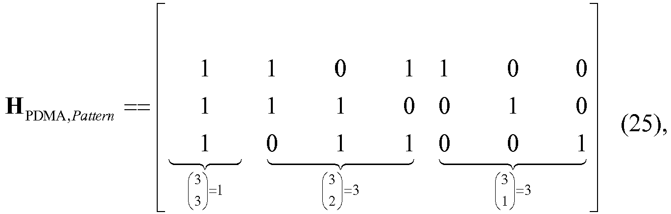
- The PDMA encoding matrix H PDMA,Pattern may be defined through the following equation:

- In
Step 201, the channel estimation may be performed on the signal received by each antenna in the NR (NR = 2) antennae, so as to acquire the channel estimation matrix for all the transmitters that have multiplexed the identical time-frequency resources on each antenna. - To be specific, the transmitters that have multiplexed the identical two REs may be separated from each other based on a received pilot signal


- In
Step 202, the equivalent channel estimation matrix


- The equivalent multi-antenna received signal matrix


- The equivalent multi-antenna PDMA channel estimation matrix


- Hence, the communication model may be represented as:


- In
Step 203, a value of the decision parameter η may be calculated. η = 4/12 = 1/3, i.e., the value of the decision parameter η is smaller than the decision threshold ηth (ηth = 0.5), and the number of rows of the matrix


- The QR decomposition may be performed on the matrix


- The BP joint detection may be performed based on the equivalent multi-antenna received signal


- In
Step 204, the LLRs for the transmitters acquired inStep 203 after the detection may be decoded by a Turbo decoding module, so as to acquire the original multi-user information from the transmission end. -
Fig.3 shows a BP detection procedure inStep 203. - In some other embodiments of the present disclosure, a 1Tx2Rx and 3RE7UE transmission mode may be adopted in an uplink direction including. 1Tx2Rx represents the existence of one transmission antenna and two reception antennae (i.e., the number of antennae at the receiving end NR = 2), and 3RE7UE represents that the data for seven transmitters is transmitted on three REs. The decision threshold ηth = 0.5, and a BP algorithm is adopted for the joint detection.
- The PDMA encoding matrix H PDMA,Pattern is a 3×7 matrix, i.e., M=3 and N=7. The PDMA encoding matrix H PDMA,Pattern may be defined through the following equation:
- In
Step 201, the channel estimation may be performed on the signal received by ach antenna in the NR (NR = 2) antennae, so as to acquire the channel estimation matrix for all the transmitters that have multiplexed the identical time-frequency resources on each antenna. - To be specific, the transmitters that have multiplexed the identical three REs may be separated from each other based on the received pilot signal


- In
Step 202, the equivalent channel estimation matrix


- The equivalent multi-antenna received signal matrix


- The equivalent multi-antenna PDMA channel estimation matrix


- Hence, the communication model may be represented as:

- In
Step 203, a value of the decision parameter η may be calculated. η = 18 / 42 = 3 / 7, i.e., the value of the decision parameter η is smaller than the decision threshold ηth (ηth = 0.5), and the number of rows of the matrix


Step 202 as well as the set Ω of the constellation points of the transmitters, so as to acquire the LLRs for all the transmitters after the detection through the following equation:
- In
Step 204, the LLRs for the transmitters acquired inStep 203 after the detection may be decoded by the Turbo decoding module, so as to acquire the original multi-user information from the transmission end. -
Fig.4 shows a BP detection procedure inStep 203. - In order to compare the signal detection algorithm in the embodiments of the present disclosure with a signal detection algorithm in the related art, a procedure of adopting the traditional signal detection algorithm will be described hereinafter by taking the above-mentioned situation as an example.
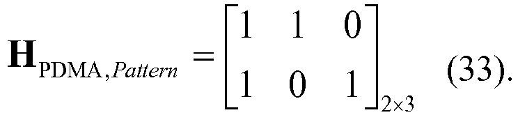
- In a scenario where the data from three transmitters is transmitted on two REs, the data is transmitted at the transmitting end through a single antenna and the data is received at the receiving end through two antennae, the PDMA encoding matrix H PDMA,Pattern may be defined as follows:


- During the BP detection using the PDMA system in the related art, the signal to be transmitted by each antenna may be detected using the signal received by the antennae through the BP algorithm on the basis of the model shown by above-mentioned equations (34) and (35), and the LLRs for all the reception antennae may be combined after the detection, and then the turbo decoding operation may be performed. In other words,
antenna 1 may use the receivedsignals 

antenna 2 may use the receivedsignals 

Fig.5 shows the BP detection in the related art. - Taking UE1 as an example, the LLR may be calculated through the following equation:

- It can be seen by comparing
Fig.3 withFig.5 that, although the BP detection method in the embodiments of the present disclosure and the BP detection method in the related art have an identical number of variable nodes, i.e., 3 (e.g., nodes u in the figures), for the former, there are 4 observer nodes (e.g., nodes c in theFig.5 ), while for the latter, there are 2 observer nodes. In other words, the BP detection method in the embodiments of the present disclosure may have all the observer nodes doubling those of the detection method in the related art. In this way, it is able to use all the received signals as an input parameter for the detection method, and facilitate the complete information action between the observer nodes and the variable nodes, thereby to improve the detection accuracy. - On the basis of a mutual information theory, in the case that the channels from the transmitters to the antennae at the receiving end are separate from each other, the BP detection method in the embodiments of the present disclosure may have performance equivalent to the BP detection method in the related art. However, in the case that there is correlation between the channels from the transmitters to the antennae at the receiving end, the BP detection method in the embodiments of the present disclosure may have performance better than the BP detection method in the related art.
- The above description is given by taking the BP detection method as an example. Of course, the same technical effect may be achieved by replacing the BP detection method as an IDD detection method.
- Based on an identical inventive concept, the present disclosure further provides in some embodiments a signal detection device
- As shown in
Fig.6 , the signal detection device may include achannel estimation module 601, an equivalentchannel determination module 602, ajoint detection module 603 anddecoding module 604. Thechannel estimation module 601 is configured to perform channel estimation based on a signal received by each of antennae to acquire a channel estimation matrix for all transmitters multiplexing on identical time-frequency resources on each of the antennae. The equivalentchannel determination module 602 is configured to determine an equivalent PDMA channel estimation matrix for each of the antennae based on a PDMA encoding matrix and the channel estimation matrix for all the transmitters multiplexing on the identical time-frequency resources on each of the antennae, and acquire an equivalent multi-antenna PDMA channel estimation matrix for the antennae based on the equivalent PDMA channel estimation matrix for each of the antennae. Thejoint detection module 603 is configured to perform a joint detection based on the equivalent multi-antenna PDMA channel estimation matrix, an equivalent multi-antenna received signal vector and a set of constellation points of the transmitters multiplexing on the identical time-frequency resources to acquire LLRs for all the transmitters, where the equivalent multi-antenna received signal vector is formed based on the signals received by the antennae. Thedecoding module 604 is configured to decode the LLRs for all the transmitters to acquire multi-user information at transmitting end. - Optionally, the equivalent
channel determination module 602 may be further configured to perform calculation based on the channel estimation matrix for all the transmitters for transmission that have multiplexed on the identical time-frequency resources for each antenna and the PDMA encoding matrix through the above-mentioned equation (5), so as to acquire the equivalent PDMA channel estimation matrix for each antenna. The equation (5) and the parameters thereof may refer to those mentioned above, and thus will not be particularly defined herein. - Optionally, the
joint detection module 603 may be further configured to: determine whether the equivalent multi-antenna PDMA channel estimation matrix and the equivalent multi-antenna received signal vector are to be linearly transformed, based on a characteristic of the equivalent multi-antenna PDMA channel estimation matrix; and in the case that the equivalent multi-antenna PDMA channel estimation matrix and the equivalent multi-antenna received signal vector are to be linearly transformed, linearly transform the equivalent multi-antenna PDMA channel estimation matrix and the equivalent multi-antenna received signal vector, and perform the joint detection based on the equivalent multi-antenna PDMA channel estimation matrix and the equivalent multi-antenna received signal vector which are linearly transformed and the set of constellation points of the transmitters multiplexing on the identical time-frequency resources to acquire the LLRs for the transmitters. - The
joint detection module 603 may be further configured to: in the case that a ratio of the number of elements each having a value of 0 in the equivalent multi-antenna PDMA channel estimation matrix to the number of all the elements is smaller than or equal to a decision threshold and the number of rows of the equivalent multi-antenna PDMA channel estimation matrix is greater than or equal to the number of columns of the equivalent multi-antenna PDMA channel estimation matrix, determine to linearly transform the equivalent multi-antenna PDMA channel estimation matrix and the equivalent multi-antenna received signal vector. - Optionally, the
joint detection module 603 may be further configured to perform QR decomposition on the equivalent multi-antenna PDMA channel estimation matrix. - Optionally, the
joint detection module 603 may be further configured to perform the joint detection using a BP detection algorithm or an IDD detection algorithm. - Based on an identical inventive concept, the present disclosure further provides in some embodiments a communication device which may be a base station, a UE, or any other device having a capability of receiving and processing a wireless signal.
- As shown in
Fig.7 , the communication device may include aprocessor 701, amemory 702, atransceiver 703 and a bus interface. - The
processor 701 may take charge of managing the bus architecture as well as general processing. Thememory 702 may store therein data for the operation of theprocessor 701. Thetransceiver 703 may be configured to receive and transmit data under the control of theprocessor 701. - In
Fig.7 , bus architecture represented by a bus may include a number of buses and bridges connected to each other, so as to connect various circuits for one ormore processors 701 and one ormore memories 702. In addition, as is known in the art, the bus architecture may be used to connect any other circuits, such as a circuit for a peripheral device, a circuit for a voltage stabilizer and a power management circuit. Bus interfaces are provided, and thetransceiver 703 may consist of one or more elements, i.e., a plurality of transmitters and a plurality of receivers for communication with any other devices over a transmission medium. Theprocessor 701 may take charge of managing the bus architecture as well as general processing. Thememory 702 may store therein data for the operation of theprocessor 701. - The
processor 701 may be further configured to read a program stored in thememory 702, so as to: perform channel estimation based on a signal received by each of antennae, to acquire a channel estimation matrix for all transmitters multiplexing on identical time-frequency resources on each of the antennae, determine an equivalent PDMA channel estimation matrix for each of the antennae based on a PDMA encoding matrix and the channel estimation matrix for all the transmitters multiplexing on the identical time-frequency resources on each of the antennae, and acquire an equivalent multi-antenna PDMA channel estimation matrix for all the antennae based on the equivalent PDMA channel estimation matrix for each of the antennae, perform a joint detection based on the equivalent multi-antenna PDMA channel estimation matrix, an equivalent multi-antenna received signal vector and a set of constellation points of the transmitters multiplexing on the identical time-frequency resources, to acquire LLRs for all the transmitters, where the equivalent multi-antenna received signal vector is formed based on the signals received by the antennae, and decode the LLRs for all the transmitters, to acquire multi-user information at transmitting end. - Optionally, the
processor 701 may be further configured to perform calculation based on the channel estimation matrix for all the transmitters for transmission that have multiplexed on the identical time-frequency resources for each antenna and the PDMA encoding matrix through the above-mentioned equation (5), so as to acquire the equivalent PDMA channel estimation matrix for each antenna. The equation (5) and the parameters thereof may refer to those mentioned above, and thus will not be particularly defined herein. - Optionally, the
processor 701 may be further configured to: determine whether the equivalent multi-antenna PDMA channel estimation matrix and the equivalent multi-antenna received signal vector are to be linearly transformed, based on a characteristic of the equivalent multi-antenna PDMA channel estimation matrix; and in the case that the equivalent multi-antenna PDMA channel estimation matrix and the equivalent multi-antenna received signal vector are to be linearly transformed, linearly transform the equivalent multi-antenna PDMA channel estimation matrix and the equivalent multi-antenna received signal vector, and perform the joint detection based on the equivalent multi-antenna PDMA channel estimation matrix and the equivalent multi-antenna received signal vector which are linearly transformed and the set of constellation points of the transmitters multiplexing on the identical time-frequency resources to acquire the LLRs for all the transmitters. - The
processor 701 may be further configured to: in the case that a ratio of the number of elements each having a value of 0 in the equivalent multi-antenna PDMA channel estimation matrix to the number of all the elements is smaller than or equal to a decision threshold and the number of rows of the equivalent multi-antenna PDMA channel estimation matrix is greater than or equal to the number of columns of the equivalent multi-antenna PDMA channel estimation matrix, determine to linearly transform the equivalent multi-antenna PDMA channel estimation matrix and the equivalent multi-antenna received signal vector. - Optionally, the
processor 701 may be further configured to perform QR decomposition on the equivalent multi-antenna PDMA channel estimation matrix. - Optionally, the
processor 701 may be further configured to perform the joint detection using a BP detection algorithm or an IDD detection algorithm. - In a word, according to the embodiments of the present disclosure, as compared with the conventional multi-antenna BP detection method, it is able for the BP detection method in the embodiments of the present disclosure to increase the information redundancy by full use of the mutual information about the received signal and the channel among the antennae, so as to improve the detection performance and increase the total system throughput. In the case that the antennae are completely separate from each other, the signal detection method in the embodiments of the present disclosure may have the performance equivalent to the conventional multi-antenna BP detection method, and in the case that there is the correlation between the antennae, the signal detection method in the embodiments of the present disclosure may have the performance better than the conventional multi-antenna BP detection method.
- In the case of a 1Tx2Rx and 2RE3UE transmission mode, the number of the observer nodes for the signal detection method in the embodiments of the present disclosure may be 4, while the number of the observer nodes for the conventional BP detection method may be 2. In other words, the number of the observer nodes for the signal detection method in the embodiments of the present disclosure is twice that for the conventional BP detection method. As a result, it is able to use all the received signals as the input parameter for the detection algorithm and facilitate the complete information interaction between the observer nodes and the variable nodes, thereby to improve the detection accuracy.
- The present disclosure has been described with reference to the flow charts and/or block diagrams of the method, device (system) and computer program product according to the embodiments of the present disclosure. It should be understood that computer program instructions may be used to implement each of the work flows and/or blocks in the flow charts and/or the block diagrams, and the combination of the work flows and/or blocks in the flow charts and/or the block diagrams. These computer program instructions may be provided to a processor of a common computer, a dedicate computer, an embedded processor or any other programmable data processing devices to create a machine, so that instructions executable by the processor of the computer or the other programmable data processing devices may create a device to achieve the functions assigned in one or more work flows in the flow chart and/or one or more blocks in the block diagram.
- These computer program instructions may also be stored in a computer readable storage that may guide the computer or the other programmable data process devices to function in a certain way, so that the instructions stored in the computer readable storage may create a product including an instruction unit which achieves the functions assigned in one or more flows in the flow chart and/or one or more blocks in the block diagram.
- These computer program instructions may also be loaded in the computer or the other programmable data process devices, so that a series of operation steps are executed on the computer or the other programmable devices to create processes achieved by the computer. Therefore, the instructions executed in the computer or the other programmable devices provide the steps for achieving the function assigned in one or more flows in the flow chart and/or one or more blocks in the block diagram.
- Although the preferred embodiments are described above, a person skilled in the art may make modifications and alterations to these embodiments based on the basic concept of the present disclosure. So, the attached claims are intended to include the preferred embodiments and all of the modifications and alterations that fall within the scope of the present disclosure.
- The above are merely the preferred embodiments of the present disclosure, but the present disclosure is not limited thereto.
Claims (11)
- A signal detection method, comprising:performing channel estimation based on a signal received by each of antennae, to acquire a channel estimation matrix for transmitters multiplexing on identical time-frequency resources on each of the antennae (201);determining an equivalent Pattern Division Multiple Access, PDMA, channel estimation matrix for each of the antennae based on a PDMA encoding matrix and the channel estimation matrix for the transmitters multiplexing the identical time-frequency resources on each of the antennae, and acquiring an equivalent multi-antenna PDMA channel estimation matrix for the antennae based on the equivalent PDMA channel estimation matrix for each of the antennae (202);performing a joint detection based on the equivalent multi-antenna PDMA channel estimation matrix, an equivalent multi-antenna received signal vector and a set of constellation points of the transmitters multiplexing on the identical time-frequency resources, to acquire Log Likelihood Ratios, LLRs, for the transmitters, wherein the equivalent multi-antenna received signal vector is formed based on the signals received by the antennae (203); anddecoding the LLRs for the transmitters, to acquire multi-user information at transmitting end (204),characterized in that the determining the equivalent PDMA channel estimation matrix for each of the antennae based on the PDMA encoding matrix and the channel estimation matrix for the transmitters multiplexing on the identical time-frequency resources on each of the antennae comprises:
performing a calculation based on the channel estimation matrix for the transmitters multiplexing on the identical time-frequency resources on each of the antennae and the PDMA encoding matrix to acquire the equivalent PDMA channel estimation matrix for each of the antennae through an equation: wherein

 wherein the PDMA encoding matrix H PDMA,Pattern is defined as:
- The signal detection method according to claim 1, wherein the performing the joint detection based on the equivalent multi-antenna PDMA channel estimation matrix, the equivalent multi-antenna received signal vector and the set of constellation points of the transmitters multiplexing on the identical time-frequency resources to acquire the LLRs for the transmitters comprises:determining whether the equivalent multi-antenna PDMA channel estimation matrix and the equivalent multi-antenna received signal vector are to be linearly transformed, based on a characteristic of the equivalent multi-antenna PDMA channel estimation matrix; andin the case that the equivalent multi-antenna PDMA channel estimation matrix and the equivalent multi-antenna received signal vector are to be linearly transformed, linearly transforming the equivalent multi-antenna PDMA channel estimation matrix, the equivalent multi-antenna received signal vector, and performing the joint detection based on the equivalent multi-antenna PDMA channel estimation matrix and the equivalent multi-antenna received signal vector which are linearly transformed, and the set of constellation points of the transmitters multiplexing on the identical time-frequency resources, to acquire the LLRs for the transmitters.
- The signal detection method according to claim 2, wherein the determining whether the equivalent multi-antenna PDMA channel estimation matrix and the equivalent multi-antenna received signal vector are to be linearly transformed, based on a characteristic of the equivalent multi-antenna PDMA channel estimation matrix comprises:
in the case that a ratio of the number of elements each having a value of 0 in the equivalent multi-antenna PDMA channel estimation matrix to the number of all the elements is smaller than or equal to a decision threshold, and the number of rows of the equivalent multi-antenna PDMA channel estimation matrix is greater than or equal to the number of columns of the equivalent multi-antenna PDMA channel estimation matrix, determining to linearly transform the equivalent multi-antenna PDMA channel estimation matrix and the equivalent multi-antenna received signal vector. - The signal detection method according to claim 2, wherein the linearly transforming the equivalent multi-antenna PDMA channel estimation matrix comprises:
performing quadrature rectangle, QR, decomposition on the equivalent multi-antenna PDMA channel estimation matrix. - The signal detection method according to any one of claims 1 to 4, wherein the joint detection comprises performing the joint detection through a Belief Propagation, BP, detection algorithm or an Iterative Detection and Decoding, IDD, detection algorithm.
- A signal detection device, comprising:a channel estimation module (601), configured to perform channel estimation based on a signal received by each of antennae to acquire a channel estimation matrix for transmitters multiplexing on identical time-frequency resources on each of the antennae;an equivalent channel determination module (602), configured to determine an equivalent Pattern Division Multiple Access, PDMA, channel estimation matrix for each of the antennae based on a PDMA encoding matrix and the channel estimation matrix for the transmitters multiplexing on the identical time-frequency resources on each of the antennae, and acquire an equivalent multi-antenna PDMA channel estimation matrix for the antennae based on the equivalent PDMA channel estimation matrix for each of the antennae;a joint detection module (603), configured to perform a joint detection based on the equivalent multi-antenna PDMA channel estimation matrix, an equivalent multi-antenna received signal vector and a set of constellation points of the transmitters multiplexing on the identical time-frequency resources to acquire Log Likelihood Ratios, LLRs, for the transmitters, wherein the equivalent multi-antenna received signal vector is formed based on the signals received by the antennae; anda decoding module (604), configured to decode the LLRs for the transmitters to acquire multi-user information at the transmitting end,characterized in that the equivalent channel determination module (602) is further configured to perform a calculation based on the channel estimation matrix for the transmitters multiplexing on the identical time-frequency resources on each of the antennae and the PDMA encoding matrix to acquire the equivalent PDMA channel estimation matrix for each of the antennae through an equation:
 wherein
 wherein the PDMA encoding matrix H PDMA,Pattern is defined as:
- The signal detection device according to claim 6, wherein the joint detection module (603) is further configured to:determine whether the equivalent multi-antenna PDMA channel estimation matrix and the equivalent multi-antenna received signal vector are to be linearly transformed, based on a characteristic of the equivalent multi-antenna PDMA channel estimation matrix; andin the case that the equivalent multi-antenna PDMA channel estimation matrix and the equivalent multi-antenna received signal vector are to be linearly transformed, linearly transform the equivalent multi-antenna PDMA channel estimation matrix, the equivalent multi-antenna received signal vector, and perform the joint detection based on the equivalent multi-antenna PDMA channel estimation matrix, and the equivalent multi-antenna received signal vector which are linearly transformed and the set of constellation points of the transmitters multiplexing on the identical time-frequency resources to acquire the LLRs for the transmitters.
- The signal detection device according to claim 7, wherein the joint detection module (603) is further configured to, in the case that a ratio of the number of elements each having a value of 0 in the equivalent multi-antenna PDMA channel estimation matrix to the number of all the elements is smaller than or equal to a decision threshold, and the number of rows of the equivalent multi-antenna PDMA channel estimation matrix is greater than or equal to the number of columns of the equivalent multi-antenna PDMA channel estimation matrix, determine to linearly transform the equivalent multi-antenna PDMA channel estimation matrix and the equivalent multi-antenna received signal vector.
- The signal detection device according to claim 7, wherein the joint detection module (603) is further configured to perform quadrature rectangle, QR, decomposition on the equivalent multi-antenna PDMA channel estimation matrix.
- The signal detection device according to any one of claims 6 to 9, wherein the joint detection module (603) is further configured to perform the joint detection through a Belief Propagation, BP, detection algorithm or an Iterative Detection and Decoding, IDD, detection algorithm.
- A signal detection device, comprising a processor (701), a transceiver (703) and a memory (702), wherein
the processor (701) is configured to read a program stored in the memory (702) to:perform channel estimation based on a signal received by each of antennae, to acquire a channel estimation matrix for transmitters multiplexing on identical time-frequency resources on each of the antennae,determine an equivalent Pattern Division Multiple Access, PDMA, channel estimation matrix for each of the antennae based on a PDMA encoding matrix and the channel estimation matrix for the transmitters multiplexing on the identical time-frequency resources on each of the antennae, and acquire an equivalent multi-antenna PDMA channel estimation matrix for the antennae based on the equivalent PDMA channel estimation matrix for each of the antennae,perform a joint detection based on the equivalent multi-antenna PDMA channel estimation matrix, an equivalent multi-antenna received signal vector and a set of constellation points of the transmitters multiplexing on the identical time-frequency resources, to acquire Log Likelihood Ratios, LLRs, for the transmitters, wherein the equivalent multi-antenna received signal vector is formed based on the signals received by the antennae, anddecode the LLRs for the transmitters, to acquire multi-user information at the transmitting end;the transceiver (703) is configured to receive and transmit data; andthe memory (702) is configured to store data for the operation of the processor,characterized in that the processor (701) is configured to read a program stored in the memory (702) to:
perform a calculation based on the channel estimation matrix for the transmitters multiplexing on the identical time-frequency resources on each of the antennae and the PDMA encoding matrix to acquire the equivalent PDMA channel estimation matrix for each of the antennae through an equation: wherein
 wherein the PDMA encoding matrix H PDMA,Pattern is defined as:
Applications Claiming Priority (2)
| Application Number | Priority Date | Filing Date | Title |
|---|---|---|---|
| CN201510129081.XA CN106160831B (en) | 2015-03-23 | 2015-03-23 | A kind of signal detecting method and device |
| PCT/CN2016/072269 WO2016150246A1 (en) | 2015-03-23 | 2016-01-27 | Signal detection method and device |
Publications (3)
| Publication Number | Publication Date |
|---|---|
| EP3276852A1 EP3276852A1 (en) | 2018-01-31 |
| EP3276852A4 EP3276852A4 (en) | 2018-04-18 |
| EP3276852B1 true EP3276852B1 (en) | 2019-12-18 |
Family
ID=56977861
Family Applications (1)
| Application Number | Title | Priority Date | Filing Date |
|---|---|---|---|
| EP16767623.8A Active EP3276852B1 (en) | 2015-03-23 | 2016-01-27 | Signal detection method and signal detection device |
Country Status (5)
| Country | Link |
|---|---|
| US (1) | US10355883B2 (en) |
| EP (1) | EP3276852B1 (en) |
| CN (1) | CN106160831B (en) |
| TW (1) | TWI591973B (en) |
| WO (1) | WO2016150246A1 (en) |
Families Citing this family (8)
| Publication number | Priority date | Publication date | Assignee | Title |
|---|---|---|---|---|
| EP3258605A4 (en) * | 2015-02-10 | 2018-03-28 | Panasonic Intellectual Property Management Co., Ltd. | Transmitting method, transmitting device, receiving method and receiving device |
| CN111628853B (en) * | 2017-01-05 | 2021-12-10 | 华为技术有限公司 | Method and device for transmitting data |
| CN107332614B (en) * | 2017-06-20 | 2019-12-27 | 中国矿业大学 | Optimization method for robust beam forming of visible light communication non-orthogonal multiple access technology |
| CN110831119B (en) * | 2018-08-09 | 2022-03-22 | 大唐移动通信设备有限公司 | Multi-layer transmission data processing method and entity |
| US10778300B2 (en) * | 2018-12-03 | 2020-09-15 | Samsung Electronics Co., Ltd | Method and apparatus for high rank multiple-input multiple-output (MIMO) symbol detection |
| CN112217549B (en) * | 2020-10-14 | 2021-08-20 | 西安电子科技大学 | Integrated multi-user detection method and system based on signal virtual processing |
| US11729028B2 (en) * | 2020-12-17 | 2023-08-15 | Skyworks Solutions, Inc. | System and method for blind channel estimation and coherent differential equalization in an orthogonal frequency division multiplexing (OFDM) receiver |
| CN114301742B (en) * | 2021-12-23 | 2024-01-09 | 北京邮电大学 | Channel estimation method and device |
Family Cites Families (15)
| Publication number | Priority date | Publication date | Assignee | Title |
|---|---|---|---|---|
| US7317770B2 (en) * | 2003-02-28 | 2008-01-08 | Nec Laboratories America, Inc. | Near-optimal multiple-input multiple-output (MIMO) channel detection via sequential Monte Carlo |
| CN100542080C (en) * | 2003-09-29 | 2009-09-16 | 富士通株式会社 | Associated detecting method and device and use the system of this device |
| EP1746756B1 (en) * | 2005-07-21 | 2013-01-16 | STMicroelectronics Srl | A method and system for decoding signals, corresponding receiver and computer program product |
| WO2007035067A2 (en) * | 2005-09-23 | 2007-03-29 | Electronics And Telecommunications Research Institute | Mimo system performing hybrid arq and retransmission method thereof |
| CN101388872B (en) | 2007-09-10 | 2012-08-29 | 华为技术有限公司 | Data signal modulation, demodulation method, transceiver and transceiving system |
| US8989320B2 (en) * | 2009-09-02 | 2015-03-24 | Qualcomm Incorporated | Hardware simplification of sic-MIMO decoding by use of a single hardware element with channel and noise adaptation for interference cancelled streams |
| US8514984B2 (en) * | 2009-09-02 | 2013-08-20 | Qualcomm Incorporated | Iterative decoding architecture with HARQ combining and soft decision directed channel estimation |
| CN102668611A (en) * | 2009-11-27 | 2012-09-12 | 高通股份有限公司 | Interference cancellation for non-orthogonal channel sets |
| CN102325001B (en) | 2011-05-24 | 2013-07-31 | 东南大学 | Bandwidth-adaptive big iteration receiver |
| CN102832986B (en) * | 2011-06-13 | 2016-04-20 | 联芯科技有限公司 | A kind of multi-antenna diversity merges method of reseptance and equipment |
| US9191256B2 (en) * | 2012-12-03 | 2015-11-17 | Digital PowerRadio, LLC | Systems and methods for advanced iterative decoding and channel estimation of concatenated coding systems |
| US9166663B2 (en) * | 2012-12-14 | 2015-10-20 | Futurewei Technologies, Inc. | System and method for open-loop MIMO communications in a SCMA communications system |
| CN104079511B (en) * | 2014-06-17 | 2017-09-12 | 华为技术有限公司 | The method and device of maximum likelihood ML Data processing of receiver |
| CN107786482B (en) * | 2016-08-19 | 2021-06-04 | 北京三星通信技术研究有限公司 | Multi-terminal information receiving and sending method based on grid mapping and corresponding equipment |
| US10700912B2 (en) * | 2017-05-19 | 2020-06-30 | Huawei Technologies Co., Ltd. | Method and system for non-orthogonal multiple access communication |
-
2015
- 2015-03-23 CN CN201510129081.XA patent/CN106160831B/en active Active
-
2016
- 2016-01-27 US US15/561,357 patent/US10355883B2/en active Active
- 2016-01-27 WO PCT/CN2016/072269 patent/WO2016150246A1/en active Application Filing
- 2016-01-27 EP EP16767623.8A patent/EP3276852B1/en active Active
- 2016-02-01 TW TW105103090A patent/TWI591973B/en active
Non-Patent Citations (1)
| Title |
|---|
| None * |
Also Published As
| Publication number | Publication date |
|---|---|
| CN106160831B (en) | 2019-09-17 |
| CN106160831A (en) | 2016-11-23 |
| EP3276852A4 (en) | 2018-04-18 |
| US20180083802A1 (en) | 2018-03-22 |
| US10355883B2 (en) | 2019-07-16 |
| TWI591973B (en) | 2017-07-11 |
| TW201635736A (en) | 2016-10-01 |
| WO2016150246A1 (en) | 2016-09-29 |
| EP3276852A1 (en) | 2018-01-31 |
Similar Documents
| Publication | Publication Date | Title |
|---|---|---|
| EP3276852B1 (en) | Signal detection method and signal detection device | |
| US20220329289A1 (en) | Methods, distributed base station system, remote radio unit and base band unit system for handling uplink signals | |
| US9160383B2 (en) | Method for estimating covariance matrices and use thereof | |
| US9722679B2 (en) | Method and apparatus for estimating communication channel in mobile communication system | |
| CN102546088B (en) | A kind of block diagonalization method for precoding and device | |
| EP2871789B1 (en) | Method for estimating covariance matrices and use thereof | |
| EP3291498A1 (en) | Apparatus and method for estimating downlink channel in wireless communication system | |
| US20230403182A1 (en) | Radio Receiver | |
| CN104243377B (en) | A kind of disturbance restraining method and device | |
| CN104488214B (en) | For combining the method and apparatus for performing channel estimation and Interference Estimation in a wireless communication system | |
| EP2667555A1 (en) | Method and apparatus for the demodulation of a received signal | |
| CN110557348B (en) | Method and communication device for demodulating data | |
| CN107078836A (en) | The generation method and device of a kind of pilot signal | |
| US20100158080A1 (en) | Wireless reception device, wireless communication system and wireless communication method | |
| EP2988446B1 (en) | Multiple-input multiple-output (mimo) detection method, apparatus and system for transmitting signal | |
| EP2869485B1 (en) | Equalizing Method in a Receiver Node of a Wireless Communication System | |
| CN103179056B (en) | Channel estimation methods and device | |
| EP3001626B1 (en) | Eqalizer for joint-equalization | |
| CN105027477A (en) | Signal detection method and device | |
| CN108418619A (en) | A kind of signal detecting method and device | |
| CN102739282B (en) | Multi-antenna combined detection system of TD-SCDMA system and multi-antenna combined detection method thereof | |
| CN102832986A (en) | Multi-antenna diversity combination receiving method and device | |
| EP2651085A1 (en) | Method and apparatus for iterative detection of data streams | |
| CN107483374B (en) | A kind of method and apparatus for realizing uplink receiving detection | |
| US10419183B2 (en) | Method and apparatus for sending and receiving signal |
Legal Events
| Date | Code | Title | Description |
|---|---|---|---|
| STAA | Information on the status of an ep patent application or granted ep patent |
Free format text: STATUS: THE INTERNATIONAL PUBLICATION HAS BEEN MADE |
|
| PUAI | Public reference made under article 153(3) epc to a published international application that has entered the european phase |
Free format text: ORIGINAL CODE: 0009012 |
|
| STAA | Information on the status of an ep patent application or granted ep patent |
Free format text: STATUS: REQUEST FOR EXAMINATION WAS MADE |
|
| 17P | Request for examination filed |
Effective date: 20170928 |
|
| AK | Designated contracting states |
Kind code of ref document: A1 Designated state(s): AL AT BE BG CH CY CZ DE DK EE ES FI FR GB GR HR HU IE IS IT LI LT LU LV MC MK MT NL NO PL PT RO RS SE SI SK SM TR |
|
| AX | Request for extension of the european patent |
Extension state: BA ME |
|
| A4 | Supplementary search report drawn up and despatched |
Effective date: 20180316 |
|
| RIC1 | Information provided on ipc code assigned before grant |
Ipc: H04B 7/08 20060101ALI20180312BHEP Ipc: H04B 7/06 20060101AFI20180312BHEP Ipc: H04B 7/0452 20170101ALN20180312BHEP |
|
| DAV | Request for validation of the european patent (deleted) | ||
| DAX | Request for extension of the european patent (deleted) | ||
| STAA | Information on the status of an ep patent application or granted ep patent |
Free format text: STATUS: EXAMINATION IS IN PROGRESS |
|
| 17Q | First examination report despatched |
Effective date: 20190205 |
|
| REG | Reference to a national code |
Ref country code: DE Ref legal event code: R079 Ref document number: 602016026498 Country of ref document: DE Free format text: PREVIOUS MAIN CLASS: H04B0007080000 Ipc: H04B0007060000 |
|
| GRAP | Despatch of communication of intention to grant a patent |
Free format text: ORIGINAL CODE: EPIDOSNIGR1 |
|
| STAA | Information on the status of an ep patent application or granted ep patent |
Free format text: STATUS: GRANT OF PATENT IS INTENDED |
|
| RIC1 | Information provided on ipc code assigned before grant |
Ipc: H04B 7/08 20060101ALI20190703BHEP Ipc: H04B 7/0452 20170101ALN20190703BHEP Ipc: H04B 7/06 20060101AFI20190703BHEP |
|
| INTG | Intention to grant announced |
Effective date: 20190716 |
|
| GRAS | Grant fee paid |
Free format text: ORIGINAL CODE: EPIDOSNIGR3 |
|
| GRAA | (expected) grant |
Free format text: ORIGINAL CODE: 0009210 |
|
| STAA | Information on the status of an ep patent application or granted ep patent |
Free format text: STATUS: THE PATENT HAS BEEN GRANTED |
|
| AK | Designated contracting states |
Kind code of ref document: B1 Designated state(s): AL AT BE BG CH CY CZ DE DK EE ES FI FR GB GR HR HU IE IS IT LI LT LU LV MC MK MT NL NO PL PT RO RS SE SI SK SM TR |
|
| REG | Reference to a national code |
Ref country code: CH Ref legal event code: EP |
|
| REG | Reference to a national code |
Ref country code: IE Ref legal event code: FG4D |
|
| REG | Reference to a national code |
Ref country code: DE Ref legal event code: R096 Ref document number: 602016026498 Country of ref document: DE |
|
| REG | Reference to a national code |
Ref country code: AT Ref legal event code: REF Ref document number: 1215710 Country of ref document: AT Kind code of ref document: T Effective date: 20200115 |
|
| REG | Reference to a national code |
Ref country code: NL Ref legal event code: MP Effective date: 20191218 |
|
| PG25 | Lapsed in a contracting state [announced via postgrant information from national office to epo] |
Ref country code: SE Free format text: LAPSE BECAUSE OF FAILURE TO SUBMIT A TRANSLATION OF THE DESCRIPTION OR TO PAY THE FEE WITHIN THE PRESCRIBED TIME-LIMIT Effective date: 20191218 Ref country code: LV Free format text: LAPSE BECAUSE OF FAILURE TO SUBMIT A TRANSLATION OF THE DESCRIPTION OR TO PAY THE FEE WITHIN THE PRESCRIBED TIME-LIMIT Effective date: 20191218 Ref country code: GR Free format text: LAPSE BECAUSE OF FAILURE TO SUBMIT A TRANSLATION OF THE DESCRIPTION OR TO PAY THE FEE WITHIN THE PRESCRIBED TIME-LIMIT Effective date: 20200319 Ref country code: NO Free format text: LAPSE BECAUSE OF FAILURE TO SUBMIT A TRANSLATION OF THE DESCRIPTION OR TO PAY THE FEE WITHIN THE PRESCRIBED TIME-LIMIT Effective date: 20200318 Ref country code: FI Free format text: LAPSE BECAUSE OF FAILURE TO SUBMIT A TRANSLATION OF THE DESCRIPTION OR TO PAY THE FEE WITHIN THE PRESCRIBED TIME-LIMIT Effective date: 20191218 Ref country code: BG Free format text: LAPSE BECAUSE OF FAILURE TO SUBMIT A TRANSLATION OF THE DESCRIPTION OR TO PAY THE FEE WITHIN THE PRESCRIBED TIME-LIMIT Effective date: 20200318 Ref country code: LT Free format text: LAPSE BECAUSE OF FAILURE TO SUBMIT A TRANSLATION OF THE DESCRIPTION OR TO PAY THE FEE WITHIN THE PRESCRIBED TIME-LIMIT Effective date: 20191218 |
|
| REG | Reference to a national code |
Ref country code: LT Ref legal event code: MG4D |
|
| PG25 | Lapsed in a contracting state [announced via postgrant information from national office to epo] |
Ref country code: HR Free format text: LAPSE BECAUSE OF FAILURE TO SUBMIT A TRANSLATION OF THE DESCRIPTION OR TO PAY THE FEE WITHIN THE PRESCRIBED TIME-LIMIT Effective date: 20191218 Ref country code: RS Free format text: LAPSE BECAUSE OF FAILURE TO SUBMIT A TRANSLATION OF THE DESCRIPTION OR TO PAY THE FEE WITHIN THE PRESCRIBED TIME-LIMIT Effective date: 20191218 |
|
| PG25 | Lapsed in a contracting state [announced via postgrant information from national office to epo] |
Ref country code: AL Free format text: LAPSE BECAUSE OF FAILURE TO SUBMIT A TRANSLATION OF THE DESCRIPTION OR TO PAY THE FEE WITHIN THE PRESCRIBED TIME-LIMIT Effective date: 20191218 |
|
| PG25 | Lapsed in a contracting state [announced via postgrant information from national office to epo] |
Ref country code: RO Free format text: LAPSE BECAUSE OF FAILURE TO SUBMIT A TRANSLATION OF THE DESCRIPTION OR TO PAY THE FEE WITHIN THE PRESCRIBED TIME-LIMIT Effective date: 20191218 Ref country code: EE Free format text: LAPSE BECAUSE OF FAILURE TO SUBMIT A TRANSLATION OF THE DESCRIPTION OR TO PAY THE FEE WITHIN THE PRESCRIBED TIME-LIMIT Effective date: 20191218 Ref country code: PT Free format text: LAPSE BECAUSE OF FAILURE TO SUBMIT A TRANSLATION OF THE DESCRIPTION OR TO PAY THE FEE WITHIN THE PRESCRIBED TIME-LIMIT Effective date: 20200513 Ref country code: NL Free format text: LAPSE BECAUSE OF FAILURE TO SUBMIT A TRANSLATION OF THE DESCRIPTION OR TO PAY THE FEE WITHIN THE PRESCRIBED TIME-LIMIT Effective date: 20191218 Ref country code: CZ Free format text: LAPSE BECAUSE OF FAILURE TO SUBMIT A TRANSLATION OF THE DESCRIPTION OR TO PAY THE FEE WITHIN THE PRESCRIBED TIME-LIMIT Effective date: 20191218 |
|
| PG25 | Lapsed in a contracting state [announced via postgrant information from national office to epo] |
Ref country code: SM Free format text: LAPSE BECAUSE OF FAILURE TO SUBMIT A TRANSLATION OF THE DESCRIPTION OR TO PAY THE FEE WITHIN THE PRESCRIBED TIME-LIMIT Effective date: 20191218 Ref country code: SK Free format text: LAPSE BECAUSE OF FAILURE TO SUBMIT A TRANSLATION OF THE DESCRIPTION OR TO PAY THE FEE WITHIN THE PRESCRIBED TIME-LIMIT Effective date: 20191218 Ref country code: IS Free format text: LAPSE BECAUSE OF FAILURE TO SUBMIT A TRANSLATION OF THE DESCRIPTION OR TO PAY THE FEE WITHIN THE PRESCRIBED TIME-LIMIT Effective date: 20200418 |
|
| REG | Reference to a national code |
Ref country code: CH Ref legal event code: PL |
|
| REG | Reference to a national code |
Ref country code: DE Ref legal event code: R097 Ref document number: 602016026498 Country of ref document: DE |
|
| PG25 | Lapsed in a contracting state [announced via postgrant information from national office to epo] |
Ref country code: MC Free format text: LAPSE BECAUSE OF FAILURE TO SUBMIT A TRANSLATION OF THE DESCRIPTION OR TO PAY THE FEE WITHIN THE PRESCRIBED TIME-LIMIT Effective date: 20191218 |
|
| REG | Reference to a national code |
Ref country code: AT Ref legal event code: MK05 Ref document number: 1215710 Country of ref document: AT Kind code of ref document: T Effective date: 20191218 Ref country code: BE Ref legal event code: MM Effective date: 20200131 |
|
| PLBE | No opposition filed within time limit |
Free format text: ORIGINAL CODE: 0009261 |
|
| STAA | Information on the status of an ep patent application or granted ep patent |
Free format text: STATUS: NO OPPOSITION FILED WITHIN TIME LIMIT |
|
| PG25 | Lapsed in a contracting state [announced via postgrant information from national office to epo] |
Ref country code: LU Free format text: LAPSE BECAUSE OF NON-PAYMENT OF DUE FEES Effective date: 20200127 Ref country code: DK Free format text: LAPSE BECAUSE OF FAILURE TO SUBMIT A TRANSLATION OF THE DESCRIPTION OR TO PAY THE FEE WITHIN THE PRESCRIBED TIME-LIMIT Effective date: 20191218 Ref country code: ES Free format text: LAPSE BECAUSE OF FAILURE TO SUBMIT A TRANSLATION OF THE DESCRIPTION OR TO PAY THE FEE WITHIN THE PRESCRIBED TIME-LIMIT Effective date: 20191218 |
|
| 26N | No opposition filed |
Effective date: 20200921 |
|
| PG25 | Lapsed in a contracting state [announced via postgrant information from national office to epo] |
Ref country code: SI Free format text: LAPSE BECAUSE OF FAILURE TO SUBMIT A TRANSLATION OF THE DESCRIPTION OR TO PAY THE FEE WITHIN THE PRESCRIBED TIME-LIMIT Effective date: 20191218 Ref country code: LI Free format text: LAPSE BECAUSE OF NON-PAYMENT OF DUE FEES Effective date: 20200131 Ref country code: CH Free format text: LAPSE BECAUSE OF NON-PAYMENT OF DUE FEES Effective date: 20200131 Ref country code: AT Free format text: LAPSE BECAUSE OF FAILURE TO SUBMIT A TRANSLATION OF THE DESCRIPTION OR TO PAY THE FEE WITHIN THE PRESCRIBED TIME-LIMIT Effective date: 20191218 Ref country code: BE Free format text: LAPSE BECAUSE OF NON-PAYMENT OF DUE FEES Effective date: 20200131 |
|
| PG25 | Lapsed in a contracting state [announced via postgrant information from national office to epo] |
Ref country code: IE Free format text: LAPSE BECAUSE OF NON-PAYMENT OF DUE FEES Effective date: 20200127 Ref country code: IT Free format text: LAPSE BECAUSE OF FAILURE TO SUBMIT A TRANSLATION OF THE DESCRIPTION OR TO PAY THE FEE WITHIN THE PRESCRIBED TIME-LIMIT Effective date: 20191218 |
|
| PG25 | Lapsed in a contracting state [announced via postgrant information from national office to epo] |
Ref country code: PL Free format text: LAPSE BECAUSE OF FAILURE TO SUBMIT A TRANSLATION OF THE DESCRIPTION OR TO PAY THE FEE WITHIN THE PRESCRIBED TIME-LIMIT Effective date: 20191218 |
|
| REG | Reference to a national code |
Ref country code: DE Ref legal event code: R081 Ref document number: 602016026498 Country of ref document: DE Owner name: DATANG MOBILE COMMUNICATIONS EQUIPMENT CO., LT, CN Free format text: FORMER OWNER: CHINA ACADEMY OF TELECOMMUNICATIONS TECHNOLOGY, BEIJING, CN |
|
| REG | Reference to a national code |
Ref country code: GB Ref legal event code: 732E Free format text: REGISTERED BETWEEN 20210729 AND 20210804 |
|
| PG25 | Lapsed in a contracting state [announced via postgrant information from national office to epo] |
Ref country code: TR Free format text: LAPSE BECAUSE OF FAILURE TO SUBMIT A TRANSLATION OF THE DESCRIPTION OR TO PAY THE FEE WITHIN THE PRESCRIBED TIME-LIMIT Effective date: 20191218 Ref country code: MT Free format text: LAPSE BECAUSE OF FAILURE TO SUBMIT A TRANSLATION OF THE DESCRIPTION OR TO PAY THE FEE WITHIN THE PRESCRIBED TIME-LIMIT Effective date: 20191218 Ref country code: CY Free format text: LAPSE BECAUSE OF FAILURE TO SUBMIT A TRANSLATION OF THE DESCRIPTION OR TO PAY THE FEE WITHIN THE PRESCRIBED TIME-LIMIT Effective date: 20191218 |
|
| PG25 | Lapsed in a contracting state [announced via postgrant information from national office to epo] |
Ref country code: MK Free format text: LAPSE BECAUSE OF FAILURE TO SUBMIT A TRANSLATION OF THE DESCRIPTION OR TO PAY THE FEE WITHIN THE PRESCRIBED TIME-LIMIT Effective date: 20191218 |
|
| P01 | Opt-out of the competence of the unified patent court (upc) registered |
Effective date: 20230512 |
|
| PGFP | Annual fee paid to national office [announced via postgrant information from national office to epo] |
Ref country code: DE Payment date: 20240119 Year of fee payment: 9 Ref country code: GB Payment date: 20240119 Year of fee payment: 9 |
|
| PGFP | Annual fee paid to national office [announced via postgrant information from national office to epo] |
Ref country code: FR Payment date: 20240124 Year of fee payment: 9 |