EP3276798A1 - Stator - Google Patents
Stator Download PDFInfo
- Publication number
- EP3276798A1 EP3276798A1 EP16807494.6A EP16807494A EP3276798A1 EP 3276798 A1 EP3276798 A1 EP 3276798A1 EP 16807494 A EP16807494 A EP 16807494A EP 3276798 A1 EP3276798 A1 EP 3276798A1
- Authority
- EP
- European Patent Office
- Prior art keywords
- disposed
- peak portions
- bent
- portions
- lead wire
- Prior art date
- Legal status (The legal status is an assumption and is not a legal conclusion. Google has not performed a legal analysis and makes no representation as to the accuracy of the status listed.)
- Granted
Links
Images


Classifications
-
- H—ELECTRICITY
- H02—GENERATION; CONVERSION OR DISTRIBUTION OF ELECTRIC POWER
- H02K—DYNAMO-ELECTRIC MACHINES
- H02K3/00—Details of windings
- H02K3/04—Windings characterised by the conductor shape, form or construction, e.g. with bar conductors
- H02K3/28—Layout of windings or of connections between windings
-
- H—ELECTRICITY
- H02—GENERATION; CONVERSION OR DISTRIBUTION OF ELECTRIC POWER
- H02K—DYNAMO-ELECTRIC MACHINES
- H02K3/00—Details of windings
- H02K3/04—Windings characterised by the conductor shape, form or construction, e.g. with bar conductors
- H02K3/12—Windings characterised by the conductor shape, form or construction, e.g. with bar conductors arranged in slots
-
- H—ELECTRICITY
- H02—GENERATION; CONVERSION OR DISTRIBUTION OF ELECTRIC POWER
- H02K—DYNAMO-ELECTRIC MACHINES
- H02K15/00—Methods or apparatus specially adapted for manufacturing, assembling, maintaining or repairing of dynamo-electric machines
- H02K15/04—Methods or apparatus specially adapted for manufacturing, assembling, maintaining or repairing of dynamo-electric machines of windings, prior to mounting into machines
- H02K15/0435—Wound windings
- H02K15/0442—Loop windings
- H02K15/045—Form wound coils
-
- H—ELECTRICITY
- H02—GENERATION; CONVERSION OR DISTRIBUTION OF ELECTRIC POWER
- H02K—DYNAMO-ELECTRIC MACHINES
- H02K3/00—Details of windings
- H02K3/04—Windings characterised by the conductor shape, form or construction, e.g. with bar conductors
-
- H—ELECTRICITY
- H02—GENERATION; CONVERSION OR DISTRIBUTION OF ELECTRIC POWER
- H02K—DYNAMO-ELECTRIC MACHINES
- H02K3/00—Details of windings
- H02K3/46—Fastening of windings on the stator or rotor structure
- H02K3/50—Fastening of winding heads, equalising connectors, or connections thereto
-
- H—ELECTRICITY
- H02—GENERATION; CONVERSION OR DISTRIBUTION OF ELECTRIC POWER
- H02K—DYNAMO-ELECTRIC MACHINES
- H02K15/00—Methods or apparatus specially adapted for manufacturing, assembling, maintaining or repairing of dynamo-electric machines
- H02K15/10—Applying solid insulation to windings, stators or rotors
- H02K15/105—Applying solid insulation to windings, stators or rotors to the windings
Definitions
- the present invention relates to a stator.
- stator that is provided with a coil formed of a plurality of coil units.
- This type of stator is disclosed in, for example, Japanese Patent Application Publication No. 2012-125043 ( JP 2012-125043 A ).
- a cage coil (coil) is formed of a plurality of concentrically wound coils (coil units), each formed by concentrically winding a rectangular conductor.
- the cage coil includes a coil end portion projecting from an axial end face of a stator core.
- a lead-side coil end conductor (a winding start portion or a winding end portion disposed on the lead side (power supply side)) of each concentrically wound coil is bent from the radially inner side to the radially outer side of the stator core.
- the lead-side coil end conductor of the concentrically wound coil includes a bent portion (a rounded portion), and a portion extending from the bent portion to the end.
- a lead-side coil end conductor of each concentrically wound coil is bent on the axially outer side with respect to peak portions of a coil end portion (at a position that is further from the core end face than the peak portions of the coil end portion are) so as not to be in contact with the coil end portion (see FIGS. 8 and 12 of JP 2012-125043 A ).
- Patent Document 1 Japanese Patent Application Publication No. 2012-125043
- the conventional stator such as that disclosed in JP 2012-125043 A has a problem in that since the lead-side coil end conductor of each concentrically wound coil is bent on the axially outer side with respect to the peak portions of the coil end portion (at the position that is further from the core end face than the peak portions of the coil end portion are), the axial size of the stator is increased.
- the present invention has been made to solve the above-described problem, and an object of the present invention is to provide a stator that can be prevented from being increased in the axial size.
- a stator includes: a stator core having a plurality of slots; and a coil unit formed of a plurality of coils disposed in the plurality of slots; wherein the coil unit includes a coil end portion projecting from an axial end face of the stator core; wherein the coil end portion includes a plurality of peak portions projecting axially outward and arranged in a circumferential direction, and a plurality of lead wire portions for supplying electric power to the coils; and wherein each of the lead wire portions includes an extension portion extending at least in an axial direction, and a bent portion that is bent at least from the axial direction to a radial direction, at least a part of the bent portion being disposed on a stator core side with respect to the peak portions in the axial direction, in a space between the peak portions that are closest to the extension portion in the radial direction and that are adjacent to each other in the circumferential direction.
- the bent portion is disposed on a stator core side with respect to the peak portions in the axial direction, in a space between the peak portions that are closest to the extension portion in the radial direction and that are adjacent to each other in the circumferential direction.
- the lead wire portion is bent on the axially inner side, and therefore it is possible to prevent an increase in the axial size of the coil end portion. As a result, it is possible to prevent an increase in the axial size of the stator.
- the "axial direction”, “radial direction”, and “circumferential direction” refer to the directions with respect to a stator core 10.
- the “axially outer side” refers to the side away from the stator core 10 in the axial direction.
- the “axially inner side” refers to the side toward the stator core 10 in the axial direction.
- the “radially outer side” refers to the side toward which the diameter of the stator core 10 increases in the radial direction.
- the “radially inner side” refers to the side toward which the diameter of the stator core 10 decreases in the radial direction.
- the stator 100 includes the stator core 10 and a coil unit 20 (concentrically wound coils 30).
- the concentrically wound coils 30 are an example of "coils" in the appended claims.
- the stator core 10 is formed in an annular shape (a hollow cylindrical shape). Note that the annular stator core 10 includes a stator core that is formed by assembling split cores. An inner diameter space for accommodating a rotor (not illustrated) is formed on the radially inner side of the stator core 10.
- the stator core 10 is formed by axially stacking a plurality of electrical steel plates coated with an insulating material.
- the stator core 10 includes a back yoke 11 formed in an annular shape, and a plurality of teeth 12 extending radially inward from the back yoke 11.
- the plurality of teeth 12 are disposed on the stator core 10 at substantially equal angular intervals in the circumferential direction. Further, slots 13 are formed between the adjacent teeth 12.
- the stator core 10 is provided with ear portions 14 for fixing the stator 100 to a motor case (not illustrated).
- the ear portions 14 are formed to project outward from the radially outer end face (an outer peripheral face 10a) of the stator core 10.
- the plurality of ear portions 14 are provided in the circumferential direction. For example, three ear portions 14 are disposed at substantially equal angular intervals.
- Each ear portion 14 is provided with a through hole 14a axially extending therethrough.
- the stator 100 is fixed to the motor case by threading bolts (not illustrated) into the motor case through the through holes 14a of the ear portions 14.
- the coil unit 20 is formed of the plurality of concentrically wound coils 30 that are inserted in the plurality of slots 13.
- the coil unit 20 is formed by arranging the plurality of concentrically wound coils 30 in the circumferential direction.
- the coil unit 20 has an annular cage shape.
- each concentrically wound coil 30 forms one of a U-phase coil, a V-phase coil, and a W-phase coil.
- the coil unit 20 includes coil end portions 21 projecting from respective axial end faces 10b (see FIGS. 2 and 3 ) of the stator core 10.
- the coil end portions 21 include a coil end portion 21 a disposed on the lead side (power supply side) and a coil end portion 21b disposed on the side opposite to the lead side.
- the coil end portion 21a disposed on the lead side includes a plurality of peak portions T1 projecting axially outward (to a Z1 direction) and arranged in the circumferential direction.
- the coil end portion 21a further includes a plurality of lead wire portions 34 (lead wire portions 34 of the concentrically wound coils 30 described below) for supplying electric power to the concentrically wound coils 30.
- Valley portions V are disposed between the peak portions T1 that are arranged in the circumferential direction.
- the coil end portion 21b disposed on the side opposite to the lead side includes a plurality of peak portions T2 projecting axially outward (to a Z2 direction) and arranged in the circumferential direction.
- the peak portions T1 are the axially outermost portions, except the lead wire portions 34 (35) described below, in the coil end portion 21a projecting axially outward with respect to the stator core 10.
- the plurality of peak portions T1 are arranged on the same diameter in the circumferential direction, and also arranged in the radial direction.
- Each peak portion T1 is included in a portion (a crank portion 32a described below) radially offsetting the concentrically wound coils 30 disposed in the slots 13 that are adjacent to each other in the circumferential direction.
- each valley portion V is disposed in the circumferential direction between the peak portions T1 that are adjacent in the circumferential direction, and is a gap portion on the stator core 10 side (a lower portion) with respect to the peak portions T1 in the axial direction, in the coil end portion 21 a projecting axially outward with respect to the stator core 10.
- the plurality of valley portions V are arranged on the same diameter in the circumferential direction, and also arranged in the radial direction.
- the concentrically wound coil 30 is formed by winding a rectangular conductor having a substantially rectangular cross-sectional shape. More specifically, the concentrically wound coil 30 is formed by edgewise bending that bends the short side of the cross-section of the rectangular conductor, such that rectangular conductor is wound in a substantially hexagonal shape.
- the rectangular conductor is made of a highly conductive metal (for example, copper, aluminum, and the like). Note that the corners of the cross-section of the rectangular conductor may be chamfered (rounded) into round shapes.
- the plurality of concentrically wound coils 30 are disposed on the stator core 10 in the circumferential direction (see FIG. 4 ). Note that the upper end (the crank portion 32a described below) of the substantially hexagonal concentrically wound coil 30 forms the peak portion T1.
- the concentrically wound coil 30 includes in-slot conductor portions 31 accommodated in the slots 13, lead-side coil end conductor portions 32 disposed on the lead side (the power supply side, the Z1 direction side), and non-lead-side coil end conductor portions 33 disposed on the side (the Z2 direction side) opposite to the lead side.
- the lead-side coil end conductor portions 32 each include the crank portion 32a formed in a crank shape that is bent stepwise in the radial direction of the stator core 10, and a curved portion 32b that is curved in an arc shape along the arc of the annular stator core 10.
- the non-lead-side coil end conductor portions 33 each include a crank portion 33a and a curved portion 33b.
- the crank portions 32a of the respective plurality of concentrically wound coils 30 form the plurality of peak portions T1 of the coil end portion 21a that project axially outward and that are arranged in the circumferential direction.
- the valley portion V is formed between the peak portion T1 of one concentrically wound coil 30 and the peak portion T1 of another concentrically wound coil 30 that are arranged in the circumferential direction.
- the peak portions T1 and the valley portions V are alternately disposed in the circumferential direction throughout the circumference of the coil end portion 21a.
- the lead wire portion 34 that is bent from the radially inner side to the radially outer side (the C1 direction side) is provided at one of the winding start portion and the winding end portion of the concentrically wound coil 30.
- a lead wire portion 35 that is bent from the outer peripheral side of the concentrically wound coil 30 to the radially outer side is provided at the other one of the winding start portion and the winding end portion of the concentrically wound coil 30.
- the lead wire portion 34 and the lead wire portion 35 are provided in each of the plurality of concentrically wound coils 30.
- Each of the lead wire portions 34 includes a bent portion 34a that is bent from the radially inner side (the C2 direction side) to the radially outer side of the stator core 10. More specifically, the rectangular conductor (the in-slot conductor portion 31) formed to extend in the axial direction (a Z direction) is bent on the axially outer side (at a point A1) of the end face 10b of the stator core 10 to cross the axial direction. Then, the rectangular conductor is bent again at a point A2 to extend in the axial direction (the Z direction), and is bent at an angle of approximately 90 degrees at a point A3 from the radially inner side to the radially outer side of the stator core 10. Thus, the bent portion 34a is formed.
- an extension portion 34c extending at least in the axial direction is provided between the in-slot conductor portion 31 and the bent portion 34a. More specifically, the extension portion 34c is provided to extend axially outward to cross the Z direction.
- the lead wire portion 34 includes the extension portion 34c disposed on the lead side and projecting at least axially outward from the axial end face 10b of the stator core 10, and an end-side portion 34b extending at least in the radial direction on the axially outer side with respect to the stator core 10 (note that the end-side portion 34b may extend not only in the radial direction, but also in the circumferential direction).
- the lead wire portion 34 further includes, between the extension portion 34c and the end-side portion 34b, the bent portion 34a that is bent from the axial direction to at least the radial direction such that the extension portion 34c extending in the axial direction is connected to the end-side portion 34b extending in the radial direction.
- the bent portion 34a extends from a bend start point to the end point.
- the bend start point refers to a point where the extension portion 34c starts to bend at least in the radial direction
- the bend end point of the bent portion 34a refers to the end-side portion 34b extending in the radial direction.
- the extension portion 34c extends in the axial direction or the circumferential direction, but does not extend in the radial direction. Accordingly, since the extension portion 34c does not extend in the radial direction, it is possible to prevent an increase in the radial size while preventing an increase in the axial size of the stator 100.
- the extension portion 34c projects in the axial direction on the radially innermost side or the radially outermost side, in the coil end portion 21a projecting from the stator core 10.
- the end-side portion 34b extends at least in the radial direction, along the plurality of peak portions T1 on the axially outer side with respect to the peak portions T1, or along the core end face (the axial end face 10b).
- the end-side portion 34b is disposed apart from the peak portions T1 in the axial direction. Note that the end-side portion 34b may be in contact with the peak portions T1, instead of being spaced apart.
- the end-side portion 34b extends parallel to the plurality of peak portions T1 or the core end face (the axial end face 10b) in the radial direction.
- At least a part of the bent portion 34a is disposed on the stator core 10 side (the side closer to the axial end face 10b of the stator core 10) with respect to the peak portions T1 in the axial direction, in a space between the peak portions T1 that are closest to the extension portion 34c in the radial direction and that are adjacent in the circumferential direction (a D direction, see FIG. 13 ). That is, at least a part of the bent portion 34a is disposed in the valley portion V closest to the extension portion 34c in the radial direction. Further, the bent portion 34a is disposed between the peak portions T1 arranged in the circumferential direction (see FIGS.
- the bent portion 34a is disposed between the two peak portions T1 arranged in the circumferential direction, as viewed from the radially inner side. Further, as illustrated in FIGS. 11 to 13 , the bent portion 34a is disposed to overlap the peak portions T1, as viewed from the circumferential direction. More specifically, the bent portion 34a is disposed to overlap the peak portions T1 as viewed from one side in the circumferential direction (see FIG. 11 ), and as viewed from the other side in the circumferential direction (see FIG. 12 ).
- the extension portion 34c on the radially innermost side is disposed in the valley portion V on the radially inner side
- the bent portion 34a of the lead wire portion 34 is disposed in the valley portion V to overlap the peak portions T1 on the radially inner side as viewed from the circumferential direction.
- a circumferential width portion 34d of the bent portion 34a is disposed not to overlap the peak portions T1 as viewed from the radially inner side.
- a bend start point 341a of the bent portion 34a is disposed on the stator core 10 side (the Z2 direction side) with respect to the peak portions T1 (a height position h of the peak portions T1 from the end face 10b of the stator core 10), as viewed from the circumferential direction.
- the bent portion 34a is disposed in the valley portion V between the peak portions T1 arranged in the circumferential direction. More specifically, as viewed from the radially outer side, a stator-core-10-side (Z2-direction-side) portion of the bent portion 34a (an inner portion 342a of the bent portion 34a described below) is disposed in the valley portion V.
- the bent portion 34a is bent from the innermost peripheral side of the stator core 10 to the radially outer side, and is disposed between the peak portions T1 (peak portions T1a) located on the innermost peripheral side. More specifically, as illustrated in FIG. 13 , the bent portion 34a is disposed such that the inner portion 342a of the bent portion 34a overlaps a corner portion T1b (the corner portion T1b on the radially inner side and the axially outer side) of the peak portion T1 disposed on the innermost peripheral side, as viewed from the circumferential direction.
- the bent portion 34a is disposed between the peak portions T1 arranged in the circumferential direction, while being spaced apart from the peak portions T1. More specifically, as viewed from the axially outer side, the bent portion 34a is disposed between the peak portions T1 (in the valley portion V), while being spaced apart (being disposed with a space S) from the peak portions T1 arranged in the circumferential direction. Note that the bent portion 34a is disposed between the peak portions T1 (in the valley portion V), while being disposed with the space S in both the circumferential direction and the radial direction.
- the bent portion 34a is formed by flatwise bending that bends the long side of the cross-section of the rectangular conductor. More specifically, as illustrated in FIG. 5 , the in-slot conductor portions 31, the lead-side coil end conductor portions 32, and the non-lead-side coil end conductor portions 33 are formed by edgewise bending that bends the short side of the cross-section of the rectangular conductor. Further, the rectangular conductor is bent edgewise at the point A1 and the point A2, and then bent flatwise at the point A3 from the radially inner side to the radially outer side, so that the bent portion 34a is formed.
- the lead wire portion 34 includes the end-side portion 34b extending radially outward while being spaced apart (being spaced with a distance L, see FIG. 13 ) from the peak portions T1 so as to be continuous from the bent portion 34a that is disposed apart from the peak portions T1.
- the end-side portion 34b includes a portion 341b extending to cross (to cross at an angle less than 90 degrees) the circumferential direction, as viewed from the axial direction, and a connection portion 342b formed by bending the rectangular conductor at a point A4 and extending in the radial direction.
- a portion (the portion 341b) of the end-side portion 34b is disposed on the axially outer side of the peak portions T1, and is disposed to extend substantially linearly.
- the connection portion 342b is an example of a "distal end portion".
- the distance L between the end-side portion 34b and the peak portions T1 is less than an inner curvature radius r of the bent portion 34a.
- the bent portion 34a is disposed between the peak portions T1 arranged in the circumferential direction, so as to overlap the peak portions T1, as viewed from the circumferential direction.
- the rectangular conductor (the in-slot conductor portion 31) formed to extend in the axial direction (the Z direction) is bent on the axially outer side (at a point B1) of the end face 10b of the stator core 10 to extend in the circumferential direction. Then, the rectangular conductor is bent again at a point B2 to extend in the axial direction (the Z direction), and is bent radially outward at an angle of approximately 90 degrees at a point B3.
- a connection portion 35a is formed.
- connection portion 342b of each of the plurality of lead wire portions 34 is configured to be disposed on the outer side with respect to the peak portions T1 (T1c) disposed on the outermost periphery, as viewed from the axial direction.
- the connection portion 35a of each of the plurality of lead wire portions 35 is configured to be disposed on the outer side with respect to the peak portions T1 disposed on the outermost periphery, as viewed from the axial direction.
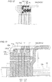
- connection portion 342b of one lead wire portion 34 and the connection portion 35a of another lead wire portion 35 among the plurality of concentrically wound coils 30 are connected on the outer side with respect to the peak portions T1 disposed on the outermost periphery, as viewed from the axial direction. Further, as illustrated in FIG. 1 , the connection portion 342b and the connection portion 35a are connected (welded) on the radially outer side of the stator core 10 while the connection portion 342b and the connection portion 35a are arranged in the circumferential direction.
- the concentrically wound coils 30 are continuous coils configured such that the connection portion 342b of one lead wire portion 34 on the radially inner side and the connection portion 35a of another lead wire portion 35 on the radially outer side among the plurality of concentrically wound coils 30 need to be connected (welded).
- the bent portion 34a is disposed on the stator core 10 side with respect to the peak portions T1 in the axial direction, in a space between the peak portions T1 that are closest to the extension portion 34c in the radial direction and that are adjacent in the circumferential direction.
- the lead wire portion 34 is bent on the axially inner side, and therefore it is possible to prevent an increase in the axial size of the coil end portion 21a accordingly. As a result, it is possible to prevent an increase in the axial size of the stator 100.
- the axial size of the stator 100 depends on the position of the bent portion 34a of the lead wire portion 34. That is, the end-side portion 34b of the lead wire portion 34 can be disposed closer to the axial end face 10b side of the stator core 10 depending on how (where) the bent portion 34a is bent. Therefore, in order to prevent an increase in the axial size of the stator 100, it is especially important to lower the position of the bent portion 34a (locate the bent portion 34a closer to the end face 10b side).
- At least a part of the bent portion 34a is disposed in the valley portion V (a low position) between the peak portions T1 such that the end-side portion 34b of the lead wire portion 34 is located closer to the axial end face 10b side of the stator core 10, thereby preventing an increase in the axial size of the stator 100.
- the efficiency (the ratio of mechanical output power to electrical input power) of the motor using the stator 100 according to the present embodiment can be improved.
- the circumferential width portion 34d of the bent portion 34a is disposed not to overlap the peak portions T1 as viewed from the radially inner side.
- at least a part of the bent portion 34a can easily be disposed in the valley portion V closest to the extension portion 34c in the radial direction.
- the coil end portion 21a includes the valley portions V each disposed between the peak portions T1 arranged in the circumferential direction, and the bent portions 34a are disposed in the valley portions V.
- the bend of the lead wire portion 34 starts in the valley portion V on the axially inner side with respect to the peak portions T1, and therefore the bent portion 34a can easily be disposed between the peak portions T1 arranged in the circumferential direction, so as to overlap the peak portions T1 as viewed from the circumferential direction.
- the bent portion 34a is bent from the innermost peripheral side of the stator core 10 to the radially outer side, and is disposed between the peak portions T1 located on the innermost peripheral side.
- the lead wire portion 34 can be bent to the radially outer side while preventing the bent portion 34a and the peak portions T1 from coming into contact with each other.
- the bent portion 34a is disposed between the peak portions T1 arranged in the circumferential direction, while being spaced apart from the peak portions T1.
- the bent portion 34a is disposed between the peak portions T1 arranged in the circumferential direction so as to overlap the peak portions T1
- the lead wire portion 34 includes the end-side portion 34b extending radially outward while being spaced apart from the peak portions T1 so as to be continuous from the bent portion 34a that is disposed apart from the peak portions T1.
- both the bent portion 34a and the end-side portion 34b are spaced apart from the peak portions T1. Therefore, it is possible to more effectively prevent damage to the rectangular conductor due to contact between the lead wire portion 34 and the peak portions T1.
- the distance L between the end-side portion 34b and the peak portions T1 is less than the inner curvature radius r of the bent portion 34a.
- the bent portion 34a is disposed between the peak portions T1 arranged in the circumferential direction, so as to overlap the peak portions T1, as viewed from the circumferential direction. Therefore, it is possible to restrain the axial size of the entire coil end portion 21a.
- the portion 341b of the end-side portion 34b is disposed on the axially outer side of the peak portions T1, and is disposed to extend substantially linearly.
- the portion 341b of the end-side portion 34b is formed in a shape (such as a bent shape and a curved shape) other than the substantially linear shape, the size of the portion 341b can be reduced. As a result, it is possible to further reduce the required length of the rectangular conductor, and to further improve the efficiency of the motor.
- connection portion 342b of each of the plurality of lead wire portions 34 is disposed on the outer side with respect to the peak portions T1 disposed on the outermost periphery, as viewed from the axial direction.
- work for connecting (work for welding) the connection portion 342b of each lead wire portion 34 on the outer peripheral side of the stator core 10, which is a relatively large space. Accordingly, it is possible to perform work for connecting (work for welding) the connection portion 342b while preventing interference between the connection portion 342b and other parts.
- the concentrically wound coil 30 is formed by winding a rectangular conductor, and the bent portion 34a is formed by flatwise bending that bends the long side of the cross-section of the rectangular conductor.
- the bent portion 34a is formed by flatwise bending that allows relatively easy bending compared to edgewise bending, the bent portion 34a can easily be formed.
- a method of manufacturing the stator 100 according to the present embodiment will be described with reference to FIG. 15 .
- the in-slot conductor portions 31 of all the concentrically wound coils 30 forming an annular cage-shaped coil assembly are pressed toward radially outer side.
- all the concentrically wound coils 30 are pressed radially from the radially inner side toward the radially outer side, so that the concentrically wound coils 30 are attached to the stator core 10.
- the lead wire portion 34 of each concentrically wound coil 30 is bent.
- This bending is performed such that the radially-inner-side lead wire portion 34 extends radially outward across the lead-side coil end conductor portion 32 so as to connect the distal end (the connection portion 342b) of the radially-inner-side lead wire portion 34 of one concentrically wound coil 30 of two concentrically wound coils 30 disposed apart from each other by a predetermined distance in the circumferential direction to the distal end (the connection portion 35a) of the radially-outer-side lead wire portion 35 of the other concentrically wound coil 30.
- the radially-inner-side lead wire portion 34 is formed to include the extension portion 34c, the bent portion 34a, the portion 341b, and the connection portion 342b that are substantially concentrically formed ( FIG. 15 (A) ).
- the inner-diameter side lead wire portion 34 is bent flatwise by the stator manufacturing apparatus (not illustrated), using the bent portion 34a (the portion surrounded by the dashed line in FIG. 15(B) ) extending substantially axially as a fulcrum, such that a portion (more specifically, the portion 341b and the connection portion 342b) located on the distal end side with respect to the bent portion 34a is laid radially outward ( FIG.
- a portion (more specifically, the extension portion 34c, the bent portion 34a, the portion 341b, and the connection portion 342b, that is, the entire radially-inner-side lead wire portion 34) located on the distal end side with respect to the bent part A1 is bent edgewise (in the counterclockwise direction in FIG. 15 ) so as to come closer to the axial end face of the stator core 10 while extending in the circumferential direction of the stator core 10 ( FIG. 15(C) ).
- at least a part of the bent portion 34a is disposed in the valley portion V closest to the extension portion 34c in the radial direction ( FIGS. 13 and 14 ).
- a concentrically wound coil formed of a rectangular conductor is used.
- the present invention is not limited thereto.
- coils other than a concentrically wound coil formed of a rectangular conductor may be used.
- a coil may be formed of a conductor such as a round conductor and a conductor with an elliptical cross-sectional shape.
- the coils are continuous coils (concentrically wound coils) configured such that one lead wire portion on the radially inner side and another lead wire portion on the radially outer side among the plurality of concentrically wound coils need to be connected (welded).
- the present invention is not limited thereto.
- the coils may be wave wound coils 50 (continuous coils) (see FIG. 16 ) configured such that one lead wire portion on the radially inner side and another lead wire portion on the radially outer side among the plurality of coils need to be connected (welded).
- the wave wound coil 50 includes in-slot portions 51a, 51b, and 51c accommodated in different slots 13, a coil end portion 52a connecting the in-slot portions 51a and 51b to each other on one axial side, and a coil end portion 52b connecting the in-slot portions 51b and 51c to each other on the other axial side. That is, the wave wound coil 50 is formed of a single conductor wire 60 without being joined by welding or the like.
- the coil end portions 52a and 52b include, respectively, offset portions 53a and 53b, each being radially offset by a width of the single conductor wire 60.
- the wave wound coils 50 are an example of "coils" in the appended claims.
- a concentrically wound coil formed by winding a rectangular conductor in a plurality of turns is used.
- the present invention is not limited thereto.
- a coil formed by winding a rectangular conductor (or a conductor other than a rectangular conductor) in a single turn may be used.
- a stator-core-side (Z2-direction-side) part of the bent portion is disposed in a valley portion, as viewed from the circumferential direction.
- the present invention is not limited thereto.
- the entire bent portion may be disposed in a valley portion.
- the bent portion is disposed between the peak portions located on the innermost peripheral side.
- the present invention is not limited thereto.
- the bent portion may be disposed between the peak portions located on the outer peripheral side with respect to the peak portions located on the innermost peripheral side, in addition to the peak portions located on the innermost peripheral side.
- the end-side portion (the portion 341b, see FIG. 9 ) continuous from the bent portion extends to cross (to cross at an angle less than 90 degrees) the circumferential direction, as viewed from the axial direction.
- the present invention is not limited thereto.
- the end-side portion continuous from the bent portion may extend orthogonally to the circumferential direction, as viewed from the axial direction.
- the bent portion is bent at an angle of approximately 90 degrees from the radially inner side to the radially outer side.
- the present invention is not limited thereto.
- the bent portion may be bent at an angle greater than 90 degrees, or at an angle less than 90 degrees in a manner not to come into contact with the peak portions.
- connection portion of one lead wire portion and a connection portion of another lead wire portion among the plurality of concentrically wound coils are connected (welded) on the radially outer side of the stator core.
- the present invention is not limited thereto.
- a connection portion of one lead wire portion and a connection portion of another lead wire portion among the plurality of concentrically wound coils may be connected (welded) on the radially inner side of the stator core.
- the extension portion on the radially innermost side is disposed in a valley portion on the radially inner side.
- the present invention is not limited thereto.
- the extension portion on the radially outermost side may be disposed in a valley portion on the radially outer side.
- the bent portion of the lead wire portion is disposed in a valley portion so as to overlap the peak portions on the radially outer side as viewed from the circumferential direction, and a circumferential width portion of the bent portion is disposed not to overlap the peak portions as viewed from the radially outer side.
Abstract
Description
- The present invention relates to a stator.
- There is known a stator that is provided with a coil formed of a plurality of coil units. This type of stator is disclosed in, for example, Japanese Patent Application Publication No.
2012-125043 JP 2012-125043 A - In a stator disclosed in
JP 2012-125043 A - In a conventional stator such as that disclosed in
JP 2012-125043 A FIGS. 8 and12 ofJP 2012-125043 A - Patent Document 1: Japanese Patent Application Publication No.
2012-125043 - However, the conventional stator such as that disclosed in
JP 2012-125043 A - The present invention has been made to solve the above-described problem, and an object of the present invention is to provide a stator that can be prevented from being increased in the axial size.
- In order to achieve the above object, a stator according to one aspect of the present invention includes: a stator core having a plurality of slots; and a coil unit formed of a plurality of coils disposed in the plurality of slots; wherein the coil unit includes a coil end portion projecting from an axial end face of the stator core; wherein the coil end portion includes a plurality of peak portions projecting axially outward and arranged in a circumferential direction, and a plurality of lead wire portions for supplying electric power to the coils; and wherein each of the lead wire portions includes an extension portion extending at least in an axial direction, and a bent portion that is bent at least from the axial direction to a radial direction, at least a part of the bent portion being disposed on a stator core side with respect to the peak portions in the axial direction, in a space between the peak portions that are closest to the extension portion in the radial direction and that are adjacent to each other in the circumferential direction.
- In the stator according to the one aspect of the present invention, as described above, at least a part of the bent portion is disposed on a stator core side with respect to the peak portions in the axial direction, in a space between the peak portions that are closest to the extension portion in the radial direction and that are adjacent to each other in the circumferential direction. Thus, compared to the case where the bent portion is bent on the axially outer side with respect to the peak portions of the coil end portion, the lead wire portion is bent on the axially inner side, and therefore it is possible to prevent an increase in the axial size of the coil end portion. As a result, it is possible to prevent an increase in the axial size of the stator.
- According to the present invention, as described above, it is possible to prevent an increase in the axial size.
-
- [
FIG. 1] FIG. 1 is a top view of a stator according to an embodiment of the present invention. - [
FIG. 2] FIG. 2 is a side view of the stator according to the embodiment of the present invention. - [
FIG. 3] FIG. 3 is a perspective view of the stator according to the embodiment of the present invention. - [
FIG. 4] FIG. 4 is a side view of coils as viewed from the radially inner side according to the embodiment of the present invention. - [
FIG. 5] FIG. 5 is a perspective view of a concentrically wound coil according to the embodiment of the present invention. - [
FIG. 6] FIG. 6 is a side view of the concentrically wound coil according to the embodiment of the present invention. - [
FIG. 7] FIG. 7 is a diagram illustrating the concentrically wound coil as viewed from the upper side according to the embodiment of the present invention. - [
FIG. 8] FIG. 8 is a partially enlarged view ofFIG. 4 (the side view of the coils as viewed from the radially inner side) according to the embodiment of the present invention. - [
FIG. 9] FIG. 9 is an enlarged view of the coils as viewed from the upper side according to the embodiment of the present invention. - [
FIG. 10] FIG. 10 is a perspective view of the coils as viewed from the radially inner side according to the embodiment of the present invention. - [
FIG. 11] FIG. 11 is a cross-sectional view taken along line 200 - 200 inFIG. 9 . - [
FIG. 12] FIG. 12 is a cross-sectional view taken along line 300 - 300 inFIG. 9 . - [
FIG. 13] FIG. 13 is a schematic diagram of peak portions and a bent portion as viewed from the circumferential direction. - [
FIG. 14] FIG. 14 is a schematic diagram of the peak portions and the bent portion as viewed from the radially outer side. - [
FIG. 15] FIG. 15 is a diagram illustrating a method of manufacturing the stator according to the embodiment of the present invention. - [
FIG. 16] FIG. 16 is a perspective view of a wave wound coil according to a modification of the embodiment of the present invention. - An embodiment of the present invention will be described with reference to the drawings.
- The structure of a
stator 100 according to the present embodiment will be described with reference toFIGS. 1 to 14 . In the following description, the "axial direction", "radial direction", and "circumferential direction" refer to the directions with respect to astator core 10. Further, the "axially outer side" refers to the side away from thestator core 10 in the axial direction. The "axially inner side" refers to the side toward thestator core 10 in the axial direction. Further, the "radially outer side" refers to the side toward which the diameter of thestator core 10 increases in the radial direction. The "radially inner side" refers to the side toward which the diameter of thestator core 10 decreases in the radial direction. - As illustrated in
FIGS. 1 to 3 , thestator 100 includes thestator core 10 and a coil unit 20 (concentrically wound coils 30). The concentricallywound coils 30 are an example of "coils" in the appended claims. - The
stator core 10 is formed in an annular shape (a hollow cylindrical shape). Note that theannular stator core 10 includes a stator core that is formed by assembling split cores. An inner diameter space for accommodating a rotor (not illustrated) is formed on the radially inner side of thestator core 10. Thestator core 10 is formed by axially stacking a plurality of electrical steel plates coated with an insulating material. - As illustrated in
FIG. 3 , thestator core 10 includes aback yoke 11 formed in an annular shape, and a plurality ofteeth 12 extending radially inward from theback yoke 11. The plurality ofteeth 12 are disposed on thestator core 10 at substantially equal angular intervals in the circumferential direction. Further,slots 13 are formed between theadjacent teeth 12. - The
stator core 10 is provided withear portions 14 for fixing thestator 100 to a motor case (not illustrated). Theear portions 14 are formed to project outward from the radially outer end face (an outerperipheral face 10a) of thestator core 10. The plurality ofear portions 14 are provided in the circumferential direction. For example, threeear portions 14 are disposed at substantially equal angular intervals. Eachear portion 14 is provided with athrough hole 14a axially extending therethrough. Thestator 100 is fixed to the motor case by threading bolts (not illustrated) into the motor case through the throughholes 14a of theear portions 14. - As illustrated in
FIG. 4 , thecoil unit 20 is formed of the plurality of concentricallywound coils 30 that are inserted in the plurality ofslots 13. Thecoil unit 20 is formed by arranging the plurality of concentrically wound coils 30 in the circumferential direction. Thecoil unit 20 has an annular cage shape. In the case where thestator 100 is applied to a three-phase AC motor, eachconcentrically wound coil 30 forms one of a U-phase coil, a V-phase coil, and a W-phase coil. - The
coil unit 20 includescoil end portions 21 projecting from respective axial end faces 10b (seeFIGS. 2 and3 ) of thestator core 10. Thecoil end portions 21 include acoil end portion 21 a disposed on the lead side (power supply side) and acoil end portion 21b disposed on the side opposite to the lead side. - The
coil end portion 21a disposed on the lead side includes a plurality of peak portions T1 projecting axially outward (to a Z1 direction) and arranged in the circumferential direction. Thecoil end portion 21a further includes a plurality of lead wire portions 34 (lead wire portions 34 of the concentrically wound coils 30 described below) for supplying electric power to the concentrically wound coils 30. Valley portions V are disposed between the peak portions T1 that are arranged in the circumferential direction. Meanwhile, thecoil end portion 21b disposed on the side opposite to the lead side includes a plurality of peak portions T2 projecting axially outward (to a Z2 direction) and arranged in the circumferential direction. - The peak portions T1 are the axially outermost portions, except the lead wire portions 34 (35) described below, in the
coil end portion 21a projecting axially outward with respect to thestator core 10. The plurality of peak portions T1 are arranged on the same diameter in the circumferential direction, and also arranged in the radial direction. Each peak portion T1 is included in a portion (acrank portion 32a described below) radially offsetting the concentrically wound coils 30 disposed in theslots 13 that are adjacent to each other in the circumferential direction. - Further, each valley portion V is disposed in the circumferential direction between the peak portions T1 that are adjacent in the circumferential direction, and is a gap portion on the
stator core 10 side (a lower portion) with respect to the peak portions T1 in the axial direction, in thecoil end portion 21 a projecting axially outward with respect to thestator core 10. The plurality of valley portions V are arranged on the same diameter in the circumferential direction, and also arranged in the radial direction. - As illustrated in
FIGS. 5 to 7 , theconcentrically wound coil 30 is formed by winding a rectangular conductor having a substantially rectangular cross-sectional shape. More specifically, theconcentrically wound coil 30 is formed by edgewise bending that bends the short side of the cross-section of the rectangular conductor, such that rectangular conductor is wound in a substantially hexagonal shape. The rectangular conductor is made of a highly conductive metal (for example, copper, aluminum, and the like). Note that the corners of the cross-section of the rectangular conductor may be chamfered (rounded) into round shapes. Further, the plurality of concentrically wound coils 30 are disposed on thestator core 10 in the circumferential direction (seeFIG. 4 ). Note that the upper end (thecrank portion 32a described below) of the substantially hexagonal concentrically woundcoil 30 forms the peak portion T1. - The
concentrically wound coil 30 includes in-slot conductor portions 31 accommodated in theslots 13, lead-side coilend conductor portions 32 disposed on the lead side (the power supply side, the Z1 direction side), and non-lead-side coilend conductor portions 33 disposed on the side (the Z2 direction side) opposite to the lead side. - Further, the lead-side coil
end conductor portions 32 each include thecrank portion 32a formed in a crank shape that is bent stepwise in the radial direction of thestator core 10, and acurved portion 32b that is curved in an arc shape along the arc of theannular stator core 10. Similar to the lead-side coilend conductor portions 32, the non-lead-side coilend conductor portions 33 each include acrank portion 33a and acurved portion 33b. - Further, as illustrated in
FIG. 8 , thecrank portions 32a of the respective plurality of concentrically wound coils 30 form the plurality of peak portions T1 of thecoil end portion 21a that project axially outward and that are arranged in the circumferential direction. Further, the valley portion V is formed between the peak portion T1 of oneconcentrically wound coil 30 and the peak portion T1 of anotherconcentrically wound coil 30 that are arranged in the circumferential direction. The peak portions T1 and the valley portions V are alternately disposed in the circumferential direction throughout the circumference of thecoil end portion 21a. - Further, as illustrated in
FIG. 5 , thelead wire portion 34 that is bent from the radially inner side to the radially outer side (the C1 direction side) is provided at one of the winding start portion and the winding end portion of theconcentrically wound coil 30. Meanwhile, alead wire portion 35 that is bent from the outer peripheral side of theconcentrically wound coil 30 to the radially outer side is provided at the other one of the winding start portion and the winding end portion of theconcentrically wound coil 30. Thelead wire portion 34 and thelead wire portion 35 are provided in each of the plurality of concentrically wound coils 30. - Each of the
lead wire portions 34 includes abent portion 34a that is bent from the radially inner side (the C2 direction side) to the radially outer side of thestator core 10. More specifically, the rectangular conductor (the in-slot conductor portion 31) formed to extend in the axial direction (a Z direction) is bent on the axially outer side (at a point A1) of theend face 10b of thestator core 10 to cross the axial direction. Then, the rectangular conductor is bent again at a point A2 to extend in the axial direction (the Z direction), and is bent at an angle of approximately 90 degrees at a point A3 from the radially inner side to the radially outer side of thestator core 10. Thus, thebent portion 34a is formed. - Further, an
extension portion 34c extending at least in the axial direction is provided between the in-slot conductor portion 31 and thebent portion 34a. More specifically, theextension portion 34c is provided to extend axially outward to cross the Z direction. - That is, as illustrated in
FIGS. 8 and13 , thelead wire portion 34 includes theextension portion 34c disposed on the lead side and projecting at least axially outward from theaxial end face 10b of thestator core 10, and an end-side portion 34b extending at least in the radial direction on the axially outer side with respect to the stator core 10 (note that the end-side portion 34b may extend not only in the radial direction, but also in the circumferential direction). Thelead wire portion 34 further includes, between theextension portion 34c and the end-side portion 34b, thebent portion 34a that is bent from the axial direction to at least the radial direction such that theextension portion 34c extending in the axial direction is connected to the end-side portion 34b extending in the radial direction. Thebent portion 34a extends from a bend start point to the end point. The bend start point refers to a point where theextension portion 34c starts to bend at least in the radial direction, and the bend end point of thebent portion 34a refers to the end-side portion 34b extending in the radial direction. Theextension portion 34c extends in the axial direction or the circumferential direction, but does not extend in the radial direction. Accordingly, since theextension portion 34c does not extend in the radial direction, it is possible to prevent an increase in the radial size while preventing an increase in the axial size of thestator 100. - The
extension portion 34c projects in the axial direction on the radially innermost side or the radially outermost side, in thecoil end portion 21a projecting from thestator core 10. The end-side portion 34b extends at least in the radial direction, along the plurality of peak portions T1 on the axially outer side with respect to the peak portions T1, or along the core end face (theaxial end face 10b). The end-side portion 34b is disposed apart from the peak portions T1 in the axial direction. Note that the end-side portion 34b may be in contact with the peak portions T1, instead of being spaced apart. The end-side portion 34b extends parallel to the plurality of peak portions T1 or the core end face (theaxial end face 10b) in the radial direction. - In the present embodiment, as illustrated in
FIGS. 8 to 13 , at least a part of thebent portion 34a is disposed on thestator core 10 side (the side closer to theaxial end face 10b of the stator core 10) with respect to the peak portions T1 in the axial direction, in a space between the peak portions T1 that are closest to theextension portion 34c in the radial direction and that are adjacent in the circumferential direction (a D direction, seeFIG. 13 ). That is, at least a part of thebent portion 34a is disposed in the valley portion V closest to theextension portion 34c in the radial direction. Further, thebent portion 34a is disposed between the peak portions T1 arranged in the circumferential direction (seeFIGS. 8 to 10 ), so as to overlap the peak portions T1 (seeFIGS. 11 to 13 ), as viewed from the circumferential direction. More specifically, as illustrated inFIG. 8 , thebent portion 34a is disposed between the two peak portions T1 arranged in the circumferential direction, as viewed from the radially inner side. Further, as illustrated inFIGS. 11 to 13 , thebent portion 34a is disposed to overlap the peak portions T1, as viewed from the circumferential direction. More specifically, thebent portion 34a is disposed to overlap the peak portions T1 as viewed from one side in the circumferential direction (seeFIG. 11 ), and as viewed from the other side in the circumferential direction (seeFIG. 12 ). - Further, as illustrated in
FIG. 8 , theextension portion 34c on the radially innermost side is disposed in the valley portion V on the radially inner side, and thebent portion 34a of thelead wire portion 34 is disposed in the valley portion V to overlap the peak portions T1 on the radially inner side as viewed from the circumferential direction. Further, in the present embodiment, acircumferential width portion 34d of thebent portion 34a is disposed not to overlap the peak portions T1 as viewed from the radially inner side. - Further, as illustrated in
FIG. 13 , abend start point 341a of thebent portion 34a is disposed on thestator core 10 side (the Z2 direction side) with respect to the peak portions T1 (a height position h of the peak portions T1 from theend face 10b of the stator core 10), as viewed from the circumferential direction. - Further, in the present embodiment, as illustrated in
FIG. 14 , thebent portion 34a is disposed in the valley portion V between the peak portions T1 arranged in the circumferential direction. More specifically, as viewed from the radially outer side, a stator-core-10-side (Z2-direction-side) portion of thebent portion 34a (aninner portion 342a of thebent portion 34a described below) is disposed in the valley portion V. - Further, in the present embodiment, as illustrated in
FIG. 14 , thebent portion 34a is bent from the innermost peripheral side of thestator core 10 to the radially outer side, and is disposed between the peak portions T1 (peak portions T1a) located on the innermost peripheral side. More specifically, as illustrated inFIG. 13 , thebent portion 34a is disposed such that theinner portion 342a of thebent portion 34a overlaps a corner portion T1b (the corner portion T1b on the radially inner side and the axially outer side) of the peak portion T1 disposed on the innermost peripheral side, as viewed from the circumferential direction. - Further, in the present embodiment, as illustrated in
FIG. 14 , thebent portion 34a is disposed between the peak portions T1 arranged in the circumferential direction, while being spaced apart from the peak portions T1. More specifically, as viewed from the axially outer side, thebent portion 34a is disposed between the peak portions T1 (in the valley portion V), while being spaced apart (being disposed with a space S) from the peak portions T1 arranged in the circumferential direction. Note that thebent portion 34a is disposed between the peak portions T1 (in the valley portion V), while being disposed with the space S in both the circumferential direction and the radial direction. - Further, in the present embodiment, the
bent portion 34a is formed by flatwise bending that bends the long side of the cross-section of the rectangular conductor. More specifically, as illustrated inFIG. 5 , the in-slot conductor portions 31, the lead-side coilend conductor portions 32, and the non-lead-side coilend conductor portions 33 are formed by edgewise bending that bends the short side of the cross-section of the rectangular conductor. Further, the rectangular conductor is bent edgewise at the point A1 and the point A2, and then bent flatwise at the point A3 from the radially inner side to the radially outer side, so that thebent portion 34a is formed. - Further, in the present embodiment, as illustrated in
FIG. 9 , thelead wire portion 34 includes the end-side portion 34b extending radially outward while being spaced apart (being spaced with a distance L, seeFIG. 13 ) from the peak portions T1 so as to be continuous from thebent portion 34a that is disposed apart from the peak portions T1. The end-side portion 34b includes aportion 341b extending to cross (to cross at an angle less than 90 degrees) the circumferential direction, as viewed from the axial direction, and aconnection portion 342b formed by bending the rectangular conductor at a point A4 and extending in the radial direction. A portion (theportion 341b) of the end-side portion 34b is disposed on the axially outer side of the peak portions T1, and is disposed to extend substantially linearly. Theconnection portion 342b is an example of a "distal end portion". - Further, in the present embodiment, as illustrated in
FIG. 13 , the distance L between the end-side portion 34b and the peak portions T1 is less than an inner curvature radius r of thebent portion 34a. Thus, by bending thelead wire portion 34 from the radially inner side to the radially outer side, thebent portion 34a is disposed between the peak portions T1 arranged in the circumferential direction, so as to overlap the peak portions T1, as viewed from the circumferential direction. - As illustrated in
FIG. 5 , in thelead wire portion 35, the rectangular conductor (the in-slot conductor portion 31) formed to extend in the axial direction (the Z direction) is bent on the axially outer side (at a point B1) of theend face 10b of thestator core 10 to extend in the circumferential direction. Then, the rectangular conductor is bent again at a point B2 to extend in the axial direction (the Z direction), and is bent radially outward at an angle of approximately 90 degrees at a point B3. Thus, aconnection portion 35a is formed. - In the present embodiment, as illustrated in
FIG. 9 , theconnection portion 342b of each of the plurality oflead wire portions 34 is configured to be disposed on the outer side with respect to the peak portions T1 (T1c) disposed on the outermost periphery, as viewed from the axial direction. Theconnection portion 35a of each of the plurality oflead wire portions 35 is configured to be disposed on the outer side with respect to the peak portions T1 disposed on the outermost periphery, as viewed from the axial direction. As illustrated inFIG. 9 , theconnection portion 342b of onelead wire portion 34 and theconnection portion 35a of anotherlead wire portion 35 among the plurality of concentrically wound coils 30 are connected on the outer side with respect to the peak portions T1 disposed on the outermost periphery, as viewed from the axial direction. Further, as illustrated inFIG. 1 , theconnection portion 342b and theconnection portion 35a are connected (welded) on the radially outer side of thestator core 10 while theconnection portion 342b and theconnection portion 35a are arranged in the circumferential direction. That is, the concentrically wound coils 30 are continuous coils configured such that theconnection portion 342b of onelead wire portion 34 on the radially inner side and theconnection portion 35a of anotherlead wire portion 35 on the radially outer side among the plurality of concentrically wound coils 30 need to be connected (welded). - According to the present embodiment, the following effects can be obtained.
- In the present embodiment, as described above, at least a part of the
bent portion 34a is disposed on thestator core 10 side with respect to the peak portions T1 in the axial direction, in a space between the peak portions T1 that are closest to theextension portion 34c in the radial direction and that are adjacent in the circumferential direction. Thus, compared to the case where thebent portion 34a is bent at the position that is further from the axially outer side than the peak portions T1 of thecoil end portion 21 a are, thelead wire portion 34 is bent on the axially inner side, and therefore it is possible to prevent an increase in the axial size of thecoil end portion 21a accordingly. As a result, it is possible to prevent an increase in the axial size of thestator 100. That is, the axial size of thestator 100 depends on the position of thebent portion 34a of thelead wire portion 34. That is, the end-side portion 34b of thelead wire portion 34 can be disposed closer to theaxial end face 10b side of thestator core 10 depending on how (where) thebent portion 34a is bent. Therefore, in order to prevent an increase in the axial size of thestator 100, it is especially important to lower the position of thebent portion 34a (locate thebent portion 34a closer to theend face 10b side). Accordingly, in the present embodiment, at least a part of thebent portion 34a is disposed in the valley portion V (a low position) between the peak portions T1 such that the end-side portion 34b of thelead wire portion 34 is located closer to theaxial end face 10b side of thestator core 10, thereby preventing an increase in the axial size of thestator 100. - Further, since the
coil end portion 21a is prevented from being increased in the axial size, the total length of the rectangular conductor forming theconcentrically wound coil 30 is reduced. Therefore, the required length of the rectangular conductor can be reduced. Further, since the total length of the rectangular conductor is reduced, the copper loss can be reduced. Therefore, the efficiency (the ratio of mechanical output power to electrical input power) of the motor using thestator 100 according to the present embodiment can be improved. - Further, in the present embodiment, as described above, the
circumferential width portion 34d of thebent portion 34a is disposed not to overlap the peak portions T1 as viewed from the radially inner side. Thus, at least a part of thebent portion 34a can easily be disposed in the valley portion V closest to theextension portion 34c in the radial direction. - Further, in the present embodiment, as described above, the
coil end portion 21a includes the valley portions V each disposed between the peak portions T1 arranged in the circumferential direction, and thebent portions 34a are disposed in the valley portions V. Thus, the bend of thelead wire portion 34 starts in the valley portion V on the axially inner side with respect to the peak portions T1, and therefore thebent portion 34a can easily be disposed between the peak portions T1 arranged in the circumferential direction, so as to overlap the peak portions T1 as viewed from the circumferential direction. - Further, in the present embodiment, as described above, the
bent portion 34a is bent from the innermost peripheral side of thestator core 10 to the radially outer side, and is disposed between the peak portions T1 located on the innermost peripheral side. Thus, even in the case where the bend of thelead wire portion 34 starts at a height position lower than the height position h of the peak portions T1, thelead wire portion 34 can be bent to the radially outer side while preventing thebent portion 34a and the peak portions T1 from coming into contact with each other. - Further, in the present embodiment, as described above, the
bent portion 34a is disposed between the peak portions T1 arranged in the circumferential direction, while being spaced apart from the peak portions T1. Thus, even in the case where thebent portion 34a is disposed between the peak portions T1 arranged in the circumferential direction so as to overlap the peak portions T1, it is possible to prevent thebent portion 34a and the peak portions T1 from coming into contact with each other. Therefore, it is possible to prevent damage to the rectangular conductor due to contact between thebent portion 34a and the peak portions T1. - Further, in the present embodiment, as described above, the
lead wire portion 34 includes the end-side portion 34b extending radially outward while being spaced apart from the peak portions T1 so as to be continuous from thebent portion 34a that is disposed apart from the peak portions T1. Thus, both thebent portion 34a and the end-side portion 34b are spaced apart from the peak portions T1. Therefore, it is possible to more effectively prevent damage to the rectangular conductor due to contact between thelead wire portion 34 and the peak portions T1. - Further, in the present embodiment, as described above, the distance L between the end-
side portion 34b and the peak portions T1 is less than the inner curvature radius r of thebent portion 34a. Thus, thebent portion 34a is disposed between the peak portions T1 arranged in the circumferential direction, so as to overlap the peak portions T1, as viewed from the circumferential direction. Therefore, it is possible to restrain the axial size of the entirecoil end portion 21a. - Further, in the present embodiment, as described above, the
portion 341b of the end-side portion 34b is disposed on the axially outer side of the peak portions T1, and is disposed to extend substantially linearly. Thus, compared to the case where theportion 341b of the end-side portion 34b is formed in a shape (such as a bent shape and a curved shape) other than the substantially linear shape, the size of theportion 341b can be reduced. As a result, it is possible to further reduce the required length of the rectangular conductor, and to further improve the efficiency of the motor. - Further, in the present embodiment, as described above, the
connection portion 342b of each of the plurality oflead wire portions 34 is disposed on the outer side with respect to the peak portions T1 disposed on the outermost periphery, as viewed from the axial direction. Thus, it is possible to perform work for connecting (work for welding) theconnection portion 342b of eachlead wire portion 34 on the outer peripheral side of thestator core 10, which is a relatively large space. Accordingly, it is possible to perform work for connecting (work for welding) theconnection portion 342b while preventing interference between theconnection portion 342b and other parts. - Further, in the present embodiment, as described above, the
concentrically wound coil 30 is formed by winding a rectangular conductor, and thebent portion 34a is formed by flatwise bending that bends the long side of the cross-section of the rectangular conductor. Thus, since thebent portion 34a is formed by flatwise bending that allows relatively easy bending compared to edgewise bending, thebent portion 34a can easily be formed. - A method of manufacturing the
stator 100 according to the present embodiment will be described with reference toFIG. 15 . - First, the in-
slot conductor portions 31 of all the concentrically wound coils 30 forming an annular cage-shaped coil assembly are pressed toward radially outer side. Thus, all the concentrically wound coils 30 are pressed radially from the radially inner side toward the radially outer side, so that the concentrically wound coils 30 are attached to thestator core 10. Then, thelead wire portion 34 of eachconcentrically wound coil 30 is bent. This bending is performed such that the radially-inner-sidelead wire portion 34 extends radially outward across the lead-side coilend conductor portion 32 so as to connect the distal end (theconnection portion 342b) of the radially-inner-sidelead wire portion 34 of oneconcentrically wound coil 30 of two concentrically wound coils 30 disposed apart from each other by a predetermined distance in the circumferential direction to the distal end (theconnection portion 35a) of the radially-outer-sidelead wire portion 35 of the other concentrically woundcoil 30. - More specifically, before the bending by a stator manufacturing apparatus (not illustrated), the radially-inner-side
lead wire portion 34 is formed to include theextension portion 34c, thebent portion 34a, theportion 341b, and theconnection portion 342b that are substantially concentrically formed (FIG. 15 (A) ). First, the inner-diameter sidelead wire portion 34 is bent flatwise by the stator manufacturing apparatus (not illustrated), using thebent portion 34a (the portion surrounded by the dashed line inFIG. 15(B) ) extending substantially axially as a fulcrum, such that a portion (more specifically, theportion 341b and theconnection portion 342b) located on the distal end side with respect to thebent portion 34a is laid radially outward (FIG. 15(B) ). Then, using a bent part A1 (a portion surrounded by the dashed line inFIG. 15(C) ) as a fulcrum, a portion (more specifically, theextension portion 34c, thebent portion 34a, theportion 341b, and theconnection portion 342b, that is, the entire radially-inner-side lead wire portion 34) located on the distal end side with respect to the bent part A1 is bent edgewise (in the counterclockwise direction inFIG. 15 ) so as to come closer to the axial end face of thestator core 10 while extending in the circumferential direction of the stator core 10 (FIG. 15(C) ). In this step, at least a part of thebent portion 34a is disposed in the valley portion V closest to theextension portion 34c in the radial direction (FIGS. 13 and14 ). - The presently disclosed embodiment should be considered in all respects to be illustrative and not restrictive. The scope of the invention is indicated by the appended claims rather than the foregoing description, and all variations (modifications) which come within the meaning and range of equivalents thereof are intended to be embraced therein.
- For example, in the above embodiment, a concentrically wound coil formed of a rectangular conductor is used. However, the present invention is not limited thereto. For example, coils other than a concentrically wound coil formed of a rectangular conductor may be used. More specifically, a coil may be formed of a conductor such as a round conductor and a conductor with an elliptical cross-sectional shape.
- Further, in the above embodiment, the coils are continuous coils (concentrically wound coils) configured such that one lead wire portion on the radially inner side and another lead wire portion on the radially outer side among the plurality of concentrically wound coils need to be connected (welded). However, the present invention is not limited thereto. For example, the coils may be wave wound coils 50 (continuous coils) (see
FIG. 16 ) configured such that one lead wire portion on the radially inner side and another lead wire portion on the radially outer side among the plurality of coils need to be connected (welded). - More specifically, as illustrated in
FIG. 16 , thewave wound coil 50 includes in-slot portions different slots 13, acoil end portion 52a connecting the in-slot portions coil end portion 52b connecting the in-slot portions wave wound coil 50 is formed of asingle conductor wire 60 without being joined by welding or the like. Thecoil end portions portions single conductor wire 60. The wave wound coils 50 are an example of "coils" in the appended claims. - Further, in the above embodiment, a concentrically wound coil formed by winding a rectangular conductor in a plurality of turns is used. However, the present invention is not limited thereto. For example, a coil formed by winding a rectangular conductor (or a conductor other than a rectangular conductor) in a single turn may be used.
- Further, in the above embodiment, a stator-core-side (Z2-direction-side) part of the bent portion is disposed in a valley portion, as viewed from the circumferential direction. However, the present invention is not limited thereto. For example, as long as the bent portion and the peak portions are not in contact with each other, the entire bent portion may be disposed in a valley portion.
- Further, in the above embodiment, the bent portion is disposed between the peak portions located on the innermost peripheral side. However, the present invention is not limited thereto. For example, the bent portion may be disposed between the peak portions located on the outer peripheral side with respect to the peak portions located on the innermost peripheral side, in addition to the peak portions located on the innermost peripheral side.
- Further, in the above embodiment, the end-side portion (the
portion 341b, seeFIG. 9 ) continuous from the bent portion extends to cross (to cross at an angle less than 90 degrees) the circumferential direction, as viewed from the axial direction. However, the present invention is not limited thereto. For example, the end-side portion continuous from the bent portion may extend orthogonally to the circumferential direction, as viewed from the axial direction. - Further, in the above embodiment, the bent portion is bent at an angle of approximately 90 degrees from the radially inner side to the radially outer side. However, the present invention is not limited thereto. For example, the bent portion may be bent at an angle greater than 90 degrees, or at an angle less than 90 degrees in a manner not to come into contact with the peak portions.
- Further, in the above embodiment, a connection portion of one lead wire portion and a connection portion of another lead wire portion among the plurality of concentrically wound coils are connected (welded) on the radially outer side of the stator core. However, the present invention is not limited thereto. For example, a connection portion of one lead wire portion and a connection portion of another lead wire portion among the plurality of concentrically wound coils may be connected (welded) on the radially inner side of the stator core.
- Further, in the above embodiment, the extension portion on the radially innermost side is disposed in a valley portion on the radially inner side. However, the present invention is not limited thereto. For example, the extension portion on the radially outermost side may be disposed in a valley portion on the radially outer side. In this case, the bent portion of the lead wire portion is disposed in a valley portion so as to overlap the peak portions on the radially outer side as viewed from the circumferential direction, and a circumferential width portion of the bent portion is disposed not to overlap the peak portions as viewed from the radially outer side.
-
- 10
- stator core
- 10b
- end face
- 13
- slot
- 20
- coil
- 21 a
- coil end portion
- 30
- concentrically wound coil (coil)
- 34
- lead wire portion
- 34a
- bent portion
- 34b
- end-side portion
- 34c
- extension portion
- 34d
- circumferential width portion
- 50
- wave wound coil
- 100
- stator
- 341b
- portion (of lead wire portion)
- 342b
- distal end portion (of lead wire portion)
- L
- distance
- r
- curvature radius
- T1
- peak portion
- V
- valley portion
Claims (8)
- A stator comprising:a stator core having a plurality of slots; anda coil unit formed of a plurality of coils disposed in the plurality of slots;wherein the coil unit includes a coil end portion projecting from an axial end face of the stator core;wherein the coil end portion includes a plurality of peak portions projecting axially outward and arranged in a circumferential direction, and a plurality of lead wire portions for supplying electric power to the coils; andwherein each of the lead wire portions includes an extension portion extending at least in an axial direction, and a bent portion that is bent at least from the axial direction to a radial direction, at least a part of the bent portion being disposed on a stator core side with respect to the peak portions in the axial direction, in a space between the peak portions that are closest to the extension portion in the radial direction and that are adjacent in the circumferential direction.
- The stator according to claim 1, wherein a circumferential width portion of the bent portion of each of the lead wire portions is disposed not to overlap the peak portions as viewed from the radial direction.
- The stator according to claim 1 or 2, wherein the bent portion is bent from an innermost peripheral side of the stator core to a radially outer side, and is disposed between the peak portions located on the innermost peripheral side.
- The stator according to any one of claims 1 to 3, wherein the bent portion is disposed between the peak portions arranged in the circumferential direction, while being spaced apart from the peak portions.
- The stator according to claim 4,
wherein each of the lead wire portions further includes an end-side portion extending radially outward while being spaced apart from the peak portions so as to be continuous from the bent portion that is disposed apart from the peak portions; and
wherein a distance between the end-side portion and the peak portions is less than an inner curvature radius of the bent portion. - The stator according to claim 5, wherein a portion of the end-side portion is disposed on an axially outer side of the peak portions, and is disposed to extend substantially linearly.
- The stator according to any one of claims 1 to 6, wherein a distal end portion of each of the plurality of lead wire portions is configured to be disposed on an outer side with respect to the peak portions disposed on an outermost periphery, as viewed from the axial direction.
- The stator according to any one of claims 1 to 7,
wherein each of the coils is formed by winding a rectangular conductor; and
wherein the bent portion is formed by flatwise bending that bends a long side of a cross-section of the rectangular conductor.
Applications Claiming Priority (3)
| Application Number | Priority Date | Filing Date | Title |
|---|---|---|---|
| JP2015119214 | 2015-06-12 | ||
| JP2015231410 | 2015-11-27 | ||
| PCT/JP2016/066987 WO2016199788A1 (en) | 2015-06-12 | 2016-06-08 | Stator |
Publications (3)
| Publication Number | Publication Date |
|---|---|
| EP3276798A1 true EP3276798A1 (en) | 2018-01-31 |
| EP3276798A4 EP3276798A4 (en) | 2018-04-25 |
| EP3276798B1 EP3276798B1 (en) | 2019-10-09 |
Family
ID=57503970
Family Applications (1)
| Application Number | Title | Priority Date | Filing Date |
|---|---|---|---|
| EP16807494.6A Active EP3276798B1 (en) | 2015-06-12 | 2016-06-08 | Stator |
Country Status (5)
| Country | Link |
|---|---|
| US (1) | US10892656B2 (en) |
| EP (1) | EP3276798B1 (en) |
| JP (1) | JP6516004B2 (en) |
| CN (1) | CN107615622B (en) |
| WO (1) | WO2016199788A1 (en) |
Cited By (1)
| Publication number | Priority date | Publication date | Assignee | Title |
|---|---|---|---|---|
| EP3829033A1 (en) * | 2019-11-28 | 2021-06-02 | Rolls-Royce plc | Stator winding arrangement |
Families Citing this family (1)
| Publication number | Priority date | Publication date | Assignee | Title |
|---|---|---|---|---|
| US10874513B2 (en) * | 2018-02-12 | 2020-12-29 | 4C Medical Technologies, Inc. | Expandable frames and paravalvular leak mitigation systems for implantable prosthetic heart valve devices |
Family Cites Families (10)
| Publication number | Priority date | Publication date | Assignee | Title |
|---|---|---|---|---|
| JP4301334B2 (en) | 2007-10-19 | 2009-07-22 | トヨタ自動車株式会社 | Rotating electric machine |
| JP5195403B2 (en) | 2008-12-25 | 2013-05-08 | トヨタ自動車株式会社 | Stator and coil cage |
| WO2012049759A1 (en) | 2010-10-14 | 2012-04-19 | トヨタ自動車株式会社 | Motor |
| JP5560176B2 (en) | 2010-12-08 | 2014-07-23 | トヨタ自動車株式会社 | Motor and motor manufacturing method |
| JP5590225B2 (en) | 2011-04-01 | 2014-09-17 | トヨタ自動車株式会社 | Stator of rotating electrical machine, manufacturing method and manufacturing apparatus thereof |
| WO2012137306A1 (en) | 2011-04-05 | 2012-10-11 | トヨタ自動車株式会社 | Stator and manufacturing method for stator |
| JP2012249344A (en) * | 2011-05-25 | 2012-12-13 | Toyota Motor Corp | Coaxial cassette type rotary electric machine stator |
| JP2013005541A (en) | 2011-06-14 | 2013-01-07 | Toyota Motor Corp | Molding method of bus bar, and bus bar |
| JP6033582B2 (en) | 2012-06-22 | 2016-11-30 | アイシン・エィ・ダブリュ株式会社 | Stator and stator manufacturing method |
| WO2015029579A1 (en) * | 2013-08-26 | 2015-03-05 | 三菱電機株式会社 | Rotary electrical machine |
-
2016
- 2016-06-08 JP JP2017523657A patent/JP6516004B2/en active Active
- 2016-06-08 CN CN201680030375.XA patent/CN107615622B/en active Active
- 2016-06-08 EP EP16807494.6A patent/EP3276798B1/en active Active
- 2016-06-08 WO PCT/JP2016/066987 patent/WO2016199788A1/en active Application Filing
- 2016-06-08 US US15/563,230 patent/US10892656B2/en active Active
Cited By (2)
| Publication number | Priority date | Publication date | Assignee | Title |
|---|---|---|---|---|
| EP3829033A1 (en) * | 2019-11-28 | 2021-06-02 | Rolls-Royce plc | Stator winding arrangement |
| US11757322B2 (en) | 2019-11-28 | 2023-09-12 | Rolls-Royce Plc | Stator winding arrangement |
Also Published As
| Publication number | Publication date |
|---|---|
| EP3276798A4 (en) | 2018-04-25 |
| CN107615622B (en) | 2021-09-10 |
| JPWO2016199788A1 (en) | 2017-12-21 |
| US20180091013A1 (en) | 2018-03-29 |
| WO2016199788A1 (en) | 2016-12-15 |
| EP3276798B1 (en) | 2019-10-09 |
| US10892656B2 (en) | 2021-01-12 |
| CN107615622A (en) | 2018-01-19 |
| JP6516004B2 (en) | 2019-05-22 |
Similar Documents
| Publication | Publication Date | Title |
|---|---|---|
| EP3211772B1 (en) | Stator production method and coil | |
| EP3007319B1 (en) | Rotary electric machine, and manufacturing method therefor | |
| US10476337B2 (en) | Stator | |
| EP2833521A1 (en) | Stator | |
| US8952583B2 (en) | Bus ring, and fixing structure thereof | |
| EP3276798B1 (en) | Stator | |
| US11336145B2 (en) | Motor | |
| EP3285366B1 (en) | Stator and method of manufacturing stator | |
| US20180115211A1 (en) | Rotary electric machine | |
| JP5370245B2 (en) | Manufacturing method of stator of rotating electric machine | |
| JP2018088729A (en) | Stator of rotary electric machine | |
| JP2010142019A (en) | Polyphase wave winding of rotary electric machine and method of manufacturing the same | |
| US10763719B2 (en) | Stator | |
| US20150372551A1 (en) | Structure of stator | |
| JP6093684B2 (en) | Rotating electric machine stator and rotating electric machine equipped with the same | |
| EP3905485A1 (en) | Stator | |
| JP4818401B2 (en) | motor | |
| JP2020162300A (en) | Rotary electric machine | |
| JP2014014215A (en) | Stator for rotary electric machine | |
| JP7371506B2 (en) | Armature manufacturing method and armature | |
| US11594930B2 (en) | Rotating electric machine | |
| KR20180013692A (en) | Stator and motor having the same | |
| JP2011229290A (en) | Motor | |
| JP5977008B2 (en) | Rotating electric machine stator |
Legal Events
| Date | Code | Title | Description |
|---|---|---|---|
| STAA | Information on the status of an ep patent application or granted ep patent |
Free format text: STATUS: THE INTERNATIONAL PUBLICATION HAS BEEN MADE |
|
| PUAI | Public reference made under article 153(3) epc to a published international application that has entered the european phase |
Free format text: ORIGINAL CODE: 0009012 |
|
| STAA | Information on the status of an ep patent application or granted ep patent |
Free format text: STATUS: REQUEST FOR EXAMINATION WAS MADE |
|
| 17P | Request for examination filed |
Effective date: 20171026 |
|
| AK | Designated contracting states |
Kind code of ref document: A1 Designated state(s): AL AT BE BG CH CY CZ DE DK EE ES FI FR GB GR HR HU IE IS IT LI LT LU LV MC MK MT NL NO PL PT RO RS SE SI SK SM TR |
|
| AX | Request for extension of the european patent |
Extension state: BA ME |
|
| STAA | Information on the status of an ep patent application or granted ep patent |
Free format text: STATUS: EXAMINATION IS IN PROGRESS |
|
| A4 | Supplementary search report drawn up and despatched |
Effective date: 20180327 |
|
| RIC1 | Information provided on ipc code assigned before grant |
Ipc: H02K 3/50 20060101ALI20180321BHEP Ipc: H02K 3/28 20060101ALI20180321BHEP Ipc: H02K 3/04 20060101AFI20180321BHEP |
|
| 17Q | First examination report despatched |
Effective date: 20180424 |
|
| RAP1 | Party data changed (applicant data changed or rights of an application transferred) |
Owner name: AISIN AW CO., LTD. |
|
| DAV | Request for validation of the european patent (deleted) | ||
| DAX | Request for extension of the european patent (deleted) | ||
| RIC1 | Information provided on ipc code assigned before grant |
Ipc: H02K 3/04 20060101AFI20190606BHEP Ipc: H02K 15/10 20060101ALI20190606BHEP Ipc: H02K 3/12 20060101ALI20190606BHEP Ipc: H02K 15/04 20060101ALI20190606BHEP Ipc: H02K 3/28 20060101ALI20190606BHEP Ipc: H02K 3/50 20060101ALI20190606BHEP |
|
| GRAP | Despatch of communication of intention to grant a patent |
Free format text: ORIGINAL CODE: EPIDOSNIGR1 |
|
| STAA | Information on the status of an ep patent application or granted ep patent |
Free format text: STATUS: GRANT OF PATENT IS INTENDED |
|
| INTG | Intention to grant announced |
Effective date: 20190715 |
|
| GRAS | Grant fee paid |
Free format text: ORIGINAL CODE: EPIDOSNIGR3 |
|
| GRAA | (expected) grant |
Free format text: ORIGINAL CODE: 0009210 |
|
| STAA | Information on the status of an ep patent application or granted ep patent |
Free format text: STATUS: THE PATENT HAS BEEN GRANTED |
|
| AK | Designated contracting states |
Kind code of ref document: B1 Designated state(s): AL AT BE BG CH CY CZ DE DK EE ES FI FR GB GR HR HU IE IS IT LI LT LU LV MC MK MT NL NO PL PT RO RS SE SI SK SM TR |
|
| RAP1 | Party data changed (applicant data changed or rights of an application transferred) |
Owner name: AISIN AW CO., LTD. |
|
| REG | Reference to a national code |
Ref country code: GB Ref legal event code: FG4D |
|
| REG | Reference to a national code |
Ref country code: CH Ref legal event code: EP |
|
| REG | Reference to a national code |
Ref country code: IE Ref legal event code: FG4D |
|
| REG | Reference to a national code |
Ref country code: DE Ref legal event code: R096 Ref document number: 602016022274 Country of ref document: DE |
|
| REG | Reference to a national code |
Ref country code: AT Ref legal event code: REF Ref document number: 1189969 Country of ref document: AT Kind code of ref document: T Effective date: 20191115 |
|
| REG | Reference to a national code |
Ref country code: NL Ref legal event code: MP Effective date: 20191009 |
|
| REG | Reference to a national code |
Ref country code: LT Ref legal event code: MG4D |
|
| REG | Reference to a national code |
Ref country code: AT Ref legal event code: MK05 Ref document number: 1189969 Country of ref document: AT Kind code of ref document: T Effective date: 20191009 |
|
| PG25 | Lapsed in a contracting state [announced via postgrant information from national office to epo] |
Ref country code: PL Free format text: LAPSE BECAUSE OF FAILURE TO SUBMIT A TRANSLATION OF THE DESCRIPTION OR TO PAY THE FEE WITHIN THE PRESCRIBED TIME-LIMIT Effective date: 20191009 Ref country code: AT Free format text: LAPSE BECAUSE OF FAILURE TO SUBMIT A TRANSLATION OF THE DESCRIPTION OR TO PAY THE FEE WITHIN THE PRESCRIBED TIME-LIMIT Effective date: 20191009 Ref country code: NO Free format text: LAPSE BECAUSE OF FAILURE TO SUBMIT A TRANSLATION OF THE DESCRIPTION OR TO PAY THE FEE WITHIN THE PRESCRIBED TIME-LIMIT Effective date: 20200109 Ref country code: ES Free format text: LAPSE BECAUSE OF FAILURE TO SUBMIT A TRANSLATION OF THE DESCRIPTION OR TO PAY THE FEE WITHIN THE PRESCRIBED TIME-LIMIT Effective date: 20191009 Ref country code: LT Free format text: LAPSE BECAUSE OF FAILURE TO SUBMIT A TRANSLATION OF THE DESCRIPTION OR TO PAY THE FEE WITHIN THE PRESCRIBED TIME-LIMIT Effective date: 20191009 Ref country code: NL Free format text: LAPSE BECAUSE OF FAILURE TO SUBMIT A TRANSLATION OF THE DESCRIPTION OR TO PAY THE FEE WITHIN THE PRESCRIBED TIME-LIMIT Effective date: 20191009 Ref country code: PT Free format text: LAPSE BECAUSE OF FAILURE TO SUBMIT A TRANSLATION OF THE DESCRIPTION OR TO PAY THE FEE WITHIN THE PRESCRIBED TIME-LIMIT Effective date: 20200210 Ref country code: GR Free format text: LAPSE BECAUSE OF FAILURE TO SUBMIT A TRANSLATION OF THE DESCRIPTION OR TO PAY THE FEE WITHIN THE PRESCRIBED TIME-LIMIT Effective date: 20200110 Ref country code: FI Free format text: LAPSE BECAUSE OF FAILURE TO SUBMIT A TRANSLATION OF THE DESCRIPTION OR TO PAY THE FEE WITHIN THE PRESCRIBED TIME-LIMIT Effective date: 20191009 Ref country code: BG Free format text: LAPSE BECAUSE OF FAILURE TO SUBMIT A TRANSLATION OF THE DESCRIPTION OR TO PAY THE FEE WITHIN THE PRESCRIBED TIME-LIMIT Effective date: 20200109 Ref country code: LV Free format text: LAPSE BECAUSE OF FAILURE TO SUBMIT A TRANSLATION OF THE DESCRIPTION OR TO PAY THE FEE WITHIN THE PRESCRIBED TIME-LIMIT Effective date: 20191009 Ref country code: SE Free format text: LAPSE BECAUSE OF FAILURE TO SUBMIT A TRANSLATION OF THE DESCRIPTION OR TO PAY THE FEE WITHIN THE PRESCRIBED TIME-LIMIT Effective date: 20191009 |
|
| PG25 | Lapsed in a contracting state [announced via postgrant information from national office to epo] |
Ref country code: HR Free format text: LAPSE BECAUSE OF FAILURE TO SUBMIT A TRANSLATION OF THE DESCRIPTION OR TO PAY THE FEE WITHIN THE PRESCRIBED TIME-LIMIT Effective date: 20191009 Ref country code: RS Free format text: LAPSE BECAUSE OF FAILURE TO SUBMIT A TRANSLATION OF THE DESCRIPTION OR TO PAY THE FEE WITHIN THE PRESCRIBED TIME-LIMIT Effective date: 20191009 Ref country code: IS Free format text: LAPSE BECAUSE OF FAILURE TO SUBMIT A TRANSLATION OF THE DESCRIPTION OR TO PAY THE FEE WITHIN THE PRESCRIBED TIME-LIMIT Effective date: 20200224 |
|
| PG25 | Lapsed in a contracting state [announced via postgrant information from national office to epo] |
Ref country code: AL Free format text: LAPSE BECAUSE OF FAILURE TO SUBMIT A TRANSLATION OF THE DESCRIPTION OR TO PAY THE FEE WITHIN THE PRESCRIBED TIME-LIMIT Effective date: 20191009 |
|
| REG | Reference to a national code |
Ref country code: DE Ref legal event code: R097 Ref document number: 602016022274 Country of ref document: DE |
|
| PG2D | Information on lapse in contracting state deleted |
Ref country code: IS |
|
| PG25 | Lapsed in a contracting state [announced via postgrant information from national office to epo] |
Ref country code: CZ Free format text: LAPSE BECAUSE OF FAILURE TO SUBMIT A TRANSLATION OF THE DESCRIPTION OR TO PAY THE FEE WITHIN THE PRESCRIBED TIME-LIMIT Effective date: 20191009 Ref country code: EE Free format text: LAPSE BECAUSE OF FAILURE TO SUBMIT A TRANSLATION OF THE DESCRIPTION OR TO PAY THE FEE WITHIN THE PRESCRIBED TIME-LIMIT Effective date: 20191009 Ref country code: DK Free format text: LAPSE BECAUSE OF FAILURE TO SUBMIT A TRANSLATION OF THE DESCRIPTION OR TO PAY THE FEE WITHIN THE PRESCRIBED TIME-LIMIT Effective date: 20191009 Ref country code: RO Free format text: LAPSE BECAUSE OF FAILURE TO SUBMIT A TRANSLATION OF THE DESCRIPTION OR TO PAY THE FEE WITHIN THE PRESCRIBED TIME-LIMIT Effective date: 20191009 Ref country code: IS Free format text: LAPSE BECAUSE OF FAILURE TO SUBMIT A TRANSLATION OF THE DESCRIPTION OR TO PAY THE FEE WITHIN THE PRESCRIBED TIME-LIMIT Effective date: 20200209 |
|
| PLBE | No opposition filed within time limit |
Free format text: ORIGINAL CODE: 0009261 |
|
| STAA | Information on the status of an ep patent application or granted ep patent |
Free format text: STATUS: NO OPPOSITION FILED WITHIN TIME LIMIT |
|
| PG25 | Lapsed in a contracting state [announced via postgrant information from national office to epo] |
Ref country code: IT Free format text: LAPSE BECAUSE OF FAILURE TO SUBMIT A TRANSLATION OF THE DESCRIPTION OR TO PAY THE FEE WITHIN THE PRESCRIBED TIME-LIMIT Effective date: 20191009 Ref country code: SK Free format text: LAPSE BECAUSE OF FAILURE TO SUBMIT A TRANSLATION OF THE DESCRIPTION OR TO PAY THE FEE WITHIN THE PRESCRIBED TIME-LIMIT Effective date: 20191009 Ref country code: SM Free format text: LAPSE BECAUSE OF FAILURE TO SUBMIT A TRANSLATION OF THE DESCRIPTION OR TO PAY THE FEE WITHIN THE PRESCRIBED TIME-LIMIT Effective date: 20191009 |
|
| 26N | No opposition filed |
Effective date: 20200710 |
|
| PG25 | Lapsed in a contracting state [announced via postgrant information from national office to epo] |
Ref country code: SI Free format text: LAPSE BECAUSE OF FAILURE TO SUBMIT A TRANSLATION OF THE DESCRIPTION OR TO PAY THE FEE WITHIN THE PRESCRIBED TIME-LIMIT Effective date: 20191009 |
|
| PG25 | Lapsed in a contracting state [announced via postgrant information from national office to epo] |
Ref country code: MC Free format text: LAPSE BECAUSE OF FAILURE TO SUBMIT A TRANSLATION OF THE DESCRIPTION OR TO PAY THE FEE WITHIN THE PRESCRIBED TIME-LIMIT Effective date: 20191009 |
|
| REG | Reference to a national code |
Ref country code: CH Ref legal event code: PL |
|
| PG25 | Lapsed in a contracting state [announced via postgrant information from national office to epo] |
Ref country code: LU Free format text: LAPSE BECAUSE OF NON-PAYMENT OF DUE FEES Effective date: 20200608 |
|
| REG | Reference to a national code |
Ref country code: BE Ref legal event code: MM Effective date: 20200630 |
|
| PG25 | Lapsed in a contracting state [announced via postgrant information from national office to epo] |
Ref country code: IE Free format text: LAPSE BECAUSE OF NON-PAYMENT OF DUE FEES Effective date: 20200608 Ref country code: LI Free format text: LAPSE BECAUSE OF NON-PAYMENT OF DUE FEES Effective date: 20200630 Ref country code: CH Free format text: LAPSE BECAUSE OF NON-PAYMENT OF DUE FEES Effective date: 20200630 |
|
| PG25 | Lapsed in a contracting state [announced via postgrant information from national office to epo] |
Ref country code: BE Free format text: LAPSE BECAUSE OF NON-PAYMENT OF DUE FEES Effective date: 20200630 |
|
| PG25 | Lapsed in a contracting state [announced via postgrant information from national office to epo] |
Ref country code: TR Free format text: LAPSE BECAUSE OF FAILURE TO SUBMIT A TRANSLATION OF THE DESCRIPTION OR TO PAY THE FEE WITHIN THE PRESCRIBED TIME-LIMIT Effective date: 20191009 Ref country code: MT Free format text: LAPSE BECAUSE OF FAILURE TO SUBMIT A TRANSLATION OF THE DESCRIPTION OR TO PAY THE FEE WITHIN THE PRESCRIBED TIME-LIMIT Effective date: 20191009 Ref country code: CY Free format text: LAPSE BECAUSE OF FAILURE TO SUBMIT A TRANSLATION OF THE DESCRIPTION OR TO PAY THE FEE WITHIN THE PRESCRIBED TIME-LIMIT Effective date: 20191009 |
|
| PG25 | Lapsed in a contracting state [announced via postgrant information from national office to epo] |
Ref country code: MK Free format text: LAPSE BECAUSE OF FAILURE TO SUBMIT A TRANSLATION OF THE DESCRIPTION OR TO PAY THE FEE WITHIN THE PRESCRIBED TIME-LIMIT Effective date: 20191009 |
|
| PGFP | Annual fee paid to national office [announced via postgrant information from national office to epo] |
Ref country code: FR Payment date: 20230510 Year of fee payment: 8 Ref country code: DE Payment date: 20230502 Year of fee payment: 8 |
|
| PGFP | Annual fee paid to national office [announced via postgrant information from national office to epo] |
Ref country code: GB Payment date: 20230427 Year of fee payment: 8 |