EP3276591A1 - Drone with an obstacle avoiding system - Google Patents
Drone with an obstacle avoiding system Download PDFInfo
- Publication number
- EP3276591A1 EP3276591A1 EP17182241.4A EP17182241A EP3276591A1 EP 3276591 A1 EP3276591 A1 EP 3276591A1 EP 17182241 A EP17182241 A EP 17182241A EP 3276591 A1 EP3276591 A1 EP 3276591A1
- Authority
- EP
- European Patent Office
- Prior art keywords
- drone
- obstacle sensor
- movement
- orientation
- rotation
- Prior art date
- Legal status (The legal status is an assumption and is not a legal conclusion. Google has not performed a legal analysis and makes no representation as to the accuracy of the status listed.)
- Withdrawn
Links
Images


Classifications
-
- G—PHYSICS
- G05—CONTROLLING; REGULATING
- G05D—SYSTEMS FOR CONTROLLING OR REGULATING NON-ELECTRIC VARIABLES
- G05D1/00—Control of position, course or altitude of land, water, air, or space vehicles, e.g. automatic pilot
- G05D1/10—Simultaneous control of position or course in three dimensions
- G05D1/101—Simultaneous control of position or course in three dimensions specially adapted for aircraft
-
- G—PHYSICS
- G05—CONTROLLING; REGULATING
- G05D—SYSTEMS FOR CONTROLLING OR REGULATING NON-ELECTRIC VARIABLES
- G05D1/00—Control of position, course or altitude of land, water, air, or space vehicles, e.g. automatic pilot
- G05D1/08—Control of attitude, i.e. control of roll, pitch, or yaw
- G05D1/0808—Control of attitude, i.e. control of roll, pitch, or yaw specially adapted for aircraft
-
- B—PERFORMING OPERATIONS; TRANSPORTING
- B64—AIRCRAFT; AVIATION; COSMONAUTICS
- B64C—AEROPLANES; HELICOPTERS
- B64C39/00—Aircraft not otherwise provided for
- B64C39/02—Aircraft not otherwise provided for characterised by special use
- B64C39/024—Aircraft not otherwise provided for characterised by special use of the remote controlled vehicle type, i.e. RPV
-
- B—PERFORMING OPERATIONS; TRANSPORTING
- B64—AIRCRAFT; AVIATION; COSMONAUTICS
- B64U—UNMANNED AERIAL VEHICLES [UAV]; EQUIPMENT THEREFOR
- B64U10/00—Type of UAV
- B64U10/10—Rotorcrafts
- B64U10/13—Flying platforms
- B64U10/14—Flying platforms with four distinct rotor axes, e.g. quadcopters
-
- G—PHYSICS
- G05—CONTROLLING; REGULATING
- G05D—SYSTEMS FOR CONTROLLING OR REGULATING NON-ELECTRIC VARIABLES
- G05D1/00—Control of position, course or altitude of land, water, air, or space vehicles, e.g. automatic pilot
- G05D1/0094—Control of position, course or altitude of land, water, air, or space vehicles, e.g. automatic pilot involving pointing a payload, e.g. camera, weapon, sensor, towards a fixed or moving target
-
- G—PHYSICS
- G05—CONTROLLING; REGULATING
- G05D—SYSTEMS FOR CONTROLLING OR REGULATING NON-ELECTRIC VARIABLES
- G05D1/00—Control of position, course or altitude of land, water, air, or space vehicles, e.g. automatic pilot
- G05D1/10—Simultaneous control of position or course in three dimensions
- G05D1/101—Simultaneous control of position or course in three dimensions specially adapted for aircraft
- G05D1/102—Simultaneous control of position or course in three dimensions specially adapted for aircraft specially adapted for vertical take-off of aircraft
-
- G—PHYSICS
- G08—SIGNALLING
- G08G—TRAFFIC CONTROL SYSTEMS
- G08G5/00—Traffic control systems for aircraft, e.g. air-traffic control [ATC]
- G08G5/0017—Arrangements for implementing traffic-related aircraft activities, e.g. arrangements for generating, displaying, acquiring or managing traffic information
- G08G5/0021—Arrangements for implementing traffic-related aircraft activities, e.g. arrangements for generating, displaying, acquiring or managing traffic information located in the aircraft
-
- G—PHYSICS
- G08—SIGNALLING
- G08G—TRAFFIC CONTROL SYSTEMS
- G08G5/00—Traffic control systems for aircraft, e.g. air-traffic control [ATC]
- G08G5/0047—Navigation or guidance aids for a single aircraft
- G08G5/0069—Navigation or guidance aids for a single aircraft specially adapted for an unmanned aircraft
-
- G—PHYSICS
- G08—SIGNALLING
- G08G—TRAFFIC CONTROL SYSTEMS
- G08G5/00—Traffic control systems for aircraft, e.g. air-traffic control [ATC]
- G08G5/0073—Surveillance aids
- G08G5/0086—Surveillance aids for monitoring terrain
-
- G—PHYSICS
- G08—SIGNALLING
- G08G—TRAFFIC CONTROL SYSTEMS
- G08G5/00—Traffic control systems for aircraft, e.g. air-traffic control [ATC]
- G08G5/04—Anti-collision systems
-
- G—PHYSICS
- G08—SIGNALLING
- G08G—TRAFFIC CONTROL SYSTEMS
- G08G5/00—Traffic control systems for aircraft, e.g. air-traffic control [ATC]
- G08G5/04—Anti-collision systems
- G08G5/045—Navigation or guidance aids, e.g. determination of anti-collision manoeuvers
-
- B—PERFORMING OPERATIONS; TRANSPORTING
- B64—AIRCRAFT; AVIATION; COSMONAUTICS
- B64U—UNMANNED AERIAL VEHICLES [UAV]; EQUIPMENT THEREFOR
- B64U10/00—Type of UAV
- B64U10/10—Rotorcrafts
-
- B—PERFORMING OPERATIONS; TRANSPORTING
- B64—AIRCRAFT; AVIATION; COSMONAUTICS
- B64U—UNMANNED AERIAL VEHICLES [UAV]; EQUIPMENT THEREFOR
- B64U10/00—Type of UAV
- B64U10/10—Rotorcrafts
- B64U10/13—Flying platforms
-
- B—PERFORMING OPERATIONS; TRANSPORTING
- B64—AIRCRAFT; AVIATION; COSMONAUTICS
- B64U—UNMANNED AERIAL VEHICLES [UAV]; EQUIPMENT THEREFOR
- B64U2101/00—UAVs specially adapted for particular uses or applications
- B64U2101/30—UAVs specially adapted for particular uses or applications for imaging, photography or videography
-
- B—PERFORMING OPERATIONS; TRANSPORTING
- B64—AIRCRAFT; AVIATION; COSMONAUTICS
- B64U—UNMANNED AERIAL VEHICLES [UAV]; EQUIPMENT THEREFOR
- B64U2201/00—UAVs characterised by their flight controls
- B64U2201/10—UAVs characterised by their flight controls autonomous, i.e. by navigating independently from ground or air stations, e.g. by using inertial navigation systems [INS]
Definitions
- the invention relates to powered flying machines such as drones, including quadrocopter type rotary wing drones.
- the AR.Drone 2.0 or the Bebop Drone of Parrot SA, Paris, France are typical examples of such quadricopters. They are equipped with a series of sensors (accelerometers, 3-axis gyrometers, altimeter) include a camera block. These drones are provided with several rotors driven by respective engines able to be controlled in a differentiated manner to control the drone attitude and speed. These drones may include at least one video camera block capturing an image of the scene to which the drone is directed.
- the detection system and the obstacle avoidance is composed of two optical sensors positioned on the front face of the drone, the front face being defined by the normal direction face of movement towards the front of the drone.
- the drone includes an image analysis software for detecting obstacles and immobilizing the drone if it appears that the passage is blocked. If the obstacle can be bypassed, then the drone chooses a new path.
- this drone is only able to detect and avoid an obstacle located in front of the front face of the drone. Indeed, if the obstacle is biased, the system does not allow a good detection of the object. The same applies to obstacles located above or below the drone, these obstacles will not be detected.
- drones can be driven in particular by a user via a control device.
- drones having an autonomous mode of operation so that the drone is able to follow a target object to be filmed.
- the drone following the target object adjusts its position and / or the position of the camera block so that the target object is always filmed by the drone.
- the drone being autonomous, that is to say the displacement is calculated by the drone and not driven by a user, it determines its trajectory according to the movements of the target object and controls the camera block so that it is always in the direction of the target object to be filmed.
- the obstacle detection system Since the obstacle detection system is positioned on the front face of the drone, it can only detect obstacles located in the field of vision of the optical sensors, that is to say the obstacles located at the front of the drone. Thus, in the case of implementing the tracking of a target object, the drone is constrained to follow the target object while remaining behind this object to allow an analysis of the frontal images of the drone. This solution therefore limits the mode of tracking and capturing a video of the target object. Indeed, the lateral movements and recoil of the drone do not allow the avoidance of obstacles.
- a solution to this problem is to equip the drone with a plurality of detection systems and obstacle avoidance around the body of the drone to allow an analysis for the avoidance of obstacles around the drone.
- Such a solution allows movement of the drone laterally and recoil motion of the drone.
- this solution has the disadvantage of being very expensive since it requires the presence of a multitude of detection systems and obstacle avoidance so as to analyze the flying environment of the drone around the drone.
- the object of the invention is to overcome these various disadvantages, by proposing a drone provided with at least one obstacle sensor secured to the drone body, said at least one obstacle sensor having a main direction of detection located in a substantially horizontal plane and specific means correcting the attitude of the drone so that the obstacle sensor can always analyze the flight environment in the direction of movement of the drone and therefore avoid obstacles when moving the drone.
- a drone provided with at least one obstacle sensor secured to the drone body, said at least one obstacle sensor having a main direction of detection located in a substantially horizontal plane and specific means correcting the attitude of the drone so that the obstacle sensor can always analyze the flight environment in the direction of movement of the drone and therefore avoid obstacles when moving the drone.
- such an embodiment makes it possible to optimize the number of obstacle sensors on the drone and, incidentally, the cost of the drone.
- the invention proposes a rotary wing drone comprising a drone body comprising an electronic card controlling the steering of the drone and a plurality of connecting arms, a plurality of propulsion units mounted on respective link arms, at least an obstacle sensor integral with the drone body whose main direction of detection is located in a substantially horizontal plane.
- the drone comprises means for correcting the orientation of the drone capable of correcting the orientation of the drone flight so as to maintain one of said at least one obstacle sensor in the direction of movement of the drone.
- the invention also relates to a dynamic attitude control method of a rotary wing drone comprising a drone body, a plurality of link arms, a plurality of propulsion units mounted on respective link arms and at least one sensor. of obstacles integral with the drone body whose main direction of detection is located in a substantially horizontal plane.
- the attitude of the drone is controlled by sending commands for correcting the orientation of the drone to one or more of said propulsion units to correct the orientation of the drone in flight so that maintaining one of said at least one obstacle sensor in the direction of movement of the drone.
- the method further comprises a step of detecting the direction of movement of the drone and a step of detecting the direction of the obstacle sensor.
- said angular coordinate is obtained from the direction of movement of the drone and the direction of the obstacle sensor.
- the drone further comprises a mobile support mounted on the drone body comprising a camera capable of capturing a sequence of images from the drone and the method further comprises a reverse correction step of the orientation.
- mobile support for yawing the orientation of the support so as to maintain the camera in its aiming direction.
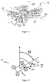
- the reference 10 generally denotes a drone, which is for example a quadrocopter such as the model Bebop Drone Parrot SA, Paris, France.
- This drone comprises a drone body 16 from which four connecting arms 18 radiate.
- Four coplanar rotor propulsion units 12 whose motors are controlled independently by an integrated navigation and attitude control system are respectively fixed on the four arm binding.
- the drone body 16 comprises an electronic card controlling the piloting of the drone.
- the drone comprises for example on the drone body, at least one obstacle sensor 14 secured directly or indirectly to the drone body, the main direction of detection is located in a substantially horizontal plane.
- At least one obstacle sensor is positioned on a face of the drone, in particular on a vertical face of the drone, so that the main direction of detection of said at least one obstacle sensor is located in a plane. substantially horizontal.
- at least one obstacle sensor is positioned at one end of a support integral with the drone body situated on one face of the drone, for example, on the upper face or the lower face of the drone, the position of said at least one obstacle sensor at the end of the support being such that the main direction of detection of said at least one obstacle sensor is located in a substantially horizontal plane.
- the drone comprises an obstacle sensor positioned on the front face of the drone body, the front face of the drone body being defined by the main direction of flight of said drone.
- the drone may comprise a camera capable of capturing a sequence of images positioned for example on the front part of the drone.
- the drone may further comprise a mobile support 28 mounted on the drone body comprising a camera 30 capable of capturing a sequence of images.
- the drone is equipped with inertial sensors (accelerometers and gyrometers) to measure with a certain accuracy the angular velocities and attitude angles of the drone, that is to say Euler angles (pitch, roll, and yaw) describing the inclination of the drone relative to a horizontal plane of a fixed land marker.
- inertial sensors accelerelerometers and gyrometers
- Euler angles pitch, roll, and yaw
- the drone 10 is controlled by a remote control device provided with a touch screen displaying a number of symbols for activating control commands by simply touching a user's finger. on the touch screen.
- the touch screen can also display the image captured by the camera of the drone 10, with overlay control symbols.
- the control device communicates with the drone 10 via a bidirectional exchange of data over wireless LAN type Wi-Fi (IEEE 802.11) or Bluetooth (registered trademarks): from the drone 10 to the control device, particularly for the transmission of data. the image captured by the camera, and the steering device to the drone 10 for sending pilot commands.
- Wi-Fi IEEE 802.11
- Bluetooth registered trademarks
- the drone transmits to the control device the images captured by the camera equipping the drone so that these images are displayed on the control device.
- the user of the drone can pilot the drone including from the received images and thus control the movement of the drone based on the received images.
- the drone keeps the camera oriented towards the target object to be filmed or, if the drone comprises a mobile camera support 28, the drone controls said mobile support 28 in order to maintain the aim from the camera in the direction of the target object determined to film.
- the drone comprises a flight mode for tracking a specific target object.
- the drone remotely tracks the target object and determines the position of the camera so that the camera can keep in focus the target object.
- the user of the drone may want to choose to follow the target object at the rear, front or on one side of the target object, front, back and side being defined with respect to the direction of movement of the target object.
- the camera is able to capture a sequence of images of a specific target seen from the drone.
- the drone may include means adapted to adapt the mobile support 28 of the camera so that the camera 30 captures images of said determined target.
- the drone must be able to avoid any obstacle, in order to avoid a fall of the drone that would be harmful.
- the attitude of the drone in flight will be corrected, in particular along the yaw axis to maintain the obstacle sensor 14 fixed directly or indirectly to the drone body in the direction direction of movement of the drone or if the drone comprises a plurality of obstacle sensors, maintain at least one obstacle sensor in the direction of movement of the drone. Maintaining at least one obstacle sensor in the direction of movement of the drone makes it possible to detect any obstacle in the flight environment in the flight direction of the drone and therefore incidentally to modify the trajectory of the drone to avoid if an obstacle was detected.
- the drone comprises a plurality of obstacle sensors, the obstacle sensor held in the direction movement of the drone detects any obstacle in the flight environment in the flight direction of the drone and other obstacle sensors detect lateral obstacles to the movement of the drone.
- the drone comprises means 40 for correcting the orientation of the drone capable of correcting yaw the orientation of the drone in flight so as to maintain the obstacle sensor 14 in the direction of movement of the drone.
- Said correction means are illustrated in figure 4 and will be detailed below.
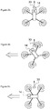
- FIGS. 2a, 2b and 2c illustrate the modification of the attitude of the drone when the drone must move either laterally on the left or rotate on the roll axis on the left.
- figure 2a illustrates the position of the drone before executing a lateral displacement or roll command
- the obstacle sensor located on the front face of the drone body is in the same direction as the sight of the camera illustrated by an arrow .
- the drone Upon receipt of a lateral movement command or rolling of the drone (represented by the double arrow pointing to the left on the Figures 2b and 2c ), the drone rotates along the yaw axis to orient the obstacle sensor positioned on the front face of the drone body in the direction of movement of the drone.
- the camera is then maintained for example according to its initial orientation so as to maintain the tracking for example of a specific object. So the figure 2b illustrates the yaw rotation movement of the drone until the front face of the drone body is oriented in the direction of movement of the drone as shown in FIG. Figure 2c .
- the aim of the camera being maintained on the target object, the user of the drone that will view the images captured by the camera will not undergo the rotational movements performed by the drone to orient the obstacle sensor in the direction of movement of the drone.
- This solution thus makes it possible to always orient the or an obstacle sensor in the direction of movement of the drone and thus allows an analysis of the flight environment of the drone, in particular in the direction of movement of the drone.
- the yaw correction of the drone performed by the correction means 40 firstly consists in determining, by determining means 42, an angular coordinate ⁇ of the drone. This is defined as the angle between the direction of movement of the drone ⁇ ref and the direction of the obstacle sensor ⁇ , the different directions being defined in the terrestrial reference established before the take-off of the drone at the time of setting under tension of the drone according to the conventional convention NED ("North, East, Down" in English terminology).
- the angular coordinate ⁇ of the drone is defined as the angle between the commanded direction of movement of the drone ⁇ refcmd , this commanded direction being determined from a received control command, and the direction of the obstacle sensor ⁇ , the directions being defined in the terrestrial reference.
- an angle determining the direction of movement of the drone ⁇ ref or the controlled direction of movement of the drone ⁇ refcmd is determined in the terrestrial reference according to the NED convention, for example with respect to the North in said reference, by means for detecting the direction of movement of the drone 44 and means for detecting the direction of the sensor obstacles 46, said detection means are, according to one embodiment, included in the means for determining an angular coordinate of the drone 42.
- an angle determining the direction of each obstacle sensor is determined.
- the means for detecting the direction of movement of the drone 44 and the direction of the obstacle sensor 46 or of each of the obstacle sensors are able to determine the angle determining the direction of movement of the drone. and the angle determining the direction of the obstacle sensor (s) in the terrestrial reference system (NED), for example with respect to North in said landmark.
- the angular coordinate ⁇ comprises the subtraction, performed by a subtraction means 48, of the angle determining the direction of movement of the drone ⁇ ref and the angle determining the direction of the obstacle sensor ⁇ .
- the angular coordinate ⁇ comprises the value of the smallest subtraction in absolute value of all the subtractions made by said subtraction means 48 of the angle determining the direction of movement of the drone ⁇ ref with respectively each angle determining the direction of an obstacle sensor.
- the drone further comprises means of corrective actions 50 able to control the drone in rotation along the yaw axis of said drone, the rotation being a function of the determined angular coordinate ⁇ , to align the direction of the obstacle sensor on the direction of movement of the drone.
- the integrated navigation and attitude control system of the drone will generate one or more differentiated commands from the determined angular coordinate ⁇ and will send them to one or more of the propulsion units 12 of the drone so as to produce the rotation of the drone.
- the sending of one or more differentiated commands comprises, for example, the generation of setpoint values of yaw angle and the application of these setpoint values to a servo control loop of the drone engines.
- the corrective action means 50 are able to control the drone in rotation along the yaw axis of said drone and to control the drone in rotation along the axis of pitch and / or roll.
- the drone comprises means 52 for reversing the orientation of the movable support 28 which are able to correct yaw the orientation of the mobile support 28 so as to maintain the camera in accordance with its direction before performing the corrective actions on said drone.
- the invention consists in correcting during the flight the aiming direction of one of said at least one obstacle sensor by a rotation of the drone so that the direction of sight of the obstacle sensor is always in the direction of displacement of the drone. It is important in this context, to correct the mobile support 28 of the camera so as not to reflect the correction performed on the drone on the mobile support but instead have a substantially opposite correction of the camera support so that the camera 30 maintains its aim for example on the target object to film.
- the means 52 for reversing the orientation of the drone comprise means of action on the movable support capable of controlling in rotation the movable support 28 according to the determined inverse angular coordinate (- ⁇ ) to maintain the direction of the camera 30 in its direction of sight, that is to say the direction prior to the corrective actions performed on said drone.
- the dynamic control method is illustrated in Figure 5 .
- the method comprises a step E1 for determining the trajectory of the drone.
- the trajectory is determined either according to commands received from the user or according to the movements of the target object to follow.
- Step E1 is followed by step E2 of determining the attitude angles of the drone to be modified in order to follow the determined trajectory and the generation of rotation angle setpoints of the drone according to the different angles of attitude. determined drone.
- Step E2 is followed by the step E3 of sending one or more differentiated commands determined according to the attitude angles determined at one or more of said thrusters 12 of the drone to control the attitude of said drone.
- the step E3 of sending one or more differentiated commands comprises, for example, the generation of angle setpoint values and the application of these setpoint values to a servo control loop of the drone motors.
- the step E1 is also followed by the step E4, which can be executed in parallel with the step E2, of determining the direction of movement of the drone from the determined trajectory. During this stage, it is determined the angle determining the direction of movement of the drone ⁇ ref in the terrestrial reference system (NED).
- NED terrestrial reference system
- Step E1 can also be followed by step E5, which can be executed in parallel with step E2 and / or step E4, for determining the direction of the obstacle sensor.
- step E5 the angle determining the direction of the obstacle sensor ⁇ in the terrestrial reference (NED) is determined.
- Steps E4 and E5 are followed by a step E6 of determining an angular coordinate ⁇ defined between the direction of movement of the drone and the direction of the obstacle sensor.
- the angular coordinate ⁇ is determined by subtraction at the angle determining the direction of movement of the drone ⁇ ref , the angle determining the direction of the obstacle sensor ⁇ .
- Step E6 is followed by a step E7 of sending differentiated commands determined as a function of the angular coordinate ⁇ determined at one or more of said thrusters 12 of the drone to modify the rotation along the yaw axis of said drone and therefore allow rotation of the drone so as to maintain the obstacle sensor in the direction of movement of the drone.
- the step E7 of sending one or more differentiated commands comprises, for example, the generation of setpoint values of yaw angle and the application of these setpoint values to a control servo control loop of the drone engines.
- the method also comprises a step E8 which follows the step E6 sending correction commands in reverse to that of the drone to said mobile support 28 so as not to rotate the image targeted by the camera 30.
- the drone performs a yaw rotation of a determined angle ⁇ and the support mobile must rotate in opposite direction that is to say - ⁇ to maintain the camera in its direction of sighting.
- the commands for correcting the yaw rotation of the drone and the reverse correction control of the yaw rotation of the movable support must be performed synchronously in order to keep the camera in its aiming direction, in particular in order to avoid any unintentional movement. desired in the succession of images forming the film of the target.
- said method realizes a correction of the direction of the drone as soon as a piloting command is received, and on the basis of the information contained in said piloting command (and not from the determined trajectory of the drone), namely the attitude change information, in particular indicating rotation on the roll axis or controlled lateral displacement.
- Said method comprises a step E11 for receiving a control command for modifying the attitude of the drone.
- Step E11 is followed by step E12 for determining the controlled direction angle of movement of the drone, this controlled direction being determined from the received piloting command. During this step, it determines the angle determining the direction of movement of the drone ⁇ refcmd in the terrestrial reference system (NED).
- NED terrestrial reference system
- Step E11 may also be followed by step E13, which may be executed in parallel with step E12, for determining the direction of the obstacle sensor.
- step E13 the angle determining the direction of the obstacle sensor ⁇ in the terrestrial reference (NED) is determined.
- Steps E12 and E13 are followed by a step E14 of determining an angular coordinate ⁇ defined between the controlled direction of movement of the drone and the direction of the obstacle sensor.
- the angular coordinate ⁇ is determined by the subtraction at the angle determining the direction of movement of the drone ⁇ refcmd , the angle determining the direction of the obstacle sensor ⁇ .
- Step E14 is followed by a step E15 of sending differentiated commands determined according to the angular coordinate ⁇ determined at one or more of said propulsion units 12 of the drone to modify the rotation. according to the yaw axis of said drone and thus allow rotation of the drone so as to maintain the obstacle sensor in the direction of movement of the drone.
- the step E15 of sending one or more differentiated commands comprises, for example, the generation of setpoint values of yaw angle and the application of these setpoint values to a servo control loop of the drone engines.
- the method further comprises a step E16 which follows the step E14 of sending correction commands in reverse to that of the drone to said mobile support 28 so as not to rotate the image targeted by the camera 30.
- the drone performs a yaw rotation of a determined angle ⁇ and the support mobile must rotate in opposite direction that is to say - ⁇ to maintain the camera in its direction of sighting.
- the commands for correcting the yaw rotation of the drone and the reverse correction control of the yaw rotation of the movable support must be performed synchronously in order to keep the camera in its aiming direction, in particular in order to avoid any unintentional movement. desired in the succession of images forming the film of the target.
Abstract
L'invention concerne un drone à voilure tournante (10) comprenant un corps de drone (16) comprenant une carte électronique contrôlant le pilotage du drone et une pluralité de bras de liaison, une pluralité de blocs propulseurs (12) montés sur des bras de liaison (18) respectifs, au moins un capteur d'obstacles (14) solidaire du corps de drone, dont la direction principale de détection est située dans un plan sensiblement horizontal. Le drone comprend des moyens de correction (40) de l'orientation du drone aptes à corriger en lacet l'orientation du drone en vol de sorte à maintenir un dudit au moins un capteur d'obstacles dans la direction de déplacement du drone.

Description
L'invention concerne les engins volants motorisés tels que les drones, notamment les drones à voilure tournante de type quadricoptère.The invention relates to powered flying machines such as drones, including quadrocopter type rotary wing drones.
L'AR.Drone 2.0 ou le Bebop Drone de Parrot SA, Paris, France sont des exemples typiques de tels quadricoptères. Ils sont équipés d'une série de capteurs (accéléromètres, gyromètres 3 axes, altimètre) comprennent un bloc caméra. Ces drones sont pourvus de plusieurs rotors entrainés par des moteurs respectifs aptes à être commandés de manière différenciée afin de piloter le drone en attitude et en vitesse. Ces drones peuvent comprendre au moins un bloc caméra vidéo captant une image de la scène vers laquelle est dirigé le drone. The AR.Drone 2.0 or the Bebop Drone of Parrot SA, Paris, France are typical examples of such quadricopters. They are equipped with a series of sensors (accelerometers, 3-axis gyrometers, altimeter) include a camera block. These drones are provided with several rotors driven by respective engines able to be controlled in a differentiated manner to control the drone attitude and speed. These drones may include at least one video camera block capturing an image of the scene to which the drone is directed.
Il est connu des drones équipés d'un système détecteur d'obstacles et d'évitement autonome des obstacles. Pour ce faire, le système de détection et l'évitement d'obstacles est composé de deux capteurs optiques positionnés sur la face avant du drone, la face avant étant définie par la face de direction normale de déplacement vers l'avant du drone. En outre, le drone comprend un logiciel d'analyse d'images en vue de détecter des obstacles et qui immobilise le drone s'il apparait que le passage est bloqué. Si l'obstacle peut être contourné, alors le drone choisit un nouveau chemin.It is known drones equipped with an obstacle detection system and autonomous obstacle avoidance. To do this, the detection system and the obstacle avoidance is composed of two optical sensors positioned on the front face of the drone, the front face being defined by the normal direction face of movement towards the front of the drone. In addition, the drone includes an image analysis software for detecting obstacles and immobilizing the drone if it appears that the passage is blocked. If the obstacle can be bypassed, then the drone chooses a new path.
Toutefois, ce drone est uniquement capable de détecter et éviter un obstacle situé devant la face avant du drone. En effet, si l'obstacle est de biais, le système ne permet pas une bonne détection de l'objet. Il en est de même concernant les obstacles situés au-dessus ou en dessous du drone, ces obstacles ne seront pas détectés.However, this drone is only able to detect and avoid an obstacle located in front of the front face of the drone. Indeed, if the obstacle is biased, the system does not allow a good detection of the object. The same applies to obstacles located above or below the drone, these obstacles will not be detected.
Ces drones peuvent être en particulier pilotés par un utilisateur via un dispositif de pilotage. En outre, il est connu des drones ayant un mode de fonctionnement autonome de sorte que le drone est apte à suivre un objet cible à filmer. Le drone suivant l'objet cible ajuste sa position et/ou la position du bloc caméra afin que l'objet cible soit toujours filmé par le drone. Le drone étant autonome, c'est-à-dire le déplacement est calculé par le drone et non piloté par un utilisateur, il détermine sa trajectoire en fonction des mouvements de l'objet cible et commande le bloc caméra afin que celui-ci soit toujours en direction de l'objet cible à filmer.These drones can be driven in particular by a user via a control device. In addition, it is known drones having an autonomous mode of operation so that the drone is able to follow a target object to be filmed. The drone following the target object adjusts its position and / or the position of the camera block so that the target object is always filmed by the drone. The drone being autonomous, that is to say the displacement is calculated by the drone and not driven by a user, it determines its trajectory according to the movements of the target object and controls the camera block so that it is always in the direction of the target object to be filmed.
Le système détecteur d'obstacles étant positionné sur la face avant du drone, celui-ci ne peut donc détecter que les obstacles situés dans le champ de vision des capteurs optiques, c'est-à-dire les obstacles situés à l'avant du drone. Ainsi, dans le cas de la mise en oeuvre du suivi d'un objet cible, le drone est contraint de suivre l'objet cible en restant derrière cet objet afin de permettre une analyse des images frontales du drone. Cette solution limite donc le mode de suivi et de capture d'une vidéo de l'objet cible. En effet, les mouvements latéraux et de recul du drone ne permettent pas l'évitement d'obstacles.Since the obstacle detection system is positioned on the front face of the drone, it can only detect obstacles located in the field of vision of the optical sensors, that is to say the obstacles located at the front of the drone. Thus, in the case of implementing the tracking of a target object, the drone is constrained to follow the target object while remaining behind this object to allow an analysis of the frontal images of the drone. This solution therefore limits the mode of tracking and capturing a video of the target object. Indeed, the lateral movements and recoil of the drone do not allow the avoidance of obstacles.
Une solution permettant de résoudre ce problème consiste à équiper le drone d'une pluralité de systèmes de détection et l'évitement d'obstacles autour du corps du drone afin de permettre une analyse pour l'évitement d'obstacles tout autour du drone. Une telle solution permet un déplacement du drone latéralement et un mouvement de recul du drone. Toutefois, cette solution présente l'inconvénient d'être très onéreuse puisqu'elle nécessite la présence d'une multitude de systèmes de détection et l'évitement d'obstacles de sorte à analyser l'environnement de vol du drone tout autour du drone.A solution to this problem is to equip the drone with a plurality of detection systems and obstacle avoidance around the body of the drone to allow an analysis for the avoidance of obstacles around the drone. Such a solution allows movement of the drone laterally and recoil motion of the drone. However, this solution has the disadvantage of being very expensive since it requires the presence of a multitude of detection systems and obstacle avoidance so as to analyze the flying environment of the drone around the drone.
Le but de l'invention est de remédier à ces divers inconvénients, en proposant un drone muni d'au moins un capteur d'obstacles solidaire du corps de drone, ledit au moins un capteur d'obstacles ayant une direction principale de détection située dans un plan sensiblement horizontal et de moyens spécifiques corrigeant l'attitude du drone de sorte que le capteur d'obstacles puisse toujours analyser l'environnement de vol dans la direction de déplacement du drone et donc éviter les obstacles lors du déplacement du drone. De plus, un tel mode de réalisation permet d'optimiser le nombre de capteurs d'obstacles sur le drone et incidemment le coût du drone.The object of the invention is to overcome these various disadvantages, by proposing a drone provided with at least one obstacle sensor secured to the drone body, said at least one obstacle sensor having a main direction of detection located in a substantially horizontal plane and specific means correcting the attitude of the drone so that the obstacle sensor can always analyze the flight environment in the direction of movement of the drone and therefore avoid obstacles when moving the drone. In addition, such an embodiment makes it possible to optimize the number of obstacle sensors on the drone and, incidentally, the cost of the drone.
A cet effet, l'invention propose un drone à voilure tournante comprenant un corps de drone comprenant une carte électronique contrôlant le pilotage du drone et une pluralité de bras de liaison, une pluralité de blocs propulseurs montés sur des bras de liaison respectifs, au moins un capteur d'obstacles solidaire du corps de drone dont la direction principale de détection est située dans un plan sensiblement horizontal.For this purpose, the invention proposes a rotary wing drone comprising a drone body comprising an electronic card controlling the steering of the drone and a plurality of connecting arms, a plurality of propulsion units mounted on respective link arms, at least an obstacle sensor integral with the drone body whose main direction of detection is located in a substantially horizontal plane.
De façon caractéristique, le drone comprend des moyens de correction de l'orientation du drone aptes à corriger en lacet l'orientation du drone en vol de sorte à maintenir un dudit au moins un capteur d'obstacles dans la direction de déplacement du drone.In a characteristic manner, the drone comprises means for correcting the orientation of the drone capable of correcting the orientation of the drone flight so as to maintain one of said at least one obstacle sensor in the direction of movement of the drone.
Selon diverses caractéristiques subsidiaires, prises ensemble ou isolément :
- les moyens de correction de l'orientation du drone comprennent :
- ∘ des moyens de détermination d'une coordonnée angulaire définie entre une direction de déplacement du drone et une direction du capteur d'obstacles et
- ∘ des moyens d'actions correctrices aptes à commander en rotation le drone selon l'axe de lacet dudit drone, la rotation étant fonction de la coordonnée angulaire déterminée, permettant d'aligner la direction du capteur d'obstacles sur la direction de déplacement du drone.
- les moyens d'actions correctrices comprennent en outre des moyens aptes à agir en rotation selon l'axe de roulis et/ou selon l'axe de tangage afin de maintenir la direction du capteur d'obstacles dans la direction de déplacement du drone.
- les moyens de détermination d'une coordonnée angulaire comprennent des moyens de détection de la direction de déplacement du drone et des moyens de détection de la direction du capteur d'obstacles.
- les moyens de détection de la direction de déplacement du drone sont aptes à déterminer l'angle déterminant la direction de déplacement du drone ψref dans le repère terrestre (NED) ou l'angle déterminant une direction commandée de déplacement du drone ψrefcmd dans le repère terrestre (NED), ladite direction commandée étant déterminée à partir d'une commande de pilotage reçue par le drone.
- les moyens de détection de la direction du capteur d'obstacles sont aptes à déterminer l'angle déterminant la direction du capteur d'obstacles ψ dans le repère terrestre (NED).
- les moyens de détermination de ladite coordonnée angulaire comprennent un moyen de soustraction de l'angle déterminant le déplacement du drone ou l'angle déterminant la direction commandée de déplacement du drone et de l'angle déterminant la direction du capteur d'obstacles.
- le drone comprend en outre un support mobile monté sur le corps de drone comprenant une caméra apte à capter une séquence d'images et des moyens de correction inverse de l'orientation du support mobile aptes à corriger en lacet l'orientation du support de sorte à maintenir la caméra dans sa direction de visée .
- les moyens de correction inverse de l'orientation du drone comprennent des moyens d'actions sur le support mobile aptes à commander en rotation le support mobile selon la coordonnée angulaire inverse déterminée permettant de maintenir la direction de la caméra dans sa direction de visée.
- the means for correcting the orientation of the drone comprise:
- Means for determining an angular coordinate defined between a direction of movement of the drone and a direction of the obstacle sensor and
- ∘ corrective action means adapted to control the drone in rotation along the yaw axis of said drone, the rotation being a function of the determined angular coordinate, making it possible to align the direction of the obstacle sensor with the direction of movement of the drone; drone.
- the corrective action means further comprise means able to act in rotation along the roll axis and / or along the pitch axis in order to maintain the direction of the obstacle sensor in the direction of movement of the drone.
- the means for determining an angular coordinate comprise means for detecting the direction of movement of the drone and means for detecting the direction of the obstacle sensor.
- the detection means of the direction of movement of the drone are able to determine the angle determining the direction of movement of the drone ψ ref in the terrestrial reference system (NED) or the angle determining a controlled direction of movement of the drone ψ refcmd in the terrestrial landmark (NED), said commanded direction being determined from a piloting command received by the drone.
- the means for detecting the direction of the obstacle sensor are able to determine the angle determining the direction of the obstacle sensor ψ in the terrestrial reference system (NED).
- the means for determining said angular coordinate comprise means for subtracting the angle determining the displacement of the drone or the angle determining the controlled direction the movement of the drone and the angle determining the direction of the obstacle sensor.
- the drone further comprises a mobile support mounted on the drone body comprising a camera capable of capturing a sequence of images and means for reversely correcting the orientation of the mobile support able to correct yaw the orientation of the medium so that to hold the camera in its aiming direction.
- the means for reversing the orientation of the drone comprise means for actions on the movable support able to rotate the mobile support in the determined inverse angular coordinate to maintain the direction of the camera in its direction of view.
L'invention concerne également un procédé de contrôle dynamique d'attitude d'un drone à voilure tournante comprenant un corps de drone, une pluralité de bras de liaison, une pluralité de blocs propulseurs montés sur des bras de liaison respectifs et au moins un capteur d'obstacles solidaire du corps de drone dont la direction principale de détection est située dans un plan sensiblement horizontal.The invention also relates to a dynamic attitude control method of a rotary wing drone comprising a drone body, a plurality of link arms, a plurality of propulsion units mounted on respective link arms and at least one sensor. of obstacles integral with the drone body whose main direction of detection is located in a substantially horizontal plane.
De façon caractéristique, lorsque le drone vole, l'attitude du drone est contrôlée par l'envoi de commandes de correction de l'orientation du drone à un ou plusieurs desdits blocs propulseurs pour corriger en lacet l'orientation du drone en vol de sorte à maintenir un dudit au moins un capteur d'obstacles dans la direction de déplacement du drone.Typically, when the drone flies, the attitude of the drone is controlled by sending commands for correcting the orientation of the drone to one or more of said propulsion units to correct the orientation of the drone in flight so that maintaining one of said at least one obstacle sensor in the direction of movement of the drone.
Selon un mode de réalisation particulier, le procédé comprend :
- une étape de détermination d'une coordonnée angulaire définie entre une direction de déplacement du drone et une direction du capteur d'obstacles et
- une étape d'envoi de commande en rotation du drone selon l'axe de lacet dudit drone, la rotation étant fonction de la coordonnée angulaire déterminée, permettant d'aligner la direction du capteur d'obstacles sur la direction de déplacement du drone.
- a step of determining an angular coordinate defined between a direction of movement of the drone and a direction of the obstacle sensor and
- a command sending step in rotation of the drone along the yaw axis of said drone, the rotation being a function of the determined angular coordinate, to align the direction of the obstacle sensor on the direction of movement of the drone.
Selon un autre mode de réalisation, le procédé comprend en outre une étape de détection de la direction de déplacement du drone et une étape de détection de la direction du capteur d'obstacles.According to another embodiment, the method further comprises a step of detecting the direction of movement of the drone and a step of detecting the direction of the obstacle sensor.
Selon encore un autre mode de réalisation, ladite coordonnée angulaire est obtenue à partir de la direction de déplacement du drone et de la direction du capteur d'obstacles.According to yet another embodiment, said angular coordinate is obtained from the direction of movement of the drone and the direction of the obstacle sensor.
Selon un mode de réalisation particulier, le drone comprend en outre un support mobile monté sur le corps de drone comprenant une caméra apte à capter une séquence d'images depuis le drone et le procédé comprend en outre une étape de correction inverse de l'orientation du support mobile pour corriger en lacet l'orientation du support de sorte à maintenir la caméra dans sa direction de visée.According to a particular embodiment, the drone further comprises a mobile support mounted on the drone body comprising a camera capable of capturing a sequence of images from the drone and the method further comprises a reverse correction step of the orientation. mobile support for yawing the orientation of the support so as to maintain the camera in its aiming direction.
On va maintenant décrire un exemple de mise en oeuvre de la présente invention, en référence aux dessins annexés où les mêmes références désignent d'une figure à l'autre des éléments identiques ou fonctionnellement semblables.
- La
Figure 1 est une vue d'ensemble montrant le drone conformément à l'invention. - Les
Figures 2a, 2b et 2c sont des vues illustrant la correction de l'orientation du drone selon l'invention. - La
Figure 3 est un schéma illustrant la détermination d'une coordonnée angulaire. - La
Figure 4 une vue détaillée des moyens de correction de l'orientation du drone conformément à l'invention. - La
Figure 5 illustre un organigramme de correction de l'orientation du drone conformément à l'invention - La
Figure 6 illustre un autre organigramme de correction de l'orientation du drone conformément à l'invention.
- The
Figure 1 is an overview showing the drone according to the invention. - The
Figures 2a, 2b and 2c are views illustrating the correction of the orientation of the drone according to the invention. - The
Figure 3 is a diagram illustrating the determination of an angular coordinate. - The
Figure 4 a detailed view of the means for correcting the orientation of the drone according to the invention. - The
Figure 5 illustrates a flow chart for correcting the orientation of the drone in accordance with the invention - The
Figure 6 illustrates another flow chart for correcting the orientation of the drone according to the invention.
On va maintenant décrire un exemple de réalisation et de mise en oeuvre de l'invention.An example embodiment and implementation of the invention will now be described.
Sur la
Le corps de drone 16 comprend une carte électronique contrôlant le pilotage du drone.The
Conformément à l'invention, le drone comprend par exemple sur le corps de drone, au moins un capteur d'obstacles 14 solidaire directement ou indirectement du corps de drone, dont la direction principale de détection est située dans un plan sensiblement horizontal.According to the invention, the drone comprises for example on the drone body, at least one
Selon un mode de réalisation particulier, au moins un capteur d'obstacles est positionné sur une face du drone notamment sur une face verticale du drone, de sorte que la direction principale de détection dudit au moins un capteur d'obstacles est située dans un plan sensiblement horizontal. Selon un autre mode de réalisation particulier, au moins un capteur d'obstacles est positionné à une extrémité d'un support solidaire du corps de drone situé sur une face du drone, par exemple, sur la face supérieure ou la face inférieure du drone, la position dudit au moins un capteur d'obstacles à l'extrémité du support étant telle que la direction principale de détection dudit au moins un capteur d'obstacles est située dans un plan sensiblement horizontal.According to a particular embodiment, at least one obstacle sensor is positioned on a face of the drone, in particular on a vertical face of the drone, so that the main direction of detection of said at least one obstacle sensor is located in a plane. substantially horizontal. According to another particular embodiment, at least one obstacle sensor is positioned at one end of a support integral with the drone body situated on one face of the drone, for example, on the upper face or the lower face of the drone, the position of said at least one obstacle sensor at the end of the support being such that the main direction of detection of said at least one obstacle sensor is located in a substantially horizontal plane.
Selon un mode de réalisation particulier et illustré en
Selon un mode de réalisation, le drone peut comprendre une caméra apte à capter une séquence d'images positionnée par exemple sur la partie avant du drone.According to one embodiment, the drone may comprise a camera capable of capturing a sequence of images positioned for example on the front part of the drone.
Selon un autre mode de réalisation, le drone peut comprendre en outre un support mobile 28 monté sur le corps de drone comprenant une caméra 30 apte à capter une séquence d'images.According to another embodiment, the drone may further comprise a
Selon un exemple de réalisation, le drone est muni de capteurs inertiels (accéléromètres et gyromètres) permettent de mesurer avec une certaine précision les vitesses angulaires et les angles d'attitude du drone, c'est-à-dire les angles d'Euler (tangage, roulis et lacet) décrivant l'inclinaison du drone par rapport à un plan horizontal d'un repère terrestre fixe.According to an exemplary embodiment, the drone is equipped with inertial sensors (accelerometers and gyrometers) to measure with a certain accuracy the angular velocities and attitude angles of the drone, that is to say Euler angles (pitch, roll, and yaw) describing the inclination of the drone relative to a horizontal plane of a fixed land marker.
Selon un mode de réalisation de l'invention, le drone 10 est piloté par un dispositif de pilotage distant pourvu d'un écran tactile affichant un certain nombre de symboles permettant l'activation de commandes de pilotage par simple contact du doigt d'un utilisateur sur l'écran tactile.According to one embodiment of the invention, the
L'écran tactile peut également afficher l'image captée par la caméra du drone 10, avec en superposition les symboles de commande.The touch screen can also display the image captured by the camera of the
Le dispositif de pilotage communique avec le drone 10 via un échange bidirectionnel de données par liaison sans fil de type réseau local Wi-Fi (IEEE 802.11) ou Bluetooth (marques déposées) : du drone 10 vers le dispositif de pilotage notamment pour la transmission de l'image captée par la caméra, et du dispositif de pilotage vers le drone 10 pour l'envoi de commandes de pilotage.The control device communicates with the
Le pilotage du drone 10 consiste à faire évoluer celui-ci par :
- a) rotation autour d'un axe de tangage 22, pour le faire avance ou reculer ; et/ou
- b) rotation autour d'un axe de roulis 24, pour le déplacer vers la droite ou vers la gauche ; et/ou
- c) rotation autour d'un axe de cap, ou axe de lacet 26, pour faire pivoter vers la droite ou vers la gauche l'axe principal du drone, donc la direction de pointage de la face avant du drone ; et/ou
- d) translation vers le bas ou vers le haut par changement du régime des gaz, de manière à respectivement réduire ou augmenter l'altitude du drone.
- a) rotation about a
pitch axis 22, to advance or retreat; and or - b) rotation about a
roll axis 24, to move it to the right or to the left; and or - c) rotation about a heading axis, or
yaw axis 26, to rotate to the right or to the left the main axis of the drone, therefore the pointing direction of the front face of the drone; and or - d) translation downwards or upwards by changing the speed of the gasses so as to respectively reduce or increase the altitude of the drone.
Selon un mode de réalisation particulier, le drone transmet au dispositif de pilotage les images captées par la caméra équipant le drone de sorte que ces images sont affichées sur le dispositif de pilotage. Ainsi, l'utilisateur du drone peut piloter le drone notamment à partir des images reçues et donc commander le déplacement du drone en se basant sur les images reçues.According to a particular embodiment, the drone transmits to the control device the images captured by the camera equipping the drone so that these images are displayed on the control device. Thus, the user of the drone can pilot the drone including from the received images and thus control the movement of the drone based on the received images.
Selon un autre mode de réalisation, il est possible d'indiquer au drone un objet cible déterminé devant être filmé par la caméra embarquée dans le drone.According to another embodiment, it is possible to indicate to the drone a determined target object to be filmed by the camera embedded in the drone.
Ainsi, durant le pilotage du drone par l'utilisateur, le drone maintient la caméra orientée vers l'objet cible à filmer ou, si le drone comprend un support mobile de caméra 28, le drone commande ledit support mobile 28 afin de maintenir la visée de la caméra dans la direction de l'objet cible déterminé à filmer.Thus, during piloting of the drone by the user, the drone keeps the camera oriented towards the target object to be filmed or, if the drone comprises a
Selon un autre mode de réalisation complémentaire ou alternatif au mode de réalisation précédent, le drone comprend un mode de vol permettant un suivi d'un objet cible déterminé. Selon ce mode de réalisation, le drone suit à distance l'objet cible et détermine la position de la caméra afin que celle-ci puisse maintenir en visée l'objet cible. Dans ce mode de réalisation particulier, l'utilisateur du drone peut vouloir choisir de suivre l'objet cible à l'arrière, à l'avant ou sur un côté de l'objet cible, l'avant, l'arrière et le côté étant défini par rapport à la direction de déplacement de l'objet cible.According to another embodiment complementary or alternative to the previous embodiment, the drone comprises a flight mode for tracking a specific target object. According to this embodiment, the drone remotely tracks the target object and determines the position of the camera so that the camera can keep in focus the target object. In this particular embodiment, the user of the drone may want to choose to follow the target object at the rear, front or on one side of the target object, front, back and side being defined with respect to the direction of movement of the target object.
Au sein de ces différents modes de réalisation, la caméra est apte à capter une séquence d'images d'une cible déterminée vue depuis le drone. Pour ce faire, le drone peut comprendre des moyens aptes à adapter le support mobile 28 de la caméra de sorte que la caméra 30 capte des images de ladite cible déterminée.Within these different embodiments, the camera is able to capture a sequence of images of a specific target seen from the drone. To do this, the drone may include means adapted to adapt the
Dans ces différents modes de réalisation, le drone doit être capable d'éviter tout obstacle, afin d'éviter une chute du drone qui lui serait dommageable.In these different embodiments, the drone must be able to avoid any obstacle, in order to avoid a fall of the drone that would be harmful.
Pour ce faire et conformément à l'invention, l'attitude du drone en vol va être corrigée, en particulier selon l'axe de lacet afin de maintenir le capteur d'obstacles 14 fixé directement ou indirectement sur le corps de drone dans le sens de direction de déplacement du drone ou si le drone comprend une pluralité de capteurs d'obstacles, maintenir au moins un capteur d'obstacles dans le sens de direction de déplacement du drone. Le fait de maintenir au moins un capteur d'obstacles dans la direction de déplacement du drone permet de détecter tout obstacle se trouvant dans l'environnement de vol dans la direction de vol du drone et donc incidemment de modifier la trajectoire du drone pour éviter si un obstacle venait à être détecté.To do this and according to the invention, the attitude of the drone in flight will be corrected, in particular along the yaw axis to maintain the
Selon un mode de réalisation particulier, le drone comprend une pluralité de capteurs d'obstacles, le capteur d'obstacles maintenu dans la direction de déplacement du drone détecte tout obstacle se trouvant dans l'environnement de vol dans la direction de vol du drone et les autres capteurs d'obstacles permettent de détecter les obstacles latéraux par rapport au déplacement du drone.According to a particular embodiment, the drone comprises a plurality of obstacle sensors, the obstacle sensor held in the direction movement of the drone detects any obstacle in the flight environment in the flight direction of the drone and other obstacle sensors detect lateral obstacles to the movement of the drone.
Pour cela, le drone comprend des moyens de correction 40 de l'orientation du drone aptes à corriger en lacet l'orientation du drone en vol de sorte à maintenir le capteur d'obstacles 14 dans la direction de déplacement du drone. Lesdits moyens de correction sont illustrés en
Les
En particulier, la
Dès réception d'une commande de déplacement latéral ou de roulis du drone (représentée par la double flèche dirigée vers la gauche sur les
Cette solution permet ainsi de toujours orienter le ou un capteur d'obstacles dans la direction de déplacement du drone et donc permet une analyse de l'environnement de vol du drone en particulier dans la direction de déplacement du drone.This solution thus makes it possible to always orient the or an obstacle sensor in the direction of movement of the drone and thus allows an analysis of the flight environment of the drone, in particular in the direction of movement of the drone.
Tel qu'illustré en
Selon un mode de réalisation particulier, la coordonnée angulaire ϕ du drone est définie comme étant l'angle entre la direction commandée de déplacement du drone ψrefcmd, cette direction commandée étant déterminée à partir d'une commande de pilotage reçue, et la direction du capteur d'obstacles ψ, les directions étant définies dans le repère terrestre. Conformément à l'invention, un angle déterminant la direction de déplacement du drone ψref ou la direction commandée de déplacement du drone ψrefcmd, cette direction commandée étant déterminée à partir d'une commande de pilotage reçue, et un angle déterminant la direction du capteur d'obstacles ψ sont déterminées dans le repère terrestre selon la convention NED, par exemple par rapport au Nord dans ledit repère, par des moyens de détection de la direction de déplacement du drone 44 et des moyens de détection de la direction du capteur d'obstacles 46, lesdits moyens de détection sont, selon un mode de réalisation, compris dans les moyens de détermination d'une coordonnée angulaire du drone 42. Selon un mode de réalisation particulier d'un drone comprenant une pluralité de capteurs d'obstacles, un angle déterminant la direction de chaque capteur d'obstacles est déterminé.According to a particular embodiment, the angular coordinate φ of the drone is defined as the angle between the commanded direction of movement of the drone ψ refcmd , this commanded direction being determined from a received control command, and the direction of the obstacle sensor ψ, the directions being defined in the terrestrial reference. In accordance with the invention, an angle determining the direction of movement of the drone ψ ref or the controlled direction of movement of the drone ψ refcmd , this controlled direction being determined from a received control command, and an angle determining the direction of the obstacle sensor ψ are determined in the terrestrial reference according to the NED convention, for example with respect to the North in said reference, by means for detecting the direction of movement of the
Selon un mode de réalisation, les moyens de détection de la direction de déplacement du drone 44 et de la direction du capteur d'obstacles 46 ou de chacun des capteurs d'obstacles sont aptes à déterminer l'angle déterminant la direction de déplacement du drone et l'angle déterminant la direction du ou des capteur(s) d'obstacles dans le repère terrestre (NED), par exemple par rapport au Nord dans ledit repère.According to one embodiment, the means for detecting the direction of movement of the
Selon un mode de réalisation particulier, la coordonnée angulaire ϕ comprend la soustraction, réalisée par un moyen de soustraction 48, de l'angle déterminant la direction de déplacement du drone ψref et de l'angle déterminant la direction du capteur d'obstacles ψ.According to a particular embodiment, the angular coordinate φ comprises the subtraction, performed by a subtraction means 48, of the angle determining the direction of movement of the drone ψ ref and the angle determining the direction of the obstacle sensor ψ.
Selon le mode de réalisation dans lequel le drone comprend une pluralité de capteurs d'obstacles, la coordonnée angulaire ϕ comprend la valeur de la soustraction la plus petite en valeur absolue de l'ensemble des soustractions réalisées par ledit moyen de soustraction 48 de l'angle déterminant la direction de déplacement du drone ψref avec respectivement chaque angle déterminant la direction d'un capteur d'obstacles.According to the embodiment in which the drone comprises a plurality of obstacle sensors, the angular coordinate φ comprises the value of the smallest subtraction in absolute value of all the subtractions made by said subtraction means 48 of the angle determining the direction of movement of the drone ψ ref with respectively each angle determining the direction of an obstacle sensor.
Le drone comprend en outre des moyens d'actions correctrices 50 aptes à commander en rotation le drone selon l'axe de lacet dudit drone, la rotation étant fonction de la coordonnée angulaire ϕ déterminée, permettant d'aligner la direction du capteur d'obstacles sur la direction de déplacement du drone.The drone further comprises means of
Pour ce faire, le système intégré de navigation et de contrôle d'attitude du drone va générer une ou des commandes différenciées à partir de la coordonnée angulaire ϕ déterminée et va les envoyer à un ou plusieurs des blocs propulseurs 12 du drone de manière à produire la rotation du drone.To do this, the integrated navigation and attitude control system of the drone will generate one or more differentiated commands from the determined angular coordinate φ and will send them to one or more of the
L'envoi d'une ou plusieurs commandes différenciées comprend par exemple la génération de valeurs de consigne d'angle en lacet et l'application de ces valeurs de consigne à une boucle d'asservissement de contrôle des moteurs du drone.The sending of one or more differentiated commands comprises, for example, the generation of setpoint values of yaw angle and the application of these setpoint values to a servo control loop of the drone engines.
Selon un mode de réalisation particulier, les moyens d'actions correctrices 50 sont aptes à commander en rotation le drone selon l'axe de lacet dudit drone et à commander en rotation le drone selon l'axe de tangage et/ou de roulis.According to a particular embodiment, the corrective action means 50 are able to control the drone in rotation along the yaw axis of said drone and to control the drone in rotation along the axis of pitch and / or roll.
En outre, selon un mode de réalisation particulier, le drone comprend des moyens de correction inverse 52 de l'orientation du support mobile 28 qui sont aptes à corriger en lacet l'orientation du support mobile 28 de sorte à maintenir la caméra conformément à sa direction avant d'effectuer les actions correctrices sur ledit drone.In addition, according to a particular embodiment, the drone comprises means 52 for reversing the orientation of the
En effet, l'invention consiste à corriger durant le vol la direction de visée d'un dudit au moins un capteur d'obstacles par une rotation du drone afin que la direction de visée du capteur d'obstacles soit toujours dans la direction de déplacement du drone. Il est important dans ce contexte, de corriger le support mobile 28 de la caméra afin de ne pas répercuter la correction opérée sur le drone sur le support mobile mais au contraire avoir une correction sensiblement inverse du support de camera afin que la caméra 30 maintienne sa visée par exemple sur l'objet cible à filmer. Pour ce faire, les moyens de correction inverse 52 de l'orientation du drone comprennent des moyens d'actions sur le support mobile aptes à commander en rotation le support mobile 28 selon la coordonnée angulaire inverse (-ϕ) déterminée permettant de maintenir la direction de la caméra 30 dans sa direction de visée c'est-à-dire la direction préalable aux actions correctrices effectuées sur ledit drone.Indeed, the invention consists in correcting during the flight the aiming direction of one of said at least one obstacle sensor by a rotation of the drone so that the direction of sight of the obstacle sensor is always in the direction of displacement of the drone. It is important in this context, to correct the
Il va être maintenant décrit les différentes étapes du procédé mis en oeuvre dans le drone afin de contrôler dynamiquement l'attitude du drone et en particulier déterminer les commandes différenciées à envoyer à un ou plusieurs blocs propulseurs 12 du drone afin de maintenir le capteur d'obstacles dudit drone dans la direction de déplacement du drone.The various steps of the method implemented in the drone will now be described in order to dynamically control the attitude of the drone and in particular to determine the differentiated commands to be sent to one or
Le procédé de contrôle dynamique est illustré en
Le procédé comprend une étape E1 de détermination de la trajectoire du drone. Selon le mode de navigation du drone, la trajectoire est déterminée soit en fonction des commandes reçues de l'utilisateur soit en fonction des mouvements de l'objet cible à suivre.The method comprises a step E1 for determining the trajectory of the drone. Depending on the navigation mode of the drone, the trajectory is determined either according to commands received from the user or according to the movements of the target object to follow.
L'étape E1 est suivie de l'étape E2 de détermination des angles d'attitude du drone à modifier afin de suivre la trajectoire déterminée et de la génération de valeurs de consigne d'angle de rotation du drone selon les différents angles d'attitude du drone déterminés.Step E1 is followed by step E2 of determining the attitude angles of the drone to be modified in order to follow the determined trajectory and the generation of rotation angle setpoints of the drone according to the different angles of attitude. determined drone.
L'étape E2 est suivie de l'étape E3 d'envoi d'une ou plusieurs commandes différenciées déterminées en fonction des angles d'attitudes déterminés à un ou plusieurs desdits blocs propulseurs 12 du drone pour contrôler l'attitude dudit drone.Step E2 is followed by the step E3 of sending one or more differentiated commands determined according to the attitude angles determined at one or more of said
L'étape E3 d'envoi d'une ou plusieurs commandes différenciées comprend par exemple la génération de valeurs de consigne d'angle et l'application de ces valeurs de consigne à une boucle d'asservissement de contrôle des moteurs du drone.The step E3 of sending one or more differentiated commands comprises, for example, the generation of angle setpoint values and the application of these setpoint values to a servo control loop of the drone motors.
L'étape E1 est aussi suivie de l'étape E4, qui peut être exécutée parallèlement à l'étape E2, de détermination de la direction de déplacement du drone à partir de la trajectoire déterminée. Au cours de cette étape, il est déterminé l'angle déterminant la direction de déplacement du drone ψref dans le repère terrestre (NED).The step E1 is also followed by the step E4, which can be executed in parallel with the step E2, of determining the direction of movement of the drone from the determined trajectory. During this stage, it is determined the angle determining the direction of movement of the drone ψ ref in the terrestrial reference system (NED).
L'étape E1 peut aussi être suivie de l'étape E5, qui peut être exécutée parallèlement à l'étape E2 et/ou de l'étape E4, de détermination de la direction du capteur d'obstacles. Au cours de cette étape, il est déterminé l'angle déterminant la direction du capteur d'obstacles ψ dans le repère terrestre (NED).Step E1 can also be followed by step E5, which can be executed in parallel with step E2 and / or step E4, for determining the direction of the obstacle sensor. During this step, the angle determining the direction of the obstacle sensor ψ in the terrestrial reference (NED) is determined.
Les étapes E4 et E5 sont suivies d'une étape E6 de détermination d'une coordonnée angulaire ϕ définie entre la direction de déplacement du drone et la direction du capteur d'obstacles. Pour ce faire, il est déterminé la coordonnée angulaire ϕ par la soustraction à l'angle déterminant la direction de déplacement du drone ψref, l'angle déterminant la direction du capteur d'obstacles ψ. En effet, la coordonnée angulaire ϕ est définie de la manière suivante : ![]()
![]()
L'étape E6 est suivie d'une étape E7 d'envoi de commandes différenciées déterminées en fonction de la coordonnée angulaire ϕ déterminée à un ou plusieurs desdits blocs propulseurs 12 du drone pour modifier la rotation selon l'axe de lacet dudit drone et donc permettre une rotation du drone de sorte à maintenir le capteur d'obstacles dans la direction de déplacement du drone.Step E6 is followed by a step E7 of sending differentiated commands determined as a function of the angular coordinate φ determined at one or more of said
L'étape E7 d'envoi d'une ou plusieurs commandes différenciées comprend par exemple la génération de valeurs de consigne d'angle en lacet et l'application de ces valeurs de consigne à une boucle d'asservissement de contrôle des moteurs du drone.The step E7 of sending one or more differentiated commands comprises, for example, the generation of setpoint values of yaw angle and the application of these setpoint values to a control servo control loop of the drone engines.
Selon un mode de réalisation dans lequel le drone comprend un support mobile 28 monté sur le corps de drone 16 comprenant une caméra 30, le procédé comprend en outre une étape E8 qui suit l'étape E6 d'envoi de commandes de correction inverse à celle du drone audit support mobile 28 de sorte à ne pas faire subir une rotation de l'image visée par la caméra 30. En effet, au cours de cette étape, le drone effectue une rotation en lacet d'un angle ϕ déterminé et le support mobile doit effectuer une rotation en sens inverse c'est-à-dire -ϕ afin de maintenir la caméra dans sa direction de visée.According to an embodiment in which the drone comprises a
Les commandes de correction de la rotation en lacet du drone et la commande de correction inverse de la rotation en lacet du support mobile doivent être réalisées de manière synchronisée afin de maintenir la caméra dans sa direction de visée, notamment afin d'éviter tout mouvement non désiré dans la succession d'images formant le film de la cible.The commands for correcting the yaw rotation of the drone and the reverse correction control of the yaw rotation of the movable support must be performed synchronously in order to keep the camera in its aiming direction, in particular in order to avoid any unintentional movement. desired in the succession of images forming the film of the target.
Selon un autre mode de réalisation du procédé de contrôle dynamique illustré en
Ledit procédé comprend une étape E11 de réception d'une commande de pilotage en vue de modifier l'attitude du drone.Said method comprises a step E11 for receiving a control command for modifying the attitude of the drone.
L'étape E11 est suivie de l'étape E12 de détermination de l'angle de direction commandée de déplacement du drone, cette direction commandée étant déterminée à partir de la commande de pilotage reçue. Au cours de cette étape, il est déterminé l'angle déterminant la direction commandée de déplacement du drone ψrefcmd dans le repère terrestre (NED).Step E11 is followed by step E12 for determining the controlled direction angle of movement of the drone, this controlled direction being determined from the received piloting command. During this step, it determines the angle determining the direction of movement of the drone ψ refcmd in the terrestrial reference system (NED).
L'étape E11 peut être aussi suivie de l'étape E13, qui peut être exécutée parallèlement à l'étape E12, de détermination de la direction du capteur d'obstacles. Au cours de cette étape, il est déterminé l'angle déterminant la direction du capteur d'obstacles ψ dans le repère terrestre (NED).Step E11 may also be followed by step E13, which may be executed in parallel with step E12, for determining the direction of the obstacle sensor. During this step, the angle determining the direction of the obstacle sensor ψ in the terrestrial reference (NED) is determined.
Les étapes E12 et E13 sont suivies d'une étape E14 de détermination d'une coordonnée angulaire ϕ définie entre la direction commandée de déplacement du drone et la direction du capteur d'obstacles. Pour ce faire, il est déterminé la coordonnée angulaire ϕ par la soustraction à l'angle déterminant la direction commandée de déplacement du drone ψrefcmd, l'angle déterminant la direction du capteur d'obstacles ψ. En effet, la coordonnée angulaire ϕ est définie de la manière suivante : ![]()
![]()
L'étape E14 est suivie d'une étape E15 d'envoi de commandes différenciées déterminées en fonction de la coordonnée angulaire ϕ déterminée à un ou plusieurs desdits blocs propulseurs 12 du drone pour modifier la rotation selon l'axe de lacet dudit drone et donc permettre une rotation du drone de sorte à maintenir le capteur d'obstacles dans la direction de déplacement du drone.Step E14 is followed by a step E15 of sending differentiated commands determined according to the angular coordinate φ determined at one or more of said
L'étape E15 d'envoi d'une ou plusieurs commandes différenciées comprend par exemple la génération de valeurs de consigne d'angle en lacet et l'application de ces valeurs de consigne à une boucle d'asservissement de contrôle des moteurs du drone.The step E15 of sending one or more differentiated commands comprises, for example, the generation of setpoint values of yaw angle and the application of these setpoint values to a servo control loop of the drone engines.
Selon un mode de réalisation dans lequel le drone comprend un support mobile 28 monté sur le corps de drone 16 comprenant une caméra 30, le procédé comprend en outre une étape E16 qui suit l'étape E14 d'envoi de commandes de correction inverse à celle du drone audit support mobile 28 de sorte à ne pas faire subir une rotation de l'image visée par la caméra 30. En effet, au cours de cette étape, le drone effectue une rotation en lacet d'un angle ϕ déterminé et le support mobile doit effectuer une rotation en sens inverse c'est-à-dire -ϕ afin de maintenir la caméra dans sa direction de visée.According to an embodiment in which the drone comprises a
Les commandes de correction de la rotation en lacet du drone et la commande de correction inverse de la rotation en lacet du support mobile doivent être réalisées de manière synchronisée afin de maintenir la caméra dans sa direction de visée, notamment afin d'éviter tout mouvement non désiré dans la succession d'images formant le film de la cible.The commands for correcting the yaw rotation of the drone and the reverse correction control of the yaw rotation of the movable support must be performed synchronously in order to keep the camera in its aiming direction, in particular in order to avoid any unintentional movement. desired in the succession of images forming the film of the target.
Claims (14)
Applications Claiming Priority (1)
| Application Number | Priority Date | Filing Date | Title |
|---|---|---|---|
| FR1657200A FR3054713A1 (en) | 2016-07-27 | 2016-07-27 | DRONE HAVING AN OBSTACLE REMOVAL SYSTEM |
Publications (1)
| Publication Number | Publication Date |
|---|---|
| EP3276591A1 true EP3276591A1 (en) | 2018-01-31 |
Family
ID=57348848
Family Applications (1)
| Application Number | Title | Priority Date | Filing Date |
|---|---|---|---|
| EP17182241.4A Withdrawn EP3276591A1 (en) | 2016-07-27 | 2017-07-20 | Drone with an obstacle avoiding system |
Country Status (4)
| Country | Link |
|---|---|
| US (1) | US20180032087A1 (en) |
| EP (1) | EP3276591A1 (en) |
| CN (1) | CN107664997A (en) |
| FR (1) | FR3054713A1 (en) |
Cited By (1)
| Publication number | Priority date | Publication date | Assignee | Title |
|---|---|---|---|---|
| CN111158393A (en) * | 2020-01-09 | 2020-05-15 | 沈阳工业大学 | Unmanned aerial vehicle control method and device, electronic equipment and storage medium |
Families Citing this family (10)
| Publication number | Priority date | Publication date | Assignee | Title |
|---|---|---|---|---|
| USD814970S1 (en) | 2016-02-22 | 2018-04-10 | SZ DJI Technology Co., Ltd. | Aerial vehicle |
| USD862359S1 (en) * | 2016-10-27 | 2019-10-08 | SZ DJI Technology Co., Ltd. | Aerial vehicle |
| USD816582S1 (en) * | 2017-02-24 | 2018-05-01 | SZ DJI Technology Co., Ltd. | Aerial vehicle |
| AU201811872S (en) * | 2017-08-01 | 2018-05-29 | Guangzhou Xaircraft Tech Co | Unmanned aerial vehicle |
| USD857105S1 (en) * | 2017-08-28 | 2019-08-20 | Jiejia Zhang | Quadcopter toy |
| USD843267S1 (en) * | 2017-10-11 | 2019-03-19 | Shenzhen Highgreat Innovation Technology Development Co., Ltd. | Unmanned aerial vehicle |
| USD856848S1 (en) * | 2018-01-05 | 2019-08-20 | SZ DJI Technology Co., Ltd. | Aerial vehicle |
| USD861573S1 (en) * | 2018-01-19 | 2019-10-01 | SZ DJI Technology Co., Ltd. | Aerial vehicle |
| JP6751935B2 (en) * | 2018-02-28 | 2020-09-09 | 株式会社ナイルワークス | Agricultural drone with improved safety |
| USD908588S1 (en) | 2018-06-26 | 2021-01-26 | SZ DJI Technology Co., Ltd. | Aerial vehicle |
Citations (2)
| Publication number | Priority date | Publication date | Assignee | Title |
|---|---|---|---|---|
| EP2364757A1 (en) * | 2010-03-11 | 2011-09-14 | Parrot | Method and device for remote control of a drone, in particular a rotary-wing drone |
| US9387927B2 (en) * | 2013-01-04 | 2016-07-12 | Parrot | Rotary-wing drone comprising autonomous means for determining a position in an absolute coordinate system linked to the ground |
-
2016
- 2016-07-27 FR FR1657200A patent/FR3054713A1/en not_active Withdrawn
-
2017
- 2017-07-20 EP EP17182241.4A patent/EP3276591A1/en not_active Withdrawn
- 2017-07-26 CN CN201710619088.9A patent/CN107664997A/en active Pending
- 2017-07-27 US US15/662,163 patent/US20180032087A1/en not_active Abandoned
Patent Citations (2)
| Publication number | Priority date | Publication date | Assignee | Title |
|---|---|---|---|---|
| EP2364757A1 (en) * | 2010-03-11 | 2011-09-14 | Parrot | Method and device for remote control of a drone, in particular a rotary-wing drone |
| US9387927B2 (en) * | 2013-01-04 | 2016-07-12 | Parrot | Rotary-wing drone comprising autonomous means for determining a position in an absolute coordinate system linked to the ground |
Non-Patent Citations (1)
| Title |
|---|
| ANONYMOUS: "PHANTOM 4 User Manual v1.0", 14 March 2016 (2016-03-14), Shenzhen, China, pages 1 - 65, XP055345614, Retrieved from the Internet <URL:https://dl.djicdn.com/downloads/phantom_4/en/Phantom_4_User_Manual_en_v1.0.pdf> [retrieved on 20170214] * |
Cited By (2)
| Publication number | Priority date | Publication date | Assignee | Title |
|---|---|---|---|---|
| CN111158393A (en) * | 2020-01-09 | 2020-05-15 | 沈阳工业大学 | Unmanned aerial vehicle control method and device, electronic equipment and storage medium |
| CN111158393B (en) * | 2020-01-09 | 2023-09-08 | 沈阳工业大学 | Unmanned aerial vehicle control method and device, electronic equipment and storage medium |
Also Published As
| Publication number | Publication date |
|---|---|
| US20180032087A1 (en) | 2018-02-01 |
| FR3054713A1 (en) | 2018-02-02 |
| CN107664997A (en) | 2018-02-06 |
Similar Documents
| Publication | Publication Date | Title |
|---|---|---|
| EP3276591A1 (en) | Drone with an obstacle avoiding system | |
| EP3316068B1 (en) | Autonomous system for collecting moving images by a drone with target tracking and upkeep of the target collection angle | |
| EP2613214B1 (en) | Method for controlling a rotary-wing drone to operate photography by an on-board camera with minimisation of interfering movements | |
| EP3078402B1 (en) | System for piloting an fpv drone | |
| EP2497555B1 (en) | Method for piloting a rotary-wing drone with multiple rotors with curved steering. | |
| EP2933775B1 (en) | Rotary-wing drone provided with a video camera supplying stabilised image sequences | |
| EP2431084B1 (en) | Method for piloting a rotary-wing drone with multiple rotors | |
| EP2364757B1 (en) | Method and device for remote control of a drone, in particular a rotary-wing drone | |
| EP3199916B1 (en) | Altitude estimator for drones | |
| EP3273318B1 (en) | Autonomous system for collecting moving images by a drone with target tracking and improved target positioning | |
| EP3306428A1 (en) | Autonomous system for collecting moving images by a drone with target tracking and upkeep of the target collection angle | |
| EP3086195A1 (en) | System for piloting a drone in first-person view mode | |
| EP2613213A1 (en) | Intuitive piloting method of a drone by means of a remote control device | |
| EP2998818A1 (en) | Method for dynamic control of a rotary-wing drone launched departure | |
| EP3159053A1 (en) | Device for piloting a drone capable of maintaining piloting commands and associated control method | |
| FR2988868A1 (en) | METHOD FOR CONTROLLING A MULTI-ROTOR ROTOR SAILING DRONE WITH ESTIMATION AND SIDE WIND COMPENSATION | |
| EP3058431B1 (en) | Method and device for in-flight terrain identification for microdrone | |
| EP3388914A1 (en) | Target tracking method performed by a drone, related computer program, electronic system and drone | |
| JP2019511044A (en) | Method and system for motion control of a flying device | |
| FR3031402A1 (en) | METHOD OF AUTOMATICALLY CONTROLLING A ROTARY SAILING DRONE FOR OPERATING CAMERA MOVEMENTS BY AN EMBEDDED CAMERA | |
| FR3000813A1 (en) | Rotary wing drone i.e. quadricopter, has image analysis unit implementing Kalman filter estimator having representation of dynamic model of drone, with input of horizontal speed, position, linear acceleration, rotation and altitude signals | |
| EP3112803A1 (en) | Camera unit capable of being installed in a drone for mapping a terrain and method for managing the collection of images by a camera unit | |
| EP3273317A1 (en) | Autonomous system for taking moving images, comprising a drone and a ground station, and associated method | |
| EP3392728A1 (en) | Method for piloting a rotary wing drone, related computer program, electronic apparatus and drone | |
| FR3087134A1 (en) | OBSTACLE DETECTION ASSEMBLY FOR DRONE, DRONE HAVING SUCH AN OBSTACLE DETECTION ASSEMBLY, AND OBSTACLE DETECTION METHOD |
Legal Events
| Date | Code | Title | Description |
|---|---|---|---|
| PUAI | Public reference made under article 153(3) epc to a published international application that has entered the european phase |
Free format text: ORIGINAL CODE: 0009012 |
|
| AK | Designated contracting states |
Kind code of ref document: A1 Designated state(s): AL AT BE BG CH CY CZ DE DK EE ES FI FR GB GR HR HU IE IS IT LI LT LU LV MC MK MT NL NO PL PT RO RS SE SI SK SM TR |
|
| AX | Request for extension of the european patent |
Extension state: BA ME |
|
| 17P | Request for examination filed |
Effective date: 20180412 |
|
| RBV | Designated contracting states (corrected) |
Designated state(s): AL AT BE BG CH CY CZ DE DK EE ES FI FR GB GR HR HU IE IS IT LI LT LU LV MC MK MT NL NO PL PT RO RS SE SI SK SM TR |
|
| STAA | Information on the status of an ep patent application or granted ep patent |
Free format text: STATUS: THE APPLICATION HAS BEEN WITHDRAWN |
|
| 18W | Application withdrawn |
Effective date: 20190723 |