EP3276382B1 - Kurzfristige gewittervorhersage und unwetterwarnsystem und verfahren - Google Patents
Kurzfristige gewittervorhersage und unwetterwarnsystem und verfahren Download PDFInfo
- Publication number
- EP3276382B1 EP3276382B1 EP17181813.1A EP17181813A EP3276382B1 EP 3276382 B1 EP3276382 B1 EP 3276382B1 EP 17181813 A EP17181813 A EP 17181813A EP 3276382 B1 EP3276382 B1 EP 3276382B1
- Authority
- EP
- European Patent Office
- Prior art keywords
- lightning
- thunderstorm
- flash
- flashes
- determining
- Prior art date
- Legal status (The legal status is an assumption and is not a legal conclusion. Google has not performed a legal analysis and makes no representation as to the accuracy of the status listed.)
- Active
Links
Images




Classifications
-
- G—PHYSICS
- G01—MEASURING; TESTING
- G01W—METEOROLOGY
- G01W1/00—Meteorology
- G01W1/16—Measuring atmospheric potential differences, e.g. due to electrical charges in clouds
-
- G—PHYSICS
- G01—MEASURING; TESTING
- G01W—METEOROLOGY
- G01W1/00—Meteorology
- G01W1/10—Devices for predicting weather conditions
-
- Y—GENERAL TAGGING OF NEW TECHNOLOGICAL DEVELOPMENTS; GENERAL TAGGING OF CROSS-SECTIONAL TECHNOLOGIES SPANNING OVER SEVERAL SECTIONS OF THE IPC; TECHNICAL SUBJECTS COVERED BY FORMER USPC CROSS-REFERENCE ART COLLECTIONS [XRACs] AND DIGESTS
- Y02—TECHNOLOGIES OR APPLICATIONS FOR MITIGATION OR ADAPTATION AGAINST CLIMATE CHANGE
- Y02A—TECHNOLOGIES FOR ADAPTATION TO CLIMATE CHANGE
- Y02A50/00—TECHNOLOGIES FOR ADAPTATION TO CLIMATE CHANGE in human health protection, e.g. against extreme weather
Definitions
- the present invention relates to managing information relating to thunderstorms.
- radar data can be used to achieve detailed information about the manifestations of damaging winds, large hail or tornadoes as they develop near or at ground level or at low elevation angles.
- radar data due to spacing between radars and blockage of radar beams at low altitude by terrain or man-made obstructions, there are gaps in radar coverage, and thus the radar data may not be highly accurate.
- high altitude radar data as the radar scanning strategies may not cover higher altitudes thoroughly, the high altitude radar data may not be always available, although high altitude radar data can provide valuable information about the evolution of a thunderstorm.
- Thunderstorm electrical data collected at SIMEPAR such as lightning location, time of occurrence, current intensity, polarity, etc, are stored in real-time in a relational database.
- SIMEPAR Parana state weather service
- Microsoft Business Intelligence bundled with SQL Server 2005 Beta is used to access some of these data and create lightning clusters representing electrical thunderstorms. Electrical thunderstorm displacement and evolution is predicted by monitoring of the clusters.
- CESAR STRAUSS ET AL "Spatio-temporal clustering and density estimation of lightning data for the tracking of convective events", ATMOSPHERIC RESEARCH., vol. 134, 1 December 2013, pages 87-99, XP055420096 , discloses applying a combined clustering and kernel estimation scheme to lightning data.
- a spatio-temporal clustering technique based on a sliding window is proposed. Monitoring and tracking of convective events is allowed.
- COLIN PRICE "Lightning Sensors for Observing, Tracking and Nowcasting Severe Weather", SENSORS, vol. 8, no. 1, 1 January 2008, pages 157-170, XP055420155, CH ISSN: 1424-8220 , discloses monitoring lightning activity at spatial scales, from local (using very high frequency [VHF]sensors), to regional (using very low frequency [VLF] sensors), and even global scales(using extremely low frequency [ELF] sensors). Using sensors that detect the radio waves emitted by each lightning discharge, it is possible to observe and track continuously distant thunderstorms using ground networks of sensors.
- VHF very high frequency
- VLF very low frequency
- ELF extremely low frequency
- US 5 610 813 A discloses a hunderstorm cell detection and mapping system for identifying and ranging thunderstorm cells by clustering single strike lightning observations.
- Systems and methods are disclosed to determine the severity of a thunderstorm and/or track the path of a thunderstorm.
- a method to track thunderstorms includes detecting a plurality of lightning flashes in an environmental space using a plurality of lightning detection sensors over a period of time.
- the method also includes generating lightning data for each of the lightning flashes.
- the lightning data for each of the lightning flashes includes both a position and time for each of the lightning flashes.
- the method also includes assigning the lightning flashes to thunderstorm objects, including assigning a given lightning flash of the lightning flashes to a given thunderstorm object of the thunderstorm objects based on a number of previous lightning flashes assigned to the given thunderstorm object. The assignment is also based on a distance between the given lightning flash and the given thunderstorm object.
- the distance is determined based on a most recent position of the given thunderstorm object and a position of the given lightning flash included in corresponding lightning data of the given lightning flash.
- the method further includes determining an updated position of the given thunderstorm object based on positions and ages of lightning flashes, including the given lightning flash, assigned to the given thunderstorm object.
- a method to determine severity of a thunderstorm object may include detecting lightning pulses of a thunderstorm object using lightning detection sensors.
- the lightning pulses may be grouped into lightning flashes.
- the method may also include generating lightning data for each of the lightning pulses and each of the lightning flashes.
- the method may also include determining one or more lightning rates, one or more lightning types, and one or more lightning polarities from the lightning data.
- the method may also include determining a severity of the thunderstorm based on the determined rates, types, and polarities.
- a lightning detection system includes a plurality of lightning detection sensors and a processor device.
- the lightning detection sensors are configured to detect a plurality of lightning pulses of a thunderstorm object.
- the lightning pulses are grouped into a plurality of flashes.
- the processor device is communicatively coupled to the plurality of detection sensors.
- the processor device is configured to track thunderstorm objects. Tracking thunderstorm objects includes assigning the plurality of lightning flashes to the plurality of thunderstorm objects based on a number of previous lightning flashes assigned to each of the plurality of thunderstorm objects and a distance between each of the plurality of lightning flashes and each of the plurality of thunderstorm objects.
- Tracking thunderstorm objects also includes determining an updated position of each of the plurality of thunderstorm objects based on positions and ages of lightning flashes assigned to each of the plurality of thunderstorm objects.
- the processor device is also configured to determine a severity of one or more of the thunderstorm objects based on rates, types, and polarities determined from the lightning data for each of the one or more of the thunderstorm objects.
- Non-transitory computer-readable mediums having computer-readable instructions stored thereon that are executable by a processor device to perform or control performance a method in accordance may be comprised in the scope of aspects of the invention.
- Lightning is the result of charge separation processes that are directly coupled to the updraft, precipitation, and cloud water and ice processes of a thunderstorm.
- the type of lightning and/or the polarity of lightning flashes occurring within a thunderstorm can be used to determine the severity of a thunderstorm and/or track a thunderstorm.
- Lightning may be detected and/or geo-located passively, for example, using remote sensors that may operate at long wavelengths (e.g., longer wavelengths than radar systems).
- Low frequency (or very low frequency or extremely low frequency) ground based lightning detection sensors may not be subject to terrain blockage issues.
- low frequency ground-based lightning detection sensors can be separated by distances greater than those used in a network of radars.
- Lightning type refers to the difference between cloud-to-ground (CG) return strokes, which contact the ground, and the in-cloud components of lightning (referred to as “cloud pulses") that do not make contact with the ground.
- CG cloud-to-ground
- cloud pulses in-cloud components of lightning
- the rate of cloud lightning flashes may be linked with the sizes of the flashes, and that both rate and flash size may be associated with the strength of thunderstorm updraft, speed of charge separation, and rapid small-scale rearrangement of charge by turbulence in strong to severe thunderstorms.
- rate and flash size may be associated with the strength of thunderstorm updraft, speed of charge separation, and rapid small-scale rearrangement of charge by turbulence in strong to severe thunderstorms.
- Satellite-based lightning detection sensors measure optical pulses from lightning by looking down at the cloud tops S. Goodman, et al., The GOES-R Geostationary Lightning Mapper (GLM), Atmospheric Research, 2013, vol. 125-126, pp. 34-49 , which is herein incorporated by reference in its entirety. These optical pulses contain no information that can be used to discern the lightning type or polarity on a pulse-by pulse basis.
- Ground-based lightning detection systems operating in the low frequency (LF) to very low frequency (VLF) bands measure signals that do contain information about both polarity and lightning type on a pulse-by-pulse basis.
- Cloud lightning is almost always more abundant than CG lightning, and it occurs in the part of the thunderstorm where the charge separation process also occurs.
- cloud lightning is considered to be more closely linked than CG lightning to the core physical processes in the storm that dictate whether or not the storm can produce severe weather.
- ground-based lightning detection systems operating at LF to VLF have historically had difficulty detecting a high percentage of cloud lightning because the LF signals from cloud pulses are typically much weaker than those of CG strokes.
- much of the existing literature uses lightning detection systems that operate in the VHF (30-300 MHz). Such systems may be capable of detecting nearly all cloud lightning flashes as well as VHF signals generated by CG flashes.
- VHF signals suffer from terrain blockage, and like optical signals, they contain no information about lightning type on a pulse-by-pulse basis and no information at all about polarity.
- Lightning detection systems that include, e.g., lightning detection sensors marketed by VAISALA as LS7002 lightning detection sensors can now detect 60% or more of cloud flashes even when the distances between neighboring sensors are 250 kilometers (km) or more.
- Lightning detection systems that include VAISALA LS7002 lightning detection sensors may be referred to as VAISALA LS7002 networks.
- the LF band carries with it both the polarity information and the necessary information to discriminate between cloud pulses and CG return strokes on a pulse-by-pulse basis.
- Polarity can easily be measured accurately by any LF lightning detection system, but the correct discrimination of lightning type is a much more difficult problem.
- VAISALA LS7002 networks are the only ground-based lightning detection systems that have demonstrated a discrimination accuracy of around 90%.
- Embodiments described herein may take advantage of, e.g., LF and/or VLF lightning detection systems, such as VAISALA LS7002 networks, with relatively high lightning type discrimination accuracy.
- LF and/or VLF lightning detection systems may additionally measure pulse polarities.
- such LF and/or VLF lightning detection systems may measure a large fraction of cloud lightning flashes and correctly discriminate the vast majority of cloud pulses and CG return strokes, in addition to measuring their polarities.
- embodiments described herein may use lightning data such as two or more of flash rate, cloud pulse rate, CG return stroke rate, polarity, and/or type to determine severity of thunderstorms, instead of relying exclusively on flash rate.
- lightning data may be generated using ground-based lightning detection systems such as described with respect to FIG. 1 , which may include VAISALA LS7002 network or other suitable lightning detection system and/or satellite-based optical detection systems.
- ground-based lightning detection systems such as described with respect to FIG. 1 , which may include VAISALA LS7002 network or other suitable lightning detection system and/or satellite-based optical detection systems.
- embodiments described herein may improve probability of detection of severe thunderstorms, may reduce a false alarm rate, and/or may otherwise improve detection of severe thunderstorms.
- FIG. 1 is an example lightning detection system 100 (hereinafter "system 100"), arranged in accordance with at least one embodiment.
- the lightning detection system 100 may include a plurality of lightning detection sensors: a first lightning detection sensor 105, a second lightning detection sensor 110, a third lightning detection sensor 115, and a fourth lightning detection sensor 120 (collectively referred to as lightning detection sensors). While four lightning detection sensors 105, 110, 115, 120 are shown in FIG. 1 , more generally the system 100 may include any number of lightning detection sensors.
- the system 100 may include two or more lightning detection sensors.
- the lightning detection system 100 may also include a network 125, a server 130, and/or one or more user interface devices 135. Although illustrated as discrete blocks, various blocks may be divided into additional blocks, combined into fewer blocks, or eliminated, depending on the desired implementation.
- Each of the lightning detection sensors 105, 110, 115, and/or 120 may include any type of lightning detection sensor such as, for example, a VAISALA LS7002 lightning detection sensor or a similar lightning detection sensor.
- one or more of the lightning detection sensors 105, 110, 115, and/or 120 may include the lightning detection sensor 200 of FIG. 2 .
- one or more of the lightning detection sensors 105, 110, 115, and/or 120 may include one or more components of the lightning detection sensor 200 of FIG. 2 .
- the lightning detection sensors 105, 110, 115, and/or 120 may be distributed throughout an environmental space to generate data about one or more lightning sources 140.
- a single lightning source 140 is depicted in FIG. 1 for simplicity.
- the lightning source 140 may include a discharge with movement of charge in the earth's atmosphere or between the atmosphere and earth, and which generates or emits electromagnetic (EMF) emissions, referred to as lightning pulses, that may be detected by the lightning detection sensors 105, 110, 115, 120.
- the lightning source 140 may include a cloud-to-ground (CG) lightning discharge, or an in-cloud (IC) lightning discharge.
- a CG lightning discharge may include an electrical discharge between a cloud and the ground.
- An IC lightning discharge may include an electrical discharge within a cloud, referred to as an intracloud lightning discharge, an electrical discharge between two clouds, referred to as a cloud-to-cloud (CC) lightning discharge, or an electrical discharge between a cloud and the air, referred to as a cloud-to-air lightning discharge.
- the lightning pulses emitted by CG lightning discharges may be referred to as CG return strokes, or simply CG strokes.
- the lightning pulses emitted by IC lightning discharges that do not reach ground may be referred to as cloud pulses.
- the lightning source 140 may emit a lightning pulse, multiple lightning pulses, and/or other lightning emissions that may be detected by the lightning detection sensors 105, 110, 115, and/or 120.
- a lightning pulse may have a duration on the order of a few microseconds ( ⁇ s) or more, depending on how "pulse" is defined.
- the lightning pulses may be grouped into lightning flashes using any suitable algorithm, such as the algorithm described in M.J. Murphy et al., Cloud Lightning Performance and Climatology of the U.S. Based on the Upgraded U.S. National Lightning Detection Network, Seventh Conf. on Meteorological Applications of Lightning Data, Amer. Meteorol. Soc. (2015 ).
- a lightning flash may have a duration of, e.g., a hundred milliseconds (ms) or more and may be made up of multiple lightning pulses.
- Lightning pulses and lightning flashes may each have a type and a polarity.
- the type of each lightning pulse may be cloud pulse or CG stroke, while the type of each lightning flash may be cloud flash or CG flash. Any lightning pulse emitted by a lightning discharge that does not reach ground may be categorized as a cloud pulse. Any lightning pulse emitted by a lightning discharge that reaches ground may be categorized as a CG stroke.
- the type of each of the lightning pulses and the lightning flashes may be determined from lightning data generated by the lightning detection sensors 105, 110, 115, and/or 120 responsive to detecting the lightning pulses and/or flashes. For instance, a shape of a plot of a time-varying voltage detected for a lightning pulse, or other information in or derived from lightning data generated for the lightning pulse, may be used to determine the type of each lightning pulse.
- each lightning flash may be determined based on the types of the lightning pulses included in each lightning flash. For instance, any flash that includes at least one CG stroke, while also potentially including one or more cloud pulses, may be determined to be a CG flash. Any flash that includes cloud pulses without any CG strokes may be determined to be a cloud flash, also referred to as a pure IC flash.
- the polarity of each lightning pulse and lightning flash may be positive or negative and, at least in the case of lightning pulses, may indicate the direction of flow of charges in the corresponding lightning source 140.
- the polarity of each of the lightning pulses and the lightning flashes may be determined from lightning data generated by the lightning detection sensors 105, 110, 115, and/or 120 responsive to detecting the lightning pulses and/or flashes. For instance, a sign of an initial electric field change of a time-varying voltage detected for a lightning pulse, or other information in or derived from lightning data generated for the lightning pulse, may be used to determine the polarity of each lightning pulse.
- the polarity of a lightning flash may be determined based on, e.g., the polarity of a particular pulse included in the lightning flash. For instance, in the case of a CG flash, the polarity of the first (e.g., oldest) CG stroke of the CG flash may be assigned as the polarity of the CG flash, even if the CG flash has one or more older cloud pulses. As another example, in the case of a cloud flash or pure IC flash, the polarity of the first (or oldest) cloud pulse of the cloud flash may be assigned as the polarity of the cloud flash or pure IC flash. In other embodiments, the polarity of a lightning flash may be determined in some other manner.
- the lightning detection sensors 105, 110, 115, and/or 120 may detect lightning sources 140 at long ranges such as, for example, ranges greater than 500 km, 1000 km, 1500 km, 1750 km, etc.
- the lightning sources 140 may be detected based on lightning pulses emitted by the lightning sources 140 and received by the lightning detection sensors 105, 110, 115, and/or 120.
- the lightning detection sensors 105, 110, 115, and/or 120 may detect low frequency lightning pulses emitted by the lightning sources 140. Typically, two, three, or four of the lightning detection sensors 105, 110, 115, and/or 120 may detect a lightning pulse generated from a single lightning flash. In some embodiments, one or more of the lightning detection sensors 105, 110, 115, and/or 120 may detect time domain, low frequency lightning pulses that may have (and/or whose data may have), for example, a specific shape, a specific time of arrival, and/or a specific direction of arrival from the one or more lightning sources 140. In some embodiments, the lightning detection sensors 105, 110, 115, and/or 120 may provide geolocation capabilities to the server 130 via the network 125 that specify the geolocation of the respective lightning detection sensor 105, 110, 115, or 120.
- the lightning detection sensors 105, 110, 115, and/or 120 may generate lightning data from a detected lightning pulse.
- the lightning data may include time-varying voltage or other time-varying measurements of the detected lightning pulse, the timing of when the lightning pulse is detected, the magnitude of the lightning pulse, the polarity of the lightning pulse, the type of lightning pulse, GPS data associated with the lightning detection sensor, angle or direction of arrival data, data from which one or more of the foregoing may be determined or derived, or other lightning data.
- the network 125 may connect the lightning detection sensors 105, 110, 115, and/or 120 to the server 130.
- the network 125 may be a wireless network that includes one or more wireless networks, such as, for example a wireless LAN, a cellular network, a LTE network, a CDMA network, a GSM network, a microwave network, a long range Wi-Fi network, a satellite network, or other suitable network.
- the network 125 may include a wired LAN or Ethernet connection, or other wired connections for serial or parallel data transmission from the lightning detection sensors 105, 110, 115, and/or 120 to the server 130.
- the network 125 may include both wireless and wired components.
- the lightning detection sensors 105, 110, 115, and/or 120 may be communicatively coupled with a wireless network and the server may be communicatively coupled with the wireless network via a wired connection.
- the server 130 may include one or more components of computational system 500. In some embodiments, the server 130 may include one or more servers located in one or more locations and/or located at various distributed locations (e.g., a cloud server).
- the server 130 may receive lightning data from all or some of the lightning detection sensors 105, 110, 115, and 120 via the network 125.
- the server 130 may include a database where the lightning data received from the lightning detection sensors 105, 110, 115, and/or 120 may be stored.
- the server 130 may include a processor (or one or more processors) programmed to process and/or analyze the lightning data received from the lightning detection sensors 105, 110, 115, and/or 120 and/or stored in a database of the server 130.
- a processor or one or more processors programmed to process and/or analyze the lightning data received from the lightning detection sensors 105, 110, 115, and/or 120 and/or stored in a database of the server 130.
- the server 130 may geolocate (e.g., determine a position of) lightning sources 140, or locations of origin of the corresponding lightning pulses, based on the lightning data received from the lightning detection sensors 105, 110, 115, and/or 120.
- the server 130 may be configured to determine a position of the lightning source 140, e.g., using a time difference of arrival (TDOA) or triangulation method based on GPS or other position data and timing data included in the lightning data received from the lightning detection sensors 105, 110, 115, and/or 120.
- TDOA time difference of arrival
- Such methods may consider the time of arrival of the same lightning pulse emitted by the lightning source 140 at two or more of the lightning detection sensors 105, 110, 115, and/or 120, locations of the two or more of the lightning detection sensors 105, 110, 115, and/or 120, and/or angle/direction data.
- the server 130 may determine a time of occurrence of the lightning source 140, or times of occurrence of emission of the corresponding lightning pulses, based on the lightning data received from the lightning detection sensors 105, 110, 115, and/or 120.
- the server 130 may group lightning pulses into lightning flashes, may determine types and/or polarities of each lightning pulse and/or lightning flash, may track thunderstorms, may forecast future locations of thunderstorms, and/or may determine severity of thunderstorms, all of which are described in more detail elsewhere herein. In these and other embodiments, the server 130 may execute, perform, or control performance of one or more of the methods or operations described herein.
- the user interface device 135 may include any device that can access data stored at the server 130 such as, for example, a computer, a laptop, a smartphone, a tablet, or other suitable device. In some embodiments, the user interface device 135 may be used to retrieve and/or present the lightning data from the lightning detection sensors 105, 110, 115, and/or 120, or other measurements and information such as the polarity information, type of lightning flashes, to a user.
- FIG. 2 is an example lightning detection sensor 200, arranged in accordance with at least one embodiment described herein.
- the lightning detection sensor 200 may include or correspond to one or more of the lightning detection sensors 105, 110, 115, and/or 120 of FIG. 1 .
- the lightning detection sensor 200 may include an antenna 205, an analog-to-digital converter (ADC) 210, a processor 215, memory 220, a communication interface 225, and/or a power supply 230.
- ADC analog-to-digital converter
- the lightning detection sensor 200 may, for example, detect lightning pulses emitted by lightning discharges of a thunderstorm in an environmental space and/or may measure different characteristics of the lightning pulses.
- the lightning detection sensor 200 may receive and detect at the antenna 205 lightning pulses at one or more of low frequency (LF), very low frequency (VLF), and/or ultra low frequency (ULF).
- LF low frequency
- VLF very low frequency
- ULF ultra low frequency
- LF may include frequencies in the range 30 kilohertz (kHz) to 300 kHz.
- VLF may include frequencies in the range 3 kHz to 30 kHz.
- ULF may include frequencies in the range 0.3 kHz to 3 kHz.
- the lightning detection sensor 200 may receive and detect at the antenna 205 lightning pulses at other frequencies instead of or in addition to the foregoing range of detection frequencies.
- the detection frequencies may extend at least partially into medium frequency (MF) (300 kHz to 3 MHz).
- MF medium frequency
- the antenna 205 may output, for each detected lightning pulse, an analog signal that represents the lightning pulse.
- the ADC 210 may convert the received analog signal for each lightning pulse into a digital signal or digital data.
- the digital signal or data may include a digital representation of the lightning pulse.
- the digital signal or data may be stored by the processor 215 in the memory 220.
- the digital signal or data may be communicated to an external device, for example, the server 130, via the communication interface 225, as lightning data.
- the processor 215 may process the digital signal or data to determine a polarity of the associated lightning pulse and/or a type of the associated lightning pulse.
- the processor 215 may include one or more components of computational system 500.
- the processor 215 may include one or more servers located in one or more locations and/or located at various distributed locations.
- the processor 215 may more generally include any suitable processing device, such as a processor, a microprocessor, a controller, a microcontroller, a field programmable gate array (FPGA), an application specific integrated circuit (ASIC), a digital signal processor (DSP) or other suitable processing device.
- a processor such as a processor, a microprocessor, a controller, a microcontroller, a field programmable gate array (FPGA), an application specific integrated circuit (ASIC), a digital signal processor (DSP) or other suitable processing device.
- FPGA field programmable gate array
- ASIC application specific integrated circuit
- DSP digital signal processor
- the memory 220 may include a disk drive, a drive array, an optical storage device, a solid-state storage device, such as random access memory (“RAM”) and/or read-only memory (“ROM”), which can be programmable, flash-updateable, and/or the like.
- RAM random access memory
- ROM read-only memory
- the communication interface 225 may include a modem, a network card (wireless or wired), an infrared communication device, a wireless communication device, and/or wireless communication chipset.
- the communication interface 225 may communicate with a wireless network such as, for example, a wireless LAN, a cellular network, a LTE network, a CDMA network, a GSM network, a microwave network, a long range Wi-Fi network, a satellite network, and/or other suitable network.
- the communication interface 225 may transmit data such as, for example, lightning data, to the server 130 (or another device) via the network 125 (or other network).
- the lightning detection sensor 200 may be mounted on a concrete ground pad, while in other embodiments, the lightning detection sensor 200 may also include non-ground mounting options.
- the lightning detection sensor 200 can be used to perform and/or control operation of one or more of the methods or operations of any of the embodiments described herein. For example, the lightning detection sensor 200 can be used to perform any calculation, solve any equation, perform any identification, and/or make any determination described here.
- the lightning detection sensor 200 may include either a DC or an AC power supply 230.
- Some embodiments described herein relate to methods to track, forecast, and/or determine severity of thunderstorms.
- the foregoing methods and/or embodiments thereof may be implemented individually and/or in any combination of two or more. Each will be discussed in turn.
- a method may comprise forecasting a future position of a given thunderstorm object based at least on the updated position of the given thunderstorm object.
- lightning information e.g., information generated by a lightning detection system
- existing methods of using lightning information involve accumulating some information about the density of lightning flashes over a spatial grid and over some period of time, e.g., number of flashes/km 2 /5 minutes. This is essentially a radar-like means of tracking thunderstorms with lightning observations.
- embodiments described herein recognize that the initial cloud pulses and CG strokes of lightning flashes tend to be clustered near the cores of thunderstorms, and these may be assigned to thunderstorm tracks on an almost interrupt-driven basis.
- FIG. 3 is a flowchart of an example method 300 to track thunderstorms, arranged in accordance with at least one embodiment described herein.
- the method 300 may be performed, in whole or in part, in the system 100 of FIG. 1 , the lightning detection sensor 200 of FIG. 2 , and/or in other systems, devices, and/or configurations. Alternatively or additionally, some or all of the method 300 may be controlled by a computer or processor device, such as the server 130 of FIG. 1 and/or the processor 215 of FIG. 2 .
- the method 300 may include one or more of blocks 302, 304, 306, and/or 308. The method 300 may begin at block 302.
- lightning flashes may be detected in an environmental space over a period of time using lightning detection sensors, such as any of the lightning detection sensors of FIG. 1 or FIG. 2 .
- detecting lightning flashes may include detecting lightning pulses and grouping the lightning pulses into lightning flashes, e.g., by a processor or a server.
- Block 302 may be followed by block 304.
- lightning data may be generated for each of the lightning flashes.
- the generated lightning data may include both a position and a time for each of the lightning flashes.
- the generated lightning data is generated by, e.g., the server 130 of FIG. 1 or the processor 215 of FIG. 2 using the lightning data output by two or more of the lightning detection sensors 105, 110, 115, and/or 120 of FIG. 1 and/or output by the ADC 210 of FIG. 2 .
- the position and time of each lightning flash may include a location and time of a first (e.g., oldest) cloud pulse of the lightning flash in the case of a cloud flash (e.g., pure IC flash) or a location and time of a first (e.g., oldest) CG stroke of the lightning flash in the case of a CG flash.
- Block 304 may be followed by block 306.
- the lightning flashes may be assigned to thunderstorm objects (or thunderstorm cores) based on numbers of previous lightning flashes assigned to each thunderstorm object and distances between each lightning flash and each thunderstorm object.
- the lightning flashes may be assigned to thunderstorm objects in real-time, near real-time, on an interrupt-driven basis, or quasi interrupt-driven basis.
- the method 300 of FIG. 3 may attempt to minimize the fracturing of thunderstorm objects into multiple fragments by "attracting" a new lightning flash toward existing thunderstorm objects with a "force" that is proportional to the number of lightning flashes already in each thunderstorm object divided by the square of the distance between the new lightning flash and the existing thunderstorm object.
- each existing thunderstorm object acts as a "mass”, as in Newton's law of universal gravitation.
- the method 300 may be referred to as, e.g., a "gravitational” thunderstorm tracking algorithm.
- the method 300 may place a maximum distance limit on each thunderstorm object's "force”, so that overclustering does not take place.
- the method 300 may place a direction-dependent maximum distance limit on each thunderstorm object's force, to the degree that the thunderstorm object's motion is sufficiently well resolved. For instance, if the thunderstorm object's motion is relatively consistent over time with a velocity greater than a threshold velocity (e.g., at least 15 km/hr), the maximum distance limit in a downstream direction (or current direction) of the thunderstorm object's motion may be increased while the maximum distance limit in an upstream direction (or direction opposite the current direction) may be decreased.
- a threshold velocity e.g., at least 15 km/hr
- block 306 may include calculating the "force" of each thunderstorm object on each lightning flash as the number of lightning flashes already in each of the thunderstorm objects divided by the square of the corresponding distance between the new lightning flash and the thunderstorm object.
- Each new lightning flash may be assigned to the corresponding thunderstorm object associated with the highest "force" calculation.
- Block 306 may be followed by block 308.
- an updated position of each of the thunderstorm objects may be determined based on, e.g., positions and ages of the lightning flashes assigned to the thunderstorm objects.
- the age of each lightning flash may refer to an elapsed time since the time (e.g., the occurrence time) of the newest lightning flash.
- lightning discharges may undergo a random walk within the thunderstorm objects. This can make it difficult to track the mean position, centroid, or other representation of location of the thunderstorm objects in a reliable fashion, especially if a recent history of where the thunderstorm object has been is lost too quickly. For this reason, an embodiment of the method 300 may preserve a recent history of the corresponding lightning flashes added to each thunderstorm object over a period of time referred to as a "dwell time".
- the dwell time has a duration of 10 minutes in an example implementation.
- the positions of each thunderstorm object may be updated (e.g., in block 308) by calculating a weighted average of the positions of the lightning flashes that are in the recent history list.
- the regular update interval may have a duration of 0.5 to 1 minute in an example.
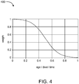
- the weight given to each lightning flash may be a function of its age, as shown in FIG. 4 .
- the newest lightning flashes may receive the greatest weight, and the weight may smoothly drop to zero as the lightning flash age approaches the dwell time.
- the weighted averaging may be designed to enforce smoothness and continuity on the mean thunderstorm object positions so that, as a history of these thunderstorm object positions accumulates, thunderstorm object velocity vectors used for forecasting may also be estimated with decent reliability.
- FIG. 4 includes a graph 400 of an example weighting function or factor which may be used to weight positions of lightning flashes as just discussed, arranged in accordance with at least one embodiment described herein.
- the weighting function of FIG. 4 inversely depends on the age of a corresponding lightning flash, or elapsed time since the corresponding lightning flash occurred.
- the weighting function of FIG. 4 drops to zero when the age of the lightning flashes reaches the dwell time, effectively aging out all lightning flashes that have an age greater than or equal to the dwell time such that relatively old lightning flashes (e.g., older than or equal to the dwell time) do not contribute to the calculation of the updated position of the corresponding thunderstorm object.
- the method 300 may be repeated one or more times, e.g., once at each update interval, with the outputs, determinations, and/or calculations from one iteration being used in one or more subsequent iterations.
- the lightning flashes newly assigned to a thunderstorm object in one iteration may be considered as previously assigned lightning flashes in a subsequent iteration.
- the updated position of a thunderstorm object determined in one iteration may be used as the most recent position of the thunderstorm object in the next iteration, e.g., when determining the distance between the thunderstorm object and new lightning flashes that are being assigned to thunderstorm objects.
- One or more outputs of the method 300 to track thunderstorms may be used to forecast future locations of thunderstorms and/or to determine severity of thunderstorms.
- the method 300 may further include forecasting a future position of a thunderstorm object based at least on an updated position of the thunderstorm object.
- Virtually any thunderstorm forecasting algorithm may be implemented and may use as input the updated position and/or a track (e.g., a series of positions over time) output by, e.g., the method 300 of FIG. 5 .
- FIG. 5 is a flowchart of an example method 500 to determine severity of a thunderstorm, arranged in accordance with at least one embodiment described herein.
- the method 500 may be performed, in whole or in part, in the system 100 of FIG. 1 , the lightning detection sensor 200 of FIG. 2 , and/or in other systems, devices, and/or configurations. Alternatively or additionally, some or all of the method 500 may be controller by a computer or processor device, such as the server 130 of FIG. 1 and/or the processor 215 of FIG. 2 .
- the method 500 may include one or more of blocks 502, 504, 506, 508, 510, and/or 512.
- the method 500 may begin at block 502.
- lightning pulses emitted by a thunderstorm object in an environmental space may be detected by lightning detection sensors.
- the lightning pulses may be grouped into lightning flashes, e.g., using any suitable algorithm.
- the lightning pulses may be detected by, e.g., the antenna 205 of FIG. 2 generating an analog signal representative of each lightning pulse received at the antenna 205.
- Block 502 may additionally include detecting the lightning flashes, such as by grouping the detected lightning pulses into lightning flashes.
- lightning data may be generated for each of the lightning pulses and the lightning flashes detected at block 502.
- the generated lightning data may include, e.g., the digital signal output by the ADC 210 of FIG. 2 for each of the lightning pulses and/or data derived therefrom, such as a position and/or time of the corresponding lightning pulse or lightning discharge from which the lightning pulse is emitted.
- the method 500 may include tracking a thunderstorm object and/or multiple thunderstorm objects.
- the tracking may be implemented according to any suitable tracking algorithm, such as the method 300 of FIG. 3 .
- the operations and/or blocks of FIG. 5 are described as being performed with respect to the lightning pulses and/or lightning flashes of a single thunderstorm object for simplicity, but may be replicated, as needed, to determine the severity of any number of thunderstorm objects.
- Block 504 may be followed by block 506.
- one or more lightning rates may be determined from the lightning data.
- the one or more lightning rates may include one or more flash rates and/or one or more pulse rates.
- one or more flash rates of the lightning flashes may be determined.
- the one or more flash rates may include a total flash rate, a CG flash rate, and/or a cloud (or pure IC) flash rate.
- Each of the foregoing flash rates may be or include the corresponding flash rate of a single thunderstorm object.
- the total flash rate may include a count of all lightning flashes of the thunderstorm object in a given time period, such as total flashes per minute.
- the CG flash rate may include a count of all CG flashes of the thunderstorm object in a given time period.
- the cloud flash rate may include a count of all cloud flashes of the thunderstorm object in a given time period.
- one or more pulse rates may be determined from the lightning data in block 506.
- the one or more pulse rates may include a total pulse rate, a CG stroke rate, and/or a cloud pulse rate.
- Each of the foregoing pulse rates may be or include the corresponding pulse rate of a single thunderstorm object.
- the total pulse rate may include a count of all lightning pulses of the thunderstorm object in a given time period.
- the CG stroke rate may include a count of all CG strokes of the thunderstorm object in a given time period.
- the cloud pulse rate may include a count of all cloud pulses of the thunderstorm object in a given time period.
- Block 506 may be followed by block 508.
- one or more lightning types may be determined from the lightning data.
- the one or more lightning types may include flash type and/or pulse type.
- the flash types may include CG flash and cloud (or pure IC) flash, while the pulse types may include CG stroke and cloud pulse.
- each of the lightning pulses may be determined to be either a cloud pulse or a CG stroke, while each of the lightning flashes may be determined to be either a cloud flash or a CG flash.
- a shape of a plot of a time-varying voltage detected for each lightning pulse, or other information in or derived from the lightning data for a given lightning pulse may be used to determine whether each pulse is a cloud pulse or a CG stroke.
- the type of each lightning flash may be determined based on whether a given lightning flash includes any CG strokes, e.g., CG flash if yes, cloud flash if no.
- Block 508 may be followed by block 510.
- one or more lightning polarities may be determined from the lightning data.
- the one or more lightning polarities may include flash polarity and/or pulse polarity.
- Each of the flash polarities and pulse polarities may include positive polarity and negative polarity.
- the sign of an initial electric field change, or other information in or derived from the lightning data for a given lightning pulse may be used to determine whether each pulse has a positive polarity or a negative polarity.
- the polarity of a lightning flash may be determined based on, e.g., the polarity of a particular pulse included in the lightning flash.
- the polarity of the first (e.g., oldest) CG stroke of the CG flash may be assigned as the polarity of the CG flash, even if the CG flash has one or more older cloud pulses.
- the polarity of the first (or oldest) cloud pulse of the cloud flash may be assigned as the polarity of the cloud flash or pure IC flash.
- Block 510 may be followed by block 512.
- the polarity of a lightning flash may be used to determine some information about the organization of the electric charges within the thunderstorm that are involved in producing the lightning flashes. For example, the presence of positively polarized lightning flashes or an increasing presence of positively polarized lightning flashes within a thunderstorm may indicate that a thunderstorm may be dissipating.
- the severity determination in block 512 is a binary determination, e.g., the thunderstorm is determined to be either severe or not severe and may be based on rates, types, and/or polarities included in or derived from the lightning data.
- Some algorithms to determine severity based on lightning data use only the flash rate or time rate of change of the flash rate to determine the severity. Such algorithms rely on total flash rate or rapid increases in total flash rate as indicators of severity.
- An example algorithm defines a flash rate criterion as a two-minute interval of time in which a time rate of change of a total flash rate of a thunderstorm object is at least two standard deviations above a weighted, running average of the time rate of change of the total flash rate during a preceding 10 minutes.
- a variation of the preceding algorithm dispenses with the weighted smoothing and adds a minimum total flash rate to the flash rate criterion, the variation of the flash rate criterion being defined as a two-minute interval in which a time rate of change of the total flash rate is at least two standard deviations above the average of the time rate of change of the total flash rate during the preceding 10 minutes and the total flash rate being at least 10 flashes per minute.
- a thunderstorm object with lightning data that satisfies the flash rate criterion may be determined to be a severe thunderstorm, while a thunderstorm object with lightning data that fails to satisfy the flash rate criterion may be determined to not be a severe thunderstorm.
- such algorithms to determine thunderstorm severity based on lightning data fail to take into consideration two other characteristics of lightning that may be included in or derived from lightning data, namely, type and polarity. Embodiments described herein, however, may determine the severity based on the flash rate (and/or pulse rate), the types, and the polarities of lightning pulses and/or flashes of the thunderstorm.
- determining the severity of the thunderstorm at block 512 based on the determined rates, types, and polarities may include determining whether the flash rate and/or a time rate of change of the flash rate satisfy a flash rate criterion, determining whether the types and/or polarities satisfy at least a second criterion, and determining that the thunderstorm object is severe or not severe based on whether the flash rate criterion and the second criterion are satisfied. In an embodiment, it may be determined that the thunderstorm object is not severe in response to the total flash rate or the time rate of change of the total flash rate failing to satisfy the flash rate criterion.
- the thunderstorm object is severe in response to the total flash rate or the time rate of change of the total flash rate satisfying the flash rate criterion and the types and/or polarities satisfying the second criterion.
- a method may comprise determining that the thunderstorm object is severe or not severe based on whether the flash rate criterion and the at least the second criterion are satisfied, further comprising determining that the thunderstorm object is not severe in response to the total flash rate or the time rate of change of the total flash rate satisfying the flash rate criterion and the types and/or polarities failing to satisfy the at least the second criterion.
- the flash rate criterion may comprise the time rate of change of the total flash rate during a two-minute interval being at least two standard deviations above an average of the time rate of change of the total flash rate during a preceding 10 minute interval and the total flash rate being at least 10 flashes per minute, the at least second criterion comprises at least one of: the total flash rate is at least 30 flashes per two-minute interval and a fraction of cloud flashes among the plurality of flashes is at least 0.5 and greater than or equal to a threshold that decreases linearly with increasing total flash rate, a pulse rate of cloud pulses with negative polarity and associated with cloud flashes is greater than or equal to a second threshold that decreases linearly with increasing total flash rate, or the total flash rate is at least 55 flashes per two-minute interval.
- the flash rate criterion used in determining the severity of the thunderstorm in block 512 may be the same as or similar to one or more of the flash rate criteria discussed elsewhere.
- the flash rate criterion may include the time rate of change of the total flash rate during a two-minute interval being at least two standard deviations above an average of the time rate of change of the total flash rate during a preceding 10 minute interval and the total flash rate being at least 10 flashes per minute.
- the second criterion may include at least one of the following: (1) the total flash rate is at least 30 flashes per two-minute interval and a fraction of cloud flashes among all flashes is at least 0.5 and greater than or equal to a threshold that decreases linearly with increasing total flash rate, (2) a pulse rate of cloud pulses with negative polarity and associated with cloud flashes is greater than or equal to a second threshold that decreases linearly with increasing total flash rate, and/or (3) the total flash rate is at least 55 flashes per two-minute interval.
- the second criterion may include any criterion that includes or is based on rate, type, and/or polarity in virtually any combination.
- rate rate
- type type
- polarity polarity
- determining the severity of the thunderstorm at block 512 based on the determined rates, types, and polarities may include determining a flash rate of lightning flashes having a specific flash type, such as a CG flash rate or a cloud flash rate.
- the determining at block 512 may include determining a CG flash rate or a cloud flash rate, where the severity of the thunderstorm may depend on the determined CG flash rate or cloud flash rate.
- the determining at block 512 may include determining a pulse rate of lightning pulses having a specific pulse type, such as CG stroke rate or cloud pulse rate.
- the determining at block 512 may include determining a CG stroke rate or a cloud pulse rate, where the severity of the thunderstorm may depend on the determined CG stroke rate or cloud pulse rate.
- the determining at block 512 may include determining a ratio of lightning flashes having a specific flash type to a total number of flashes. For instance, the determining at block 512 may include determining a ratio of CG flashes or cloud flashes to a total number of the lightning flashes, where the severity of the thunderstorm may depend on the determined ratio.
- the determining at block 512 may include determining a ratio of lightning flashes having a specific flash type and a specific polarity to a total number of flashes having the specific polarity. For instance, the determining at block 512 may include determining a ratio of positive polarity CG flashes or of negative polarity CG flashes to a total number of CG flashes, where the severity of the thunderstorm may depend on the determined ratio. Alternatively or additionally, the determining at block 512 may include determining a ratio of positive polarity cloud flashes or of negative polarity cloud flashes to a total number of cloud flashes, where the severity of the thunderstorm may depend on the determined ratio.
- the determining at block 512 may include determining a time rate of change of all lightning flashes, or determining a time rate of change of lightning flashes having a specific flash type (e.g., CG flash or cloud flash).
- a specific flash type e.g., CG flash or cloud flash.
- the determining at block 512 may include determining a flash rate of lightning flashes having a specific polarity, such as positive or negative polarity. For instance, the determining at block 512 may include determining a flash rate of negative polarity lightning flashes or of positive polarity lightning flashes, where the severity of the thunderstorm may depend on the determined flash rate of negative or positive polarity lightning flashes.
- the determining at block 512 may include determining a pulse rate of lightning pulses having a specific type and polarity.
- the determining at block 512 may include determining a pulse rate of negative polarity CG strokes or of positive polarity CG strokes, where the severity of the thunderstorm may depend on the determined pulse rate of negative or positive polarity CG strokes.
- the determining at block 512 may include determining a pulse rate of negative polarity cloud pulses or of positive polarity cloud pulses, where the severity of the thunderstorm may depend on the determined pulse rate of negative or positive polarity cloud pulses.
- the determining at block 512 may include determining a ratio of lightning flashes having the specific polarity (e.g., positive or negative) to a total number of flashes.
- the determining at block 512 may include determining a time rate of change of the lightning flashes having the specific polarity (e.g., positive or negative).
- the determining at block 512 may include determining a ratio of a specific type of lightning pulses associated with the specific type of lightning flashes to a total number of the specific type of lightning pulses. For instance, the determining at block 512 may include determining a ratio of cloud pulses or CG strokes associated with cloud flashes or CG flashes to a total number of cloud flashes or CG flashes, where the severity of the thunderstorm may depend on the determined ratio.
- the determining at block 512 may include determining a ratio of a specific polarity and type of lightning pulses associated with the specific type of lightning flashes to a total number of the specific type of lightning pulses. For instance, the determining at block 512 may include determining a ratio of negative polarity cloud pulses associated with cloud flashes to a total number of cloud pulses, where the severity of the thunderstorm may depend on the determined ratio.
- the determined severity may be used in connection with one or both of the tracking and/or forecasting.
- thunderstorms may be tracked with the tracking algorithm, forecasted with a short-term forecasting algorithm, and have their severity determined to provide a warning, notice, and/or forecast to the public, utilities, airports, government officials, and/or other entities in forecasted future locations (and/or surrounding areas) of a severe thunderstorm.
- the server 130 may send one or more electronic messages or post data to a webpage stating the severity of a thunderstorm and/or the track of the thunderstorm.
- the severity metric may be output from the server 130 to the user interface device 135.
- Embodiments of the methods described herein may be applied to a database of historical lightning data to determine how well the tracking, forecasting, and/or severity determination methods and operations described herein align with actual historical results.
- lightning data may be stored in a database.
- lightning data collected and/or generated as described herein may be added to such a database.
- determining whether an identified thunderstorm is severe may be based on a statistical analysis based on a number of different factors such as, for example, one or more of the pressure, temperature, humidity, wind, the density of lightning flashes, the type of lightning flashes, the polarity of lightning flashes, etc. in addition to one or more of, e.g., the criteria discussed with respect to FIG. 5 .
- FIG. 6 includes a block diagram of an example computational system 600 (or processing unit), arranged in accordance with at least one embodiments described herein.
- the computational system 600 can be used to perform and/or control operation of any of the embodiments described herein.
- the computational system 600 can be used alone or in conjunction with other components.
- the computational system 600 can be used to perform any calculation, solve any equation, perform any identification, and/or make any determination described here.
- the computational system 600 is an example implementation of the server 130 of FIG. 1 .
- the computational system 600 may include any or all of the hardware elements shown in the figure and described herein.
- the computational system 600 may include hardware elements that can be electrically coupled via a bus 605 (or may otherwise be in communication, as appropriate).
- the hardware elements can include one or more processors 610, including one or more general-purpose processors and/or one or more special-purpose processors (such as digital signal processing chips, graphics acceleration chips, and/or the like); one or more input devices 615, which can include a mouse, a keyboard, or other suitable input device; and one or more output devices 620, which can include a display device, a printer, and/or other suitable output device.
- the computational system 600 may further include (and/or be in communication with) one or more storage devices 625, which can include local and/or network-accessible storage and/or can include a disk drive, a drive array, an optical storage device, a solid-state storage device, such as random access memory (“RAM”) and/or read-only memory (“ROM”), which can be programmable, flash-updateable, and/or the like.
- storage devices 625 can include local and/or network-accessible storage and/or can include a disk drive, a drive array, an optical storage device, a solid-state storage device, such as random access memory (“RAM”) and/or read-only memory (“ROM”), which can be programmable, flash-updateable, and/or the like.
- the computational system 600 might also include a communications subsystem 630, which can include a modem, a network card (wireless or wired), an infrared communication device, a wireless communication device, and/or chipset (such as a Bluetooth® device, a 802.6 device, a Wi-Fi device, a WiMAX device, cellular communication facilities, etc.), and/or the like.
- the communications subsystem 630 may permit data to be exchanged with a network (such as the networks described elsewhere herein) and/or any other systems and/or devices described herein.
- the computational system 600 may further include a working memory 635, which can include a RAM or ROM device, as described above.
- the computational system 600 also can include software elements, shown as being currently located within the working memory 635, including an operating system 640 and/or other code, such as one or more application programs 645, which may include computer programs of the invention, and/or may be designed to implement methods of the invention and/or configure systems of the invention, as described herein.
- an operating system 640 and/or other code such as one or more application programs 645, which may include computer programs of the invention, and/or may be designed to implement methods of the invention and/or configure systems of the invention, as described herein.
- application programs 645 which may include computer programs of the invention, and/or may be designed to implement methods of the invention and/or configure systems of the invention, as described herein.
- one or more operations or procedures described with respect to the method(s) discussed above might be implemented as code and/or instructions executable by a computer (and/or a processor within a computer).
- a set of these instructions and/or codes might be stored on a computer-readable storage medium, such as the storage device(s)
- the storage medium might be incorporated within the computational system 600 or in communication with the computational system 600.
- the storage medium might be separate from the computational system 600 (e.g., a removable medium, such as a compact disc, etc.), and/or provided in an installation package, such that the storage medium can be used to program a general-purpose computer with the instructions/code stored thereon.
- These instructions might take the form of executable code, which is executable by the computational system 600 and/or might take the form of source and/or installable code, which, upon compilation and/or installation on the computational system 600 (e.g., using any of a variety of generally available compilers, installation programs, compression/decompression utilities, etc.), then takes the form of executable code.
- a computing device can include any suitable arrangement of components that provides a result conditioned on one or more inputs.
- Suitable computing devices include multipurpose microprocessor-based computer systems accessing stored software that programs or configures the computing system from a general-purpose computing apparatus to a specialized computing apparatus implementing one or more embodiments of the present subject matter. Any suitable programming, scripting, or other type of language or combinations of languages may be used to implement the teachings contained herein in software to be used in programming or configuring a computing device.
- Embodiments of the methods disclosed herein may be performed in the operation of such computing devices.
- the order of the blocks presented in the examples above can be varied-for example, blocks can be re-ordered, combined, and/or broken into sub-blocks. Certain blocks or processes can be performed in parallel.
Landscapes
- Environmental & Geological Engineering (AREA)
- Engineering & Computer Science (AREA)
- Life Sciences & Earth Sciences (AREA)
- Atmospheric Sciences (AREA)
- Biodiversity & Conservation Biology (AREA)
- Ecology (AREA)
- Environmental Sciences (AREA)
- Radar Systems Or Details Thereof (AREA)
Claims (14)
- Verfahren zum Verfolgen von Gewittern, wobei das Verfahren Folgendes umfasst:Detektieren (302) einer Vielzahl von Blitzeinschlägen in einem Umweltraum unter Verwendung einer Vielzahl von Blitzdetektionssensoren (105, 110, 115, 120, 200) über einen Zeitraum;Erzeugen (304) von Blitzdaten für jeden der Vielzahl von Blitzeinschlägen, wobei die Blitzdaten für jeden der Vielzahl von Blitzeinschlägen sowohl eine Position als auch eine Zeit für jeden der Vielzahl von Blitzeinschlägen enthalten;Zuordnen (306) der Vielzahl von Blitzeinschlägen zu einer Vielzahl von Gewitterobjekten, enthaltend das Zuordnen eines gegebenen Blitzeinschlags der Vielzahl von Blitzeinschlägen zu einem gegebenen Gewitterobjekt der Vielzahl von Gewitterobjekten, dadurch gekennzeichnet, dass die Zuordnung des Blitzeinschlags auf Folgendem basiert:einer Reihe dem gegebenen Gewitterobjekt zugeordneter früherer Blitzeinschläge; undeinem Abstand zwischen dem gegebenen Blitzeinschlag und dem gegebenen Gewitterobjekt, wobei der Abstand basierend auf einer jüngsten Position des gegebenen Gewitterobjekts und einer Position des gegebenen Blitzeinschlags, enthalten in entsprechenden Blitzdaten des gegebenen Blitzeinschlags, bestimmt wird; undBestimmen (308) einer aktualisierten Position des gegebenen Gewitterobjekts basierend auf Positionen und Lebensdauern dem gegebenen Gewitterobjekt zugeordneter Blitzeinschläge, enthaltend den gegebenen Blitzeinschlag.
- Verfahren nach Anspruch 1, wobei das Bestimmen (308) der aktualisierten Position des gegebenen Gewitterobjekts basierend auf den Positionen der dem gegebenen Gewitterobjekt zugeordneten Blitzeinschläge Folgendes umfasst:Gewichten der Positionen der dem gegebenen Gewitterobjekt zugeordneten Blitzeinschläge gemäß einer verstrichenen Zeit seit dem Auftreten eines entsprechenden Blitzeinschlags; undBerechnen, als aktualisierte Position des gegebenen Gewitterobjekts, eines gewichteten Durchschnitts der Positionen der dem gegebenen Gewitterobjekt zugeordneten Blitzeinschläge durch Berechnen des Durchschnitts der gewichteten Positionen der dem gegebenen Gewitterobjekt zugeordneten Blitzeinschläge.
- Verfahren nach Anspruch 1, wobei das Bestimmen (308) der aktualisierten Position des gegebenen Gewitterobjekts basierend auf Positionen und Lebensdauern dem gegebenen Gewitterobjekt zugeordneter Blitzeinschläge Folgendes umfasst:Gewichten von Positionen der dem gegebenen Gewitterobjekt zugeordneten Blitzeinschläge mit einem Gewichtungsfaktor (400), der reziprok von einer Menge der verstrichenen Zeit seit dem Auftreten eines entsprechenden Blitzeinschlags abhängt; undBestimmen der aktualisierten Position des gegebenen Gewitterobjekts basierend auf den gewichteten Positionen der dem gegebenen Gewitterobjekt zugeordneten Blitzeinschläge.
- Verfahren nach Anspruch 3, wobei das Gewichten von Positionen der dem gegebenen Gewitterobjekt zugeordneten Blitzeinschläge mit dem Gewichtungsfaktor (400), der reziprok von der Menge der verstrichenen Zeit seit dem Auftreten eines entsprechenden Blitzeinschlags abhängt, das Gewichten von Positionen der dem gegebenen Gewitterobjekt zugeordneten Blitzeinschläge gemäß einer Gewichtungsfunktion (400), die als Funktion der verstrichenen Zeit gleichmäßig von einem maximalen Gewichtungswert bei einer anfänglichen verstrichenen Zeit auf einen minimalen Gewichtungswert bei einer definierten Verweilzeit fällt, umfasst.
- Verfahren nach Anspruch 3, wobei das Gewichten von Positionen der dem gegebenen Gewitterobjekt zugeordneten Blitzeinschläge mit dem Gewichtungsfaktor (400), der reziprok von der Menge der verstrichenen Zeit seit dem Auftreten des entsprechenden Blitzeinschlags abhängt, das Zuordnen eines Gewichts von Null zu Positionen aller dem gegebenen Gewitterobjekt zugeordneten Blitzeinschläge umfasst, die eine verstrichene Zeit aufweisen, die länger ist als eine definierte Verweilzeit.
- Verfahren nach Anspruch 1, wobei das Zuordnen (306) der Vielzahl von Blitzeinschlägen zu der Vielzahl von Gewitterobjekten für jeden der Vielzahl von Blitzeinschlägen Folgendes umfasst:Berechnen einer Vielzahl von Kräften zwischen einem entsprechenden Blitzeinschlag und der Vielzahl von Gewitterobjekten, wobei jede der Vielzahl von Kräften eine Anziehung zwischen dem entsprechenden Blitzeinschlag und einem anderen der Vielzahl von Gewitterobjekten darstellt;Bestimmen, welche der Vielzahl von Kräften am größten ist; undZuordnen des entsprechenden Blitzeinschlags zu einem gegebenen der Vielzahl von Gewitterobjekten, das die größte der Vielzahl von Kräften bei dem entsprechenden Blitzeinschlag aufweist.
- Verfahren nach Anspruch 6, wobei das Berechnen jeder der Vielzahl von Kräften das Berechnen, für jeden entsprechenden Blitzeinschlag und jedes entsprechende Gewitterobjekt, einer Reihe dem entsprechenden Gewitterobjekt zugeordneter früherer Blitzeinschläge geteilt durch das Quadrat des Abstands zwischen dem entsprechenden Blitzeinschlag und dem entsprechenden Gewitterobjekt umfasst.
- Verfahren nach Anspruch 1, weiter umfassend das Bestimmen (500) eines Schweregrads eines Gewitterobjekts der Vielzahl von Gewitterobjekten, umfassend:Detektieren (502) einer Vielzahl von Blitzimpulsen des Gewitterobjekts unter Verwendung der Vielzahl von Blitzdetektionssensoren (105, 110, 115, 120, 200), wobei die Vielzahl von Blitzimpulsen in die Vielzahl von Blitzeinschlägen gruppiert ist;Erzeugen (504) von Blitzdaten für jeden der Vielzahl von Blitzimpulsen und jeden der Vielzahl von Blitzeinschlägen;Bestimmen (506) einer oder mehrerer Blitzraten aus den Blitzdaten;Bestimmen (508) einer oder mehrerer Blitzarten aus den Blitzdaten;Bestimmen (510) einer oder mehrerer Blitzpolaritäten aus den Blitzdaten; undBestimmen (512) eines Schweregrads des Gewitterobjekts basierend auf den bestimmten Raten, Arten und Polaritäten.
- Verfahren nach Anspruch 8, wobei das Bestimmen (512) des Schweregrads des Gewitterobjekts basierend auf den bestimmten Raten, Arten und Polaritäten das Bestimmen des Schweregrads des Gewitterobjekts basierend auf einem oder mehreren der folgenden, enthalten in oder abgeleitet von den Raten, den Arten und/oder den Polaritäten, enthält:einer Gesamteinschlagrate der Vielzahl von Blitzeinschlägen;einer zeitlichen Veränderungsrate der Gesamteinschlagrate;einer Einschlagrate der Vielzahl von Blitzeinschlägen mit einer spezifischen Einschlagart;einem Verhältnis der Vielzahl von Blitzeinschlägen mit der spezifischen Einschlagart zu einer Gesamtanzahl der Vielzahl von Blitzeinschlägen;einer zeitlichen Veränderungsrate der Vielzahl von Blitzeinschlägen mit der spezifischen Einschlagart;einer Einschlagrate der Vielzahl von Blitzeinschlägen mit einer spezifischen Polarität;einem Verhältnis der Vielzahl von Blitzeinschlägen mit der spezifischen Polarität zu der Gesamtanzahl der Vielzahl von Blitzeinschlägen undeiner zeitlichen Veränderungsrate der Vielzahl von Blitzeinschlägen mit der spezifischen Polarität.
- Verfahren nach Anspruch 8, wobei das Bestimmen (508) einer oder mehrerer Blitzarten aus den Blitzdaten das Bestimmen einer Einschlagart jedes der Vielzahl von Blitzeinschlägen und das Bestimmen einer Impulsart jedes der Vielzahl von Blitzimpulsen enthält und wobei:die Einschlagart jedes der Vielzahl von Blitzeinschlägen ausgewählt ist aus der Liste, bestehend aus einem Wolkeneinschlag und einem Wolke-Erde-Einschlag; unddie Impulsart jedes der Vielzahl von Blitzimpulsen ausgewählt ist aus der Liste, bestehend aus einem Wolkenimpuls und einem Wolke-Erde-Blitzschlag.
- Verfahren nach Anspruch 10, wobei das Bestimmen der Einschlagart jedes der Vielzahl von Blitzeinschlägen aus den Blitzdaten Folgendes umfasst:Bestimmen, für jeden entsprechenden Blitzeinschlag der Vielzahl von Blitzeinschlägen, ob mindestens ein in den entsprechenden Blitzeinschlag gruppierter Blitzimpuls eine Wolke-Erde-Blitzschlag-Art aufweist; undeines von Folgendem:Bestimmen, dass der entsprechende Blitzeinschlag eine Wolke-Erde-Einschlag-Art aufweist, die auf mindestens einen Blitzimpuls reagiert, der in den entsprechenden Blitzeinschlag, der die Wolke-Erde-Blitzschlag-Art aufweist, gruppiert ist; oderBestimmen, dass der entsprechende Blitzeinschlag eine Wolkeneinschlagart aufweist, die auf keine Blitzimpulse reagiert, die in den entsprechenden Blitzeinschlag, der die Wolke-Erde-Blitzschlag-Art aufweist, gruppiert sind.
- Verfahren nach Anspruch 8, wobei:
das Bestimmen (512) des Schweregrads des Gewitterobjekts basierend auf den bestimmten Raten, Arten und Polaritäten Folgendes umfasst:Bestimmen, ob eine Gesamteinschlagrate der Vielzahl von Blitzeinschlägen und/oder eine zeitliche Veränderungsrate der Gesamteinschlagrate ein Einschlagratenkriterium erfüllt/erfüllen;Bestimmen, ob die Arten und/oder Polaritäten ein zweites Kriterium erfüllen, das mindestens eines von Folgendem enthält:die Gesamteinschlagrate beträgt mindestens 30 Einschläge pro Zwei-Minuten-Intervall und ein Anteil von Wolkeneinschlägen beträgt mindestens 0,5 und ist größer als oder gleich einem ersten Schwellenwert, der linear zu einer ansteigenden Gesamteinschlagrate sinkt;eine Impulsrate von Wolkenimpulsen mit negativer Polarität und verbunden mit Wolkeneinschlägen ist größer als oder gleich einem zweiten Schwellenwert, der linear zu einer ansteigenden Gesamteinschlagrate sinkt; oderdie Gesamteinschlagrate beträgt mindestens 55 Einschläge pro Zwei-Minuten-Intervall; undBestimmen, dass das Gewitterobjekt schwerwiegend oder nicht schwerwiegend ist, basierend darauf, ob das Einschlagratenkriterium und das zweite Kriterium erfüllt sind. - Verfahren nach Anspruch 12, wobei das Bestimmen, dass das Gewitterobjekt schwerwiegend oder nicht schwerwiegend ist, basierend darauf, ob das Einschlagratenkriterium und das zweite Kriterium erfüllt sind, Folgendes umfasst:Bestimmen, dass das Gewitterobjekt nicht schwerwiegend ist, in Reaktion darauf, dass die Gesamteinschlagrate oder die zeitliche Veränderungsrate der Gesamteinschlagrate das Einschlagratenkriterium nicht erfüllt; undBestimmen, dass das Gewitterobjekt schwerwiegend ist, in Reaktion darauf, dass die Gesamteinschlagrate oder die zeitliche Veränderungsrate der Gesamteinschlagrate das Einschlagratenkriterium erfüllt und die Arten und/oder Polaritäten das zweite Kriterium erfüllen.
- Blitzdetektionssystem (100), umfassend:eine Vielzahl von Blitzdetektionssensoren (105, 110, 115, 120, 200), die konfiguriert sind, eine Vielzahl von Blitzimpulsen eines Gewitterobjekts zu detektieren, wobei die Vielzahl der Blitzimpulse in eine Vielzahl von Blitzeinschlägen gruppiert ist;eine Prozessorvorrichtung (215, 610), die kommunikativ mit der Vielzahl von Blitzdetektionssensoren gekoppelt ist und konfiguriert ist, um:eine Vielzahl von Gewitterobjekten zu verfolgen (300), enthaltend:Zuordnen (306) der Vielzahl von Blitzeinschlägen zu der Vielzahl von Gewitterobjekten basierend auf der Anzahl der jedem der Vielzahl von Gewitterobjekten zugeordneten früheren Blitzeinschläge und einem Abstand zwischen jedem der Vielzahl von Blitzeinschlägen und jedem der Vielzahl von Gewitterobjekten; undBestimmen (308) einer aktualisierten Position jedes der Vielzahl von Gewitterobjekten basierend auf Positionen und Lebensdauern jedem der Vielzahl von Gewitterobjekten zugeordneter Blitzeinschläge; undeinen Schweregrad eines oder mehrerer der Gewitterobjekte basierend auf Blitzraten, Arten und/oder Polaritäten von Blitzeinschlägen und/oder Blitzimpulsen der Gewitterobjekte zu bestimmen (512).
Applications Claiming Priority (2)
| Application Number | Priority Date | Filing Date | Title |
|---|---|---|---|
| US201662368625P | 2016-07-29 | 2016-07-29 | |
| US15/647,065 US10782448B2 (en) | 2016-07-29 | 2017-07-11 | Short-term thunderstorm forecast and severe weather alert system and method |
Publications (2)
| Publication Number | Publication Date |
|---|---|
| EP3276382A1 EP3276382A1 (de) | 2018-01-31 |
| EP3276382B1 true EP3276382B1 (de) | 2019-07-17 |
Family
ID=59366293
Family Applications (1)
| Application Number | Title | Priority Date | Filing Date |
|---|---|---|---|
| EP17181813.1A Active EP3276382B1 (de) | 2016-07-29 | 2017-07-18 | Kurzfristige gewittervorhersage und unwetterwarnsystem und verfahren |
Country Status (2)
| Country | Link |
|---|---|
| US (1) | US10782448B2 (de) |
| EP (1) | EP3276382B1 (de) |
Families Citing this family (16)
| Publication number | Priority date | Publication date | Assignee | Title |
|---|---|---|---|---|
| US10718613B2 (en) * | 2016-04-19 | 2020-07-21 | Massachusetts Institute Of Technology | Ground-based system for geolocation of perpetrators of aircraft laser strikes |
| CN109061774B (zh) * | 2018-06-26 | 2020-10-16 | 合肥佳讯科技有限公司 | 一种雷暴核关联性处理方法 |
| CN109613630B (zh) * | 2018-10-15 | 2021-05-18 | 杭州易造科技有限公司 | 大气电场实时监控报警系统 |
| CN109599852B (zh) * | 2018-12-05 | 2019-12-17 | 北京雷布斯雷电安全科技有限公司 | 防雷系统 |
| CN109725371A (zh) * | 2018-12-24 | 2019-05-07 | 深圳市六韬天气科技有限公司 | 基于低频流场图的华南地区台风和暴雨的预测方法 |
| CN111290053B (zh) * | 2020-02-29 | 2021-12-17 | 华南理工大学 | 一种基于卡尔曼滤波的雷暴路径预测方法 |
| CN113203896B (zh) * | 2021-05-19 | 2023-10-03 | 贵州省气象灾害防御技术中心 | 单站大气电场仪进行雷电预警的阈值法检验及改进方法 |
| CN113484934B (zh) * | 2021-06-08 | 2023-12-29 | 北京华云东方探测技术有限公司 | 雷暴观测数据的确定方法、系统、电子设备及存储介质 |
| CN114019514B (zh) * | 2021-11-25 | 2022-11-01 | 浙江省气象台 | 一种雷暴大风预警方法、系统、设备及终端 |
| CN114019255B (zh) * | 2022-01-10 | 2022-03-11 | 中科边缘智慧信息科技(苏州)有限公司 | 一种雷暴中心的定位和预测方法及系统 |
| CN116132432B (zh) * | 2023-04-19 | 2023-07-04 | 中国气象局气象探测中心 | 一种面向云端协同的雷暴告警图片生成算法设计方法 |
| CN116894160B (zh) * | 2023-07-24 | 2025-08-01 | 中国南方电网有限责任公司超高压输电公司电力科研院 | 一种区域雷暴影响分析系统 |
| CN117932989B (zh) * | 2024-03-25 | 2024-05-17 | 南京信息工程大学 | 一种基于Bezier曲线的雷暴路径预测方法 |
| CN119004117B (zh) * | 2024-10-23 | 2025-01-17 | 杭州电子科技大学 | 一种基于模糊c均值聚类的雷暴时间窗口捕捉方法 |
| CN119004047B (zh) * | 2024-10-23 | 2025-02-07 | 杭州电子科技大学 | 一种时空域雷暴活动解释方法 |
| CN119902158B (zh) * | 2025-02-07 | 2025-10-14 | 中国科学院大气物理研究所 | 移动式雷电三维定位系统及方法 |
Family Cites Families (9)
| Publication number | Priority date | Publication date | Assignee | Title |
|---|---|---|---|---|
| US5610813A (en) | 1994-10-06 | 1997-03-11 | B. F. Goodrich Flightsystems, Inc. | Thunderstorm cell detection and mapping system for identifying and ranging thunderstorm cells by clustering single strike lightning observations |
| US6791311B2 (en) | 2002-02-13 | 2004-09-14 | Vaisala Oyj | Lightning detection and data acquisition system |
| US7515087B1 (en) * | 2006-03-07 | 2009-04-07 | Rockwell Collins, Inc. | Weather radar system and method using data from a lightning sensor |
| US8010289B1 (en) * | 2005-07-19 | 2011-08-30 | Avidyne Corporation | Method and apparatus for detecting and processing lightning |
| US7970542B2 (en) * | 2007-04-17 | 2011-06-28 | Toa Systems, Inc. | Method of detecting, locating, and classifying lightning |
| US8344721B2 (en) * | 2010-01-07 | 2013-01-01 | Vaisala Oyj | Method for locating sub-surface natural resources |
| US8836518B2 (en) | 2011-07-06 | 2014-09-16 | Earth Networks, Inc. | Predicting the potential for severe weather |
| CN104169744B (zh) * | 2012-01-18 | 2017-10-31 | 地球网络股份有限公司 | 使用闪电数据生成替代反射率数据 |
| US10302815B1 (en) * | 2015-10-01 | 2019-05-28 | Rockwell Collins, Inc. | System and method of integrating global convective weather |
-
2017
- 2017-07-11 US US15/647,065 patent/US10782448B2/en active Active
- 2017-07-18 EP EP17181813.1A patent/EP3276382B1/de active Active
Non-Patent Citations (1)
| Title |
|---|
| None * |
Also Published As
| Publication number | Publication date |
|---|---|
| EP3276382A1 (de) | 2018-01-31 |
| US20180031737A1 (en) | 2018-02-01 |
| US10782448B2 (en) | 2020-09-22 |
Similar Documents
| Publication | Publication Date | Title |
|---|---|---|
| US10782448B2 (en) | Short-term thunderstorm forecast and severe weather alert system and method | |
| KR101929990B1 (ko) | 악천후에 대한 가능성의 예측 | |
| Rudlosky et al. | Documenting storm severity in the mid-Atlantic region using lightning and radar information | |
| US10359543B2 (en) | Forecasting lightning activity | |
| US10761242B1 (en) | Systems and methods for forecasting lightning and severe storms | |
| Qie et al. | Recent advances in research of lightning meteorology | |
| US10317574B2 (en) | System and method for identification and/or nowcasting of hail events | |
| Ferro et al. | Lightning risk warnings based on atmospheric electric field measurements in Brazil | |
| Gravelle et al. | Demonstration of a GOES-R satellite convective toolkit to “bridge the gap” between severe weather watches and warnings: An example from the 20 May 2013 Moore, Oklahoma, tornado outbreak | |
| San Segundo et al. | Sensitivity analysis of lightning stroke-to-flash grouping criteria | |
| Murphy et al. | Cloud-to-ground lightning warnings using electric field mill and lightning observations | |
| Pédeboy et al. | Analysis of the intra-cloud lightning activity detected with low frequency lightning locating systems | |
| Harkema et al. | Geostationary Lightning Mapper flash characteristics of electrified snowfall events | |
| Bloemink | Static electricity measurements for lightning warnings-an exploration | |
| Hartung et al. | An intercomparison of UW cloud-top cooling rates with WSR-88D radar data | |
| KR102156309B1 (ko) | 해안 해수면을 관측하기 위한 전자 장치 및 방법 | |
| Ruiz et al. | A quality control algorithm for the Osaka Phased Array Weather Radar | |
| Roeder et al. | Four dimensional lightning surveillance system: status and plans | |
| US10746772B2 (en) | Identification of cloud-to-ground lightning strokes with continuing current | |
| Heckman et al. | Earth networks lightning overview | |
| Vitalii et al. | WRF reflectivity simulation and verification of thunderstorm forecast by radar and surface observation | |
| Taori et al. | Detection of atmospheric lightning activity with ground-based radiofrequency receivers—establishment and initial results | |
| Chkeir et al. | A New Extreme Weather Nowcasting Product Supporting Aviation Management at Local Scale | |
| Patton et al. | Using Radar-Derived Parameters to Develop Probabilistic Guidance for Lightning Cessation within Isolated Convection near Cape Canaveral, Florida | |
| Schatz et al. | Prediction of first cloud-to-ground flashes and determination of all-clear timing for lightning risk in regional convective thunderstorms |
Legal Events
| Date | Code | Title | Description |
|---|---|---|---|
| PUAI | Public reference made under article 153(3) epc to a published international application that has entered the european phase |
Free format text: ORIGINAL CODE: 0009012 |
|
| STAA | Information on the status of an ep patent application or granted ep patent |
Free format text: STATUS: REQUEST FOR EXAMINATION WAS MADE |
|
| 17P | Request for examination filed |
Effective date: 20170718 |
|
| AK | Designated contracting states |
Kind code of ref document: A1 Designated state(s): AL AT BE BG CH CY CZ DE DK EE ES FI FR GB GR HR HU IE IS IT LI LT LU LV MC MK MT NL NO PL PT RO RS SE SI SK SM TR |
|
| AX | Request for extension of the european patent |
Extension state: BA ME |
|
| GRAP | Despatch of communication of intention to grant a patent |
Free format text: ORIGINAL CODE: EPIDOSNIGR1 |
|
| STAA | Information on the status of an ep patent application or granted ep patent |
Free format text: STATUS: GRANT OF PATENT IS INTENDED |
|
| INTG | Intention to grant announced |
Effective date: 20190321 |
|
| GRAS | Grant fee paid |
Free format text: ORIGINAL CODE: EPIDOSNIGR3 |
|
| GRAA | (expected) grant |
Free format text: ORIGINAL CODE: 0009210 |
|
| STAA | Information on the status of an ep patent application or granted ep patent |
Free format text: STATUS: THE PATENT HAS BEEN GRANTED |
|
| AK | Designated contracting states |
Kind code of ref document: B1 Designated state(s): AL AT BE BG CH CY CZ DE DK EE ES FI FR GB GR HR HU IE IS IT LI LT LU LV MC MK MT NL NO PL PT RO RS SE SI SK SM TR |
|
| REG | Reference to a national code |
Ref country code: GB Ref legal event code: FG4D |
|
| REG | Reference to a national code |
Ref country code: CH Ref legal event code: EP |
|
| REG | Reference to a national code |
Ref country code: IE Ref legal event code: FG4D |
|
| REG | Reference to a national code |
Ref country code: DE Ref legal event code: R096 Ref document number: 602017005297 Country of ref document: DE |
|
| REG | Reference to a national code |
Ref country code: AT Ref legal event code: REF Ref document number: 1156372 Country of ref document: AT Kind code of ref document: T Effective date: 20190815 |
|
| REG | Reference to a national code |
Ref country code: NL Ref legal event code: MP Effective date: 20190717 |
|
| REG | Reference to a national code |
Ref country code: LT Ref legal event code: MG4D |
|
| REG | Reference to a national code |
Ref country code: AT Ref legal event code: MK05 Ref document number: 1156372 Country of ref document: AT Kind code of ref document: T Effective date: 20190717 |
|
| PG25 | Lapsed in a contracting state [announced via postgrant information from national office to epo] |
Ref country code: HR Free format text: LAPSE BECAUSE OF FAILURE TO SUBMIT A TRANSLATION OF THE DESCRIPTION OR TO PAY THE FEE WITHIN THE PRESCRIBED TIME-LIMIT Effective date: 20190717 Ref country code: AT Free format text: LAPSE BECAUSE OF FAILURE TO SUBMIT A TRANSLATION OF THE DESCRIPTION OR TO PAY THE FEE WITHIN THE PRESCRIBED TIME-LIMIT Effective date: 20190717 Ref country code: SE Free format text: LAPSE BECAUSE OF FAILURE TO SUBMIT A TRANSLATION OF THE DESCRIPTION OR TO PAY THE FEE WITHIN THE PRESCRIBED TIME-LIMIT Effective date: 20190717 Ref country code: FI Free format text: LAPSE BECAUSE OF FAILURE TO SUBMIT A TRANSLATION OF THE DESCRIPTION OR TO PAY THE FEE WITHIN THE PRESCRIBED TIME-LIMIT Effective date: 20190717 Ref country code: NO Free format text: LAPSE BECAUSE OF FAILURE TO SUBMIT A TRANSLATION OF THE DESCRIPTION OR TO PAY THE FEE WITHIN THE PRESCRIBED TIME-LIMIT Effective date: 20191017 Ref country code: PT Free format text: LAPSE BECAUSE OF FAILURE TO SUBMIT A TRANSLATION OF THE DESCRIPTION OR TO PAY THE FEE WITHIN THE PRESCRIBED TIME-LIMIT Effective date: 20191118 Ref country code: NL Free format text: LAPSE BECAUSE OF FAILURE TO SUBMIT A TRANSLATION OF THE DESCRIPTION OR TO PAY THE FEE WITHIN THE PRESCRIBED TIME-LIMIT Effective date: 20190717 Ref country code: BG Free format text: LAPSE BECAUSE OF FAILURE TO SUBMIT A TRANSLATION OF THE DESCRIPTION OR TO PAY THE FEE WITHIN THE PRESCRIBED TIME-LIMIT Effective date: 20191017 Ref country code: LT Free format text: LAPSE BECAUSE OF FAILURE TO SUBMIT A TRANSLATION OF THE DESCRIPTION OR TO PAY THE FEE WITHIN THE PRESCRIBED TIME-LIMIT Effective date: 20190717 |
|
| PG25 | Lapsed in a contracting state [announced via postgrant information from national office to epo] |
Ref country code: RS Free format text: LAPSE BECAUSE OF FAILURE TO SUBMIT A TRANSLATION OF THE DESCRIPTION OR TO PAY THE FEE WITHIN THE PRESCRIBED TIME-LIMIT Effective date: 20190717 Ref country code: LV Free format text: LAPSE BECAUSE OF FAILURE TO SUBMIT A TRANSLATION OF THE DESCRIPTION OR TO PAY THE FEE WITHIN THE PRESCRIBED TIME-LIMIT Effective date: 20190717 Ref country code: AL Free format text: LAPSE BECAUSE OF FAILURE TO SUBMIT A TRANSLATION OF THE DESCRIPTION OR TO PAY THE FEE WITHIN THE PRESCRIBED TIME-LIMIT Effective date: 20190717 Ref country code: ES Free format text: LAPSE BECAUSE OF FAILURE TO SUBMIT A TRANSLATION OF THE DESCRIPTION OR TO PAY THE FEE WITHIN THE PRESCRIBED TIME-LIMIT Effective date: 20190717 Ref country code: GR Free format text: LAPSE BECAUSE OF FAILURE TO SUBMIT A TRANSLATION OF THE DESCRIPTION OR TO PAY THE FEE WITHIN THE PRESCRIBED TIME-LIMIT Effective date: 20191018 Ref country code: IS Free format text: LAPSE BECAUSE OF FAILURE TO SUBMIT A TRANSLATION OF THE DESCRIPTION OR TO PAY THE FEE WITHIN THE PRESCRIBED TIME-LIMIT Effective date: 20191117 |
|
| PG25 | Lapsed in a contracting state [announced via postgrant information from national office to epo] |
Ref country code: TR Free format text: LAPSE BECAUSE OF FAILURE TO SUBMIT A TRANSLATION OF THE DESCRIPTION OR TO PAY THE FEE WITHIN THE PRESCRIBED TIME-LIMIT Effective date: 20190717 |
|
| REG | Reference to a national code |
Ref country code: BE Ref legal event code: MM Effective date: 20190731 |
|
| PG25 | Lapsed in a contracting state [announced via postgrant information from national office to epo] |
Ref country code: PL Free format text: LAPSE BECAUSE OF FAILURE TO SUBMIT A TRANSLATION OF THE DESCRIPTION OR TO PAY THE FEE WITHIN THE PRESCRIBED TIME-LIMIT Effective date: 20190717 Ref country code: DK Free format text: LAPSE BECAUSE OF FAILURE TO SUBMIT A TRANSLATION OF THE DESCRIPTION OR TO PAY THE FEE WITHIN THE PRESCRIBED TIME-LIMIT Effective date: 20190717 Ref country code: RO Free format text: LAPSE BECAUSE OF FAILURE TO SUBMIT A TRANSLATION OF THE DESCRIPTION OR TO PAY THE FEE WITHIN THE PRESCRIBED TIME-LIMIT Effective date: 20190717 Ref country code: IT Free format text: LAPSE BECAUSE OF FAILURE TO SUBMIT A TRANSLATION OF THE DESCRIPTION OR TO PAY THE FEE WITHIN THE PRESCRIBED TIME-LIMIT Effective date: 20190717 Ref country code: EE Free format text: LAPSE BECAUSE OF FAILURE TO SUBMIT A TRANSLATION OF THE DESCRIPTION OR TO PAY THE FEE WITHIN THE PRESCRIBED TIME-LIMIT Effective date: 20190717 |
|
| PG25 | Lapsed in a contracting state [announced via postgrant information from national office to epo] |
Ref country code: BE Free format text: LAPSE BECAUSE OF NON-PAYMENT OF DUE FEES Effective date: 20190731 Ref country code: IS Free format text: LAPSE BECAUSE OF FAILURE TO SUBMIT A TRANSLATION OF THE DESCRIPTION OR TO PAY THE FEE WITHIN THE PRESCRIBED TIME-LIMIT Effective date: 20200224 Ref country code: SM Free format text: LAPSE BECAUSE OF FAILURE TO SUBMIT A TRANSLATION OF THE DESCRIPTION OR TO PAY THE FEE WITHIN THE PRESCRIBED TIME-LIMIT Effective date: 20190717 Ref country code: CZ Free format text: LAPSE BECAUSE OF FAILURE TO SUBMIT A TRANSLATION OF THE DESCRIPTION OR TO PAY THE FEE WITHIN THE PRESCRIBED TIME-LIMIT Effective date: 20190717 Ref country code: SK Free format text: LAPSE BECAUSE OF FAILURE TO SUBMIT A TRANSLATION OF THE DESCRIPTION OR TO PAY THE FEE WITHIN THE PRESCRIBED TIME-LIMIT Effective date: 20190717 Ref country code: LU Free format text: LAPSE BECAUSE OF NON-PAYMENT OF DUE FEES Effective date: 20190718 Ref country code: MC Free format text: LAPSE BECAUSE OF FAILURE TO SUBMIT A TRANSLATION OF THE DESCRIPTION OR TO PAY THE FEE WITHIN THE PRESCRIBED TIME-LIMIT Effective date: 20190717 |
|
| REG | Reference to a national code |
Ref country code: DE Ref legal event code: R097 Ref document number: 602017005297 Country of ref document: DE |
|
| PLBE | No opposition filed within time limit |
Free format text: ORIGINAL CODE: 0009261 |
|
| STAA | Information on the status of an ep patent application or granted ep patent |
Free format text: STATUS: NO OPPOSITION FILED WITHIN TIME LIMIT |
|
| PG2D | Information on lapse in contracting state deleted |
Ref country code: IS |
|
| PG25 | Lapsed in a contracting state [announced via postgrant information from national office to epo] |
Ref country code: IE Free format text: LAPSE BECAUSE OF NON-PAYMENT OF DUE FEES Effective date: 20190718 |
|
| 26N | No opposition filed |
Effective date: 20200603 |
|
| PG25 | Lapsed in a contracting state [announced via postgrant information from national office to epo] |
Ref country code: SI Free format text: LAPSE BECAUSE OF FAILURE TO SUBMIT A TRANSLATION OF THE DESCRIPTION OR TO PAY THE FEE WITHIN THE PRESCRIBED TIME-LIMIT Effective date: 20190717 |
|
| REG | Reference to a national code |
Ref country code: CH Ref legal event code: PL |
|
| PG25 | Lapsed in a contracting state [announced via postgrant information from national office to epo] |
Ref country code: LI Free format text: LAPSE BECAUSE OF NON-PAYMENT OF DUE FEES Effective date: 20200731 Ref country code: CH Free format text: LAPSE BECAUSE OF NON-PAYMENT OF DUE FEES Effective date: 20200731 |
|
| PG25 | Lapsed in a contracting state [announced via postgrant information from national office to epo] |
Ref country code: CY Free format text: LAPSE BECAUSE OF FAILURE TO SUBMIT A TRANSLATION OF THE DESCRIPTION OR TO PAY THE FEE WITHIN THE PRESCRIBED TIME-LIMIT Effective date: 20190717 |
|
| PG25 | Lapsed in a contracting state [announced via postgrant information from national office to epo] |
Ref country code: HU Free format text: LAPSE BECAUSE OF FAILURE TO SUBMIT A TRANSLATION OF THE DESCRIPTION OR TO PAY THE FEE WITHIN THE PRESCRIBED TIME-LIMIT; INVALID AB INITIO Effective date: 20170718 Ref country code: MT Free format text: LAPSE BECAUSE OF FAILURE TO SUBMIT A TRANSLATION OF THE DESCRIPTION OR TO PAY THE FEE WITHIN THE PRESCRIBED TIME-LIMIT Effective date: 20190717 |
|
| GBPC | Gb: european patent ceased through non-payment of renewal fee |
Effective date: 20210718 |
|
| PG25 | Lapsed in a contracting state [announced via postgrant information from national office to epo] |
Ref country code: GB Free format text: LAPSE BECAUSE OF NON-PAYMENT OF DUE FEES Effective date: 20210718 |
|
| PG25 | Lapsed in a contracting state [announced via postgrant information from national office to epo] |
Ref country code: MK Free format text: LAPSE BECAUSE OF FAILURE TO SUBMIT A TRANSLATION OF THE DESCRIPTION OR TO PAY THE FEE WITHIN THE PRESCRIBED TIME-LIMIT Effective date: 20190717 |
|
| PGFP | Annual fee paid to national office [announced via postgrant information from national office to epo] |
Ref country code: DE Payment date: 20250722 Year of fee payment: 9 |
|
| PGFP | Annual fee paid to national office [announced via postgrant information from national office to epo] |
Ref country code: FR Payment date: 20250725 Year of fee payment: 9 |