EP3276322A1 - Amorphous quartz pressure transducer - Google Patents
Amorphous quartz pressure transducer Download PDFInfo
- Publication number
- EP3276322A1 EP3276322A1 EP17183674.5A EP17183674A EP3276322A1 EP 3276322 A1 EP3276322 A1 EP 3276322A1 EP 17183674 A EP17183674 A EP 17183674A EP 3276322 A1 EP3276322 A1 EP 3276322A1
- Authority
- EP
- European Patent Office
- Prior art keywords
- pressure transducer
- tube
- pressure
- sensor
- crystalline
- Prior art date
- Legal status (The legal status is an assumption and is not a legal conclusion. Google has not performed a legal analysis and makes no representation as to the accuracy of the status listed.)
- Granted
Links
Images




Classifications
-
- G—PHYSICS
- G01—MEASURING; TESTING
- G01L—MEASURING FORCE, STRESS, TORQUE, WORK, MECHANICAL POWER, MECHANICAL EFFICIENCY, OR FLUID PRESSURE
- G01L7/00—Measuring the steady or quasi-steady pressure of a fluid or a fluent solid material by mechanical or fluid pressure-sensitive elements
- G01L7/02—Measuring the steady or quasi-steady pressure of a fluid or a fluent solid material by mechanical or fluid pressure-sensitive elements in the form of elastically-deformable gauges
- G01L7/04—Measuring the steady or quasi-steady pressure of a fluid or a fluent solid material by mechanical or fluid pressure-sensitive elements in the form of elastically-deformable gauges in the form of flexible, deformable tubes, e.g. Bourdon gauges
-
- G—PHYSICS
- G01—MEASURING; TESTING
- G01L—MEASURING FORCE, STRESS, TORQUE, WORK, MECHANICAL POWER, MECHANICAL EFFICIENCY, OR FLUID PRESSURE
- G01L9/00—Measuring steady of quasi-steady pressure of fluid or fluent solid material by electric or magnetic pressure-sensitive elements; Transmitting or indicating the displacement of mechanical pressure-sensitive elements, used to measure the steady or quasi-steady pressure of a fluid or fluent solid material, by electric or magnetic means
- G01L9/0001—Transmitting or indicating the displacement of elastically deformable gauges by electric, electro-mechanical, magnetic or electro-magnetic means
- G01L9/0008—Transmitting or indicating the displacement of elastically deformable gauges by electric, electro-mechanical, magnetic or electro-magnetic means using vibrations
-
- G—PHYSICS
- G01—MEASURING; TESTING
- G01L—MEASURING FORCE, STRESS, TORQUE, WORK, MECHANICAL POWER, MECHANICAL EFFICIENCY, OR FLUID PRESSURE
- G01L1/00—Measuring force or stress, in general
- G01L1/10—Measuring force or stress, in general by measuring variations of frequency of stressed vibrating elements, e.g. of stressed strings
-
- G—PHYSICS
- G01—MEASURING; TESTING
- G01L—MEASURING FORCE, STRESS, TORQUE, WORK, MECHANICAL POWER, MECHANICAL EFFICIENCY, OR FLUID PRESSURE
- G01L19/00—Details of, or accessories for, apparatus for measuring steady or quasi-steady pressure of a fluent medium insofar as such details or accessories are not special to particular types of pressure gauges
- G01L19/04—Means for compensating for effects of changes of temperature, i.e. other than electric compensation
-
- G—PHYSICS
- G01—MEASURING; TESTING
- G01L—MEASURING FORCE, STRESS, TORQUE, WORK, MECHANICAL POWER, MECHANICAL EFFICIENCY, OR FLUID PRESSURE
- G01L7/00—Measuring the steady or quasi-steady pressure of a fluid or a fluent solid material by mechanical or fluid pressure-sensitive elements
- G01L7/02—Measuring the steady or quasi-steady pressure of a fluid or a fluent solid material by mechanical or fluid pressure-sensitive elements in the form of elastically-deformable gauges
- G01L7/04—Measuring the steady or quasi-steady pressure of a fluid or a fluent solid material by mechanical or fluid pressure-sensitive elements in the form of elastically-deformable gauges in the form of flexible, deformable tubes, e.g. Bourdon gauges
- G01L7/048—Measuring the steady or quasi-steady pressure of a fluid or a fluent solid material by mechanical or fluid pressure-sensitive elements in the form of elastically-deformable gauges in the form of flexible, deformable tubes, e.g. Bourdon gauges correcting or regulating means for flexible, deformable tubes
-
- G—PHYSICS
- G01—MEASURING; TESTING
- G01L—MEASURING FORCE, STRESS, TORQUE, WORK, MECHANICAL POWER, MECHANICAL EFFICIENCY, OR FLUID PRESSURE
- G01L9/00—Measuring steady of quasi-steady pressure of fluid or fluent solid material by electric or magnetic pressure-sensitive elements; Transmitting or indicating the displacement of mechanical pressure-sensitive elements, used to measure the steady or quasi-steady pressure of a fluid or fluent solid material, by electric or magnetic means
- G01L9/0026—Transmitting or indicating the displacement of flexible, deformable tubes by electric, electromechanical, magnetic or electromagnetic means
-
- G—PHYSICS
- G01—MEASURING; TESTING
- G01L—MEASURING FORCE, STRESS, TORQUE, WORK, MECHANICAL POWER, MECHANICAL EFFICIENCY, OR FLUID PRESSURE
- G01L9/00—Measuring steady of quasi-steady pressure of fluid or fluent solid material by electric or magnetic pressure-sensitive elements; Transmitting or indicating the displacement of mechanical pressure-sensitive elements, used to measure the steady or quasi-steady pressure of a fluid or fluent solid material, by electric or magnetic means
- G01L9/0041—Transmitting or indicating the displacement of flexible diaphragms
Definitions
- Embodiments are directed to pressure transducers and calibration instruments.
- Bourdon tubes are tubes that flex radially, by coiling and uncoiling, in response to pressure changes between the tube and it surrounding environment.
- a sensor such as a resonant sensor, may be attached to a closed end of the tube so that as the tube flexes, the movement imparts a force on the resonant sensor.
- the frequency at which the resonant sensor resonates due to the force is indicative of the pressure in the tube.
- Bourdon tubes are made from a metal material.
- the metal material has been shown to cause hysteresis, a phenomenon that can affect the true measurement of the Bourdon tube.
- hysteresis occurs due to metal Bourdon tubes retaining some energy between measurements.
- the metal Bourdon tube may retain deformations for a period of time after a measurement has been obtained.
- the deformity affects the measurement, thereby contributing error to the subsequent measurement.
- adhesive materials such as epoxy, which bond the metal Bourdon tube to various components within a Bourdon tube pressure transducer, can also cause hysteresis, as can stress in the mounting or structural materials throughout the device.
- One or more embodiments are directed to a pressure transducer comprising a flexible member made of amorphous quartz and a crystalline quartz sensor that are coupled together without an adhesive material. Rather, the amorphous quartz of the flexible member and the crystalline quartz sensor are coupled together at the molecular level.
- the bonding may be encouraged by the application of one or more of heat, water, solvents, and additives, such as salt, at the joining surfaces to encourage intermolecular bonding therebetween.
- the flexible member is a Bourdon tube mechanism in at least one embodiment.
- the crystalline quartz sensor is prestressed in either compression or tension when, for instance, the pressure transducer is exposed to atmospheric pressure.
- the quartz sensor may be able to self-orient and substantially restrict to remain within the linear motion of the flexible member.
- the crystalline quartz sensor remains in compression or tension during the entire operating range.
- One embodiment of the present disclosure is directed to a pressure transducer comprising a Bourdon tube mechanism of amorphous quartz having a tube with a closed end and an open end.
- the open end of the tube is configured to be placed in fluid communication with a fluid and to receive the fluid into the tube.
- the closed end of the tube is configured to flex in response to a change in pressure in the tube.
- the pressure transducer further includes a support structure of amorphous quartz coupled to the Bourdon tube mechanism without an adhesive material.
- the pressure transducer further includes a crystalline quartz sensor coupled between the closed end of the tube and the support structure. The crystalline quartz sensor is in tension or compression for the operating range of the pressure transducer.
- a pressure transducer comprising a flexible member made of amorphous quartz.
- the flexible member is configured to move in response to pressure changes.
- the pressure transducer further includes a support structure coupled to the flexible member and a crystalline quartz sensor.
- the crystalline quartz sensor has a first end coupled to the flexible member and a second end coupled to the support structure. The first and second ends of the crystalline quartz sensor are molecularly bonded to the flexible member and the support structure, respectively.
- the crystalline quartz sensor is configured to detect a force associated with movement of the flexible member.
- the pressure transducer includes a Bourdon tube made of amorphous quartz and having a closed end and an open end.
- the open end of the Bourdon tube is configured to receive a fluid, and the closed end is configured to flex in response to a change in pressure in the Bourdon tube.
- the pressure transducer further includes a crystalline quartz sensor coupled to the closed end of the Bourdon tube. The crystalline quartz sensor is in tension or compression for an operating range of the pressure transducer.
- the pressure transducers described herein have many components being made of amorphous quartz, for example fused silica or fused quartz, such as silicon dioxide (SiO 2 ), and a resonant sensor made of crystalline quartz.
- various amorphous quartz components and the crystalline quartz are bonded together without the use of an adhesive material, such as epoxy, thereby reducing the likelihood of hysteresis occurring during the operation of the pressure transducer. Rather, bonding between the components occurs at the molecular level.
- the bonding includes the application of one or more of heat, water, solvents, and additives, such as salt, to the joining surfaces to encourage intermolecular bonding therebetween, but does not include an adhesive material.
- salt silica is used as a bonding agent to create semi-homogeneous bonding between fused silica and the crystalline silica resonant sensor.
- the salt silica is also referred to as waterglass, which is a salt silicate solution that devolves into glass when it becomes anhydrous.
- Salt silica may also refer to sodium silicate, potassium silicate or other metal salts.
- Figures 1A-1C are directed to a Bourdon tube pressure transducer 10 in accordance with at least one embodiment of the disclosure.
- the Bourdon tube pressure transducer 10 is in a first position
- Figure 1B the Bourdon tube pressure transducer 10 is in a second position
- Figure 1C is a cross-section view of a portion of the Bourdon tube pressure transducer 10 as indicated in Figure 1B .
- the Bourdon tube pressure transducer 10 includes a Bourdon tube mechanism 12 that includes an amorphous quartz tube 14 curved into a C-shape; however, the tube may be in other shapes, such as U-shaped, circular, and helical.
- the tube 14 is a hollow tube that is open at an open end 16 and closed at an opposite, closed end 18.
- the tube is made of an amorphous quartz, which is an elastic material that flexes in response to pressure being applied thereto, while at the same time is a sufficiently rigid to allow for a variety of different pressure ranges depending on the thickness and shape of the tube 14.
- the closed end 18 moves, such as by flexing upward, relative to the open end 16.
- the open end 16 of the tube 14 is coupled to a support structure 20.
- the support structure 20 has a channel 22 having a first opening that is in fluid communication with tube 14 at the open end 16 of the tube 14 and a second opening 24 that places the channel 22, and thus the tube 14, in fluid communication with an environment external to the Bourdon tube pressure transducer 10.
- the second opening 24 of the channel 22 is configured to receive a fluid, such as a gas or liquid, to be tested and the fluid travels through the channel 22 to the tube 14.
- the support structure 20 is also made of amorphous quartz.
- the support structure 20 is coupled to the tube 14 at the open end 16 of the tube 14.
- the support structure 20 and the tube 14 are coupled together without the use of an adhesive material. Rather, the amorphous quartz of the support structure 20 and the amorphous quartz of the tube 14 are coupled together by molecular bonding. As mentioned above, the bonding between the tube 14 and the support structure 20 may be encouraged by one or more of heat, water, solvents, and additives, such as salt.
- the Bourdon tube pressure transducer 10 further includes a crystalline sensor 30.
- the crystalline sensor 30 has a first end plate 32 coupled to the Bourdon tube mechanism 12 at the closed end 18 of the tube 14, the details of which will be discussed in more detail later.
- the crystalline sensor 30 has a second end plate 34 coupled to the support structure 20.
- the second end plate 34 is coupled to the support structure 20 without an adhesive material. Rather, the crystalline material of the second end plate 34 molecularly bonds with the amorphous quartz of the support structure 20. The intermolecular bonding may be encouraged by one or more of heat, water, solvents, and additives, such as salt, at the joining surfaces.
- the crystalline sensor 30 is configured to be stretched in response to the second end 18 of the tube 14 flexing upward relative to the open end 16 of the tube 14.
- the crystalline sensor 30 is a resonant force sensor that has natural resonant frequencies that are a function of the force being applied thereto.
- between the first and second end plates 32, 34 of the crystalline sensor 30 are two resonant beams 36 that are configured to resonate in response to a force being applied to the crystalline sensor 30.
- the frequency at which the resonant beams 36 resonate is dependent on the force being applied to the crystalline sensor 30.
- the resonant beams 36 are configured to resonate within a range of frequencies.
- the resonant beams 36 are configured to resonate at a first natural resonant frequency when the closed end 18 of the tube 14 of the Bourdon tube mechanism 12 is in the first position shown in Figure 1A , and resonate at a second natural resonant frequency when the closed end 18 of the tube 14 of the Bourdon tube mechanism 12 is in the second position shown in Figure 1B .
- the pressure in the tube 14 is greater than the pressure in the tube 14 in the first position.
- the resonant beams 36 may resonate under tension and/or compression.
- the frequency at which the resonant beams 36 of the crystalline sensor 30 resonate not only depends on force but also depends on the temperature of the crystalline sensor 30. That is, measurements of the resonant beams 36 can also be affected by heat transferred to the crystalline sensor 30.
- the Bourdon tube mechanism 12 may be exposed to fluids of varying temperatures and transfer those changes to the crystalline sensor 30, thereby affecting the true measurement.
- a filament member 40 between the first end plate 32 of the crystalline sensor 30 and the closed end 18 of the Bourdon tube mechanism 12.
- the filament member 40 includes first and second planar elements 42, 44 located between a filament 46.
- the first planar element 42 is coupled to a surface of the first end plate 32 of the crystalline sensor 30 and the second planar element 44 that is coupled to the closed end 18 of the tube 14.
- the first and second planar elements 42, 44 are coupled to the first end plate 32 of the crystalline sensor 30 and closed end 18 of the tube 14, respectively, without an adhesive material.
- the bonding process may include the addition of one or more of heat, water, solvents, and additives, such as salt, at the joining surfaces.
- the filament 46 has a reduced cross-sectional area relative to a cross-sectional area of the Bourdon tube mechanism, such as relative to the closed end 18 of the tube 14.
- the filament 46 may have a diameter that is 0.5% to 15% less than a diameter of the tube 14.
- the Bourdon tube mechanism 12 when not in operation, is at rest in a neutral position, which in at least one embodiment is the position shown in Figure 1A .
- the opening 24 of the support structure 20 is placed in fluid communication with a fluid, such as a gas or a liquid, for determining a pressure thereof.
- a fluid such as a gas or a liquid
- the closed end 18 of the tube 14 begins to uncoil or straighten out, such as to the position shown in Figure 1B , thereby placing the crystalline sensor 30 under tension or under further tension.
- the tensioned crystalline sensor 30 resonates at a resonant frequency that is proportional to the pressure.
- the closed end 18 of the amorphous quartz tube 14 curls or moves downward, such as to the position shown in Figure 1A .
- the geometry of the tube 14 may be adjusted depending on desired range of forces to be measured by the crystalline sensor 30.
- the crystalline sensor 30 and the filament member 40 are arranged linearly with each other along a line of movement or parallel to the line of movement of the closed end 18 of the tube 14.
- the Bourdon tube mechanism 12 moves substantially radially. That is, the closed end 18 of the tube 14 uncoils in a motion that is radial to a fixed point of the Bourdon tube mechanism 12, such as the open end 16 of the tube 14.
- the line of movement is defined as a line that is tangent to the curving motion of the closed end 18 of the tube 14.
- the crystalline sensor 30 is tensioned across the entire operating range of the Bourdon tube pressure transducer 10.
- the crystalline sensor 30 is pre-tensioned, such that when the Bourdon tube mechanism 12 is in its neutral position, the crystalline sensor 30 is already under tension at atmospheric pressure, resulting in sensor 30 remaining under tension at a lowest pressure, such as a vacuum, for a particular application, throughout the entire range of the pressure sensor to a highest pressure for the particular application.
- the position of the Bourdon tube pressure transducer 10 of Figure 1B may be the initial, neutral position.
- the crystalline sensor 30 may include some out-of-plane movement that adversely affects the true measurement value. That is, the movement of the crystalline sensor 30 has a first vector component that is parallel to the longitudinal axis of the crystalline sensor 30 and has a second, smaller vector component that is perpendicular to the longitudinal axis of the crystalline sensor 30. Although the second vector component will be substantially smaller than the first vector component, the second vector component will introduce an error into the output of the sensor.
- the accuracy and precision of the Bourdon tube pressure transducer 10 is improved.
- the Bourdon tube mechanism 12, the support structure 20, and the filament member 40 are all made from amorphous quartz.
- the Bourdon tube mechanism 12, the support structure 20, and the filament member 40 are made from the same type of amorphous quartz, such as fused silica or fused quartz, and are fused together without the use of a non-glass adhesive material.
- amorphous quartz such as fused silica or fused quartz
- CTE coefficients of thermal expansion
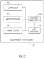
- FIG 2 is a block diagram of a pressure calibrator 70 in accordance with at least one embodiment of the present disclosure.
- the pressure calibrator 70 includes a pressure transducer 10a, such as the Bourdon tube pressure transducer 10 of Figure 1A-1C , a microprocessor 72, a controller 74, a user interface 76, and a power source 78.
- the Bourdon tube pressure transducer 10 is electrically coupled to the microprocessor 72.
- conductive wires may be coupled to the first and/or second end plates 32, 34 of the crystalline sensor 30 and to the microprocessor 72.
- Between the microprocessor 72 and the Bourdon tube pressure transducer 10 may be an amplifier to amplify the signals being provided from the Bourdon tube pressure transducer 10 to the microprocessor 72, as is well known in the art.
- the microprocessor 72 includes suitable logic to receive signals from the Bourdon tube pressure transducer 10, generate pressure values associated with the resonant frequencies of the crystalline sensor 30 of the pressure transducer 10, and provide the pressure values to the user interface 76.
- the microprocessor 72 may further include suitable logic to store the pressure values or use additional information, such as temperature, to modify the output signal, as is well known in the art.
- the pressure calibrator 70 includes a separate memory for storing the pressure values.
- the user interface 76 is coupled to the controller 74 and the microprocessor 72, and may be further coupled to the pressure transducer 10a.
- the user interface 76 may include a display, keyboard, knobs and buttons that allow a user to interact with the microprocessor 72 and the controller 74.
- a display of the user interface 76 may display the pressure generated by the microprocessor 72.
- the controller 74 is electrically coupled to the microprocessor 72, the pressure transducer 10a, the user interface 76, and the power source 78.
- the controller 74 includes suitable control for causing valves within the calibration instrument 70 to open and close, such as, for example, supply valves and exhaust valves.
- the controller 74 may open and close the valves in response to receiving signals from the user interface.
- the controller 74 and the microprocessor 72 are a single component.
- the power source 78 which can be a battery or a plug for coupling to a main power supply, provides power for operating the calibration instrument.
- a pressure transducer including a flexible member made of amorphous quartz and a support structure coupled to the flexible member.
- the flexible member is configured to move in response to pressure changes.
- the pressure transducer further includes a crystalline quartz sensor having a first end coupled to the flexible member and a second end coupled to the support structure. The first and second ends of the crystalline quartz sensor are molecularly bonded to the flexible member and the support structure, respectively.
- the crystalline quartz sensor is configured to detect a force associated with movement of the flexible member.
- the crystalline sensor 30 may be coupled directly to the closed end 18 of the tube 14 without a filament member 40 therebetween.
- the Bourdon tube pressure transducer 10 has a filament member 40 between the second end plate 34 and the support structure 20.
- the Bourdon tube pressure transducer may include filament members 40 at both ends or either one of the ends of the crystalline sensor 30.
- FIG 3 is a schematic illustration of a pressure stabilizing system 80 that includes a Bourdon tube pressure transducer 10a in accordance with at least one embodiment.
- the Bourdon tube pressure transducer 10a is substantially similar in structure and function to the Bourdon tube pressure transducer 10 of Figure 1 except that the second end plate of the crystalline sensor 30 is also coupled to the support structure by a filament member 40 and the support structure has a different orientation.
- the support structure 20a of Figure 3 extends in the same direction as the open end 16 of the tube 14 and has an opening 24a at an end thereof.
- the pressure stabilizing system 80 is configured to adjust for changes in pressure in the external environment to which the Bourdon tube pressure transducer 10a may be exposed.
- the pressure stabilizing system 80 is able to accommodate for the changes in external pressure without affecting stress being applied to the Bourdon tube pressure transducer 10a.
- the pressure stabilizing system 80 is able to vary the volume inside the pressure stabilizing system 80.
- the pressure stabilizing system 80 includes a body 82 having an inner cavity 84 that is sealed from an external environment.
- the Bourdon tube mechanism 12 and the crystalline sensor 30 are located in the cavity 84 of the body 82, while the support structure 20a of the Bourdon tube pressure transducer 10a extends from the cavity 84 and has an opening 24a to be placed in fluid communication with an environment or device to undergo testing.
- the body 82 places the Bourdon tube mechanism 12 and the crystalline sensor 30 in a controllable environment, protecting them from humidity and particles, which can affect the accuracy of Bourdon tube's measurements.
- the cavity 84 has an internal pressure P 1 .
- the opening 24a of the support structure 20a is in fluid communication with an environment to be placed under test, which is referred to as a test pressure P test .
- a bellows 86 coupled to the body 82. Inside the bellows 86 is an inner portion 88 that is sealed from the cavity 84. The inner portion 88 is in fluid communication with the environment that is external to the pressure stabilizing system 80.
- the bellows 86 varies the volume in the cavity 84 by expanding and contracting in response to changes in pressure in the external environment and in the inner portion 88. In particular, the bellows 86 expands and contracts by moving in the directions of the arrow like an accordion to equalize the pressure P 1 in the cavity 84 with a pressure P 2 in the inner portion 88 of the bellows 86.
- the inner portion 88 of the bellows 86 is in fluid communication with the external environment by an opening 90 in the body 82 and has a pressure P 2 , while inside the cavity 84 of the pressure stabilizing system 80, an outer portion of the bellows 86 is exposed to pressure P 1 .
- the pressure stabilizing system 80 when the pressure stabilizing system 80 is moved from a first external environment at a first pressure to a second external environment at a second, higher pressure, the bellows 86 expands, thereby moving toward the Bourdon tube pressure transducer 10a. That is, when pressure P 2 increases, the bellows 86 expands. The bellows 86 expands until the forces acting on the interior and exterior of the bellows 86 by pressures P 2 and P 1 , respectively, equalize.
- the bellows 86 contracts, thereby moving away from the Bourdon tube pressure transducer 10a. That is, when pressure P 2 decreases, the bellows 86 contracts. The bellows 86 contracts until the forces acting on the interior and exterior of the bellows 86 by pressures P 2 and P 1 , respectively, equalize.
- the bellows 86 may be made from any material that suitably equalizes the pressure P 2 inside the bellows 86 with the pressure P 1 inside the cavity 84.
- the bellows 86 is a plastic material such as a resin, which in one embodiment is polyethylene.
- the pressure stabilizing system 80 includes a screen 92 that prevents the bellows 86 from overexpanding and touching the Bourdon tube pressure transducer 10a.
- the screen 92 has openings so that the cavity 84 of the body 82 is at the same pressure P 1 throughout the cavity 84.
- the pressure stabilizing system may include the Bourdon tube pressure transducer 10 of Figure 1 in another embodiment.
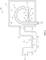
- Figure 4 is directed to another pressure stabilizing system 80a in accordance with another embodiment.
- the pressure stabilizing system 80a is substantially the same in structure and function as the pressure stabilizing system 80 of Figure 3 except that the pressure stabilizing system 80a of Figure 4 uses a different mechanism for stabilizing the pressure.
- the pressure stabilizing system 80a of Figure 4 utilizes a fluidic system 94 to equalize the pressure P 1 in the cavity 84 of the body 82 with the pressure P 2 in the environment external to the pressure stabilizing system 80a.
- the fluidic system 94 includes a tube 95 having a first end that is coupled to and in fluid communication with the cavity 84 of the body 82 housing the Bourdon tube pressure transducer 10a. A second end of the tube 95 is in fluid communication with the external environment.
- the tube 95 includes a liquid 96 configured to move within the tube 95 to adjust for changes in pressure P 2 in the external environment.
- the tube 95 has a horizontal portion having a length L.
- the liquid 96 moves to equalize the pressure P 1 in the cavity 84 with the pressure P 2 in the external environment. For instance, as pressure P 2 in the external environment increases, the liquid 96 moves towards the Bourdon tube pressure transducer 10a. Conversely, as the pressure P 2 in the external environment decreases, the liquid 96 moves away from the Bourdon tube pressure transducer 10a.
- the length L of the horizontal portion is of a suitable length such that the fluid 96 can move along the length L for all pressure ranges for which the pressure stabilizing system 80a will be exposed.
- the pressure stabilizing system 80a may include a detection mechanism 98 that is configured to detect when the liquid 96 moves toward either end of the horizontal portion.
- the detection mechanism 98 is electrical contacts in an inner surface of the tube 95 at opposing ends of the horizontal portion.
- the electrical contacts have conductive wires coupling the electrical contacts to an electrical component, such as the microprocessor 72 of Figure 2 .
- the liquid 96 may be any liquid suitable to remain in the tube for operating periods of the pressure stabilizing system 80a.
- the liquid 96 does not readily evaporate in the environment to which it is exposed.
- the liquid 96 has a low vapor pressure such that it does not readily evaporate.
- the liquid is FluorinertTM.
- the liquid 96 is a conductive liquid and upon the liquid 96 moving toward one end of the horizontal portion and coming in contact with the electrical contacts of detection mechanism 98, a signal is generated and communicated to the microprocessor 72, which may send a signal to the user interface 76 of the calibration instrument 70.
- FIG. 5 shows another detection mechanism 98a that may be used in the tube 95 of the pressure stabilizing system 80a of Figure 4 .
- the detection mechanism 98a of Figure 5 performs the same function as the detection mechanism 98 of Figure 4 , that is, to indicate when the liquid 96 in the tube 95 is close to an end of the horizontal portion.
- the detection mechanism 98a is located at an inner surface of the tube 95 and includes a porous material 100 and a switch 102 located proximate the porous material 100.
- the porous material 100 is configured to expand upon contact with the liquid 96. As the porous material 100 expands, the porous material 100 causes the switch 102 to flip to change its state.
- the pressure stabilizing system 80 of Figure 3 and 80a of Figure 4 may be in the calibration instrument 70 of Figure 2 as the pressure transducer 10a.
- the switch 102 is coupled to the microprocessor 72 and communicates this change of state to the microprocessor 72, which may be further communicated to the user interface.
- FIG 6 is a schematic illustration of a membrane pressure transducer 110 in accordance with at least one embodiment.
- Many components, such as the crystalline sensor 30 and the filament member 40, of the membrane pressure transducer 110 are similar in structure and function to the Bourdon tube pressure transducer 10 of Figures 1A and 1B and the Bourdon tube pressure transducer 10a of Figures 3 and 4 , except that the membrane pressure transducer 110 does not include a Bourdon tube mechanism 12. Rather, the membrane pressure transducer 110 includes a flexible membrane 112 that flexes in response to changes in pressure.
- the membrane pressure transducer 110 includes a tube 14a having an inlet for being placed in fluid communication with a device to undergo testing.
- the tube 14a opens to an inner cavity that is formed, in part, by the flexible membrane 112.
- a crystalline sensor 30 is coupled to the flexible membrane 112 to sense the movement of the membrane.
- a first end plate 32 of the crystalline sensor 30 is coupled to the flexible membrane 112 and a second end plate 34 is coupled to a support structure 116.
- a first end of the support structure 116 is coupled to the second end plate 34 of the crystalline sensor 30 by a filament element 40 and a second end of the support structure 116 is coupled to the tube 14a.
- a filament element 40 is located between the first end plate 32 and the flexible membrane 40.
- Various components of the membrane pressure transducer 110 are made from amorphous quartz.
- the tube 14a, the flexible membrane 112, the support structure 116, and the filament elements may be made of amorphous quartz that are coupled together using the methods discussed above.
- the flexible member 112 is located inside a cavity 84 of a body 82.
- the cavity 84 has a pressure P 2 .
- the open end of the tube 14a is placed in fluid communication with an environment or device to undergo testing, which has a pressure P test .
- the membrane pressure transducer 110 may be the pressure transducer 10a of the calibration instrument 70 of Figure 2 .
- Examples provide a pressure transducer comprising: a Bourdon tube mechanism of amorphous quartz having a tube with a closed end and an open end, the open end of the tube being configured to be placed in fluid communication with a fluid and to receive the fluid into the tube, the closed end of the tube being configured to flex in response to a change in pressure in the tube; a support structure of amorphous quartz coupled to the Bourdon tube mechanism without an adhesive material; and a crystalline quartz sensor coupled between the closed end of the tube and the support structure, wherein the crystalline quartz sensor is in tension or compression for the operating range of the pressure transducer.
- the crystalline quartz sensor is coupled between the closed end of the tube and the support structure without an adhesive material.
- pressure transducer further comprises one or more filaments, each filament coupled to an end of the crystalline quartz sensor, the filament having a dimension that is 0.5% to 15% less than a dimension of the tube.
- the filament is made of amorphous quartz.
- the support structure includes a channel that has a first end that is in fluid communication with the open end of the Bourdon tube mechanism and a second end that is open and configured to receive the fluid.
- the crystalline quartz sensor is in tension when in the Bourdon tube mechanism is in a neutral position.
- the crystalline quartz sensor is a resonant sensor.
- Examples provide a pressure transducer comprising: a flexible member made of amorphous quartz, the flexible member being configured to move in response to pressure changes; a support structure coupled to the flexible member; and a crystalline quartz sensor having a first end coupled to the flexible member and a second end coupled to the support structure, wherein the first and second ends of the crystalline quartz sensor are molecularly bonded to the flexible member and the support structure, respectively, and the crystalline quartz sensor is configured to detect a force associated with movement of the flexible member.
- the flexible member is one of a Bourdon tube mechanism that includes a tube with an open end to receive a fluid and a closed end and a flexible diaphragm.
- the flexible member is a Bourdon tube mechanism that is C-shaped.
- the first end of the crystalline quartz sensor is coupled to the closed end of the tube by a filament made of amorphous quartz, wherein the filament has a diameter that is less than a diameter of the tube.
- the filament has a cross-sectional area that is less than one hundred times a cross-sectional area of the tube.
- the crystalline quartz sensor remains in tension or compression for the operating range of the pressure transducer.
- the crystalline quartz is in a pre-tensioned position when exposed to absolute atmospheric pressure.
- Examples provide a calibration instrument comprising: a Bourdon tube made of amorphous quartz and having a closed end and an open end, the open end configured to receive a fluid, the closed end configured to flex in response to a change in pressure in the Bourdon tube; and a crystalline quartz sensor coupled to the closed end of the Bourdon tube, wherein the crystalline quartz sensor is in tension or compression for an operating range of the pressure transducer; and a microprocessor coupled to the pressure transducer.
- the crystalline quartz sensor is molecularly coupled to the closed end of the Bourdon tube without adhesive material therebetween.
- the crystalline quartz sensor remains in tension or compression for the entire operating range of the pressure transducer.
- the first end of the crystalline quartz sensor is coupled to the closed end of the Bourdon tube by a filament, the filament having a cross-sectional area that is less than a cross-sectional area of the Bourdon tube.
- the filament is made of amorphous quartz.
- the crystalline quartz sensor has a longitudinal axis that is parallel with a tangent of a curving motion of the closed end of the Bourdon tube.
- the Bourdon tube is located in a cavity of a pressure stabilizing system, and the pressure stabilizing system is configured to equalizes a first pressure in the cavity with a second pressure in an environment external to the pressure stabilizing system.
- the pressure stabilizing system includes bellows or a fluidic system to equalize the first pressure in the cavity with the second pressure in the environment external to the pressure stabilizing system.
Landscapes
- Physics & Mathematics (AREA)
- General Physics & Mathematics (AREA)
- Electromagnetism (AREA)
- Measuring Fluid Pressure (AREA)
Abstract
Description
- Embodiments are directed to pressure transducers and calibration instruments.
- Generally described, Bourdon tubes are tubes that flex radially, by coiling and uncoiling, in response to pressure changes between the tube and it surrounding environment. A sensor, such as a resonant sensor, may be attached to a closed end of the tube so that as the tube flexes, the movement imparts a force on the resonant sensor. The frequency at which the resonant sensor resonates due to the force is indicative of the pressure in the tube.
- Typically, Bourdon tubes are made from a metal material. The metal material, however, has been shown to cause hysteresis, a phenomenon that can affect the true measurement of the Bourdon tube. In particular, hysteresis occurs due to metal Bourdon tubes retaining some energy between measurements. For instance, the metal Bourdon tube may retain deformations for a period of time after a measurement has been obtained. Thus, during a subsequent measurement that occurs during the period of time in which the Bourdon tube is deformed, the deformity affects the measurement, thereby contributing error to the subsequent measurement. Although metal is described as causing hysteresis, adhesive materials, such as epoxy, which bond the metal Bourdon tube to various components within a Bourdon tube pressure transducer, can also cause hysteresis, as can stress in the mounting or structural materials throughout the device.
- One or more embodiments are directed to a pressure transducer comprising a flexible member made of amorphous quartz and a crystalline quartz sensor that are coupled together without an adhesive material. Rather, the amorphous quartz of the flexible member and the crystalline quartz sensor are coupled together at the molecular level. The bonding may be encouraged by the application of one or more of heat, water, solvents, and additives, such as salt, at the joining surfaces to encourage intermolecular bonding therebetween.
- The flexible member is a Bourdon tube mechanism in at least one embodiment. In at least one embodiment, the crystalline quartz sensor is prestressed in either compression or tension when, for instance, the pressure transducer is exposed to atmospheric pressure. In that regard, the quartz sensor may be able to self-orient and substantially restrict to remain within the linear motion of the flexible member. In some embodiments, the crystalline quartz sensor remains in compression or tension during the entire operating range.
- One embodiment of the present disclosure is directed to a pressure transducer comprising a Bourdon tube mechanism of amorphous quartz having a tube with a closed end and an open end. The open end of the tube is configured to be placed in fluid communication with a fluid and to receive the fluid into the tube. The closed end of the tube is configured to flex in response to a change in pressure in the tube. The pressure transducer further includes a support structure of amorphous quartz coupled to the Bourdon tube mechanism without an adhesive material. The pressure transducer further includes a crystalline quartz sensor coupled between the closed end of the tube and the support structure. The crystalline quartz sensor is in tension or compression for the operating range of the pressure transducer.
- Another embodiment of the present disclosure is directed to a pressure transducer comprising a flexible member made of amorphous quartz. The flexible member is configured to move in response to pressure changes. The pressure transducer further includes a support structure coupled to the flexible member and a crystalline quartz sensor. The crystalline quartz sensor has a first end coupled to the flexible member and a second end coupled to the support structure. The first and second ends of the crystalline quartz sensor are molecularly bonded to the flexible member and the support structure, respectively. The crystalline quartz sensor is configured to detect a force associated with movement of the flexible member.
- Another embodiment is directed to a calibration instrument comprising a pressure transducer and a microprocessor coupled to the pressure transducer. The pressure transducer includes a Bourdon tube made of amorphous quartz and having a closed end and an open end. The open end of the Bourdon tube is configured to receive a fluid, and the closed end is configured to flex in response to a change in pressure in the Bourdon tube. The pressure transducer further includes a crystalline quartz sensor coupled to the closed end of the Bourdon tube. The crystalline quartz sensor is in tension or compression for an operating range of the pressure transducer.
-
-
Figures 1A is a schematic cross-section view of a Bourdon tube pressure transducer in a first position in accordance with one embodiment; -
Figures 1B is a schematic cross-section view of the Bourdon tube pressure transducer ofFigure 1A in a second position; -
Figures 1C is a schematic partial cross-section view of the Bourdon tube pressure transducer ofFigure 1 B; -
Figure 2 is a block diagram of a calibration instrument that includes a pressure transducer in accordance with one embodiment; -
Figure 3 is a schematic illustration of a pressure stabilizing system that includes a Bourdon tube pressure transducer in accordance with one embodiment; -
Figure 4 is a schematic illustration of a pressure stabilizing system that includes a Bourdon tube pressure transducer in accordance with another embodiment; -
Figure 5 is a schematic illustration of detection mechanism for use in the pressure stabilizing system ofFigure 4 in accordance with another embodiment; and -
Figure 6 is a schematic illustration of a membrane pressure transducer in accordance with one embodiment. - As will be explained in detail below, the pressure transducers described herein have many components being made of amorphous quartz, for example fused silica or fused quartz, such as silicon dioxide (SiO2), and a resonant sensor made of crystalline quartz. In one or more embodiments, various amorphous quartz components and the crystalline quartz are bonded together without the use of an adhesive material, such as epoxy, thereby reducing the likelihood of hysteresis occurring during the operation of the pressure transducer. Rather, bonding between the components occurs at the molecular level. The bonding includes the application of one or more of heat, water, solvents, and additives, such as salt, to the joining surfaces to encourage intermolecular bonding therebetween, but does not include an adhesive material. For instance, in one embodiment salt silica is used as a bonding agent to create semi-homogeneous bonding between fused silica and the crystalline silica resonant sensor. The salt silica is also referred to as waterglass, which is a salt silicate solution that devolves into glass when it becomes anhydrous. Salt silica may also refer to sodium silicate, potassium silicate or other metal salts.
-
Figures 1A-1C are directed to a Bourdontube pressure transducer 10 in accordance with at least one embodiment of the disclosure. InFigure 1A , the Bourdontube pressure transducer 10 is in a first position, and inFigure 1B , the Bourdontube pressure transducer 10 is in a second position.Figure 1C is a cross-section view of a portion of the Bourdontube pressure transducer 10 as indicated inFigure 1B . - The Bourdon
tube pressure transducer 10 includes a Bourdontube mechanism 12 that includes anamorphous quartz tube 14 curved into a C-shape; however, the tube may be in other shapes, such as U-shaped, circular, and helical. Thetube 14 is a hollow tube that is open at anopen end 16 and closed at an opposite, closedend 18. The tube is made of an amorphous quartz, which is an elastic material that flexes in response to pressure being applied thereto, while at the same time is a sufficiently rigid to allow for a variety of different pressure ranges depending on the thickness and shape of thetube 14. Thus, as pressure inside of the tube changes, the closedend 18 moves, such as by flexing upward, relative to theopen end 16. - The
open end 16 of thetube 14 is coupled to asupport structure 20. Thesupport structure 20 has achannel 22 having a first opening that is in fluid communication withtube 14 at theopen end 16 of thetube 14 and asecond opening 24 that places thechannel 22, and thus thetube 14, in fluid communication with an environment external to the Bourdontube pressure transducer 10. During operation, thesecond opening 24 of thechannel 22 is configured to receive a fluid, such as a gas or liquid, to be tested and the fluid travels through thechannel 22 to thetube 14. - The
support structure 20 is also made of amorphous quartz. Thesupport structure 20 is coupled to thetube 14 at theopen end 16 of thetube 14. Thesupport structure 20 and thetube 14 are coupled together without the use of an adhesive material. Rather, the amorphous quartz of thesupport structure 20 and the amorphous quartz of thetube 14 are coupled together by molecular bonding. As mentioned above, the bonding between thetube 14 and thesupport structure 20 may be encouraged by one or more of heat, water, solvents, and additives, such as salt. - The Bourdon
tube pressure transducer 10 further includes acrystalline sensor 30. Thecrystalline sensor 30 has afirst end plate 32 coupled to theBourdon tube mechanism 12 at theclosed end 18 of thetube 14, the details of which will be discussed in more detail later. Thecrystalline sensor 30 has asecond end plate 34 coupled to thesupport structure 20. Thesecond end plate 34 is coupled to thesupport structure 20 without an adhesive material. Rather, the crystalline material of thesecond end plate 34 molecularly bonds with the amorphous quartz of thesupport structure 20. The intermolecular bonding may be encouraged by one or more of heat, water, solvents, and additives, such as salt, at the joining surfaces. - The
crystalline sensor 30 is configured to be stretched in response to thesecond end 18 of thetube 14 flexing upward relative to theopen end 16 of thetube 14. Thecrystalline sensor 30 is a resonant force sensor that has natural resonant frequencies that are a function of the force being applied thereto. In particular, between the first andsecond end plates crystalline sensor 30 are tworesonant beams 36 that are configured to resonate in response to a force being applied to thecrystalline sensor 30. The frequency at which theresonant beams 36 resonate is dependent on the force being applied to thecrystalline sensor 30. In that regard, theresonant beams 36 are configured to resonate within a range of frequencies. For instance, theresonant beams 36 are configured to resonate at a first natural resonant frequency when theclosed end 18 of thetube 14 of theBourdon tube mechanism 12 is in the first position shown inFigure 1A , and resonate at a second natural resonant frequency when theclosed end 18 of thetube 14 of theBourdon tube mechanism 12 is in the second position shown inFigure 1B . In the second position, the pressure in thetube 14 is greater than the pressure in thetube 14 in the first position. It is to be appreciated that theresonant beams 36 may resonate under tension and/or compression. - The frequency at which the
resonant beams 36 of thecrystalline sensor 30 resonate not only depends on force but also depends on the temperature of thecrystalline sensor 30. That is, measurements of theresonant beams 36 can also be affected by heat transferred to thecrystalline sensor 30. For instance, theBourdon tube mechanism 12 may be exposed to fluids of varying temperatures and transfer those changes to thecrystalline sensor 30, thereby affecting the true measurement. Thus, to thermally isolate thecrystalline sensor 30 from thebourdon tube mechanism 12, there is provided afilament member 40 between thefirst end plate 32 of thecrystalline sensor 30 and theclosed end 18 of theBourdon tube mechanism 12. - As best shown in the cross-section view of
Figure 1C , thefilament member 40 includes first and secondplanar elements filament 46. The firstplanar element 42 is coupled to a surface of thefirst end plate 32 of thecrystalline sensor 30 and the secondplanar element 44 that is coupled to theclosed end 18 of thetube 14. The first and secondplanar elements first end plate 32 of thecrystalline sensor 30 andclosed end 18 of thetube 14, respectively, without an adhesive material. As mentioned above, the bonding process may include the addition of one or more of heat, water, solvents, and additives, such as salt, at the joining surfaces. - The
filament 46 has a reduced cross-sectional area relative to a cross-sectional area of the Bourdon tube mechanism, such as relative to theclosed end 18 of thetube 14. For instance, thefilament 46 may have a diameter that is 0.5% to 15% less than a diameter of thetube 14. - Thus, by providing a
filament 46 with a reduced cross-sectional area as described above between theclosed end 18 of thetube 14 and thefirst end plate 32 of thecrystalline sensor 30, changes in temperature introduced to thetube 14 during operation are not transferred to thecrystalline sensor 30 or are at least substantially reduced. In that regard, the accuracy and/or precision of thecrystalline sensor 30 is improved. - The
Bourdon tube mechanism 12, when not in operation, is at rest in a neutral position, which in at least one embodiment is the position shown inFigure 1A . In operation, theopening 24 of thesupport structure 20 is placed in fluid communication with a fluid, such as a gas or a liquid, for determining a pressure thereof. When, for example, fluid enters thetube 14 and increases the pressure therein, theclosed end 18 of thetube 14 begins to uncoil or straighten out, such as to the position shown inFigure 1B , thereby placing thecrystalline sensor 30 under tension or under further tension. The tensionedcrystalline sensor 30 resonates at a resonant frequency that is proportional to the pressure. Conversely, as pressure in theBourdon tube mechanism 12 decreases, theclosed end 18 of theamorphous quartz tube 14 curls or moves downward, such as to the position shown inFigure 1A . The geometry of thetube 14 may be adjusted depending on desired range of forces to be measured by thecrystalline sensor 30. - In one embodiment, the
crystalline sensor 30 and thefilament member 40 are arranged linearly with each other along a line of movement or parallel to the line of movement of theclosed end 18 of thetube 14. In general, theBourdon tube mechanism 12 moves substantially radially. That is, theclosed end 18 of thetube 14 uncoils in a motion that is radial to a fixed point of theBourdon tube mechanism 12, such as theopen end 16 of thetube 14. Thus, the line of movement is defined as a line that is tangent to the curving motion of theclosed end 18 of thetube 14. By aligning a longitudinal axis of thecrystalline sensor 30 and a longitudinal axis of the filament to be parallel with the tangent of the curving motion of theclosed end 18 of thetube 14, measurement losses are reduced. That is, theresonant beams 36 are stretched or compressed uniaxially, rather than placing a moment force on theresonant beams 36, thereby improving the accuracy and precision of the measurement. - In one embodiment, the
crystalline sensor 30 is tensioned across the entire operating range of the Bourdontube pressure transducer 10. In particular, thecrystalline sensor 30 is pre-tensioned, such that when theBourdon tube mechanism 12 is in its neutral position, thecrystalline sensor 30 is already under tension at atmospheric pressure, resulting insensor 30 remaining under tension at a lowest pressure, such as a vacuum, for a particular application, throughout the entire range of the pressure sensor to a highest pressure for the particular application. For instance, in this embodiment the position of the Bourdontube pressure transducer 10 ofFigure 1B may be the initial, neutral position. When fluid exits thetube 14, decreasing the pressure therein, theBourdon tube mechanism 12 begins to coil, thereby reducing the tensioning on thecrystalline sensor 30, which places theBourdon tube mechanism 12 in the position shown inFigure 1A . Conversely, in reference toFigure 1B being the initial position and fluid entering the tube increases the pressure therein, theBourdon tube mechanism 12 continues to uncoil or straighten out farther than the position shown inFigure 1B , thereby placing thecrystalline sensor 30 under further tension. - By maintaining the
crystalline sensor 30 in tension over the entire operating range, translation of pressure into an output signal can be more linear. It is to be appreciated that when thecrystalline sensor 30 transitions between compression and tension, thecrystalline sensor 30 may include some out-of-plane movement that adversely affects the true measurement value. That is, the movement of thecrystalline sensor 30 has a first vector component that is parallel to the longitudinal axis of thecrystalline sensor 30 and has a second, smaller vector component that is perpendicular to the longitudinal axis of thecrystalline sensor 30. Although the second vector component will be substantially smaller than the first vector component, the second vector component will introduce an error into the output of the sensor. Thus, by maintaining thecrystalline sensor 30 in tension over the entire operating range of the Bourdontube pressure transducer 10, the accuracy and precision of the Bourdontube pressure transducer 10 is improved. - Although the above embodiment described the
crystalline sensor 30 being in tension for the entire operating range, it will be apparent to the person of ordinary skill in the art that the pre-stressing of thecrystalline sensor 30 could apply to compression as well. - As mentioned above, the
Bourdon tube mechanism 12, thesupport structure 20, and thefilament member 40 are all made from amorphous quartz. In one embodiment, theBourdon tube mechanism 12, thesupport structure 20, and thefilament member 40 are made from the same type of amorphous quartz, such as fused silica or fused quartz, and are fused together without the use of a non-glass adhesive material. By making these components of the same material any warpage that might occur during operation due to materials having differing coefficients of thermal expansion (CTE) is eliminated. Furthermore, creep, which is known to occur in adhesive materials such as epoxy, is reduced or eliminated. -
Figure 2 is a block diagram of apressure calibrator 70 in accordance with at least one embodiment of the present disclosure. Thepressure calibrator 70 includes apressure transducer 10a, such as the Bourdontube pressure transducer 10 ofFigure 1A-1C , amicroprocessor 72, acontroller 74, auser interface 76, and apower source 78. The Bourdontube pressure transducer 10 is electrically coupled to themicroprocessor 72. In particular, conductive wires may be coupled to the first and/orsecond end plates crystalline sensor 30 and to themicroprocessor 72. Between themicroprocessor 72 and the Bourdontube pressure transducer 10 may be an amplifier to amplify the signals being provided from the Bourdontube pressure transducer 10 to themicroprocessor 72, as is well known in the art. - The
microprocessor 72 includes suitable logic to receive signals from the Bourdontube pressure transducer 10, generate pressure values associated with the resonant frequencies of thecrystalline sensor 30 of thepressure transducer 10, and provide the pressure values to theuser interface 76. Themicroprocessor 72 may further include suitable logic to store the pressure values or use additional information, such as temperature, to modify the output signal, as is well known in the art. Alternatively, thepressure calibrator 70 includes a separate memory for storing the pressure values. - The
user interface 76 is coupled to thecontroller 74 and themicroprocessor 72, and may be further coupled to thepressure transducer 10a. Theuser interface 76 may include a display, keyboard, knobs and buttons that allow a user to interact with themicroprocessor 72 and thecontroller 74. For instance, a display of theuser interface 76 may display the pressure generated by themicroprocessor 72. - The
controller 74 is electrically coupled to themicroprocessor 72, thepressure transducer 10a, theuser interface 76, and thepower source 78. Thecontroller 74 includes suitable control for causing valves within thecalibration instrument 70 to open and close, such as, for example, supply valves and exhaust valves. Thecontroller 74 may open and close the valves in response to receiving signals from the user interface. In one embodiment, thecontroller 74 and themicroprocessor 72 are a single component. - The
power source 78, which can be a battery or a plug for coupling to a main power supply, provides power for operating the calibration instrument. - While the foregoing description illustrates and describes a Bourdon tube pressure transducer, it should be understood that the pressure transducer may be of a type other than Bourdon tube. For instance, in one embodiment, there is provided a pressure transducer including a flexible member made of amorphous quartz and a support structure coupled to the flexible member. The flexible member is configured to move in response to pressure changes. The pressure transducer further includes a crystalline quartz sensor having a first end coupled to the flexible member and a second end coupled to the support structure. The first and second ends of the crystalline quartz sensor are molecularly bonded to the flexible member and the support structure, respectively. The crystalline quartz sensor is configured to detect a force associated with movement of the flexible member.
- Furthermore, although not shown in the illustrated embodiment, the
crystalline sensor 30 may be coupled directly to theclosed end 18 of thetube 14 without afilament member 40 therebetween. In other embodiments, the Bourdontube pressure transducer 10 has afilament member 40 between thesecond end plate 34 and thesupport structure 20. In that regard, the Bourdon tube pressure transducer may includefilament members 40 at both ends or either one of the ends of thecrystalline sensor 30. -
Figure 3 is a schematic illustration of apressure stabilizing system 80 that includes a Bourdontube pressure transducer 10a in accordance with at least one embodiment. The Bourdontube pressure transducer 10a is substantially similar in structure and function to the Bourdontube pressure transducer 10 ofFigure 1 except that the second end plate of thecrystalline sensor 30 is also coupled to the support structure by afilament member 40 and the support structure has a different orientation. In particular, thesupport structure 20a ofFigure 3 extends in the same direction as theopen end 16 of thetube 14 and has anopening 24a at an end thereof. - As will be explained below, the
pressure stabilizing system 80 is configured to adjust for changes in pressure in the external environment to which the Bourdontube pressure transducer 10a may be exposed. In that regard, thepressure stabilizing system 80 is able to accommodate for the changes in external pressure without affecting stress being applied to the Bourdontube pressure transducer 10a. In particular, thepressure stabilizing system 80 is able to vary the volume inside thepressure stabilizing system 80. - The
pressure stabilizing system 80 includes abody 82 having aninner cavity 84 that is sealed from an external environment. TheBourdon tube mechanism 12 and thecrystalline sensor 30 are located in thecavity 84 of thebody 82, while thesupport structure 20a of the Bourdontube pressure transducer 10a extends from thecavity 84 and has anopening 24a to be placed in fluid communication with an environment or device to undergo testing. - The
body 82 places theBourdon tube mechanism 12 and thecrystalline sensor 30 in a controllable environment, protecting them from humidity and particles, which can affect the accuracy of Bourdon tube's measurements. Thecavity 84 has an internal pressure P1. Theopening 24a of thesupport structure 20a is in fluid communication with an environment to be placed under test, which is referred to as a test pressure Ptest. - Inside the
cavity 84 is a bellows 86 coupled to thebody 82. Inside thebellows 86 is aninner portion 88 that is sealed from thecavity 84. Theinner portion 88 is in fluid communication with the environment that is external to thepressure stabilizing system 80. The bellows 86 varies the volume in thecavity 84 by expanding and contracting in response to changes in pressure in the external environment and in theinner portion 88. In particular, thebellows 86 expands and contracts by moving in the directions of the arrow like an accordion to equalize the pressure P1 in thecavity 84 with a pressure P2 in theinner portion 88 of thebellows 86. - As mentioned above, the
inner portion 88 of thebellows 86 is in fluid communication with the external environment by anopening 90 in thebody 82 and has a pressure P2, while inside thecavity 84 of thepressure stabilizing system 80, an outer portion of thebellows 86 is exposed to pressure P1. In operation, when thepressure stabilizing system 80 is moved from a first external environment at a first pressure to a second external environment at a second, higher pressure, thebellows 86 expands, thereby moving toward the Bourdontube pressure transducer 10a. That is, when pressure P2 increases, thebellows 86 expands. The bellows 86 expands until the forces acting on the interior and exterior of thebellows 86 by pressures P2 and P1, respectively, equalize. - Conversely, when the
pressure stabilizing system 80 is moved from a first external environment at a first pressure to a second external environment to a second, lower pressure, thebellows 86 contracts, thereby moving away from the Bourdontube pressure transducer 10a. That is, when pressure P2 decreases, thebellows 86 contracts. The bellows 86 contracts until the forces acting on the interior and exterior of thebellows 86 by pressures P2 and P1, respectively, equalize. - The bellows 86 may be made from any material that suitably equalizes the pressure P2 inside the
bellows 86 with the pressure P1 inside thecavity 84. In at least one embodiment, thebellows 86 is a plastic material such as a resin, which in one embodiment is polyethylene. - In the illustrated embodiment, the
pressure stabilizing system 80 includes ascreen 92 that prevents thebellows 86 from overexpanding and touching the Bourdontube pressure transducer 10a. Thescreen 92 has openings so that thecavity 84 of thebody 82 is at the same pressure P1 throughout thecavity 84. - It is to be appreciated that in another embodiment the pressure stabilizing system may include the Bourdon
tube pressure transducer 10 ofFigure 1 in another embodiment. -
Figure 4 is directed to anotherpressure stabilizing system 80a in accordance with another embodiment. Thepressure stabilizing system 80a is substantially the same in structure and function as thepressure stabilizing system 80 ofFigure 3 except that thepressure stabilizing system 80a ofFigure 4 uses a different mechanism for stabilizing the pressure. Thepressure stabilizing system 80a ofFigure 4 utilizes afluidic system 94 to equalize the pressure P1 in thecavity 84 of thebody 82 with the pressure P2 in the environment external to thepressure stabilizing system 80a. - As shown in
Figure 4 , thefluidic system 94 includes atube 95 having a first end that is coupled to and in fluid communication with thecavity 84 of thebody 82 housing the Bourdontube pressure transducer 10a. A second end of thetube 95 is in fluid communication with the external environment. Thetube 95 includes a liquid 96 configured to move within thetube 95 to adjust for changes in pressure P2 in the external environment. - The
tube 95 has a horizontal portion having a length L. In the horizontal portion the liquid 96 moves to equalize the pressure P1 in thecavity 84 with the pressure P2 in the external environment. For instance, as pressure P2 in the external environment increases, the liquid 96 moves towards the Bourdontube pressure transducer 10a. Conversely, as the pressure P2 in the external environment decreases, the liquid 96 moves away from the Bourdontube pressure transducer 10a. The length L of the horizontal portion is of a suitable length such that the fluid 96 can move along the length L for all pressure ranges for which thepressure stabilizing system 80a will be exposed. - The
pressure stabilizing system 80a may include adetection mechanism 98 that is configured to detect when the liquid 96 moves toward either end of the horizontal portion. In the illustrated embodiment, thedetection mechanism 98 is electrical contacts in an inner surface of thetube 95 at opposing ends of the horizontal portion. Although not shown, the electrical contacts have conductive wires coupling the electrical contacts to an electrical component, such as themicroprocessor 72 ofFigure 2 . - The liquid 96 may be any liquid suitable to remain in the tube for operating periods of the
pressure stabilizing system 80a. Preferably, the liquid 96 does not readily evaporate in the environment to which it is exposed. Thus, in some embodiments the liquid 96 has a low vapor pressure such that it does not readily evaporate. In one embodiment, the liquid is Fluorinert™. - In this embodiment, the liquid 96 is a conductive liquid and upon the liquid 96 moving toward one end of the horizontal portion and coming in contact with the electrical contacts of
detection mechanism 98, a signal is generated and communicated to themicroprocessor 72, which may send a signal to theuser interface 76 of thecalibration instrument 70. -
Figure 5 shows anotherdetection mechanism 98a that may be used in thetube 95 of thepressure stabilizing system 80a ofFigure 4 . Thedetection mechanism 98a ofFigure 5 performs the same function as thedetection mechanism 98 ofFigure 4 , that is, to indicate when the liquid 96 in thetube 95 is close to an end of the horizontal portion. Thedetection mechanism 98a is located at an inner surface of thetube 95 and includes aporous material 100 and aswitch 102 located proximate theporous material 100. Theporous material 100 is configured to expand upon contact with the liquid 96. As theporous material 100 expands, theporous material 100 causes theswitch 102 to flip to change its state. - The
pressure stabilizing system 80 ofFigure 3 and 80a ofFigure 4 may be in thecalibration instrument 70 ofFigure 2 as thepressure transducer 10a. In one embodiment, theswitch 102 is coupled to themicroprocessor 72 and communicates this change of state to themicroprocessor 72, which may be further communicated to the user interface. -
Figure 6 is a schematic illustration of amembrane pressure transducer 110 in accordance with at least one embodiment. Many components, such as thecrystalline sensor 30 and thefilament member 40, of themembrane pressure transducer 110 are similar in structure and function to the Bourdontube pressure transducer 10 ofFigures 1A and1B and the Bourdontube pressure transducer 10a ofFigures 3 and4 , except that themembrane pressure transducer 110 does not include aBourdon tube mechanism 12. Rather, themembrane pressure transducer 110 includes aflexible membrane 112 that flexes in response to changes in pressure. - The
membrane pressure transducer 110 includes atube 14a having an inlet for being placed in fluid communication with a device to undergo testing. Thetube 14a opens to an inner cavity that is formed, in part, by theflexible membrane 112. Acrystalline sensor 30 is coupled to theflexible membrane 112 to sense the movement of the membrane. In particular, afirst end plate 32 of thecrystalline sensor 30 is coupled to theflexible membrane 112 and asecond end plate 34 is coupled to asupport structure 116. In particular, a first end of thesupport structure 116 is coupled to thesecond end plate 34 of thecrystalline sensor 30 by afilament element 40 and a second end of thesupport structure 116 is coupled to thetube 14a. Afilament element 40 is located between thefirst end plate 32 and theflexible membrane 40. Various components of themembrane pressure transducer 110 are made from amorphous quartz. For instance, thetube 14a, theflexible membrane 112, thesupport structure 116, and the filament elements may be made of amorphous quartz that are coupled together using the methods discussed above. - The
flexible member 112 is located inside acavity 84 of abody 82. Thecavity 84 has a pressure P2. The open end of thetube 14a is placed in fluid communication with an environment or device to undergo testing, which has a pressure Ptest. - In operation, when a test pressure Ptest is higher than the pressure P2, the
flexible membrane 112 moves to the right toward thecrystalline sensor 30, thereby causing thecrystalline sensor 30 to be placed under compression. When a test pressure Ptest is less than the pressure P2, theflexible membrane 112 moves to the left, thereby causing thecrystalline sensor 30 to be placed under tension. - The
membrane pressure transducer 110 may be thepressure transducer 10a of thecalibration instrument 70 ofFigure 2 . - Examples provide a pressure transducer comprising: a Bourdon tube mechanism of amorphous quartz having a tube with a closed end and an open end, the open end of the tube being configured to be placed in fluid communication with a fluid and to receive the fluid into the tube, the closed end of the tube being configured to flex in response to a change in pressure in the tube; a support structure of amorphous quartz coupled to the Bourdon tube mechanism without an adhesive material; and a crystalline quartz sensor coupled between the closed end of the tube and the support structure, wherein the crystalline quartz sensor is in tension or compression for the operating range of the pressure transducer.
- In some examples the crystalline quartz sensor is coupled between the closed end of the tube and the support structure without an adhesive material.
- In some examples pressure transducer further comprises one or more filaments, each filament coupled to an end of the crystalline quartz sensor, the filament having a dimension that is 0.5% to 15% less than a dimension of the tube.
- In some examples the filament is made of amorphous quartz.
- In some examples the support structure includes a channel that has a first end that is in fluid communication with the open end of the Bourdon tube mechanism and a second end that is open and configured to receive the fluid.
- In some examples the crystalline quartz sensor is in tension when in the Bourdon tube mechanism is in a neutral position.
- In some examples the crystalline quartz sensor is a resonant sensor.
- Examples provide a pressure transducer comprising: a flexible member made of amorphous quartz, the flexible member being configured to move in response to pressure changes; a support structure coupled to the flexible member; and a crystalline quartz sensor having a first end coupled to the flexible member and a second end coupled to the support structure, wherein the first and second ends of the crystalline quartz sensor are molecularly bonded to the flexible member and the support structure, respectively, and the crystalline quartz sensor is configured to detect a force associated with movement of the flexible member.
- In some examples the flexible member is one of a Bourdon tube mechanism that includes a tube with an open end to receive a fluid and a closed end and a flexible diaphragm.
- In some examples the flexible member is a Bourdon tube mechanism that is C-shaped.
- In some examples the first end of the crystalline quartz sensor is coupled to the closed end of the tube by a filament made of amorphous quartz, wherein the filament has a diameter that is less than a diameter of the tube.
- In some examples the filament has a cross-sectional area that is less than one hundred times a cross-sectional area of the tube.
- In some examples the crystalline quartz sensor remains in tension or compression for the operating range of the pressure transducer.
- In some examples the crystalline quartz is in a pre-tensioned position when exposed to absolute atmospheric pressure.
- Examples provide a calibration instrument comprising: a Bourdon tube made of amorphous quartz and having a closed end and an open end, the open end configured to receive a fluid, the closed end configured to flex in response to a change in pressure in the Bourdon tube; and a crystalline quartz sensor coupled to the closed end of the Bourdon tube, wherein the crystalline quartz sensor is in tension or compression for an operating range of the pressure transducer; and a microprocessor coupled to the pressure transducer.
- In some examples the crystalline quartz sensor is molecularly coupled to the closed end of the Bourdon tube without adhesive material therebetween.
- In some examples the crystalline quartz sensor remains in tension or compression for the entire operating range of the pressure transducer.
- In some examples, the first end of the crystalline quartz sensor is coupled to the closed end of the Bourdon tube by a filament, the filament having a cross-sectional area that is less than a cross-sectional area of the Bourdon tube.
- In some examples the filament is made of amorphous quartz.
- In some examples the crystalline quartz sensor has a longitudinal axis that is parallel with a tangent of a curving motion of the closed end of the Bourdon tube.
- In some examples the Bourdon tube is located in a cavity of a pressure stabilizing system, and the pressure stabilizing system is configured to equalizes a first pressure in the cavity with a second pressure in an environment external to the pressure stabilizing system.
- In some examples, the pressure stabilizing system includes bellows or a fluidic system to equalize the first pressure in the cavity with the second pressure in the environment external to the pressure stabilizing system.
- The various features and embodiments described above can be combined in any manner to provide further embodiments. These and other changes can be made to the embodiments in light of the above-detailed description. In general, in the following claims, the terms used should not be construed to limit the claims to the specific embodiments disclosed in the specification, but should be construed to include all possible embodiments along with the full scope of equivalents to which such claims are entitled. Accordingly, the claims are not limited by the specific embodiments disclosed.
Claims (15)
- A pressure transducer comprising:a Bourdon tube mechanism of amorphous quartz having a tube with a closed end and an open end, the open end of the tube being configured to be placed in fluid communication with a fluid and to receive the fluid into the tube, the closed end of the tube being configured to flex in response to a change in pressure in the tube;a support structure of amorphous quartz coupled to the Bourdon tube mechanism without an adhesive material; anda crystalline quartz sensor coupled between the closed end of the tube and the support structure, wherein the crystalline quartz sensor is in tension or compression for the operating range of the pressure transducer.
- The pressure transducer of Claim 1, wherein the crystalline quartz sensor is coupled between the closed end of the tube and the support structure without an adhesive material.
- The pressure transducer of Claim 2, further comprising one or more filaments, each filament coupled to an end of the crystalline quartz sensor, the filament having a dimension that is 0.5% to 15% less than a dimension of the tube.
- The pressure transducer of Claim 3, wherein the filament is made of amorphous quartz.
- The pressure transducer of any of claims 1-4, wherein the support structure includes a channel that has a first end that is in fluid communication with the open end of the Bourdon tube mechanism and a second end that is open and configured to receive the fluid.
- The pressure transducer of any of claims 1-5, wherein the crystalline quartz sensor is in tension when in the Bourdon tube mechanism is in a neutral position.
- The pressure transducer of any of claims 1-6, wherein the crystalline quartz sensor is a resonant sensor.
- A pressure transducer comprising:a flexible member made of amorphous quartz, the flexible member being configured to move in response to pressure changes;a support structure coupled to the flexible member; anda crystalline quartz sensor having a first end coupled to the flexible member and a second end coupled to the support structure, wherein the first and second ends of the crystalline quartz sensor are molecularly bonded to the flexible member and the support structure, respectively, and the crystalline quartz sensor is configured to detect a force associated with movement of the flexible member.
- The pressure transducer of Claim 8, wherein the flexible member is one of a Bourdon tube mechanism that includes a tube with an open end to receive a fluid and a closed end and a flexible diaphragm.
- The pressure transducer of Claim 8, wherein the flexible member is a Bourdon tube mechanism that is C-shaped.
- The pressure transducer of Claim 9, wherein the first end of the crystalline quartz sensor is coupled to the closed end of the tube by a filament made of amorphous quartz, wherein the filament has a diameter that is less than a diameter of the tube.
- The pressure transducer of any of claims 8-11, wherein the filament has a cross-sectional area that is less than one hundred times a cross-sectional area of the tube.
- The pressure transducer of any of claims 8-12, wherein the crystalline quartz sensor remains in tension or compression for the operating range of the pressure transducer.
- The pressure transducer of any of claims 8-13, wherein the crystalline quartz is in a pre-tensioned position when exposed to absolute atmospheric pressure.
- A calibration instrument comprising:a pressure transducer of any of claims 1-14; anda microprocessor coupled to the pressure transducer.
Applications Claiming Priority (1)
| Application Number | Priority Date | Filing Date | Title |
|---|---|---|---|
| US15/222,711 US10119874B2 (en) | 2016-07-28 | 2016-07-28 | Amorphous quartz pressure transducer |
Publications (2)
| Publication Number | Publication Date |
|---|---|
| EP3276322A1 true EP3276322A1 (en) | 2018-01-31 |
| EP3276322B1 EP3276322B1 (en) | 2021-05-12 |
Family
ID=59485239
Family Applications (1)
| Application Number | Title | Priority Date | Filing Date |
|---|---|---|---|
| EP17183674.5A Active EP3276322B1 (en) | 2016-07-28 | 2017-07-28 | Amorphous quartz pressure transducer |
Country Status (2)
| Country | Link |
|---|---|
| US (1) | US10119874B2 (en) |
| EP (1) | EP3276322B1 (en) |
Cited By (1)
| Publication number | Priority date | Publication date | Assignee | Title |
|---|---|---|---|---|
| CN109738093A (en) * | 2019-01-31 | 2019-05-10 | 清华大学 | On piece resonant beam structure and detection method for micro electro mechanical device stress mornitoring |
Families Citing this family (2)
| Publication number | Priority date | Publication date | Assignee | Title |
|---|---|---|---|---|
| EP4216855B1 (en) * | 2020-09-23 | 2026-04-01 | VascoMed GmbH | Catheter device with a sensor device for measuring a force effect |
| CN117129131B (en) * | 2023-10-26 | 2024-03-22 | 江苏时代新能源科技有限公司 | Method and system for replacing sensor in working process of cell expansion force testing device |
Citations (5)
| Publication number | Priority date | Publication date | Assignee | Title |
|---|---|---|---|---|
| GB329209A (en) * | 1929-06-25 | 1930-05-15 | Alan Arnold Griffith | Improvements in or relating to fluid pressure gauges |
| US3346830A (en) * | 1966-01-21 | 1967-10-10 | Sparton Corp | High resolution pressure transducer |
| US3780589A (en) * | 1971-04-16 | 1973-12-25 | Mensor Corp | Precision pressure manometer |
| US3915009A (en) * | 1973-05-03 | 1975-10-28 | Ruska Instr Corp | Precision pressure gauge |
| US20070164633A1 (en) * | 2006-01-13 | 2007-07-19 | Honeywell International Inc. | Quartz SAW sensor based on direct quartz bonding |
Family Cites Families (8)
| Publication number | Priority date | Publication date | Assignee | Title |
|---|---|---|---|---|
| US3561832A (en) * | 1969-12-05 | 1971-02-09 | Hewlett Packard Co | Quartz resonator pressure transducer |
| US4382385A (en) | 1980-04-17 | 1983-05-10 | Paroscientific, Inc. | Digital differential pressure transducer |
| US4455874A (en) | 1981-12-28 | 1984-06-26 | Paroscientific, Inc. | Digital pressure transducer |
| JPH02228534A (en) * | 1989-03-02 | 1990-09-11 | Toyo Commun Equip Co Ltd | Pressure sensor |
| US6497152B2 (en) | 2001-02-23 | 2002-12-24 | Paroscientific, Inc. | Method for eliminating output discontinuities in digital pressure transducers and digital pressure transducer employing same |
| JP2010019826A (en) * | 2008-03-25 | 2010-01-28 | Epson Toyocom Corp | Pressure sensor |
| JP2012037415A (en) * | 2010-08-09 | 2012-02-23 | Seiko Epson Corp | Pressure sensor |
| US20120216621A1 (en) * | 2011-02-25 | 2012-08-30 | Seiko Epson Corporation | Physical quantity detector and method of manufacturing the same |
-
2016
- 2016-07-28 US US15/222,711 patent/US10119874B2/en active Active
-
2017
- 2017-07-28 EP EP17183674.5A patent/EP3276322B1/en active Active
Patent Citations (5)
| Publication number | Priority date | Publication date | Assignee | Title |
|---|---|---|---|---|
| GB329209A (en) * | 1929-06-25 | 1930-05-15 | Alan Arnold Griffith | Improvements in or relating to fluid pressure gauges |
| US3346830A (en) * | 1966-01-21 | 1967-10-10 | Sparton Corp | High resolution pressure transducer |
| US3780589A (en) * | 1971-04-16 | 1973-12-25 | Mensor Corp | Precision pressure manometer |
| US3915009A (en) * | 1973-05-03 | 1975-10-28 | Ruska Instr Corp | Precision pressure gauge |
| US20070164633A1 (en) * | 2006-01-13 | 2007-07-19 | Honeywell International Inc. | Quartz SAW sensor based on direct quartz bonding |
Non-Patent Citations (2)
| Title |
|---|
| VALLIN O ET AL: "Direct bonded quartz resonators", PROCEEDINGS OF THE 2001 IEEE INTERNATIONAL FREQUENCY CONTROL SYMPOSIUM & PDA EXHIBITION. SEATTLE, WA, JUNE 6 - 8, 2001; [IEEE INTERNATIONAL FREQUENCY CONTROL SYMPOSIUM], NEW YORK, NY : IEEE, US, 6 June 2001 (2001-06-06), pages 345 - 348, XP010561595, ISBN: 978-0-7803-7028-9, DOI: 10.1109/FREQ.2001.956242 * |
| YILMAZ M ET AL: "Broadband vibrating quartz pressure sensors for tsunameter and other oceanographic applications", OCEANS '04. MTTS/IEEE TECHNO-OCEAN '04 KOBE, JAPAN NOV. 9-12, 2004, PISCATAWAY, NJ, USA,IEEE, vol. 3, 9 November 2004 (2004-11-09), pages 1381 - 1387, XP010776555, ISBN: 978-0-7803-8669-3, DOI: 10.1109/OCEANS.2004.1405783 * |
Cited By (1)
| Publication number | Priority date | Publication date | Assignee | Title |
|---|---|---|---|---|
| CN109738093A (en) * | 2019-01-31 | 2019-05-10 | 清华大学 | On piece resonant beam structure and detection method for micro electro mechanical device stress mornitoring |
Also Published As
| Publication number | Publication date |
|---|---|
| US20180031432A1 (en) | 2018-02-01 |
| EP3276322B1 (en) | 2021-05-12 |
| US10119874B2 (en) | 2018-11-06 |
Similar Documents
| Publication | Publication Date | Title |
|---|---|---|
| US8015881B2 (en) | Pressure sensor | |
| US8312775B2 (en) | Diaphragm for pressure sensor and pressure sensor | |
| US7870791B2 (en) | Method and apparatus for pressure measurement using quartz crystal | |
| CN101603869B (en) | Pressure sensor | |
| US7942062B2 (en) | Pressure sensor and method for manufacturing the same | |
| CN102645301B (en) | Pressure transducer | |
| US7895896B2 (en) | Pressure sensor | |
| US10119874B2 (en) | Amorphous quartz pressure transducer | |
| CN109782022B (en) | Graphene resonant optical fiber accelerometer based on pressure sensitivity | |
| JPS6010148A (en) | Device and method of measuring density of fluid | |
| US20100132472A1 (en) | Method and apparatus for pressure measurement using fill tube | |
| JP2012093135A (en) | Pressure sensor | |
| CN110940442A (en) | High-sensitivity dynamometer and dynamometry method based on Fabry-Perot principle | |
| JP3598297B2 (en) | Temperature compensation structure in FBG converter | |
| CN109883580A (en) | A kind of complete quartzy differential type resonance pressure sensor chip | |
| Yildiz | Anodically bondable low temperature co-fired ceramic (LTCC) based fabry-pérot interferometer (FPI) pressure sensor design | |
| CN109738093B (en) | On-chip resonant beam structure for detecting stress of micro-electromechanical device and detection method | |
| JP2012181062A (en) | Force detector housing case and force measuring instrument | |
| JPH0368828A (en) | Pressure measuring apparatus | |
| JP2008196932A (en) | Absolute pressure sensor | |
| JP2012168204A (en) | Pressure sensor | |
| JP2012058063A (en) | Pressure sensor | |
| JP2010014572A (en) | Pressure sensor | |
| CN118565698B (en) | A method for correcting temperature error of MEMS resonant structure damping | |
| KR20120022776A (en) | Fluid pressure sensor |
Legal Events
| Date | Code | Title | Description |
|---|---|---|---|
| PUAI | Public reference made under article 153(3) epc to a published international application that has entered the european phase |
Free format text: ORIGINAL CODE: 0009012 |
|
| STAA | Information on the status of an ep patent application or granted ep patent |
Free format text: STATUS: THE APPLICATION HAS BEEN PUBLISHED |
|
| AK | Designated contracting states |
Kind code of ref document: A1 Designated state(s): AL AT BE BG CH CY CZ DE DK EE ES FI FR GB GR HR HU IE IS IT LI LT LU LV MC MK MT NL NO PL PT RO RS SE SI SK SM TR |
|
| AX | Request for extension of the european patent |
Extension state: BA ME |
|
| STAA | Information on the status of an ep patent application or granted ep patent |
Free format text: STATUS: REQUEST FOR EXAMINATION WAS MADE |
|
| 17P | Request for examination filed |
Effective date: 20180730 |
|
| RBV | Designated contracting states (corrected) |
Designated state(s): AL AT BE BG CH CY CZ DE DK EE ES FI FR GB GR HR HU IE IS IT LI LT LU LV MC MK MT NL NO PL PT RO RS SE SI SK SM TR |
|
| STAA | Information on the status of an ep patent application or granted ep patent |
Free format text: STATUS: EXAMINATION IS IN PROGRESS |
|
| 17Q | First examination report despatched |
Effective date: 20190514 |
|
| GRAP | Despatch of communication of intention to grant a patent |
Free format text: ORIGINAL CODE: EPIDOSNIGR1 |
|
| STAA | Information on the status of an ep patent application or granted ep patent |
Free format text: STATUS: GRANT OF PATENT IS INTENDED |
|
| INTG | Intention to grant announced |
Effective date: 20201201 |
|
| GRAS | Grant fee paid |
Free format text: ORIGINAL CODE: EPIDOSNIGR3 |
|
| GRAA | (expected) grant |
Free format text: ORIGINAL CODE: 0009210 |
|
| STAA | Information on the status of an ep patent application or granted ep patent |
Free format text: STATUS: THE PATENT HAS BEEN GRANTED |
|
| AK | Designated contracting states |
Kind code of ref document: B1 Designated state(s): AL AT BE BG CH CY CZ DE DK EE ES FI FR GB GR HR HU IE IS IT LI LT LU LV MC MK MT NL NO PL PT RO RS SE SI SK SM TR |
|
| REG | Reference to a national code |
Ref country code: GB Ref legal event code: FG4D |
|
| REG | Reference to a national code |
Ref country code: CH Ref legal event code: EP |
|
| REG | Reference to a national code |
Ref country code: DE Ref legal event code: R096 Ref document number: 602017038430 Country of ref document: DE |
|
| REG | Reference to a national code |
Ref country code: IE Ref legal event code: FG4D |
|
| REG | Reference to a national code |
Ref country code: AT Ref legal event code: REF Ref document number: 1392493 Country of ref document: AT Kind code of ref document: T Effective date: 20210615 |
|
| REG | Reference to a national code |
Ref country code: LT Ref legal event code: MG9D |
|
| REG | Reference to a national code |
Ref country code: AT Ref legal event code: MK05 Ref document number: 1392493 Country of ref document: AT Kind code of ref document: T Effective date: 20210512 |
|
| REG | Reference to a national code |
Ref country code: NL Ref legal event code: MP Effective date: 20210512 |
|
| PG25 | Lapsed in a contracting state [announced via postgrant information from national office to epo] |
Ref country code: AT Free format text: LAPSE BECAUSE OF FAILURE TO SUBMIT A TRANSLATION OF THE DESCRIPTION OR TO PAY THE FEE WITHIN THE PRESCRIBED TIME-LIMIT Effective date: 20210512 Ref country code: BG Free format text: LAPSE BECAUSE OF FAILURE TO SUBMIT A TRANSLATION OF THE DESCRIPTION OR TO PAY THE FEE WITHIN THE PRESCRIBED TIME-LIMIT Effective date: 20210812 Ref country code: HR Free format text: LAPSE BECAUSE OF FAILURE TO SUBMIT A TRANSLATION OF THE DESCRIPTION OR TO PAY THE FEE WITHIN THE PRESCRIBED TIME-LIMIT Effective date: 20210512 Ref country code: FI Free format text: LAPSE BECAUSE OF FAILURE TO SUBMIT A TRANSLATION OF THE DESCRIPTION OR TO PAY THE FEE WITHIN THE PRESCRIBED TIME-LIMIT Effective date: 20210512 Ref country code: LT Free format text: LAPSE BECAUSE OF FAILURE TO SUBMIT A TRANSLATION OF THE DESCRIPTION OR TO PAY THE FEE WITHIN THE PRESCRIBED TIME-LIMIT Effective date: 20210512 |
|
| PG25 | Lapsed in a contracting state [announced via postgrant information from national office to epo] |
Ref country code: PT Free format text: LAPSE BECAUSE OF FAILURE TO SUBMIT A TRANSLATION OF THE DESCRIPTION OR TO PAY THE FEE WITHIN THE PRESCRIBED TIME-LIMIT Effective date: 20210913 Ref country code: NO Free format text: LAPSE BECAUSE OF FAILURE TO SUBMIT A TRANSLATION OF THE DESCRIPTION OR TO PAY THE FEE WITHIN THE PRESCRIBED TIME-LIMIT Effective date: 20210812 Ref country code: PL Free format text: LAPSE BECAUSE OF FAILURE TO SUBMIT A TRANSLATION OF THE DESCRIPTION OR TO PAY THE FEE WITHIN THE PRESCRIBED TIME-LIMIT Effective date: 20210512 Ref country code: SE Free format text: LAPSE BECAUSE OF FAILURE TO SUBMIT A TRANSLATION OF THE DESCRIPTION OR TO PAY THE FEE WITHIN THE PRESCRIBED TIME-LIMIT Effective date: 20210512 Ref country code: RS Free format text: LAPSE BECAUSE OF FAILURE TO SUBMIT A TRANSLATION OF THE DESCRIPTION OR TO PAY THE FEE WITHIN THE PRESCRIBED TIME-LIMIT Effective date: 20210512 Ref country code: IS Free format text: LAPSE BECAUSE OF FAILURE TO SUBMIT A TRANSLATION OF THE DESCRIPTION OR TO PAY THE FEE WITHIN THE PRESCRIBED TIME-LIMIT Effective date: 20210912 Ref country code: LV Free format text: LAPSE BECAUSE OF FAILURE TO SUBMIT A TRANSLATION OF THE DESCRIPTION OR TO PAY THE FEE WITHIN THE PRESCRIBED TIME-LIMIT Effective date: 20210512 Ref country code: GR Free format text: LAPSE BECAUSE OF FAILURE TO SUBMIT A TRANSLATION OF THE DESCRIPTION OR TO PAY THE FEE WITHIN THE PRESCRIBED TIME-LIMIT Effective date: 20210813 |
|
| PG25 | Lapsed in a contracting state [announced via postgrant information from national office to epo] |
Ref country code: NL Free format text: LAPSE BECAUSE OF FAILURE TO SUBMIT A TRANSLATION OF THE DESCRIPTION OR TO PAY THE FEE WITHIN THE PRESCRIBED TIME-LIMIT Effective date: 20210512 |
|
| PG25 | Lapsed in a contracting state [announced via postgrant information from national office to epo] |
Ref country code: ES Free format text: LAPSE BECAUSE OF FAILURE TO SUBMIT A TRANSLATION OF THE DESCRIPTION OR TO PAY THE FEE WITHIN THE PRESCRIBED TIME-LIMIT Effective date: 20210512 Ref country code: RO Free format text: LAPSE BECAUSE OF FAILURE TO SUBMIT A TRANSLATION OF THE DESCRIPTION OR TO PAY THE FEE WITHIN THE PRESCRIBED TIME-LIMIT Effective date: 20210512 Ref country code: EE Free format text: LAPSE BECAUSE OF FAILURE TO SUBMIT A TRANSLATION OF THE DESCRIPTION OR TO PAY THE FEE WITHIN THE PRESCRIBED TIME-LIMIT Effective date: 20210512 Ref country code: CZ Free format text: LAPSE BECAUSE OF FAILURE TO SUBMIT A TRANSLATION OF THE DESCRIPTION OR TO PAY THE FEE WITHIN THE PRESCRIBED TIME-LIMIT Effective date: 20210512 Ref country code: DK Free format text: LAPSE BECAUSE OF FAILURE TO SUBMIT A TRANSLATION OF THE DESCRIPTION OR TO PAY THE FEE WITHIN THE PRESCRIBED TIME-LIMIT Effective date: 20210512 Ref country code: SK Free format text: LAPSE BECAUSE OF FAILURE TO SUBMIT A TRANSLATION OF THE DESCRIPTION OR TO PAY THE FEE WITHIN THE PRESCRIBED TIME-LIMIT Effective date: 20210512 Ref country code: SM Free format text: LAPSE BECAUSE OF FAILURE TO SUBMIT A TRANSLATION OF THE DESCRIPTION OR TO PAY THE FEE WITHIN THE PRESCRIBED TIME-LIMIT Effective date: 20210512 |
|
| REG | Reference to a national code |
Ref country code: DE Ref legal event code: R097 Ref document number: 602017038430 Country of ref document: DE |
|
| REG | Reference to a national code |
Ref country code: CH Ref legal event code: PL |
|
| PLBE | No opposition filed within time limit |
Free format text: ORIGINAL CODE: 0009261 |
|
| STAA | Information on the status of an ep patent application or granted ep patent |
Free format text: STATUS: NO OPPOSITION FILED WITHIN TIME LIMIT |
|
| PG25 | Lapsed in a contracting state [announced via postgrant information from national office to epo] |
Ref country code: MC Free format text: LAPSE BECAUSE OF FAILURE TO SUBMIT A TRANSLATION OF THE DESCRIPTION OR TO PAY THE FEE WITHIN THE PRESCRIBED TIME-LIMIT Effective date: 20210512 |
|
| REG | Reference to a national code |
Ref country code: BE Ref legal event code: MM Effective date: 20210731 |
|
| 26N | No opposition filed |
Effective date: 20220215 |
|
| PG25 | Lapsed in a contracting state [announced via postgrant information from national office to epo] |
Ref country code: LI Free format text: LAPSE BECAUSE OF NON-PAYMENT OF DUE FEES Effective date: 20210731 Ref country code: CH Free format text: LAPSE BECAUSE OF NON-PAYMENT OF DUE FEES Effective date: 20210731 |
|
| PG25 | Lapsed in a contracting state [announced via postgrant information from national office to epo] |
Ref country code: IS Free format text: LAPSE BECAUSE OF FAILURE TO SUBMIT A TRANSLATION OF THE DESCRIPTION OR TO PAY THE FEE WITHIN THE PRESCRIBED TIME-LIMIT Effective date: 20210912 Ref country code: LU Free format text: LAPSE BECAUSE OF NON-PAYMENT OF DUE FEES Effective date: 20210728 Ref country code: AL Free format text: LAPSE BECAUSE OF FAILURE TO SUBMIT A TRANSLATION OF THE DESCRIPTION OR TO PAY THE FEE WITHIN THE PRESCRIBED TIME-LIMIT Effective date: 20210512 |
|
| PG25 | Lapsed in a contracting state [announced via postgrant information from national office to epo] |
Ref country code: IT Free format text: LAPSE BECAUSE OF FAILURE TO SUBMIT A TRANSLATION OF THE DESCRIPTION OR TO PAY THE FEE WITHIN THE PRESCRIBED TIME-LIMIT Effective date: 20210512 Ref country code: IE Free format text: LAPSE BECAUSE OF NON-PAYMENT OF DUE FEES Effective date: 20210728 Ref country code: BE Free format text: LAPSE BECAUSE OF NON-PAYMENT OF DUE FEES Effective date: 20210731 |
|
| PG25 | Lapsed in a contracting state [announced via postgrant information from national office to epo] |
Ref country code: HU Free format text: LAPSE BECAUSE OF FAILURE TO SUBMIT A TRANSLATION OF THE DESCRIPTION OR TO PAY THE FEE WITHIN THE PRESCRIBED TIME-LIMIT; INVALID AB INITIO Effective date: 20170728 |
|
| PG25 | Lapsed in a contracting state [announced via postgrant information from national office to epo] |
Ref country code: CY Free format text: LAPSE BECAUSE OF FAILURE TO SUBMIT A TRANSLATION OF THE DESCRIPTION OR TO PAY THE FEE WITHIN THE PRESCRIBED TIME-LIMIT Effective date: 20210512 |
|
| PG25 | Lapsed in a contracting state [announced via postgrant information from national office to epo] |
Ref country code: MK Free format text: LAPSE BECAUSE OF FAILURE TO SUBMIT A TRANSLATION OF THE DESCRIPTION OR TO PAY THE FEE WITHIN THE PRESCRIBED TIME-LIMIT Effective date: 20210512 |
|
| PG25 | Lapsed in a contracting state [announced via postgrant information from national office to epo] |
Ref country code: MT Free format text: LAPSE BECAUSE OF FAILURE TO SUBMIT A TRANSLATION OF THE DESCRIPTION OR TO PAY THE FEE WITHIN THE PRESCRIBED TIME-LIMIT Effective date: 20210512 |
|
| PGFP | Annual fee paid to national office [announced via postgrant information from national office to epo] |
Ref country code: DE Payment date: 20250729 Year of fee payment: 9 |
|
| PGFP | Annual fee paid to national office [announced via postgrant information from national office to epo] |
Ref country code: GB Payment date: 20250728 Year of fee payment: 9 |
|
| PGFP | Annual fee paid to national office [announced via postgrant information from national office to epo] |
Ref country code: FR Payment date: 20250728 Year of fee payment: 9 |
|
| PG25 | Lapsed in a contracting state [announced via postgrant information from national office to epo] |
Ref country code: TR Free format text: LAPSE BECAUSE OF FAILURE TO SUBMIT A TRANSLATION OF THE DESCRIPTION OR TO PAY THE FEE WITHIN THE PRESCRIBED TIME-LIMIT Effective date: 20210512 |