EP3276276A1 - Filter cleaning device for an air conditioner and air conditioner having such filter cleaning device - Google Patents
Filter cleaning device for an air conditioner and air conditioner having such filter cleaning device Download PDFInfo
- Publication number
- EP3276276A1 EP3276276A1 EP16181791.1A EP16181791A EP3276276A1 EP 3276276 A1 EP3276276 A1 EP 3276276A1 EP 16181791 A EP16181791 A EP 16181791A EP 3276276 A1 EP3276276 A1 EP 3276276A1
- Authority
- EP
- European Patent Office
- Prior art keywords
- filter
- dust box
- cleaning device
- lid
- suction
- Prior art date
- Legal status (The legal status is an assumption and is not a legal conclusion. Google has not performed a legal analysis and makes no representation as to the accuracy of the status listed.)
- Granted
Links
Images





Classifications
-
- F—MECHANICAL ENGINEERING; LIGHTING; HEATING; WEAPONS; BLASTING
- F24—HEATING; RANGES; VENTILATING
- F24F—AIR-CONDITIONING; AIR-HUMIDIFICATION; VENTILATION; USE OF AIR CURRENTS FOR SCREENING
- F24F13/00—Details common to, or for air-conditioning, air-humidification, ventilation or use of air currents for screening
- F24F13/28—Arrangement or mounting of filters
-
- B—PERFORMING OPERATIONS; TRANSPORTING
- B01—PHYSICAL OR CHEMICAL PROCESSES OR APPARATUS IN GENERAL
- B01D—SEPARATION
- B01D46/00—Filters or filtering processes specially modified for separating dispersed particles from gases or vapours
- B01D46/66—Regeneration of the filtering material or filter elements inside the filter
- B01D46/68—Regeneration of the filtering material or filter elements inside the filter by means acting on the cake side involving movement with regard to the filter elements
- B01D46/681—Regeneration of the filtering material or filter elements inside the filter by means acting on the cake side involving movement with regard to the filter elements by scrapers, brushes or the like
-
- F—MECHANICAL ENGINEERING; LIGHTING; HEATING; WEAPONS; BLASTING
- F24—HEATING; RANGES; VENTILATING
- F24F—AIR-CONDITIONING; AIR-HUMIDIFICATION; VENTILATION; USE OF AIR CURRENTS FOR SCREENING
- F24F8/00—Treatment, e.g. purification, of air supplied to human living or working spaces otherwise than by heating, cooling, humidifying or drying
- F24F8/10—Treatment, e.g. purification, of air supplied to human living or working spaces otherwise than by heating, cooling, humidifying or drying by separation, e.g. by filtering
-
- F—MECHANICAL ENGINEERING; LIGHTING; HEATING; WEAPONS; BLASTING
- F24—HEATING; RANGES; VENTILATING
- F24F—AIR-CONDITIONING; AIR-HUMIDIFICATION; VENTILATION; USE OF AIR CURRENTS FOR SCREENING
- F24F8/00—Treatment, e.g. purification, of air supplied to human living or working spaces otherwise than by heating, cooling, humidifying or drying
- F24F8/10—Treatment, e.g. purification, of air supplied to human living or working spaces otherwise than by heating, cooling, humidifying or drying by separation, e.g. by filtering
- F24F8/108—Treatment, e.g. purification, of air supplied to human living or working spaces otherwise than by heating, cooling, humidifying or drying by separation, e.g. by filtering using dry filter elements
-
- F—MECHANICAL ENGINEERING; LIGHTING; HEATING; WEAPONS; BLASTING
- F24—HEATING; RANGES; VENTILATING
- F24F—AIR-CONDITIONING; AIR-HUMIDIFICATION; VENTILATION; USE OF AIR CURRENTS FOR SCREENING
- F24F8/00—Treatment, e.g. purification, of air supplied to human living or working spaces otherwise than by heating, cooling, humidifying or drying
- F24F8/90—Cleaning of purification apparatus
-
- F—MECHANICAL ENGINEERING; LIGHTING; HEATING; WEAPONS; BLASTING
- F24—HEATING; RANGES; VENTILATING
- F24F—AIR-CONDITIONING; AIR-HUMIDIFICATION; VENTILATION; USE OF AIR CURRENTS FOR SCREENING
- F24F2221/00—Details or features not otherwise provided for
- F24F2221/22—Cleaning ducts or apparatus
Definitions
- a surrounding area of the opening may be used as a sealing surface perpendicular to the direction of movement. Accordingly, it is enabled to connect and seal the outlet and the suction opening by the movement of the dust box without the necessity of any additional mechanism, thus providing a simple device.
- the lid may be biased in the direction of the first position.
- the lid is urged biased in a direction in which the opening of the housing is open.
- the leader may be biased by means of an elastic member such as a spring, particularly a leg spring.
Landscapes
- Engineering & Computer Science (AREA)
- Chemical & Material Sciences (AREA)
- Combustion & Propulsion (AREA)
- Mechanical Engineering (AREA)
- General Engineering & Computer Science (AREA)
- Chemical Kinetics & Catalysis (AREA)
- Air Filters, Heat-Exchange Apparatuses, And Housings Of Air-Conditioning Units (AREA)
- Filtering Of Dispersed Particles In Gases (AREA)
Abstract
Description
- The present invention relates to filter cleaning devices for air-conditioners, particularly so-called duct-type air conditioners and to air-conditioners having such filter cleaning devices.
- Air-conditioners are common in different buildings, particularly in commercial premises such as offices and hotels. In those premises often air-conditioners of the so-called duct-type are employed.
- Duct-type air-conditioners are understood as air-conditioners of which the indoor unit is connected to an air ducting hidden behind a false ceiling or a false wall. In many cases, also the indoor unit is completely or partly hidden behind the false ceiling or the false wall. An example of such an air conditioner is shown in
figure 1 . - Such duct-type air-
conditioners 1 generally comprise air ducting 6, 7 located behind a false ceiling U or a false wall. One air ducting 6 leads to an exit grating 8 or exit terminal in a space to be conditioned such as an office, a corridor, a meeting room or a hotel room. Another air ducting 7 leads to an inlet grating 9 or inlet terminal which may either be located within the space to be conditioned or outside that space. The air ducting 7 may alternatively be connected to a ducting network supplying air centrally to a plurality of indoor units. - The
air conditioner 1 has an indoor unit comprising a casing having aninlet 2 to which the air ducting 7 is connected and anoutlet 3 to which the air ducting 6 is connected. Aheat exchanger 4 is located within the casing downstream of theinlet 2 and downstream of one ormore fans 5. Yet, theheat exchanger 4 may also be located upstream of the fan/-s 5. Afilter 12 havingopposite filter surfaces heat exchanger 4 and in many cases located at or near theinlet 2. - An air flow is generated by the fan/-s 5 during operation of the
air conditioner 1. Air flows from the inlet grating 9 via the air ducting 7 to theinlet 2, passes thefilter 12 and subsequently theheat exchanger 4 for heating or cooling the air before being introduced into the space to be conditioned via theoutlet 3, the air ducting 6 and the exit grating 8. - The
filter 12 has the purpose of removing particulate matter such as dust and fibers from the air flow to avoid the parts of the air conditioner, particularly theheat exchanger 4, from being soiled and clogged. - Yet, the
filter 12 requires regular cleaning to avoid clogging of the filter. Such clogging of the filter may result in an increased resistance to the air flow which requires a higher load on the fan/-s. Hence, clogging of the filter can reduce the efficiency of the air conditioner. - Yet, cleaning of the filter very often requires opening the false ceiling or the false wall and specialized maintenance engineers or cleaning personnel to remove and clean the filter. This is perceived negative. For this reason, systems have been suggested to simplify removal of the filter. Such systems are for example disclosed in
KR 10 2003 0083185 A KR 10 2004 0080810 A - However, also these systems require cleaning personal to frequently access the spaces to be conditioned, which may disturb the people using the space. To address this problem, filter cleaning devices have been suggested which are able to automatically clean the filter. One system uses a suction force for cleaning the filter, wherein a suction device is communicated with a suction nozzle moving along the filter surface, whereby the particulate matter adhering to the filter surface is removed by the suction force applied via the suction nozzle. Two examples of those devices are disclosed in
WO 2007/040276 A1 andWO 2016/009351 A1 . However, these devices are, on the one hand, perceived to be relatively complicated and hence expensive and, on the other hand, perceived to either not sufficiently remove the particulate matter or to require a relatively high suction force which may lead to damaging of the filter. The relatively high suction force is also required because it during appliance of the suction force air is sucked through the filter causing difficulties in building up a relatively large under pressure on the side of the filter to be cleaned. - To address these deficiencies, filter cleaning devices have been proposed using a mechanical cleaning member, such as a brush. The particulate matter removed from the filter by the brush is collected and retained in a dust box. The dust box will have to be emptied from time to time and is therefore in many cases removable. One type of those filter cleaning devices moves the filter along a fixed mechanical cleaning member for removing the particulate matter. Also the dust box is in these cases fixed relative to the casing of the filter cleaning device. Those devices however require a specific configuration of the filter, such as having a continuous belt shape or a large space into which the filter is moved before being returned to its original position. Alternative types of such filter cleaning devices disclose to slide the mechanical cleaning member along the filter surface with the dust box however being fixed relative to the casing. One such filter cleaning device is disclosed in
JP H06-32926 U - In view of the aforesaid, it is an object of the invention to provide a filter cleaning device and an air conditioner comprising such a filter cleaning device which can overcome or at least reduce the above drawbacks of the prior art.
- In particular, it is an object to provide a filter cleaning device having a dust box to be emptied by the use of a suction force and a corresponding air conditioner which are capable of reducing the required suction force for emptying the dust box.
- According to one aspect, a filter cleaning device having the features of
claim 1 and an air conditioner having such filter cleaning device as defined inclaim 12 are suggested. - In accordance with an aspect, the filter cleaning device for an air conditioner, particularly a duct-type air conditioner, comprises a casing. The casing of the filter cleaning device may be parallelepiped and be made of for example sheet-metal.
- The casing may further comprise an inlet and an outlet through which air to be flown through a filter enters and exits the casing, respectively. The filter is disposed in the casing and has a filter surface. The filter surface defines a width and a length of the filter. In particular, the filter may have two filter surfaces on opposite sides of the filter in the direction of the air flow. The filter can be flat and/or longitudinal. The filter can in principle be of any kind as long as it is configured to remove particulate matter, particularly dust and fibers, from the air flow flowing through the filter, and to be used in combination with an air conditioner. As one example, the filter can comprise a frame holding a mesh made of for example plastic material or metallic material. Further, the filter cleaning device comprises a cleaning member, such as a brush or a special fabric designed to attract and hold dust and lint. Preferably, a brush having a body and a plurality of bristles radially extending from the body is employed. The use of such a brush has the advantage that the speed with which the brush may be moved along the length of the filter can be higher and, thereby, the cleaning efficiency is increased. In addition, because of the use of bristles, optional reinforcing ribs of the filter may be accommodated by a larger bending of the bristles. Alternatively, it is also conceivable to substitute the bristles by a foamed material. The cleaning member is contactable with the filter surface (one of the filter surfaces) for removing particulate matter from the filter surface. Moreover, a dust box is provided for receiving particulate matter removed from the filter, particularly the filter surface, by the cleaning member. The dust box comprises a housing accommodating the cleaning member and having an opening through which the cleaning member protrudes from the housing for contacting the filter surface. The housing may extend from the dust box in a direction away from a bottom of the dust box. Further, the dust box may be disposed below the cleaning member in a direction of gravity, whereby the particulate matter removed from the filter by the brush falls into the dust box by gravity. Even more particular, the dust box may be disposed at an axial end of the cleaning member. Furthermore, the filter cleaning device comprises a suction section configured to apply a suction force to the dust box for removing received particulate matter from the dust box. The suction section comprises an outlet in the dust box. The outlet may be disposed in the housing of the dust box or a separate channel/path may be provided communicating the housing and/or the dust box to the outlet. The suction force may for example be provided by a common vacuum cleaner as will be explained in more detail below. Further, the filter cleaning device comprises a lid movable between a first position and a second position, the lid closing the opening of the housing in the second position, wherein the lid is in the second position when the suction force is applied.
- Accordingly, the cross-sectional area of any opening communicating the dust box with the atmosphere can be reduced to a minimum by closing the lid over the opening from which the cleaning member protrudes. Accordingly, when applying the suction force to the dust box by use of the suction section, the buildup of an under pressure within the dust box to remove particulate matter received in the dust box is possible even without applying a large suction force.
- In one aspect, the dust box is translationally moveable along the filter surface and the lid is movable into the second position when the dust box is in a parking position. Preferably, the dust box is movable along the length of the filter surface and even more preferably together with the cleaning member. In a preferred embodiment, the dust box is movable to the parking position when no cleaning operation is required (e.g. during air conditioning operation). The parking position may be a position in which the dust box is moved beyond a longitudinal end of the filter in order to prevent any obstruction of the filter surfaces during air-conditioning operation. Preferably, the dust box is movable along the length of the filter surface and even more preferably together with the cleaning member. A movable dust box enables the construction of a relatively small size dust box. Hence, the dust box defines a relatively small space and cleaning of the dust box by use of a suction force is simplified, because the under pressure may be built up more easily in a small sized dust box.
- Even further, the suction section may comprise a suction opening in the casing, wherein the outlet in the housing is connectable to the suction opening upon the movement of the dust box into the parking position. In this context, the dust box is preferably movable within and relative to the casing.
- In this aspect, a simple mechanism is provided to enable the appliance of a suction force to the dust box for emptying the dust box even though the dust box is movable along the filter. In particular, the mechanism enables the connection of a suction opening at which a suction force can be applied to the dust box, particularly its outlet, automatically by the movement of the dust box along the length of the filter.
- In one example of this aspect, the outlet has a center axis substantially parallel to the direction of said movement of the dust box. The outlet may be a circular opening. The outlet may further be communicated with the dust box via a cleaning path having a cleaning opening into the dust box.
- Because the center axis is parallel to the direction of movement, a surrounding area of the opening may be used as a sealing surface perpendicular to the direction of movement. Accordingly, it is enabled to connect and seal the outlet and the suction opening by the movement of the dust box without the necessity of any additional mechanism, thus providing a simple device.
- In this connection, it can be preferred to provide a sealing, such as an O-ring or the like, wherein the sealing is sandwiched between an area surrounding the outlet of the dust box and an area surrounding the suction opening of the casing. More particular, when the outlet and the suction opening are connected, the sealing is pressed by movement of the dust box in the direction of the suction opening (in the direction of the parking position).
- In this aspect, the movement of the dust box not only automatically connects the suction opening and the outlet but also provides for an automatic sealing. Alternatively to the sealing, a shroud may be provided surrounding the outlet or the suction opening. Upon connection of the outlet and the suction opening, the shroud enters into the suction opening and engages with an inner circumferential surface of the suction opening, thereby achieving a sealing effect. However, to achieve a reliable and sufficient sealing, relatively small tolerances regarding the inner diameter of the suction opening and the outer diameter of the shroud are required. For this reason, the above-described sealing is preferred and, hence provides a simple and easy to manufacture solution. In one embodiment, the above shroud may, hence, dispense the sealing function and merely provide for centering the outlet relative to the suction opening. For this purpose, the shroud may have a tapering towards the suction opening, whereby upon engagement of the shroud in the suction opening a self-centering effect is obtained.
- As indicated earlier with respect to the dust box, it may be advantageous to dispose the housing outside the filter surface when the dust box is in the parking position.
- According to this aspect, the housing including the dust box are disposed outside the active area of the filter, namely outside of the filter surfaces when the dust box is moved to the parking position. Accordingly, during air-conditioning operation in which the dust box is located in the parking position, the whole active area of the filter may be used for filtering the air passing through the casing without any area of the filter being blocked by the housing. Thus, a very effective filtering can be realized.
- In one embodiment, the lid is moveably fixed to the casing and comprises an actuating arm engageable with the dust box upon movement of the dust box in the direction of the parking position, whereby the lid is moved from the first position into the second position. In particular, it may be preferred that the housing engages with the actuating arm.
- Consequently, it is possible to close the lid, i.e. to move the lid into the second position, automatically by movement of the dust box in the direction of the parking position. This provides for a very simple and reliable mechanism for closing the lid without the necessity of any control or various parts. A further advantage of this aspect is that the lid is always closed if the dust box is disposed in the parking position. This prevents any particulate matter from being drawn from the dust box and the housing during air-conditioning operation through the opening in the housing.
- Alternatively, the lid is movable into the second position by the suction force. In particular, once the suction force is applied to the outlet of the dust box an under pressure is generated within the dust box and the housing, whereby the lid is drawn / sucked into the second position in which the lid closes the opening of the housing.
- This alternative aspect provides for a similar simple and reliable mechanism for closing the lid without the necessity of any control and a plurality parts as the previous aspect.
- In both these aspects, the lid may be rotatably fixed to the casing so as to be rotatable between the first and second positions. According to this aspect, the actuating arm may be disposed at one end with respect to the rotational axis and a cover covering the opening may be disposed at the other end with respect to the rotational axis.
- A rotational fixation of the lid relative to the casing is very effective from the viewpoint of providing a reliably movable lid without any risk of the lid getting stuck over to time. Also, a rotational fixation is simple and cost-effective from the viewpoint of manufacture.
- Further, the lid may be biased in the direction of the first position. In other words, the lid is urged biased in a direction in which the opening of the housing is open. The leader may be biased by means of an elastic member such as a spring, particularly a leg spring.
- Accordingly, the lid is always automatically transferred to the first position, when the cleaning operation is initiated. This is particularly beneficial, when the lid is moved to the second position by being engaged with the dust box, particularly the housing as described above. Because of the biasing into the first position, it can then be prevented that the lid gets caught by the dust box and the cleaning member when being moved along the filter during cleaning.
- In one aspect, the lid defines a cavity wherein the cavity, in the second position of the lid, accommodates that part of the cleaning member protruding through the opening from the housing. Particularly, the cavity may be formed in a covering of the lid.
- According to this aspect, the area surrounding the cavity can be brought into contact or abutment with the area of the housing surrounding the opening. Consequently a relatively tight closure of the opening of the housing may be achieved. In addition, a sealing may be provided in said area in the same manner as described above with respect to the suction section. Such a sealing could further enhance the sealing of the opening in the housing by the lid.
- Besides the above filter cleaning device, also an air conditioner, particularly a duct-type air conditioner, having such filter cleaning device is suggested. Even though the use with a duct-type air conditioner is preferred, the present filter cleaning device may also be applied to other air-conditioners in which a filter requires regular cleaning.
- According to an aspect, the air conditioner further comprises a suction socket fluidly connected to the above-described suction opening of the casing and configured for receiving the suction force of e.g. a vacuum cleaner for removing the particulate matter received in the dust box by the vacuum cleaner.
- The suction socket may be configured to receive a fitting and/or a hose of a common vacuum cleaner and may be accessible in the false ceiling or a false wall without the necessity to remove a part of the ceiling or wall. Further, it may as well be conceivable to dispose the suction socket outside the room (space) to be conditioned via the air conditioner. Thus, cleaning personal is enabled to remove particulate matter from the dust box without having to enter the room to be conditioned such as the hotel room or a meeting room.
- Further features and advantages are described in the following description of one embodiment, which makes reference to the accompanying drawings. The drawings show in:
-
Figure 1 : a schematic view of a duct-type air conditioner; -
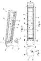
Figure 2 : a perspective view of a filter cleaning device according to an aspect of the present invention; -
Figure 3 : a front view of the filter cleaning device as shown infigure 2 ; -
Figure 4 : a side view of the filter cleaning device as shown infigure 2 ; -
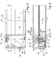
Figure 5 : a partial side view of the filter cleaning device shown infigure 2 with the front plate and other parts being removed and with the brush in a parking position; -
Figure 6 : a cross-section along the line B-B infigure 5 ; -
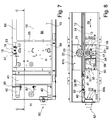
Figure 7 : a partial side view of the filter cleaning device shown infigure 2 with a front plate and other parts being removed and during filter cleaning operation; -
Figure 8 : a cross-section along the line C-C infigure 7 ; -
Figure 9 : the detail D offigure 8 ; -
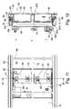
Figure 10 : a partial isometric front view of the filter cleaning device shown infigure 2 with the front plate being removed; -
Figure 11 : a partial front view of the filter cleaning device shown infigure 2 with the brush and its supports as well as the casing being removed; -
Figure 12 : a cross-section along the line D-D infigure 11 -
Figure 13 : a partial isometric top view of the filter cleaning device shown infigure 2 with some parts removed; -
Figure 14 : a partial isometric view of the filter cleaning device shown infigure 2 with some parts removed; -
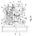
Figure 15 : a partial isometric top view of the filter cleaning device shown infigure 2 with some parts removed; -
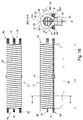
Figure 16 : a) a side view of the brush, b) a front view of the brush to be engaged with the filter surface and c) a cross-section along the line A-A infigure 16a ). -
Figures 2 to 4 generally show afilter cleaning device 10 according to one example. The filter cleaning device comprises acasing 11. Thecasing 11 has acasing inlet 60 and acasing outlet 61. In operation of the air conditioner, air flows through thecasing 11 from thecasing inlet 60 to thecasing outlet 61 passing thefilter 12. - The
filter cleaning device 10 may be mounted to existing air-conditioners such as the one depicted infigure 1 , wherein the existingfilter 12 is first removed from the existing indoor unit and afilter cleaning device 10 is attached to theinlet 2 of the existing casing at aflange 62. Alternatively, thefilter cleaning device 10 as described herein may already be integrated into the casing of an indoor unit of an air conditioner at the time of production of the air conditioner. - A
control box 66 is attached to one side of thecasing 11 and configured to control the cleaning operation of thefilter 12 described later. - The
filter 12 contained in thefilter cleaning device 10 is longitudinal and flat having a length L and a width W. In the example, the length L is larger than the width W, whereby thefilter 12 is longitudinal. Further, the lengths L and the width W are both much larger than the thickness/height, whereby thefilter 12 is flat. - Further, the
filter 12 comprises aframe 63 of plastic material, which is molded about amesh 64 made of plastic material, metal or other suitable material. One longitudinal reinforcingrib 15 and a plurality of transverse reinforcingribs 65 are provided in order to stabilize themesh 64 over the length and widths of thefilter 12. The filter has afirst filter surface 13 facing theinlet 60 and asecond filter surface 14 facing theoutlet 61. The first and second filter surfaces 13, 14 can be best seen infigure 6 . - The
filter cleaning device 10 further comprises a cleaning unit 67 configured to clean thefilter 12 and particularly itsmesh 64. The cleaning unit 67 comprises cleaningmember unit 67a and acounter surface unit 67b. - The cleaning
member unit 67a has amechanical cleaning member 16 in the form of abrush 17. Thebrush 17 consists of abody 20 from which a plurality ofseparate bristles 21 extend in a radial direction. As can be best seen from the cross-sectional view infigure 9 and the perspective infigure 14 , thebrush 17 has a cylindrical shape and is rotatable about an axis ofrotation 19, which corresponds to the center axis of the cylinder. The axis ofrotation 19 is preferably parallel to thefilter surface 13. Furthermore, the axis ofrotation 19 of thebrush 17 is disposed in a distance to thefilter surface 13 which is smaller than the diameter of the brush to ensure contact of thebrush 17 with thefilter surface 13. Yet, the distance is according to the example larger than the diameter of thebody 20 to prevent any damaging of the filter by thebrush 17. - Considering
figure 14 , thebrush 17 is basically supported at both its axial ends 18 bysupports brush 17. - The
lower support 43b is embodied as adust box 28. In particular, thelower support 43b has a bottom 100 andsidewalls 101 surrounding the bottom, whereby thedust box 28 is formed (seefigure 14 ). - The
upper support 43a and thelower support 43b of the support unit are respectively provided with twowheels 45a, b. Thewheels 45a of theupper support 43a are rotatably fixed to theupper support 43a or an upper portion of awall 88 of ahousing 30 connecting thesupports housing 30 connects to theside walls 100 of thedust box 28 and provides for a shielding effect as described in more detail below. Thewheels 45a are rotatable about an axis ofrotation 69. - The
wheels 45b of thelower support 43b are rotatably and pivotably fixed to thelower support 43b or a lower portion of thewall 88 of thehousing 30. In particular, thewheels 45b are rotatably fixed to apivot arm 71 about an axis ofrotation 69 and thepivot arm 71 is pivotably fixed to thelower support 43b or a lower portion of thewall 88 of thehousing 30 about apivot 70. Furthermore, a spring (as an example of the second elastic member) 47 is fixed at one of its opposite ends to thepivot arm 41 of onewheel 45b and the other one of its opposite ends to the pivot arm of theother wheel 45b. Accordingly, thewheels 45b are urged towards each other about thepivots 70. - The
wheels 45a at the top are engaged with a longitudinaltop guide rail 44a (guide) extending in a length direction of thefilter 12 along thefilter cleaning device 10. The same applies for thewheels 45b at the bottom, which are engaged with a longitudinalbottom guide rail 44b (guide) extending substantially in parallel to thetop guide rail 44a. - Accordingly, the support unit is movably guided between the
guide rails filter 12 or itsfilter surface 13, respectively. - The
filter 12 and consequently also theguide rails guide rails figure 12 with respect to thecounter surface unit 67b) parallel to thefilter surface 13 and betweenopposite guide rails guide rails wheels 45b of thelower support 43b are urged towards each other by thespring 47 about thepivots 70. Accordingly, thewheels 45b are urged towards a position in which their distance D to thewheels 45a at theupper support 43a is the largest. Thus, if the distance D between theopposite guide rails wheels 45b pivot counterclockwise (leftwheel 45b infigure 10 ) and clockwise (right wheel 45b infigure 10 ) about thepivot 70 by the force of thespring 47. Thereby, thewheels 45b at thelower support 43b remain securely engaged with thelower guide rail 44b as do thewheels 45a at theupper support 43a. Similar, if the distance D betweenopposite guide rails wheels 45b pivot in the opposite direction, thereby automatically compensating for the change in distance D. Accordingly, support unit may reliably be moved along theguide rails - As previously mentioned, the
brush 17 is rotatably supported in the support unit. As a result, the support unit serves to move thebrush 17 along thefilter surface 13. For movement of the support unit along thefilter 12, the support unit is driven. - According to one example a rack 72 (see
figure 13 ) is provided extending along thefilter 12 in parallel to theguide rails figure 14 ) which may be a stepping motor. Themotor 46 is attached to theupper support 43a, thus avoiding any possible contact with condensate accumulating at the bottom of the filter cleaning device. Further, themotor 46 is with its axis connected to afirst gear 73 rotatably attached to theupper support 43a. Thefirst gear 73 meshes with asecond gear 74 again meshing with athird gear 75. Also the second andthird gear upper support 43a. Thethird gear 75 meshes with therack 72. - Accordingly, the
motor 46 rotates thefirst gear 73, whereby thesecond gear 74 and thethird gear 75 are rotated. Thus, the rotational force is transmitted via thegears 73 to 75 to therack 72. Therack 72 converts the rotational force into a translational force, whereby the support unit and, hence, thebrush 17 rotatably supported therein, are moved along therack 72 and thereby along thefilter 12. -
Figure 13 additionally shows afourth gear 76 again meshing with therack 72. A centrally arrangedfifth gear 77 meshes with thefourth gear 76 to transfer the rotation to asixth gear 78. The axis ofrotation 19 of thebrush 17 is fixed to the axis of rotation of thesixth gear 78. Accordingly, upon operation of themotor 46 and movement of the support unit along therack 72, the movement of the support unit along therack 72 results in rotation of thefourth gear 76 meshing with therack 72. As a consequence, the translational movement of the support unit along therack 72 is converted into a rotational movement. This rotation is transferred via the centrally arrangedfifth gear 77 to thesixth gear 78 thereby rotating thebrush 17. In this context, if the support unit moves infigure 13 to the right, thefourth gear 76 is rotated clockwise whereby the centrally arrangedfifth gear 77 is rotated counterclockwise and thesixth gear 78 again rotates clockwise. If the support unit moves infigure 13 to the left, thefourth gear 76 is rotated counterclockwise whereby the centrally arrangedfifth gear 77 is rotated clockwise and thesixth gear 78 again rotates counterclockwise. Thus, thebrush 17 is rotated in opposite directions and depending on the direction of movement of the support unit. In particular, thebrush 17 is always rotated in the direction of movement. In other words, the upstream side of thebrush 17 is always rotated against thefilter surface 13 whereas the downstream side of thebrush 17 is always rotated away from thefilter surface 13. - As will be apparent from the above description, only one
motor 46 is used to move the support unit and hence thebrush 17 along thefilter 12 and hence itsfilter surface 13, and to rotate thebrush 17. - Due to the movability of the cleaning
member unit 67a and hence thebrush 17 in a longitudinal direction of thefilter 12 as explained above, the cleaningmember unit 67a may be moved to a parking position shown infigures 5 and 6 during non-cleaning operation of the cleaning unit. It is preferred that the cleaning unit does not overlap with the filter surfaces 13, 14 of thefilter 12 in this parking position as seen in a plan view such as in the cross section offigure 6 or in a front view as shown infigure 5 . Thus it can be prevented that any portion of thefilter 12 is blocked by the cleaning unit during non-cleaning operation, that is during air-conditioning operation. Thus, the cleaning unit does not represent any obstruction to the air flow flowing through thefilter 12 and thewhole filter surface - When the
brush 17 and particularly itsbristles 21 brush along thefilter surface 13 and remove the particulate matter therefrom, particulate matter may adhere to thebristles 21. In order to remove the particulate matter from thebristles 21 and, hence, thebrush 17, the cleaning unit further comprises a first comb shapedmember 48 and a second comb shapedmember 49 which are respectively engaged with thebrush 17 and particularly the bristles 21 (seefigure 16 ). The comb shapedmembers rotation 19 of thebrush 17 along the whole axial lengths of thebrush 17. Thus, the comb shapedmembers figure 16c ). The comb shapedmembers free edge 99 respectively engaged with thebristles 21 of thebrush 17. The opposite edge of the comb shapedmembers comb body 97. As shown infigure 15 , thecomb body 97 is fixed to thehousing 30 or more particularly theback wall 88 of thereof. - The comb shaped
members teeth 102 separated by recesses. In other words, the comb shaped members are configured of a plurality of merlons and crenels. Theteeth 102 extend in the width direction from thecomb body 97. The cross-sectional line A-A extends through one of theteeth 102. The two comb shapedmembers members symmetry 103. In particular, theteeth 102 are angled or inclined as described above. As may be best seen from the cross-section infigure 16c ), the comb shapedmembers symmetry 103. As shown, the comb shapedmembers circle 52 being the outer diameter of thebristles 21 or at least co-axial with the outer diameter of thebristles 21 and drawing a first andsecond tangent member 48 is angled clockwise at a negative angle α- and the second comb shapedmember 48 is angled counterclockwise at a positive angle α+ with their width direction. The absolute value of the angles α is however the same to provide for a symmetric arrangement. In this context, the width direction is preferably drawn as a centerline in the cross-section infigure 16c ) at that position of the comb shaped members having the largest thickness perpendicular to the width direction WD and the length direction LD. Accordingly, if thebrush 17 is rotated clockwise infigure 16c ), the comb shapedmember 48 is inclined towards the direction of rotation of thebrush 17. If thebrush 17 is rotated counterclockwise, the comb shapedmember 49 is inclined towards the direction of rotation of thebrush 17. Accordingly, it can be effectively achieved that thebristles 21 of thebrush 17 and to the recesses between theteeth 102 so that any particulate matter can be scrapped of thebristles 21. - As described above, the
brush 17 may rotate in opposite directions and depending on the movement of the support unit. Thus, if the brush rotates clockwise, the first comb shapedmember 48 serves for removing or loosening the particulate matter from thebristles 21, whereas if the brush rotates counterclockwise, the second comb shapedmember 49 provides for this effect. Thus, a very effective cleaning of thebristles 21 may be affected no matter in which direction thebrush 17 rotates. - Furthermore, a first and
second separation roller first separation 53 is associated to the first comb shapedmember 48 and thesecond separation roller 54 is associated to the second comb shapedmember 49. Bothseparation rollers rotation 19 of thebrush 17. Theseparation rollers members bristles 21 away from thebrush 17 so that the particulate matter falls into or towards thebottom 100 of thedust box 28 by gravity. For this purpose, theseparation rollers 53, 55 are rotated in the same direction as thebrush 17. In particular, theseparation rollers 53, 55 is there a centrifuge particulate matter coming into contact with the separation rollers away from thebrush 17 and the comb shapedmembers separation rollers members rotation 19 of thebrush 17, respectively. - According to one example, two seventh gears 79 (see
figure 13 ) are provided meshing with the centrally arrangedfifth gear 77. These seventh gears 79 are respectively attached to the axes of rotation of the first andsecond separation rollers sixth gear 78 also theseventh gears 79 will be rotated automatically by movement of the support unit along therack 72 and rotation of thefourth gear 76. The axial ends of theseparation rollers seventh gears 79 are rotatably accommodated in thecollars 98 at the bottom of the support unit (lower support 43b) as shown infigure 14 . In the above example, when the support unit moves to the right, bothseventh gears 79 are rotated counterclockwise, whereas bothseventh gears 79 are rotated clockwise when the support unit moves to the left. Accordingly also in this case, themotor 46 is used to rotate the first andsecond separation rollers brush 17. - The support unit further comprises the
housing 30 and apartition 68. Thehousing 30 together with thepartition 68 forms a chamber accommodating thebrush 17. That chamber is communicated with thedust box 28 in which particulate matter brushed off thefilter 12 or its filter surface is retained before being removed by a vacuum source as explained later. Thehousing 30 together with thepartition 68 further defines anopening 31 through which a portion of thebrush 17 extends (seefigure 9 ). Thereby it is ensured that the brush protrudes from thehousing 30 and is capable of contacting and brushing thefilter surface 13. Further, thehousing 30 prevents particulate matter removed from the filter by the brush from being distributed throughout the filter cleaning device. Moreover, thehousing 30 shields thedust box 28 and prevents particulate matter already collected in the dust box from being sucked from the dust box during the air conditioning operation. In addition, the relativelysmall opening 31 enables to reduce exchange of air at thedust box 28, when removing the particulate matter from the dust box using a vacuum source. Thus, building up a relatively high under pressure is simplified. - Moreover, a
suction section 32 as shown infigures 6 ,8 and9 is provided for removing the dust accumulated in thedust box 28 from the dust box. Thesuction section 32 comprises anoutlet 37. Theoutlet 37, which may be a circular opening, has acenter axis 38. Theoutlet 37 is communicated with thedust box 28 via acleaning path 80 having a cleaning opening 81 (seefigure 14 ) opening into thedust box 28. - The
suction section 32 further comprises asuction opening 33 fixed to thecasing 11 of the filter cleaning device. In this example, a fitting extends from thecasing 11 and forms thesuction opening 33 at the inside of thecasing 11, The fitting further has anexhaust opening 82 at the outside of thecasing 11. Thesuction opening 33 and theexhaust opening 82 may be both circular. The center axis of at least thesuction opening 33 is congruent with thecenter axis 38 of theoutlet 37. - In one example, a suction socket 42 (see
figure 2 ) may be communicated to thesuction opening 33 via ahose 83 connected to theexhaust opening 82 at one end and to thesuction socket 42 at the other end. Thesuction socket 42 may be configured to receive a fitting and/or a hose of a common vacuum cleaner and may be accessible in the false ceiling U or a false wall without the necessity to remove a part of the ceiling or a wall. Further, it may as well be conceivable to dispose thesuction socket 42 outside the room to be conditioned via the air conditioner. Thus, cleaning personal is enabled to remove dust from thedust box 28 without having to enter the room to be conditioned such as the hotel room or a meeting room. - Once the cleaning operation is finished, the cleaning unit moves towards the left in
figure 8 until it reaches the parking position mentioned above. In this parking position theoutlet 37 is communicated with thesuction opening 33, whereby thedust box 28 is communicated via thecleaning opening 81, the cleaningpath 80, theoutlet 37 to thesuction opening 33 and, hence, to theexhaust opening 82. - A sealing
member 34 is provided at anarea 35 surrounding theoutlet 37 and/or anarea 36 surrounding thesuction opening 33. Upon movement of the cleaning unit to the parking position, the sealing 34 is sandwiched and pressed between thearea 35 and thearea 36 and theoutlet 37 is communicated with thesuction opening 33. In order to be sufficiently pressed, the steppingmotor 46 is controlled by thecontrol box 66. Upon a feedback of a positioning sensor (such as a limit switch) that the cleaning unit has reached the parking position the control is configured to move the cleaning unit towards the left (in the direction of the parking position) at least one additional distance (one or more steps of the stepping motor). Accordingly a relatively tight and reliable seal can be achieved. - Additionally or alternatively to the sealing 34, a
shroud 84 may be provided surrounding theoutlet 37 or thesuction opening 33. Upon reaching the parking position, theshroud 84 enters into thesuction opening 33 and engages with an inner circumferential surface of thesuction opening 33, thereby achieving a sealing effect. However, to achieve a reliable and sufficient sealing, relatively small tolerances regarding the inner diameter of thesuction opening 33 and the outer diameter of theshroud 84 are required. For this reason, the above-described sealing 34 is preferred. In one embodiment, theshroud 84 may, hence, dispense the sealing function and merely provide for centering theoutlet 37 relative to thesuction opening 33. For this purpose, theshroud 84 may have a tapering 85 towards thesuction opening 33, whereby upon engagement of theshroud 84 in the suction opening 33 a self-centering effect is obtained. - Moreover, a
lid 39 is fixed to thecasing 11 as best shown infigures 7 and 8 . More particular, thelid 39 in this example is rotatably fixed to thecasing 11 about therotation axis 85. In this example thelid 39 is comprised of a covering 86 forming acavity 41 and anactuating arm 40. The covering 86 and thecavity 41 are located on one side relative to theaxis 85 and theactuating arm 40 is located on the other side relative to theaxis 85. Thelid 39 is urged about theaxis 85 counterclockwise by a leg spring 87 (third elastic member). In particular and with reference to the following description of its function, thelid 39 is urged towards an opening position. - When the cleaning unit is moved towards the parking position (e.g. from the position in
figure 8 towards the left), the left end of thehousing 30 or any other part of the cleaning unit comes in contact (engages) with theactuating arm 40. Accordingly, the cleaning unit pushes theactuating arm 40 in a clockwise direction about theaxis 85. Thereby the covering 86 is rotated toward thehousing 30 against the force of theleg spring 87. In the parking position, shown infigures 5 and 6 , the covering 86 closes theopening 31 of thehousing 30 and thecavity 41 accommodates that portion of thebrush 17 protruding from theopening 31.Lid 39 is, thus, capable of preventing any particulate matter accumulated in thedust box 28 from leaving thedust box 28 and thehousing 30 during air-conditioning operation. - In this parking position also the
outlet 37 and thesuction opening 33 are communicated. Thus, upon plugging a fitting of a vacuum cleaner into thesuction socket 42 and applying a suction force, particulate matter accommodated in thedust box 28 is sucked from thedust box 28. Further and due to the pressure reduction within thedust box 28, the covering 86 is sucked against the edge of theopening 31 of the housing. In another example, it may, hence, well be to dispense theactuating arm 40 and to merely close thelid 39 by the suction force applied by the vacuum cleaner in the parking position. In this example, however theopening 31 will only be closed during cleaning of thedust box 28 and the effect of preventing particulate matter from being drawn from thedust box 28 during the air conditioning operation is dispensed. Yet, closing of theopening 31 by thelid 39 also provides for a more effective cleaning of thedust box 28 as compared to a non-sealed opening. In particular, a higher under pressure may be built up within thedust box 28 leading to a more effective or more complete cleaning of thedust box 28 by the vacuum cleaner. - The cleaning unit further comprises the
counter surface unit 67b. Thecounter surface unit 67b comprises a counter surface 22 (seefigures 11 and 12 ). In this example, thecounter surface 22 is formed by theouter surface 25 of acylinder 26. Thecylinder 26 is rotatably supported in a supporting unit formed by anupper support 43c and alower support 43d connected by aback wall 88. The support unit is configured very similar to that of the cleaningmember unit 67a and comprises twoupper wheels 45c and tolower wheels 45d wherein thewheels member unit 67a and as shown infigure 10 . Accordingly and in order to avoid repetition these elements are not described in more detail at this stage. Similar,motor 46 is also provided in the support unit (figure 11 ). Themotor 46 is with its axis connected toeighth gear 94 meshing with aninth gear 95 again meshing with atenth gear 96 meshing with therack 72. Thus, the support unit of thecounter surface unit 67b is moved along therack 72 upon operation of themotor 46 in the same manner as the support unit of the cleaningmember unit 67a and further description is omitted. - The
cylinder 26 comprises acylinder axis 27 which is at the same time the axis of rotation of thecylinder 26. Thecylinder 26 has at its center in the axial direction anannular groove 24. As can be best seen fromfigures 11 and 12 theannular groove 24 accommodates the longitudinal reinforcingrib 15 of thefilter 12. Thereby it can be ensured that theouter surface 25 of the cylinder reliably pushes themesh 64 of thefilter 12 against thebristles 21 of thebrush 17 and closes themesh 64 at thefilter surface 14 in order to prevent particulate matter from being pressed through themesh 64. Certainly, a plurality of suchannular grooves 24 can be provided if a plurality of longitudinal reinforcingribs 15 is provided. - In the shown example, the
cylinder 26 is hollow. For ease of production, thecylinder 26 can be produced fromhalf shells 89. Thehalf shells 89 are each half circular in cross section and, thus, a half cylindrical. The half shells may be at one end be connected by a living or integral hinge. In addition, the axis ofrotation 27 may be integrally formed with one of thehalf shells 89. For this purpose, two coaxial protrusions may extend from the axial end of the half shells in an axial direction. Thus, thecylinder 26 may be injection molded from plastic material. To form thecylinder 26, thehalf shells 89 are rotated about the living hinge and fixed together bylatches 90 at one of thehalf shells 89 andcorresponding hooks 91 at the other one of thehalf shells 89. Certainly also other methods for fixing the half shells may be used. Also the half shells may be formed separately and then be fixed together without the use of a living hinge. - Furthermore, the
filter 12 may along its length not to be completely flat but bend in a direction towards thecounter surface unit 67b and/or the cleaningmember unit 67a or even wavy. Accordingly, it could happen that either thebrush 17 comes out of contact with thefilter surface 13 reducing cleaning efficiency or that thebrush 17 is pushed into thefilter surface 13 to heavily with the risk of damaging the filter. To cope with this problem, thecylinder 26 and hence thecounter surface 21, formed by theouter surface 25 of thecylinder 26, is urged towards thefilter surface 14. - As one example, the axis of
rotation 27 of thecylinder 26 is guided in a long hole 92 (also seefigure 15 ). The longitudinal direction of thelong hole 92 extends in a direction perpendicular to thefilter surface 14. Accordingly, thecylinder 26 may move in a direction perpendicular to thefilter surface 14. A leg spring 23 (as an example of a first elastic member) is provided in order to urge thecylinder 26 in a direction towards thefilter surface 14. More particularly, the axis ofrotation 27 of thecylinder 26 is rotatably fixed to acarriage 93. Thecarriage 93 is translationally movable in the long hole. Accordingly and even though thecounter surface 22 formed by theouter surface 25 of thecylinder 26 is rigid in a radial direction, the movability of thecylinder 26 in a direction perpendicular to thefilter surface 14 accommodates changes in the distance of thefilter surface 14 to theouter surface 25 due to unevenness of thefilter 12 along its length. Accordingly the filter is always reliably pressed against the rotatingbrush 17 or more particularly itsbristles 21 at a relatively constant force so that a high cleaning efficiency may be achieved without the risk of damaging the filter. - In the present example, the cleaning
member unit 67a and thesupport surface unit 67b are respectively formed independent and separate from each other. More particularly, the support units are formed separately. Accordingly, thefilter cleaning device 10 may have a relatively low width (or height) being substantially dependent on the width of thefilter 12. However in alternative embodiments, the support units may also be connected above and/or below theframe 63 of thefilter 12. This would provide for the advantage that if and only onemotor 46 would be required for bothunit - In the following, the function of the above-described filter cleaning device will be explained.
- In the non-cleaning operation and during air-conditioning operation, the cleaning unit including the
brush 17 and thecounter surface 22 is positioned in the parking position shown infigures 2 to 6 . - First, the control considers whether cleaning operation is required. In this context, different parameters and can trigger that cleaning operation is required. As one example, the cleaning operation is performed in a predetermined time interval. Alternatively, a sensor may be provided capable of measuring a degree of particulate matter on the filter such as a sensor capable of measuring a flow resistance of air flowing through the filter. The output of this sensor may be used by the control to trigger the cleaning operation. Certainly, also other para meters may be used for this purpose.
- Once cleaning operation is started, the control in the
control box 66 cooperates with the control of the air conditioner to temporarily stop the air conditioning operation. Subsequently, themotors 46 are activated. Accordingly, the cleaningmember unit 67a and the support surface unit are moved from the left to the right along the filter surfaces 13, 14 respectively, wherein the rotational force of themotors 46 is transferred via thegears 73 to 75 to therack 72 and thegears 94 to 96 to therack 72. At the same time thebrush 17 is rotated, wherein the translational movement of the support unit of the cleaningmember unit 67a along therack 72 is converted and transmitted via thegears rotation 19 of thebrush 17, thereby rotating thebrush 17 clockwise. Accordingly thebristles 21 brush particular matter from thefilter surface 14 away from thefilter surface 14 whereby the particulate matter is transferred by thebrush 17 through theopening 31 into thehousing 30 and subsequently falls into thedust box 28 by gravity. - In the
housing 30, the particulate matter is scrapped away from thebristles 21 by the first comb shapedmember 48. Thefirst separation roller 53 being rotated by thegear 79 in a counterclockwise direction ensures that the particulate matter scrapped away from thebristles 21 by the first comb shapedmember 48 is moved away from thebristles 21. The thus separated particulate matter will then fall into thedust box 28 or particularly towards itsbottom 100 by gravity and will be collected at the bottom 100 of the dust box 28 (lower support 43b). - The
counter surface 22 formed by theouter surface 25 of thecylinder 26 is moved together with thebrush 17 along thefilter 12 being in contact with theopposite filter surface 14. In particular, a line connecting the axis ofrotation 27 and the axis ofrotation 19 is perpendicular to the filter surfaces 13, 14. Accordingly, thecounter surface 22 supports thefilter 12 at the side of thefilter surface 14 so as to keep themesh 64 in contact with thebristles 21 of thebrush 17. During the movement of thebrush 17 and thecounter surface 21 along thefilter 12, thecounter surface 22 may compensate for any deviations of thefilter 12 from an evenly flat shape in that it may move perpendicular to the filter surfaces 13, 14 within thelong hole 92. Further, as thecounter surface 22 is urged towards the filter surfaces 13, 14 by theleg spring 23, thebristles 21 are engaged with thefilter surface 13 at a relatively constant pressure/force along the length of the filter. Accordingly, an efficient and reliable cleaning can be performed without the risk of damaging the filter. - Further, it is to mention that the
counter surface 22 particularly thecylinder 26 is not actively driven or rotated, but rotates because of its frictional contact with thefilter surface 14. When the cleaning unit moves to the right, thecylinder 26 hence rotates in the same direction as thebrush 17, that is clockwise. Due to the rotation of the counter surface and its curved shape, the contact area and the friction between the contact area and thefilter surface 14 is relatively low so that any damaging of thefilter 12 by thecounter surface 22 can reliably be prevented. - Once the cleaning unit has reached the end of the
filter 12 opposite to the parking position, the rotation direction of themotors 46 is switched. This can for example be triggered by the cleaning unit moving against a limit switch, thereby switching themotors 46. Yet, also other control mechanisms are conceivable. Switching the rotational direction of themotors 46 changes the rotational direction of allgears 33 to 79 and 94 to 96. Accordingly, thebrush 17 is rotated counterclockwise as are theseparation rollers cylinder 26 is again rotated by frictional engagement with thefilter surface 14, however, now counterclockwise. During movement in this direction, the second comb shapedmember 49 and thesecond separation roller 54 are active for scrapping the particulate matter from thebristles 21 and move the scrapped of particulate matter away from thebristles 21 for being collected in thedust box 28. - The above process may be repeated as required until the cleaning operation is finished. If a command has been provided by the control in the
control box 66 that the cleaning operation can be terminated, the cleaning unit is again moved to the parking position. During this movement and as previously indicated, thehousing 30 of the cleaning unit engages with/comes into contact with theactuating arm 40 thereby pivoting thelid 39 around theaxis 85 in a clockwise direction, whereby the covering 86 closes theopening 31 in thehousing 30. If the cleaning unit has reached the parking position which may be indicated to the control by the use of a sensor or a limit switch, themotors 46 are activated to perform at least one more step towards the parking position in order to press the sealing 34 and securely communicate theoutlet 37 and thesuction opening 33. Subsequently, the cleaning operation is finished. - The cleaning personal in the premises in which the filter cleaning devices are mounted may in a regular interval then plug a fitting of the vacuum cleaner into the
suction socket 42 and thereby apply a sucking force to thesuction opening 33, whereby particulate matter accumulated at the bottom 100 of thedust box 28 is sucked from thedust box 28 via thecleaning opening 81, the cleaningpath 80, theoutlet 37, thesuction opening 33, theexhaust opening 82, thehose 83 and thesuction socket 42 into the vacuum cleaner. According to an alternative example, it may be conceivable to connect the control in thecontrol box 66 to a network within the premises and to output a signal that the cleaning operation has been performed to the network so as to indicate to the cleaning personal that thedust box 28 is to be emptied. It is also possible to provide a visual indicator such as a light at thesuction section 42, which could indicate to the cleaning personal that emptying thedust box 28 is required (for example a red light for cleaning and a green light for non-cleaning requirement). Instead of using a predetermined interval as requirement for removing the particulate matter from thedust box 28 or triggering the necessity to empty thedust box 28 by the termination of the cleaning operation, sensors outputting information on the amount of particulate matter accumulated in thedust box 28 can be used. This information can be outputted to the network or used to control the visual indicator. In a preferred embodiment, thesuction section 42 is disposed outside the space to be conditioned, whereby the cleaning personal does not need to enter this space for emptying thedust box 28. - As will be apparent from the above description, the filter cleaning device described above provides for a very efficient system overcoming the problems adhering to the prior art to at least to some extent.
Reference list Air conditioner 1 Inlet 2 Outlet 3 Heat exchanger 4 Fan 5 Air ducting 6, 7 Exit grating 8 Inlet grating 9 Filter cleaning device 10 Casing 11 Filter 12 Filter surface 13, 14 Width of the filter W Length of the filter L Longitudinal reinforcing rib 15 Cleaning member 16 Brush 17 Axial end of the brush 18 Axis of rotation (cylinder axis) 19 Body 20 Bristles 21 Counter surface 22 First elastic member 23 Annular groove 24 Outer surface 25 Cylinder 26 Axis 27 Dust box 28 Direction of movement 29 Housing 30 Opening 31 Suction section 32 Suction opening 33 Sealing 34 Area surrounding the outlet 35 Area surrounding the suction opening of the casing 36 Outlet 37 Center axis 38 Lid 39 Actuating arm 40 Cavity 41 Suction socket 42 Support 43 a-d Guide 44 a-d Wheel 45 a-d Motor 46 Second elastic member 47 First comb shaped member 48 Second comb shaped member 49 Length direction LD Width direction WD First tangent 50 Second tangent 51 Circle 52 Positive angle α+ Negative angle α- First separation roller 53 Second separation roller 54 Casing inlet 60 Casing outlet 61 Flange 62 Frame 63 Mesh 64 Transverse reinforcing rib 65 Control box 66 Cleaning unit 67a-b Partition 68 Axis of rotation 69 Pivot 70 Pivot arm 71 Rack 72 first gear 73 second gear 74 third gear 75 fourth gear 76 fifth gear 77 sixth gear 78 seventh gear 79 Cleaning path 80 Cleaning opening 81 Exhaust opening 82 Hose 83 Shroud 84 Rotation axis 85 Covering 86 third elastic member 87 Back wall 88 Half shells 89 Latch 90 Hook 91 Long hole 92 Carriage 93 eighth gear 94 ninth gear 95 tenth gear 96 Comb body 97 Collar 98 Free edge 99 Bottom 100 Side walls 101 Teeth 102 Axis of symmetry 103
Claims (13)
- Filter cleaning device for an air conditioner (1), particularly a duct-type air conditioner, the filter cleaning device comprising:- a casing (11);- a filter (12) disposed in the casing and to be passed through by an air flow, the filter having a filter surface (13);- a cleaning member (16) contactable with the filter surface (13) for removing particulate matter from the filter surface; and- a dust box (28) for receiving the particulate matter, the dust box comprising a housing (30) accommodating the cleaning member and having an opening (31) through which the cleaning member protrudes from the housing for contacting the filter surface,- a suction section (32) configured to apply a suction force to the dust box for removing received particulate matter from the dust box, wherein the suction section comprises an outlet (37) in the housing to be communicated with the suction force; and- a lid (39) movable between a first position and a second position, the lid closing the opening (31) of the housing in the second position, wherein the lid is in the second position when the suction force is applied.
- Filter cleaning device according to claim 1, wherein the dust box (28) is translationally moveable along the filter surface (13) and the lid (39) is movable into the second position when the dust box is in a parking position.
- Filter cleaning device according to claim 2, wherein the suction section (32) further comprises a suction opening (33) in the casing (11), wherein the outlet (37) of the dust box is connectable to the suction opening upon the movement of the dust box (28) into the parking position.
- Filter cleaning device according to claim 3, wherein the outlet (37) has a center axis (38) substantially parallel to the direction of said movement of the dust box (28).
- Filter cleaning device according to claim 3 or 4, further comprising a sealing (34), wherein the sealing is sandwiched between an area (35) surrounding the outlet (37) and an area (36) surrounding the suction opening (33) of the casing, when the outlet and the suction opening are connected, and is pressed by movement of the dust box (28) in the direction of the suction opening.
- Filter cleaning device according to anyone of claims 2 to 5, wherein the housing (30) is disposed outside the filter surface (13) when the dust box (28) is in the parking position.
- Filter cleaning device according to anyone of claims 2 to 6, wherein the lid (39) is moveably fixed relative to the casing (11) and comprises an actuating arm (40) engageable with the dust box (28) upon movement of the dust box in the direction of the parking position, whereby the lid is moved from the first position into the second position.
- Filter cleaning device according to anyone of claims 1 to 6, wherein the lid (39) is movable into the second position by the suction force.
- Filter cleaning device according to any one of the preceding claims, wherein the lid (59) is rotatably fixed relative to the casing (11) so as to be rotatable between the first and second positions.
- Filter cleaning device according to any one of the preceding claims, wherein the lid (39) is biased in the direction of the first position.
- Filter cleaning device according to any one of the preceding claims, wherein the lid (39) defines a cavity (41) wherein the cavity, in the second position of the lid, accommodates that part of the cleaning member (16) protruding through the opening (31) from the housing (30).
- Air conditioner, particularly a duct-type air conditioner, the air conditioner having a filter cleaning device (10) according to any one of the preceding claims.
- Air conditioner according to claim 12, the air conditioner having a filter cleaning device (10) having the features of any one of claims 3 to 5, further comprising a suction socket (42) fluidly connected to the suction opening (33) of the casing (11) and configured for receiving a hose of a vacuum cleaner providing for the suction force, whereby the particulate matter received in the dust box (28) is removed from the dust box by the vacuum cleaner.
Priority Applications (5)
| Application Number | Priority Date | Filing Date | Title |
|---|---|---|---|
| EP16181791.1A EP3276276B1 (en) | 2016-07-28 | 2016-07-28 | Filter cleaning device for an air conditioner and air conditioner having such filter cleaning device |
| US16/321,084 US11231190B2 (en) | 2016-07-28 | 2017-07-25 | Filter cleaning device for an air conditioner and air conditioner having such filter cleaning device |
| CN201780046111.8A CN109790998B (en) | 2016-07-28 | 2017-07-25 | Filter cleaning equipment and air conditioners |
| PCT/JP2017/026852 WO2018021304A1 (en) | 2016-07-28 | 2017-07-25 | Filter cleaning device for an air conditioner and air conditioner having such filter cleaning device |
| AU2017303170A AU2017303170B2 (en) | 2016-07-28 | 2017-07-25 | Filter cleaning device for an air conditioner and air conditioner having such filter cleaning device |
Applications Claiming Priority (1)
| Application Number | Priority Date | Filing Date | Title |
|---|---|---|---|
| EP16181791.1A EP3276276B1 (en) | 2016-07-28 | 2016-07-28 | Filter cleaning device for an air conditioner and air conditioner having such filter cleaning device |
Publications (2)
| Publication Number | Publication Date |
|---|---|
| EP3276276A1 true EP3276276A1 (en) | 2018-01-31 |
| EP3276276B1 EP3276276B1 (en) | 2021-11-03 |
Family
ID=56551349
Family Applications (1)
| Application Number | Title | Priority Date | Filing Date |
|---|---|---|---|
| EP16181791.1A Active EP3276276B1 (en) | 2016-07-28 | 2016-07-28 | Filter cleaning device for an air conditioner and air conditioner having such filter cleaning device |
Country Status (5)
| Country | Link |
|---|---|
| US (1) | US11231190B2 (en) |
| EP (1) | EP3276276B1 (en) |
| CN (1) | CN109790998B (en) |
| AU (1) | AU2017303170B2 (en) |
| WO (1) | WO2018021304A1 (en) |
Cited By (4)
| Publication number | Priority date | Publication date | Assignee | Title |
|---|---|---|---|---|
| CN111602982A (en) * | 2020-06-11 | 2020-09-01 | 北京中航科电测控技术股份有限公司 | Automatically controlled cabinet of keeping secret with internal environment monitor function |
| CN112902352A (en) * | 2021-01-19 | 2021-06-04 | 苏州新进元网络科技有限公司 | Air odor removing filter with self-sealing device |
| CN113834158A (en) * | 2021-09-28 | 2021-12-24 | 西安市建筑设计研究院有限公司 | Heating ventilation air conditioner device in closed environment |
| CN115288283A (en) * | 2022-01-24 | 2022-11-04 | 衢州学院 | Assembled building structure for villa with heat preservation effect |
Families Citing this family (9)
| Publication number | Priority date | Publication date | Assignee | Title |
|---|---|---|---|---|
| US12134058B2 (en) | 2021-05-24 | 2024-11-05 | Lg Electronics Inc. | Filter cleaner and air-processing apparatus including filter cleaner |
| US12480667B2 (en) | 2021-05-24 | 2025-11-25 | Lg Electronics Inc. | Air-conditioning system |
| US12385666B2 (en) | 2021-05-24 | 2025-08-12 | Lg Electronics Inc. | Air-processing apparatus |
| US12326277B2 (en) | 2021-05-24 | 2025-06-10 | Lg Electronics Inc. | Air-conditioning system |
| US12474068B2 (en) | 2021-05-24 | 2025-11-18 | Lg Electronics Inc. | Air-conditioning system |
| CN113566357A (en) * | 2021-07-21 | 2021-10-29 | 威尔登环保设备(长沙)有限公司 | air filter |
| US12209771B1 (en) * | 2021-11-29 | 2025-01-28 | Amazon Technologies, Inc. | Air filtration system for datacenter or other building |
| CN114251762B (en) * | 2021-12-16 | 2023-05-05 | 江苏凯联建筑设计有限公司 | Fresh air device for air conditioning room |
| WO2026108954A1 (en) * | 2024-11-21 | 2026-05-28 | 深圳市晨北科技有限公司 | Filtering apparatus and cleaning method therefor |
Citations (8)
| Publication number | Priority date | Publication date | Assignee | Title |
|---|---|---|---|---|
| JPH0632926U (en) | 1992-09-18 | 1994-04-28 | 株式会社富士通ゼネラル | Air conditioner |
| KR20030083185A (en) | 2002-04-19 | 2003-10-30 | 엘지전자 주식회사 | A duct type air conditioner |
| KR20040080810A (en) | 2003-03-13 | 2004-09-20 | 엘지전자 주식회사 | A duct type air-conditioner |
| WO2007040276A1 (en) | 2005-10-06 | 2007-04-12 | Matsushita Electric Industrial Co., Ltd. | Air conditioner |
| EP1927813A1 (en) * | 2005-08-30 | 2008-06-04 | Toshiba Carrier Corporation | Indoor machine of air conditioner |
| WO2010143230A1 (en) * | 2009-06-11 | 2010-12-16 | 日立アプライアンス株式会社 | Air conditioner |
| JP2014020658A (en) * | 2012-07-18 | 2014-02-03 | Hitachi Appliances Inc | Ceiling-embedded air conditioner |
| WO2016009351A1 (en) | 2014-07-14 | 2016-01-21 | Airvac Limited | An air conditioning filter cleaner and filter cleaning system |
Family Cites Families (11)
| Publication number | Priority date | Publication date | Assignee | Title |
|---|---|---|---|---|
| EP1762790B1 (en) * | 2005-09-13 | 2010-12-15 | Fujitsu General Limited | Air conditioner with a filter cleaning arrangement |
| KR100867956B1 (en) | 2006-12-08 | 2008-11-11 | 엘지전자 주식회사 | Air conditioner |
| US8343244B2 (en) * | 2007-07-31 | 2013-01-01 | Daikin Industries, Ltd. | Air conditioner and extension nozzle of cleaner used for the same |
| JP5294440B2 (en) | 2007-09-28 | 2013-09-18 | 株式会社コーワ | Air conditioner |
| KR101329755B1 (en) * | 2008-01-28 | 2013-11-14 | 엘지전자 주식회사 | Ceiling type air conditioner |
| JP5387855B2 (en) * | 2010-02-15 | 2014-01-15 | 株式会社富士通ゼネラル | Air conditioner |
| JP5423995B2 (en) * | 2011-01-19 | 2014-02-19 | 株式会社富士通ゼネラル | Air conditioner |
| KR102199380B1 (en) * | 2014-01-17 | 2021-01-06 | 엘지전자 주식회사 | Air conditioner |
| CN105588319B (en) * | 2015-07-29 | 2019-03-19 | 海信(山东)空调有限公司 | A kind of cleaning structure of air-conditioning filter net |
| CN205425160U (en) * | 2015-11-30 | 2016-08-03 | 美的集团武汉制冷设备有限公司 | Wall -mounting type air conditioner |
| CN105352043B (en) * | 2015-11-30 | 2018-03-27 | 美的集团武汉制冷设备有限公司 | Hanging air conditioner |
-
2016
- 2016-07-28 EP EP16181791.1A patent/EP3276276B1/en active Active
-
2017
- 2017-07-25 AU AU2017303170A patent/AU2017303170B2/en not_active Ceased
- 2017-07-25 CN CN201780046111.8A patent/CN109790998B/en not_active Expired - Fee Related
- 2017-07-25 US US16/321,084 patent/US11231190B2/en not_active Expired - Fee Related
- 2017-07-25 WO PCT/JP2017/026852 patent/WO2018021304A1/en not_active Ceased
Patent Citations (8)
| Publication number | Priority date | Publication date | Assignee | Title |
|---|---|---|---|---|
| JPH0632926U (en) | 1992-09-18 | 1994-04-28 | 株式会社富士通ゼネラル | Air conditioner |
| KR20030083185A (en) | 2002-04-19 | 2003-10-30 | 엘지전자 주식회사 | A duct type air conditioner |
| KR20040080810A (en) | 2003-03-13 | 2004-09-20 | 엘지전자 주식회사 | A duct type air-conditioner |
| EP1927813A1 (en) * | 2005-08-30 | 2008-06-04 | Toshiba Carrier Corporation | Indoor machine of air conditioner |
| WO2007040276A1 (en) | 2005-10-06 | 2007-04-12 | Matsushita Electric Industrial Co., Ltd. | Air conditioner |
| WO2010143230A1 (en) * | 2009-06-11 | 2010-12-16 | 日立アプライアンス株式会社 | Air conditioner |
| JP2014020658A (en) * | 2012-07-18 | 2014-02-03 | Hitachi Appliances Inc | Ceiling-embedded air conditioner |
| WO2016009351A1 (en) | 2014-07-14 | 2016-01-21 | Airvac Limited | An air conditioning filter cleaner and filter cleaning system |
Cited By (7)
| Publication number | Priority date | Publication date | Assignee | Title |
|---|---|---|---|---|
| CN111602982A (en) * | 2020-06-11 | 2020-09-01 | 北京中航科电测控技术股份有限公司 | Automatically controlled cabinet of keeping secret with internal environment monitor function |
| CN111602982B (en) * | 2020-06-11 | 2021-06-01 | 北京中航科电测控技术股份有限公司 | Automatically controlled cabinet of keeping secret with internal environment monitor function |
| CN112902352A (en) * | 2021-01-19 | 2021-06-04 | 苏州新进元网络科技有限公司 | Air odor removing filter with self-sealing device |
| CN113834158A (en) * | 2021-09-28 | 2021-12-24 | 西安市建筑设计研究院有限公司 | Heating ventilation air conditioner device in closed environment |
| CN113834158B (en) * | 2021-09-28 | 2022-12-09 | 西安市建筑设计研究院有限公司 | HVAC unit in a closed environment |
| CN115288283A (en) * | 2022-01-24 | 2022-11-04 | 衢州学院 | Assembled building structure for villa with heat preservation effect |
| CN115288283B (en) * | 2022-01-24 | 2023-08-22 | 衢州学院 | Building structure with heat preservation effect for assembled villa |
Also Published As
| Publication number | Publication date |
|---|---|
| US20190170377A1 (en) | 2019-06-06 |
| US11231190B2 (en) | 2022-01-25 |
| WO2018021304A1 (en) | 2018-02-01 |
| EP3276276B1 (en) | 2021-11-03 |
| CN109790998A (en) | 2019-05-21 |
| AU2017303170B2 (en) | 2019-10-17 |
| CN109790998B (en) | 2021-06-25 |
| AU2017303170A1 (en) | 2019-01-24 |
Similar Documents
| Publication | Publication Date | Title |
|---|---|---|
| EP3276276B1 (en) | Filter cleaning device for an air conditioner and air conditioner having such filter cleaning device | |
| EP3276275B1 (en) | Filter cleaning device for an air conditioner and air conditioner having such filter cleaning device | |
| EP3276278B1 (en) | Filter cleaning device for an air conditioner and air conditioner having such filter cleaning device | |
| EP3276277B1 (en) | Filter cleaning device for an air conditioner and air conditioner having such filter cleaning device | |
| KR101146438B1 (en) | Air conditioner and cleaner extension nozzle | |
| JP4206797B2 (en) | Air conditioner | |
| CN111570404B (en) | Automatic cleaning device and air conditioner | |
| CN111043656B (en) | Air conditioning indoor unit and air conditioning system having the same | |
| KR20090022093A (en) | Air conditioner | |
| JP4269141B2 (en) | Air conditioner | |
| CN214804491U (en) | Cleaning base station, cleaning robot and cleaning system | |
| JP2013142521A (en) | Filter cleaning device of air conditioner, and air conditioner | |
| CN214841146U (en) | Warmer capable of automatically cleaning dust filter screen | |
| CN205425160U (en) | Wall -mounting type air conditioner | |
| WO2024114697A1 (en) | Filter screen mechanism and air conditioner indoor unit | |
| CN112539551B (en) | Cleaning device, panel structure and air conditioner | |
| CN223063994U (en) | A combined air-conditioning box fresh air outlet filtering device | |
| CN220083270U (en) | Gas filtering device | |
| CN121184860A (en) | A self-cleaning device for air conditioning filters and a household air conditioner | |
| JP2025064461A (en) | Air conditioners | |
| WO2025252158A1 (en) | Cleaning device and laundry treatment apparatus | |
| JPH04186032A (en) | Ceiling installation type air conditioner | |
| KR20090022101A (en) | Air conditioner | |
| JP2008286515A (en) | Air conditioner |
Legal Events
| Date | Code | Title | Description |
|---|---|---|---|
| PUAI | Public reference made under article 153(3) epc to a published international application that has entered the european phase |
Free format text: ORIGINAL CODE: 0009012 |
|
| STAA | Information on the status of an ep patent application or granted ep patent |
Free format text: STATUS: THE APPLICATION HAS BEEN PUBLISHED |
|
| AK | Designated contracting states |
Kind code of ref document: A1 Designated state(s): AL AT BE BG CH CY CZ DE DK EE ES FI FR GB GR HR HU IE IS IT LI LT LU LV MC MK MT NL NO PL PT RO RS SE SI SK SM TR |
|
| AX | Request for extension of the european patent |
Extension state: BA ME |
|
| STAA | Information on the status of an ep patent application or granted ep patent |
Free format text: STATUS: REQUEST FOR EXAMINATION WAS MADE |
|
| 17P | Request for examination filed |
Effective date: 20180629 |
|
| RBV | Designated contracting states (corrected) |
Designated state(s): AL AT BE BG CH CY CZ DE DK EE ES FI FR GB GR HR HU IE IS IT LI LT LU LV MC MK MT NL NO PL PT RO RS SE SI SK SM TR |
|
| STAA | Information on the status of an ep patent application or granted ep patent |
Free format text: STATUS: EXAMINATION IS IN PROGRESS |
|
| 17Q | First examination report despatched |
Effective date: 20190718 |
|
| REG | Reference to a national code |
Ref country code: DE Ref legal event code: R079 Ref document number: 602016065656 Country of ref document: DE Free format text: PREVIOUS MAIN CLASS: F24F0013280000 Ipc: F24F0008100000 |
|
| GRAP | Despatch of communication of intention to grant a patent |
Free format text: ORIGINAL CODE: EPIDOSNIGR1 |
|
| RIC1 | Information provided on ipc code assigned before grant |
Ipc: F24F 13/28 20060101ALI20210430BHEP Ipc: B01D 46/00 20060101ALI20210430BHEP Ipc: F24F 8/90 20210101ALI20210430BHEP Ipc: F24F 8/10 20210101AFI20210430BHEP |
|
| STAA | Information on the status of an ep patent application or granted ep patent |
Free format text: STATUS: GRANT OF PATENT IS INTENDED |
|
| INTG | Intention to grant announced |
Effective date: 20210609 |
|
| GRAS | Grant fee paid |
Free format text: ORIGINAL CODE: EPIDOSNIGR3 |
|
| GRAA | (expected) grant |
Free format text: ORIGINAL CODE: 0009210 |
|
| STAA | Information on the status of an ep patent application or granted ep patent |
Free format text: STATUS: THE PATENT HAS BEEN GRANTED |
|
| AK | Designated contracting states |
Kind code of ref document: B1 Designated state(s): AL AT BE BG CH CY CZ DE DK EE ES FI FR GB GR HR HU IE IS IT LI LT LU LV MC MK MT NL NO PL PT RO RS SE SI SK SM TR |
|
| REG | Reference to a national code |
Ref country code: GB Ref legal event code: FG4D |
|
| REG | Reference to a national code |
Ref country code: AT Ref legal event code: REF Ref document number: 1444287 Country of ref document: AT Kind code of ref document: T Effective date: 20211115 Ref country code: CH Ref legal event code: EP |
|
| REG | Reference to a national code |
Ref country code: IE Ref legal event code: FG4D |
|
| REG | Reference to a national code |
Ref country code: DE Ref legal event code: R096 Ref document number: 602016065656 Country of ref document: DE |
|
| REG | Reference to a national code |
Ref country code: LT Ref legal event code: MG9D |
|
| REG | Reference to a national code |
Ref country code: NL Ref legal event code: MP Effective date: 20211103 |
|
| REG | Reference to a national code |
Ref country code: AT Ref legal event code: MK05 Ref document number: 1444287 Country of ref document: AT Kind code of ref document: T Effective date: 20211103 |
|
| PG25 | Lapsed in a contracting state [announced via postgrant information from national office to epo] |
Ref country code: RS Free format text: LAPSE BECAUSE OF FAILURE TO SUBMIT A TRANSLATION OF THE DESCRIPTION OR TO PAY THE FEE WITHIN THE PRESCRIBED TIME-LIMIT Effective date: 20211103 Ref country code: LT Free format text: LAPSE BECAUSE OF FAILURE TO SUBMIT A TRANSLATION OF THE DESCRIPTION OR TO PAY THE FEE WITHIN THE PRESCRIBED TIME-LIMIT Effective date: 20211103 Ref country code: FI Free format text: LAPSE BECAUSE OF FAILURE TO SUBMIT A TRANSLATION OF THE DESCRIPTION OR TO PAY THE FEE WITHIN THE PRESCRIBED TIME-LIMIT Effective date: 20211103 Ref country code: BG Free format text: LAPSE BECAUSE OF FAILURE TO SUBMIT A TRANSLATION OF THE DESCRIPTION OR TO PAY THE FEE WITHIN THE PRESCRIBED TIME-LIMIT Effective date: 20220203 Ref country code: AT Free format text: LAPSE BECAUSE OF FAILURE TO SUBMIT A TRANSLATION OF THE DESCRIPTION OR TO PAY THE FEE WITHIN THE PRESCRIBED TIME-LIMIT Effective date: 20211103 |
|
| PG25 | Lapsed in a contracting state [announced via postgrant information from national office to epo] |
Ref country code: IS Free format text: LAPSE BECAUSE OF FAILURE TO SUBMIT A TRANSLATION OF THE DESCRIPTION OR TO PAY THE FEE WITHIN THE PRESCRIBED TIME-LIMIT Effective date: 20220303 Ref country code: SE Free format text: LAPSE BECAUSE OF FAILURE TO SUBMIT A TRANSLATION OF THE DESCRIPTION OR TO PAY THE FEE WITHIN THE PRESCRIBED TIME-LIMIT Effective date: 20211103 Ref country code: PT Free format text: LAPSE BECAUSE OF FAILURE TO SUBMIT A TRANSLATION OF THE DESCRIPTION OR TO PAY THE FEE WITHIN THE PRESCRIBED TIME-LIMIT Effective date: 20220303 Ref country code: PL Free format text: LAPSE BECAUSE OF FAILURE TO SUBMIT A TRANSLATION OF THE DESCRIPTION OR TO PAY THE FEE WITHIN THE PRESCRIBED TIME-LIMIT Effective date: 20211103 Ref country code: NO Free format text: LAPSE BECAUSE OF FAILURE TO SUBMIT A TRANSLATION OF THE DESCRIPTION OR TO PAY THE FEE WITHIN THE PRESCRIBED TIME-LIMIT Effective date: 20220203 Ref country code: NL Free format text: LAPSE BECAUSE OF FAILURE TO SUBMIT A TRANSLATION OF THE DESCRIPTION OR TO PAY THE FEE WITHIN THE PRESCRIBED TIME-LIMIT Effective date: 20211103 Ref country code: LV Free format text: LAPSE BECAUSE OF FAILURE TO SUBMIT A TRANSLATION OF THE DESCRIPTION OR TO PAY THE FEE WITHIN THE PRESCRIBED TIME-LIMIT Effective date: 20211103 Ref country code: HR Free format text: LAPSE BECAUSE OF FAILURE TO SUBMIT A TRANSLATION OF THE DESCRIPTION OR TO PAY THE FEE WITHIN THE PRESCRIBED TIME-LIMIT Effective date: 20211103 Ref country code: GR Free format text: LAPSE BECAUSE OF FAILURE TO SUBMIT A TRANSLATION OF THE DESCRIPTION OR TO PAY THE FEE WITHIN THE PRESCRIBED TIME-LIMIT Effective date: 20220204 Ref country code: ES Free format text: LAPSE BECAUSE OF FAILURE TO SUBMIT A TRANSLATION OF THE DESCRIPTION OR TO PAY THE FEE WITHIN THE PRESCRIBED TIME-LIMIT Effective date: 20211103 |
|
| PG25 | Lapsed in a contracting state [announced via postgrant information from national office to epo] |
Ref country code: SM Free format text: LAPSE BECAUSE OF FAILURE TO SUBMIT A TRANSLATION OF THE DESCRIPTION OR TO PAY THE FEE WITHIN THE PRESCRIBED TIME-LIMIT Effective date: 20211103 Ref country code: SK Free format text: LAPSE BECAUSE OF FAILURE TO SUBMIT A TRANSLATION OF THE DESCRIPTION OR TO PAY THE FEE WITHIN THE PRESCRIBED TIME-LIMIT Effective date: 20211103 Ref country code: RO Free format text: LAPSE BECAUSE OF FAILURE TO SUBMIT A TRANSLATION OF THE DESCRIPTION OR TO PAY THE FEE WITHIN THE PRESCRIBED TIME-LIMIT Effective date: 20211103 Ref country code: EE Free format text: LAPSE BECAUSE OF FAILURE TO SUBMIT A TRANSLATION OF THE DESCRIPTION OR TO PAY THE FEE WITHIN THE PRESCRIBED TIME-LIMIT Effective date: 20211103 Ref country code: DK Free format text: LAPSE BECAUSE OF FAILURE TO SUBMIT A TRANSLATION OF THE DESCRIPTION OR TO PAY THE FEE WITHIN THE PRESCRIBED TIME-LIMIT Effective date: 20211103 Ref country code: CZ Free format text: LAPSE BECAUSE OF FAILURE TO SUBMIT A TRANSLATION OF THE DESCRIPTION OR TO PAY THE FEE WITHIN THE PRESCRIBED TIME-LIMIT Effective date: 20211103 |
|
| REG | Reference to a national code |
Ref country code: DE Ref legal event code: R097 Ref document number: 602016065656 Country of ref document: DE |
|
| PLBE | No opposition filed within time limit |
Free format text: ORIGINAL CODE: 0009261 |
|
| STAA | Information on the status of an ep patent application or granted ep patent |
Free format text: STATUS: NO OPPOSITION FILED WITHIN TIME LIMIT |
|
| 26N | No opposition filed |
Effective date: 20220804 |
|
| PG25 | Lapsed in a contracting state [announced via postgrant information from national office to epo] |
Ref country code: AL Free format text: LAPSE BECAUSE OF FAILURE TO SUBMIT A TRANSLATION OF THE DESCRIPTION OR TO PAY THE FEE WITHIN THE PRESCRIBED TIME-LIMIT Effective date: 20211103 |
|
| PG25 | Lapsed in a contracting state [announced via postgrant information from national office to epo] |
Ref country code: SI Free format text: LAPSE BECAUSE OF FAILURE TO SUBMIT A TRANSLATION OF THE DESCRIPTION OR TO PAY THE FEE WITHIN THE PRESCRIBED TIME-LIMIT Effective date: 20211103 |
|
| PG25 | Lapsed in a contracting state [announced via postgrant information from national office to epo] |
Ref country code: MC Free format text: LAPSE BECAUSE OF FAILURE TO SUBMIT A TRANSLATION OF THE DESCRIPTION OR TO PAY THE FEE WITHIN THE PRESCRIBED TIME-LIMIT Effective date: 20211103 |
|
| REG | Reference to a national code |
Ref country code: CH Ref legal event code: PL |
|
| PG25 | Lapsed in a contracting state [announced via postgrant information from national office to epo] |
Ref country code: LU Free format text: LAPSE BECAUSE OF NON-PAYMENT OF DUE FEES Effective date: 20220728 Ref country code: LI Free format text: LAPSE BECAUSE OF NON-PAYMENT OF DUE FEES Effective date: 20220731 Ref country code: CH Free format text: LAPSE BECAUSE OF NON-PAYMENT OF DUE FEES Effective date: 20220731 |
|
| P01 | Opt-out of the competence of the unified patent court (upc) registered |
Effective date: 20230530 |
|
| PG25 | Lapsed in a contracting state [announced via postgrant information from national office to epo] |
Ref country code: IE Free format text: LAPSE BECAUSE OF NON-PAYMENT OF DUE FEES Effective date: 20220728 |
|
| PG25 | Lapsed in a contracting state [announced via postgrant information from national office to epo] |
Ref country code: HU Free format text: LAPSE BECAUSE OF FAILURE TO SUBMIT A TRANSLATION OF THE DESCRIPTION OR TO PAY THE FEE WITHIN THE PRESCRIBED TIME-LIMIT; INVALID AB INITIO Effective date: 20160728 |
|
| PG25 | Lapsed in a contracting state [announced via postgrant information from national office to epo] |
Ref country code: MK Free format text: LAPSE BECAUSE OF FAILURE TO SUBMIT A TRANSLATION OF THE DESCRIPTION OR TO PAY THE FEE WITHIN THE PRESCRIBED TIME-LIMIT Effective date: 20211103 Ref country code: CY Free format text: LAPSE BECAUSE OF FAILURE TO SUBMIT A TRANSLATION OF THE DESCRIPTION OR TO PAY THE FEE WITHIN THE PRESCRIBED TIME-LIMIT Effective date: 20211103 |
|
| PGFP | Annual fee paid to national office [announced via postgrant information from national office to epo] |
Ref country code: GB Payment date: 20240606 Year of fee payment: 9 |
|
| PGFP | Annual fee paid to national office [announced via postgrant information from national office to epo] |
Ref country code: FR Payment date: 20240611 Year of fee payment: 9 |
|
| PG25 | Lapsed in a contracting state [announced via postgrant information from national office to epo] |
Ref country code: MT Free format text: LAPSE BECAUSE OF FAILURE TO SUBMIT A TRANSLATION OF THE DESCRIPTION OR TO PAY THE FEE WITHIN THE PRESCRIBED TIME-LIMIT Effective date: 20211103 |
|
| PGFP | Annual fee paid to national office [announced via postgrant information from national office to epo] |
Ref country code: IT Payment date: 20240612 Year of fee payment: 9 |
|
| PGFP | Annual fee paid to national office [announced via postgrant information from national office to epo] |
Ref country code: DE Payment date: 20250604 Year of fee payment: 10 |
|
| PG25 | Lapsed in a contracting state [announced via postgrant information from national office to epo] |
Ref country code: TR Free format text: LAPSE BECAUSE OF FAILURE TO SUBMIT A TRANSLATION OF THE DESCRIPTION OR TO PAY THE FEE WITHIN THE PRESCRIBED TIME-LIMIT Effective date: 20211103 |
|
| GBPC | Gb: european patent ceased through non-payment of renewal fee |
Effective date: 20250728 |
|
| PG25 | Lapsed in a contracting state [announced via postgrant information from national office to epo] |
Ref country code: GB Free format text: LAPSE BECAUSE OF NON-PAYMENT OF DUE FEES Effective date: 20250728 |
|
| PG25 | Lapsed in a contracting state [announced via postgrant information from national office to epo] |
Ref country code: FR Free format text: LAPSE BECAUSE OF NON-PAYMENT OF DUE FEES Effective date: 20250731 |
|
| PG25 | Lapsed in a contracting state [announced via postgrant information from national office to epo] |
Ref country code: IT Free format text: LAPSE BECAUSE OF NON-PAYMENT OF DUE FEES Effective date: 20250728 |
|
| PGFP | Annual fee paid to national office [announced via postgrant information from national office to epo] |
Ref country code: BE Payment date: 20260624 Year of fee payment: 11 |