EP3276227A1 - Controller for automatic transmissions to avoid a shift shock - Google Patents
Controller for automatic transmissions to avoid a shift shock Download PDFInfo
- Publication number
- EP3276227A1 EP3276227A1 EP17182215.8A EP17182215A EP3276227A1 EP 3276227 A1 EP3276227 A1 EP 3276227A1 EP 17182215 A EP17182215 A EP 17182215A EP 3276227 A1 EP3276227 A1 EP 3276227A1
- Authority
- EP
- European Patent Office
- Prior art keywords
- torque
- phase control
- inertia phase
- target
- control
- Prior art date
- Legal status (The legal status is an assumption and is not a legal conclusion. Google has not performed a legal analysis and makes no representation as to the accuracy of the status listed.)
- Granted
Links
- 230000005540 biological transmission Effects 0.000 title claims description 76
- 230000035939 shock Effects 0.000 title description 9
- 238000012937 correction Methods 0.000 claims description 18
- 230000007423 decrease Effects 0.000 claims description 10
- 230000014509 gene expression Effects 0.000 description 23
- 230000001133 acceleration Effects 0.000 description 9
- 230000008859 change Effects 0.000 description 7
- 238000000034 method Methods 0.000 description 7
- 230000008569 process Effects 0.000 description 6
- 239000000446 fuel Substances 0.000 description 4
- 238000002347 injection Methods 0.000 description 4
- 239000007924 injection Substances 0.000 description 4
- 230000004044 response Effects 0.000 description 4
- 230000006870 function Effects 0.000 description 3
- 230000003321 amplification Effects 0.000 description 1
- 238000002485 combustion reaction Methods 0.000 description 1
- 238000013461 design Methods 0.000 description 1
- 238000010586 diagram Methods 0.000 description 1
- 238000002474 experimental method Methods 0.000 description 1
- 238000012986 modification Methods 0.000 description 1
- 230000004048 modification Effects 0.000 description 1
- 238000003199 nucleic acid amplification method Methods 0.000 description 1
- 238000012545 processing Methods 0.000 description 1
- 238000004088 simulation Methods 0.000 description 1
- 239000000243 solution Substances 0.000 description 1
- 230000001360 synchronised effect Effects 0.000 description 1
Images





Classifications
-
- F—MECHANICAL ENGINEERING; LIGHTING; HEATING; WEAPONS; BLASTING
- F16—ENGINEERING ELEMENTS AND UNITS; GENERAL MEASURES FOR PRODUCING AND MAINTAINING EFFECTIVE FUNCTIONING OF MACHINES OR INSTALLATIONS; THERMAL INSULATION IN GENERAL
- F16H—GEARING
- F16H61/00—Control functions within control units of change-speed- or reversing-gearings for conveying rotary motion ; Control of exclusively fluid gearing, friction gearing, gearings with endless flexible members or other particular types of gearing
- F16H61/04—Smoothing ratio shift
- F16H61/06—Smoothing ratio shift by controlling rate of change of fluid pressure
- F16H61/061—Smoothing ratio shift by controlling rate of change of fluid pressure using electric control means
-
- B—PERFORMING OPERATIONS; TRANSPORTING
- B60—VEHICLES IN GENERAL
- B60W—CONJOINT CONTROL OF VEHICLE SUB-UNITS OF DIFFERENT TYPE OR DIFFERENT FUNCTION; CONTROL SYSTEMS SPECIALLY ADAPTED FOR HYBRID VEHICLES; ROAD VEHICLE DRIVE CONTROL SYSTEMS FOR PURPOSES NOT RELATED TO THE CONTROL OF A PARTICULAR SUB-UNIT
- B60W10/00—Conjoint control of vehicle sub-units of different type or different function
- B60W10/04—Conjoint control of vehicle sub-units of different type or different function including control of propulsion units
-
- B—PERFORMING OPERATIONS; TRANSPORTING
- B60—VEHICLES IN GENERAL
- B60W—CONJOINT CONTROL OF VEHICLE SUB-UNITS OF DIFFERENT TYPE OR DIFFERENT FUNCTION; CONTROL SYSTEMS SPECIALLY ADAPTED FOR HYBRID VEHICLES; ROAD VEHICLE DRIVE CONTROL SYSTEMS FOR PURPOSES NOT RELATED TO THE CONTROL OF A PARTICULAR SUB-UNIT
- B60W30/00—Purposes of road vehicle drive control systems not related to the control of a particular sub-unit, e.g. of systems using conjoint control of vehicle sub-units
- B60W30/18—Propelling the vehicle
- B60W30/19—Improvement of gear change, e.g. by synchronisation or smoothing gear shift
-
- F—MECHANICAL ENGINEERING; LIGHTING; HEATING; WEAPONS; BLASTING
- F16—ENGINEERING ELEMENTS AND UNITS; GENERAL MEASURES FOR PRODUCING AND MAINTAINING EFFECTIVE FUNCTIONING OF MACHINES OR INSTALLATIONS; THERMAL INSULATION IN GENERAL
- F16H—GEARING
- F16H61/00—Control functions within control units of change-speed- or reversing-gearings for conveying rotary motion ; Control of exclusively fluid gearing, friction gearing, gearings with endless flexible members or other particular types of gearing
- F16H61/02—Control functions within control units of change-speed- or reversing-gearings for conveying rotary motion ; Control of exclusively fluid gearing, friction gearing, gearings with endless flexible members or other particular types of gearing characterised by the signals used
- F16H61/0202—Control functions within control units of change-speed- or reversing-gearings for conveying rotary motion ; Control of exclusively fluid gearing, friction gearing, gearings with endless flexible members or other particular types of gearing characterised by the signals used the signals being electric
- F16H61/0204—Control functions within control units of change-speed- or reversing-gearings for conveying rotary motion ; Control of exclusively fluid gearing, friction gearing, gearings with endless flexible members or other particular types of gearing characterised by the signals used the signals being electric for gearshift control, e.g. control functions for performing shifting or generation of shift signal
-
- F—MECHANICAL ENGINEERING; LIGHTING; HEATING; WEAPONS; BLASTING
- F16—ENGINEERING ELEMENTS AND UNITS; GENERAL MEASURES FOR PRODUCING AND MAINTAINING EFFECTIVE FUNCTIONING OF MACHINES OR INSTALLATIONS; THERMAL INSULATION IN GENERAL
- F16H—GEARING
- F16H61/00—Control functions within control units of change-speed- or reversing-gearings for conveying rotary motion ; Control of exclusively fluid gearing, friction gearing, gearings with endless flexible members or other particular types of gearing
- F16H61/04—Smoothing ratio shift
- F16H61/08—Timing control
-
- F—MECHANICAL ENGINEERING; LIGHTING; HEATING; WEAPONS; BLASTING
- F16—ENGINEERING ELEMENTS AND UNITS; GENERAL MEASURES FOR PRODUCING AND MAINTAINING EFFECTIVE FUNCTIONING OF MACHINES OR INSTALLATIONS; THERMAL INSULATION IN GENERAL
- F16H—GEARING
- F16H61/00—Control functions within control units of change-speed- or reversing-gearings for conveying rotary motion ; Control of exclusively fluid gearing, friction gearing, gearings with endless flexible members or other particular types of gearing
- F16H61/68—Control functions within control units of change-speed- or reversing-gearings for conveying rotary motion ; Control of exclusively fluid gearing, friction gearing, gearings with endless flexible members or other particular types of gearing specially adapted for stepped gearings
- F16H61/684—Control functions within control units of change-speed- or reversing-gearings for conveying rotary motion ; Control of exclusively fluid gearing, friction gearing, gearings with endless flexible members or other particular types of gearing specially adapted for stepped gearings without interruption of drive
- F16H61/686—Control functions within control units of change-speed- or reversing-gearings for conveying rotary motion ; Control of exclusively fluid gearing, friction gearing, gearings with endless flexible members or other particular types of gearing specially adapted for stepped gearings without interruption of drive with orbital gears
-
- B—PERFORMING OPERATIONS; TRANSPORTING
- B60—VEHICLES IN GENERAL
- B60W—CONJOINT CONTROL OF VEHICLE SUB-UNITS OF DIFFERENT TYPE OR DIFFERENT FUNCTION; CONTROL SYSTEMS SPECIALLY ADAPTED FOR HYBRID VEHICLES; ROAD VEHICLE DRIVE CONTROL SYSTEMS FOR PURPOSES NOT RELATED TO THE CONTROL OF A PARTICULAR SUB-UNIT
- B60W2710/00—Output or target parameters relating to a particular sub-units
- B60W2710/10—Change speed gearings
- B60W2710/1011—Input shaft speed, e.g. turbine speed
- B60W2710/1016—Input speed change rate
-
- F—MECHANICAL ENGINEERING; LIGHTING; HEATING; WEAPONS; BLASTING
- F16—ENGINEERING ELEMENTS AND UNITS; GENERAL MEASURES FOR PRODUCING AND MAINTAINING EFFECTIVE FUNCTIONING OF MACHINES OR INSTALLATIONS; THERMAL INSULATION IN GENERAL
- F16H—GEARING
- F16H59/00—Control inputs to control units of change-speed- or reversing-gearings for conveying rotary motion
- F16H59/36—Inputs being a function of speed
- F16H59/38—Inputs being a function of speed of gearing elements
- F16H2059/405—Rate of change of output shaft speed or vehicle speed
-
- F—MECHANICAL ENGINEERING; LIGHTING; HEATING; WEAPONS; BLASTING
- F16—ENGINEERING ELEMENTS AND UNITS; GENERAL MEASURES FOR PRODUCING AND MAINTAINING EFFECTIVE FUNCTIONING OF MACHINES OR INSTALLATIONS; THERMAL INSULATION IN GENERAL
- F16H—GEARING
- F16H59/00—Control inputs to control units of change-speed- or reversing-gearings for conveying rotary motion
- F16H59/36—Inputs being a function of speed
- F16H59/46—Inputs being a function of speed dependent on a comparison between speeds
- F16H2059/462—Detecting synchronisation, i.e. speed difference is approaching zero
-
- F—MECHANICAL ENGINEERING; LIGHTING; HEATING; WEAPONS; BLASTING
- F16—ENGINEERING ELEMENTS AND UNITS; GENERAL MEASURES FOR PRODUCING AND MAINTAINING EFFECTIVE FUNCTIONING OF MACHINES OR INSTALLATIONS; THERMAL INSULATION IN GENERAL
- F16H—GEARING
- F16H61/00—Control functions within control units of change-speed- or reversing-gearings for conveying rotary motion ; Control of exclusively fluid gearing, friction gearing, gearings with endless flexible members or other particular types of gearing
- F16H61/04—Smoothing ratio shift
- F16H2061/0492—Smoothing ratio shift for high engine torque, e.g. during acceleration or uphill driving
-
- F—MECHANICAL ENGINEERING; LIGHTING; HEATING; WEAPONS; BLASTING
- F16—ENGINEERING ELEMENTS AND UNITS; GENERAL MEASURES FOR PRODUCING AND MAINTAINING EFFECTIVE FUNCTIONING OF MACHINES OR INSTALLATIONS; THERMAL INSULATION IN GENERAL
- F16H—GEARING
- F16H61/00—Control functions within control units of change-speed- or reversing-gearings for conveying rotary motion ; Control of exclusively fluid gearing, friction gearing, gearings with endless flexible members or other particular types of gearing
- F16H61/04—Smoothing ratio shift
- F16H61/06—Smoothing ratio shift by controlling rate of change of fluid pressure
- F16H61/061—Smoothing ratio shift by controlling rate of change of fluid pressure using electric control means
- F16H2061/064—Smoothing ratio shift by controlling rate of change of fluid pressure using electric control means for calibration of pressure levels for friction members, e.g. by monitoring the speed change of transmission shafts
-
- F—MECHANICAL ENGINEERING; LIGHTING; HEATING; WEAPONS; BLASTING
- F16—ENGINEERING ELEMENTS AND UNITS; GENERAL MEASURES FOR PRODUCING AND MAINTAINING EFFECTIVE FUNCTIONING OF MACHINES OR INSTALLATIONS; THERMAL INSULATION IN GENERAL
- F16H—GEARING
- F16H2200/00—Transmissions for multiple ratios
- F16H2200/003—Transmissions for multiple ratios characterised by the number of forward speeds
- F16H2200/006—Transmissions for multiple ratios characterised by the number of forward speeds the gear ratios comprising eight forward speeds
-
- F—MECHANICAL ENGINEERING; LIGHTING; HEATING; WEAPONS; BLASTING
- F16—ENGINEERING ELEMENTS AND UNITS; GENERAL MEASURES FOR PRODUCING AND MAINTAINING EFFECTIVE FUNCTIONING OF MACHINES OR INSTALLATIONS; THERMAL INSULATION IN GENERAL
- F16H—GEARING
- F16H2306/00—Shifting
- F16H2306/40—Shifting activities
- F16H2306/42—Changing the input torque to the transmission
Definitions
- the invention relates to a controller for an automatic transmission.
- a clutch-to-clutch shift is performed in a stepped automatic transmission that establishes a plurality of speed positions by selectively engaging a plurality of frictional engagement elements.
- International Application Publication No. 2013/168225 describes control over an automatic transmission that performs a clutch-to-clutch shift.
- a target torque capacity of an engaging engagement device in a torque phase and an inertia phase is obtained by using an equation common to the torque phase and the inertia phase on the basis of a target input angular acceleration and target output angular acceleration of a transmission and a target torque capacity of a releasing engagement device and a target output torque, and the target torque capacity of the releasing engagement device is set to a value that continuously varies from the torque phase to the inertia phase.
- the invention provides a controller for an automatic transmission, which are able to suppress a jump-out feeling or a shift shock even when an inertia phase begins while torque phase control is being executed during power-on upshift.
- a first aspect of the invention provides a controller for a stepped automatic transmission.
- the stepped automatic transmission is configured to establish a plurality of speed positions by selectively engaging a plurality of frictional engagement elements.
- the controller is configured to execute shift control by controlling torque capacities of the frictional engagement elements based on corresponding target torque capacities at the time of a power-on upshift.
- the controller includes an electronic control unit.
- the electronic control unit is configured to execute torque phase control for controlling torque capacities of the frictional engagement elements in accordance with a target torque phase progress degree.
- the electronic control unit is configured to start inertia phase control as the torque phase control completes.
- the electronic control unit is configured to, when an inertia phase has started while the torque phase control is being executed, end the torque phase control, correct the target torque capacity of an engaging frictional engagement element in the inertia phase control on the basis of a difference between the target torque capacity of the engaging frictional engagement element at the time when the inertia phase has started and the target torque capacity of the engaging frictional engagement element at the time when the torque phase control completes or a difference between the target torque capacity of the engaging frictional engagement element at the time when the inertia phase has started and the target torque capacity of the engaging frictional engagement element, which is set at the time when the inertia phase control starts, and start the inertia phase control.
- the torque phase control completes means the time when the target torque phase progress degree has reached 100%.
- the torque phase control is ended means that the torque phase control is ended before completion of the torque phase control.
- the target torque capacity of the engaging frictional engagement element in the inertia phase control is corrected on the basis of a difference between the target torque capacity of the engaging frictional engagement element at the time when the inertia phase has started and the target torque capacity of the engaging frictional engagement element at the time when the torque phase control completes or a difference between the target torque capacity of the engaging frictional engagement element at the time when the inertia phase has started and the target torque capacity of the engaging frictional engagement element, which is set at the time when the inertia phase control starts, and the inertia phase control is started.
- the electronic control unit may be configured to reduce a correction amount in accordance with at least one of an elapsed time from when the inertia phase has started and a decrease in input torque of the automatic transmission, and the correction amount may be used to correct the target torque capacity of the engaging frictional engagement element in the inertia phase control.
- a vehicle 100 according to the present embodiment will be described with reference to FIG. 1 to FIG. 4 .
- the vehicle 100 includes an engine 1, a torque converter 2, an automatic transmission 3, a hydraulic pressure control device 4 and an ECU (an electronic control unit) 5.
- the vehicle 100 is of, for example, a front-engine front-drive (FF) type.
- the output of the engine 1 is transmitted to a differential unit 6 via the torque converter 2 and the automatic transmission 3, and is then distributed to right and left drive wheels (front wheels) 7.
- the engine (internal combustion engine) 1 is a driving force source for propelling the vehicle 100, and is, for example, a multi-cylinder gasoline engine.
- the engine 1 is configured such that the operation status is controllable through a throttle opening degree (intake air amount) of a throttle valve, a fuel injection amount, ignition timing, and the like.
- the torque converter 2 includes a pump impeller 21, a turbine runner 22, a stator 23 and a lockup clutch 24.
- the pump impeller 21 is coupled to a crankshaft 1a that is the output shaft of the engine 1.
- the turbine runner 22 is coupled to the automatic transmission 3.
- the stator 23 has a torque amplification function.
- the lockup clutch 24 is used to directly couple the engine 1 to the automatic transmission 3.
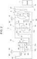
- FIG. 2 schematically shows only the upper half of the torque converter 2 and automatic transmission 3 and does not show the lower half of the torque converter 2 and automatic transmission 3 with respect to the rotation central axes of the torque converter 2 and automatic transmission 3.
- the automatic transmission 3 is provided in the power transmission path between the engine 1 and the drive wheels 7.
- the automatic transmission 3 is configured to change the speed of rotation of an input shaft 3a and then output the rotation to an output shaft 3b.
- the input shaft 3a of the automatic transmission 3 is coupled to the turbine runner 22 of the torque converter 2.
- the output shaft 3b of the automatic transmission 3 is coupled to the drive wheels 7 via the differential unit 6, and the like.
- the automatic transmission 3 includes a first transmission unit (front planetary unit) 31, a second transmission unit (rear planetary unit) 32, first to fourth clutches C1 to C4, a first brake B1, a second brake B2, and the like.
- the first transmission unit 31 is mainly constituted of a first planetary gear 31a.
- the second transmission unit 32 is mainly constituted of a second planetary gear 32a and a third planetary gear 32b.
- the first planetary gear 31a that constitutes the first transmission unit 31 is a double pinion planetary gear set.
- the first planetary gear 31a includes a sun gear S1, a plurality of pairs of mutually meshing pinion gears P1, a planetary carrier CA1 and a ring gear R1.
- the planetary carrier CA1 supports the pinion gears P1 such that each of the pinion gears P1 is rotatable and revolvable.
- the ring gear R1 is in mesh with the sun gear S1 via the pinion gears P1.
- the planetary carrier CA1 is coupled to the input shaft 3a, and rotates integrally with the input shaft 3a.
- the sun gear S1 is fixed to a transmission case 30, and is non-rotatable.
- the ring gear R1 functions as an intermediate output member. The ring gear R1 reduces the speed of rotation from the input shaft 3a and then transmits the rotation reduced in speed to the second transmission unit 32.
- the second planetary gear 32a that constitutes the second transmission unit 32 is a single pinion planetary gear set.
- the second planetary gear 32a includes a sun gear S2, pinion gears P2, a planetary carrier RCA and a ring gear RR.
- the planetary carrier RCA supports the pinion gears P2 such that each of the pinion gears P2 is rotatable and revolvable.
- the ring gear RR is in mesh with the sun gear S2 via the pinion gears P2.
- the third planetary gear 32b that constitutes the second transmission unit 32 is a double pinion planetary gear set.
- the third planetary gear 32b includes a sun gear S3, a plurality of pairs of mutually meshing pinion gears P2, P3, the planetary carrier RCA and the ring gear RR.
- the planetary carrier RCA supports the pinion gears P2, P3 such that each of the pinion gears P2, P3 is rotatable and revolvable.
- the ring gear RR is in mesh with the sun gear S3 via the pinion gears P2, P3.
- the planetary carrier RCA and the ring gear RR are shared between the second planetary gear 32a and the third planetary gear 32b.
- the sun gear S2 is selectively coupled to the transmission case 30 by the first brake B1.
- the sun gear S2 is selectively coupled to the ring gear R1 via the third clutch C3.
- the sun gear S2 is selectively coupled to the planetary carrier CA1 via the fourth clutch C4.
- the sun gear S3 is selectively coupled to the ring gear R1 via the first clutch C1.
- the planetary carrier RCA is selectively coupled to the transmission case 30 by the second brake B2.
- the planetary carrier RCA is selectively coupled to the input shaft 3a via the second clutch C2.
- the ring gear RR is coupled to the output shaft 3b, and rotates integrally with the output shaft 3b.
- Each of the first to fourth clutches C1 to C4, the first brake B1 and the second brake B2 is a frictional engagement element that is frictionally engaged by a hydraulic actuator, and is controlled by the hydraulic pressure control device 4 and the ECU 5.
- FIG. 3 is an operation chart that shows the engaged state or released state of each of the first to fourth clutches C1 to C4, first brake B1 and second brake B2 in each speed position (gear position).
- the circle mark indicates "engaged state
- the blank indicates "released state”.
- a first speed position (1st) is established.
- a speed ratio (Rotation speed of the input shaft 3a/Rotation speed of the output shaft 3b) is the largest.
- a second speed position (2nd) is established.
- a third speed position (3rd) is established.
- a fourth speed position (4th) is established.
- a fifth speed position (5th) is established.
- a sixth speed position (6th) is established.
- a seventh speed position (7th) is established.
- an eighth speed position (8th) is established.
- a reverse position (Rev) is established.
- the forward speed positions (1st to 8th) are established through clutch-to-clutch shift.
- the hydraulic pressure control device 4 controls each of the plurality of frictional engagement elements (the clutches C1 to C4 and the brakes B1, B2) of the automatic transmission 3 such that each frictional engagement element is engaged or released.
- the hydraulic pressure control device 4 has the function of controlling the lockup clutch 24 of the torque converter 2.
- the hydraulic pressure control device 4 includes hydraulic actuators of the frictional engagement elements of the automatic transmission 3, linear solenoid valves, and the like.
- the linear solenoid valves respectively supply control hydraulic pressures to the corresponding hydraulic actuators.
- the ECU 5 is configured to control the operation of the engine 1, the shift of the automatic transmission 3, and the like. Specifically, as shown in FIG. 4 , the ECU 5 includes a CPU 51, a ROM 52, a RAM 53, a backup RAM 54, an input interface 55 and an output interface 56.
- the ECU 5 is an example of an electronic control unit according the aspects of the invention.
- the CPU 51 executes arithmetic processing on the basis of various control programs and maps stored in the ROM 52.
- the ROM 52 stores various control programs, maps, and the like. The maps are referenced when those various control programs are executed.
- the RAM 53 is a memory that temporarily stores computed results of the CPU 51, detected results of sensors, and the like.
- the backup RAM 54 is a nonvolatile memory that stores data, and the like, to be saved at the time when the ignition is turned off.
- a crank position sensor 81, an input shaft rotation speed sensor 82, an output shaft rotation speed sensor 83, an accelerator operation amount sensor 84, a throttle opening degree sensor 85, and the like, are connected to the input interface 55.
- the crank position sensor 81 is provided in order to calculate the rotation speed of the engine 1.
- the input shaft rotation speed sensor 82 is provided in order to calculate the rotation speed of the input shaft 3a (turbine rotation speed) of the automatic transmission 3.
- the output shaft rotation speed sensor 83 is provided in order to calculate the rotation speed of the output shaft 3b of the automatic transmission 3. It is possible to calculate a vehicle speed V on the basis of the rotation speed of the output shaft 3b.
- the accelerator operation amount sensor 84 is provided in order to detect an accelerator operation amount that is the depression amount (operation amount) of an accelerator pedal.
- the throttle opening degree sensor 85 is provided in order to detect the throttle opening degree of the throttle valve.
- An injector 91, an ignitor 92, a throttle motor 93, the hydraulic pressure control device 4, and the like, are connected to the output interface 56.
- the injector 91 is a fuel injection valve, and is able to regulate the fuel injection amount.
- the ignitor 92 is provided in order to regulate the ignition timing of an ignition plug.
- the throttle motor 93 is provided in order to regulate the throttle opening degree of the throttle valve.
- the ECU 5 is configured to be able to control the operation status of the engine 1 by controlling the throttle opening degree, the fuel injection amount, the ignition timing, and the like, on the basis of detected results of the sensors, and the like.
- the ECU 5 is configured to be able to control the shift of the automatic transmission 3 and control the lockup clutch 24 of the torque converter 2 by controlling the hydraulic pressure control device 4.
- a required speed position is set on the basis of a shift map that uses a vehicle speed and an accelerator operation amount as parameters, and the hydraulic pressure control device 4 is controlled such that an actual speed position becomes the required speed position.
- the shift map is a map in which a plurality of regions for obtaining appropriate speed positions (speed positions 1st to 8th that achieve optimal efficiency) are set in response to a vehicle speed and an accelerator operation amount, and is stored in the ROM 52 of the ECU 5.
- a plurality of shift lines for defining the regions are set in the shift map.
- the ECU 5 executes power-on upshift control (torque phase control and inertia phase control) (described later).
- the present embodiment employs a technique for performing a shift with the use of a shift model that determines controlled operation amounts for achieving shift target values as shift control.
- the shift target values are target values of factors (such as a shift time and a driving force) that determine an intended mode of change during shifting.
- the controlled operation amounts are required values of factors (such as an engine torque and a clutch torque) that are operated for controlled objects.
- the relational expression in each of the planetary gears is such a relational expression that a relation in torque among the three members of each of the planetary gears and a relation in the time rate of change in rotation speed each are defined by using the gear ratio of a corresponding one of the planetary gears.
- d ⁇ t/dt is a time derivative, that is, time rate of change, of a turbine rotation speed (rotational angular velocity) ⁇ t (that is, the input shaft rotation speed ⁇ i of the automatic transmission 3), and denotes the acceleration (angular acceleration; hereinafter, referred to as input shaft acceleration) of the input shaft 3a as the amount of change in the speed of the input shaft 3a-side rotating member.
- d ⁇ o/dt is a time rate of change in the output shaft rotation speed ⁇ o of the automatic transmission 3, and denotes an output shaft acceleration.
- Tt denotes a turbine torque, that is, a transmission input torque (hereinafter, also referred to as input torque) Ti, which is the torque of the input shaft 3a as the torque of the input shaft 3a-side rotating member.
- Tt a transmission output torque (hereinafter, also referred to as output torque) that is the torque of the output shaft 3b as the torque of an output shaft 3b-side rotating member.
- Tcapl is the torque capacity (hereinafter, also referred to as engaging clutch torque capacity) of the frictional engagement element that performs engaging operation during shifting.
- Tcdrn is the torque capacity (hereinafter, also referred to as releasing clutch torque capacity) of the frictional engagement element that performs releasing operation during shifting.
- a1, a2, b1, b2, c1, c2, d1, d2 each are a constant at the time when the mathematical expressions (1) and (2) are derived, and are coefficients that are determined by design on the basis of an inertia in each of the rotating elements and the gear ratio of each of the planetary gears. Specific numeric values of these constants depend on, for example, each of types of shift (for example, a shift pattern and a combination of a speed position before shifting and a shift positon after shifting). Therefore, although the equation of motion is one predetermined equation of motion, the equation of motion corresponding to each of the types of shift, in which constants vary depending on each of the types of shift, is used to shift the automatic transmission 3.
- the mathematical expressions (1) and (2) are the equation of motion of the gear train (hereinafter, referred to as the equation of motion) of the automatic transmission 3, and formulate the relation between shift target values and controlled operation amounts.
- Shift target values are allowed to represent a target value of a shift time and a target value of a driving force, and are allowed to be used in the equation of motion.
- three values that is, the turbine torque Tt (which is synonymous with the engine torque Te), the engaging clutch torque capacity Tcapl and the releasing clutch torque capacity Tcdrn, are set as the controlled operation amounts of control (feedback control) for establishing the shift target values. Since there are three controlled operation amounts for the fact that the equation of motion is composed of two mathematical expressions, that is, the mathematical expressions (1) and (2), it is not possible to uniquely determine the controlled operation amounts for achieving the two shift target values.
- torque shares of transmission torque shared between a releasing clutch and an engaging clutch are used as a constraint for obtaining solutions to the equation of motion composed of the mathematical expressions (1) and (2).
- torque shares By using the torque shares as a constraint, it is possible to allow an exchange of torque between the releasing clutch and the engaging clutch (that is, the degree of progress of shift) during shifting to be incorporated into the equation of motion and to uniquely solve the controlled operation amounts.
- the torque shares are the proportions of transmission torque shared between the releasing clutch and the engaging clutch during shifting of the automatic transmission 3 with respect to the torque of the input shaft 3a (input shaft total transmission torque) when the total of transmission torque (total transmission torque) that needs to be shared between both the frictional engagement elements is converted to the input shaft total transmission torque.
- the torque shares are varied in response to the degree of progress of shift during shifting.
- the torque shares are respectively defined by the following mathematical expression (3) and (4) by using a torque share x (for example, 0 ⁇ x ⁇ 1) that varies in time sequence so as to reflect an exchange of torque during shifting.
- the shift model according to the present embodiment is to calculate the controlled operation amounts on the basis of the shift target values by using the equation of motion (the above-described mathematical expressions (1) and (2) of the automatic transmission 3, including the shift target values and the controlled operation amounts, and the relations (the above-described mathematical expressions (3) and (4)) that respectively express the torque shares.
- the shift of the automatic transmission 3 is performed with the use of the shift model.
- the shift model is a predetermined one, and the equation of motion of the gear train having different constants for each of the types of shift (for example, a shift pattern and a combination of a speed position before shifting and a speed position after shifting) as described above is used, so the shift model corresponding to each of the types of shift is used to shift the automatic transmission 3.
- the types of shift for example, a shift pattern and a combination of a speed position before shifting and a speed position after shifting
- the ECU 5 calculates shift target values and controlled operation amounts on the basis of the degree of progress of shift for each shift pattern.
- the shift patterns are, for example, a power-on upshift, a power-off upshift, a power-on downshift and a power-off downshift.
- the shift when hydraulic pressure control is started over the frictional engagement elements commensurate with a target speed position, the shift initially enters the stage of a torque phase in which the shares of a required torque capacity (target clutch torque capacity) between the frictional engagement elements vary, and then passes through the stage of an inertia phase in which the speed ratio of the automatic transmission 3 varies, after which the shift ends. That is, the shift of the automatic transmission 3 proceeds in order of the stage before the torque phase, the stage of the torque phase, the stage of the inertia phase and the stage at the end of the shift.
- target clutch torque capacity target clutch torque capacity
- a map, or the like, in which suitable torque shares that vary as the shift proceeds are set on the basis of the degree of progress of shift for each shift pattern is prepared in advance by experiment, simulation, or the like, and is stored in the ROM 52 of the ECU 5.
- the ECU 5 reads the torque shares based on the degree of progress of shift at the time of shift control, applies the torque shares to the shift model together with the shift target values, and calculates a required input torque of the input shaft 3a (target input shaft torque), an engaging target clutch torque capacity and a releasing target clutch torque capacity, which are the controlled operation amounts.
- the ECU 5 controls the clutch torque capacity of the engaging clutch (the torque capacity of the engaging frictional engagement element) and the clutch torque capacity of the releasing clutch (the torque capacity of the releasing frictional engagement element) in response to a target torque phase progress degree (the degree of progress of a target torque phase) on the basis of the calculated engaging target clutch torque capacity and releasing target clutch torque capacity.
- This control corresponds to torque phase control according to the aspects of the invention.
- the progress of the target torque phase is controlled on the basis of a target output torque, a target torque phase time (a time during which the output torque is changed), the torque shares, and the like.
- the ECU 5 executes inertia phase control after the end of the torque phase control. In the inertia phase control as well, the ECU 5 controls the clutch torque capacity of the engaging clutch and the clutch torque capacity of the releasing clutch in response to the degree of progress of shift on the basis of the engaging target clutch torque capacity and the releasing target clutch torque capacity.
- existing power-on upshift control (hereinafter, referred to as existing control) will be described with reference to FIG. 7 .
- FIG. 7 is a timing chart that shows changes in target clutch torque capacity during power-on upshift.
- the releasing target clutch torque capacity begins to decrease at time t21.
- the engaging target clutch torque capacity begins to increase accordingly. That is, the torque phase starts.
- the inertia phase can start due to a deviation between the target clutch torque capacity and an actual clutch torque capacity, or the like, while the torque phase control is being executed (before the target torque phase progress degree reaches 100%), the torque phase control is continued until the torque phase control completes (until the target torque phase progress degree reaches 100%) even when the inertia phase starts in the existing control (see portion B in FIG. 7 ). For this reason, even when the inertia phase is started, the torque capacity of the engaging clutch is increased to the target clutch torque capacity because of continuation of the torque phase control. Thus, the actual torque capacity of the engaging clutch becomes excessive, and the actual output torque is larger than the target output torque (the dashed line in FIG. 7 ), so a jump-out feeling or a shift shock can be experienced.
- the present embodiment is made in consideration of the above-described inconvenience, and implements control for making it possible to suppress a jump-out feeling and a shift shock even when the inertia phase is started while the torque phase control is being executed at the time of a power-on upshift.
- control power-on upshift control
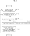
- the control routine of FIG. 5 is repeatedly executed by the ECU 5 at predetermined time intervals.
- step ST101 it is initially determined in step ST101 whether there is a request to shift the automatic transmission 3 and the shift is a power-on upshift.
- negative determination NO
- YES affirmative determination
- step ST102 it is determined whether the torque phase control is being executed. When negative determination is made (NO), the process returns. When affirmative determination (YES) is made in step ST102, the process proceeds to step ST103.
- step ST103 it is determined whether the inertia phase has started.
- the start of the inertia phase is determined at the time when the input shaft rotation speed that is obtained from the output signal of the input shaft rotation speed sensor 82 begins to decrease toward the synchronous rotation speed after shifting.
- step ST103 When negative determination (NO) is made in step ST103 (when the inertia phase has not started), the torque phase control is continued (step ST106).
- step ST103 when affirmative determination (YES) is made in step ST103, that is, when the inertia phase has started, it is determined that the torque phase control has completed, and the torque phase control is ended (step ST104).
- the target torque phase progress degree is set to 100% at this point in time (at the time when the torque phase control is ended) (see portion A in FIG. 6 ).
- step ST105 a torque capacity corresponding to the difference between an actual clutch torque capacity (a clutch torque capacity at the time when the inertia phase has actually started) and the target clutch torque capacity is used as a correction amount, and the correction amount is subtracted from the engaging target clutch torque capacity. This correction process will be described below.
- the difference (absolute value) between the engaging target clutch torque capacity at the time when the inertia phase has started (for example, when the target torque phase progress degree is 80% at the start of the inertia phase, the engaging target clutch torque capacity at the time when the target torque phase progress degree is 80%) and the engaging target clutch torque capacity at the completion of the torque phase control (the engaging target clutch torque capacity in the case where the target torque phase progress degree has reached 100%) is used as a correction amount, and the correction amount is subtracted from the engaging target clutch torque capacity in the inertia phase control (see the hatched portion in FIG. 6 ).
- the engaging target clutch torque capacity does not steeply increase at the time of shifting from the torque phase control to the inertia phase control. Moreover, it is possible to execute subsequent shift control (inertia phase control) while the engaging target clutch torque capacity at the start of the inertia phase (time t12 in FIG. 6 ) is set to the clutch torque capacity at the completion of the torque phase control.
- the difference (absolute value) between the engaging target clutch torque capacity at the start of the inertia phase control and the engaging target clutch torque capacity that is set at the start of the inertia phase control may be set for the correction amount.
- the correction amount for the engaging target clutch torque capacity of the inertia phase control may be set so as to reduce with an elapsed time from the start of the inertia phase or may be set so as to reduce with a decrease in input torque.
- the correction amount may be set so as to reduce with an elapsed time from the start of the inertia phase and a decrease in input torque.
- the correction amount for correcting the engaging target clutch torque capacity in the inertia phase control is set so as to reduce with an elapsed time from the start of the inertia phase or a decrease in input torque, it is possible to further appropriately control the clutch torque capacity of the engaging clutch (frictional engagement element) during the inertia phase control, so it is possible to stably execute the inertia phase control.
- step ST101 to step ST106 in FIG. 5 are executed by the ECU 5, a controller for an automatic transmission according to the aspects of the invention is implemented.
- FIG. 6 is a timing chart that shows changes in target clutch torque capacity at the time of a power-on upshift.
- the releasing target clutch torque capacity begins to decrease at time t11.
- the engaging target clutch torque capacity begins to increase accordingly. That is, the torque phase starts.
- the inertia phase starts.
- the target torque phase progress degree is set to 100% and the torque phase control completes at time t12 at which the inertia phase has started (see portion A in FIG. 6 ).
- the difference (absolute value) between the engaging target clutch torque capacity at the time when the inertia phase has started and the engaging target clutch torque capacity at the time when the torque phase control completes (when the target torque phase progress degree has reached 100%) is used as a correction amount
- the correction amount (see the hatched portion in FIG. 6 ) is subtracted from the engaging target clutch torque capacity in the inertia phase control, and then the inertia phase control is started.
- aspects of the invention are applied to control over the forward eight-speed automatic transmission 3; however, the aspects of the invention are not limited to the control over the automatic transmission 3.
- the aspects of the invention may also be applied to control over an automatic transmission having forward seven-speed or smaller or forward nine-speed or larger.
- the vehicle 100 is an FF vehicle.
- the vehicle may be a front-engine rear-drive (FR) vehicle or a four-wheel drive vehicle.
- the engine 1 is a multi-cylinder gasoline engine; however, the aspects of the invention are not limited to this configuration.
- the engine may be a diesel engine, or the like.
- the ECU 5 may be formed of a plurality of ECUs.
- the aspects of the invention are effectively usable for a controller for a stepped automatic transmission that establishes a plurality of speed positions by selectively engaging a plurality of frictional engagement elements.
Landscapes
- Engineering & Computer Science (AREA)
- General Engineering & Computer Science (AREA)
- Mechanical Engineering (AREA)
- Transportation (AREA)
- Chemical & Material Sciences (AREA)
- Combustion & Propulsion (AREA)
- Physics & Mathematics (AREA)
- Fluid Mechanics (AREA)
- Automation & Control Theory (AREA)
- Control Of Transmission Device (AREA)
Abstract
Description
- The invention relates to a controller for an automatic transmission.
- A clutch-to-clutch shift is performed in a stepped automatic transmission that establishes a plurality of speed positions by selectively engaging a plurality of frictional engagement elements. International Application Publication No.
2013/168225 describes control over an automatic transmission that performs a clutch-to-clutch shift. - In the control described in the International Application Publication No.
2013/168225 , a target torque capacity of an engaging engagement device in a torque phase and an inertia phase is obtained by using an equation common to the torque phase and the inertia phase on the basis of a target input angular acceleration and target output angular acceleration of a transmission and a target torque capacity of a releasing engagement device and a target output torque, and the target torque capacity of the releasing engagement device is set to a value that continuously varies from the torque phase to the inertia phase. - Incidentally, in the control described in the International Application Publication No.
2013/168225 , when the inertia phase begins while torque phase control is being executed during power-on upshift, the torque capacity of the engaging engagement device is increased to a target torque capacity through the torque phase control. For this reason, an actual torque capacity can be excessive, and a jump-out feeling or a shift shock can be experienced. - The invention provides a controller for an automatic transmission, which are able to suppress a jump-out feeling or a shift shock even when an inertia phase begins while torque phase control is being executed during power-on upshift.
- A first aspect of the invention provides a controller for a stepped automatic transmission. The stepped automatic transmission is configured to establish a plurality of speed positions by selectively engaging a plurality of frictional engagement elements. The controller is configured to execute shift control by controlling torque capacities of the frictional engagement elements based on corresponding target torque capacities at the time of a power-on upshift. The controller includes an electronic control unit. The electronic control unit is configured to execute torque phase control for controlling torque capacities of the frictional engagement elements in accordance with a target torque phase progress degree. The electronic control unit is configured to start inertia phase control as the torque phase control completes. The electronic control unit is configured to, when an inertia phase has started while the torque phase control is being executed, end the torque phase control, correct the target torque capacity of an engaging frictional engagement element in the inertia phase control on the basis of a difference between the target torque capacity of the engaging frictional engagement element at the time when the inertia phase has started and the target torque capacity of the engaging frictional engagement element at the time when the torque phase control completes or a difference between the target torque capacity of the engaging frictional engagement element at the time when the inertia phase has started and the target torque capacity of the engaging frictional engagement element, which is set at the time when the inertia phase control starts, and start the inertia phase control.
- In the aspect of the invention, "the torque phase control completes" means the time when the target torque phase progress degree has reached 100%. "The torque phase control is ended" means that the torque phase control is ended before completion of the torque phase control.
- According to the aspect of the invention, when the inertia phase has started while the torque phase control is being executed, the torque phase control is ended, the target torque capacity of the engaging frictional engagement element in the inertia phase control is corrected on the basis of a difference between the target torque capacity of the engaging frictional engagement element at the time when the inertia phase has started and the target torque capacity of the engaging frictional engagement element at the time when the torque phase control completes or a difference between the target torque capacity of the engaging frictional engagement element at the time when the inertia phase has started and the target torque capacity of the engaging frictional engagement element, which is set at the time when the inertia phase control starts, and the inertia phase control is started. With this control, even when the inertia phase has started while the torque phase control is being executed at the time of a power-on upshift, it is possible to shift from the torque phase control to the inertia phase control without an excessive increase in the target torque capacity of the engaging frictional engagement element. Thus, it is possible to suppress a jump-out feeling or a shift shock.
- In the aspect of the invention, the electronic control unit may be configured to reduce a correction amount in accordance with at least one of an elapsed time from when the inertia phase has started and a decrease in input torque of the automatic transmission, and the correction amount may be used to correct the target torque capacity of the engaging frictional engagement element in the inertia phase control. By setting the correction amount in this way, it is possible to further appropriately control the torque capacities during the inertia phase control, so it is possible to stably execute the inertia phase control.
- According to the aspects of the invention, even when the inertia phase has started while the torque phase control is being executed at the time of a power-on upshift, it is possible to shift from the torque phase control to the inertia phase control without an excessive increase in the target torque capacity, so it is possible to suppress a jump-out feeling or a shift shock.
- Features, advantages, and technical and industrial significance of exemplary embodiments of the invention will be described below with reference to the accompanying drawings, in which like numerals denote like elements, and wherein:
-
FIG. 1 is a view that shows the schematic configuration of a vehicle on which an automatic transmission to which the invention is applied is mounted; -
FIG. 2 is a skeletal view that shows the configuration of a torque converter and automatic transmission; -
FIG. 3 is an operation chart that shows the engagement statuses of first to fourth clutches and first and second brakes in each speed position in the automatic transmission; -
FIG. 4 is a block diagram that shows the configuration of a control system of the vehicle; -
FIG. 5 is a flowchart that shows an example of power-on upshift control that is executed by an ECU; -
FIG. 6 is a timing chart that shows an example of the power-on upshift control that is executed by the ECU; and -
FIG. 7 is a timing chart that shows an example of existing power-on upshift control. - Hereinafter, an embodiment of the invention will be described with reference to the accompanying drawings.
- Initially, a
vehicle 100 according to the present embodiment will be described with reference toFIG. 1 to FIG. 4 . - As shown in
FIG. 1 , thevehicle 100 includes anengine 1, atorque converter 2, anautomatic transmission 3, a hydraulicpressure control device 4 and an ECU (an electronic control unit) 5. Thevehicle 100 is of, for example, a front-engine front-drive (FF) type. The output of theengine 1 is transmitted to adifferential unit 6 via thetorque converter 2 and theautomatic transmission 3, and is then distributed to right and left drive wheels (front wheels) 7. - The engine (internal combustion engine) 1 is a driving force source for propelling the
vehicle 100, and is, for example, a multi-cylinder gasoline engine. Theengine 1 is configured such that the operation status is controllable through a throttle opening degree (intake air amount) of a throttle valve, a fuel injection amount, ignition timing, and the like. - As shown in
FIG. 2 , thetorque converter 2 includes apump impeller 21, aturbine runner 22, astator 23 and alockup clutch 24. Thepump impeller 21 is coupled to acrankshaft 1a that is the output shaft of theengine 1. Theturbine runner 22 is coupled to theautomatic transmission 3. Thestator 23 has a torque amplification function. Thelockup clutch 24 is used to directly couple theengine 1 to theautomatic transmission 3.FIG. 2 schematically shows only the upper half of thetorque converter 2 andautomatic transmission 3 and does not show the lower half of thetorque converter 2 andautomatic transmission 3 with respect to the rotation central axes of thetorque converter 2 andautomatic transmission 3. - The
automatic transmission 3 is provided in the power transmission path between theengine 1 and thedrive wheels 7. Theautomatic transmission 3 is configured to change the speed of rotation of aninput shaft 3a and then output the rotation to anoutput shaft 3b. Theinput shaft 3a of theautomatic transmission 3 is coupled to theturbine runner 22 of thetorque converter 2. Theoutput shaft 3b of theautomatic transmission 3 is coupled to thedrive wheels 7 via thedifferential unit 6, and the like. - The
automatic transmission 3 includes a first transmission unit (front planetary unit) 31, a second transmission unit (rear planetary unit) 32, first to fourth clutches C1 to C4, a first brake B1, a second brake B2, and the like. Thefirst transmission unit 31 is mainly constituted of a firstplanetary gear 31a. Thesecond transmission unit 32 is mainly constituted of a secondplanetary gear 32a and a thirdplanetary gear 32b. - The first
planetary gear 31a that constitutes thefirst transmission unit 31 is a double pinion planetary gear set. The firstplanetary gear 31a includes a sun gear S1, a plurality of pairs of mutually meshing pinion gears P1, a planetary carrier CA1 and a ring gear R1. The planetary carrier CA1 supports the pinion gears P1 such that each of the pinion gears P1 is rotatable and revolvable. The ring gear R1 is in mesh with the sun gear S1 via the pinion gears P1. - The planetary carrier CA1 is coupled to the
input shaft 3a, and rotates integrally with theinput shaft 3a. The sun gear S1 is fixed to atransmission case 30, and is non-rotatable. The ring gear R1 functions as an intermediate output member. The ring gear R1 reduces the speed of rotation from theinput shaft 3a and then transmits the rotation reduced in speed to thesecond transmission unit 32. - The second
planetary gear 32a that constitutes thesecond transmission unit 32 is a single pinion planetary gear set. The secondplanetary gear 32a includes a sun gear S2, pinion gears P2, a planetary carrier RCA and a ring gear RR. The planetary carrier RCA supports the pinion gears P2 such that each of the pinion gears P2 is rotatable and revolvable. The ring gear RR is in mesh with the sun gear S2 via the pinion gears P2. - The third
planetary gear 32b that constitutes thesecond transmission unit 32 is a double pinion planetary gear set. The thirdplanetary gear 32b includes a sun gear S3, a plurality of pairs of mutually meshing pinion gears P2, P3, the planetary carrier RCA and the ring gear RR. The planetary carrier RCA supports the pinion gears P2, P3 such that each of the pinion gears P2, P3 is rotatable and revolvable. The ring gear RR is in mesh with the sun gear S3 via the pinion gears P2, P3. The planetary carrier RCA and the ring gear RR are shared between the secondplanetary gear 32a and the thirdplanetary gear 32b. - The sun gear S2 is selectively coupled to the
transmission case 30 by the first brake B1. The sun gear S2 is selectively coupled to the ring gear R1 via the third clutch C3. The sun gear S2 is selectively coupled to the planetary carrier CA1 via the fourth clutch C4. The sun gear S3 is selectively coupled to the ring gear R1 via the first clutch C1. The planetary carrier RCA is selectively coupled to thetransmission case 30 by the second brake B2. The planetary carrier RCA is selectively coupled to theinput shaft 3a via the second clutch C2. The ring gear RR is coupled to theoutput shaft 3b, and rotates integrally with theoutput shaft 3b. - Each of the first to fourth clutches C1 to C4, the first brake B1 and the second brake B2 is a frictional engagement element that is frictionally engaged by a hydraulic actuator, and is controlled by the hydraulic
pressure control device 4 and theECU 5. -
FIG. 3 is an operation chart that shows the engaged state or released state of each of the first to fourth clutches C1 to C4, first brake B1 and second brake B2 in each speed position (gear position). In the operation chart ofFIG. 3 , the circle mark indicates "engaged state, and the blank indicates "released state". - As shown in
FIG. 3 , in theautomatic transmission 3 of this example, when the first clutch C1 and the second brake B2 are engaged, a first speed position (1st) is established. In the first speed position, a speed ratio (Rotation speed of theinput shaft 3a/Rotation speed of theoutput shaft 3b) is the largest. When the first clutch C1 and the first brake B1 are engaged, a second speed position (2nd) is established. - When the first clutch C1 and the third clutch C3 are engaged, a third speed position (3rd) is established. When the first clutch C1 and the fourth clutch C4 are engaged, a fourth speed position (4th) is established.
- When the first clutch C1 and the second clutch C2 are engaged, a fifth speed position (5th) is established. When the second clutch C2 and the fourth clutch C4 are engaged, a sixth speed position (6th) is established.
- When the second clutch C2 and the third clutch C3 are engaged, a seventh speed position (7th) is established. When the second clutch C2 and the first brake B1 are engaged, an eighth speed position (8th) is established. When the third clutch C3 and the second brake B2 are engaged, a reverse position (Rev) is established.
- In the present embodiment, the forward speed positions (1st to 8th) are established through clutch-to-clutch shift.
- The hydraulic
pressure control device 4 controls each of the plurality of frictional engagement elements (the clutches C1 to C4 and the brakes B1, B2) of theautomatic transmission 3 such that each frictional engagement element is engaged or released. The hydraulicpressure control device 4 has the function of controlling thelockup clutch 24 of thetorque converter 2. The hydraulicpressure control device 4 includes hydraulic actuators of the frictional engagement elements of theautomatic transmission 3, linear solenoid valves, and the like. The linear solenoid valves respectively supply control hydraulic pressures to the corresponding hydraulic actuators. - The
ECU 5 is configured to control the operation of theengine 1, the shift of theautomatic transmission 3, and the like. Specifically, as shown inFIG. 4 , theECU 5 includes aCPU 51, aROM 52, aRAM 53, abackup RAM 54, aninput interface 55 and anoutput interface 56. TheECU 5 is an example of an electronic control unit according the aspects of the invention. - The
CPU 51 executes arithmetic processing on the basis of various control programs and maps stored in theROM 52. TheROM 52 stores various control programs, maps, and the like. The maps are referenced when those various control programs are executed. TheRAM 53 is a memory that temporarily stores computed results of theCPU 51, detected results of sensors, and the like. Thebackup RAM 54 is a nonvolatile memory that stores data, and the like, to be saved at the time when the ignition is turned off. - A crank
position sensor 81, an input shaftrotation speed sensor 82, an output shaftrotation speed sensor 83, an acceleratoroperation amount sensor 84, a throttleopening degree sensor 85, and the like, are connected to theinput interface 55. - The crank
position sensor 81 is provided in order to calculate the rotation speed of theengine 1. The input shaftrotation speed sensor 82 is provided in order to calculate the rotation speed of theinput shaft 3a (turbine rotation speed) of theautomatic transmission 3. The output shaftrotation speed sensor 83 is provided in order to calculate the rotation speed of theoutput shaft 3b of theautomatic transmission 3. It is possible to calculate a vehicle speed V on the basis of the rotation speed of theoutput shaft 3b. The acceleratoroperation amount sensor 84 is provided in order to detect an accelerator operation amount that is the depression amount (operation amount) of an accelerator pedal. The throttleopening degree sensor 85 is provided in order to detect the throttle opening degree of the throttle valve. - An
injector 91, anignitor 92, athrottle motor 93, the hydraulicpressure control device 4, and the like, are connected to theoutput interface 56. Theinjector 91 is a fuel injection valve, and is able to regulate the fuel injection amount. Theignitor 92 is provided in order to regulate the ignition timing of an ignition plug. Thethrottle motor 93 is provided in order to regulate the throttle opening degree of the throttle valve. - The
ECU 5 is configured to be able to control the operation status of theengine 1 by controlling the throttle opening degree, the fuel injection amount, the ignition timing, and the like, on the basis of detected results of the sensors, and the like. TheECU 5 is configured to be able to control the shift of theautomatic transmission 3 and control thelockup clutch 24 of thetorque converter 2 by controlling the hydraulicpressure control device 4. - In the shift control by the
ECU 5, for example, a required speed position is set on the basis of a shift map that uses a vehicle speed and an accelerator operation amount as parameters, and the hydraulicpressure control device 4 is controlled such that an actual speed position becomes the required speed position. The shift map is a map in which a plurality of regions for obtaining appropriate speed positions (speed positions 1st to 8th that achieve optimal efficiency) are set in response to a vehicle speed and an accelerator operation amount, and is stored in theROM 52 of theECU 5. A plurality of shift lines for defining the regions (upshift lines and downshift lines for defining the shift regions of 1st to 8th) are set in the shift map. - The
ECU 5 executes power-on upshift control (torque phase control and inertia phase control) (described later). - Before characterized control (power-on upshift control) of the present embodiment is described, the outline of shift control for determining controlled operation amounts that achieve shift target values in the
automatic transmission 3 will be described. - The present embodiment employs a technique for performing a shift with the use of a shift model that determines controlled operation amounts for achieving shift target values as shift control. The shift target values are target values of factors (such as a shift time and a driving force) that determine an intended mode of change during shifting. The controlled operation amounts are required values of factors (such as an engine torque and a clutch torque) that are operated for controlled objects.
- Hereinafter, shift control that uses a shift model will be described. The equation of motion during shifting is expressed by the following mathematical expressions (1) and (2).


- These mathematical expressions (1) and (2) are derived from the equation of motion of each of mutually coupled rotating elements that constitute the
automatic transmission 3 and a relational expression in each of the planetary gears that constitute theautomatic transmission 3. The equation of motion of each of the rotating elements is such an equation of motion that a torque that is expressed by a product of an inertia in each of the rotating elements and a time rate of change in rotation speed is defined as a torque that acts on a member associated with each of the rotating elements among the three members of each of the planetary gears and members at both sides of each of the frictional engagement elements. The relational expression in each of the planetary gears is such a relational expression that a relation in torque among the three members of each of the planetary gears and a relation in the time rate of change in rotation speed each are defined by using the gear ratio of a corresponding one of the planetary gears. - In the mathematical expressions (1) and (2), dωt/dt is a time derivative, that is, time rate of change, of a turbine rotation speed (rotational angular velocity) ωt (that is, the input shaft rotation speed ωi of the automatic transmission 3), and denotes the acceleration (angular acceleration; hereinafter, referred to as input shaft acceleration) of the
input shaft 3a as the amount of change in the speed of theinput shaft 3a-side rotating member. dωo/dt is a time rate of change in the output shaft rotation speed ωo of theautomatic transmission 3, and denotes an output shaft acceleration. Tt denotes a turbine torque, that is, a transmission input torque (hereinafter, also referred to as input torque) Ti, which is the torque of theinput shaft 3a as the torque of theinput shaft 3a-side rotating member. When a torque ratio t of thetorque converter 2 is considered, the turbine torque Tt is synonymous with an engine torque Te (= Tt/t). To denotes a transmission output torque (hereinafter, also referred to as output torque) that is the torque of theoutput shaft 3b as the torque of anoutput shaft 3b-side rotating member. Tcapl is the torque capacity (hereinafter, also referred to as engaging clutch torque capacity) of the frictional engagement element that performs engaging operation during shifting. Tcdrn is the torque capacity (hereinafter, also referred to as releasing clutch torque capacity) of the frictional engagement element that performs releasing operation during shifting. - a1, a2, b1, b2, c1, c2, d1, d2 each are a constant at the time when the mathematical expressions (1) and (2) are derived, and are coefficients that are determined by design on the basis of an inertia in each of the rotating elements and the gear ratio of each of the planetary gears. Specific numeric values of these constants depend on, for example, each of types of shift (for example, a shift pattern and a combination of a speed position before shifting and a shift positon after shifting). Therefore, although the equation of motion is one predetermined equation of motion, the equation of motion corresponding to each of the types of shift, in which constants vary depending on each of the types of shift, is used to shift the
automatic transmission 3. - The mathematical expressions (1) and (2) are the equation of motion of the gear train (hereinafter, referred to as the equation of motion) of the
automatic transmission 3, and formulate the relation between shift target values and controlled operation amounts. Shift target values are allowed to represent a target value of a shift time and a target value of a driving force, and are allowed to be used in the equation of motion. - On the other hand, in the present embodiment, three values, that is, the turbine torque Tt (which is synonymous with the engine torque Te), the engaging clutch torque capacity Tcapl and the releasing clutch torque capacity Tcdrn, are set as the controlled operation amounts of control (feedback control) for establishing the shift target values. Since there are three controlled operation amounts for the fact that the equation of motion is composed of two mathematical expressions, that is, the mathematical expressions (1) and (2), it is not possible to uniquely determine the controlled operation amounts for achieving the two shift target values.
- In the present embodiment, torque shares of transmission torque shared between a releasing clutch and an engaging clutch are used as a constraint for obtaining solutions to the equation of motion composed of the mathematical expressions (1) and (2). By using the torque shares as a constraint, it is possible to allow an exchange of torque between the releasing clutch and the engaging clutch (that is, the degree of progress of shift) during shifting to be incorporated into the equation of motion and to uniquely solve the controlled operation amounts.
- The torque shares are the proportions of transmission torque shared between the releasing clutch and the engaging clutch during shifting of the
automatic transmission 3 with respect to the torque of theinput shaft 3a (input shaft total transmission torque) when the total of transmission torque (total transmission torque) that needs to be shared between both the frictional engagement elements is converted to the input shaft total transmission torque. The torque shares are varied in response to the degree of progress of shift during shifting. - In the present embodiment, where the torque share of the engaging clutch is denoted by xapl and the torque share of the releasing clutch is denoted by xdrn, the torque shares are respectively defined by the following mathematical expression (3) and (4) by using a torque share x (for example, 0 ≤ x ≤ 1) that varies in time sequence so as to reflect an exchange of torque during shifting.


input shaft 3a, and the mathematical expressions (3) and (4). From the mathematical expressions (1) and (2) and the relational expression between Tcapl and Tcdrn, relational expressions for calculating the turbine torque Tt, the engaging clutch torque capacity Tcapl and the releasing clutch torque capacity Tcdrn that are controlled operation amounts are derived. The turbine torque Tt (which is synonymous with the engine torque Te) is expressed by a relational expression that uses "x" (= xapl), "1 - x" (= xdrn), the input shaft acceleration dωt/dt, the transmission output torque To, and the like. Similarly, the engaging clutch torque capacity Tcapl is expressed by a relational expression that uses "x" (= xapl), the input shaft acceleration dωt/dt, the transmission output torque To, and the like. Similarly, the releasing clutch torque capacity Tcdrn is expressed by a relational expression that uses "1 - x" (= xdrn), the input shaft acceleration dωt/dt, the transmission output torque To, and the like. - That is, the shift model according to the present embodiment is to calculate the controlled operation amounts on the basis of the shift target values by using the equation of motion (the above-described mathematical expressions (1) and (2) of the
automatic transmission 3, including the shift target values and the controlled operation amounts, and the relations (the above-described mathematical expressions (3) and (4)) that respectively express the torque shares. In this way, in the present embodiment, by adding the constraint set by the torque share x to the mathematical expressions (1) and (2), the shift of theautomatic transmission 3 is performed with the use of the shift model. Thus, even when there are three controlled operation amounts for two shift target values, it is possible to appropriately determine the three controlled operation amounts with the use of the shift model. - The shift model is a predetermined one, and the equation of motion of the gear train having different constants for each of the types of shift (for example, a shift pattern and a combination of a speed position before shifting and a speed position after shifting) as described above is used, so the shift model corresponding to each of the types of shift is used to shift the
automatic transmission 3. - The
ECU 5 calculates shift target values and controlled operation amounts on the basis of the degree of progress of shift for each shift pattern. The shift patterns are, for example, a power-on upshift, a power-off upshift, a power-on downshift and a power-off downshift. - For example, in the case of a power-on upshift, when hydraulic pressure control is started over the frictional engagement elements commensurate with a target speed position, the shift initially enters the stage of a torque phase in which the shares of a required torque capacity (target clutch torque capacity) between the frictional engagement elements vary, and then passes through the stage of an inertia phase in which the speed ratio of the
automatic transmission 3 varies, after which the shift ends. That is, the shift of theautomatic transmission 3 proceeds in order of the stage before the torque phase, the stage of the torque phase, the stage of the inertia phase and the stage at the end of the shift. - A map, or the like, in which suitable torque shares that vary as the shift proceeds are set on the basis of the degree of progress of shift for each shift pattern is prepared in advance by experiment, simulation, or the like, and is stored in the
ROM 52 of theECU 5. - The
ECU 5 reads the torque shares based on the degree of progress of shift at the time of shift control, applies the torque shares to the shift model together with the shift target values, and calculates a required input torque of theinput shaft 3a (target input shaft torque), an engaging target clutch torque capacity and a releasing target clutch torque capacity, which are the controlled operation amounts. - The
ECU 5 controls the clutch torque capacity of the engaging clutch (the torque capacity of the engaging frictional engagement element) and the clutch torque capacity of the releasing clutch (the torque capacity of the releasing frictional engagement element) in response to a target torque phase progress degree (the degree of progress of a target torque phase) on the basis of the calculated engaging target clutch torque capacity and releasing target clutch torque capacity. This control corresponds to torque phase control according to the aspects of the invention. The progress of the target torque phase is controlled on the basis of a target output torque, a target torque phase time (a time during which the output torque is changed), the torque shares, and the like. TheECU 5 executes inertia phase control after the end of the torque phase control. In the inertia phase control as well, theECU 5 controls the clutch torque capacity of the engaging clutch and the clutch torque capacity of the releasing clutch in response to the degree of progress of shift on the basis of the engaging target clutch torque capacity and the releasing target clutch torque capacity. - Next, the power-on upshift control that is executed by the
ECU 5 will be described. - Initially, existing power-on upshift control (hereinafter, referred to as existing control) will be described with reference to
FIG. 7 . -
FIG. 7 is a timing chart that shows changes in target clutch torque capacity during power-on upshift. In this existing control, after it is determined to perform a power-on upshift, the releasing target clutch torque capacity begins to decrease at time t21. The engaging target clutch torque capacity begins to increase accordingly. That is, the torque phase starts. - In this way, the releasing target clutch torque capacity decreases, and the engaging target clutch torque capacity increases. Then, when torque that is transmitted through the path for which a speed position after shifting is set increases to some extent, the inertia phase starts (time t22).
- Although the inertia phase can start due to a deviation between the target clutch torque capacity and an actual clutch torque capacity, or the like, while the torque phase control is being executed (before the target torque phase progress degree reaches 100%), the torque phase control is continued until the torque phase control completes (until the target torque phase progress degree reaches 100%) even when the inertia phase starts in the existing control (see portion B in
FIG. 7 ). For this reason, even when the inertia phase is started, the torque capacity of the engaging clutch is increased to the target clutch torque capacity because of continuation of the torque phase control. Thus, the actual torque capacity of the engaging clutch becomes excessive, and the actual output torque is larger than the target output torque (the dashed line inFIG. 7 ), so a jump-out feeling or a shift shock can be experienced. - The present embodiment is made in consideration of the above-described inconvenience, and implements control for making it possible to suppress a jump-out feeling and a shift shock even when the inertia phase is started while the torque phase control is being executed at the time of a power-on upshift.
- An example of the control (power-on upshift control) will be described with reference to the flowchart of
FIG. 5 . The control routine ofFIG. 5 is repeatedly executed by theECU 5 at predetermined time intervals. - As the control routine of
FIG. 5 is started, it is initially determined in step ST101 whether there is a request to shift theautomatic transmission 3 and the shift is a power-on upshift. When negative determination (NO) is made, the process returns. When affirmative determination (YES) is made in step ST101, the process proceeds to step ST102. - In step ST102, it is determined whether the torque phase control is being executed. When negative determination is made (NO), the process returns. When affirmative determination (YES) is made in step ST102, the process proceeds to step ST103.
- In step ST103, it is determined whether the inertia phase has started. In determining whether the inertia phase has started, the start of the inertia phase is determined at the time when the input shaft rotation speed that is obtained from the output signal of the input shaft
rotation speed sensor 82 begins to decrease toward the synchronous rotation speed after shifting. - When negative determination (NO) is made in step ST103 (when the inertia phase has not started), the torque phase control is continued (step ST106).
- On the other hand, when affirmative determination (YES) is made in step ST103, that is, when the inertia phase has started, it is determined that the torque phase control has completed, and the torque phase control is ended (step ST104). The target torque phase progress degree is set to 100% at this point in time (at the time when the torque phase control is ended) (see portion A in
FIG. 6 ). - In step ST105, a torque capacity corresponding to the difference between an actual clutch torque capacity (a clutch torque capacity at the time when the inertia phase has actually started) and the target clutch torque capacity is used as a correction amount, and the correction amount is subtracted from the engaging target clutch torque capacity. This correction process will be described below.
- Initially, when the torque phase control is ended and the inertia phase control is started in the case where the inertia phase has started while the torque phase control is being executed, if the engaging target clutch torque capacity in the above-described equation of motion is instantaneously varied at the end of the torque phase (at the start of the inertia phase), the actual engaging clutch torque steeply increases.
- In consideration of such a point, in the present embodiment, the difference (absolute value) between the engaging target clutch torque capacity at the time when the inertia phase has started (for example, when the target torque phase progress degree is 80% at the start of the inertia phase, the engaging target clutch torque capacity at the time when the target torque phase progress degree is 80%) and the engaging target clutch torque capacity at the completion of the torque phase control (the engaging target clutch torque capacity in the case where the target torque phase progress degree has reached 100%) is used as a correction amount, and the correction amount is subtracted from the engaging target clutch torque capacity in the inertia phase control (see the hatched portion in
FIG. 6 ). - With this correction process, the engaging target clutch torque capacity does not steeply increase at the time of shifting from the torque phase control to the inertia phase control. Moreover, it is possible to execute subsequent shift control (inertia phase control) while the engaging target clutch torque capacity at the start of the inertia phase (time t12 in
FIG. 6 ) is set to the clutch torque capacity at the completion of the torque phase control. - As for the correction amount that is subtracted from the engaging target clutch torque capacity, the difference (absolute value) between the engaging target clutch torque capacity at the start of the inertia phase control and the engaging target clutch torque capacity that is set at the start of the inertia phase control may be set for the correction amount.
- The correction amount for the engaging target clutch torque capacity of the inertia phase control may be set so as to reduce with an elapsed time from the start of the inertia phase or may be set so as to reduce with a decrease in input torque. The correction amount may be set so as to reduce with an elapsed time from the start of the inertia phase and a decrease in input torque.
- In this way, when the correction amount for correcting the engaging target clutch torque capacity in the inertia phase control is set so as to reduce with an elapsed time from the start of the inertia phase or a decrease in input torque, it is possible to further appropriately control the clutch torque capacity of the engaging clutch (frictional engagement element) during the inertia phase control, so it is possible to stably execute the inertia phase control.
- When step ST101 to step ST106 in
FIG. 5 are executed by theECU 5, a controller for an automatic transmission according to the aspects of the invention is implemented. - Next, a specific example of the power-on upshift control will be described with reference to
FIG. 6 . -
FIG. 6 is a timing chart that shows changes in target clutch torque capacity at the time of a power-on upshift. In this control example, after it is determined to perform a power-on upshift (it is determined to shift on the basis of a vehicle speed, an accelerator operation amount and the shift map), the releasing target clutch torque capacity begins to decrease at time t11. The engaging target clutch torque capacity begins to increase accordingly. That is, the torque phase starts. - In this way, the releasing target clutch torque capacity decreases, and the engaging target clutch torque capacity increases. When torque that is transmitted through the path for setting a speed position after shifting increases to some extent, the inertia phase starts. When the inertia phase starts while the torque phase control is being executed (when the inertia phase has started while the target torque phase progress degree has not reached 100%), the target torque phase progress degree is set to 100% and the torque phase control completes at time t12 at which the inertia phase has started (see portion A in
FIG. 6 ). - At time t12 at which the inertia phase has started, for example, the difference (absolute value) between the engaging target clutch torque capacity at the time when the inertia phase has started and the engaging target clutch torque capacity at the time when the torque phase control completes (when the target torque phase progress degree has reached 100%) is used as a correction amount, the correction amount (see the hatched portion in
FIG. 6 ) is subtracted from the engaging target clutch torque capacity in the inertia phase control, and then the inertia phase control is started. By correcting the engaging target clutch torque capacity in the inertia phase control in this way, an actual output torque coincides with the target output torque (the dashed line inFIG. 6 ), so it is possible to suppress a jump-out feeling or a shift shock. - As described above, according to the present embodiment, even when the inertia phase has started while the torque phase control is being executed at the time of a power-on upshift, it is possible to shift from the torque phase control to the inertia phase control without an excessive increase in the engaging target clutch torque capacity. Thus, it is possible to suppress a jump-out feeling or a shift shock.
- The embodiment described above is illustrative and not restrictive in all respects. Therefore, the technical scope of the invention should not be interpreted from only the above-described embodiment but be defined on the basis of the appended claims. The technical scope of the invention encompasses the appended claims, equivalents thereof and all the modifications within the scope of the invention.
- For example, in the above-described embodiment, an example in which the aspects of the invention are applied to control over the forward eight-speed
automatic transmission 3 is described; however, the aspects of the invention are not limited to the control over theautomatic transmission 3. The aspects of the invention may also be applied to control over an automatic transmission having forward seven-speed or smaller or forward nine-speed or larger. - In the above-described embodiment, an example in which the
vehicle 100 is an FF vehicle. However, the aspects of the invention are not limited to this configuration. The vehicle may be a front-engine rear-drive (FR) vehicle or a four-wheel drive vehicle. - In the above-described embodiment, an example in which the
engine 1 is a multi-cylinder gasoline engine is described; however, the aspects of the invention are not limited to this configuration. The engine may be a diesel engine, or the like. - In the above-described embodiment, the
ECU 5 may be formed of a plurality of ECUs. - The aspects of the invention are effectively usable for a controller for a stepped automatic transmission that establishes a plurality of speed positions by selectively engaging a plurality of frictional engagement elements.
Claims (2)
- A controller for a stepped automatic transmission (3), the stepped automatic transmission being configured to establish a plurality of speed positions by selectively engaging a plurality of frictional engagement elements (C1 to C4, B1, B2), the controller being configured to execute shift control by controlling torque capacities of the frictional engagement elements based on corresponding target torque capacities at the time of a power-on upshift, the controller characterized by comprising:an electronic control unit (5) configured to:i) execute torque phase control for controlling the torque capacities of the frictional engagement elements in accordance with a target torque phase progress degree,ii) start inertia phase control as the torque phase control completes,iii) when an inertia phase has started while the torque phase control is being executed, end the torque phase control,iv) correct the target torque capacity of an engaging frictional engagement element in the inertia phase control based on a difference between the target torque capacity of the engaging frictional engagement element at the time when the inertia phase has started and the target torque capacity of the engaging frictional engagement element at the time when the torque phase control completes or a difference between the target torque capacity of the engaging frictional engagement element at the time when the inertia phase has started and the target torque capacity of the engaging frictional engagement element, which is set at the time when the inertia phase control starts, andv) start the inertia phase control.
- The controller according to claim 1, characterized in that
the electronic control unit is configured to reduce a correction amount in accordance with at least one of an elapsed time from when the inertia phase has started and a decrease in input torque of the stepped automatic transmission, and the correction amount is used to correct the target torque capacity of the engaging frictional engagement element in the inertia phase control.
Applications Claiming Priority (1)
| Application Number | Priority Date | Filing Date | Title |
|---|---|---|---|
| JP2016148156A JP6423392B2 (en) | 2016-07-28 | 2016-07-28 | Control device for automatic transmission |
Publications (2)
| Publication Number | Publication Date |
|---|---|
| EP3276227A1 true EP3276227A1 (en) | 2018-01-31 |
| EP3276227B1 EP3276227B1 (en) | 2019-08-21 |
Family
ID=59381217
Family Applications (1)
| Application Number | Title | Priority Date | Filing Date |
|---|---|---|---|
| EP17182215.8A Active EP3276227B1 (en) | 2016-07-28 | 2017-07-19 | Controller for automatic transmissions to avoid a shift shock |
Country Status (4)
| Country | Link |
|---|---|
| US (1) | US10132406B2 (en) |
| EP (1) | EP3276227B1 (en) |
| JP (1) | JP6423392B2 (en) |
| CN (1) | CN107664213B (en) |
Cited By (1)
| Publication number | Priority date | Publication date | Assignee | Title |
|---|---|---|---|---|
| US20240190265A1 (en) * | 2022-12-13 | 2024-06-13 | GM Global Technology Operations LLC | Vehicle motion control considering dynamic gear ratio for multi-speed drive systems |
Families Citing this family (1)
| Publication number | Priority date | Publication date | Assignee | Title |
|---|---|---|---|---|
| JP7173060B2 (en) * | 2020-01-17 | 2022-11-16 | トヨタ自動車株式会社 | Vehicle control device |
Citations (3)
| Publication number | Priority date | Publication date | Assignee | Title |
|---|---|---|---|---|
| EP1431624A1 (en) * | 2001-09-28 | 2004-06-23 | JATCO Ltd | Shift control device for automatic transmission |
| US20090248263A1 (en) * | 2008-03-28 | 2009-10-01 | Aisin Aw Co., Ltd. | Shift control apparatus for automatic transmission |
| WO2013168225A1 (en) | 2012-05-08 | 2013-11-14 | トヨタ自動車株式会社 | Shift control device for vehicle |
Family Cites Families (5)
| Publication number | Priority date | Publication date | Assignee | Title |
|---|---|---|---|---|
| JP3425709B2 (en) * | 1997-02-18 | 2003-07-14 | 日産自動車株式会社 | Transmission control device for automatic transmission |
| DE112010005833B4 (en) * | 2010-08-31 | 2022-03-17 | Toyota Jidosha Kabushiki Kaisha | vehicle control device |
| US9790871B2 (en) * | 2012-09-19 | 2017-10-17 | Yamaha Hatsudoki Kabushiki Kaisha | Control apparatus for vehicle, vehicle, and motor |
| CN103671898B (en) * | 2013-12-25 | 2017-06-06 | 盛瑞传动股份有限公司 | A kind of shift control method of hydraulic automatic speed variator |
| JP6225727B2 (en) * | 2014-01-29 | 2017-11-08 | トヨタ自動車株式会社 | Shift control device |
-
2016
- 2016-07-28 JP JP2016148156A patent/JP6423392B2/en active Active
-
2017
- 2017-07-17 CN CN201710581362.8A patent/CN107664213B/en active Active
- 2017-07-19 EP EP17182215.8A patent/EP3276227B1/en active Active
- 2017-07-20 US US15/655,304 patent/US10132406B2/en active Active
Patent Citations (4)
| Publication number | Priority date | Publication date | Assignee | Title |
|---|---|---|---|---|
| EP1431624A1 (en) * | 2001-09-28 | 2004-06-23 | JATCO Ltd | Shift control device for automatic transmission |
| US20090248263A1 (en) * | 2008-03-28 | 2009-10-01 | Aisin Aw Co., Ltd. | Shift control apparatus for automatic transmission |
| WO2013168225A1 (en) | 2012-05-08 | 2013-11-14 | トヨタ自動車株式会社 | Shift control device for vehicle |
| US20150120154A1 (en) * | 2012-05-08 | 2015-04-30 | Toyota Jidosha Kabushiki Kaisha | Speed change control system for vehicles |
Cited By (2)
| Publication number | Priority date | Publication date | Assignee | Title |
|---|---|---|---|---|
| US20240190265A1 (en) * | 2022-12-13 | 2024-06-13 | GM Global Technology Operations LLC | Vehicle motion control considering dynamic gear ratio for multi-speed drive systems |
| US12391129B2 (en) * | 2022-12-13 | 2025-08-19 | GM Global Technology Operations LLC | Vehicle motion control considering dynamic gear ratio for multi-speed drive systems |
Also Published As
| Publication number | Publication date |
|---|---|
| CN107664213B (en) | 2019-09-06 |
| US20180031124A1 (en) | 2018-02-01 |
| JP2018017318A (en) | 2018-02-01 |
| US10132406B2 (en) | 2018-11-20 |
| JP6423392B2 (en) | 2018-11-14 |
| CN107664213A (en) | 2018-02-06 |
| EP3276227B1 (en) | 2019-08-21 |
Similar Documents
| Publication | Publication Date | Title |
|---|---|---|
| KR20150036390A (en) | Vehicle transmission controller | |
| EP3287670B1 (en) | Control device for vehicle, and control method for vehicle | |
| CN103574012B (en) | For controller and the controlling method of vehicle | |
| EP3276227B1 (en) | Controller for automatic transmissions to avoid a shift shock | |
| JP6499129B2 (en) | Vehicle control device | |
| US10161510B2 (en) | Controller for automatic transmission | |
| CN107631021B (en) | Control device for vehicle and the control method for vehicle | |
| JP2018017324A (en) | Control device of vehicle | |
| CN108506478A (en) | Control device and control method for automatic transmission | |
| JP6551329B2 (en) | Control device of automatic transmission | |
| CN107642597B (en) | Control device for automatic transmission | |
| EP3276230B1 (en) | Control device for vehicle and control method for vehicle | |
| CN107642599A (en) | Controller for automatic transmission |
Legal Events
| Date | Code | Title | Description |
|---|---|---|---|
| PUAI | Public reference made under article 153(3) epc to a published international application that has entered the european phase |
Free format text: ORIGINAL CODE: 0009012 |
|
| STAA | Information on the status of an ep patent application or granted ep patent |
Free format text: STATUS: REQUEST FOR EXAMINATION WAS MADE |
|
| 17P | Request for examination filed |
Effective date: 20170819 |
|
| AK | Designated contracting states |
Kind code of ref document: A1 Designated state(s): AL AT BE BG CH CY CZ DE DK EE ES FI FR GB GR HR HU IE IS IT LI LT LU LV MC MK MT NL NO PL PT RO RS SE SI SK SM TR |
|
| AX | Request for extension of the european patent |
Extension state: BA ME |
|
| GRAP | Despatch of communication of intention to grant a patent |
Free format text: ORIGINAL CODE: EPIDOSNIGR1 |
|
| STAA | Information on the status of an ep patent application or granted ep patent |
Free format text: STATUS: GRANT OF PATENT IS INTENDED |
|
| RIC1 | Information provided on ipc code assigned before grant |
Ipc: F16H 61/06 20060101ALI20190130BHEP Ipc: F16H 61/04 20060101ALN20190130BHEP Ipc: F16H 61/08 20060101AFI20190130BHEP |
|
| RIC1 | Information provided on ipc code assigned before grant |
Ipc: F16H 61/04 20060101ALN20190206BHEP Ipc: F16H 61/08 20060101AFI20190206BHEP Ipc: F16H 61/06 20060101ALI20190206BHEP |
|
| INTG | Intention to grant announced |
Effective date: 20190222 |
|
| RIC1 | Information provided on ipc code assigned before grant |
Ipc: F16H 61/06 20060101ALI20190214BHEP Ipc: F16H 61/04 20060101ALN20190214BHEP Ipc: F16H 61/08 20060101AFI20190214BHEP |
|
| GRAS | Grant fee paid |
Free format text: ORIGINAL CODE: EPIDOSNIGR3 |
|
| GRAA | (expected) grant |
Free format text: ORIGINAL CODE: 0009210 |
|
| STAA | Information on the status of an ep patent application or granted ep patent |
Free format text: STATUS: THE PATENT HAS BEEN GRANTED |
|
| AK | Designated contracting states |
Kind code of ref document: B1 Designated state(s): AL AT BE BG CH CY CZ DE DK EE ES FI FR GB GR HR HU IE IS IT LI LT LU LV MC MK MT NL NO PL PT RO RS SE SI SK SM TR |
|
| REG | Reference to a national code |
Ref country code: GB Ref legal event code: FG4D |
|
| REG | Reference to a national code |
Ref country code: CH Ref legal event code: EP |
|
| REG | Reference to a national code |
Ref country code: DE Ref legal event code: R096 Ref document number: 602017006289 Country of ref document: DE |
|
| REG | Reference to a national code |
Ref country code: AT Ref legal event code: REF Ref document number: 1170139 Country of ref document: AT Kind code of ref document: T Effective date: 20190915 |
|
| REG | Reference to a national code |
Ref country code: IE Ref legal event code: FG4D |
|
| REG | Reference to a national code |
Ref country code: DE Ref legal event code: R084 Ref document number: 602017006289 Country of ref document: DE |
|
| REG | Reference to a national code |
Ref country code: GB Ref legal event code: 746 Effective date: 20190924 |
|
| REG | Reference to a national code |
Ref country code: LT Ref legal event code: MG4D |
|
| REG | Reference to a national code |
Ref country code: NL Ref legal event code: MP Effective date: 20190821 |
|
| PG25 | Lapsed in a contracting state [announced via postgrant information from national office to epo] |
Ref country code: NL Free format text: LAPSE BECAUSE OF FAILURE TO SUBMIT A TRANSLATION OF THE DESCRIPTION OR TO PAY THE FEE WITHIN THE PRESCRIBED TIME-LIMIT Effective date: 20190821 Ref country code: HR Free format text: LAPSE BECAUSE OF FAILURE TO SUBMIT A TRANSLATION OF THE DESCRIPTION OR TO PAY THE FEE WITHIN THE PRESCRIBED TIME-LIMIT Effective date: 20190821 Ref country code: NO Free format text: LAPSE BECAUSE OF FAILURE TO SUBMIT A TRANSLATION OF THE DESCRIPTION OR TO PAY THE FEE WITHIN THE PRESCRIBED TIME-LIMIT Effective date: 20191121 Ref country code: LT Free format text: LAPSE BECAUSE OF FAILURE TO SUBMIT A TRANSLATION OF THE DESCRIPTION OR TO PAY THE FEE WITHIN THE PRESCRIBED TIME-LIMIT Effective date: 20190821 Ref country code: PT Free format text: LAPSE BECAUSE OF FAILURE TO SUBMIT A TRANSLATION OF THE DESCRIPTION OR TO PAY THE FEE WITHIN THE PRESCRIBED TIME-LIMIT Effective date: 20191223 Ref country code: FI Free format text: LAPSE BECAUSE OF FAILURE TO SUBMIT A TRANSLATION OF THE DESCRIPTION OR TO PAY THE FEE WITHIN THE PRESCRIBED TIME-LIMIT Effective date: 20190821 Ref country code: SE Free format text: LAPSE BECAUSE OF FAILURE TO SUBMIT A TRANSLATION OF THE DESCRIPTION OR TO PAY THE FEE WITHIN THE PRESCRIBED TIME-LIMIT Effective date: 20190821 Ref country code: BG Free format text: LAPSE BECAUSE OF FAILURE TO SUBMIT A TRANSLATION OF THE DESCRIPTION OR TO PAY THE FEE WITHIN THE PRESCRIBED TIME-LIMIT Effective date: 20191121 |
|
| PG25 | Lapsed in a contracting state [announced via postgrant information from national office to epo] |
Ref country code: LV Free format text: LAPSE BECAUSE OF FAILURE TO SUBMIT A TRANSLATION OF THE DESCRIPTION OR TO PAY THE FEE WITHIN THE PRESCRIBED TIME-LIMIT Effective date: 20190821 Ref country code: RS Free format text: LAPSE BECAUSE OF FAILURE TO SUBMIT A TRANSLATION OF THE DESCRIPTION OR TO PAY THE FEE WITHIN THE PRESCRIBED TIME-LIMIT Effective date: 20190821 Ref country code: GR Free format text: LAPSE BECAUSE OF FAILURE TO SUBMIT A TRANSLATION OF THE DESCRIPTION OR TO PAY THE FEE WITHIN THE PRESCRIBED TIME-LIMIT Effective date: 20191122 Ref country code: ES Free format text: LAPSE BECAUSE OF FAILURE TO SUBMIT A TRANSLATION OF THE DESCRIPTION OR TO PAY THE FEE WITHIN THE PRESCRIBED TIME-LIMIT Effective date: 20190821 Ref country code: AL Free format text: LAPSE BECAUSE OF FAILURE TO SUBMIT A TRANSLATION OF THE DESCRIPTION OR TO PAY THE FEE WITHIN THE PRESCRIBED TIME-LIMIT Effective date: 20190821 Ref country code: IS Free format text: LAPSE BECAUSE OF FAILURE TO SUBMIT A TRANSLATION OF THE DESCRIPTION OR TO PAY THE FEE WITHIN THE PRESCRIBED TIME-LIMIT Effective date: 20191221 |
|
| REG | Reference to a national code |
Ref country code: AT Ref legal event code: MK05 Ref document number: 1170139 Country of ref document: AT Kind code of ref document: T Effective date: 20190821 |
|
| PG25 | Lapsed in a contracting state [announced via postgrant information from national office to epo] |
Ref country code: TR Free format text: LAPSE BECAUSE OF FAILURE TO SUBMIT A TRANSLATION OF THE DESCRIPTION OR TO PAY THE FEE WITHIN THE PRESCRIBED TIME-LIMIT Effective date: 20190821 |
|
| PG25 | Lapsed in a contracting state [announced via postgrant information from national office to epo] |
Ref country code: AT Free format text: LAPSE BECAUSE OF FAILURE TO SUBMIT A TRANSLATION OF THE DESCRIPTION OR TO PAY THE FEE WITHIN THE PRESCRIBED TIME-LIMIT Effective date: 20190821 Ref country code: PL Free format text: LAPSE BECAUSE OF FAILURE TO SUBMIT A TRANSLATION OF THE DESCRIPTION OR TO PAY THE FEE WITHIN THE PRESCRIBED TIME-LIMIT Effective date: 20190821 Ref country code: RO Free format text: LAPSE BECAUSE OF FAILURE TO SUBMIT A TRANSLATION OF THE DESCRIPTION OR TO PAY THE FEE WITHIN THE PRESCRIBED TIME-LIMIT Effective date: 20190821 Ref country code: EE Free format text: LAPSE BECAUSE OF FAILURE TO SUBMIT A TRANSLATION OF THE DESCRIPTION OR TO PAY THE FEE WITHIN THE PRESCRIBED TIME-LIMIT Effective date: 20190821 Ref country code: IT Free format text: LAPSE BECAUSE OF FAILURE TO SUBMIT A TRANSLATION OF THE DESCRIPTION OR TO PAY THE FEE WITHIN THE PRESCRIBED TIME-LIMIT Effective date: 20190821 Ref country code: DK Free format text: LAPSE BECAUSE OF FAILURE TO SUBMIT A TRANSLATION OF THE DESCRIPTION OR TO PAY THE FEE WITHIN THE PRESCRIBED TIME-LIMIT Effective date: 20190821 |
|
| PG25 | Lapsed in a contracting state [announced via postgrant information from national office to epo] |
Ref country code: SM Free format text: LAPSE BECAUSE OF FAILURE TO SUBMIT A TRANSLATION OF THE DESCRIPTION OR TO PAY THE FEE WITHIN THE PRESCRIBED TIME-LIMIT Effective date: 20190821 Ref country code: SK Free format text: LAPSE BECAUSE OF FAILURE TO SUBMIT A TRANSLATION OF THE DESCRIPTION OR TO PAY THE FEE WITHIN THE PRESCRIBED TIME-LIMIT Effective date: 20190821 Ref country code: CZ Free format text: LAPSE BECAUSE OF FAILURE TO SUBMIT A TRANSLATION OF THE DESCRIPTION OR TO PAY THE FEE WITHIN THE PRESCRIBED TIME-LIMIT Effective date: 20190821 Ref country code: IS Free format text: LAPSE BECAUSE OF FAILURE TO SUBMIT A TRANSLATION OF THE DESCRIPTION OR TO PAY THE FEE WITHIN THE PRESCRIBED TIME-LIMIT Effective date: 20200224 |
|
| REG | Reference to a national code |
Ref country code: DE Ref legal event code: R097 Ref document number: 602017006289 Country of ref document: DE |
|
| PLBE | No opposition filed within time limit |
Free format text: ORIGINAL CODE: 0009261 |
|
| STAA | Information on the status of an ep patent application or granted ep patent |
Free format text: STATUS: NO OPPOSITION FILED WITHIN TIME LIMIT |
|
| PG2D | Information on lapse in contracting state deleted |
Ref country code: IS |
|
| 26N | No opposition filed |
Effective date: 20200603 |
|
| PG25 | Lapsed in a contracting state [announced via postgrant information from national office to epo] |
Ref country code: SI Free format text: LAPSE BECAUSE OF FAILURE TO SUBMIT A TRANSLATION OF THE DESCRIPTION OR TO PAY THE FEE WITHIN THE PRESCRIBED TIME-LIMIT Effective date: 20190821 |
|
| PG25 | Lapsed in a contracting state [announced via postgrant information from national office to epo] |
Ref country code: MC Free format text: LAPSE BECAUSE OF FAILURE TO SUBMIT A TRANSLATION OF THE DESCRIPTION OR TO PAY THE FEE WITHIN THE PRESCRIBED TIME-LIMIT Effective date: 20190821 |
|
| REG | Reference to a national code |
Ref country code: CH Ref legal event code: PL |
|
| REG | Reference to a national code |
Ref country code: BE Ref legal event code: MM Effective date: 20200731 |
|
| PG25 | Lapsed in a contracting state [announced via postgrant information from national office to epo] |
Ref country code: LI Free format text: LAPSE BECAUSE OF NON-PAYMENT OF DUE FEES Effective date: 20200731 Ref country code: LU Free format text: LAPSE BECAUSE OF NON-PAYMENT OF DUE FEES Effective date: 20200719 Ref country code: CH Free format text: LAPSE BECAUSE OF NON-PAYMENT OF DUE FEES Effective date: 20200731 |
|
| PG25 | Lapsed in a contracting state [announced via postgrant information from national office to epo] |
Ref country code: BE Free format text: LAPSE BECAUSE OF NON-PAYMENT OF DUE FEES Effective date: 20200731 |
|
| PG25 | Lapsed in a contracting state [announced via postgrant information from national office to epo] |
Ref country code: IE Free format text: LAPSE BECAUSE OF NON-PAYMENT OF DUE FEES Effective date: 20200719 |
|
| PG25 | Lapsed in a contracting state [announced via postgrant information from national office to epo] |
Ref country code: MT Free format text: LAPSE BECAUSE OF FAILURE TO SUBMIT A TRANSLATION OF THE DESCRIPTION OR TO PAY THE FEE WITHIN THE PRESCRIBED TIME-LIMIT Effective date: 20190821 Ref country code: CY Free format text: LAPSE BECAUSE OF FAILURE TO SUBMIT A TRANSLATION OF THE DESCRIPTION OR TO PAY THE FEE WITHIN THE PRESCRIBED TIME-LIMIT Effective date: 20190821 |
|
| PG25 | Lapsed in a contracting state [announced via postgrant information from national office to epo] |
Ref country code: MK Free format text: LAPSE BECAUSE OF FAILURE TO SUBMIT A TRANSLATION OF THE DESCRIPTION OR TO PAY THE FEE WITHIN THE PRESCRIBED TIME-LIMIT Effective date: 20190821 |
|
| PGFP | Annual fee paid to national office [announced via postgrant information from national office to epo] |
Ref country code: GB Payment date: 20220526 Year of fee payment: 6 Ref country code: FR Payment date: 20220510 Year of fee payment: 6 |
|
| PGFP | Annual fee paid to national office [announced via postgrant information from national office to epo] |
Ref country code: DE Payment date: 20220524 Year of fee payment: 6 |
|
| P01 | Opt-out of the competence of the unified patent court (upc) registered |
Effective date: 20230427 |
|
| REG | Reference to a national code |
Ref country code: DE Ref legal event code: R119 Ref document number: 602017006289 Country of ref document: DE |
|
| GBPC | Gb: european patent ceased through non-payment of renewal fee |
Effective date: 20230719 |
|
| PG25 | Lapsed in a contracting state [announced via postgrant information from national office to epo] |
Ref country code: DE Free format text: LAPSE BECAUSE OF NON-PAYMENT OF DUE FEES Effective date: 20240201 Ref country code: GB Free format text: LAPSE BECAUSE OF NON-PAYMENT OF DUE FEES Effective date: 20230719 |
|
| PG25 | Lapsed in a contracting state [announced via postgrant information from national office to epo] |
Ref country code: FR Free format text: LAPSE BECAUSE OF NON-PAYMENT OF DUE FEES Effective date: 20230731 |