EP3276180A1 - Pump - Google Patents
Pump Download PDFInfo
- Publication number
- EP3276180A1 EP3276180A1 EP16768797.9A EP16768797A EP3276180A1 EP 3276180 A1 EP3276180 A1 EP 3276180A1 EP 16768797 A EP16768797 A EP 16768797A EP 3276180 A1 EP3276180 A1 EP 3276180A1
- Authority
- EP
- European Patent Office
- Prior art keywords
- balance
- pump
- space
- rotating shaft
- casing
- Prior art date
- Legal status (The legal status is an assumption and is not a legal conclusion. Google has not performed a legal analysis and makes no representation as to the accuracy of the status listed.)
- Granted
Links
Images


Classifications
-
- B—PERFORMING OPERATIONS; TRANSPORTING
- B01—PHYSICAL OR CHEMICAL PROCESSES OR APPARATUS IN GENERAL
- B01D—SEPARATION
- B01D61/00—Processes of separation using semi-permeable membranes, e.g. dialysis, osmosis or ultrafiltration; Apparatus, accessories or auxiliary operations specially adapted therefor
- B01D61/02—Reverse osmosis; Hyperfiltration ; Nanofiltration
- B01D61/10—Accessories; Auxiliary operations
-
- F—MECHANICAL ENGINEERING; LIGHTING; HEATING; WEAPONS; BLASTING
- F04—POSITIVE - DISPLACEMENT MACHINES FOR LIQUIDS; PUMPS FOR LIQUIDS OR ELASTIC FLUIDS
- F04D—NON-POSITIVE-DISPLACEMENT PUMPS
- F04D1/00—Radial-flow pumps, e.g. centrifugal pumps; Helico-centrifugal pumps
- F04D1/06—Multi-stage pumps
-
- F—MECHANICAL ENGINEERING; LIGHTING; HEATING; WEAPONS; BLASTING
- F04—POSITIVE - DISPLACEMENT MACHINES FOR LIQUIDS; PUMPS FOR LIQUIDS OR ELASTIC FLUIDS
- F04D—NON-POSITIVE-DISPLACEMENT PUMPS
- F04D15/00—Control, e.g. regulation, of pumps, pumping installations or systems
- F04D15/0005—Control, e.g. regulation, of pumps, pumping installations or systems by using valves
- F04D15/0011—Control, e.g. regulation, of pumps, pumping installations or systems by using valves by-pass valves
-
- F—MECHANICAL ENGINEERING; LIGHTING; HEATING; WEAPONS; BLASTING
- F04—POSITIVE - DISPLACEMENT MACHINES FOR LIQUIDS; PUMPS FOR LIQUIDS OR ELASTIC FLUIDS
- F04D—NON-POSITIVE-DISPLACEMENT PUMPS
- F04D15/00—Control, e.g. regulation, of pumps, pumping installations or systems
- F04D15/0077—Safety measures
- F04D15/0083—Protection against sudden pressure change, e.g. check valves
-
- F—MECHANICAL ENGINEERING; LIGHTING; HEATING; WEAPONS; BLASTING
- F04—POSITIVE - DISPLACEMENT MACHINES FOR LIQUIDS; PUMPS FOR LIQUIDS OR ELASTIC FLUIDS
- F04D—NON-POSITIVE-DISPLACEMENT PUMPS
- F04D29/00—Details, component parts, or accessories
- F04D29/04—Shafts or bearings, or assemblies thereof
- F04D29/041—Axial thrust balancing
- F04D29/0416—Axial thrust balancing balancing pistons
Definitions
- the present invention relates to a pump.
- a multistage pump which is one form of a pump, has a plurality of impellers fixed on a rotating shaft.
- a liquid is introduced into a pump casing from a suction port of the multistage pump.
- the liquid introduced in the pump casing is sequentially pressurized by the impellers and discharged from a discharge port.
- Multistage pumps are used for transferring a variety of liquid, such as fresh water and sea water, and are used in various sites.
- Axial thrust acts on the rotating shaft of a multistage pump from the discharge side to the suction side due to the pressure difference between the suction side and the discharge side of the rotating impellers. Therefore, the multistage pump is provided with a balance mechanism that produces balance thrust in the opposite direction to the axial thrust in order to balance the axial thrust and the balance thrust.
- the balance mechanism includes a balance disk mounted on the rotating shaft, and a balance seat attached to the pump casing and facing the balance disk.
- a balance space accommodating the balance disk and the balance seat is in communication with a space on the fluid suction side of the pump casing by a balance pipe.
- PTL 1 discloses a multistage pump provided with such a balance mechanism.
- the complex shape of the impellers of multiple stages provides a conduit resistance. Therefore, the pressure on the suction side is reduced by the conduit resistance of multiple stages of impellers and applied to the balance disk.
- This pressure acts on the balance disk as the pressure in the same direction as the balance thrust. Consequently, a larger pressure in the axial thrust direction than the pressure in the balance thrust direction is applied to the balance disk.
- the balance disk is pushed toward the balance seat, and the balance disk and the balance seat may come into contact with each other.
- the balance disk and the balance seat may be in contact for a long time until the discharge pressure is stabilized, and the contact portions may be damaged.
- PTL 2 discloses an idea for avoiding contact between the balance disk and the balance seat of a multistage pump.
- a pressure switch is installed in a discharge line of the multistage pump, and an electromagnetic valve is installed in a balance pipe.
- PTL 2 controls the electromagnetic valve to be opened when the discharge pressure of the multistage pump becomes higher than the suction pressure by a set value or more, and controls the electromagnetic valve to be closed when the discharge pressure becomes lower than the set value at the time the pump is stopped. Since the technique disclosed in the cited literature 2 uses the pressure switch and the electromagnetic valve, electrical wiring work is required and the device configuration is complicated. Moreover, there are possibilities that an electromagnetic coil is burned out, and that the size and cost of the electromagnetic valve main body are increased depending on the specification of liquid.
- PTL 3 discloses a technique that provides a plurality of grooves in a balance disk in order to prevent the balance disk and a stationary member on the pump casing side from being damaged by unstable pump pressure at the time of starting the pump and so on.
- this technique makes the processing of the balance disk complicated.
- a pump of one embodiment includes: a rotating shaft; an impeller mounted on the rotating shaft; a balance mechanism for balancing axial thrust acting on the rotating shaft; a pump casing accommodating the impeller and the balance mechanism; a balance pipe for allowing communication between a balance space in the pump casing where the balance mechanism is accommodated and a space on a fluid suction side of the pump casing; and a check valve provided in the balance pipe to allow fluid to flow through the check valve in only a direction from the balance space toward the space on the fluid suction side.
- the pump of one embodiment may further include a safety valve provided between the balance space and the check valve to release a fluid having a pressure equal to or higher than a set value to outside.
- the balance mechanism may include a balance disk mounted on the rotating shaft, and a balance seat attached to the pump casing and facing the balance disk.
- the pump may be a pump capable of being driven so that a rotational speed of the rotating shaft is gradually increased by an inverter when starting the pump.
- the pump may be a pump for pressure-feeding a fluid to flow through a reverse osmosis membrane provided on the discharge side of the pump.
- Fig. 1A is a side view of a multistage pump of one embodiment.
- Fig. 1B is a view of the multistage pump of one embodiment as seen from the direction indicated by the arrow A in Fig. 1A.
- Fig. 1C is a view of the multistage pump of one embodiment as seen from the direction indicated by the arrow B in Fig. 1A .
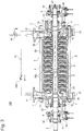
- Fig. 2 is a cross-sectional view of the multistage pump of one embodiment.
- the multistage pump of this embodiment may be used, for example, as a pump for pressure-feeding a fluid (seawater) to flow through a reverse osmosis (RO) membrane provided on the discharge side of the multistage pump in a seawater desalination system, but is not limited to this usage.
- a multistage pump including a plurality of impellers is described as an example, but the present invention is not limited to this.
- a multistage pump 200 includes a rotating shaft 1 extending in a predetermined direction, a plurality of impellers 2 fixed on the rotating shaft 1, and a pump casing 3 accommodating the impellers 2.
- the rotating shaft 1 is rotatably supported by a bearing 9.
- One end of the rotating shaft 1 is connected to a driving source such as a motor.
- the rotating shaft 1 and the impellers 2 are driven rotationally by the driving source.
- the pump casing 3 includes a suction casing 10 in which a suction port 11 is formed, a discharge casing 30 in which a discharge port 31 is formed, and an intermediate casing 50 placed between the suction casing 10 and the discharge casing 30.
- a leg part 80 is mounted on the suction casing 10.
- a leg part 81 is mounted on the discharge casing 30.
- the intermediate casing 50 has a structure in which a plurality of annular casing pieces 50a are stacked in the axial direction.
- a guide vane 4 is arranged on the outside of each impeller 2 in a radial direction.
- One set of the impeller 2 and guide vane 4 are placed in each casing piece 50a.
- the suction casing 10, the intermediate casing 50 and the discharge casing 30 are fastened to each other with through bolts 6 and nuts 7.
- the suction casing 10 and the discharge casing 30 are detachably attached to the intermediate casing 50. In other words, it is possible to separate the suction casing 10 and the discharge casing 30 from the intermediate casing 50 by removing the through bolts 6 and the nuts 7.
- the multistage pump 200 allows a change in the number of stages of the impellers 2. In the case when the number of stages of the impellers 2 is to be increased, a desired number of impellers and the guide vanes and casing pieces corresponding to these impellers are added to the multistage pump 200. On the other hand, in the case when the number of stages of the impellers 2 is to be decreased, a desired number of impellers and the guide vanes and casing pieces corresponding to these impellers are removed from the multistage pump 200. Thus, the multistage pump 200 may have a desired number of stages according to the application.
- the rotating shaft 1 extends through the suction casing 10 and the discharge casing 30.
- Each section of the suction casing 10 and the discharge casing 30 where the rotating shaft 1 pierces through is provided with a shaft sealing mechanism 55.
- a mechanical seal or gland packing is used for the shaft sealing mechanism 55.
- Each bearing 9 is housed in a bearing casing 65.
- a bearing cover 67 is fixed to each bearing casing 65 with a bolt.
- Lubricating oil is filled in each bearing casing 65. This lubricating oil is cooled by a cooling pipe 66. Note that the cooling pipe 66 may not be provided.
- a suction volute 20 Formed in the suction casing 10 are a suction volute 20 connected to the suction port 11, and a side chamber 25 adjacent to the first-stage impeller among the multiple stages of impellers 2. A part of liquid whose pressure is increased by the first-stage impeller flows into the side chamber 25.
- the suction volute 20 and the side chamber 25 are separated by a partition wall 26.
- the multistage pump 200 has a balance mechanism 70.
- the balance mechanism 70 is placed in the balance space 73 inside the discharge casing 30.
- the balance mechanism 70 includes a balance disk 71 which is mounted on the rotating shaft 1 and rotates integrally with the rotating shaft 1.
- the balance mechanism 70 also includes a balance seat 72 which is mounted on the discharge casing 30 and arranged to face the liquid inflow side of the balance disk 71.
- the balance mechanism 70 has the function of balancing the thrust force acting on the rotating shaft 1 by supporting the thrust force produced due to the pressure difference between the suction side and the discharge side of the impellers 2.
- the liquid whose pressure is increased by the impellers 2 passes through a minute gap between the balance disk 71 and the balance seat 72 and flows into the balance space 73.
- the multistage pump 200 of this embodiment is explained by describing the balance mechanism 70 including the balance disk 71 and the balance seat 72 as an example, but the present invention is not limited to this.
- the present invention is applicable to a pump equipped with other well-known balance mechanism that balances axial thrust and balance thrust by producing balance thrust in the opposite direction to the axial thrust of the rotating shaft.
- the multistage pump 200 includes a balance pipe 75.
- the balance pipe 75 allows communication between the balance space 73 and the space inside the suction casing 10.
- the space in the suction casing 10 is, for example, the suction port 11, the suction volute 20, or the side chamber 25.
- the multistage pump 200 of this embodiment does not employ an external balance system that returns the fluid in the balance space 73 to a part other than the multistage pump 200, such as a deaerator, for example, but employs a self-balance system that returns the fluid in the balance space 73 to the multistage pump 200.
- the multistage pump 200 includes a check valve 100 provided in the balance pipe 75.
- the check valve 100 is a valve that allows the fluid to flow through the valve in only a direction from the balance space 73 to the space on the fluid suction side.
- the check valve 100 is a valve that allows the fluid in the balance pipe 75 to flow in only a direction from the balance space 73 to the space in the suction casing 10.
- the pressure loss at the check valve 100 causes an increase in the pressure in the balance space 73.
- the pressure increase in the balance space 73 decreases the distance between the balance disk 71 and the balance seat 72, and may cause contact between the balance disk 71 and the balance seat 72. Therefore, a valve that provides no resistance to the pressure and flow rate in the balance space 73 during operation of the multistage pump 200 is selected for the check valve 100.
- the multistage pump 200 of this embodiment it is possible to realize a simple structure capable of suppressing contact between the balance disk 71 and the balance seat 72. Specifically, in the case where water is flowed in the multistage pump 200 by another pump or the like while the multistage pump 200 is stopped, the pressure on the suction side is reduced by the conduit resistance of the multiple stages of impellers 2 when the water flows in the multistage pump 200, and the reduced pressure is applied to the balance space 73.
- the multistage pump 200 of this embodiment is provided with the check valve 100, the fluid is prevented from flowing from the space in the suction casing 10 into the balance space 73 through the balance pipe 75. As a result, only the thrust in the F1 direction is applied to the balance disk 71, and thus it is possible to prevent contact between the opposing surfaces of the balance disk 71 and balance seat 72.
- the multistage pump 200 of this embodiment may be driven so that the rotational speed gradually increases and the discharge pressure rises gradually by using an inverter etc. when starting the multistage pump 200.
- the check valve 100 in a period in which the output frequency of the inverter is low and the pressure in the discharge port 31 is low, since the pressure in the balance space 73 is lower than the pressure in the space in the suction casing 10, the check valve 100 remains closed. Consequently, the movement of fluid between the balance space 73 and the space in the suction casing 10 through the balance pipe 75 is restricted. While the check valve 100 is closed, only thrust in the F1 direction is applied to the balance disk 71 without thrust in the F2 direction. Therefore, it is possible to suppress contact between the opposing surfaces of the rotating balance disk 71 and the stationary balance seat 72.
- the multistage pump 200 When the multistage pump 200 is operated by a rated operation and the discharge pressure is stabilized, the pressure on the discharge side rises and the pressure in the balance space 73 becomes higher than that in the space in the suction casing 10. Consequently, the check valve 100 is opened, and the balance space 73 and the space in the suction casing 10 become in communication through the balance pipe 75. As a result, the pressure in the balance space 73 and the pressure in the space in the suction casing 10 become substantially the same, thereby balancing the rotating shaft 1.
- the multistage pump 200 of this embodiment has a safety valve 110 that releases fluid to the outside when the pressure of the fluid becomes equal to or higher than a set value.
- the safety valve 110 is provided between the balance space 73 and the check valve 100. More specifically, the safety valve 110 is provided between the balance space 73 of the balance pipe 75 and the check valve 100.
- the multistage pump 200 of this embodiment has the safety valve 110 provided between the balance space 73 and the check valve 100 in order to avoid an increase in pressure in the balance space 73.
- FIG. 2 is explained by describing the multistage pump 200 having the balance mechanism 70 including the balance disk 71 and the balance seat 72 as an example, but the present invention is not limited to this.
- Fig. 3 is a cross-sectional view of a multistage pump of one embodiment.
- a multistage pump 300 shown in Fig. 3 has a balance mechanism with a balance piston.
- parts having functions similar to those of the multistage pump 200 of Fig. 2 are denoted with the same reference numerals as in Fig. 2 , and explanations thereof are omitted.
- the multistage pump 300 has a balance mechanism 360.
- the balance mechanism 360 is placed in a balance space 362 inside a discharge casing 30.
- the balance mechanism 360 includes a balance piston 320 which is mounted on the rotating shaft 1 and rotates integrally with the rotating shaft 1.
- the balance mechanism 360 also includes a balance bushing 310 which is attached to the discharge casing 30 and arranged to face the outer peripheral surface of the balance piston 320.
- the balance mechanism 360 has the function of balancing the thrust force acting on the rotating shaft 1 by supporting the thrust force produced due to the difference in pressure between the suction side and the discharge side of the impellers 2.
- the liquid pressurized by the impellers 2 passes through a minute gap between the balance piston 320 and the balance bushing 310 and flows into the balance space 362.
- the multistage pump 300 has a slide bearing 370 that rotatably supports the rotating shaft 1.
- the slide bearing 370 includes a thrust disk 340 mounted on the rotating shaft 1 and rotating integrally with the rotating shaft 1, and a thrust seat 330 placed to face the liquid inflow side of the thrust disk 340. While the multistage pump 300 is in operation, oil is supplied to the slide bearing 370 through an oil supply port 350.
- the slide bearing 370 supports the thrust force acting on the rotating shaft 1 by contact between the thrust disk 340 and the thrust seat 330 while the multistage pump 300 is in operation.
- the multistage pump 300 of this embodiment it is possible to realize a simple structure capable of suppressing contact between the thrust disk 340 and the thrust seat 330.
- the pressure on the suction side is reduced by the conduit resistance of multiple stages of impellers 2 when the water flows inside the multistage pump 300, and the reduced pressure is applied to the surface on one side of the balance piston 320.
- the check valve 100 focusing on the flow of fluid through the balance pipe 75, if the check valve 100 is not provided, the pressure on the suction side is applied to the other surface of the balance piston 320 through the balance pipe without substantially no conduit resistance because of the simple shape of the balance pipe 75.
- the balance piston 320 and the rotating shaft 1 are pushed in the same direction as the axial thrust due to the difference in pressure applied to the balance piston 320.
- the thrust disk 340 is pushed toward the thrust seat 330, and there is a risk that the thrust disk 340 and the thrust seat 330 may come into contact with each other.
- the multistage pump 300 is started while the thrust disk 340 and the thrust seat 330 are in contact with each other, there is a risk of seizure of the thrust disk 340 and the thrust seat 330 due to inadequate formation of an oil film on the slide bearing 370.
- the multistage pump 300 of this embodiment is provided with the check valve 100, the flow of fluid from the space in the suction casing 10 to the balance space 362 through the balance pipe 75 is prevented. Consequently, only thrust in the direction opposite to the axial thrust is applied to the balance piston 320 and the rotating shaft 1. As a result, since it is possible to prevent contact between the thrust disk 340 and the thrust seat 330, seizure of the thrust disk 340 and the thrust seat 330 is avoided.
Landscapes
- Engineering & Computer Science (AREA)
- Mechanical Engineering (AREA)
- General Engineering & Computer Science (AREA)
- Chemical & Material Sciences (AREA)
- Water Supply & Treatment (AREA)
- Nanotechnology (AREA)
- Chemical Kinetics & Catalysis (AREA)
- Control Of Non-Positive-Displacement Pumps (AREA)
- Structures Of Non-Positive Displacement Pumps (AREA)
- Separation Using Semi-Permeable Membranes (AREA)
Abstract
Description
- The present invention relates to a pump.
- A multistage pump, which is one form of a pump, has a plurality of impellers fixed on a rotating shaft. A liquid is introduced into a pump casing from a suction port of the multistage pump. The liquid introduced in the pump casing is sequentially pressurized by the impellers and discharged from a discharge port. Multistage pumps are used for transferring a variety of liquid, such as fresh water and sea water, and are used in various sites.
- Axial thrust acts on the rotating shaft of a multistage pump from the discharge side to the suction side due to the pressure difference between the suction side and the discharge side of the rotating impellers. Therefore, the multistage pump is provided with a balance mechanism that produces balance thrust in the opposite direction to the axial thrust in order to balance the axial thrust and the balance thrust.
- The balance mechanism includes a balance disk mounted on the rotating shaft, and a balance seat attached to the pump casing and facing the balance disk. A balance space accommodating the balance disk and the balance seat is in communication with a space on the fluid suction side of the pump casing by a balance pipe.
- By providing the balancing function, the balance thrust in the opposite direction to the axial thrust acts on the balance disk. As a result, the axial thrust and the balance thrust are balanced, and the axial thrust is canceled out. PTL 1 discloses a multistage pump provided with such a balance mechanism.
-
- PTL 1: Japanese Patent Laid-Open No.
2000-130400 - PTL 2: Japanese Utility Model Laid-Open No.
62-148797 - PTL 3: Japanese Patent Laid-Open No.
11-294375 - However, the prior art does not consider realizing a pump with a simple structure capable of suppressing contact between the balance disk and the balance seat.
- In other words, even if multistage-pump facilities are stopped at night and when on holidays, conventional multistage pumps are not stopped and are kept operating in order to avoid pressure fluctuation at the time of start and stop. However, in recent years, from the energy saving point of view, the multistage pumps are stopped at an increasing number of sites.
- Here, there is a case where a device that is incapable of coping with a sudden pressure change is connected to the discharge side of a multistage pump. In this case, in order to avoid a sudden discharge-pressure increase at startup, water is flowed into the multistage pump by another pump while the multistage pump is stopped, and the discharge pressure is gradually increased by accelerating the speed slowly by an inverter etc. at the time of starting the multistage pump.
- If water is flowed while the multistage pump is stopped, since the balance pipe has a simple shape, the pressure on the suction side is applied to the balance disk through the balance pipe without substantially no conduit resistance. This pressure acts on the balance disk as the pressure in the same direction as the axial thrust.
- On the other hand, in the multistage pump being stopped, the complex shape of the impellers of multiple stages provides a conduit resistance. Therefore, the pressure on the suction side is reduced by the conduit resistance of multiple stages of impellers and applied to the balance disk. This pressure acts on the balance disk as the pressure in the same direction as the balance thrust. Consequently, a larger pressure in the axial thrust direction than the pressure in the balance thrust direction is applied to the balance disk. As a result, the balance disk is pushed toward the balance seat, and the balance disk and the balance seat may come into contact with each other.
- If the multistage pump is started in a state in which the balance disk and the balance seat are in contact with each other, the balance disk and the balance seat may be in contact for a long time until the discharge pressure is stabilized, and the contact portions may be damaged.
- On the other hand,
PTL 2 discloses an idea for avoiding contact between the balance disk and the balance seat of a multistage pump. In the citedliterature 2, a pressure switch is installed in a discharge line of the multistage pump, and an electromagnetic valve is installed in a balance pipe.PTL 2 controls the electromagnetic valve to be opened when the discharge pressure of the multistage pump becomes higher than the suction pressure by a set value or more, and controls the electromagnetic valve to be closed when the discharge pressure becomes lower than the set value at the time the pump is stopped. Since the technique disclosed in the citedliterature 2 uses the pressure switch and the electromagnetic valve, electrical wiring work is required and the device configuration is complicated. Moreover, there are possibilities that an electromagnetic coil is burned out, and that the size and cost of the electromagnetic valve main body are increased depending on the specification of liquid. -
PTL 3 discloses a technique that provides a plurality of grooves in a balance disk in order to prevent the balance disk and a stationary member on the pump casing side from being damaged by unstable pump pressure at the time of starting the pump and so on. However, this technique makes the processing of the balance disk complicated. - It is therefore an objective of the present invention to realize a pump with a simple structure capable of suppressing contact between a balance disk and a balance seat.
- A pump of one embodiment includes: a rotating shaft; an impeller mounted on the rotating shaft; a balance mechanism for balancing axial thrust acting on the rotating shaft; a pump casing accommodating the impeller and the balance mechanism; a balance pipe for allowing communication between a balance space in the pump casing where the balance mechanism is accommodated and a space on a fluid suction side of the pump casing; and a check valve provided in the balance pipe to allow fluid to flow through the check valve in only a direction from the balance space toward the space on the fluid suction side.
- The pump of one embodiment may further include a safety valve provided between the balance space and the check valve to release a fluid having a pressure equal to or higher than a set value to outside.
- In the pump of one embodiment, the balance mechanism may include a balance disk mounted on the rotating shaft, and a balance seat attached to the pump casing and facing the balance disk.
- In the pump of one embodiment, the pump may be a pump capable of being driven so that a rotational speed of the rotating shaft is gradually increased by an inverter when starting the pump.
- In the pump of one embodiment, the pump may be a pump for pressure-feeding a fluid to flow through a reverse osmosis membrane provided on the discharge side of the pump.
-
- [
Fig. 1A] Fig. 1A is a side view of a multistage pump of one embodiment. - [
Fig. 1B] Fig. 1B is a view of the multistage pump of one embodiment as seen from a direction indicated by an arrow A inFig. 1A . - [
Fig. 1C] Fig. 1C is a view of the multistage pump of one embodiment as seen from a direction indicated by an arrow B inFig. 1A . - [
Fig. 2] Fig. 2 is a cross-sectional view of the multistage pump of one embodiment. - [
Fig. 3] Fig. 3 is a cross-sectional view of a multistage pump of one embodiment. - The following will describe a pump of an embodiment of the present invention with reference to the drawings.
-
Fig. 1A is a side view of a multistage pump of one embodiment.Fig. 1B is a view of the multistage pump of one embodiment as seen from the direction indicated by the arrow A inFig. 1A. Fig. 1C is a view of the multistage pump of one embodiment as seen from the direction indicated by the arrow B inFig. 1A .Fig. 2 is a cross-sectional view of the multistage pump of one embodiment. - The multistage pump of this embodiment may be used, for example, as a pump for pressure-feeding a fluid (seawater) to flow through a reverse osmosis (RO) membrane provided on the discharge side of the multistage pump in a seawater desalination system, but is not limited to this usage. In this embodiment, a multistage pump including a plurality of impellers is described as an example, but the present invention is not limited to this.
- A
multistage pump 200 includes a rotating shaft 1 extending in a predetermined direction, a plurality ofimpellers 2 fixed on the rotating shaft 1, and apump casing 3 accommodating theimpellers 2. The rotating shaft 1 is rotatably supported by abearing 9. One end of the rotating shaft 1 is connected to a driving source such as a motor. The rotating shaft 1 and theimpellers 2 are driven rotationally by the driving source. - The
pump casing 3 includes asuction casing 10 in which asuction port 11 is formed, adischarge casing 30 in which adischarge port 31 is formed, and anintermediate casing 50 placed between thesuction casing 10 and thedischarge casing 30. Aleg part 80 is mounted on thesuction casing 10. Aleg part 81 is mounted on thedischarge casing 30. - The
intermediate casing 50 has a structure in which a plurality ofannular casing pieces 50a are stacked in the axial direction. Aguide vane 4 is arranged on the outside of eachimpeller 2 in a radial direction. One set of theimpeller 2 and guidevane 4 are placed in eachcasing piece 50a. Thesuction casing 10, theintermediate casing 50 and thedischarge casing 30 are fastened to each other with throughbolts 6 and nuts 7. - The
suction casing 10 and thedischarge casing 30 are detachably attached to theintermediate casing 50. In other words, it is possible to separate thesuction casing 10 and the discharge casing 30 from theintermediate casing 50 by removing the throughbolts 6 and the nuts 7. - The
multistage pump 200 allows a change in the number of stages of theimpellers 2. In the case when the number of stages of theimpellers 2 is to be increased, a desired number of impellers and the guide vanes and casing pieces corresponding to these impellers are added to themultistage pump 200. On the other hand, in the case when the number of stages of theimpellers 2 is to be decreased, a desired number of impellers and the guide vanes and casing pieces corresponding to these impellers are removed from themultistage pump 200. Thus, themultistage pump 200 may have a desired number of stages according to the application. - The rotating shaft 1 extends through the
suction casing 10 and thedischarge casing 30. Each section of thesuction casing 10 and thedischarge casing 30 where the rotating shaft 1 pierces through is provided with ashaft sealing mechanism 55. For example, a mechanical seal or gland packing is used for theshaft sealing mechanism 55. Eachbearing 9 is housed in a bearingcasing 65. A bearingcover 67 is fixed to each bearing casing 65 with a bolt. Lubricating oil is filled in each bearingcasing 65. This lubricating oil is cooled by a coolingpipe 66. Note that the coolingpipe 66 may not be provided. - Formed in the
suction casing 10 are asuction volute 20 connected to thesuction port 11, and aside chamber 25 adjacent to the first-stage impeller among the multiple stages ofimpellers 2. A part of liquid whose pressure is increased by the first-stage impeller flows into theside chamber 25. Thesuction volute 20 and theside chamber 25 are separated by apartition wall 26. - The
multistage pump 200 has abalance mechanism 70. Thebalance mechanism 70 is placed in thebalance space 73 inside thedischarge casing 30. Thebalance mechanism 70 includes abalance disk 71 which is mounted on the rotating shaft 1 and rotates integrally with the rotating shaft 1. Thebalance mechanism 70 also includes abalance seat 72 which is mounted on thedischarge casing 30 and arranged to face the liquid inflow side of thebalance disk 71. - The
balance mechanism 70 has the function of balancing the thrust force acting on the rotating shaft 1 by supporting the thrust force produced due to the pressure difference between the suction side and the discharge side of theimpellers 2. The liquid whose pressure is increased by theimpellers 2 passes through a minute gap between thebalance disk 71 and thebalance seat 72 and flows into thebalance space 73. Themultistage pump 200 of this embodiment is explained by describing thebalance mechanism 70 including thebalance disk 71 and thebalance seat 72 as an example, but the present invention is not limited to this. The present invention is applicable to a pump equipped with other well-known balance mechanism that balances axial thrust and balance thrust by producing balance thrust in the opposite direction to the axial thrust of the rotating shaft. - The
multistage pump 200 includes abalance pipe 75. Thebalance pipe 75 allows communication between thebalance space 73 and the space inside thesuction casing 10. The space in thesuction casing 10 is, for example, thesuction port 11, thesuction volute 20, or theside chamber 25. Themultistage pump 200 of this embodiment does not employ an external balance system that returns the fluid in thebalance space 73 to a part other than themultistage pump 200, such as a deaerator, for example, but employs a self-balance system that returns the fluid in thebalance space 73 to themultistage pump 200. - The
multistage pump 200 includes acheck valve 100 provided in thebalance pipe 75. Thecheck valve 100 is a valve that allows the fluid to flow through the valve in only a direction from thebalance space 73 to the space on the fluid suction side. In other words, thecheck valve 100 is a valve that allows the fluid in thebalance pipe 75 to flow in only a direction from thebalance space 73 to the space in thesuction casing 10. - The pressure loss at the
check valve 100 causes an increase in the pressure in thebalance space 73. The pressure increase in thebalance space 73 decreases the distance between thebalance disk 71 and thebalance seat 72, and may cause contact between thebalance disk 71 and thebalance seat 72. Therefore, a valve that provides no resistance to the pressure and flow rate in thebalance space 73 during operation of themultistage pump 200 is selected for thecheck valve 100. - According to the
multistage pump 200 of this embodiment, it is possible to realize a simple structure capable of suppressing contact between thebalance disk 71 and thebalance seat 72. Specifically, in the case where water is flowed in themultistage pump 200 by another pump or the like while themultistage pump 200 is stopped, the pressure on the suction side is reduced by the conduit resistance of the multiple stages ofimpellers 2 when the water flows in themultistage pump 200, and the reduced pressure is applied to thebalance space 73. On the other hand, focusing on the flow of fluid through thebalance pipe 75, since themultistage pump 200 of this embodiment is provided with thecheck valve 100, the fluid is prevented from flowing from the space in thesuction casing 10 into thebalance space 73 through thebalance pipe 75. As a result, only the thrust in the F1 direction is applied to thebalance disk 71, and thus it is possible to prevent contact between the opposing surfaces of thebalance disk 71 andbalance seat 72. - Further, the
multistage pump 200 of this embodiment may be driven so that the rotational speed gradually increases and the discharge pressure rises gradually by using an inverter etc. when starting themultistage pump 200. In this case, in a period in which the output frequency of the inverter is low and the pressure in thedischarge port 31 is low, since the pressure in thebalance space 73 is lower than the pressure in the space in thesuction casing 10, thecheck valve 100 remains closed. Consequently, the movement of fluid between thebalance space 73 and the space in thesuction casing 10 through thebalance pipe 75 is restricted. While thecheck valve 100 is closed, only thrust in the F1 direction is applied to thebalance disk 71 without thrust in the F2 direction. Therefore, it is possible to suppress contact between the opposing surfaces of therotating balance disk 71 and thestationary balance seat 72. - When the
multistage pump 200 is operated by a rated operation and the discharge pressure is stabilized, the pressure on the discharge side rises and the pressure in thebalance space 73 becomes higher than that in the space in thesuction casing 10. Consequently, thecheck valve 100 is opened, and thebalance space 73 and the space in thesuction casing 10 become in communication through thebalance pipe 75. As a result, the pressure in thebalance space 73 and the pressure in the space in thesuction casing 10 become substantially the same, thereby balancing the rotating shaft 1. - Moreover, the
multistage pump 200 of this embodiment has asafety valve 110 that releases fluid to the outside when the pressure of the fluid becomes equal to or higher than a set value. Thesafety valve 110 is provided between thebalance space 73 and thecheck valve 100. More specifically, thesafety valve 110 is provided between thebalance space 73 of thebalance pipe 75 and thecheck valve 100. - Therefore, according to this embodiment, it is possible to suppress contact between the
balance disk 71 and thebalance seat 72 due to an increase in the pressure in thebalance space 73. Specifically, when the valve body of thecheck valve 100 becomes inoperative on the closed side while themultistage pump 200 is in operation, the pressure in thebalance space 73 increases, and thebalance disk 71 and thebalance seat 72 may come into contact with each other. In this case, there is a risk that the rotating shaft 1 becomes unable to rotate, and the electric motor which drives themultistage pump 200 is stopped due to overcurrent. On the other hand, themultistage pump 200 of this embodiment has thesafety valve 110 provided between thebalance space 73 and thecheck valve 100 in order to avoid an increase in pressure in thebalance space 73. Therefore, even if the valve body of thecheck valve 100 becomes inoperative on the closed side while themultistage pump 200 is in operation, it is possible to release fluid out of thebalance pipe 75 when the pressure of the fluid becomes equal to or higher than the set value. As a result, according to this embodiment, it is possible to suppress contact between thebalance disk 71 and thebalance seat 72 due to an increase in pressure in thebalance space 73. - The embodiment of
Fig. 2 is explained by describing themultistage pump 200 having thebalance mechanism 70 including thebalance disk 71 and thebalance seat 72 as an example, but the present invention is not limited to this.Fig. 3 is a cross-sectional view of a multistage pump of one embodiment. Amultistage pump 300 shown inFig. 3 has a balance mechanism with a balance piston. In themultistage pump 300 ofFig. 3 , parts having functions similar to those of themultistage pump 200 ofFig. 2 are denoted with the same reference numerals as inFig. 2 , and explanations thereof are omitted. - The
multistage pump 300 has abalance mechanism 360. Thebalance mechanism 360 is placed in abalance space 362 inside adischarge casing 30. Thebalance mechanism 360 includes abalance piston 320 which is mounted on the rotating shaft 1 and rotates integrally with the rotating shaft 1. Thebalance mechanism 360 also includes abalance bushing 310 which is attached to thedischarge casing 30 and arranged to face the outer peripheral surface of thebalance piston 320. - The
balance mechanism 360 has the function of balancing the thrust force acting on the rotating shaft 1 by supporting the thrust force produced due to the difference in pressure between the suction side and the discharge side of theimpellers 2. The liquid pressurized by theimpellers 2 passes through a minute gap between thebalance piston 320 and thebalance bushing 310 and flows into thebalance space 362. - Further, the
multistage pump 300 has aslide bearing 370 that rotatably supports the rotating shaft 1. Theslide bearing 370 includes athrust disk 340 mounted on the rotating shaft 1 and rotating integrally with the rotating shaft 1, and athrust seat 330 placed to face the liquid inflow side of thethrust disk 340. While themultistage pump 300 is in operation, oil is supplied to theslide bearing 370 through anoil supply port 350. Theslide bearing 370 supports the thrust force acting on the rotating shaft 1 by contact between thethrust disk 340 and thethrust seat 330 while themultistage pump 300 is in operation. - According to the
multistage pump 300 of this embodiment, it is possible to realize a simple structure capable of suppressing contact between thethrust disk 340 and thethrust seat 330. In other words, in the case where water is flowed inside themultistage pump 300 by another pump while themultistage pump 300 is stopped, the pressure on the suction side is reduced by the conduit resistance of multiple stages ofimpellers 2 when the water flows inside themultistage pump 300, and the reduced pressure is applied to the surface on one side of thebalance piston 320. On the other hand, focusing on the flow of fluid through thebalance pipe 75, if thecheck valve 100 is not provided, the pressure on the suction side is applied to the other surface of thebalance piston 320 through the balance pipe without substantially no conduit resistance because of the simple shape of thebalance pipe 75. Consequently, thebalance piston 320 and the rotating shaft 1 are pushed in the same direction as the axial thrust due to the difference in pressure applied to thebalance piston 320. As a result, in theslide bearing 370, thethrust disk 340 is pushed toward thethrust seat 330, and there is a risk that thethrust disk 340 and thethrust seat 330 may come into contact with each other. For instance, there is a case where sufficient oil is not supplied to theslide bearing 370 at the time of starting themultistage pump 300. In this case, if themultistage pump 300 is started while thethrust disk 340 and thethrust seat 330 are in contact with each other, there is a risk of seizure of thethrust disk 340 and thethrust seat 330 due to inadequate formation of an oil film on theslide bearing 370. - On the other hand, since the
multistage pump 300 of this embodiment is provided with thecheck valve 100, the flow of fluid from the space in thesuction casing 10 to thebalance space 362 through thebalance pipe 75 is prevented. Consequently, only thrust in the direction opposite to the axial thrust is applied to thebalance piston 320 and the rotating shaft 1. As a result, since it is possible to prevent contact between thethrust disk 340 and thethrust seat 330, seizure of thethrust disk 340 and thethrust seat 330 is avoided. - The above embodiments are described for the purpose of enabling persons who have common knowledge in the technical field to which the present invention pertains to carry out the present invention. It is obvious that various modifications of the above-described embodiments can be made by those skilled in the art, and the technical idea of the present invention can be applied to other embodiments. Therefore, the present invention is not limited to the embodiments described, but should rather be interpreted within the broadest scope according to the technical idea defined by the claims.
-
- 1
- Rotating shaft
- 2
- Impeller
- 3
- Pump casing
- 10
- Suction casing
- 11
- Suction port
- 20
- Suction volute
- 25
- Side chamber
- 30
- Discharge casing
- 31
- Discharge port
- 50
- Intermediate casing
- 70, 360
- Balance mechanism
- 71
- Balance disk
- 72
- Balance seat
- 73, 362
- Balance space
- 75
- Balance pipe
- 100
- Check valve
- 110
- Safety valve
- 200,
- 300Multistage pump
- 310
- Balance bushing
- 320
- Balance piston
Claims (5)
- A pump comprising:a rotating shaft;an impeller mounted on the rotating shaft;a balance mechanism for balancing axial thrust acting on the rotating shaft;a pump casing accommodating the impeller and the balance mechanism;a balance pipe for allowing communication between a balance space in the pump casing where the balance mechanism is accommodated and a space on a fluid suction side of the pump casing; anda check valve, provided in the balance pipe, for allowing fluid to flow through the check valve in only a direction from the balance space toward the space on the fluid suction side.
- The pump of claim 1, further comprising a safety valve, provided between the balance space and the check valve, for releasing a fluid having a pressure equal to or higher than a set value to outside.
- The pump of claim 1 or 2, wherein the balance mechanism includes:a balance disk mounted on the rotating shaft, anda balance seat attached to the pump casing and facing the balance disk.
- The pump of any one of claims 1 to 3, wherein the pump is a pump capable of being driven so that a rotational speed of the rotating shaft is gradually increased by an inverter when starting the pump.
- The pump of any one of claims 1 to 4, wherein the pump is a pump for pressure-feeding a fluid to flow through a reverse osmosis membrane provided on a discharge side of the pump.
Applications Claiming Priority (2)
| Application Number | Priority Date | Filing Date | Title |
|---|---|---|---|
| JP2015061256A JP6420701B2 (en) | 2015-03-24 | 2015-03-24 | pump |
| PCT/JP2016/059121 WO2016152894A1 (en) | 2015-03-24 | 2016-03-23 | Pump |
Publications (3)
| Publication Number | Publication Date |
|---|---|
| EP3276180A1 true EP3276180A1 (en) | 2018-01-31 |
| EP3276180A4 EP3276180A4 (en) | 2018-11-14 |
| EP3276180B1 EP3276180B1 (en) | 2021-01-13 |
Family
ID=56978241
Family Applications (1)
| Application Number | Title | Priority Date | Filing Date |
|---|---|---|---|
| EP16768797.9A Active EP3276180B1 (en) | 2015-03-24 | 2016-03-23 | Pump |
Country Status (4)
| Country | Link |
|---|---|
| EP (1) | EP3276180B1 (en) |
| JP (1) | JP6420701B2 (en) |
| CN (1) | CN107407289A (en) |
| WO (1) | WO2016152894A1 (en) |
Cited By (1)
| Publication number | Priority date | Publication date | Assignee | Title |
|---|---|---|---|---|
| CN117967579A (en) * | 2024-04-01 | 2024-05-03 | 烟台大学 | High-pressure high-lift pump with external liquid collecting pipe |
Families Citing this family (1)
| Publication number | Priority date | Publication date | Assignee | Title |
|---|---|---|---|---|
| JP7029440B2 (en) * | 2017-03-23 | 2022-03-03 | 株式会社荏原製作所 | Multi-stage pump |
Family Cites Families (10)
| Publication number | Priority date | Publication date | Assignee | Title |
|---|---|---|---|---|
| GB967971A (en) * | 1962-05-17 | 1964-08-26 | Harland Engineering Co Ltd | Impeller pumps |
| JPS527841Y2 (en) * | 1972-06-03 | 1977-02-18 | ||
| JPH10288184A (en) * | 1997-04-14 | 1998-10-27 | Kubota Corp | underwater pump |
| JP2001140604A (en) * | 1999-11-19 | 2001-05-22 | Ishikawajima Harima Heavy Ind Co Ltd | Apparatus and method for adjusting thrust of compressed air storage type gas turbine |
| JP4352903B2 (en) * | 2004-01-15 | 2009-10-28 | 株式会社日立プラントテクノロジー | Single-shaft multistage pump |
| JP2008215307A (en) * | 2007-03-07 | 2008-09-18 | Ikutoku Gakuen | Integrated motor pump |
| CN201206560Y (en) * | 2008-05-04 | 2009-03-11 | 浙江工业大学 | Modified multistage centrifugal pump |
| JP5344697B2 (en) * | 2009-09-29 | 2013-11-20 | 株式会社日立製作所 | Pump with energy recovery device |
| CN201858161U (en) * | 2010-11-05 | 2011-06-08 | 浙江科尔泵业股份有限公司 | Horizontal axial suction sectional multistage high-pressure centrifugal pump |
| JP5727881B2 (en) * | 2011-06-30 | 2015-06-03 | 株式会社荏原製作所 | Ring-cut multistage pump |
-
2015
- 2015-03-24 JP JP2015061256A patent/JP6420701B2/en active Active
-
2016
- 2016-03-23 WO PCT/JP2016/059121 patent/WO2016152894A1/en not_active Ceased
- 2016-03-23 EP EP16768797.9A patent/EP3276180B1/en active Active
- 2016-03-23 CN CN201680017541.2A patent/CN107407289A/en active Pending
Cited By (2)
| Publication number | Priority date | Publication date | Assignee | Title |
|---|---|---|---|---|
| CN117967579A (en) * | 2024-04-01 | 2024-05-03 | 烟台大学 | High-pressure high-lift pump with external liquid collecting pipe |
| CN117967579B (en) * | 2024-04-01 | 2024-06-11 | 烟台大学 | A high-pressure and high-lift pump with an external collecting pipe |
Also Published As
| Publication number | Publication date |
|---|---|
| EP3276180B1 (en) | 2021-01-13 |
| WO2016152894A1 (en) | 2016-09-29 |
| JP2016180365A (en) | 2016-10-13 |
| CN107407289A (en) | 2017-11-28 |
| JP6420701B2 (en) | 2018-11-07 |
| EP3276180A4 (en) | 2018-11-14 |
Similar Documents
| Publication | Publication Date | Title |
|---|---|---|
| CN106133326B (en) | Cryogenic submerged pumps for LNG, light hydrocarbons and other non-conductive and non-corrosive fluids | |
| CA2790252C (en) | Improved pump | |
| US6254361B1 (en) | Shaftless canned rotor inline pipe pump | |
| EP2302201B1 (en) | Pump system having energy recovery apparatus | |
| JP6420700B2 (en) | Multistage pump | |
| EP4542051A1 (en) | Pump device | |
| US11484814B2 (en) | Pump separating gas from liquid | |
| EP3276180B1 (en) | Pump | |
| CN119755126B (en) | An axial force balancing mechanism for a multistage centrifugal pump and the multistage centrifugal pump | |
| CN113227583B (en) | Multistage pump with axial thrust optimization | |
| EP3701153B1 (en) | Multi-fluid management with inside out fluid systems | |
| EP3196479A1 (en) | Centrifugal compressor | |
| RU2481489C1 (en) | Turbo-pump unit of rocket engine | |
| RU2169862C2 (en) | Turbopump set | |
| RU2737042C1 (en) | Device for protection of gas separator bearing | |
| JP4879526B2 (en) | pump | |
| EP4073388B1 (en) | Impeller locking collar | |
| RU196492U1 (en) | Four-section electric pump unit | |
| RU68610U1 (en) | CENTRIFUGAL PUMP | |
| JP2006283613A (en) | Fluid driven pump | |
| PL43389B1 (en) | ||
| HK1227075A1 (en) | Cryogenic submerged pump for lng, light hydrocarbon and other electrically non-conducting and non-corrosive fluids |
Legal Events
| Date | Code | Title | Description |
|---|---|---|---|
| STAA | Information on the status of an ep patent application or granted ep patent |
Free format text: STATUS: THE INTERNATIONAL PUBLICATION HAS BEEN MADE |
|
| PUAI | Public reference made under article 153(3) epc to a published international application that has entered the european phase |
Free format text: ORIGINAL CODE: 0009012 |
|
| STAA | Information on the status of an ep patent application or granted ep patent |
Free format text: STATUS: REQUEST FOR EXAMINATION WAS MADE |
|
| 17P | Request for examination filed |
Effective date: 20170919 |
|
| AK | Designated contracting states |
Kind code of ref document: A1 Designated state(s): AL AT BE BG CH CY CZ DE DK EE ES FI FR GB GR HR HU IE IS IT LI LT LU LV MC MK MT NL NO PL PT RO RS SE SI SK SM TR |
|
| AX | Request for extension of the european patent |
Extension state: BA ME |
|
| DAV | Request for validation of the european patent (deleted) | ||
| DAX | Request for extension of the european patent (deleted) | ||
| A4 | Supplementary search report drawn up and despatched |
Effective date: 20181016 |
|
| RIC1 | Information provided on ipc code assigned before grant |
Ipc: F04D 15/00 20060101ALI20181010BHEP Ipc: B01D 61/10 20060101ALI20181010BHEP Ipc: F04D 29/60 20060101ALI20181010BHEP Ipc: F04D 29/041 20060101AFI20181010BHEP Ipc: F04D 1/06 20060101ALI20181010BHEP Ipc: F04D 1/08 20060101ALI20181010BHEP |
|
| GRAP | Despatch of communication of intention to grant a patent |
Free format text: ORIGINAL CODE: EPIDOSNIGR1 |
|
| STAA | Information on the status of an ep patent application or granted ep patent |
Free format text: STATUS: GRANT OF PATENT IS INTENDED |
|
| INTG | Intention to grant announced |
Effective date: 20200818 |
|
| GRAS | Grant fee paid |
Free format text: ORIGINAL CODE: EPIDOSNIGR3 |
|
| GRAA | (expected) grant |
Free format text: ORIGINAL CODE: 0009210 |
|
| STAA | Information on the status of an ep patent application or granted ep patent |
Free format text: STATUS: THE PATENT HAS BEEN GRANTED |
|
| AK | Designated contracting states |
Kind code of ref document: B1 Designated state(s): AL AT BE BG CH CY CZ DE DK EE ES FI FR GB GR HR HU IE IS IT LI LT LU LV MC MK MT NL NO PL PT RO RS SE SI SK SM TR |
|
| RAP1 | Party data changed (applicant data changed or rights of an application transferred) |
Owner name: EBARA CORPORATION |
|
| REG | Reference to a national code |
Ref country code: GB Ref legal event code: FG4D |
|
| REG | Reference to a national code |
Ref country code: CH Ref legal event code: EP |
|
| REG | Reference to a national code |
Ref country code: IE Ref legal event code: FG4D |
|
| REG | Reference to a national code |
Ref country code: DE Ref legal event code: R096 Ref document number: 602016051416 Country of ref document: DE |
|
| REG | Reference to a national code |
Ref country code: AT Ref legal event code: REF Ref document number: 1354780 Country of ref document: AT Kind code of ref document: T Effective date: 20210215 |
|
| REG | Reference to a national code |
Ref country code: AT Ref legal event code: MK05 Ref document number: 1354780 Country of ref document: AT Kind code of ref document: T Effective date: 20210113 |
|
| REG | Reference to a national code |
Ref country code: NL Ref legal event code: MP Effective date: 20210113 |
|
| REG | Reference to a national code |
Ref country code: LT Ref legal event code: MG9D |
|
| PG25 | Lapsed in a contracting state [announced via postgrant information from national office to epo] |
Ref country code: FI Free format text: LAPSE BECAUSE OF FAILURE TO SUBMIT A TRANSLATION OF THE DESCRIPTION OR TO PAY THE FEE WITHIN THE PRESCRIBED TIME-LIMIT Effective date: 20210113 Ref country code: HR Free format text: LAPSE BECAUSE OF FAILURE TO SUBMIT A TRANSLATION OF THE DESCRIPTION OR TO PAY THE FEE WITHIN THE PRESCRIBED TIME-LIMIT Effective date: 20210113 Ref country code: GR Free format text: LAPSE BECAUSE OF FAILURE TO SUBMIT A TRANSLATION OF THE DESCRIPTION OR TO PAY THE FEE WITHIN THE PRESCRIBED TIME-LIMIT Effective date: 20210414 Ref country code: PT Free format text: LAPSE BECAUSE OF FAILURE TO SUBMIT A TRANSLATION OF THE DESCRIPTION OR TO PAY THE FEE WITHIN THE PRESCRIBED TIME-LIMIT Effective date: 20210513 Ref country code: NO Free format text: LAPSE BECAUSE OF FAILURE TO SUBMIT A TRANSLATION OF THE DESCRIPTION OR TO PAY THE FEE WITHIN THE PRESCRIBED TIME-LIMIT Effective date: 20210413 Ref country code: LT Free format text: LAPSE BECAUSE OF FAILURE TO SUBMIT A TRANSLATION OF THE DESCRIPTION OR TO PAY THE FEE WITHIN THE PRESCRIBED TIME-LIMIT Effective date: 20210113 Ref country code: BG Free format text: LAPSE BECAUSE OF FAILURE TO SUBMIT A TRANSLATION OF THE DESCRIPTION OR TO PAY THE FEE WITHIN THE PRESCRIBED TIME-LIMIT Effective date: 20210413 |
|
| PG25 | Lapsed in a contracting state [announced via postgrant information from national office to epo] |
Ref country code: RS Free format text: LAPSE BECAUSE OF FAILURE TO SUBMIT A TRANSLATION OF THE DESCRIPTION OR TO PAY THE FEE WITHIN THE PRESCRIBED TIME-LIMIT Effective date: 20210113 Ref country code: PL Free format text: LAPSE BECAUSE OF FAILURE TO SUBMIT A TRANSLATION OF THE DESCRIPTION OR TO PAY THE FEE WITHIN THE PRESCRIBED TIME-LIMIT Effective date: 20210113 Ref country code: LV Free format text: LAPSE BECAUSE OF FAILURE TO SUBMIT A TRANSLATION OF THE DESCRIPTION OR TO PAY THE FEE WITHIN THE PRESCRIBED TIME-LIMIT Effective date: 20210113 Ref country code: AT Free format text: LAPSE BECAUSE OF FAILURE TO SUBMIT A TRANSLATION OF THE DESCRIPTION OR TO PAY THE FEE WITHIN THE PRESCRIBED TIME-LIMIT Effective date: 20210113 Ref country code: SE Free format text: LAPSE BECAUSE OF FAILURE TO SUBMIT A TRANSLATION OF THE DESCRIPTION OR TO PAY THE FEE WITHIN THE PRESCRIBED TIME-LIMIT Effective date: 20210113 |
|
| PG25 | Lapsed in a contracting state [announced via postgrant information from national office to epo] |
Ref country code: IS Free format text: LAPSE BECAUSE OF FAILURE TO SUBMIT A TRANSLATION OF THE DESCRIPTION OR TO PAY THE FEE WITHIN THE PRESCRIBED TIME-LIMIT Effective date: 20210513 |
|
| REG | Reference to a national code |
Ref country code: DE Ref legal event code: R097 Ref document number: 602016051416 Country of ref document: DE |
|
| PG25 | Lapsed in a contracting state [announced via postgrant information from national office to epo] |
Ref country code: SM Free format text: LAPSE BECAUSE OF FAILURE TO SUBMIT A TRANSLATION OF THE DESCRIPTION OR TO PAY THE FEE WITHIN THE PRESCRIBED TIME-LIMIT Effective date: 20210113 Ref country code: CZ Free format text: LAPSE BECAUSE OF FAILURE TO SUBMIT A TRANSLATION OF THE DESCRIPTION OR TO PAY THE FEE WITHIN THE PRESCRIBED TIME-LIMIT Effective date: 20210113 Ref country code: EE Free format text: LAPSE BECAUSE OF FAILURE TO SUBMIT A TRANSLATION OF THE DESCRIPTION OR TO PAY THE FEE WITHIN THE PRESCRIBED TIME-LIMIT Effective date: 20210113 Ref country code: MC Free format text: LAPSE BECAUSE OF FAILURE TO SUBMIT A TRANSLATION OF THE DESCRIPTION OR TO PAY THE FEE WITHIN THE PRESCRIBED TIME-LIMIT Effective date: 20210113 |
|
| REG | Reference to a national code |
Ref country code: CH Ref legal event code: PL |
|
| PLBE | No opposition filed within time limit |
Free format text: ORIGINAL CODE: 0009261 |
|
| STAA | Information on the status of an ep patent application or granted ep patent |
Free format text: STATUS: NO OPPOSITION FILED WITHIN TIME LIMIT |
|
| PG25 | Lapsed in a contracting state [announced via postgrant information from national office to epo] |
Ref country code: DK Free format text: LAPSE BECAUSE OF FAILURE TO SUBMIT A TRANSLATION OF THE DESCRIPTION OR TO PAY THE FEE WITHIN THE PRESCRIBED TIME-LIMIT Effective date: 20210113 Ref country code: SK Free format text: LAPSE BECAUSE OF FAILURE TO SUBMIT A TRANSLATION OF THE DESCRIPTION OR TO PAY THE FEE WITHIN THE PRESCRIBED TIME-LIMIT Effective date: 20210113 Ref country code: RO Free format text: LAPSE BECAUSE OF FAILURE TO SUBMIT A TRANSLATION OF THE DESCRIPTION OR TO PAY THE FEE WITHIN THE PRESCRIBED TIME-LIMIT Effective date: 20210113 |
|
| REG | Reference to a national code |
Ref country code: BE Ref legal event code: MM Effective date: 20210331 |
|
| 26N | No opposition filed |
Effective date: 20211014 |
|
| GBPC | Gb: european patent ceased through non-payment of renewal fee |
Effective date: 20210413 |
|
| PG25 | Lapsed in a contracting state [announced via postgrant information from national office to epo] |
Ref country code: LI Free format text: LAPSE BECAUSE OF NON-PAYMENT OF DUE FEES Effective date: 20210331 Ref country code: LU Free format text: LAPSE BECAUSE OF NON-PAYMENT OF DUE FEES Effective date: 20210323 Ref country code: CH Free format text: LAPSE BECAUSE OF NON-PAYMENT OF DUE FEES Effective date: 20210331 Ref country code: AL Free format text: LAPSE BECAUSE OF FAILURE TO SUBMIT A TRANSLATION OF THE DESCRIPTION OR TO PAY THE FEE WITHIN THE PRESCRIBED TIME-LIMIT Effective date: 20210113 Ref country code: ES Free format text: LAPSE BECAUSE OF FAILURE TO SUBMIT A TRANSLATION OF THE DESCRIPTION OR TO PAY THE FEE WITHIN THE PRESCRIBED TIME-LIMIT Effective date: 20210113 Ref country code: GB Free format text: LAPSE BECAUSE OF NON-PAYMENT OF DUE FEES Effective date: 20210413 Ref country code: IE Free format text: LAPSE BECAUSE OF NON-PAYMENT OF DUE FEES Effective date: 20210323 Ref country code: FR Free format text: LAPSE BECAUSE OF NON-PAYMENT OF DUE FEES Effective date: 20210331 |
|
| PG25 | Lapsed in a contracting state [announced via postgrant information from national office to epo] |
Ref country code: SI Free format text: LAPSE BECAUSE OF FAILURE TO SUBMIT A TRANSLATION OF THE DESCRIPTION OR TO PAY THE FEE WITHIN THE PRESCRIBED TIME-LIMIT Effective date: 20210113 |
|
| PG25 | Lapsed in a contracting state [announced via postgrant information from national office to epo] |
Ref country code: IT Free format text: LAPSE BECAUSE OF FAILURE TO SUBMIT A TRANSLATION OF THE DESCRIPTION OR TO PAY THE FEE WITHIN THE PRESCRIBED TIME-LIMIT Effective date: 20210113 |
|
| PG25 | Lapsed in a contracting state [announced via postgrant information from national office to epo] |
Ref country code: IS Free format text: LAPSE BECAUSE OF FAILURE TO SUBMIT A TRANSLATION OF THE DESCRIPTION OR TO PAY THE FEE WITHIN THE PRESCRIBED TIME-LIMIT Effective date: 20210513 |
|
| PG25 | Lapsed in a contracting state [announced via postgrant information from national office to epo] |
Ref country code: BE Free format text: LAPSE BECAUSE OF NON-PAYMENT OF DUE FEES Effective date: 20210331 |
|
| P01 | Opt-out of the competence of the unified patent court (upc) registered |
Effective date: 20230517 |
|
| PG25 | Lapsed in a contracting state [announced via postgrant information from national office to epo] |
Ref country code: NL Free format text: LAPSE BECAUSE OF NON-PAYMENT OF DUE FEES Effective date: 20210113 Ref country code: CY Free format text: LAPSE BECAUSE OF FAILURE TO SUBMIT A TRANSLATION OF THE DESCRIPTION OR TO PAY THE FEE WITHIN THE PRESCRIBED TIME-LIMIT Effective date: 20210113 |
|
| PG25 | Lapsed in a contracting state [announced via postgrant information from national office to epo] |
Ref country code: HU Free format text: LAPSE BECAUSE OF FAILURE TO SUBMIT A TRANSLATION OF THE DESCRIPTION OR TO PAY THE FEE WITHIN THE PRESCRIBED TIME-LIMIT; INVALID AB INITIO Effective date: 20160323 |
|
| PG25 | Lapsed in a contracting state [announced via postgrant information from national office to epo] |
Ref country code: MK Free format text: LAPSE BECAUSE OF FAILURE TO SUBMIT A TRANSLATION OF THE DESCRIPTION OR TO PAY THE FEE WITHIN THE PRESCRIBED TIME-LIMIT Effective date: 20210113 |
|
| PG25 | Lapsed in a contracting state [announced via postgrant information from national office to epo] |
Ref country code: MT Free format text: LAPSE BECAUSE OF FAILURE TO SUBMIT A TRANSLATION OF THE DESCRIPTION OR TO PAY THE FEE WITHIN THE PRESCRIBED TIME-LIMIT Effective date: 20210113 |
|
| PG25 | Lapsed in a contracting state [announced via postgrant information from national office to epo] |
Ref country code: TR Free format text: LAPSE BECAUSE OF FAILURE TO SUBMIT A TRANSLATION OF THE DESCRIPTION OR TO PAY THE FEE WITHIN THE PRESCRIBED TIME-LIMIT Effective date: 20210113 |
|
| PGFP | Annual fee paid to national office [announced via postgrant information from national office to epo] |
Ref country code: DE Payment date: 20260128 Year of fee payment: 11 |