EP3276154A1 - Valve device - Google Patents
Valve device Download PDFInfo
- Publication number
- EP3276154A1 EP3276154A1 EP16768580.9A EP16768580A EP3276154A1 EP 3276154 A1 EP3276154 A1 EP 3276154A1 EP 16768580 A EP16768580 A EP 16768580A EP 3276154 A1 EP3276154 A1 EP 3276154A1
- Authority
- EP
- European Patent Office
- Prior art keywords
- case
- inside case
- hole
- valve
- outside
- Prior art date
- Legal status (The legal status is an assumption and is not a legal conclusion. Google has not performed a legal analysis and makes no representation as to the accuracy of the status listed.)
- Granted
Links
- 210000000078 claw Anatomy 0.000 claims abstract description 28
- 239000002828 fuel tank Substances 0.000 claims abstract description 22
- 238000009423 ventilation Methods 0.000 claims abstract description 18
- 230000002093 peripheral effect Effects 0.000 claims description 5
- 230000005489 elastic deformation Effects 0.000 claims description 4
- 239000000446 fuel Substances 0.000 description 19
- 239000007788 liquid Substances 0.000 description 11
- 230000000630 rising effect Effects 0.000 description 5
- 239000004033 plastic Substances 0.000 description 4
- 238000004891 communication Methods 0.000 description 2
- 230000006835 compression Effects 0.000 description 2
- 238000007906 compression Methods 0.000 description 2
- 230000000903 blocking effect Effects 0.000 description 1
- 230000000694 effects Effects 0.000 description 1
- 238000005516 engineering process Methods 0.000 description 1
- 238000003780 insertion Methods 0.000 description 1
- 230000037431 insertion Effects 0.000 description 1
- 239000000463 material Substances 0.000 description 1
- 238000000034 method Methods 0.000 description 1
- 230000000149 penetrating effect Effects 0.000 description 1
- 238000000926 separation method Methods 0.000 description 1
- 238000003466 welding Methods 0.000 description 1
Images



Classifications
-
- B—PERFORMING OPERATIONS; TRANSPORTING
- B60—VEHICLES IN GENERAL
- B60K—ARRANGEMENT OR MOUNTING OF PROPULSION UNITS OR OF TRANSMISSIONS IN VEHICLES; ARRANGEMENT OR MOUNTING OF PLURAL DIVERSE PRIME-MOVERS IN VEHICLES; AUXILIARY DRIVES FOR VEHICLES; INSTRUMENTATION OR DASHBOARDS FOR VEHICLES; ARRANGEMENTS IN CONNECTION WITH COOLING, AIR INTAKE, GAS EXHAUST OR FUEL SUPPLY OF PROPULSION UNITS IN VEHICLES
- B60K15/00—Arrangement in connection with fuel supply of combustion engines or other fuel consuming energy converters, e.g. fuel cells; Mounting or construction of fuel tanks
- B60K15/03—Fuel tanks
- B60K15/035—Fuel tanks characterised by venting means
- B60K15/03519—Valve arrangements in the vent line
-
- B—PERFORMING OPERATIONS; TRANSPORTING
- B60—VEHICLES IN GENERAL
- B60K—ARRANGEMENT OR MOUNTING OF PROPULSION UNITS OR OF TRANSMISSIONS IN VEHICLES; ARRANGEMENT OR MOUNTING OF PLURAL DIVERSE PRIME-MOVERS IN VEHICLES; AUXILIARY DRIVES FOR VEHICLES; INSTRUMENTATION OR DASHBOARDS FOR VEHICLES; ARRANGEMENTS IN CONNECTION WITH COOLING, AIR INTAKE, GAS EXHAUST OR FUEL SUPPLY OF PROPULSION UNITS IN VEHICLES
- B60K15/00—Arrangement in connection with fuel supply of combustion engines or other fuel consuming energy converters, e.g. fuel cells; Mounting or construction of fuel tanks
- B60K15/03—Fuel tanks
- B60K15/035—Fuel tanks characterised by venting means
-
- B—PERFORMING OPERATIONS; TRANSPORTING
- B60—VEHICLES IN GENERAL
- B60K—ARRANGEMENT OR MOUNTING OF PROPULSION UNITS OR OF TRANSMISSIONS IN VEHICLES; ARRANGEMENT OR MOUNTING OF PLURAL DIVERSE PRIME-MOVERS IN VEHICLES; AUXILIARY DRIVES FOR VEHICLES; INSTRUMENTATION OR DASHBOARDS FOR VEHICLES; ARRANGEMENTS IN CONNECTION WITH COOLING, AIR INTAKE, GAS EXHAUST OR FUEL SUPPLY OF PROPULSION UNITS IN VEHICLES
- B60K15/00—Arrangement in connection with fuel supply of combustion engines or other fuel consuming energy converters, e.g. fuel cells; Mounting or construction of fuel tanks
- B60K15/03—Fuel tanks
- B60K15/035—Fuel tanks characterised by venting means
- B60K15/03504—Fuel tanks characterised by venting means adapted to avoid loss of fuel or fuel vapour, e.g. with vapour recovery systems
-
- F—MECHANICAL ENGINEERING; LIGHTING; HEATING; WEAPONS; BLASTING
- F02—COMBUSTION ENGINES; HOT-GAS OR COMBUSTION-PRODUCT ENGINE PLANTS
- F02M—SUPPLYING COMBUSTION ENGINES IN GENERAL WITH COMBUSTIBLE MIXTURES OR CONSTITUENTS THEREOF
- F02M37/00—Apparatus or systems for feeding liquid fuel from storage containers to carburettors or fuel-injection apparatus; Arrangements for purifying liquid fuel specially adapted for, or arranged on, internal-combustion engines
-
- F—MECHANICAL ENGINEERING; LIGHTING; HEATING; WEAPONS; BLASTING
- F16—ENGINEERING ELEMENTS AND UNITS; GENERAL MEASURES FOR PRODUCING AND MAINTAINING EFFECTIVE FUNCTIONING OF MACHINES OR INSTALLATIONS; THERMAL INSULATION IN GENERAL
- F16K—VALVES; TAPS; COCKS; ACTUATING-FLOATS; DEVICES FOR VENTING OR AERATING
- F16K24/00—Devices, e.g. valves, for venting or aerating enclosures
- F16K24/04—Devices, e.g. valves, for venting or aerating enclosures for venting only
- F16K24/042—Devices, e.g. valves, for venting or aerating enclosures for venting only actuated by a float
-
- F—MECHANICAL ENGINEERING; LIGHTING; HEATING; WEAPONS; BLASTING
- F16—ENGINEERING ELEMENTS AND UNITS; GENERAL MEASURES FOR PRODUCING AND MAINTAINING EFFECTIVE FUNCTIONING OF MACHINES OR INSTALLATIONS; THERMAL INSULATION IN GENERAL
- F16K—VALVES; TAPS; COCKS; ACTUATING-FLOATS; DEVICES FOR VENTING OR AERATING
- F16K24/00—Devices, e.g. valves, for venting or aerating enclosures
- F16K24/04—Devices, e.g. valves, for venting or aerating enclosures for venting only
- F16K24/042—Devices, e.g. valves, for venting or aerating enclosures for venting only actuated by a float
- F16K24/044—Devices, e.g. valves, for venting or aerating enclosures for venting only actuated by a float the float being rigidly connected to the valve element, the assembly of float and valve element following a substantially translational movement when actuated, e.g. also for actuating a pilot valve
-
- F—MECHANICAL ENGINEERING; LIGHTING; HEATING; WEAPONS; BLASTING
- F16—ENGINEERING ELEMENTS AND UNITS; GENERAL MEASURES FOR PRODUCING AND MAINTAINING EFFECTIVE FUNCTIONING OF MACHINES OR INSTALLATIONS; THERMAL INSULATION IN GENERAL
- F16K—VALVES; TAPS; COCKS; ACTUATING-FLOATS; DEVICES FOR VENTING OR AERATING
- F16K27/00—Construction of housing; Use of materials therefor
- F16K27/02—Construction of housing; Use of materials therefor of lift valves
-
- F—MECHANICAL ENGINEERING; LIGHTING; HEATING; WEAPONS; BLASTING
- F16—ENGINEERING ELEMENTS AND UNITS; GENERAL MEASURES FOR PRODUCING AND MAINTAINING EFFECTIVE FUNCTIONING OF MACHINES OR INSTALLATIONS; THERMAL INSULATION IN GENERAL
- F16K—VALVES; TAPS; COCKS; ACTUATING-FLOATS; DEVICES FOR VENTING OR AERATING
- F16K31/00—Actuating devices; Operating means; Releasing devices
- F16K31/12—Actuating devices; Operating means; Releasing devices actuated by fluid
- F16K31/18—Actuating devices; Operating means; Releasing devices actuated by fluid actuated by a float
- F16K31/20—Actuating devices; Operating means; Releasing devices actuated by fluid actuated by a float actuating a lift valve
- F16K31/22—Actuating devices; Operating means; Releasing devices actuated by fluid actuated by a float actuating a lift valve with the float rigidly connected to the valve
-
- B—PERFORMING OPERATIONS; TRANSPORTING
- B60—VEHICLES IN GENERAL
- B60K—ARRANGEMENT OR MOUNTING OF PROPULSION UNITS OR OF TRANSMISSIONS IN VEHICLES; ARRANGEMENT OR MOUNTING OF PLURAL DIVERSE PRIME-MOVERS IN VEHICLES; AUXILIARY DRIVES FOR VEHICLES; INSTRUMENTATION OR DASHBOARDS FOR VEHICLES; ARRANGEMENTS IN CONNECTION WITH COOLING, AIR INTAKE, GAS EXHAUST OR FUEL SUPPLY OF PROPULSION UNITS IN VEHICLES
- B60K15/00—Arrangement in connection with fuel supply of combustion engines or other fuel consuming energy converters, e.g. fuel cells; Mounting or construction of fuel tanks
- B60K15/03—Fuel tanks
- B60K2015/03256—Fuel tanks characterised by special valves, the mounting thereof
- B60K2015/03289—Float valves; Floats therefor
Definitions
- the present invention relates to an improvement of a valve device attached to a fuel tank of an automobile, a two-wheeled vehicle, and the like for functioning to communicate inside and outside of the fuel tank in an open valve state.
- valve device As for the valve device forming a ventilation flow channel of the fuel tank, there is a valve device comprising a liquid inflow opening at a lower portion; a vapor inflow opening at a side portion; and an enclosing portion of the vapor inflow opening so as to prevent a liquid fuel from entering into the vapor inflow opening by the enclosing portion (see Patent Document 1).
- Patent Document 1 Japanese Unexamined Patent Application Publication No. H07-269435
- a main object of the present invention is that in this kind of valve device forming the ventilation flow channel of the fuel tank, a situation wherein a fuel in a liquid state leaks to an outside of the fuel tank through the valve device can be suppressed further reliably.
- the present invention is a valve device forming a ventilation flow channel of a fuel tank, comprising a float valve; an inside case including a valve opening relative to the float valve at an upper portion, and housing the float valve; an outside case receiving the inside case from an upper open end, and provided with a bottom portion; and an attachment portion relative to a tank side, wherein a flow channel which becomes one portion of the ventilation flow channel is formed between a side portion of the inside case and a side portion of the outside case, a through hole is provided in the side portion of the inside case, and further, an engagement claw relative to the outside case is provided directly above the through hole.
- an inside and an outside of a tank can communicate to each other through the upper open end of the outside case, the flow channel, the through hole of the inside case, and the valve opening.
- one portion of the ventilation flow channel reaching the valve opening from such upper open end meanders up and down so as to prevent an outflow of a fuel in a liquid state to the outside of the tank in a state before the float valve sits as much as possible.
- the engagement claw is formed directly above the through hole, and such engagement claw can function as an eave of the through hole, so that even if the fuel in the liquid state enters into the flow channel from the upper open end before the float valve sits, such fuel can be prevented from entering into the through hole as much as possible.
- an engagement hole relative to the engagement claw of the inside case is provided in the outside case.
- one of the preferred aspects of the present invention is that in the side portion of the inside case, there is provided an engaged portion receiving an engagement piece provided in a structural member of the attachment portion by an elastic deformation, and engaging the engagement piece by an elastic return at a receiving end position.
- one of the preferred aspects of the present invention is that the engaged portion is positioned on a lower side more than the upper open end of the outside case.
- the engaged portion of the inside case engaged with the engagement piece of the structural member of the attachment portion is covered with the outside case, so that the elastic deformation of the engaged portion in a direction of releasing such an engagement is suppressed, and an engagement state between the structural member and the inside case can be stably secured.
- one of the preferred aspects of the present invention is that a plurality of through holes is provided, and the engaged portion is positioned between adjacent through holes in a peripheral direction of the inside case.
- the through holes can be formed on an upper side of the valve device as much as possible, and can appropriately adapt a high draft of the fuel tank.
- valve device In the valve device according to the present invention, a situation wherein the fuel in the liquid state leaks to the outside of the fuel tank through the valve device can be suppressed further reliably.
- a valve device is attached to a fuel tank of an automobile, a two-wheeled vehicle, and the like so as to form a portion of a ventilation flow channel 1 of such fuel tank, and functions to communicate inside and outside of the fuel tank in an open valve state.
- the valve device (the first example) shown in Fig. 1 to Fig. 5 is provided in the fuel tank using a bracket (not shown in the drawings) provided inside the fuel tank.
- Such valve device comprises a float valve 2, an inside case 3 housing the float valve 2, an outside case 4 housing the inside case 3, and an attachment portion 5 relative to a tank side.
- the attachment portion 5 is integrally provided with the inside case 3.
- Such float valve 2, inside case 3, and outside case 4 are typically made of plastic.
- the inside case 3 includes a top portion 3a and a circular through hole 3c which becomes a valve opening 3b at a center of the top portion 3a, and substantially has a cylindrical shape wherein a lower end is open.
- the inside case 3 comprises an exhaust port 3d extending horizontally by integrally connecting a pipe one end 3e to the center of the top portion 3a on an upper face side of the top portion 3a, and having a pipe shape wherein a pipe other end 3f is a connection portion to one end of a pipe member (not shown in the drawings) forming one portion of the ventilation flow channel 1.
- the pipe one end 3e of the exhaust port 3d communicates with the valve opening 3b, and thereby, the inside case 3 communicates with an outside of a tank through the exhaust port 3d.
- an upper face of the top portion 3a is surrounded by a circular wall portion 3g.
- a pipe one end 3e side of the exhaust port 3d is positioned on an inside of the circular wall portion 3g, and a pipe other end 3f side is positioned on an outside of the circular wall portion 3g.
- the attachment portion 5 has an ear plate shape projecting horizontally from an outer face of the circular wall portion 3g.
- the through holes 3h are formed at a portion which is above a position in an approximately middle in an up-and-down direction of the side portion positioned between the top portion 3a and the lower end of the inside case 3, and is below the top portion 3a.
- such through holes 3h are formed in the side portion at four portions at intervals of 90 degrees in a direction of circling a cylinder axis of the inside case 3.
- Each through hole 3h respectively has a square window shape wherein an upper side and a lower side are disposed horizontally, and a left side and a right side are arranged vertically.
- the engagement claws 3i are respectively formed directly above the four through holes 3h.
- such engagement claws 3i have a structure of projecting in an eave shape further to a side from a projecting end face of pedestal-shaped projecting portions 3m projecting to the side from an outer face of the side portion of the inside case 3.
- the pedestal-shaped projecting portions 3m include a horizontal upper face and lower face, vertical left and right side faces, and a vertical projecting end face.
- the lower face of the pedestal-shaped projecting portion 3m has a level approximately equal to the top portion 3a.
- the engagement claw 3i is formed along a right-and-left direction of the pedestal-shaped projecting portion 3m, and includes an upper face 3j positioned on the same face as the upper face of the pedestal-shaped projecting portion 3m.
- An interval is formed between a lower face 3k of the engagement claw 3i and the lower face of the pedestal-shaped projecting portion 3m, and the projecting end face of the pedestal-shaped projecting portion 3m positioned inside the interval becomes an abutment face 3n relative to an inner face of a side portion of the outside case 4 in a state wherein the inside case 3 and the outside case 4 are combined ( Fig. 5 ).
- the lower face 3k of the engagement claw 3i becomes an inclination face gradually reducing a thickness in an up-and-down direction of the engagement claw 3i toward a tip of the engagement claw 3i.
- the outside case 4 includes a bottom portion 4a, and substantially has a cylindrical shape wherein an upper end is open.
- a through hole 4b is formed at a center of the bottom portion 4a.
- projecting pieces 4c projecting upward at four portions at intervals of 90 degrees in a direction of circling a cylinder axis of the outside case 4.
- an engagement hole 4d In each projecting piece 4c, there is formed an engagement hole 4d relative to the engagement claw 3i.
- An upper open end 4e orthogonal to the cylinder shaft is formed between adjacent projecting pieces 4c.
- an inner diameter of the outside case 4 is larger than an outer diameter of the inside case 3.
- the outside case 4 and the inside case 3 are combined by inserting the inside case 3 into a position wherein the lower end abuts against the bottom portion of the outside case 4 with the lower end thereof first from the upper open end 4e of the outside case 4 from a state wherein the float valve 2 is housed inside the inside case 3.
- each engagement claw 3i matches the corresponding engagement hole 4d, and an elastic return of the projecting piece 4c is carried out, so that each engagement claw 3i engages the corresponding engagement hole 4d.
- the float valve 2 comprises a float main member 2a and a valve member 2c attached to an upper portion of the float main member 2a.
- the float main member 2a substantially closes an upper end, and has a cylinder shape opening a lower end.
- the valve member 2c is made of rubber or plastic having a rubber-like elasticity, has a disk shape, and is attached to the float main member 2a by fitting a short cylindrical portion 2d projecting downwardly from a center of a lower face thereof into a through hole 2b formed at an upper end center of the float main member 2a.
- a compression coil spring 6 wherein a spring upper end abuts against an upper end inner face of the float main member 2a, and a spring lower end abuts against the bottom portion 4a of the outside case 4 so as to always apply a certain urging force upwardly relative to the float valve 2.
- a vertical size of the float valve 2 is shorter than a distance between the top portion 3a of the inside case 3 and the bottom portion 4a of the outside case 4, and an outer diameter of the float valve 2 is smaller than an inner diameter of the inside case 3.
- one portion of the ventilation flow channel 1 formed by the upper open end 4e, the flow channel 1a, the through hole 3h of the inside case 3, and the valve opening 3b meanders up and down so as to prevent an outflow of a fuel to the outside of the tank in a state before the float valve 2 sits onto the valve opening 3b as much as possible.
- the engagement claw 3i is formed directly above the through hole 3h, and such engagement claw 3i can function as an eave of the through hole 3h, so that even if the fuel in a liquid state enters into the flow channel 1a from the upper open end 4e before the float valve 2 sits onto the valve opening 3b, such fuel can be prevented from entering into the through hole 3h as much as possible.
- the valve device (a second example) shown in Fig. 6 to Fig. 10 is attached to an upper portion of a fuel tank T.
- the valve device comprises a structural member 40 of an attachment portion relative to the tank side having a size of blocking an attachment hole Ta formed on the upper portion of the fuel tank T; and an outside case 31 and an inside case 32 which can be inserted into the fuel tank T through the attachment hole Ta, and in a state wherein such outside case 31 and inside case 32 are inserted into the fuel tank T, an outer peripheral portion of the structural member 40 of the attachment portion is fixed on an outer face of the upper portion of the fuel tank T by welding and the like so as to be provided in the fuel tank T (see Fig. 8 ).
- Such valve device comprises the float valve 2; an inside case 32 housing the float valve 2; an outside case 31 housing the inside case 32; and the structural member 40 of the attachment portion relative to the tank side.
- float valve 2, inside case 32, outside case 31, and structural member 40 are typically made of plastic.
- the outside case 31 and the inside case 32 are assembled to form the flow channel 1a forming one portion of the ventilation flow channel 1 between the both cases.
- the outside case 31 includes a bottom portion 31a, and a circular through hole 31b at a center of the bottom portion 31a, and substantially has a cylindrical shape wherein an upper end is open. As shown in Fig. 9 , in an upper end portion of the outside case 31, there is formed a plurality of concave notch portions 31c, 31c ... with intervals in a direction of surrounding a cylinder shaft of the outside case 31, and the upper end portion of the outside case 31 has a crown shape. In a projecting-piece-like portion 31d remaining between adjacent concave notch portions 31c and 31c of the outside case 31, there is formed an engagement hole 31e.
- the inside case 32 includes a top portion 32a and a circular first through hole 32b at a center of the top portion 32a, and substantially has a cylindrical shape wherein a lower end is open.
- engaged portions 32c relative to engagement pieces 41d of the structural member 40, through holes 32f, and engagement claws 32g relative to the engagement holes 31e of the outside case 31.
- each engaged portion 32c is provided with an interval of 90 degrees in a direction of surrounding a cylinder shaft of the inside case 32.
- a lower end is integrally connected to an outer face of the inside case 32, and the engaged portion 32c respectively comprises a pair of arm portions 32d and 32d extending upward with a gap between the pair of arm portions 32d and 32d and the outer face of the inside case 32; and bridge portions 32e ranging between upper ends of the pair of arm portions 32d and 32d.
- the through hole 32f is a square-shaped hole penetrating inside and outside of the inside case 32, and formed between the adjacent engaged portions 32c and 32c.
- the engagement claws 32g project from the outer face of the inside case 32, and are respectively provided directly above the through holes 32f.
- the structural member 40 comprises a short cylindrical portion 41 wherein an upper end is closed and a lower end is open; and a flange portion 42 projecting outward from the lower end of the short cylindrical portion 41.
- the short cylindrical portion 41 includes the upper end, i.e. a top portion 41a, and a circular second through hole 41b at a center of the top portion 41a.
- Such second through hole 41b extends horizontally by integrally connecting a pipe one end to a center of the top portion 41b on an upper face side of the top portion 41b of the short cylindrical portion 41, and a pipe other end communicates to the outside of the tank through an exhaust port 41c having a pipe shape which is a connection portion to one end of a pipe member P forming one portion of the ventilation flow channel 1.
- the engagement pieces 41d formed by elastic pieces 41e projecting downward by integrally connecting the upper end to the lower end of the short cylindrical portion 41, and projections 41f formed on a lower end outer side of the elastic pieces 41e.
- four engagement pieces 41d are provided corresponding to the engaged portions 32c with an interval of 90 degrees in a direction of surrounding a cylinder shaft of the short cylindrical portion 41 of the structural member 40.
- each projecting-piece-like portion 31d respectively abuts against the corresponding engagement claw 32g positioned directly above the through hole 32f positioned between the adjacent engaged portions 32c and 32c so as to elastically deform outward, and at a position wherein the inside case 32 is completely inserted, the projecting-piece-like portion 31d elastically returns to receive the engagement claw 32g into the window hole 31e to be engaged.
- an upper open end 31f (a level of a base portion of the projecting-piece-like portion 31d) of the outside case 31 is positioned below an upper end of the inside case 32 and above the through hole 32f.
- the inside case 32 and the structural member 40 are combined in such a way as to pinch one portion of the cylindrical seal member 7 fitted in the first through hole 32b to communicate the inner portion to the second through hole 41b, between the top portion 32a of the inside case 32 forming the inside case 32 wherein the first through hole 32b is formed, and the top portion 41a of the structural member 40 wherein the second through hole 41b is formed.
- the cylindrical seal member 7 is made of rubber or plastic having the rubber-like elasticity.
- such cylindrical seal member 7 includes an outer flange portion 7a having a circular shape at a cylinder upper end. On an upper face of the outer flange portion 7a, there is formed a circular projecting piece 7b. An outer diameter of the outer flange portion 7a is larger than a hole diameter of the first through hole 32b.
- a circular rising portion 7c in an outer peripheral portion of the cylindrical seal member 7, and in a position of an approximately middle in an up-and-down direction thereof, there is formed a circular rising portion 7c.
- the cylindrical seal member 7 is fitted in the first through hole 32b from above with a cylinder lower end side thereof first. At a completely fitted position, the outer flange portion 7a of the cylindrical seal member 7 contacts an outer face of the top portion 32a of the inside case 32, and the circular rising portion 7c contacts an inner face of the top portion 32a of such inside case 32.
- the second through hole 41b is positioned directly above the upper end of the cylindrical seal member 7, and the outer flange portion 7a of the cylindrical seal member 7 is pinched by the outer face of the top portion 32a of the inside case 32, and a portion which is an inner face of the top portion 41a of the structural member 40 and surrounds the second through hole 41b.
- a pinched state of one portion of such cylindrical seal member 7, i.e. a combined state of the inside case 32 and the structural member 40, is maintained by engaging the engagement piece 41d with the engaged portion 32c.
- the projection 41f abuts against the bridge portion 32e of the engaged portion 32c, and the elastic piece 41e and the arm portion 32d elastically deform to allow the inside case 32 to enter into the structural member 40, and when the inside case 32 is completely entered into the structural member 40, the projection 41f enters below the bridge portion 32e, and the elastic piece 41e and the arm portion 32d elastically return so that the projection 41f is caught on the bridge portion 32e.
- the combined state of the inside case 32 and the structural member 40 is maintained (see Fig. 8 ).
- the float valve 2 comprises a float main member 20 and a valve member 21 tiltably provided at an upper portion of the float main member 20.
- the float main member 20 includes an annular space 20b substantially closing an upper end and internally surrounding a core portion 20a, and has a cylinder shape opening the annular space 20b on a lower end side.
- the compression coil spring 6 wherein a spring upper end abuts against an inner back portion of the annular space 20b, and a spring lower end abuts against the bottom portion 31a of the outside case 31 to always apply a certain amount of urging forces upward relative to the float valve 2.
- the valve member 21 includes following respective portions (1) to (4).
- the abutment portion 21c has a cylinder shape. Then, in the valve device according to the present embodiment, in a state wherein an abutted portion 20c having a shaft shape formed in the upper portion of the float main member 20 is housed inside the abutment portion 21c, and the seal portion 21a is positioned horizontally, the valve member 21 is supported on the abutted portion 20c. Therewith, the abutment portion 21c abuts against the abutted portion 20c by the tilting to thereby move the valve member 21 in a horizontal direction.
- the inside and outside of the tank can communicate through the upper open end 31f of the outside case 31, the flow channel 1a, the through hole 32f of the inside case 32, the cylindrical seal member 7, the second through hole 41b, and the exhaust port 41c.
- the upper open end 31f is positioned above the through hole 32f of the inside case 32, and the through hole 32f of the inside case 32 is formed in the side portion of the inside case 32, so that one portion of the ventilation flow channel 1 formed by such upper open end 31f, the flow channel 1a, and the through hole 32f meanders up and down so as to prevent the outflow of the fuel in the liquid state to the outside of the tank in a state before the float valve 2 sits onto the valve seat 7e as much as possible.
- the engagement claw 32g is formed directly above the through hole 32f, and such engagement claw 32g can function as the eave of the through hole 32f, so that even if the fuel in the liquid state enters into the flow channel 1a from the upper open end 31f before the float valve 2 sits onto the valve opening, such fuel can be prevented from entering into the through hole 32f as much as possible.
- the cylindrical seal member 7 can seal between the top portion 41a of the structural member 40 and the cylindrical seal member 7, and between the cylindrical seal member 7 and the top portion 32a of the inside case 32 forming the inside case 32 in an airtight state.
- the outer flange portion 7a of the cylindrical seal member 7 is pressed against a hole edge portion of the second through hole 41b of the top portion 41a of the structural member 40 and a hole edge portion of the first through hole 32b of the top portion 32a of the inside case 32 forming the inside case 32, and the ventilation between the valve device and the outside of the tank is carried out only through the inner portion of the cylindrical seal member 7.
- the cylindrical seal member 7 serves as the valve seat 7e of the float valve 2 as well.
- parts comprising a seal function can be formed by one cylindrical seal member 7 so as to minimize the number of component parts of this kind of valve device, and further reduce costs.
- the seal portion 21a of the valve member 21 of the float valve 2 rising by the aforementioned flowing blocks the lower end of the cylindrical seal member 7, i.e. the valve seat 7e so as to prevent the fuel from flowing to the outside of the tank.
- the float valve 2 can move down when the fuel flows out of the inside case 32, since the float main member 20 and the valve member 21 are linked on the catching portion 21b side, and are not linked on a support point portion 21d side, in the valve member 21, the support point portion 21d abuts against the lower end of the cylindrical seal member 7 to tilt such that the catching portion 21b side becomes an inclined bottom as a support point of the aforementioned abutting portion.
- valve member 21 contacts the abutment portion 21c against the abutted portion 20c by the aforementioned tilting, since a position in the horizontal direction of the abutted portion 20c does not change, the valve member 21 moves in the horizontal direction while tilting as mentioned above.
- a separation between the cylindrical seal member 7 and the seal portion 21a i.e. a smooth opening of the valve device can be provided.
- the engaged portion 32c is positioned below the upper open end 31f of the outside case 31.
- the engaged portion 32c of the inside case 32 engaged with the engagement piece 41d of the structural member 40 of the attachment portion is covered with the outside case 31, so that an elastic deformation of the engaged portion 32c in a direction of releasing such an engagement is suppressed, and an engagement state between the structural member 40 and the inside case 32 can be stably secured.
- a plurality of through holes 32f is provided, and the engaged portion 32c is positioned between adjacent through holes 32f in a peripheral direction (the direction of surrounding the cylinder shaft) of the inside case 32.
- the through hole 32f can be formed on an upper side of the valve device as much as possible, and can appropriately adapt a high draft in the fuel tank.
- the present invention is not limited to the embodiments explained hereinabove, and includes all embodiments which can obtain the object of the present invention.
Landscapes
- Engineering & Computer Science (AREA)
- General Engineering & Computer Science (AREA)
- Mechanical Engineering (AREA)
- Chemical & Material Sciences (AREA)
- Combustion & Propulsion (AREA)
- Life Sciences & Earth Sciences (AREA)
- Sustainable Development (AREA)
- Sustainable Energy (AREA)
- Transportation (AREA)
- Self-Closing Valves And Venting Or Aerating Valves (AREA)
- Float Valves (AREA)
- Cooling, Air Intake And Gas Exhaust, And Fuel Tank Arrangements In Propulsion Units (AREA)
Abstract
Description
- The present invention relates to an improvement of a valve device attached to a fuel tank of an automobile, a two-wheeled vehicle, and the like for functioning to communicate inside and outside of the fuel tank in an open valve state.
- As for the valve device forming a ventilation flow channel of the fuel tank, there is a valve device comprising a liquid inflow opening at a lower portion; a vapor inflow opening at a side portion; and an enclosing portion of the vapor inflow opening so as to prevent a liquid fuel from entering into the vapor inflow opening by the enclosing portion (see Patent Document 1).
- Patent Document 1: Japanese Unexamined Patent Application Publication No.
H07-269435 - A main object of the present invention is that in this kind of valve device forming the ventilation flow channel of the fuel tank, a situation wherein a fuel in a liquid state leaks to an outside of the fuel tank through the valve device can be suppressed further reliably.
- In order to obtain the aforementioned object, the present invention is a valve device forming a ventilation flow channel of a fuel tank, comprising a float valve; an inside case including a valve opening relative to the float valve at an upper portion, and housing the float valve; an outside case receiving the inside case from an upper open end, and provided with a bottom portion; and an attachment portion relative to a tank side, wherein a flow channel which becomes one portion of the ventilation flow channel is formed between a side portion of the inside case and a side portion of the outside case, a through hole is provided in the side portion of the inside case, and further, an engagement claw relative to the outside case is provided directly above the through hole.
- According to such a structure, when the float valve is at a lower position, an inside and an outside of a tank can communicate to each other through the upper open end of the outside case, the flow channel, the through hole of the inside case, and the valve opening.
- Here, if the upper open end of the outside case is positioned on an upper side more than the through hole of the inside case, one portion of the ventilation flow channel reaching the valve opening from such upper open end meanders up and down so as to prevent an outflow of a fuel in a liquid state to the outside of the tank in a state before the float valve sits as much as possible.
- Also, the engagement claw is formed directly above the through hole, and such engagement claw can function as an eave of the through hole, so that even if the fuel in the liquid state enters into the flow channel from the upper open end before the float valve sits, such fuel can be prevented from entering into the through hole as much as possible.
- One of preferred aspects of the present invention is that an engagement hole relative to the engagement claw of the inside case is provided in the outside case. Also, one of the preferred aspects of the present invention is that in the side portion of the inside case, there is provided an engaged portion receiving an engagement piece provided in a structural member of the attachment portion by an elastic deformation, and engaging the engagement piece by an elastic return at a receiving end position.
- Also, one of the preferred aspects of the present invention is that the engaged portion is positioned on a lower side more than the upper open end of the outside case. In such a case, the engaged portion of the inside case engaged with the engagement piece of the structural member of the attachment portion is covered with the outside case, so that the elastic deformation of the engaged portion in a direction of releasing such an engagement is suppressed, and an engagement state between the structural member and the inside case can be stably secured.
- Also, one of the preferred aspects of the present invention is that a plurality of through holes is provided, and the engaged portion is positioned between adjacent through holes in a peripheral direction of the inside case. In such a case, the through holes can be formed on an upper side of the valve device as much as possible, and can appropriately adapt a high draft of the fuel tank.
- In the valve device according to the present invention, a situation wherein the fuel in the liquid state leaks to the outside of the fuel tank through the valve device can be suppressed further reliably.
-
-
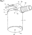
Fig. 1 is a perspective view of a valve device (the first example) according to one embodiment of the present invention. -
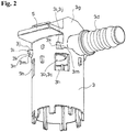
Fig. 2 is a perspective view of an inside case forming the valve device of the first example. -
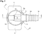
Fig. 3 is a plan view of the valve device of the first example. -
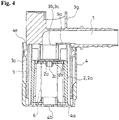
Fig. 4 is a cross-sectional view taken along a line A-A inFig. 3 , and shows an open valve state wherein a float valve is located in a lower position. -
Fig. 5 is a cross-sectional view taken along a line B-B inFig. 3 , and shows the open valve state wherein the float valve is located in the lower position. -
Fig. 6 is a side view of the valve device (a second example) according to another embodiment of the present invention. -
Fig. 7 is a plan view of the valve device of the second example. -
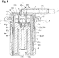
Fig. 8 is a cross-sectional view taken along a line C-C inFig. 7 , and shows the open valve state wherein the float valve is located in the lower position. -
Fig. 9 is an exploded perspective view of the valve device of the second example. -
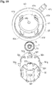
Fig. 10 is a perspective view showing a state wherein a structural member of an attachment portion and the inside case forming the valve device of the second example are separated. - Hereinafter, based on
Fig. 1 to Fig. 10 , typical embodiments of the present invention will be explained. A valve device according to the present embodiment is attached to a fuel tank of an automobile, a two-wheeled vehicle, and the like so as to form a portion of aventilation flow channel 1 of such fuel tank, and functions to communicate inside and outside of the fuel tank in an open valve state. - The valve device (the first example) shown in
Fig. 1 to Fig. 5 is provided in the fuel tank using a bracket (not shown in the drawings) provided inside the fuel tank. - Such valve device comprises a
float valve 2, aninside case 3 housing thefloat valve 2, anoutside case 4 housing theinside case 3, and anattachment portion 5 relative to a tank side. In this example, theattachment portion 5 is integrally provided with theinside case 3.Such float valve 2, insidecase 3, andoutside case 4 are typically made of plastic. - As shown in
Fig. 4 , theinside case 3 includes atop portion 3a and a circular throughhole 3c which becomes a valve opening 3b at a center of thetop portion 3a, and substantially has a cylindrical shape wherein a lower end is open. As shown inFig. 3 , theinside case 3 comprises anexhaust port 3d extending horizontally by integrally connecting a pipe oneend 3e to the center of thetop portion 3a on an upper face side of thetop portion 3a, and having a pipe shape wherein a pipeother end 3f is a connection portion to one end of a pipe member (not shown in the drawings) forming one portion of theventilation flow channel 1. The pipe oneend 3e of theexhaust port 3d communicates with the valve opening 3b, and thereby, theinside case 3 communicates with an outside of a tank through theexhaust port 3d. As shown inFig. 5 , an upper face of thetop portion 3a is surrounded by acircular wall portion 3g. As shown inFig. 3 , a pipe oneend 3e side of theexhaust port 3d is positioned on an inside of thecircular wall portion 3g, and a pipeother end 3f side is positioned on an outside of thecircular wall portion 3g. As shown inFig. 2 , theattachment portion 5 has an ear plate shape projecting horizontally from an outer face of thecircular wall portion 3g. - In a side portion of such inside
case 3, there are provided throughholes 3h. Also,engagement claws 3i relative to theoutside case 4 are provided directly above such throughholes 3h. - In the illustrated example, the
through holes 3h are formed at a portion which is above a position in an approximately middle in an up-and-down direction of the side portion positioned between thetop portion 3a and the lower end of theinside case 3, and is below thetop portion 3a. In the illustrated example, such throughholes 3h are formed in the side portion at four portions at intervals of 90 degrees in a direction of circling a cylinder axis of theinside case 3. Each throughhole 3h respectively has a square window shape wherein an upper side and a lower side are disposed horizontally, and a left side and a right side are arranged vertically. - Also, in the illustrated example, as shown in
Fig. 2 , theengagement claws 3i are respectively formed directly above the four throughholes 3h. In the illustrated example,such engagement claws 3i have a structure of projecting in an eave shape further to a side from a projecting end face of pedestal-shaped projectingportions 3m projecting to the side from an outer face of the side portion of theinside case 3. The pedestal-shaped projectingportions 3m include a horizontal upper face and lower face, vertical left and right side faces, and a vertical projecting end face. The lower face of the pedestal-shaped projecting portion 3m has a level approximately equal to thetop portion 3a. Theengagement claw 3i is formed along a right-and-left direction of the pedestal-shaped projecting portion 3m, and includes anupper face 3j positioned on the same face as the upper face of the pedestal-shaped projecting portion 3m. An interval is formed between alower face 3k of theengagement claw 3i and the lower face of the pedestal-shaped projecting portion 3m, and the projecting end face of the pedestal-shaped projecting portion 3m positioned inside the interval becomes anabutment face 3n relative to an inner face of a side portion of theoutside case 4 in a state wherein theinside case 3 and theoutside case 4 are combined (Fig. 5 ). Thelower face 3k of theengagement claw 3i becomes an inclination face gradually reducing a thickness in an up-and-down direction of theengagement claw 3i toward a tip of theengagement claw 3i. - On the other hand, as shown in
Fig. 1 , theoutside case 4 includes abottom portion 4a, and substantially has a cylindrical shape wherein an upper end is open. A through hole 4b is formed at a center of thebottom portion 4a. On the upper end of theoutside case 4, there are formed projecting pieces 4c projecting upward at four portions at intervals of 90 degrees in a direction of circling a cylinder axis of theoutside case 4. In each projecting piece 4c, there is formed anengagement hole 4d relative to theengagement claw 3i. An upperopen end 4e orthogonal to the cylinder shaft is formed between adjacent projecting pieces 4c. - As shown in
Fig. 4 , an inner diameter of theoutside case 4 is larger than an outer diameter of theinside case 3. Theoutside case 4 and theinside case 3 are combined by inserting theinside case 3 into a position wherein the lower end abuts against the bottom portion of theoutside case 4 with the lower end thereof first from the upperopen end 4e of theoutside case 4 from a state wherein thefloat valve 2 is housed inside theinside case 3. - Specifically, in the illustrated example, immediately before the
inside case 3 is completely inserted into theoutside case 4 as described above, the projecting piece 4c abuts against thelower face 3k which becomes the inclination face of theengagement claw 3i, and the projecting piece 4c is elastically deformed outwardly to allow theinside case 3 to be inserted further. Also, at an entering completion position, eachengagement claw 3i matches thecorresponding engagement hole 4d, and an elastic return of the projecting piece 4c is carried out, so that eachengagement claw 3i engages thecorresponding engagement hole 4d. Thereby, the combined state between theoutside case 4 and theinside case 3 is maintained. - Then, as shown in
Fig. 4 , between the side portion of theoutside case 4 and the side portion of theinside case 3 combined in the aforementioned manner, there is formed aflow channel 1a forming one portion of theventilation flow channel 1 over an entire circumference. - The
float valve 2 comprises a float main member 2a and avalve member 2c attached to an upper portion of the float main member 2a. - In the illustrated example, the float main member 2a substantially closes an upper end, and has a cylinder shape opening a lower end. The
valve member 2c is made of rubber or plastic having a rubber-like elasticity, has a disk shape, and is attached to the float main member 2a by fitting a shortcylindrical portion 2d projecting downwardly from a center of a lower face thereof into a through hole 2b formed at an upper end center of the float main member 2a. Inside the float main member 2a, there is housed acompression coil spring 6 wherein a spring upper end abuts against an upper end inner face of the float main member 2a, and a spring lower end abuts against thebottom portion 4a of theoutside case 4 so as to always apply a certain urging force upwardly relative to thefloat valve 2. - A vertical size of the
float valve 2 is shorter than a distance between thetop portion 3a of theinside case 3 and thebottom portion 4a of theoutside case 4, and an outer diameter of thefloat valve 2 is smaller than an inner diameter of theinside case 3. - As shown in
Fig. 4 andFig. 5 , when thefloat valve 2 is in a lower position wherein a lower end thereof contacts thebottom portion 4a of theoutside case 4, inside and outside of the tank can communicate through the upperopen end 4e of theoutside case 4, theflow channel 1a, the throughhole 3h of theinside case 3, thevalve opening 3b, and theexhaust port 3d. Here, in the present embodiment, the upperopen end 4e of theoutside case 4 is positioned above the throughhole 3h of theinside case 3. Thereby, one portion of theventilation flow channel 1 formed by the upperopen end 4e, theflow channel 1a, the throughhole 3h of theinside case 3, and thevalve opening 3b meanders up and down so as to prevent an outflow of a fuel to the outside of the tank in a state before thefloat valve 2 sits onto thevalve opening 3b as much as possible. - Especially, in the present embodiment, as shown in
Fig. 2 , theengagement claw 3i is formed directly above the throughhole 3h, andsuch engagement claw 3i can function as an eave of the throughhole 3h, so that even if the fuel in a liquid state enters into theflow channel 1a from the upperopen end 4e before thefloat valve 2 sits onto thevalve opening 3b, such fuel can be prevented from entering into the throughhole 3h as much as possible. - When the fuel in the liquid state flows into the
inside case 3 through the through hole 4b of thebottom portion 4a of theoutside case 4, thefloat valve 2 rises up to a position wherein thevalve member 2c provided on an upper portion thereof sits on an inner face of thetop portion 3a of theinside case 3 circling thevalve opening 3b as a valve seat. Thereby, the aforementioned communication of the inside and outside of the tank is blocked. When the fuel flows out of theinside case 3, thefloat valve 2 lowers again, so that the inside and outside of the tank can communicate again through the valve device. - The valve device (a second example) shown in
Fig. 6 to Fig. 10 is attached to an upper portion of a fuel tank T. The valve device comprises astructural member 40 of an attachment portion relative to the tank side having a size of blocking an attachment hole Ta formed on the upper portion of the fuel tank T; and anoutside case 31 and aninside case 32 which can be inserted into the fuel tank T through the attachment hole Ta, and in a state wherein suchoutside case 31 and insidecase 32 are inserted into the fuel tank T, an outer peripheral portion of thestructural member 40 of the attachment portion is fixed on an outer face of the upper portion of the fuel tank T by welding and the like so as to be provided in the fuel tank T (seeFig. 8 ). - Such valve device comprises the
float valve 2; aninside case 32 housing thefloat valve 2; anoutside case 31 housing theinside case 32; and thestructural member 40 of the attachment portion relative to the tank side.Such float valve 2, insidecase 32, outsidecase 31, andstructural member 40 are typically made of plastic. - The
outside case 31 and theinside case 32 are assembled to form theflow channel 1a forming one portion of theventilation flow channel 1 between the both cases. - The
outside case 31 includes abottom portion 31a, and a circular throughhole 31b at a center of thebottom portion 31a, and substantially has a cylindrical shape wherein an upper end is open. As shown inFig. 9 , in an upper end portion of theoutside case 31, there is formed a plurality ofconcave notch portions outside case 31, and the upper end portion of theoutside case 31 has a crown shape. In a projecting-piece-like portion 31d remaining between adjacentconcave notch portions outside case 31, there is formed anengagement hole 31e. - On the other hand, as shown in
Fig. 9 , theinside case 32 includes atop portion 32a and a circular first throughhole 32b at a center of thetop portion 32a, and substantially has a cylindrical shape wherein a lower end is open. In a side portion of theinside case 32, there are formed engagedportions 32c relative toengagement pieces 41d of thestructural member 40, throughholes 32f, andengagement claws 32g relative to theengagement holes 31e of theoutside case 31. - In the illustrated example, four engaged
portions 32c are provided with an interval of 90 degrees in a direction of surrounding a cylinder shaft of theinside case 32. In each engagedportion 32c, a lower end is integrally connected to an outer face of theinside case 32, and the engagedportion 32c respectively comprises a pair ofarm portions arm portions inside case 32; andbridge portions 32e ranging between upper ends of the pair ofarm portions - As shown in
Fig. 10 , in the illustrated example, the throughhole 32f is a square-shaped hole penetrating inside and outside of theinside case 32, and formed between the adjacent engagedportions - In the illustrated example, the
engagement claws 32g project from the outer face of theinside case 32, and are respectively provided directly above the throughholes 32f. - On the other hand, in the illustrated example, as shown in
Fig. 8 , thestructural member 40 comprises a shortcylindrical portion 41 wherein an upper end is closed and a lower end is open; and aflange portion 42 projecting outward from the lower end of the shortcylindrical portion 41. - The short
cylindrical portion 41 includes the upper end, i.e. atop portion 41a, and a circular second through hole 41b at a center of thetop portion 41a. Such second through hole 41b extends horizontally by integrally connecting a pipe one end to a center of the top portion 41b on an upper face side of the top portion 41b of the shortcylindrical portion 41, and a pipe other end communicates to the outside of the tank through anexhaust port 41c having a pipe shape which is a connection portion to one end of a pipe member P forming one portion of theventilation flow channel 1. - As shown in
Fig. 9 , in the lower end of the shortcylindrical portion 41 of thestructural member 40, there are formed theengagement pieces 41d formed byelastic pieces 41e projecting downward by integrally connecting the upper end to the lower end of the shortcylindrical portion 41, and projections 41f formed on a lower end outer side of theelastic pieces 41e. In the illustrated example, fourengagement pieces 41d are provided corresponding to the engagedportions 32c with an interval of 90 degrees in a direction of surrounding a cylinder shaft of the shortcylindrical portion 41 of thestructural member 40. - The
outside case 31 and theinside case 32 are combined such that theinside case 32 is inserted into theoutside case 31 from an upper end side of theoutside case 31 with the lower end of theinside case 32 first up to a position wherein the lower end of theinside case 32 hits thebottom portion 31a of theoutside case 31. In such an insertion process, each projecting-piece-like portion 31d respectively abuts against thecorresponding engagement claw 32g positioned directly above the throughhole 32f positioned between the adjacent engagedportions inside case 32 is completely inserted, the projecting-piece-like portion 31d elastically returns to receive theengagement claw 32g into thewindow hole 31e to be engaged. - As shown in
Fig. 8 , an upperopen end 31f (a level of a base portion of the projecting-piece-like portion 31d) of theoutside case 31 is positioned below an upper end of theinside case 32 and above the throughhole 32f. - Also, the
inside case 32 and thestructural member 40 are combined in such a way as to pinch one portion of thecylindrical seal member 7 fitted in the first throughhole 32b to communicate the inner portion to the second through hole 41b, between thetop portion 32a of theinside case 32 forming theinside case 32 wherein the first throughhole 32b is formed, and thetop portion 41a of thestructural member 40 wherein the second through hole 41b is formed. - The
cylindrical seal member 7 is made of rubber or plastic having the rubber-like elasticity. In the illustrated example, as shown inFig. 9 , suchcylindrical seal member 7 includes anouter flange portion 7a having a circular shape at a cylinder upper end. On an upper face of theouter flange portion 7a, there is formed a circular projecting piece 7b. An outer diameter of theouter flange portion 7a is larger than a hole diameter of the first throughhole 32b. As shown inFig. 8 , in an outer peripheral portion of thecylindrical seal member 7, and in a position of an approximately middle in an up-and-down direction thereof, there is formed a circular risingportion 7c. Between the circular risingportion 7c and theouter flange portion 7a, there is formed an interval having a size corresponding to a thickness of thetop portion 32a of theinside case 32 forming theinside case 32. Between the circular risingportion 7c and the cylinder lower end of thecylindrical seal member 7, there is formed a circular inclined face 7d reducing an outer diameter of thecylindrical seal member 7 as coming closer to the cylinder lower end. - In the illustrated example, the
cylindrical seal member 7 is fitted in the first throughhole 32b from above with a cylinder lower end side thereof first. At a completely fitted position, theouter flange portion 7a of thecylindrical seal member 7 contacts an outer face of thetop portion 32a of theinside case 32, and the circular risingportion 7c contacts an inner face of thetop portion 32a of such insidecase 32. - Thus, from a state wherein the
cylindrical seal member 7 is fitted in the first throughhole 32b, when an upper end side of theinside case 32 is entered into the shortcylindrical portion 41 of thestructural member 40 from below such that theengagement piece 41d of thestructural member 40 enters into the inside of each engagedportion 32c of theinside case 32 respectively, the second through hole 41b is positioned directly above the upper end of thecylindrical seal member 7, and theouter flange portion 7a of thecylindrical seal member 7 is pinched by the outer face of thetop portion 32a of theinside case 32, and a portion which is an inner face of thetop portion 41a of thestructural member 40 and surrounds the second through hole 41b. - In the present embodiment, a pinched state of one portion of such
cylindrical seal member 7, i.e. a combined state of theinside case 32 and thestructural member 40, is maintained by engaging theengagement piece 41d with the engagedportion 32c. When theinside case 32 enters thestructural member 40 as mentioned above, the projection 41f abuts against thebridge portion 32e of the engagedportion 32c, and theelastic piece 41e and thearm portion 32d elastically deform to allow theinside case 32 to enter into thestructural member 40, and when theinside case 32 is completely entered into thestructural member 40, the projection 41f enters below thebridge portion 32e, and theelastic piece 41e and thearm portion 32d elastically return so that the projection 41f is caught on thebridge portion 32e. Thereby, the combined state of theinside case 32 and thestructural member 40 is maintained (seeFig. 8 ). - As shown in
Fig. 8 , thefloat valve 2 comprises a floatmain member 20 and avalve member 21 tiltably provided at an upper portion of the floatmain member 20. - In the illustrated example, the float
main member 20 includes anannular space 20b substantially closing an upper end and internally surrounding acore portion 20a, and has a cylinder shape opening theannular space 20b on a lower end side. In theannular space 20b, there is housed thecompression coil spring 6 wherein a spring upper end abuts against an inner back portion of theannular space 20b, and a spring lower end abuts against thebottom portion 31a of theoutside case 31 to always apply a certain amount of urging forces upward relative to thefloat valve 2. - The
valve member 21 includes following respective portions (1) to (4). - (1) A seal portion 21a closing the first through
hole 3b at a time of a rise of thefloat valve 2. - (2) A catching
portion 21b caught on one portion of the floatmain member 20 and becoming a center of the tilting. - (3) An abutment portion 21c protruding on a back side of the seal portion 21a.
- (4) A support point portion 21d abutting against the lower end of the
cylindrical seal member 7 at a time of the tilting. - The abutment portion 21c has a cylinder shape. Then, in the valve device according to the present embodiment, in a state wherein an abutted
portion 20c having a shaft shape formed in the upper portion of the floatmain member 20 is housed inside the abutment portion 21c, and the seal portion 21a is positioned horizontally, thevalve member 21 is supported on the abuttedportion 20c. Therewith, the abutment portion 21c abuts against the abuttedportion 20c by the tilting to thereby move thevalve member 21 in a horizontal direction. - In such valve device, the lower end of the
cylindrical seal member 7 protruding downward from the inner face of thetop portion 32a of theinside case 32 becomes a valve opening of theinside case 32 functioning as the valve seat 7e of thefloat valve 2. - As shown in
Fig. 8 , when thefloat valve 2 is located in the lower position wherein the lower end thereof contacts a bottom portion of theinside case 32, the inside and outside of the tank can communicate through the upperopen end 31f of theoutside case 31, theflow channel 1a, the throughhole 32f of theinside case 32, thecylindrical seal member 7, the second through hole 41b, and theexhaust port 41c. The upperopen end 31f is positioned above the throughhole 32f of theinside case 32, and the throughhole 32f of theinside case 32 is formed in the side portion of theinside case 32, so that one portion of theventilation flow channel 1 formed by such upperopen end 31f, theflow channel 1a, and the throughhole 32f meanders up and down so as to prevent the outflow of the fuel in the liquid state to the outside of the tank in a state before thefloat valve 2 sits onto the valve seat 7e as much as possible. - Especially, in the present embodiment, the
engagement claw 32g is formed directly above the throughhole 32f, andsuch engagement claw 32g can function as the eave of the throughhole 32f, so that even if the fuel in the liquid state enters into theflow channel 1a from the upperopen end 31f before thefloat valve 2 sits onto the valve opening, such fuel can be prevented from entering into the throughhole 32f as much as possible. - When the fuel in the liquid state flows into the
inside case 32 through the throughhole 31b of thebottom portion 31a of theoutside case 31, thefloat valve 2 rises up to the position wherein thevalve member 21 provided on the upper portion thereof sits on the valve seat 7e as the cylinder lower end of thecylindrical seal member 7 facing inside theinside case 32 as the valve seat 7e. Thereby, the aforementioned communication of the inside and outside of the tank is blocked. When the fuel flows out of theinside case 32, thefloat valve 2 lowers again, so that the inside and outside of the tank can communicate again through the valve device. - In the valve device according to the present embodiment, the
cylindrical seal member 7 can seal between thetop portion 41a of thestructural member 40 and thecylindrical seal member 7, and between thecylindrical seal member 7 and thetop portion 32a of theinside case 32 forming theinside case 32 in an airtight state. In the illustrated example, due to the pinching, in the elastically deformed state, theouter flange portion 7a of thecylindrical seal member 7 is pressed against a hole edge portion of the second through hole 41b of thetop portion 41a of thestructural member 40 and a hole edge portion of the first throughhole 32b of thetop portion 32a of theinside case 32 forming theinside case 32, and the ventilation between the valve device and the outside of the tank is carried out only through the inner portion of thecylindrical seal member 7. Also, in the valve device according to the present embodiment, thecylindrical seal member 7 serves as the valve seat 7e of thefloat valve 2 as well. Thereby, in the valve device according to the present embodiment, parts comprising a seal function can be formed by onecylindrical seal member 7 so as to minimize the number of component parts of this kind of valve device, and further reduce costs. - When the fuel flows into the
inside case 32, the seal portion 21a of thevalve member 21 of thefloat valve 2 rising by the aforementioned flowing blocks the lower end of thecylindrical seal member 7, i.e. the valve seat 7e so as to prevent the fuel from flowing to the outside of the tank. While thefloat valve 2 can move down when the fuel flows out of theinside case 32, since the floatmain member 20 and thevalve member 21 are linked on the catchingportion 21b side, and are not linked on a support point portion 21d side, in thevalve member 21, the support point portion 21d abuts against the lower end of thecylindrical seal member 7 to tilt such that the catchingportion 21b side becomes an inclined bottom as a support point of the aforementioned abutting portion. Therewith, while thevalve member 21 contacts the abutment portion 21c against the abuttedportion 20c by the aforementioned tilting, since a position in the horizontal direction of the abuttedportion 20c does not change, thevalve member 21 moves in the horizontal direction while tilting as mentioned above. Thereby, even in a case wherein the inside of the tank has a high pressure, and in a case wherein thecylindrical seal member 7 and the seal portion 21a are made of a material which can be easily attached, a separation between thecylindrical seal member 7 and the seal portion 21a, i.e. a smooth opening of the valve device can be provided. - Also, in the second example, the engaged
portion 32c is positioned below the upperopen end 31f of theoutside case 31. Thereby, the engagedportion 32c of theinside case 32 engaged with theengagement piece 41d of thestructural member 40 of the attachment portion is covered with theoutside case 31, so that an elastic deformation of the engagedportion 32c in a direction of releasing such an engagement is suppressed, and an engagement state between thestructural member 40 and theinside case 32 can be stably secured. - Also, in the second example, a plurality of through
holes 32f is provided, and the engagedportion 32c is positioned between adjacent throughholes 32f in a peripheral direction (the direction of surrounding the cylinder shaft) of theinside case 32. Thereby, the throughhole 32f can be formed on an upper side of the valve device as much as possible, and can appropriately adapt a high draft in the fuel tank. - Incidentally, obviously, the present invention is not limited to the embodiments explained hereinabove, and includes all embodiments which can obtain the object of the present invention.
-
- 1 a ventilation flow channel
- 1a a flow channel
- 2 a float valve
- 3 an inside case
- 3b a valve opening
- 3h a through hole
- 3i an engagement claw
- 4 an outside case
- 4a a bottom portion
- 5 an attachment portion
- Incidentally, all contents of the specification, claims, drawings, and abstract of Japanese Patent Application No.
2015-060481 filed on March 24, 2015
Claims (6)
- A valve device forming a ventilation flow channel for a fuel tank, comprising:a float valve;an inside case including a valve opening relative to the float valve at an upper portion thereof, and housing the float valve;an outside case receiving the inside case from an upper open end, and having a bottom portion; andan attachment portion relative to a tank side,wherein a flow channel which becomes one portion of the ventilation flow channel is formed between a side portion of the inside case and a side portion of the outside case, andthe side portion of the inside case includes a through hole, and further, an engagement claw relative to the outside case directly above the through hole.
- A valve device according to claim 1, wherein the upper open end of the outside case is positioned at an upper side relative to the through hole of the inside case.
- A valve device according to claim 1 or 2, wherein the outside case includes an engagement hole relative to the engagement claw of the inside case.
- A valve device according to claim 3, wherein the side portion of the inside case includes an engaged portion receiving an engagement piece provided in a structural member of the attachment portion by an elastic deformation, and engaging the engagement piece by an elastic return at a receiving end position.
- A valve device according to claim 4, wherein the engaged portion is positioned on a lower side relative to the upper open end of the outside case.
- A valve device according to claim 4 or 5, wherein the through hole includes plural holes, and the engaged portion is positioned between adjacent through holes in a peripheral direction of the inside case.
Applications Claiming Priority (2)
| Application Number | Priority Date | Filing Date | Title |
|---|---|---|---|
| JP2015060481A JP6370250B2 (en) | 2015-03-24 | 2015-03-24 | Valve device |
| PCT/JP2016/058328 WO2016152677A1 (en) | 2015-03-24 | 2016-03-16 | Valve device |
Publications (3)
| Publication Number | Publication Date |
|---|---|
| EP3276154A1 true EP3276154A1 (en) | 2018-01-31 |
| EP3276154A4 EP3276154A4 (en) | 2019-01-23 |
| EP3276154B1 EP3276154B1 (en) | 2020-02-19 |
Family
ID=56978767
Family Applications (1)
| Application Number | Title | Priority Date | Filing Date |
|---|---|---|---|
| EP16768580.9A Active EP3276154B1 (en) | 2015-03-24 | 2016-03-16 | Valve device |
Country Status (5)
| Country | Link |
|---|---|
| US (1) | US10279679B2 (en) |
| EP (1) | EP3276154B1 (en) |
| JP (1) | JP6370250B2 (en) |
| CN (1) | CN107407236B (en) |
| WO (1) | WO2016152677A1 (en) |
Families Citing this family (7)
| Publication number | Priority date | Publication date | Assignee | Title |
|---|---|---|---|---|
| USD899458S1 (en) * | 2017-02-16 | 2020-10-20 | Eaton Corporation | Fill limit venting valve with high shut-off height |
| US10851747B2 (en) * | 2018-07-24 | 2020-12-01 | Toyoda Gosei Co., Ltd. | Mounting structure of fuel device |
| US10940755B2 (en) * | 2018-11-15 | 2021-03-09 | Stant Usa Corp. | Diesel exhaust fluid tank venting system |
| JP7138610B2 (en) * | 2019-10-10 | 2022-09-16 | 株式会社ニフコ | Fuel tank valve gear |
| CN115697748A (en) * | 2020-06-15 | 2023-02-03 | 百乐仕株式会社 | Valve device |
| US12179575B1 (en) * | 2021-02-02 | 2024-12-31 | Piolax, Inc. | Valve device |
| US11920689B2 (en) * | 2022-01-11 | 2024-03-05 | Samsung Electronics Co., Ltd. | Loose type pneumatic valve and loose type pneumatic valve module including the same |
Family Cites Families (13)
| Publication number | Priority date | Publication date | Assignee | Title |
|---|---|---|---|---|
| JPH07269435A (en) | 1994-03-31 | 1995-10-17 | Aisin Seiki Co Ltd | Fuel control valve |
| US6634341B2 (en) * | 1999-04-28 | 2003-10-21 | Walbro Corporation | Vent and rollover valve and fuel pump module |
| US6742536B2 (en) * | 2001-11-13 | 2004-06-01 | Eaton Corporation | Attachment of fuel vapor vent valve to the inside of a fuel tank |
| US6848463B2 (en) * | 2003-02-05 | 2005-02-01 | Ti Group Automotive Systems, L.L.C. | Vapor vent valve |
| JP3988671B2 (en) * | 2003-03-28 | 2007-10-10 | 豊田合成株式会社 | Valve for fuel tank |
| US7147017B2 (en) * | 2004-06-28 | 2006-12-12 | Alfmeier Corporation | Fill limit vent valve assembly |
| JP4742994B2 (en) * | 2005-09-28 | 2011-08-10 | 豊田合成株式会社 | Fuel shut-off valve |
| JP2008240711A (en) * | 2007-03-29 | 2008-10-09 | Toyoda Gosei Co Ltd | Fuel cutoff valve |
| JP5429112B2 (en) * | 2010-02-02 | 2014-02-26 | 京三電機株式会社 | Full tank control valve device |
| JP2012006456A (en) * | 2010-06-24 | 2012-01-12 | Toyoda Gosei Co Ltd | Fuel cutoff valve |
| JP5801086B2 (en) | 2011-04-04 | 2015-10-28 | 株式会社ニフコ | Fuel tank connector |
| JP5827573B2 (en) * | 2012-01-17 | 2015-12-02 | 株式会社ニフコ | valve |
| KR20150012283A (en) | 2012-05-10 | 2015-02-03 | 이턴 코포레이션 | Quick response float-operated vapor vent valve |
-
2015
- 2015-03-24 JP JP2015060481A patent/JP6370250B2/en active Active
-
2016
- 2016-03-16 US US15/555,850 patent/US10279679B2/en active Active
- 2016-03-16 WO PCT/JP2016/058328 patent/WO2016152677A1/en not_active Ceased
- 2016-03-16 EP EP16768580.9A patent/EP3276154B1/en active Active
- 2016-03-16 CN CN201680013231.3A patent/CN107407236B/en active Active
Also Published As
| Publication number | Publication date |
|---|---|
| JP2016180348A (en) | 2016-10-13 |
| JP6370250B2 (en) | 2018-08-08 |
| US10279679B2 (en) | 2019-05-07 |
| EP3276154A4 (en) | 2019-01-23 |
| CN107407236B (en) | 2019-07-23 |
| US20180043766A1 (en) | 2018-02-15 |
| CN107407236A (en) | 2017-11-28 |
| EP3276154B1 (en) | 2020-02-19 |
| WO2016152677A1 (en) | 2016-09-29 |
Similar Documents
| Publication | Publication Date | Title |
|---|---|---|
| EP3276154B1 (en) | Valve device | |
| EP3141785B1 (en) | Valve device | |
| JP4517350B2 (en) | How to install the fuel vapor discharge valve in the fuel tank | |
| JP4869201B2 (en) | Float valve device | |
| EP3141784B1 (en) | Valve device | |
| JP6203296B2 (en) | Valve device | |
| US20170274760A1 (en) | Valve case mounting structure | |
| US11009147B2 (en) | Valve device for fuel tank | |
| WO2015122407A1 (en) | Valve device | |
| JP2006144756A (en) | Fuel tank pump module structure | |
| JP2007176336A (en) | Fuel shut-off valve | |
| EP1683672A2 (en) | Fuel-effusion prevention valve | |
| WO2021085122A1 (en) | Valve device | |
| JP5876731B2 (en) | Fuel tank connector | |
| JP2008075596A (en) | Fuel cutoff valve | |
| JPH11190258A (en) | Fuel shutoff valve | |
| JP4506459B2 (en) | Fuel shut-off valve | |
| JP2007253778A (en) | Fuel shut-off valve | |
| JP2007276499A (en) | Fuel shutoff valve | |
| JP2008075622A (en) | Fuel cutoff valve |
Legal Events
| Date | Code | Title | Description |
|---|---|---|---|
| STAA | Information on the status of an ep patent application or granted ep patent |
Free format text: STATUS: THE INTERNATIONAL PUBLICATION HAS BEEN MADE |
|
| PUAI | Public reference made under article 153(3) epc to a published international application that has entered the european phase |
Free format text: ORIGINAL CODE: 0009012 |
|
| STAA | Information on the status of an ep patent application or granted ep patent |
Free format text: STATUS: REQUEST FOR EXAMINATION WAS MADE |
|
| 17P | Request for examination filed |
Effective date: 20170914 |
|
| AK | Designated contracting states |
Kind code of ref document: A1 Designated state(s): AL AT BE BG CH CY CZ DE DK EE ES FI FR GB GR HR HU IE IS IT LI LT LU LV MC MK MT NL NO PL PT RO RS SE SI SK SM TR |
|
| AX | Request for extension of the european patent |
Extension state: BA ME |
|
| DAV | Request for validation of the european patent (deleted) | ||
| DAX | Request for extension of the european patent (deleted) | ||
| A4 | Supplementary search report drawn up and despatched |
Effective date: 20190104 |
|
| RIC1 | Information provided on ipc code assigned before grant |
Ipc: B60K 15/035 20060101ALI20181220BHEP Ipc: F02M 37/00 20060101AFI20181220BHEP Ipc: F16K 31/22 20060101ALI20181220BHEP |
|
| GRAP | Despatch of communication of intention to grant a patent |
Free format text: ORIGINAL CODE: EPIDOSNIGR1 |
|
| STAA | Information on the status of an ep patent application or granted ep patent |
Free format text: STATUS: GRANT OF PATENT IS INTENDED |
|
| INTG | Intention to grant announced |
Effective date: 20190919 |
|
| GRAS | Grant fee paid |
Free format text: ORIGINAL CODE: EPIDOSNIGR3 |
|
| GRAA | (expected) grant |
Free format text: ORIGINAL CODE: 0009210 |
|
| STAA | Information on the status of an ep patent application or granted ep patent |
Free format text: STATUS: THE PATENT HAS BEEN GRANTED |
|
| AK | Designated contracting states |
Kind code of ref document: B1 Designated state(s): AL AT BE BG CH CY CZ DE DK EE ES FI FR GB GR HR HU IE IS IT LI LT LU LV MC MK MT NL NO PL PT RO RS SE SI SK SM TR |
|
| REG | Reference to a national code |
Ref country code: CH Ref legal event code: EP |
|
| REG | Reference to a national code |
Ref country code: DE Ref legal event code: R096 Ref document number: 602016030152 Country of ref document: DE |
|
| REG | Reference to a national code |
Ref country code: AT Ref legal event code: REF Ref document number: 1235251 Country of ref document: AT Kind code of ref document: T Effective date: 20200315 |
|
| REG | Reference to a national code |
Ref country code: IE Ref legal event code: FG4D |
|
| REG | Reference to a national code |
Ref country code: NL Ref legal event code: MP Effective date: 20200219 |
|
| PG25 | Lapsed in a contracting state [announced via postgrant information from national office to epo] |
Ref country code: RS Free format text: LAPSE BECAUSE OF FAILURE TO SUBMIT A TRANSLATION OF THE DESCRIPTION OR TO PAY THE FEE WITHIN THE PRESCRIBED TIME-LIMIT Effective date: 20200219 Ref country code: FI Free format text: LAPSE BECAUSE OF FAILURE TO SUBMIT A TRANSLATION OF THE DESCRIPTION OR TO PAY THE FEE WITHIN THE PRESCRIBED TIME-LIMIT Effective date: 20200219 Ref country code: NO Free format text: LAPSE BECAUSE OF FAILURE TO SUBMIT A TRANSLATION OF THE DESCRIPTION OR TO PAY THE FEE WITHIN THE PRESCRIBED TIME-LIMIT Effective date: 20200519 |
|
| REG | Reference to a national code |
Ref country code: LT Ref legal event code: MG4D |
|
| PG25 | Lapsed in a contracting state [announced via postgrant information from national office to epo] |
Ref country code: SE Free format text: LAPSE BECAUSE OF FAILURE TO SUBMIT A TRANSLATION OF THE DESCRIPTION OR TO PAY THE FEE WITHIN THE PRESCRIBED TIME-LIMIT Effective date: 20200219 Ref country code: GR Free format text: LAPSE BECAUSE OF FAILURE TO SUBMIT A TRANSLATION OF THE DESCRIPTION OR TO PAY THE FEE WITHIN THE PRESCRIBED TIME-LIMIT Effective date: 20200520 Ref country code: LV Free format text: LAPSE BECAUSE OF FAILURE TO SUBMIT A TRANSLATION OF THE DESCRIPTION OR TO PAY THE FEE WITHIN THE PRESCRIBED TIME-LIMIT Effective date: 20200219 Ref country code: IS Free format text: LAPSE BECAUSE OF FAILURE TO SUBMIT A TRANSLATION OF THE DESCRIPTION OR TO PAY THE FEE WITHIN THE PRESCRIBED TIME-LIMIT Effective date: 20200619 Ref country code: BG Free format text: LAPSE BECAUSE OF FAILURE TO SUBMIT A TRANSLATION OF THE DESCRIPTION OR TO PAY THE FEE WITHIN THE PRESCRIBED TIME-LIMIT Effective date: 20200519 Ref country code: HR Free format text: LAPSE BECAUSE OF FAILURE TO SUBMIT A TRANSLATION OF THE DESCRIPTION OR TO PAY THE FEE WITHIN THE PRESCRIBED TIME-LIMIT Effective date: 20200219 |
|
| PG25 | Lapsed in a contracting state [announced via postgrant information from national office to epo] |
Ref country code: NL Free format text: LAPSE BECAUSE OF FAILURE TO SUBMIT A TRANSLATION OF THE DESCRIPTION OR TO PAY THE FEE WITHIN THE PRESCRIBED TIME-LIMIT Effective date: 20200219 |
|
| PG25 | Lapsed in a contracting state [announced via postgrant information from national office to epo] |
Ref country code: SM Free format text: LAPSE BECAUSE OF FAILURE TO SUBMIT A TRANSLATION OF THE DESCRIPTION OR TO PAY THE FEE WITHIN THE PRESCRIBED TIME-LIMIT Effective date: 20200219 Ref country code: LT Free format text: LAPSE BECAUSE OF FAILURE TO SUBMIT A TRANSLATION OF THE DESCRIPTION OR TO PAY THE FEE WITHIN THE PRESCRIBED TIME-LIMIT Effective date: 20200219 Ref country code: PT Free format text: LAPSE BECAUSE OF FAILURE TO SUBMIT A TRANSLATION OF THE DESCRIPTION OR TO PAY THE FEE WITHIN THE PRESCRIBED TIME-LIMIT Effective date: 20200712 Ref country code: SK Free format text: LAPSE BECAUSE OF FAILURE TO SUBMIT A TRANSLATION OF THE DESCRIPTION OR TO PAY THE FEE WITHIN THE PRESCRIBED TIME-LIMIT Effective date: 20200219 Ref country code: ES Free format text: LAPSE BECAUSE OF FAILURE TO SUBMIT A TRANSLATION OF THE DESCRIPTION OR TO PAY THE FEE WITHIN THE PRESCRIBED TIME-LIMIT Effective date: 20200219 Ref country code: DK Free format text: LAPSE BECAUSE OF FAILURE TO SUBMIT A TRANSLATION OF THE DESCRIPTION OR TO PAY THE FEE WITHIN THE PRESCRIBED TIME-LIMIT Effective date: 20200219 Ref country code: CZ Free format text: LAPSE BECAUSE OF FAILURE TO SUBMIT A TRANSLATION OF THE DESCRIPTION OR TO PAY THE FEE WITHIN THE PRESCRIBED TIME-LIMIT Effective date: 20200219 Ref country code: RO Free format text: LAPSE BECAUSE OF FAILURE TO SUBMIT A TRANSLATION OF THE DESCRIPTION OR TO PAY THE FEE WITHIN THE PRESCRIBED TIME-LIMIT Effective date: 20200219 Ref country code: EE Free format text: LAPSE BECAUSE OF FAILURE TO SUBMIT A TRANSLATION OF THE DESCRIPTION OR TO PAY THE FEE WITHIN THE PRESCRIBED TIME-LIMIT Effective date: 20200219 |
|
| REG | Reference to a national code |
Ref country code: CH Ref legal event code: PL |
|
| REG | Reference to a national code |
Ref country code: AT Ref legal event code: MK05 Ref document number: 1235251 Country of ref document: AT Kind code of ref document: T Effective date: 20200219 |
|
| REG | Reference to a national code |
Ref country code: DE Ref legal event code: R097 Ref document number: 602016030152 Country of ref document: DE |
|
| PG25 | Lapsed in a contracting state [announced via postgrant information from national office to epo] |
Ref country code: MC Free format text: LAPSE BECAUSE OF FAILURE TO SUBMIT A TRANSLATION OF THE DESCRIPTION OR TO PAY THE FEE WITHIN THE PRESCRIBED TIME-LIMIT Effective date: 20200219 |
|
| REG | Reference to a national code |
Ref country code: BE Ref legal event code: MM Effective date: 20200331 |
|
| PLBE | No opposition filed within time limit |
Free format text: ORIGINAL CODE: 0009261 |
|
| STAA | Information on the status of an ep patent application or granted ep patent |
Free format text: STATUS: NO OPPOSITION FILED WITHIN TIME LIMIT |
|
| PG25 | Lapsed in a contracting state [announced via postgrant information from national office to epo] |
Ref country code: LU Free format text: LAPSE BECAUSE OF NON-PAYMENT OF DUE FEES Effective date: 20200316 |
|
| 26N | No opposition filed |
Effective date: 20201120 |
|
| PG25 | Lapsed in a contracting state [announced via postgrant information from national office to epo] |
Ref country code: CH Free format text: LAPSE BECAUSE OF NON-PAYMENT OF DUE FEES Effective date: 20200331 Ref country code: IE Free format text: LAPSE BECAUSE OF NON-PAYMENT OF DUE FEES Effective date: 20200316 Ref country code: IT Free format text: LAPSE BECAUSE OF FAILURE TO SUBMIT A TRANSLATION OF THE DESCRIPTION OR TO PAY THE FEE WITHIN THE PRESCRIBED TIME-LIMIT Effective date: 20200219 Ref country code: AT Free format text: LAPSE BECAUSE OF FAILURE TO SUBMIT A TRANSLATION OF THE DESCRIPTION OR TO PAY THE FEE WITHIN THE PRESCRIBED TIME-LIMIT Effective date: 20200219 Ref country code: LI Free format text: LAPSE BECAUSE OF NON-PAYMENT OF DUE FEES Effective date: 20200331 |
|
| PG25 | Lapsed in a contracting state [announced via postgrant information from national office to epo] |
Ref country code: BE Free format text: LAPSE BECAUSE OF NON-PAYMENT OF DUE FEES Effective date: 20200331 Ref country code: SI Free format text: LAPSE BECAUSE OF FAILURE TO SUBMIT A TRANSLATION OF THE DESCRIPTION OR TO PAY THE FEE WITHIN THE PRESCRIBED TIME-LIMIT Effective date: 20200219 Ref country code: PL Free format text: LAPSE BECAUSE OF FAILURE TO SUBMIT A TRANSLATION OF THE DESCRIPTION OR TO PAY THE FEE WITHIN THE PRESCRIBED TIME-LIMIT Effective date: 20200219 |
|
| PGFP | Annual fee paid to national office [announced via postgrant information from national office to epo] |
Ref country code: GB Payment date: 20220127 Year of fee payment: 7 |
|
| PG25 | Lapsed in a contracting state [announced via postgrant information from national office to epo] |
Ref country code: TR Free format text: LAPSE BECAUSE OF FAILURE TO SUBMIT A TRANSLATION OF THE DESCRIPTION OR TO PAY THE FEE WITHIN THE PRESCRIBED TIME-LIMIT Effective date: 20200219 Ref country code: MT Free format text: LAPSE BECAUSE OF FAILURE TO SUBMIT A TRANSLATION OF THE DESCRIPTION OR TO PAY THE FEE WITHIN THE PRESCRIBED TIME-LIMIT Effective date: 20200219 Ref country code: CY Free format text: LAPSE BECAUSE OF FAILURE TO SUBMIT A TRANSLATION OF THE DESCRIPTION OR TO PAY THE FEE WITHIN THE PRESCRIBED TIME-LIMIT Effective date: 20200219 |
|
| PG25 | Lapsed in a contracting state [announced via postgrant information from national office to epo] |
Ref country code: MK Free format text: LAPSE BECAUSE OF FAILURE TO SUBMIT A TRANSLATION OF THE DESCRIPTION OR TO PAY THE FEE WITHIN THE PRESCRIBED TIME-LIMIT Effective date: 20200219 Ref country code: AL Free format text: LAPSE BECAUSE OF FAILURE TO SUBMIT A TRANSLATION OF THE DESCRIPTION OR TO PAY THE FEE WITHIN THE PRESCRIBED TIME-LIMIT Effective date: 20200219 |
|
| GBPC | Gb: european patent ceased through non-payment of renewal fee |
Effective date: 20230316 |
|
| PG25 | Lapsed in a contracting state [announced via postgrant information from national office to epo] |
Ref country code: GB Free format text: LAPSE BECAUSE OF NON-PAYMENT OF DUE FEES Effective date: 20230316 |
|
| PG25 | Lapsed in a contracting state [announced via postgrant information from national office to epo] |
Ref country code: GB Free format text: LAPSE BECAUSE OF NON-PAYMENT OF DUE FEES Effective date: 20230316 |
|
| PGFP | Annual fee paid to national office [announced via postgrant information from national office to epo] |
Ref country code: DE Payment date: 20250128 Year of fee payment: 10 |
|
| PGFP | Annual fee paid to national office [announced via postgrant information from national office to epo] |
Ref country code: FR Payment date: 20250210 Year of fee payment: 10 |