EP3276117B1 - Double-canvas door - Google Patents
Double-canvas door Download PDFInfo
- Publication number
- EP3276117B1 EP3276117B1 EP16771440.1A EP16771440A EP3276117B1 EP 3276117 B1 EP3276117 B1 EP 3276117B1 EP 16771440 A EP16771440 A EP 16771440A EP 3276117 B1 EP3276117 B1 EP 3276117B1
- Authority
- EP
- European Patent Office
- Prior art keywords
- canvases
- door
- band
- winding roller
- roller
- Prior art date
- Legal status (The legal status is an assumption and is not a legal conclusion. Google has not performed a legal analysis and makes no representation as to the accuracy of the status listed.)
- Active
Links
- 208000018747 cerebellar ataxia with neuropathy and bilateral vestibular areflexia syndrome Diseases 0.000 claims description 40
- 238000004804 winding Methods 0.000 claims description 27
- 238000010276 construction Methods 0.000 description 4
- 238000010438 heat treatment Methods 0.000 description 2
- 238000009413 insulation Methods 0.000 description 2
- 239000011324 bead Substances 0.000 description 1
- 230000005540 biological transmission Effects 0.000 description 1
- 238000007664 blowing Methods 0.000 description 1
- 230000000295 complement effect Effects 0.000 description 1
- 230000008878 coupling Effects 0.000 description 1
- 238000010168 coupling process Methods 0.000 description 1
- 238000005859 coupling reaction Methods 0.000 description 1
- 238000010348 incorporation Methods 0.000 description 1
- 238000004519 manufacturing process Methods 0.000 description 1
- 239000000463 material Substances 0.000 description 1
Images


Classifications
-
- E—FIXED CONSTRUCTIONS
- E06—DOORS, WINDOWS, SHUTTERS, OR ROLLER BLINDS IN GENERAL; LADDERS
- E06B—FIXED OR MOVABLE CLOSURES FOR OPENINGS IN BUILDINGS, VEHICLES, FENCES OR LIKE ENCLOSURES IN GENERAL, e.g. DOORS, WINDOWS, BLINDS, GATES
- E06B9/00—Screening or protective devices for wall or similar openings, with or without operating or securing mechanisms; Closures of similar construction
- E06B9/02—Shutters, movable grilles, or other safety closing devices, e.g. against burglary
- E06B9/08—Roll-type closures
- E06B9/11—Roller shutters
- E06B9/13—Roller shutters with closing members of one piece, e.g. of corrugated sheet metal
-
- E—FIXED CONSTRUCTIONS
- E06—DOORS, WINDOWS, SHUTTERS, OR ROLLER BLINDS IN GENERAL; LADDERS
- E06B—FIXED OR MOVABLE CLOSURES FOR OPENINGS IN BUILDINGS, VEHICLES, FENCES OR LIKE ENCLOSURES IN GENERAL, e.g. DOORS, WINDOWS, BLINDS, GATES
- E06B9/00—Screening or protective devices for wall or similar openings, with or without operating or securing mechanisms; Closures of similar construction
- E06B9/02—Shutters, movable grilles, or other safety closing devices, e.g. against burglary
- E06B9/08—Roll-type closures
- E06B9/11—Roller shutters
- E06B9/17—Parts or details of roller shutters, e.g. suspension devices, shutter boxes, wicket doors, ventilation openings
- E06B9/171—Rollers therefor; Fastening roller shutters to rollers
-
- E—FIXED CONSTRUCTIONS
- E06—DOORS, WINDOWS, SHUTTERS, OR ROLLER BLINDS IN GENERAL; LADDERS
- E06B—FIXED OR MOVABLE CLOSURES FOR OPENINGS IN BUILDINGS, VEHICLES, FENCES OR LIKE ENCLOSURES IN GENERAL, e.g. DOORS, WINDOWS, BLINDS, GATES
- E06B9/00—Screening or protective devices for wall or similar openings, with or without operating or securing mechanisms; Closures of similar construction
- E06B9/24—Screens or other constructions affording protection against light, especially against sunshine; Similar screens for privacy or appearance; Slat blinds
- E06B9/40—Roller blinds
- E06B9/42—Parts or details of roller blinds, e.g. suspension devices, blind boxes
- E06B9/44—Rollers therefor; Fastening roller blinds to rollers
-
- E—FIXED CONSTRUCTIONS
- E06—DOORS, WINDOWS, SHUTTERS, OR ROLLER BLINDS IN GENERAL; LADDERS
- E06B—FIXED OR MOVABLE CLOSURES FOR OPENINGS IN BUILDINGS, VEHICLES, FENCES OR LIKE ENCLOSURES IN GENERAL, e.g. DOORS, WINDOWS, BLINDS, GATES
- E06B9/00—Screening or protective devices for wall or similar openings, with or without operating or securing mechanisms; Closures of similar construction
- E06B9/24—Screens or other constructions affording protection against light, especially against sunshine; Similar screens for privacy or appearance; Slat blinds
- E06B2009/2423—Combinations of at least two screens
- E06B2009/2447—Parallel screens
- E06B2009/2458—Parallel screens moving simultaneously
Definitions
- the object of the present invention is a double-canvas door, which presents a series of specific construction characteristics that are aimed at simplifying its movement and increasing the watertightness of the chamber formed by the two canvases when the door is in the closed position.
- This invention is applicable in the field dedicated to the manufacture of doors, and specifically insulating doors.
- Doors equipped with two closing canvases mounted on vertical guides and with each upper end secured to a motorized roller, which, when they rotate in one direction or the other cause the respective canvases to roll and unroll, and consequently open and close the door, are known.
- the two canvases create an intermediate chamber.
- the intermediate chamber provides thermal insulation between the two zones separated by the door; the incorporation of a heating set into this type of door to supply temperature-controlled air to the intermediate chamber is also known.
- a door of this type is described, for example, in utility model ES1110857 U .
- Document US 2014/0360679 A1 discloses a roll-up curtain closure system having at two flexible curtains, each having a first end fixedly attached adjacent a portal along a first end thereof and a second end folded back on itself to define a pocket opening towards the portal first end.
- the second ends of the two curtains are connected to one another and to a band coupled to a motor-driven winding roller.
- An elongated tension rod is captured within the pocket of each curtain, and a single motor is operably connected to the winding roller for varying the height of the pockets.
- Document US 4275645 A discloses a double-canvas door comprising a frame provided with two pairs of vertical rails for moving two canvases between door open and closed positions.
- the two canvases define an intermediate chamber therebetween, and the upper ends of the canvases are connected to one another and to a band coupled to a motor-driven winding roller.
- a connection between the upper ends of the canvases closes the upper end of the intermediate chamber when the door is closed.
- the lower ends of the two canvases are connected to respective spaced parallel spring-loaded rollers positioned below the opening, so that the canvases are individually rolled up on the respective spring-loaded rollers in the open position and only the band is rolled up on the motor-driven roller in the closed position.
- Document US 2013098567 A1 discloses an insulated flexible curtain comprising a flexible insulated pad within an internal space of a pliable hollow panel.
- the curtain is sufficiently pliable to be selectively rolled up on a winding roller and unrolled so that the curtain substantially recovers to its original shape. Lateral edges of the curtain are guided in a pair of wall-mounted tracks.
- the double-canvas door of the invention according to claim 1 presents a series of construction characteristics that enable it to resolve the aforementioned problem, greatly simplifying the simultaneous movement of the two canvases of the door and closing the top of the intermediate chamber, which significantly improves the insulation of the door in the closed position.
- a double-canvas door has been developed that comprises a single roller for the simultaneous winding of both canvases and a single drive motor, which greatly simplifies door construction and cost.
- the upper ends of the canvases are connected to one another and to a band coupled to the winding roller, with this connection closing the upper end of the intermediate chamber that helps keep the temperature and atmospheric conditions inside the door stable when the door is closed.
- the door comprises a connection profile with several parallel slots for securing the ends of the two canvases and a first end of the band coupled to the winding roller.
- the winding roller comprises a first longitudinal slot to secure the band, and a second longitudinal slot that holds the connection profile, so that when the canvases are in the wound position, the connection between the canvases and the band does not extend beyond the general profile of the winding roller and so that the coupling between the connection profile and the second opening work together to support the tension of the canvases.
- this double-canvas door comprises a frame (1) provided on each side with a pair of guides (2a, 2b) for moving the canvases (3a, 3b) fitted at the lower ends with tension weights (31) and connected to one another at the upper end by a connection profile (4) to a band (5) coupled to a single winding roller (6) actuated by a drive set (61) such that when the winding roller rotates in one direction or the other, the two canvases (3a, 3b) simultaneously wind or unwind on the roller (6) and consequently open or close the door.
- the upper part of the door is equipped with a cover (7).
- the canvases (3a, 3b) create an intermediate chamber (8) therebetween, which is equipped on the sides with a series of blower nozzles (9) connected by a series of conduits (91) to a heating set (10) responsible for blowing temperature-controlled air into said intermediate space.
- the door comprises a centring profile (11) for the canvases (3a, 3b) between the upper end of the guides (2a, 2b).
- connection profile (3) in this case with a triangular-shaped general cross-section has several parallel slots (41) to secure the upper end of the two canvases (3a, 3b) and a first end of the band coupled to the winding roller (5).
- the canvases (3a, 3b) and the band coupled to the winding roller (5) are secured to the connection profile in a known manner by inserting a series of thicknesses in the canvases (3a, 3b) into the slots (41) and into the band coupled to the winding roller (5) created with the respective round beads.
- the winding roller comprises a first longitudinal slot (62) to secure a second end of the band coupled to the winding roller (5), and a second longitudinal slot (63) that holds the connection profile (4) when the canvases (3a, 3b) are wound on the roller (6) as shown in figure 4 .
- connection profile (4) and the connection zones between it and the canvases (3a, 3b) and the band coupled to the winding roller (5) are recessed with respect to the general cylindrical surface area of the winding roller, avoiding any bumps that could cause marks or deformation of the canvases (3a, 3b).
- connection of the upper end of the canvases (3a, 3b) to the connection profile (4) closes the top of the intermediate chamber (8), which helps maintain the existing temperature conditions in the atmosphere of said intermediate chamber (8).
Description
- The object of the present invention is a double-canvas door, which presents a series of specific construction characteristics that are aimed at simplifying its movement and increasing the watertightness of the chamber formed by the two canvases when the door is in the closed position.
- This invention is applicable in the field dedicated to the manufacture of doors, and specifically insulating doors.
- Doors equipped with two closing canvases mounted on vertical guides and with each upper end secured to a motorized roller, which, when they rotate in one direction or the other cause the respective canvases to roll and unroll, and consequently open and close the door, are known.
- When the door is in the closed position, the two canvases create an intermediate chamber.
- The intermediate chamber provides thermal insulation between the two zones separated by the door; the incorporation of a heating set into this type of door to supply temperature-controlled air to the intermediate chamber is also known.
- A door of this type is described, for example, in utility model
ES1110857 U - One of the general drawbacks with this type of door is the complexity of the construction and the cost as a result of the use of two winding rollers and the means required to motorize them. These means of motorization may consist of two motors, one for each roller, or a single motor and a transmission to simultaneously actuate both rollers, as in the case of the aforementioned
prior art ES 1 110 857 U - The use of two winding rollers poses a problem of watertightness of the intermediate chamber when the door is closed. Although the winding rollers are housed in an upper cover or housing, the closure of the aforementioned intermediate chamber at the upper end is practically infeasible and causes significant leaks of the temperature-controlled air blown into the chamber.
- The applicant of the present invention is not aware of the existence of any prior art that satisfactorily resolves the aforementioned issues.
- Document
US 2014/0360679 A1 discloses a roll-up curtain closure system having at two flexible curtains, each having a first end fixedly attached adjacent a portal along a first end thereof and a second end folded back on itself to define a pocket opening towards the portal first end. The second ends of the two curtains are connected to one another and to a band coupled to a motor-driven winding roller. An elongated tension rod is captured within the pocket of each curtain, and a single motor is operably connected to the winding roller for varying the height of the pockets. - Document
US 4275645 A discloses a double-canvas door comprising a frame provided with two pairs of vertical rails for moving two canvases between door open and closed positions. The two canvases define an intermediate chamber therebetween, and the upper ends of the canvases are connected to one another and to a band coupled to a motor-driven winding roller. A connection between the upper ends of the canvases closes the upper end of the intermediate chamber when the door is closed. The lower ends of the two canvases are connected to respective spaced parallel spring-loaded rollers positioned below the opening, so that the canvases are individually rolled up on the respective spring-loaded rollers in the open position and only the band is rolled up on the motor-driven roller in the closed position. - Document
US 2013098567 A1 discloses an insulated flexible curtain comprising a flexible insulated pad within an internal space of a pliable hollow panel. The curtain is sufficiently pliable to be selectively rolled up on a winding roller and unrolled so that the curtain substantially recovers to its original shape. Lateral edges of the curtain are guided in a pair of wall-mounted tracks. - The double-canvas door of the invention according to
claim 1 presents a series of construction characteristics that enable it to resolve the aforementioned problem, greatly simplifying the simultaneous movement of the two canvases of the door and closing the top of the intermediate chamber, which significantly improves the insulation of the door in the closed position. - To achieve the proposed objectives, a double-canvas door has been developed that comprises a single roller for the simultaneous winding of both canvases and a single drive motor, which greatly simplifies door construction and cost.
- The upper ends of the canvases are connected to one another and to a band coupled to the winding roller, with this connection closing the upper end of the intermediate chamber that helps keep the temperature and atmospheric conditions inside the door stable when the door is closed.
- In one embodiment of the invention, to create this connection, the door comprises a connection profile with several parallel slots for securing the ends of the two canvases and a first end of the band coupled to the winding roller.
- The winding roller comprises a first longitudinal slot to secure the band, and a second longitudinal slot that holds the connection profile, so that when the canvases are in the wound position, the connection between the canvases and the band does not extend beyond the general profile of the winding roller and so that the coupling between the connection profile and the second opening work together to support the tension of the canvases.
- To complement the description that is being provided and in order to provide a better understanding of the characteristics of the invention, a set of drawings is included along with this descriptive summary, in which the following elements have been represented for the purposes of illustration but not limitation:
-
Figure 1 shows a front elevation of an exemplary embodiment of the double-canvas door according to the invention, in the closed position. -
Figure 2 shows a profile view of the double-canvas door in the previous figure cut by a vertical plane, and a detailed close-up view of an upper portion of the door. -
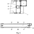
Figure 3 shows a plan view from above of the double-canvas door infigure 1 cut by a horizontal plane. -
Figure 4 shows a close up profile view of an upper portion of the door, which shows the canvases in the open position, and a detailed close-up view of the roller, which shows the connection profile of the canvases and the band, fit into the second longitudinal slot of the shaft. - As observed in
figures 1 to 3 , this double-canvas door comprises a frame (1) provided on each side with a pair of guides (2a, 2b) for moving the canvases (3a, 3b) fitted at the lower ends with tension weights (31) and connected to one another at the upper end by a connection profile (4) to a band (5) coupled to a single winding roller (6) actuated by a drive set (61) such that when the winding roller rotates in one direction or the other, the two canvases (3a, 3b) simultaneously wind or unwind on the roller (6) and consequently open or close the door. The upper part of the door is equipped with a cover (7). - As shown in
figures 2 and3 , the canvases (3a, 3b) create an intermediate chamber (8) therebetween, which is equipped on the sides with a series of blower nozzles (9) connected by a series of conduits (91) to a heating set (10) responsible for blowing temperature-controlled air into said intermediate space. - As shown in the detailed close-up in
figure 2 andfigure 4 , the door comprises a centring profile (11) for the canvases (3a, 3b) between the upper end of the guides (2a, 2b). - As shown in the detailed views of
figures 2 and4 , the connection profile (3), in this case with a triangular-shaped general cross-section has several parallel slots (41) to secure the upper end of the two canvases (3a, 3b) and a first end of the band coupled to the winding roller (5). - In this exemplary embodiment, the canvases (3a, 3b) and the band coupled to the winding roller (5) are secured to the connection profile in a known manner by inserting a series of thicknesses in the canvases (3a, 3b) into the slots (41) and into the band coupled to the winding roller (5) created with the respective round beads.
- The winding roller comprises a first longitudinal slot (62) to secure a second end of the band coupled to the winding roller (5), and a second longitudinal slot (63) that holds the connection profile (4) when the canvases (3a, 3b) are wound on the roller (6) as shown in
figure 4 . - In this wound position, the connection profile (4) and the connection zones between it and the canvases (3a, 3b) and the band coupled to the winding roller (5) are recessed with respect to the general cylindrical surface area of the winding roller, avoiding any bumps that could cause marks or deformation of the canvases (3a, 3b).
- As shown in the detailed view of
figure 2 , the connection of the upper end of the canvases (3a, 3b) to the connection profile (4) closes the top of the intermediate chamber (8), which helps maintain the existing temperature conditions in the atmosphere of said intermediate chamber (8). - Having sufficiently described the nature of the invention, as well as a preferred embodiment, it is hereby stated for the pertinent purposes that the materials, shape, size, and arrangement of the described elements may be modified, provided that this does not alter the essential characteristics of the invention that is claimed below.
Claims (4)
- A double-canvas door comprising a frame (1) provided with guides (2a, 2b) for moving two canvases (3a, 3b) between door open and closed positions, with said canvases defining an intermediate chamber (8) therebetween, the upper ends of the canvases (3a, 3b) being connected to one another and to a means coupled to a winding roller; a single motor (61) being provided for actuating the motor-driven winding roller (6); and a connection between the upper ends of the canvases (3a, 3b) closing an upper end of the intermediate chamber (8) when the door is closed; characterised in that:
said means coupled to said winding roller (6) is a band (5); a pair of said guides (2a, 2b) is provided on each side of the frame (1) for moving the two canvases (3a, 3b); and said winding roller is said single motor-driven roller (6) for the simultaneous winding of both canvases (3a, 3b). - The door according to claim 1, characterised in that the upper ends of the two canvases (3a, 3b) are connected to one another and to the band (5) by a connection profile (4) that has several parallel slots (41) to secure the upper end of the two canvases (3a, 3b) and a first end of the band (5).
- The door according to claim 2, characterised in that the winding motor-driven roller (6) comprises a first longitudinal slot (62) to secure a second end of the band (5), and a second longitudinal slot (63) that holds the connection profile (4) when the band (5) and the canvases (3a, 3b) are wound on the motor-driven roller (6).
- The door according to claim 2 or 3: characterised in that a centring profile (11) for the canvases (3a, 3b) is provided between the upper ends of the guides (2a, 2b).
Applications Claiming Priority (2)
| Application Number | Priority Date | Filing Date | Title |
|---|---|---|---|
| ES201530413A ES2584536B1 (en) | 2015-03-27 | 2015-03-27 | Double canvas door |
| PCT/ES2016/070067 WO2016156635A1 (en) | 2015-03-27 | 2016-02-05 | Double-canvas door |
Publications (3)
| Publication Number | Publication Date |
|---|---|
| EP3276117A1 EP3276117A1 (en) | 2018-01-31 |
| EP3276117A4 EP3276117A4 (en) | 2018-11-21 |
| EP3276117B1 true EP3276117B1 (en) | 2019-10-30 |
Family
ID=56973715
Family Applications (1)
| Application Number | Title | Priority Date | Filing Date |
|---|---|---|---|
| EP16771440.1A Active EP3276117B1 (en) | 2015-03-27 | 2016-02-05 | Double-canvas door |
Country Status (9)
| Country | Link |
|---|---|
| US (1) | US10760333B2 (en) |
| EP (1) | EP3276117B1 (en) |
| JP (1) | JP6430660B2 (en) |
| CA (1) | CA2980661C (en) |
| CL (1) | CL2017002372A1 (en) |
| ES (2) | ES2584536B1 (en) |
| MX (1) | MX2017012265A (en) |
| PT (1) | PT3276117T (en) |
| WO (1) | WO2016156635A1 (en) |
Families Citing this family (2)
| Publication number | Priority date | Publication date | Assignee | Title |
|---|---|---|---|---|
| ES2729731B2 (en) * | 2018-05-04 | 2021-02-17 | Amiserru Sl | ENCLOSURE FOR REFRIGERATED ROOMS |
| CA3090682A1 (en) | 2019-08-21 | 2021-02-21 | Jamison Door Company | Defrosting roll-up climate controlled door |
Family Cites Families (24)
| Publication number | Priority date | Publication date | Assignee | Title |
|---|---|---|---|---|
| US2328257A (en) * | 1941-12-31 | 1943-08-31 | T B Zumstein | Ventilating black-out roller shade |
| US4187896A (en) * | 1977-09-15 | 1980-02-12 | Shore Ronald H | Self-inflating solar curtain |
| US4275645A (en) * | 1978-07-10 | 1981-06-30 | Expertise Assistance Inc. | Closure for service opening |
| SE416418B (en) * | 1979-03-26 | 1980-12-22 | Andrzej Tomasz Iwanicki | INSULATIVE RIDE, INCLUDING AN INFLATABLE ELEMENT |
| US4453584A (en) * | 1981-05-22 | 1984-06-12 | Steele Richard S | Sealing system for movable insulation |
| CA1178013A (en) * | 1981-05-22 | 1984-11-20 | Richard S. Steele | Sealing system for movable insulation |
| JPS58110175U (en) * | 1982-01-22 | 1983-07-27 | 三和シヤツタ−工業株式会社 | Door section structure for adjustable doors |
| DE3202017A1 (en) * | 1982-01-22 | 1983-07-28 | Gebrüder Kömmerling Kunststoffwerke GmbH, 6780 Pirmasens | SHUTTER |
| SE453212B (en) * | 1986-04-17 | 1988-01-18 | Nomafa Ab | DEVICE FOR ROLLING PORTS WITH ATMINSTONE A CHEAP DOOR BLADE |
| WO1991012404A1 (en) * | 1990-02-14 | 1991-08-22 | Frommelt Industries, Inc. | Thermal door system |
| US5566736A (en) * | 1995-11-13 | 1996-10-22 | Crider; Grant W. | Sealable curtain |
| FR2861121A1 (en) * | 2003-10-17 | 2005-04-22 | Nergeco Sa | Snap door for closing structural openings of building, includes curtain with two screens that delimit air cushion, and two transversal tightening bars connected on screens of curtain |
| US7281561B2 (en) * | 2004-06-07 | 2007-10-16 | Donald Anderson | Multi-layered film window system |
| US7614439B2 (en) * | 2004-10-05 | 2009-11-10 | Stephen Lukos | Roller tube having external slot for mounting sheet material |
| CA2549261A1 (en) * | 2006-06-01 | 2007-12-01 | Metaux Satellite Inc. | Lift cord anchor clip for roman shade |
| JP5058606B2 (en) * | 2007-01-10 | 2012-10-24 | 文化シヤッター株式会社 | Compound shutter |
| DE102011010967A1 (en) * | 2011-02-10 | 2012-08-16 | Albert Weiss | Splitting-free roller blind device |
| AU2012300285B2 (en) * | 2011-08-26 | 2017-11-23 | Hunter Douglas Inc. | Cordless retractable roller shade for window coverings |
| US8839842B2 (en) * | 2011-10-21 | 2014-09-23 | Rite-Hite Holding Corporation | Insulated washdown flexible walls and curtains |
| GB201217809D0 (en) * | 2012-10-05 | 2012-11-14 | Fourds Ltd | Roller blind assembly |
| WO2014143057A1 (en) * | 2013-03-15 | 2014-09-18 | Hunter Douglas Inc. | Position lock for roller supported architectural coverings |
| US8919415B1 (en) * | 2013-06-05 | 2014-12-30 | Grant W. Crider | Curtain closure system having impact resistant tension bar |
| ES1110857Y (en) * | 2014-03-03 | 2014-12-04 | Control Y Accesos S L | DOOR ROLLABLE |
| DE202014105368U1 (en) * | 2014-11-10 | 2014-12-01 | Lock Antriebstechnik Gmbh | Winding device for covering building openings |
-
2015
- 2015-03-27 ES ES201530413A patent/ES2584536B1/en active Active
-
2016
- 2016-02-05 EP EP16771440.1A patent/EP3276117B1/en active Active
- 2016-02-05 JP JP2017550488A patent/JP6430660B2/en active Active
- 2016-02-05 WO PCT/ES2016/070067 patent/WO2016156635A1/en active Application Filing
- 2016-02-05 ES ES16771440T patent/ES2757550T3/en active Active
- 2016-02-05 US US15/560,522 patent/US10760333B2/en active Active
- 2016-02-05 PT PT167714401T patent/PT3276117T/en unknown
- 2016-02-05 MX MX2017012265A patent/MX2017012265A/en active IP Right Grant
- 2016-02-05 CA CA2980661A patent/CA2980661C/en active Active
-
2017
- 2017-09-21 CL CL2017002372A patent/CL2017002372A1/en unknown
Non-Patent Citations (1)
| Title |
|---|
| None * |
Also Published As
| Publication number | Publication date |
|---|---|
| PT3276117T (en) | 2019-12-05 |
| US10760333B2 (en) | 2020-09-01 |
| ES2584536B1 (en) | 2017-05-04 |
| ES2584536A1 (en) | 2016-09-28 |
| CA2980661C (en) | 2019-10-29 |
| MX2017012265A (en) | 2018-01-09 |
| EP3276117A4 (en) | 2018-11-21 |
| EP3276117A1 (en) | 2018-01-31 |
| US20180112458A1 (en) | 2018-04-26 |
| WO2016156635A1 (en) | 2016-10-06 |
| CL2017002372A1 (en) | 2018-05-18 |
| JP2018509546A (en) | 2018-04-05 |
| JP6430660B2 (en) | 2018-11-28 |
| CA2980661A1 (en) | 2016-10-06 |
| ES2757550T3 (en) | 2020-04-29 |
Similar Documents
| Publication | Publication Date | Title |
|---|---|---|
| US10815689B2 (en) | Canopy | |
| US20120043029A1 (en) | Dual Panel Window Shade Apparatus with Improved Bottom Weight Bar and Rail | |
| NL1040857B1 (en) | Covering for an architectural opening having coved slats. | |
| US9004574B1 (en) | E Z roller | |
| US6651720B1 (en) | Dual panel window shade apparatus | |
| CA2914478C (en) | Curtain closure system having impact resistant tension bar | |
| ES2522343T3 (en) | Liftgate arrangement as well as shutter device for the door lintel for the same | |
| EP3276117B1 (en) | Double-canvas door | |
| US20180258692A1 (en) | Window Shade Device | |
| US9803421B2 (en) | Door, in particular vertical-lift door, for closing an opening in a wall which separates two different temperature zones from one another | |
| US20120318465A1 (en) | Insulating shade for covering an architectural opening | |
| ES2823228T3 (en) | Enclosure for cold rooms | |
| US8820384B2 (en) | Roller shutter for an opening in a building | |
| EP4187052A1 (en) | Improvements to an air sealing device for a liftable closure | |
| KR101760027B1 (en) | Airtight blind system | |
| US10927598B2 (en) | Roll-up dual curtain closure system | |
| KR101930344B1 (en) | Roll screen blind having guide structure for installed to a ceiling, sloping surface and curved surface of house | |
| KR20160069168A (en) | Insulated blind | |
| JP6298853B2 (en) | Screen shutter | |
| ES2575427T3 (en) | Sliding folding shutters operated manually or by motor | |
| EP2431563B1 (en) | Energy saving blind | |
| CN201232512Y (en) | Electric roller blind built-in sunshade glass with hollow pressure compensate | |
| KR20130065508A (en) | A curtain | |
| CN105569531B (en) | Sunshade soundproof window is put in a kind of integrated high reflection | |
| WO2015185786A1 (en) | Mechanism for opening and closing roll-up doors for vehicles |
Legal Events
| Date | Code | Title | Description |
|---|---|---|---|
| STAA | Information on the status of an ep patent application or granted ep patent |
Free format text: STATUS: THE INTERNATIONAL PUBLICATION HAS BEEN MADE |
|
| PUAI | Public reference made under article 153(3) epc to a published international application that has entered the european phase |
Free format text: ORIGINAL CODE: 0009012 |
|
| STAA | Information on the status of an ep patent application or granted ep patent |
Free format text: STATUS: REQUEST FOR EXAMINATION WAS MADE |
|
| 17P | Request for examination filed |
Effective date: 20170925 |
|
| AK | Designated contracting states |
Kind code of ref document: A1 Designated state(s): AL AT BE BG CH CY CZ DE DK EE ES FI FR GB GR HR HU IE IS IT LI LT LU LV MC MK MT NL NO PL PT RO RS SE SI SK SM TR |
|
| AX | Request for extension of the european patent |
Extension state: BA ME |
|
| DAV | Request for validation of the european patent (deleted) | ||
| DAX | Request for extension of the european patent (deleted) | ||
| A4 | Supplementary search report drawn up and despatched |
Effective date: 20181018 |
|
| RIC1 | Information provided on ipc code assigned before grant |
Ipc: E06B 9/13 20060101ALI20181012BHEP Ipc: E06B 9/44 20060101AFI20181012BHEP Ipc: E06B 9/171 20060101ALI20181012BHEP |
|
| GRAP | Despatch of communication of intention to grant a patent |
Free format text: ORIGINAL CODE: EPIDOSNIGR1 |
|
| STAA | Information on the status of an ep patent application or granted ep patent |
Free format text: STATUS: GRANT OF PATENT IS INTENDED |
|
| RIC1 | Information provided on ipc code assigned before grant |
Ipc: E06B 9/13 20060101ALI20190704BHEP Ipc: E06B 9/44 20060101AFI20190704BHEP Ipc: E06B 9/171 20060101ALI20190704BHEP |
|
| INTG | Intention to grant announced |
Effective date: 20190726 |
|
| GRAS | Grant fee paid |
Free format text: ORIGINAL CODE: EPIDOSNIGR3 |
|
| GRAA | (expected) grant |
Free format text: ORIGINAL CODE: 0009210 |
|
| STAA | Information on the status of an ep patent application or granted ep patent |
Free format text: STATUS: THE PATENT HAS BEEN GRANTED |
|
| AK | Designated contracting states |
Kind code of ref document: B1 Designated state(s): AL AT BE BG CH CY CZ DE DK EE ES FI FR GB GR HR HU IE IS IT LI LT LU LV MC MK MT NL NO PL PT RO RS SE SI SK SM TR |
|
| REG | Reference to a national code |
Ref country code: GB Ref legal event code: FG4D |
|
| REG | Reference to a national code |
Ref country code: CH Ref legal event code: EP |
|
| REG | Reference to a national code |
Ref country code: AT Ref legal event code: REF Ref document number: 1196312 Country of ref document: AT Kind code of ref document: T Effective date: 20191115 |
|
| REG | Reference to a national code |
Ref country code: DE Ref legal event code: R096 Ref document number: 602016023393 Country of ref document: DE |
|
| REG | Reference to a national code |
Ref country code: IE Ref legal event code: FG4D |
|
| REG | Reference to a national code |
Ref country code: PT Ref legal event code: SC4A Ref document number: 3276117 Country of ref document: PT Date of ref document: 20191205 Kind code of ref document: T Free format text: AVAILABILITY OF NATIONAL TRANSLATION Effective date: 20191125 |
|
| REG | Reference to a national code |
Ref country code: LT Ref legal event code: MG4D |
|
| REG | Reference to a national code |
Ref country code: ES Ref legal event code: FG2A Ref document number: 2757550 Country of ref document: ES Kind code of ref document: T3 Effective date: 20200429 |
|
| PG25 | Lapsed in a contracting state [announced via postgrant information from national office to epo] |
Ref country code: PL Free format text: LAPSE BECAUSE OF FAILURE TO SUBMIT A TRANSLATION OF THE DESCRIPTION OR TO PAY THE FEE WITHIN THE PRESCRIBED TIME-LIMIT Effective date: 20191030 Ref country code: BG Free format text: LAPSE BECAUSE OF FAILURE TO SUBMIT A TRANSLATION OF THE DESCRIPTION OR TO PAY THE FEE WITHIN THE PRESCRIBED TIME-LIMIT Effective date: 20200130 Ref country code: SE Free format text: LAPSE BECAUSE OF FAILURE TO SUBMIT A TRANSLATION OF THE DESCRIPTION OR TO PAY THE FEE WITHIN THE PRESCRIBED TIME-LIMIT Effective date: 20191030 Ref country code: LV Free format text: LAPSE BECAUSE OF FAILURE TO SUBMIT A TRANSLATION OF THE DESCRIPTION OR TO PAY THE FEE WITHIN THE PRESCRIBED TIME-LIMIT Effective date: 20191030 Ref country code: FI Free format text: LAPSE BECAUSE OF FAILURE TO SUBMIT A TRANSLATION OF THE DESCRIPTION OR TO PAY THE FEE WITHIN THE PRESCRIBED TIME-LIMIT Effective date: 20191030 Ref country code: NO Free format text: LAPSE BECAUSE OF FAILURE TO SUBMIT A TRANSLATION OF THE DESCRIPTION OR TO PAY THE FEE WITHIN THE PRESCRIBED TIME-LIMIT Effective date: 20200130 Ref country code: GR Free format text: LAPSE BECAUSE OF FAILURE TO SUBMIT A TRANSLATION OF THE DESCRIPTION OR TO PAY THE FEE WITHIN THE PRESCRIBED TIME-LIMIT Effective date: 20200131 Ref country code: LT Free format text: LAPSE BECAUSE OF FAILURE TO SUBMIT A TRANSLATION OF THE DESCRIPTION OR TO PAY THE FEE WITHIN THE PRESCRIBED TIME-LIMIT Effective date: 20191030 Ref country code: NL Free format text: LAPSE BECAUSE OF FAILURE TO SUBMIT A TRANSLATION OF THE DESCRIPTION OR TO PAY THE FEE WITHIN THE PRESCRIBED TIME-LIMIT Effective date: 20191030 |
|
| REG | Reference to a national code |
Ref country code: NL Ref legal event code: MP Effective date: 20191030 |
|
| PG25 | Lapsed in a contracting state [announced via postgrant information from national office to epo] |
Ref country code: HR Free format text: LAPSE BECAUSE OF FAILURE TO SUBMIT A TRANSLATION OF THE DESCRIPTION OR TO PAY THE FEE WITHIN THE PRESCRIBED TIME-LIMIT Effective date: 20191030 Ref country code: RS Free format text: LAPSE BECAUSE OF FAILURE TO SUBMIT A TRANSLATION OF THE DESCRIPTION OR TO PAY THE FEE WITHIN THE PRESCRIBED TIME-LIMIT Effective date: 20191030 Ref country code: IS Free format text: LAPSE BECAUSE OF FAILURE TO SUBMIT A TRANSLATION OF THE DESCRIPTION OR TO PAY THE FEE WITHIN THE PRESCRIBED TIME-LIMIT Effective date: 20200229 |
|
| PG25 | Lapsed in a contracting state [announced via postgrant information from national office to epo] |
Ref country code: AL Free format text: LAPSE BECAUSE OF FAILURE TO SUBMIT A TRANSLATION OF THE DESCRIPTION OR TO PAY THE FEE WITHIN THE PRESCRIBED TIME-LIMIT Effective date: 20191030 |
|
| PG25 | Lapsed in a contracting state [announced via postgrant information from national office to epo] |
Ref country code: RO Free format text: LAPSE BECAUSE OF FAILURE TO SUBMIT A TRANSLATION OF THE DESCRIPTION OR TO PAY THE FEE WITHIN THE PRESCRIBED TIME-LIMIT Effective date: 20191030 Ref country code: CZ Free format text: LAPSE BECAUSE OF FAILURE TO SUBMIT A TRANSLATION OF THE DESCRIPTION OR TO PAY THE FEE WITHIN THE PRESCRIBED TIME-LIMIT Effective date: 20191030 Ref country code: EE Free format text: LAPSE BECAUSE OF FAILURE TO SUBMIT A TRANSLATION OF THE DESCRIPTION OR TO PAY THE FEE WITHIN THE PRESCRIBED TIME-LIMIT Effective date: 20191030 Ref country code: DK Free format text: LAPSE BECAUSE OF FAILURE TO SUBMIT A TRANSLATION OF THE DESCRIPTION OR TO PAY THE FEE WITHIN THE PRESCRIBED TIME-LIMIT Effective date: 20191030 |
|
| REG | Reference to a national code |
Ref country code: DE Ref legal event code: R097 Ref document number: 602016023393 Country of ref document: DE |
|
| REG | Reference to a national code |
Ref country code: AT Ref legal event code: MK05 Ref document number: 1196312 Country of ref document: AT Kind code of ref document: T Effective date: 20191030 |
|
| PG25 | Lapsed in a contracting state [announced via postgrant information from national office to epo] |
Ref country code: SK Free format text: LAPSE BECAUSE OF FAILURE TO SUBMIT A TRANSLATION OF THE DESCRIPTION OR TO PAY THE FEE WITHIN THE PRESCRIBED TIME-LIMIT Effective date: 20191030 Ref country code: SM Free format text: LAPSE BECAUSE OF FAILURE TO SUBMIT A TRANSLATION OF THE DESCRIPTION OR TO PAY THE FEE WITHIN THE PRESCRIBED TIME-LIMIT Effective date: 20191030 |
|
| PLBE | No opposition filed within time limit |
Free format text: ORIGINAL CODE: 0009261 |
|
| STAA | Information on the status of an ep patent application or granted ep patent |
Free format text: STATUS: NO OPPOSITION FILED WITHIN TIME LIMIT |
|
| REG | Reference to a national code |
Ref country code: CH Ref legal event code: PL |
|
| 26N | No opposition filed |
Effective date: 20200731 |
|
| REG | Reference to a national code |
Ref country code: BE Ref legal event code: MM Effective date: 20200229 |
|
| PG25 | Lapsed in a contracting state [announced via postgrant information from national office to epo] |
Ref country code: LU Free format text: LAPSE BECAUSE OF NON-PAYMENT OF DUE FEES Effective date: 20200205 Ref country code: MC Free format text: LAPSE BECAUSE OF FAILURE TO SUBMIT A TRANSLATION OF THE DESCRIPTION OR TO PAY THE FEE WITHIN THE PRESCRIBED TIME-LIMIT Effective date: 20191030 |
|
| PG25 | Lapsed in a contracting state [announced via postgrant information from national office to epo] |
Ref country code: AT Free format text: LAPSE BECAUSE OF FAILURE TO SUBMIT A TRANSLATION OF THE DESCRIPTION OR TO PAY THE FEE WITHIN THE PRESCRIBED TIME-LIMIT Effective date: 20191030 Ref country code: LI Free format text: LAPSE BECAUSE OF NON-PAYMENT OF DUE FEES Effective date: 20200229 Ref country code: CH Free format text: LAPSE BECAUSE OF NON-PAYMENT OF DUE FEES Effective date: 20200229 Ref country code: SI Free format text: LAPSE BECAUSE OF FAILURE TO SUBMIT A TRANSLATION OF THE DESCRIPTION OR TO PAY THE FEE WITHIN THE PRESCRIBED TIME-LIMIT Effective date: 20191030 |
|
| PG25 | Lapsed in a contracting state [announced via postgrant information from national office to epo] |
Ref country code: BE Free format text: LAPSE BECAUSE OF NON-PAYMENT OF DUE FEES Effective date: 20200229 |
|
| PG25 | Lapsed in a contracting state [announced via postgrant information from national office to epo] |
Ref country code: TR Free format text: LAPSE BECAUSE OF FAILURE TO SUBMIT A TRANSLATION OF THE DESCRIPTION OR TO PAY THE FEE WITHIN THE PRESCRIBED TIME-LIMIT Effective date: 20191030 Ref country code: MT Free format text: LAPSE BECAUSE OF FAILURE TO SUBMIT A TRANSLATION OF THE DESCRIPTION OR TO PAY THE FEE WITHIN THE PRESCRIBED TIME-LIMIT Effective date: 20191030 Ref country code: CY Free format text: LAPSE BECAUSE OF FAILURE TO SUBMIT A TRANSLATION OF THE DESCRIPTION OR TO PAY THE FEE WITHIN THE PRESCRIBED TIME-LIMIT Effective date: 20191030 |
|
| PG25 | Lapsed in a contracting state [announced via postgrant information from national office to epo] |
Ref country code: MK Free format text: LAPSE BECAUSE OF FAILURE TO SUBMIT A TRANSLATION OF THE DESCRIPTION OR TO PAY THE FEE WITHIN THE PRESCRIBED TIME-LIMIT Effective date: 20191030 |
|
| PGFP | Annual fee paid to national office [announced via postgrant information from national office to epo] |
Ref country code: IE Payment date: 20230227 Year of fee payment: 8 Ref country code: FR Payment date: 20230223 Year of fee payment: 8 Ref country code: ES Payment date: 20230301 Year of fee payment: 8 |
|
| PGFP | Annual fee paid to national office [announced via postgrant information from national office to epo] |
Ref country code: PT Payment date: 20230119 Year of fee payment: 8 Ref country code: IT Payment date: 20230221 Year of fee payment: 8 Ref country code: GB Payment date: 20230227 Year of fee payment: 8 Ref country code: DE Payment date: 20230223 Year of fee payment: 8 |
|
| P01 | Opt-out of the competence of the unified patent court (upc) registered |
Effective date: 20231128 |
|
| PGFP | Annual fee paid to national office [announced via postgrant information from national office to epo] |
Ref country code: IE Payment date: 20240227 Year of fee payment: 9 Ref country code: ES Payment date: 20240301 Year of fee payment: 9 |