EP3275827B1 - A monitoring system of a passenger conveyor and monitoring method thereof - Google Patents
A monitoring system of a passenger conveyor and monitoring method thereof Download PDFInfo
- Publication number
- EP3275827B1 EP3275827B1 EP17184117.4A EP17184117A EP3275827B1 EP 3275827 B1 EP3275827 B1 EP 3275827B1 EP 17184117 A EP17184117 A EP 17184117A EP 3275827 B1 EP3275827 B1 EP 3275827B1
- Authority
- EP
- European Patent Office
- Prior art keywords
- feature
- foreground
- data frame
- monitored object
- normal state
- Prior art date
- Legal status (The legal status is an assumption and is not a legal conclusion. Google has not performed a legal analysis and makes no representation as to the accuracy of the status listed.)
- Active
Links
Images

Classifications
-
- G—PHYSICS
- G06—COMPUTING OR CALCULATING; COUNTING
- G06T—IMAGE DATA PROCESSING OR GENERATION, IN GENERAL
- G06T7/00—Image analysis
- G06T7/10—Segmentation; Edge detection
- G06T7/194—Segmentation; Edge detection involving foreground-background segmentation
-
- B—PERFORMING OPERATIONS; TRANSPORTING
- B66—HOISTING; LIFTING; HAULING
- B66B—ELEVATORS; ESCALATORS OR MOVING WALKWAYS
- B66B27/00—Indicating operating conditions of escalators or moving walkways
-
- B—PERFORMING OPERATIONS; TRANSPORTING
- B66—HOISTING; LIFTING; HAULING
- B66B—ELEVATORS; ESCALATORS OR MOVING WALKWAYS
- B66B29/00—Safety devices of escalators or moving walkways
-
- B—PERFORMING OPERATIONS; TRANSPORTING
- B66—HOISTING; LIFTING; HAULING
- B66B—ELEVATORS; ESCALATORS OR MOVING WALKWAYS
- B66B21/00—Kinds or types of escalators or moving walkways
- B66B21/02—Escalators
-
- B—PERFORMING OPERATIONS; TRANSPORTING
- B66—HOISTING; LIFTING; HAULING
- B66B—ELEVATORS; ESCALATORS OR MOVING WALKWAYS
- B66B25/00—Control of escalators or moving walkways
- B66B25/003—Methods or algorithms therefor
-
- B—PERFORMING OPERATIONS; TRANSPORTING
- B66—HOISTING; LIFTING; HAULING
- B66B—ELEVATORS; ESCALATORS OR MOVING WALKWAYS
- B66B25/00—Control of escalators or moving walkways
- B66B25/006—Monitoring for maintenance or repair
-
- B—PERFORMING OPERATIONS; TRANSPORTING
- B66—HOISTING; LIFTING; HAULING
- B66B—ELEVATORS; ESCALATORS OR MOVING WALKWAYS
- B66B29/00—Safety devices of escalators or moving walkways
- B66B29/005—Applications of security monitors
-
- B—PERFORMING OPERATIONS; TRANSPORTING
- B66—HOISTING; LIFTING; HAULING
- B66B—ELEVATORS; ESCALATORS OR MOVING WALKWAYS
- B66B29/00—Safety devices of escalators or moving walkways
- B66B29/02—Safety devices of escalators or moving walkways responsive to, or preventing, jamming by foreign objects
- B66B29/06—Combplates
-
- G—PHYSICS
- G06—COMPUTING OR CALCULATING; COUNTING
- G06T—IMAGE DATA PROCESSING OR GENERATION, IN GENERAL
- G06T7/00—Image analysis
- G06T7/10—Segmentation; Edge detection
- G06T7/174—Segmentation; Edge detection involving the use of two or more images
-
- G—PHYSICS
- G06—COMPUTING OR CALCULATING; COUNTING
- G06T—IMAGE DATA PROCESSING OR GENERATION, IN GENERAL
- G06T7/00—Image analysis
- G06T7/20—Analysis of motion
- G06T7/246—Analysis of motion using feature-based methods, e.g. the tracking of corners or segments
- G06T7/248—Analysis of motion using feature-based methods, e.g. the tracking of corners or segments involving reference images or patches
-
- G—PHYSICS
- G06—COMPUTING OR CALCULATING; COUNTING
- G06T—IMAGE DATA PROCESSING OR GENERATION, IN GENERAL
- G06T7/00—Image analysis
- G06T7/50—Depth or shape recovery
- G06T7/55—Depth or shape recovery from multiple images
-
- G—PHYSICS
- G06—COMPUTING OR CALCULATING; COUNTING
- G06V—IMAGE OR VIDEO RECOGNITION OR UNDERSTANDING
- G06V20/00—Scenes; Scene-specific elements
- G06V20/60—Type of objects
- G06V20/64—Three-dimensional [3D] objects
Definitions
- the present invention belongs to the field of passenger conveyor technologies, and relates to automatic monitoring of a passenger conveyor.
- a passenger conveyor (such as an escalators or a moving walkway) is increasingly widely applied in public places such as subways, shopping malls, airports, and the like, and the running safety thereof becomes increasingly important.
- JP2010269884A describes a method and device for detecting abnormality of an escalator according to the preamble of claims 1 and 7.
- WO2015/171774A1 describes an object detector, and method for controlling a passenger conveyor system using the same.
- a monitoring system of a passenger conveyor is provided according to claim 1.
- One or more examples of such a system are provided by claims 2 to 6.
- a monitoring method of a passenger conveyor is provided according to claim 7.
- One or more examples of such a method are provided by claims 8 to 12.
- a passenger conveying system including a passenger conveyor and the foregoing monitoring system.
- passenger conveyors include Escalators and Moving Walkways.
- an escalator is used as an example to describe the monitoring system and monitoring method of the embodiments of the present invention in detail.
- the monitoring system and monitoring method for the escalator in the following embodiments may also be analogically applied to moving walkways. Adaptive improvements or the like that may need to be performed can be obtained by those skilled in the art with the teachings of the embodiments of the present invention.
- a "normal state" of a monitored object of the passenger conveyor refers to a working condition state in which the monitored object at least does not bring potential safety hazards to passengers; on the contrary, an “abnormal state” refers to a working condition state in which the monitored object at least may bring potential safety hazards to passengers, for example, a working condition state that does not conform to related standards or regulations.
- Those skilled in the art may define the "normal state” and "abnormal state” in advance according to a specific application environment and a specific monitored object.
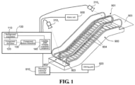
- FIG. 1 is a schematic structural diagram of a monitoring system of a passenger conveyor according to a first embodiment of the present invention.
- the monitoring system according to the embodiment shown in FIG. 1 may be used to detect whether a state of a Landing Plate 903 of an escalator 900 is normal, for example, whether displacement or missing occurs, in a daily operation condition (including an operation condition with passengers and a no-load operation condition without passengers) of a passenger conveyor, wherein the landing plates 903 are usually fixed in an entry/exit region 901 at a first end of the escalator 900 and an entry/exit region 902 at a second end of the escalator 900. If the landing plate 903 is displaced or missing, a passenger is easily caught in the escalator 900, thus causing a major safety accident.
- the monitoring system in the embodiment shown in FIG. 1 specifically includes a sensing apparatus 310 and a processing apparatus 100 coupled to the sensing apparatus 310, and the escalator 900 includes a passenger conveyor controller 910, a driving part 920 such as a motor, and an alarm unit 930.
- the sensing apparatus 310 is specifically an imaging sensor or a depth sensing sensor, or a combination thereof. According to a specific requirement and a monitoring range of a sensor, the escalator 900 may be provided with one or more sensing apparatuses 310, for example, 310 1 to 310 n , N being an integer greater than or equal to 1.
- the sensing apparatus 310 is mounted in such a manner that it can clearly and accurately acquire a monitored object of the escalator 900, and the specific mounting manner and mounting position thereof are not limited.
- sensing apparatuses 310 which are disposed approximately above entry/exit regions (901 and 902) at two ends of the escalator 900 respectively, to sense landing plates 903 in the entry/exit regions (901 and 902). It should be understood that, to accurately sense the landing plate 903, an imaging sensor or a depth sensing sensor of a corresponding type may be selected according to a specific application environment, and even corresponding lighting lamps or the like may be configured above the entry/exit regions (901 and 902).
- the sensing apparatus 310 may be an imaging sensor of a 2D image sensor of various types. It should be understood that, any image sensor capable of capturing an image frame including pixel brightness information can be applied herein. Certainly, an image sensor capable of capturing an image frame including pixel brightness information and color information (such as RGB information) may also be applied herein.
- the sensing apparatus 310 may be any 1D, 2D, or 3D depth sensor or a combination thereof. Such a sensor is operable in an optical, electromagnetic, or acoustic spectrum that can generate a depth map (which is also known as a point cloud or an occupancy grid) of a corresponding dimension.
- a depth map which is also known as a point cloud or an occupancy grid
- Various depth sensing sensor technologies and devices include, but are not limited to: structured light measurement, phase shift measurement, time-of-flight measurement, a stereo triangulation device, an optical triangulation device plate, a light field camera, a coded aperture camera, a computational imaging technology, simultaneous localization and map-building (SLAM), an imaging radar, an imaging sonar, an echolocation device, a scanning LIDAR, a flashing LIDAR, a passive infrared (PIR) sensor, and a small focal plane array (FPA), or a combination including at least one of the foregoing.
- SLAM simultaneous localization and map-building
- PIR passive infrared
- FPA small focal plane array
- Different technologies may include active (transmitting and receiving signals) or passive (only receiving signals) technologies and are operable in a band of an electromagnetic or acoustic spectrum (such as visual and infrared).
- Depth sensing can achieve a particular advantage over conventional 2D imaging.
- the use of infrared sensing can achieve a particular benefit over visible spectrum imaging such that alternatively or additionally, the sensor can be an infrared sensor having one or more pixel spatial resolutions, for example, a passive infrared (PIR) sensor or a small IR focal plane array (FPA).
- PIR passive infrared
- FPA small IR focal plane array
- a 2D imaging sensor such as a conventional monitoring camera
- 1D, 2D or 3D depth sensing sensor there may be qualitative and quantitative differences between a 2D imaging sensor (such as a conventional monitoring camera) and the 1D, 2D or 3D depth sensing sensor to the extent that the depth sensing provides numerous advantages.
- 2D imaging reflected color (a mixture of wavelengths) from the first object in each radial direction of the imager is captured.
- a 2D image may include a combined spectrum of source lighting and a spectral reflectivity of an object in a scene. The 2D image may be roughly interpreted as a picture by a person.
- the 1D, 2D or 3D depth sensing sensor there is no color (spectrum) information.
- a distance (depth, range) to a first reflection object in a radial direction (1D) or directions (2D, 3D) from the sensor is captured.
- the 1D, 2D and 3D technologies may have inherent maximum detectable range limits and may have relatively lower spatial resolution than typical 2D imagers.
- the use of 1D, 2D, or 3D depth sensing may advantageously provide improved operations, and better separation and better privacy protection of shielded objects.
- the use of infrared sensing can achieve a particular benefit over visible spectrum imaging.
- a 2D image cannot be converted into a depth map, and a depth map does not have a capability of being converted into a 2D image (for example, artificial allocation of continuous colors or brightness to continuous depths may cause a person to roughly interpret a depth map in a manner somewhat akin to how a person sees a 2D image, while the depth map is not an image in a conventional sense).
- the sensing apparatus 310 may be an RGB-D sensor, which may simultaneously acquire RGB information and depth (D) information.
- the sensing apparatus 310 senses the landing plate 903 of the escalator 900 in real time and obtains multiple data frames, that is, sequence frames; if the sequence frames are acquired through sensing by the imaging sensor, the sequence frames are multiple image frames, and each pixel therein has, for example, corresponding brightness information and color information; if the sequence frames are acquired through sensing by the depth sensing sensor, the sequence frames are multiple depth maps, and each pixel or occupancy grid therein also has a corresponding depth dimension (reflecting depth information).
- multiple sensing apparatuses 310 1 to 310 n all work simultaneously to acquire corresponding sequence frames, and each frame is transmitted to the processing apparatus 100.
- the processing apparatus 100 is responsible for analyzing each frame, and finally obtains information indicating whether the landing plate 903 of the escalator 900 is in a normal state, for example, determine whether displacement or missing occurs.
- the processing apparatus 100 is configured to include a background acquisition module 110 and a foreground detection module 120.
- the background acquisition module 110 obtains one or more 2D images or 3D depth maps in a no-load normal operation condition (that is, in the absence of passengers) of the escalator 900, and calculates a background based on the 2D images or 3D depth maps. Therefore, the background acquisition module 110 acquires a background model by learning sequence frames acquired when it is determined that the escalator 900 is in a no-load normal state.
- the background model may be established at an initialization stage of the monitoring system, that is, the system is initialized before the landing plate in the daily operation condition is monitored, to obtain a background model.
- the background model may be established through learning by using, but not limited to, a Gaussian Mixture Model, a Code Book Model, Robust Principle Components Analysis (RPCA), and the like.
- a background model obtained by learning image frames acquired by the imaging sensor is a typical brightness background model or chromaticity background model; a background model obtained by learning frames acquired by the depth sensing sensor is a typical depth background model.
- the background model may be adaptively updated.
- a corresponding background model may be acquired again by means of learning at the initialization stage.
- the foreground detection module 120 is configured to compare a data frame acquired in real time with the background model to obtain a foreground object; in most cases, the foreground object is correspondingly a passenger or an article carried by the passenger. Certainly, if the landing plate 903 is displaced or missing, a foreground obtained by comparing a portion of the data frame corresponding to the landing plate 903 with a corresponding portion of the background model also includes a feature reflecting that the landing plate 903 is displaced or missing.
- the comparison process if an imaging sensor is used, the data frame is a 2D image, and the background model is also formed based on the 2D image; the comparison process specifically may be differential processing, for example, a pixel of the 2D image is compared with a corresponding pixel of the background model to calculate a difference (such as a brightness difference). When the difference is greater than a predetermined value, the pixel is retained. Therefore, a foreground object can be obtained. If a depth sensing sensor is used, the data frame is a depth map, and the background model is also formed based on the 3D depth map.
- an occupancy grid in the depth map may be compared with a corresponding occupancy grid of the background model (for example, a depth difference is calculated), and when the difference is greater than a predetermined value, depth information of the occupancy grid is retained (indicating that the occupancy grid is). Therefore, a foreground object can be obtained.
- the foreground detection module 120 may eliminate noise of the foreground object by using some filtering technologies. For example, noise is eliminated by using erosion and dilation image processing technologies, so that the foreground object is obtained more accurately.
- the filtering may include convolution about a spatial, temporal, or spatial-temporal kernel.
- differential processing between a current depth map and the background model includes calculating a difference or distance between features (such as the centroid of cluster features or separate hyperplanes) of the current depth map and the background model, wherein the distance may be calculated by means of Minkowski-p distance measurement, Uncentered Pearson Correlation, or other methods.
- the processing apparatus 100 further includes a foreground feature extraction module 130.
- the foreground feature extraction module 130 extracts a corresponding foreground feature from the foreground object.
- the extracted foreground feature includes features such as the shape and size of the foreground object, and may even include features such as the color and/or position.
- the color feature is embodied by the chromaticity of pixels of the foreground object
- the shape, size and position features are embodied by brightness value changes of the pixels in the foreground object.
- the shape, size and position features are embodied by depth value changes of occupancy grids in the foreground object.
- the position feature extracted by the foreground feature extraction module 130 is a 3D position feature.
- the extracted feature may be a shape feature or other features.
- the shape feature may be, for example, a histogram of oriented gradients (HoG), a Zernike moment, Centroid Invariance to boundary point distribution, Contour Curvature, or the like.
- HoG histogram of oriented gradients
- the foreground feature extraction module may extract other features to provide additional information for shape (or morphological) matching or filtering.
- features may include, but are not limited to: features such as Scale Invariant Feature Transform (SIFT), a Speed-Up Robust Feature (SURF) algorithm, Affine Scale Invariant Feature Transform (ASIFT), other SIFT variables, Harris Corner Detector, a Smallest Univalue Segment Assimilating Nucleus (SUSAN) algorithm, Features from Accelerated Segment Test (FAST) corner detection, Phase Correlation, a Normalized Cross-Correlation, Gradient Location Orientation Histogram (GLOH) algorithm, a Binary Robust Independent Elementary Features (BRIEF) algorithm, a Center Surround Extremas (CenSure/STAR) algorithm, and Oriented and Rotated BRIEF (ORB) algorithm.
- the foreground feature extraction module may further extract a color, a color histogram, an edge histogram, and so on.
- the processing apparatus 100 further includes a landing plate working condition judgment module 140.
- the working condition judgment module 140 judges whether the landing plate 903 is in a normal state based on the foreground feature. Specifically, comparison judgment is performed on the foreground feature by using the background model. For example, by comparing the shape, size and position features of the foreground object with shape, size and position features about the landing plate in the background model, it is judged whether the landing plate is displaced or missing; or by comparing the shape, size, position and color features of the foreground object with shape, size, position and color features about the landing plate in the background model, it is judged whether the landing plate is missing or displaced.
- the shape, size and color feature information about the landing plate in the background model may be implemented in the background acquisition module 110. If the foreground feature is a foreground feature of a foreground object of a passenger, when the foreground feature is compared with the feature information about the landing plate 903 in the background model, it is judged that the foreground feature is unrelated to the landing plate 903, and the landing plate working condition judgment module 140 can easily judge that the landing plate 903 is in a normal state.
- the features used by the landing plate working condition judgment module may be compared or classified as a particular shape, wherein one or more of the following technologies are used: clustering, Deep Learning, Convolutional Neural Networks, Recursive Neural Networks), Dictionary Learning, Bag of visual words, Support Vector Machine (SVM), Decision Trees, Fuzzy Logic, and the like.
- a difference between features may be determined by using one or more of the following methods: Bayesian inference, Markov Model techniques, Hidden Markov Models (HMM), Markov Decision Processes (MDP), Partially Observable MDPs (MPD), Markov Decision Logic, Probabilistic Programming, Deep Learning, Neural Networks, Convolutional Neural Networks, Recursive Neural Networks, Dictionary Learning, Bag of visual words, Support Vector Machine (SVM), Decision Trees, Fuzzy Logic, and the like.
- Bayesian inference Markov Model techniques
- HMM Hidden Markov Models
- MDP Markov Decision Processes
- MPD Partially Observable MDPs
- Markov Decision Logic Probabilistic Programming, Deep Learning, Neural Networks, Convolutional Neural Networks, Recursive Neural Networks, Dictionary Learning, Bag of visual words, Support Vector Machine (SVM), Decision Trees, Fuzzy Logic, and the like.
- the acquired foreground object may include a 2D image of an object after the landing plate 903 is open, and based on the 2D image of the object, features such as the position, size and shape of the object are also extracted, which are further compared with the background model, for example, features such as shapes and sizes corresponding to the same position are compared. Therefore, it can be judged that a particular position lacks a landing plate, thus directly judging that the landing plate is missing.
- the acquired foreground object may include a depth map of an object after the position of the landing plate is open, and based on the depth map of the object, features such as the position, size and 3D shape of the object are also extracted, which are further compared with the background model, for example, features such as sizes and 3D shapes corresponding to the same position are compared. Therefore, it can be judged that a particular position lacks a landing plate, thus directly judging that the landing plate is missing.
- the landing plate working condition judgment module 140 of the processing apparatus 100 if it is judged, according to the features such as the shape and size of the acquired foreground object, that the foreground object is a passenger or an article carried by the passenger, and it is judged, according to the position feature of the acquired foreground object, that the passenger or the article carried by the passenger is on the landing plate 903, considering that an image or a depth map of the landing plate 903 (a portion not shielded by the passenger or the article carried by the passenger) may be relatively obscure and it is relatively difficult to extract features of the corresponding foreground object (if displacement or missing occurs) based on the landing plate 903 in the unshielded portion, the landing plate working condition judgment module 140 may give up judgment on the current data frame or give up the judgment result and proceed to data processing on the next data frame, till it is judged, according to the position feature of the acquired foreground object, that the passenger or the article carried by the passenger is not on the landing plate 903, and a judgment result based on
- the passenger may be acquired as a foreground object, and at the same time, the corresponding features are also extracted; the landing plate working condition judgment module 140 may judge that the foreground object is a passenger based on the DPM technology and the extracted features.
- the data frame acquired by the sensing apparatus 310 is, in fact, basically the same as the data frame for calculating the background model (if the landing plate 903 is not displaced or missing).
- the landing plate working condition judgment module 140 may directly determine that the monitored object is in a normal state, and does not need to make judgment based on the foreground feature extracted by the foreground feature extraction module 130.
- the landing plate working condition judgment module 140 may be configured as follows: only when the judgment result based on multiple continuous adjacent data frames is that the landing plate 903 is in a same abnormal state (such as missing), does the landing plate working condition judgment module 140 determine that the current landing plate 903 is in the abnormal state, which helps improve the judgment accuracy.
- adjacent frames are defined as any two frames in a temporary sequence, but are not limited to immediately successive frames.
- a speed of an object in the adjacent frames may be determined based on timestamps of the frames or based on an average frame time and the count of successive frames between adjacent frames.
- a corresponding signal may be sent to the passenger conveyor controller 910 of the escalator 900, so that corresponding measures are taken.
- the controller 910 further sends a signal to the driving part 920 to reduce a step running speed, or sends a signal to a braking part (not shown in the figure) to perform braking.
- the processing apparatus 100 may further send a signal to an alarm unit 930 mounted above the escalator 900, to remind the passenger to watch out, for example, a message such as "the landing plate is moving; please do not step on the landing plate" is broadcast.
- the processing apparatus 100 may further send a signal to an elevator maintenance center of a building, to prompt that on-site processing needs to be performed in time. Measures taken when it is found that the landing plate 903 of the escalator 900 is in an abnormal state are not limited.
- the monitoring system in the embodiment shown in FIG. 1 may automatically monitor the state of the landing plate 903 of the escalator 900 in real time, the monitoring is accurate and abnormal conditions of the landing plate can be found in time, helping prevent safety accidents.
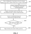
- FIG. 2 A method procedure of landing plate monitoring based on the monitoring system in the embodiment shown in FIG. 1 is illustrated according to FIG. 2 .
- a working principle of the monitoring system according to the embodiment of the present invention is further described with reference to FIG. 1 and FIG. 2 .
- a landing plate of a passenger conveyor is sensed by using an imaging sensor and/or a depth sensing sensor to acquire a data frame.
- the data frame may be acquired through sensing in a no-load normal state (the escalator 900 has no passenger thereon and the landing plate 903 is completely normal); in other cases, the data frame is acquired at any time in a daily operation condition, for example, 30 data frames are acquired per second, and sequence frames in a time period of 5 seconds are acquired at predetermined intervals or acquired continuously, for use in subsequent analysis.
- a background model is acquired based on the data frame sensed in the no-load normal state. This step is accomplished in the background acquisition module 110, and may be implemented at the initialization stage of the system. If both the imaging sensor and the depth sensing sensor are used, background models are acquired by learning separately based on data frames acquired by the imaging sensor and the depth sensing sensor respectively.
- step S13 a data frame sensed in real time is compared with the background model to obtain a foreground object. This step is accomplished in the foreground detection module 120, and the foreground object may be sent to the landing plate working condition judgment module 140 for analysis.
- a corresponding foreground feature is extracted from the foreground object.
- This step is accomplished in the foreground feature extraction module 130, and the extracted foreground feature includes the shape and size of the foreground object, and even further includes information such as color and/or position.
- the color information is embodied through chromaticity of each pixel of the foreground object; the shape, size and position information is embodied through changes in brightness values of pixels in the foreground object.
- the shape, size and position is embodied by changes in depth values of occupancy grids in the foreground object.
- step S 15 it is judged whether the landing plate is in a normal state, and if the judgment result is "no", it indicates that the landing plate 903 is in an abnormal state currently, and step S16 is performed, to trigger alarming and escalator braking operations.
- Step S15 and step S16 are accomplished in the landing plate working condition judgment module. Specifically, comparison judgment may be performed on the foreground feature by using the background model.
- the shape, size and position features of the foreground object For example, by comparing the shape, size and position features of the foreground object with shape, size and position features about the landing plate in the background model, it is judged whether the landing plate is displaced or missing; or by comparing the shape, size, position and color features of the foreground object with shape, size, position and color features about the landing plate in the background model, it is judged whether the landing plate is missing or displaced.
- the shape, size and color feature information about the landing plate in the background model may be implemented in the background acquisition module 110.
- the foreground feature is a foreground feature of a foreground object of a passenger
- the foreground feature is compared with the feature information about the landing plate 903 in the background model, it is judged that the foreground feature is unrelated to the landing plate 903, and the landing plate working condition judgment module 140 can easily judge that the landing plate 903 is in a normal state.
- step S15 considering that an image or a depth map of the landing plate 903 (a portion not shielded by the passenger or the article carried by the passenger) may be relatively obscure and it is relatively difficult to extract features of the corresponding foreground object (if displacement or missing occurs) based on the landing plate 903 in the unshielded portion, the landing plate working condition judgment module 140 may give up judgment on the current data frame or give up the judgment result and proceed to data processing on the next data frame, till it is judged, according to the position feature of the acquired foreground object, that the passenger or the article carried by the passenger is not on the landing plate 903, and a judgment result based on this data frame is used as a
- the data frame acquired by the sensing apparatus 310 is, in fact, basically the same as the data frame for calculating the background model (if the landing plate 903 is not displaced or missing).
- the landing plate 903 is not displaced or missing.
- there is basically no foreground object in the foreground detection module 120 for example, there is only noise information.
- the landing plate working condition judgment module 140 may directly determine that the monitored object is in a normal state, and does not need to make judgment based on the foreground feature extracted by the foreground feature extraction module 130.
- step S15 the process proceeds to step S16 only when judgment results of multiple continuous data frames are "no". In this way, the accuracy of judgment is improved, to prevent misoperation.
- the landing plate monitoring process in the daily operation condition in the foregoing embodiment has basically ended, and this process may be repeated and continuously performed, to continuously monitor the landing plate of the escalator 900.
- the imaging sensor and the depth sensing sensor may separately acquire respective data frames, and in steps S12 to S15, processing is separately performed on the respective data frames; and when the judgment result of the data frame corresponding to either of the imaging sensor and the depth sensing sensor is "no" in step S15, step S16 is performed. In this way, defects of monitoring by either of the imaging sensor and the depth sensing sensor can be avoided, ensuring that the abnormal state of the landing plate is detected timely and reliably.
- FIG. 3 is a schematic structural diagram of a monitoring system of a passenger conveyor according to a second embodiment of the present invention.
- the monitoring system of the embodiment shown in FIG. 3 may be used for monitoring whether a state of a Step 904 of an escalator 900 in a daily operation condition (including an operation condition with passengers and a no-load operation condition without passengers) is normal, for example, whether step missing occurs. If the step 904 is missing and a passenger still takes the escalator 900, a major safety accident occurs easily, and this needs to be completely avoided.
- the monitoring system of the embodiment shown in FIG. 3 specifically includes a sensing apparatus 310 and a processing apparatus 200 coupled to the sensing apparatus 310.
- the escalator 900 includes a passenger conveyor controller 910, a driving part 920 such as a motor, and an alarm unit 930.
- the sensing apparatus 310 is specifically an imaging sensor or a depth sensing sensor, or a combination thereof. According to a specific requirement and a monitoring range of a sensor, the escalator 900 may be provided with one or more sensing apparatuses 310, for example, 310 1 to 310 n , N being an integer greater than or equal to 1.
- the sensing apparatus 310 is mounted in such a manner that it can clearly and accurately acquire a monitored object of the escalator 900, and the specific mounting manner and mounting position thereof are not limited. In this embodiment, there may be one or two sensing apparatuses 310, which are mounted approximately right above a section of steps 904 of the escalator 900. It should be understood that, to accurately sense the steps 904, an imaging sensor or a depth sensing sensor of a corresponding type may be selected according to a specific application environment, and even corresponding lighting lamps or the like may be configured above a section of the steps 904.
- sensing apparatus 310 Specific arrangement of the sensing apparatus 310 is completely the same as that in the embodiment shown in FIG. 1 , and descriptions thereof are omitted here.
- the sensing apparatus 310 senses the step 904 of the escalator 900 in real time and obtains multiple data frames, that is, sequence frames; if the sequence frames are acquired through sensing by the imaging sensor, the sequence frames are multiple image frames, and each pixel therein has, for example, corresponding brightness information and color information; if the sequence frames are acquired through sensing by the depth sensing sensor, the sequence frames are multiple depth maps, and each pixel or occupancy grid therein also has a corresponding depth dimension (reflecting depth information).
- multiple sensing apparatuses 310 1 to 310 n all work simultaneously to acquire corresponding sequence frames, and each frame is transmitted to the processing apparatus 200.
- the processing apparatus 200 is responsible for analyzing each frame, and finally obtains information indicating whether the step 904 of the escalator 900 is in a normal state, for example, determine whether step missing occurs.
- the processing apparatus 200 is configured to include a background acquisition module 210 and a foreground detection module 220.
- the background acquisition module 210 obtains one or more 2D images or 3D depth maps in a no-load normal operation condition (that is, in the absence of passengers) of the escalator 900, and calculates a background based on the 2D images or 3D depth maps. Therefore, the background acquisition module 210 acquires a background model by learning sequence frames acquired when it is determined that the escalator 900 is in a no-load normal state.
- the background model may be established at an initialization stage of the monitoring system, that is, the system is initialized before the step in the daily operation condition is monitored, to obtain a background model.
- the background model may be established through learning by using, but not limited to, a Gaussian Mixture Model, a Code Book Model, Robust Principle Components Analysis (RPCA), and the like.
- a background model obtained by learning image frames acquired by the imaging sensor is a typical brightness background model or chromaticity background model; a background model obtained by learning frames acquired by the depth sensing sensor is a typical depth background model.
- the background model may be adaptively updated.
- a corresponding background model may be acquired again by means of learning at the initialization stage.
- the foreground detection module 220 is configured to compare a data frame acquired in real time with the background model to obtain a foreground object; for example, a differential method is used to obtain the foreground object. In most cases, the foreground object is correspondingly a passenger or an article carried by the passenger. Certainly, if the step 904 is missing, a foreground obtained by comparing a portion of the data frame corresponding to the step 904 with a corresponding portion of the background model also includes a feature reflecting that the step 904 is missing.
- the comparison process if an imaging sensor is used, the data frame is a 2D image, and the background model is also formed based on the 2D image; the comparison process specifically may be differential processing, for example, a pixel of the 2D image is compared with a corresponding pixel of the background model to calculate a difference (such as a brightness difference). When the difference is greater than a predetermined value, the pixel is retained. Therefore, a foreground object can be obtained. If a depth sensing sensor is used, the data frame is a depth map, and the background model is also formed based on the 3D depth map.
- an occupancy grid in the depth map may be compared with a corresponding occupancy grid of the background model (for example, a depth difference is calculated), and when the difference is greater than a predetermined value, depth information of the occupancy grid is retained (indicating that the occupancy grid is). Therefore, a foreground object can be obtained.
- the foreground detection module 220 may eliminate noise of the foreground object by using some filtering technologies. For example, noise is eliminated by using erosion and dilation image processing technologies, so that the foreground object is obtained more accurately.
- the processing apparatus 200 further includes a foreground feature extraction module 230.
- the foreground feature extraction module 230 extracts a corresponding foreground feature from the foreground object.
- the extracted foreground feature includes the shape and size of the foreground object, and may even include information such as the color and/or position.
- the color information is embodied by the chromaticity of pixels of the foreground object
- the shape, size and position information is embodied by brightness value changes of the pixels in the foreground object.
- the shape, size and position features are embodied by depth value changes of occupancy grids in the foreground object.
- the position feature extracted by the foreground feature extraction module 130 is a 3D position feature.
- the processing apparatus 200 further includes a step working condition judgment module 240.
- the working condition judgment module 240 judges whether the step 904 is in a normal state based on the foreground feature. Specifically, comparison judgment is performed on the foreground feature by using the background model. For example, by comparing the shape, size and position features of the foreground object with shape, size and position features about the step in the background model, it is judged whether the step is missing; or by comparing the shape, size, position and color features of the foreground object with shape, size, position and color features about the step in the background model, it is judged whether the step is missing.
- the shape, size and color feature information about the step in the background model may be implemented in the background acquisition module 210.
- the foreground feature is a foreground feature of a foreground object of a passenger
- the foreground feature is compared with the feature information about the step 904 in the background model, it is judged that the foreground feature is unrelated to the step 904, and the step working condition judgment module 240 can easily judge that the step 904 is in a normal state
- the acquired foreground object may include a 2D image of an object after the step 904 is missing and the position of the step 904 is open, and based on the 2D image of the object, features such as the position, size and shape of the object are also extracted, which are further compared with the background model, for example, features such as shapes and sizes corresponding to the same position are compared. Therefore, it can be judged that a particular position lacks a step, thus directly judging that the step is missing.
- the acquired foreground object may include a depth map of an object after the position of the step is open, and based on the depth map of the object, features such as the position, size and 3D shape of the object are also extracted, which are further compared with the background model, for example, features such as 3D shapes corresponding to the same position are compared. Therefore, it can be judged that a particular position lacks a step, thus directly judging that the step is missing.
- the step working condition judgment module 240 of the processing apparatus 200 if it is judged, according to the features such as the shape and size of the acquired foreground object, that the foreground object is a passenger or an article carried by the passenger, and it is judged, according to the position feature of the acquired foreground object, that the passenger or the article carried by the passenger is on a step 904 of a corresponding region, considering that an image or a depth map of the step 904 in this region (a portion not shielded by the passenger or the article carried by the passenger) may be relatively obscure at present and it is relatively difficult to extract features of the corresponding foreground object (if step missing occurs) based on the step 904 in the unshielded portion, the step working condition judgment module 240 may give up judgment on the current data frame or give up the judgment result and proceed to data processing on the next data frame, the foreground object corresponding to the passenger or the article carried by the passenger does not exist on the step 904 in a corresponding region of the acquired data frame
- the data frame acquired by the sensing apparatus 310 is, in fact, basically the same as the data frame for calculating the background model (if the step 904 is not missing).
- the step working condition judgment module 240 may directly determine that the monitored object is in a normal state, and does not need to make judgment based on the foreground feature extracted by the foreground feature extraction module 230.
- the foreground feature extraction module 230 may directly determine that the monitored object is in a normal state, and does not need to make judgment based on the foreground feature extracted by the foreground feature extraction module 230.
- the step working condition judgment module 240 may be configured to determine, only when judgment results based on multiple (such as two) continuous data frames are that a same step 904 is missing, that the current step 904 is in the abnormal state, which helps improve the judgment accuracy.
- a corresponding signal may be sent to the passenger conveyor controller 910 of the escalator 900, so that corresponding measures are taken.
- the controller 910 further sends a signal to the driving part 920 to reduce running speeds of the escalator and the handrail, or sends a signal to a braking part (not shown in the figure) to perform braking.
- the processing apparatus 200 may further send a signal to an alarm unit 930 mounted above the escalator 900, to remind the passenger to watch out, for example, a message such as "a step is missing; please watch out" is broadcast.
- the processing apparatus 200 may further send a signal to an elevator maintenance center of a building, to prompt that on-site processing needs to be performed in time. Measures taken when it is found that the step 904 of the escalator 900 is in an abnormal state are not limited.
- the monitoring system in the embodiment shown in FIG. 3 may automatically monitor the state of the step 904 of the escalator 900 in real time, the monitoring is accurate and abnormal conditions of the step can be found in time, helping prevent safety accidents.
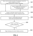
- FIG. 4 A method procedure of step monitoring based on the monitoring system in the embodiment shown in FIG. 3 is illustrated according to FIG. 4 .
- a working principle of the monitoring system according to the embodiment of the present invention is further described with reference to FIG. 3 and FIG. 4 .
- a step of a passenger conveyor is sensed by using an imaging sensor and/or a depth sensing sensor to acquire a data frame.
- the data frame may be acquired through sensing in a no-load normal state (the escalator 900 has no passenger thereon and the step 904 is completely normal); in other cases, the data frame is acquired at any time in a daily operation condition, for example, 30 data frames are acquired per second, and sequence frames in a predetermined time period (for example, a period in which the step turns for a cycle) are acquired at predetermined intervals or acquired continuously, for use in subsequent analysis.
- a background model is acquired based on the data frame sensed in the no-load normal state. This step is accomplished in the background acquisition module 210, and may be implemented at the initialization stage of the system. If both the imaging sensor and the depth sensing sensor are used, background models are acquired by learning separately based on data frames acquired by the imaging sensor and the depth sensing sensor respectively.
- step S23 a data frame sensed in real time is compared with the background model to obtain a foreground object. This step is accomplished in the foreground detection module 220, and the foreground object may be sent to the step working condition judgment module 240 for analysis.
- step S24 a corresponding foreground feature is extracted from the foreground object.
- This step is accomplished in the foreground feature extraction module 230, and the extracted foreground feature includes the shape and size of the foreground object, and even further includes information such as color and/or position.
- step S25 it is judged whether the step is in a normal state, and if the judgment result is "no", it indicates that the step 904 is in an abnormal state currently, and step S26 is performed, to trigger alarming and escalator braking operations.
- Step S25 and step S26 are accomplished in the step working condition judgment module. Specifically, comparison judgment may be performed on the foreground feature by using the background model.
- the shape, size and position features of the foreground object with shape, size and position features about the step in the background model it is judged whether the step is missing; or by comparing the shape, size, position and color features of the foreground object with shape, size, position and color features about the step in the background model, it is judged whether the step is missing or displaced.
- the shape, size and color feature information about the step in the background model may be implemented in the background acquisition module 210.
- the foreground feature is a foreground feature of a foreground object of a passenger
- the foreground feature is compared with the feature information about the step 904 in the background model, it is judged that the foreground feature is unrelated to the step 904, and the step working condition judgment module 240 can easily judge that the step 904 is in a normal state.
- step S25 the process proceeds to step S26 only when judgment results of multiple continuous data frames are "no". In this way, the accuracy of judgment is improved, to prevent misoperation.
- the step monitoring process in the daily operation condition in the foregoing embodiment has basically ended, and this process may be repeated and continuously performed, to continuously monitor the step of the escalator 900.
- the imaging sensor and the depth sensing sensor may separately acquire respective data frames, and in steps S22 to S25, processing is separately performed on the respective data frames; and when the judgment result of the data frame corresponding to either of the imaging sensor and the depth sensing sensor is "no" in step S25, step S26 is performed.
- the process of steps S22 to S25 may be performed on data from the imaging sensor and the depth sensing sensor respectively by using one or more of the following technologies: Bayesian estimation, Maximum likelihood (ML), Maximum a priori (MAP), Non-linear least squares, and the like.
- Bayesian estimation Maximum likelihood (ML)
- MAP Maximum a priori
- Non-linear least squares and the like.
- the processing apparatus (100 or 200) in the monitoring system in the embodiments shown in FIG. 1 and FIG. 3 may be disposed in a control center of a building, or may be integrated with the controller 910 of the escalator 900 or the like, and the specific setting form is not limited.
- more than one monitoring system in the embodiments shown in FIG. 1 and FIG. 3 may be integrated for implementation, and share the sensing apparatus 310, thereby simultaneously monitoring more than one of the landing plate, the step, the barrier used in the maintenance and repair working condition, and the speed of the step, to reduce costs.
Landscapes
- Engineering & Computer Science (AREA)
- Physics & Mathematics (AREA)
- General Physics & Mathematics (AREA)
- Theoretical Computer Science (AREA)
- Computer Vision & Pattern Recognition (AREA)
- Multimedia (AREA)
- Escalators And Moving Walkways (AREA)
Description
- The present invention belongs to the field of passenger conveyor technologies, and relates to automatic monitoring of a passenger conveyor.
- A passenger conveyor (such as an escalators or a moving walkway) is increasingly widely applied in public places such as subways, shopping malls, airports, and the like, and the running safety thereof becomes increasingly important.
- During running of a passenger conveyor, abnormalities such as reverse running, speed anomaly, Step missing, Landing Plate displacement or missing may occur, causing major safety accidents; or during a repair operation of the passenger conveyor, no Barrier is disposed due to a non-standard operation while the passenger conveyor is in a repair running state, and in this case, if a passenger enters the passenger conveyor, a major safety accident also occurs easily.
-
JP2010269884A -
WO2015/171774A1 describes an object detector, and method for controlling a passenger conveyor system using the same. - According to a first aspect of the present invention, a monitoring system of a passenger conveyor is provided according to claim 1.
One or more examples of such a system are provided by claims 2 to 6. - According to another aspect of the present invention, a monitoring method of a passenger conveyor is provided according to claim 7.
One or more examples of such a method are provided by claims 8 to 12. - According to still another aspect of the present invention, a passenger conveying system is provided, including a passenger conveyor and the foregoing monitoring system.
- The foregoing features and operations of the present invention will become more obvious according to the following description and the accompanying drawings.
- The following detailed description with reference to the accompanying drawings will make the foregoing and other objectives and advantages of the present invention more complete and clearer, wherein identical or similar elements are represented using identical reference signs.
-
FIG. 1 is a schematic structural diagram of a monitoring system of a passenger conveyor according to a first embodiment of the present invention; -
FIG. 2 is a schematic flowchart of a monitoring method of a passenger conveyor according to a first embodiment of the present invention; -
FIG. 3 is a schematic structural diagram of a monitoring system of a passenger conveyor according to a second embodiment of the present invention; and -
FIG. 4 is a schematic flowchart of a monitoring method of a passenger conveyor according to a second embodiment of the present invention; - The present invention is now described more completely with reference to the accompanying drawings. Exemplary embodiments of the present invention are illustrated in the accompanying drawings. However, the present invention may be implemented in lots of different forms, and should not be understood as being limited to the embodiments described herein. On the contrary, the embodiments are provided to make the disclosure thorough and complete, and fully convey the concept of the present invention to those skilled in the art. In the accompanying drawings, identical reference signs represent identical elements or parts, and therefore, descriptions thereof are omitted.
- Some block diagrams in the accompanying drawings are functional entities, which do not necessarily correspond to physically or logically independent entities. These functional entities may be implemented in a software form, or implemented in one or more hardware modules or integrated circuits, or in different processing apparatuses and/or microcontroller apparatuses.
- In the present invention, passenger conveyors include Escalators and Moving Walkways. In the embodiments illustrated below, an escalator is used as an example to describe the monitoring system and monitoring method of the embodiments of the present invention in detail. However, it should be understood that, the monitoring system and monitoring method for the escalator in the following embodiments may also be analogically applied to moving walkways. Adaptive improvements or the like that may need to be performed can be obtained by those skilled in the art with the teachings of the embodiments of the present invention.
- It should be noted that, in the present invention, a "normal state" of a monitored object of the passenger conveyor refers to a working condition state in which the monitored object at least does not bring potential safety hazards to passengers; on the contrary, an "abnormal state" refers to a working condition state in which the monitored object at least may bring potential safety hazards to passengers, for example, a working condition state that does not conform to related standards or regulations. Those skilled in the art may define the "normal state" and "abnormal state" in advance according to a specific application environment and a specific monitored object.
-
FIG. 1 is a schematic structural diagram of a monitoring system of a passenger conveyor according to a first embodiment of the present invention. The monitoring system according to the embodiment shown inFIG. 1 may be used to detect whether a state of aLanding Plate 903 of anescalator 900 is normal, for example, whether displacement or missing occurs, in a daily operation condition (including an operation condition with passengers and a no-load operation condition without passengers) of a passenger conveyor, wherein thelanding plates 903 are usually fixed in an entry/exit region 901 at a first end of theescalator 900 and an entry/exit region 902 at a second end of theescalator 900. If thelanding plate 903 is displaced or missing, a passenger is easily caught in theescalator 900, thus causing a major safety accident. - The monitoring system in the embodiment shown in
FIG. 1 specifically includes asensing apparatus 310 and aprocessing apparatus 100 coupled to thesensing apparatus 310, and theescalator 900 includes apassenger conveyor controller 910, adriving part 920 such as a motor, and analarm unit 930. - The
sensing apparatus 310 is specifically an imaging sensor or a depth sensing sensor, or a combination thereof. According to a specific requirement and a monitoring range of a sensor, theescalator 900 may be provided with one or moresensing apparatuses 310, for example, 3101 to 310n, N being an integer greater than or equal to 1. Thesensing apparatus 310 is mounted in such a manner that it can clearly and accurately acquire a monitored object of theescalator 900, and the specific mounting manner and mounting position thereof are not limited. In this embodiment, there are twosensing apparatuses 310, which are disposed approximately above entry/exit regions (901 and 902) at two ends of theescalator 900 respectively, to senselanding plates 903 in the entry/exit regions (901 and 902). It should be understood that, to accurately sense thelanding plate 903, an imaging sensor or a depth sensing sensor of a corresponding type may be selected according to a specific application environment, and even corresponding lighting lamps or the like may be configured above the entry/exit regions (901 and 902). - The
sensing apparatus 310 may be an imaging sensor of a 2D image sensor of various types. It should be understood that, any image sensor capable of capturing an image frame including pixel brightness information can be applied herein. Certainly, an image sensor capable of capturing an image frame including pixel brightness information and color information (such as RGB information) may also be applied herein. - The
sensing apparatus 310 may be any 1D, 2D, or 3D depth sensor or a combination thereof. Such a sensor is operable in an optical, electromagnetic, or acoustic spectrum that can generate a depth map (which is also known as a point cloud or an occupancy grid) of a corresponding dimension. Various depth sensing sensor technologies and devices include, but are not limited to: structured light measurement, phase shift measurement, time-of-flight measurement, a stereo triangulation device, an optical triangulation device plate, a light field camera, a coded aperture camera, a computational imaging technology, simultaneous localization and map-building (SLAM), an imaging radar, an imaging sonar, an echolocation device, a scanning LIDAR, a flashing LIDAR, a passive infrared (PIR) sensor, and a small focal plane array (FPA), or a combination including at least one of the foregoing. Different technologies may include active (transmitting and receiving signals) or passive (only receiving signals) technologies and are operable in a band of an electromagnetic or acoustic spectrum (such as visual and infrared). Depth sensing can achieve a particular advantage over conventional 2D imaging. The use of infrared sensing can achieve a particular benefit over visible spectrum imaging such that alternatively or additionally, the sensor can be an infrared sensor having one or more pixel spatial resolutions, for example, a passive infrared (PIR) sensor or a small IR focal plane array (FPA). - It should be noted that, there may be qualitative and quantitative differences between a 2D imaging sensor (such as a conventional monitoring camera) and the 1D, 2D or 3D depth sensing sensor to the extent that the depth sensing provides numerous advantages. In 2D imaging, reflected color (a mixture of wavelengths) from the first object in each radial direction of the imager is captured. A 2D image, then, may include a combined spectrum of source lighting and a spectral reflectivity of an object in a scene. The 2D image may be roughly interpreted as a picture by a person. In the 1D, 2D or 3D depth sensing sensor, there is no color (spectrum) information. More specifically, a distance (depth, range) to a first reflection object in a radial direction (1D) or directions (2D, 3D) from the sensor is captured. The 1D, 2D and 3D technologies may have inherent maximum detectable range limits and may have relatively lower spatial resolution than typical 2D imagers. In terms of relative immunity to ambient lighting problems, compared to conventional 2D imaging, the use of 1D, 2D, or 3D depth sensing may advantageously provide improved operations, and better separation and better privacy protection of shielded objects. The use of infrared sensing can achieve a particular benefit over visible spectrum imaging. For example, it is possible that a 2D image cannot be converted into a depth map, and a depth map does not have a capability of being converted into a 2D image (for example, artificial allocation of continuous colors or brightness to continuous depths may cause a person to roughly interpret a depth map in a manner somewhat akin to how a person sees a 2D image, while the depth map is not an image in a conventional sense).
- When the
sensing apparatus 310 is specifically a combination of an imaging sensor and a depth sensing sensor, thesensing apparatus 310 may be an RGB-D sensor, which may simultaneously acquire RGB information and depth (D) information. - The
sensing apparatus 310 senses thelanding plate 903 of theescalator 900 in real time and obtains multiple data frames, that is, sequence frames; if the sequence frames are acquired through sensing by the imaging sensor, the sequence frames are multiple image frames, and each pixel therein has, for example, corresponding brightness information and color information; if the sequence frames are acquired through sensing by the depth sensing sensor, the sequence frames are multiple depth maps, and each pixel or occupancy grid therein also has a corresponding depth dimension (reflecting depth information). - If it is necessary to monitor the
landing plate 903 all the time, in both the operation condition with passengers and the no-load operation condition without passengers,multiple sensing apparatuses 3101 to 310n all work simultaneously to acquire corresponding sequence frames, and each frame is transmitted to theprocessing apparatus 100. Theprocessing apparatus 100 is responsible for analyzing each frame, and finally obtains information indicating whether thelanding plate 903 of theescalator 900 is in a normal state, for example, determine whether displacement or missing occurs. - Specifically, the
processing apparatus 100 is configured to include abackground acquisition module 110 and aforeground detection module 120. Thebackground acquisition module 110 obtains one or more 2D images or 3D depth maps in a no-load normal operation condition (that is, in the absence of passengers) of theescalator 900, and calculates a background based on the 2D images or 3D depth maps. Therefore, thebackground acquisition module 110 acquires a background model by learning sequence frames acquired when it is determined that theescalator 900 is in a no-load normal state. The background model may be established at an initialization stage of the monitoring system, that is, the system is initialized before the landing plate in the daily operation condition is monitored, to obtain a background model. The background model may be established through learning by using, but not limited to, a Gaussian Mixture Model, a Code Book Model, Robust Principle Components Analysis (RPCA), and the like. A background model obtained by learning image frames acquired by the imaging sensor is a typical brightness background model or chromaticity background model; a background model obtained by learning frames acquired by the depth sensing sensor is a typical depth background model. - It should be understood that, at the subsequent landing plate monitoring stage, the background model may be adaptively updated. When an application scenario, a sensor type, or a setting changes, a corresponding background model may be acquired again by means of learning at the initialization stage.
- The
foreground detection module 120 is configured to compare a data frame acquired in real time with the background model to obtain a foreground object; in most cases, the foreground object is correspondingly a passenger or an article carried by the passenger. Certainly, if thelanding plate 903 is displaced or missing, a foreground obtained by comparing a portion of the data frame corresponding to thelanding plate 903 with a corresponding portion of the background model also includes a feature reflecting that thelanding plate 903 is displaced or missing. Specifically, in the comparison process, if an imaging sensor is used, the data frame is a 2D image, and the background model is also formed based on the 2D image; the comparison process specifically may be differential processing, for example, a pixel of the 2D image is compared with a corresponding pixel of the background model to calculate a difference (such as a brightness difference). When the difference is greater than a predetermined value, the pixel is retained. Therefore, a foreground object can be obtained. If a depth sensing sensor is used, the data frame is a depth map, and the background model is also formed based on the 3D depth map. For example, an occupancy grid in the depth map may be compared with a corresponding occupancy grid of the background model (for example, a depth difference is calculated), and when the difference is greater than a predetermined value, depth information of the occupancy grid is retained (indicating that the occupancy grid is). Therefore, a foreground object can be obtained. - In an embodiment, the
foreground detection module 120 may eliminate noise of the foreground object by using some filtering technologies. For example, noise is eliminated by using erosion and dilation image processing technologies, so that the foreground object is obtained more accurately. It should be noted that, the filtering may include convolution about a spatial, temporal, or spatial-temporal kernel. - When the foregoing comparison is differential processing, it should be noted that, differential processing between a current depth map and the background model includes calculating a difference or distance between features (such as the centroid of cluster features or separate hyperplanes) of the current depth map and the background model, wherein the distance may be calculated by means of Minkowski-p distance measurement, Uncentered Pearson Correlation, or other methods.
- According to the invention, the
processing apparatus 100 further includes a foregroundfeature extraction module 130. The foregroundfeature extraction module 130 extracts a corresponding foreground feature from the foreground object. In order to monitor the landing plate of theescalator 900, the extracted foreground feature includes features such as the shape and size of the foreground object, and may even include features such as the color and/or position. Taking the data frame acquired by the imaging sensor as an example, the color feature is embodied by the chromaticity of pixels of the foreground object, and the shape, size and position features are embodied by brightness value changes of the pixels in the foreground object. Taking the data frame acquired by the depth sensing sensor as an example, the shape, size and position features are embodied by depth value changes of occupancy grids in the foreground object. - It should be noted that, for the position feature, if the data frame is acquired by the depth sensing sensor, the position feature extracted by the foreground
feature extraction module 130 is a 3D position feature. - It should be noted that, in this embodiment or the following embodiments, the extracted feature (descriptor) may be a shape feature or other features. The shape feature may be, for example, a histogram of oriented gradients (HoG), a Zernike moment, Centroid Invariance to boundary point distribution, Contour Curvature, or the like. The foreground feature extraction module may extract other features to provide additional information for shape (or morphological) matching or filtering. For example, other features may include, but are not limited to: features such as Scale Invariant Feature Transform (SIFT), a Speed-Up Robust Feature (SURF) algorithm, Affine Scale Invariant Feature Transform (ASIFT), other SIFT variables, Harris Corner Detector, a Smallest Univalue Segment Assimilating Nucleus (SUSAN) algorithm, Features from Accelerated Segment Test (FAST) corner detection, Phase Correlation, a Normalized Cross-Correlation, Gradient Location Orientation Histogram (GLOH) algorithm, a Binary Robust Independent Elementary Features (BRIEF) algorithm, a Center Surround Extremas (CenSure/STAR) algorithm, and Oriented and Rotated BRIEF (ORB) algorithm. The foreground feature extraction module may further extract a color, a color histogram, an edge histogram, and so on.
- Further, the
processing apparatus 100 further includes a landing plate workingcondition judgment module 140. The workingcondition judgment module 140 judges whether thelanding plate 903 is in a normal state based on the foreground feature. Specifically, comparison judgment is performed on the foreground feature by using the background model. For example, by comparing the shape, size and position features of the foreground object with shape, size and position features about the landing plate in the background model, it is judged whether the landing plate is displaced or missing; or by comparing the shape, size, position and color features of the foreground object with shape, size, position and color features about the landing plate in the background model, it is judged whether the landing plate is missing or displaced. It should be noted that, the shape, size and color feature information about the landing plate in the background model may be implemented in thebackground acquisition module 110. If the foreground feature is a foreground feature of a foreground object of a passenger, when the foreground feature is compared with the feature information about thelanding plate 903 in the background model, it is judged that the foreground feature is unrelated to thelanding plate 903, and the landing plate workingcondition judgment module 140 can easily judge that thelanding plate 903 is in a normal state. - In this embodiment or other embodiments, the features used by the landing plate working condition judgment module may be compared or classified as a particular shape, wherein one or more of the following technologies are used: clustering, Deep Learning, Convolutional Neural Networks, Recursive Neural Networks), Dictionary Learning, Bag of visual words, Support Vector Machine (SVM), Decision Trees, Fuzzy Logic, and the like.
- It should be noted that, in this embodiment or other embodiments, during comparison, a difference between features may be determined by using one or more of the following methods: Bayesian inference, Markov Model techniques, Hidden Markov Models (HMM), Markov Decision Processes (MDP), Partially Observable MDPs (MPD), Markov Decision Logic, Probabilistic Programming, Deep Learning, Neural Networks, Convolutional Neural Networks, Recursive Neural Networks, Dictionary Learning, Bag of visual words, Support Vector Machine (SVM), Decision Trees, Fuzzy Logic, and the like.
- Taking landing plate missing in 2D image processing as an example, the acquired foreground object may include a 2D image of an object after the
landing plate 903 is open, and based on the 2D image of the object, features such as the position, size and shape of the object are also extracted, which are further compared with the background model, for example, features such as shapes and sizes corresponding to the same position are compared. Therefore, it can be judged that a particular position lacks a landing plate, thus directly judging that the landing plate is missing. - Taking landing plate missing in depth map processing as an example, the acquired foreground object may include a depth map of an object after the position of the landing plate is open, and based on the depth map of the object, features such as the position, size and 3D shape of the object are also extracted, which are further compared with the background model, for example, features such as sizes and 3D shapes corresponding to the same position are compared. Therefore, it can be judged that a particular position lacks a landing plate, thus directly judging that the landing plate is missing.
- It should be noted that, in the landing plate working
condition judgment module 140 of theprocessing apparatus 100, if it is judged, according to the features such as the shape and size of the acquired foreground object, that the foreground object is a passenger or an article carried by the passenger, and it is judged, according to the position feature of the acquired foreground object, that the passenger or the article carried by the passenger is on thelanding plate 903, considering that an image or a depth map of the landing plate 903 (a portion not shielded by the passenger or the article carried by the passenger) may be relatively obscure and it is relatively difficult to extract features of the corresponding foreground object (if displacement or missing occurs) based on thelanding plate 903 in the unshielded portion, the landing plate workingcondition judgment module 140 may give up judgment on the current data frame or give up the judgment result and proceed to data processing on the next data frame, till it is judged, according to the position feature of the acquired foreground object, that the passenger or the article carried by the passenger is not on thelanding plate 903, and a judgment result based on this data frame is used as a monitoring result of thelanding plate 903. Taking a passenger being sensed as an example, the passenger may be acquired as a foreground object, and at the same time, the corresponding features are also extracted; the landing plate workingcondition judgment module 140 may judge that the foreground object is a passenger based on the DPM technology and the extracted features. - It should be understood that, in another embodiment, if the monitored escalator is in a no-load normal state, in this case, the data frame acquired by the
sensing apparatus 310 is, in fact, basically the same as the data frame for calculating the background model (if thelanding plate 903 is not displaced or missing). In this case, there is basically no foreground object in the foreground detection module 120 (for example, there is only noise information). At this point, the landing plate workingcondition judgment module 140 may directly determine that the monitored object is in a normal state, and does not need to make judgment based on the foreground feature extracted by the foregroundfeature extraction module 130. - Further, the landing plate working
condition judgment module 140 may be configured as follows: only when the judgment result based on multiple continuous adjacent data frames is that thelanding plate 903 is in a same abnormal state (such as missing), does the landing plate workingcondition judgment module 140 determine that thecurrent landing plate 903 is in the abnormal state, which helps improve the judgment accuracy. - It should be noted that, adjacent frames are defined as any two frames in a temporary sequence, but are not limited to immediately successive frames. A speed of an object in the adjacent frames may be determined based on timestamps of the frames or based on an average frame time and the count of successive frames between adjacent frames.
- When the landing plate working
condition judgment module 140 in theprocessing apparatus 100 in the foregoing embodiment determines that the monitoredlanding plate 903 is in an abnormal state (for example, the landing plate is missing or displaced), a corresponding signal may be sent to thepassenger conveyor controller 910 of theescalator 900, so that corresponding measures are taken. For example, thecontroller 910 further sends a signal to the drivingpart 920 to reduce a step running speed, or sends a signal to a braking part (not shown in the figure) to perform braking. Theprocessing apparatus 100 may further send a signal to analarm unit 930 mounted above theescalator 900, to remind the passenger to watch out, for example, a message such as "the landing plate is moving; please do not step on the landing plate" is broadcast. Certainly, theprocessing apparatus 100 may further send a signal to an elevator maintenance center of a building, to prompt that on-site processing needs to be performed in time. Measures taken when it is found that thelanding plate 903 of theescalator 900 is in an abnormal state are not limited. - The monitoring system in the embodiment shown in
FIG. 1 may automatically monitor the state of thelanding plate 903 of theescalator 900 in real time, the monitoring is accurate and abnormal conditions of the landing plate can be found in time, helping prevent safety accidents. - A method procedure of landing plate monitoring based on the monitoring system in the embodiment shown in
FIG. 1 is illustrated according toFIG. 2 . A working principle of the monitoring system according to the embodiment of the present invention is further described with reference toFIG. 1 andFIG. 2 . - First, in step S11, a landing plate of a passenger conveyor is sensed by using an imaging sensor and/or a depth sensing sensor to acquire a data frame. During acquisition of a background model through learning, the data frame may be acquired through sensing in a no-load normal state (the
escalator 900 has no passenger thereon and thelanding plate 903 is completely normal); in other cases, the data frame is acquired at any time in a daily operation condition, for example, 30 data frames are acquired per second, and sequence frames in a time period of 5 seconds are acquired at predetermined intervals or acquired continuously, for use in subsequent analysis. - Further, in step S 12, a background model is acquired based on the data frame sensed in the no-load normal state. This step is accomplished in the
background acquisition module 110, and may be implemented at the initialization stage of the system. If both the imaging sensor and the depth sensing sensor are used, background models are acquired by learning separately based on data frames acquired by the imaging sensor and the depth sensing sensor respectively. - Further, in step S13, a data frame sensed in real time is compared with the background model to obtain a foreground object. This step is accomplished in the
foreground detection module 120, and the foreground object may be sent to the landing plate workingcondition judgment module 140 for analysis. - Further, in step S14, a corresponding foreground feature is extracted from the foreground object. This step is accomplished in the foreground
feature extraction module 130, and the extracted foreground feature includes the shape and size of the foreground object, and even further includes information such as color and/or position. Taking the data frame acquired by the imaging sensor as an example, the color information is embodied through chromaticity of each pixel of the foreground object; the shape, size and position information is embodied through changes in brightness values of pixels in the foreground object. Taking the data frame acquired by the depth sensing sensor as an example, the shape, size and position is embodied by changes in depth values of occupancy grids in the foreground object. - Further, in
step S 15, it is judged whether the landing plate is in a normal state, and if the judgment result is "no", it indicates that thelanding plate 903 is in an abnormal state currently, and step S16 is performed, to trigger alarming and escalator braking operations. Step S15 and step S16 are accomplished in the landing plate working condition judgment module. Specifically, comparison judgment may be performed on the foreground feature by using the background model. For example, by comparing the shape, size and position features of the foreground object with shape, size and position features about the landing plate in the background model, it is judged whether the landing plate is displaced or missing; or by comparing the shape, size, position and color features of the foreground object with shape, size, position and color features about the landing plate in the background model, it is judged whether the landing plate is missing or displaced. It should be noted that, the shape, size and color feature information about the landing plate in the background model may be implemented in thebackground acquisition module 110. If the foreground feature is a foreground feature of a foreground object of a passenger, when the foreground feature is compared with the feature information about thelanding plate 903 in the background model, it is judged that the foreground feature is unrelated to thelanding plate 903, and the landing plate workingcondition judgment module 140 can easily judge that thelanding plate 903 is in a normal state. - During judgment, if it is judged, according to the features such as the shape and size of the acquired foreground object, that the foreground object is a passenger or an article carried by the passenger, and it is judged, according to the position feature of the acquired foreground object, that the passenger or the article carried by the passenger is on the
landing plate 903, in an embodiment, in step S15, considering that an image or a depth map of the landing plate 903 (a portion not shielded by the passenger or the article carried by the passenger) may be relatively obscure and it is relatively difficult to extract features of the corresponding foreground object (if displacement or missing occurs) based on thelanding plate 903 in the unshielded portion, the landing plate workingcondition judgment module 140 may give up judgment on the current data frame or give up the judgment result and proceed to data processing on the next data frame, till it is judged, according to the position feature of the acquired foreground object, that the passenger or the article carried by the passenger is not on thelanding plate 903, and a judgment result based on this data frame is used as a monitoring result of thelanding plate 903. - In another embodiment, if the monitored escalator is in a no-load normal state, in this case, the data frame acquired by the
sensing apparatus 310 is, in fact, basically the same as the data frame for calculating the background model (if thelanding plate 903 is not displaced or missing). In this case, there is basically no foreground object in the foreground detection module 120 (for example, there is only noise information). At this point, in step S15, the landing plate workingcondition judgment module 140 may directly determine that the monitored object is in a normal state, and does not need to make judgment based on the foreground feature extracted by the foregroundfeature extraction module 130. - In step S15, the process proceeds to step S16 only when judgment results of multiple continuous data frames are "no". In this way, the accuracy of judgment is improved, to prevent misoperation.
- So far, the landing plate monitoring process in the daily operation condition in the foregoing embodiment has basically ended, and this process may be repeated and continuously performed, to continuously monitor the landing plate of the
escalator 900. It should be noted that, if both the imaging sensor and the depth sensing sensor are used, the imaging sensor and the depth sensing sensor may separately acquire respective data frames, and in steps S12 to S15, processing is separately performed on the respective data frames; and when the judgment result of the data frame corresponding to either of the imaging sensor and the depth sensing sensor is "no" in step S15, step S16 is performed. In this way, defects of monitoring by either of the imaging sensor and the depth sensing sensor can be avoided, ensuring that the abnormal state of the landing plate is detected timely and reliably. -
FIG. 3 is a schematic structural diagram of a monitoring system of a passenger conveyor according to a second embodiment of the present invention. The monitoring system of the embodiment shown inFIG. 3 may be used for monitoring whether a state of aStep 904 of anescalator 900 in a daily operation condition (including an operation condition with passengers and a no-load operation condition without passengers) is normal, for example, whether step missing occurs. If thestep 904 is missing and a passenger still takes theescalator 900, a major safety accident occurs easily, and this needs to be completely avoided. - The monitoring system of the embodiment shown in
FIG. 3 specifically includes asensing apparatus 310 and aprocessing apparatus 200 coupled to thesensing apparatus 310. Theescalator 900 includes apassenger conveyor controller 910, a drivingpart 920 such as a motor, and analarm unit 930. - The
sensing apparatus 310 is specifically an imaging sensor or a depth sensing sensor, or a combination thereof. According to a specific requirement and a monitoring range of a sensor, theescalator 900 may be provided with one ormore sensing apparatuses 310, for example, 3101 to 310n, N being an integer greater than or equal to 1. Thesensing apparatus 310 is mounted in such a manner that it can clearly and accurately acquire a monitored object of theescalator 900, and the specific mounting manner and mounting position thereof are not limited. In this embodiment, there may be one or twosensing apparatuses 310, which are mounted approximately right above a section ofsteps 904 of theescalator 900. It should be understood that, to accurately sense thesteps 904, an imaging sensor or a depth sensing sensor of a corresponding type may be selected according to a specific application environment, and even corresponding lighting lamps or the like may be configured above a section of thesteps 904. - Specific arrangement of the
sensing apparatus 310 is completely the same as that in the embodiment shown inFIG. 1 , and descriptions thereof are omitted here. - The
sensing apparatus 310 senses thestep 904 of theescalator 900 in real time and obtains multiple data frames, that is, sequence frames; if the sequence frames are acquired through sensing by the imaging sensor, the sequence frames are multiple image frames, and each pixel therein has, for example, corresponding brightness information and color information; if the sequence frames are acquired through sensing by the depth sensing sensor, the sequence frames are multiple depth maps, and each pixel or occupancy grid therein also has a corresponding depth dimension (reflecting depth information). - If it is necessary to monitor the
step 904 all the time, in both the operation condition with passengers and the no-load operation condition without passengers,multiple sensing apparatuses 3101 to 310n all work simultaneously to acquire corresponding sequence frames, and each frame is transmitted to theprocessing apparatus 200. Theprocessing apparatus 200 is responsible for analyzing each frame, and finally obtains information indicating whether thestep 904 of theescalator 900 is in a normal state, for example, determine whether step missing occurs. - Specifically, the
processing apparatus 200 is configured to include abackground acquisition module 210 and aforeground detection module 220. Thebackground acquisition module 210 obtains one or more 2D images or 3D depth maps in a no-load normal operation condition (that is, in the absence of passengers) of theescalator 900, and calculates a background based on the 2D images or 3D depth maps. Therefore, thebackground acquisition module 210 acquires a background model by learning sequence frames acquired when it is determined that theescalator 900 is in a no-load normal state. The background model may be established at an initialization stage of the monitoring system, that is, the system is initialized before the step in the daily operation condition is monitored, to obtain a background model. The background model may be established through learning by using, but not limited to, a Gaussian Mixture Model, a Code Book Model, Robust Principle Components Analysis (RPCA), and the like. A background model obtained by learning image frames acquired by the imaging sensor is a typical brightness background model or chromaticity background model; a background model obtained by learning frames acquired by the depth sensing sensor is a typical depth background model. - It should be understood that, at the subsequent step monitoring stage, the background model may be adaptively updated. When an application scenario, a sensor type, or a setting changes, a corresponding background model may be acquired again by means of learning at the initialization stage.
- The
foreground detection module 220 is configured to compare a data frame acquired in real time with the background model to obtain a foreground object; for example, a differential method is used to obtain the foreground object. In most cases, the foreground object is correspondingly a passenger or an article carried by the passenger. Certainly, if thestep 904 is missing, a foreground obtained by comparing a portion of the data frame corresponding to thestep 904 with a corresponding portion of the background model also includes a feature reflecting that thestep 904 is missing. Specifically, in the comparison process, if an imaging sensor is used, the data frame is a 2D image, and the background model is also formed based on the 2D image; the comparison process specifically may be differential processing, for example, a pixel of the 2D image is compared with a corresponding pixel of the background model to calculate a difference (such as a brightness difference). When the difference is greater than a predetermined value, the pixel is retained. Therefore, a foreground object can be obtained. If a depth sensing sensor is used, the data frame is a depth map, and the background model is also formed based on the 3D depth map. For example, an occupancy grid in the depth map may be compared with a corresponding occupancy grid of the background model (for example, a depth difference is calculated), and when the difference is greater than a predetermined value, depth information of the occupancy grid is retained (indicating that the occupancy grid is). Therefore, a foreground object can be obtained. - In an embodiment, the
foreground detection module 220 may eliminate noise of the foreground object by using some filtering technologies. For example, noise is eliminated by using erosion and dilation image processing technologies, so that the foreground object is obtained more accurately. - According to the invention, the
processing apparatus 200 further includes a foregroundfeature extraction module 230. The foregroundfeature extraction module 230 extracts a corresponding foreground feature from the foreground object. In order to monitor the step of theescalator 900, the extracted foreground feature includes the shape and size of the foreground object, and may even include information such as the color and/or position. Taking the data frame acquired by the imaging sensor as an example, the color information is embodied by the chromaticity of pixels of the foreground object, and the shape, size and position information is embodied by brightness value changes of the pixels in the foreground object. Taking the data frame acquired by the depth sensing sensor as an example, the shape, size and position features are embodied by depth value changes of occupancy grids in the foreground object. - It should be noted that, for the position feature, if the data frame is acquired by the depth sensing sensor, the position feature extracted by the foreground
feature extraction module 130 is a 3D position feature. - Further, the
processing apparatus 200 further includes a step workingcondition judgment module 240. The workingcondition judgment module 240 judges whether thestep 904 is in a normal state based on the foreground feature. Specifically, comparison judgment is performed on the foreground feature by using the background model. For example, by comparing the shape, size and position features of the foreground object with shape, size and position features about the step in the background model, it is judged whether the step is missing; or by comparing the shape, size, position and color features of the foreground object with shape, size, position and color features about the step in the background model, it is judged whether the step is missing. It should be noted that, the shape, size and color feature information about the step in the background model may be implemented in thebackground acquisition module 210. If the foreground feature is a foreground feature of a foreground object of a passenger, when the foreground feature is compared with the feature information about thestep 904 in the background model, it is judged that the foreground feature is unrelated to thestep 904, and the step workingcondition judgment module 240 can easily judge that thestep 904 is in a normal state - Taking step missing in 2D image processing as an example, the acquired foreground object may include a 2D image of an object after the
step 904 is missing and the position of thestep 904 is open, and based on the 2D image of the object, features such as the position, size and shape of the object are also extracted, which are further compared with the background model, for example, features such as shapes and sizes corresponding to the same position are compared. Therefore, it can be judged that a particular position lacks a step, thus directly judging that the step is missing. - Taking step missing in depth map processing as an example, the acquired foreground object may include a depth map of an object after the position of the step is open, and based on the depth map of the object, features such as the position, size and 3D shape of the object are also extracted, which are further compared with the background model, for example, features such as 3D shapes corresponding to the same position are compared. Therefore, it can be judged that a particular position lacks a step, thus directly judging that the step is missing.
- It should be noted that, in the step working
condition judgment module 240 of theprocessing apparatus 200, if it is judged, according to the features such as the shape and size of the acquired foreground object, that the foreground object is a passenger or an article carried by the passenger, and it is judged, according to the position feature of the acquired foreground object, that the passenger or the article carried by the passenger is on astep 904 of a corresponding region, considering that an image or a depth map of thestep 904 in this region (a portion not shielded by the passenger or the article carried by the passenger) may be relatively obscure at present and it is relatively difficult to extract features of the corresponding foreground object (if step missing occurs) based on thestep 904 in the unshielded portion, the step workingcondition judgment module 240 may give up judgment on the current data frame or give up the judgment result and proceed to data processing on the next data frame, the foreground object corresponding to the passenger or the article carried by the passenger does not exist on thestep 904 in a corresponding region of the acquired data frame, and a judgment result based on this data frame is used as a monitoring result of thestep 904. - It should be understood that, in another embodiment, assuming that the monitored escalator is in a no-load normal state, in this case, the data frame acquired by the
sensing apparatus 310 is, in fact, basically the same as the data frame for calculating the background model (if thestep 904 is not missing). In this case, there is basically no foreground object in the foreground detection module 220 (for example, there is only noise information). At this point, the step workingcondition judgment module 240 may directly determine that the monitored object is in a normal state, and does not need to make judgment based on the foreground feature extracted by the foregroundfeature extraction module 230. Certainly, if there is a foreground object (which is probably caused by step missing), judgment is still made based on the foreground feature extracted by the foregroundfeature extraction module 230. - Further, the step working
condition judgment module 240 may be configured to determine, only when judgment results based on multiple (such as two) continuous data frames are that asame step 904 is missing, that thecurrent step 904 is in the abnormal state, which helps improve the judgment accuracy. - When the step working
condition judgment module 240 in theprocessing apparatus 200 in the foregoing embodiment determines that the monitoredstep 904 is in an abnormal state (for example, the step is missing), a corresponding signal may be sent to thepassenger conveyor controller 910 of theescalator 900, so that corresponding measures are taken. For example, thecontroller 910 further sends a signal to the drivingpart 920 to reduce running speeds of the escalator and the handrail, or sends a signal to a braking part (not shown in the figure) to perform braking. Theprocessing apparatus 200 may further send a signal to analarm unit 930 mounted above theescalator 900, to remind the passenger to watch out, for example, a message such as "a step is missing; please watch out" is broadcast. Certainly, theprocessing apparatus 200 may further send a signal to an elevator maintenance center of a building, to prompt that on-site processing needs to be performed in time. Measures taken when it is found that thestep 904 of theescalator 900 is in an abnormal state are not limited. - The monitoring system in the embodiment shown in
FIG. 3 may automatically monitor the state of thestep 904 of theescalator 900 in real time, the monitoring is accurate and abnormal conditions of the step can be found in time, helping prevent safety accidents. - A method procedure of step monitoring based on the monitoring system in the embodiment shown in
FIG. 3 is illustrated according toFIG. 4 . A working principle of the monitoring system according to the embodiment of the present invention is further described with reference toFIG. 3 andFIG. 4 . - First, in step S21, a step of a passenger conveyor is sensed by using an imaging sensor and/or a depth sensing sensor to acquire a data frame. During acquisition of a background model through learning, the data frame may be acquired through sensing in a no-load normal state (the
escalator 900 has no passenger thereon and thestep 904 is completely normal); in other cases, the data frame is acquired at any time in a daily operation condition, for example, 30 data frames are acquired per second, and sequence frames in a predetermined time period (for example, a period in which the step turns for a cycle) are acquired at predetermined intervals or acquired continuously, for use in subsequent analysis. - Further, in step S22, a background model is acquired based on the data frame sensed in the no-load normal state. This step is accomplished in the
background acquisition module 210, and may be implemented at the initialization stage of the system. If both the imaging sensor and the depth sensing sensor are used, background models are acquired by learning separately based on data frames acquired by the imaging sensor and the depth sensing sensor respectively. - Further, in step S23, a data frame sensed in real time is compared with the background model to obtain a foreground object. This step is accomplished in the
foreground detection module 220, and the foreground object may be sent to the step workingcondition judgment module 240 for analysis. - Further, in step S24, a corresponding foreground feature is extracted from the foreground object. This step is accomplished in the foreground
feature extraction module 230, and the extracted foreground feature includes the shape and size of the foreground object, and even further includes information such as color and/or position. - Further, in step S25, it is judged whether the step is in a normal state, and if the judgment result is "no", it indicates that the
step 904 is in an abnormal state currently, and step S26 is performed, to trigger alarming and escalator braking operations. Step S25 and step S26 are accomplished in the step working condition judgment module. Specifically, comparison judgment may be performed on the foreground feature by using the background model. For example, by comparing the shape, size and position features of the foreground object with shape, size and position features about the step in the background model, it is judged whether the step is missing; or by comparing the shape, size, position and color features of the foreground object with shape, size, position and color features about the step in the background model, it is judged whether the step is missing or displaced. It should be noted that, the shape, size and color feature information about the step in the background model may be implemented in thebackground acquisition module 210. If the foreground feature is a foreground feature of a foreground object of a passenger, when the foreground feature is compared with the feature information about thestep 904 in the background model, it is judged that the foreground feature is unrelated to thestep 904, and the step workingcondition judgment module 240 can easily judge that thestep 904 is in a normal state. - In step S25, the process proceeds to step S26 only when judgment results of multiple continuous data frames are "no". In this way, the accuracy of judgment is improved, to prevent misoperation.
- So far, the step monitoring process in the daily operation condition in the foregoing embodiment has basically ended, and this process may be repeated and continuously performed, to continuously monitor the step of the
escalator 900. It should be noted that, if both the imaging sensor and the depth sensing sensor are used, the imaging sensor and the depth sensing sensor may separately acquire respective data frames, and in steps S22 to S25, processing is separately performed on the respective data frames; and when the judgment result of the data frame corresponding to either of the imaging sensor and the depth sensing sensor is "no" in step S25, step S26 is performed. In another alternative embodiment, the process of steps S22 to S25 may be performed on data from the imaging sensor and the depth sensing sensor respectively by using one or more of the following technologies: Bayesian estimation, Maximum likelihood (ML), Maximum a priori (MAP), Non-linear least squares, and the like. In this way, defects of monitoring by either of the imaging sensor and the depth sensing sensor can be avoided, ensuring that the abnormal state of the step is detected timely and reliably. - It should be noted that, the processing apparatus (100 or 200) in the monitoring system in the embodiments shown in
FIG. 1 andFIG. 3 may be disposed in a control center of a building, or may be integrated with thecontroller 910 of theescalator 900 or the like, and the specific setting form is not limited. Moreover, more than one monitoring system in the embodiments shown inFIG. 1 andFIG. 3 may be integrated for implementation, and share thesensing apparatus 310, thereby simultaneously monitoring more than one of the landing plate, the step, the barrier used in the maintenance and repair working condition, and the speed of the step, to reduce costs. - It should be noted that the elements disclosed and depicted herein (including flowcharts and block diagrams in the accompanying drawings) imply logical boundaries between the elements. However, according to software or hardware engineering practices, the depicted elements and the functions thereof may be implemented on machines through a computer executable medium. The computer executable medium has a processor capable of executing program instructions stored thereon as a monolithic software structure, as standalone software modules, or as modules that employ external routines, code, services, and so forth, or any combination thereof, and all such implementations may fall within the scope of the appended claims.
- Although the different non-limiting implementation solutions have specifically illustrated components, the implementation solutions of the present invention are not limited to those particular combinations. It is possible, within the scope of the appended claims, to use some of the components or features from any of the non-limiting implementation solutions in combination with features or components from any other non-limiting implementation solutions
- Although particular step sequences are shown, disclosed, and claimed, it should be appreciated that, within the scope of the appended claims, the steps may be performed in any order, separated or combined, unless otherwise indicated and will still benefit from the present disclosure.
- The foregoing description is exemplary rather than defined by the limitations within. Various non-limiting implementation solutions are disclosed herein, however, persons of ordinary skill in the art would recognize that various modifications and variations in light of the above teachings will fall within the scope of the appended claims. It is therefore to be appreciated that within the scope of the appended claims, the disclosure may be practiced other than as specifically disclosed. For that reason, the appended claims should be studied to determine the true scope and content.
Claims (13)
- A monitoring system of a passenger conveyor (900), comprising:an imaging sensor (3101 - 310n) and/or a depth sensing sensor configured to sense (S11, S21) a monitored object (903, 904) of the passenger conveyor (900) to acquire a data frame;a processing apparatus (100, 200) configured to analyze the data frame to monitor whether the monitored object (903, 904) is in a normal state, the processing apparatus (100, 200) being configured to comprise:a background acquisition module (110, 210) configured to acquire (S12, S22) a background model based on a data frame that is sensed when the monitored object (903, 904) is in a normal state;a foreground detection module (120, 220) configured to compare (S13, S23) a data frame sensed in real time with the background model to obtain a foreground object; anda working condition judgment module (140, 240) configured to perform data processing at least based on the foreground object to judge whether the monitored object (903, 904) is in a normal state;wherein the processing apparatus further comprises a foreground feature extraction module (130, 230) that is configured to extract a corresponding foreground feature from the foreground object according to the monitored object (903, 904);wherein the working condition judgment module (140, 240) is further configured to judge, based on the foreground feature, whether the monitored object (903, 904) is in a normal state, and wherein a comparison judgment is performed on the foreground feature by comparing the foreground feature with feature information about the monitored object (903, 904) using the background model; andcharacterized in that:
if the foreground feature is a foreground feature of a foreground object of a passenger, the working condition judgement module is configured to judge that the foreground feature is unrelated to the monitored object (903, 904), and to judge that the monitored object (903, 904) is in a normal state. - The monitoring system of claim 1, wherein:the monitored object comprises a landing plate (903) of the passenger conveyor (900), and the working condition judgment module (140) judges that the landing plate (903) is in an abnormal state when the landing plate (903) is displaced or missing; andwherein optionally, the foreground feature extracted by the foreground feature extraction module comprises one or more of:a shape feature, such as one or more of the following features: histogram of oriented gradients, Zernike moment, Centroid Invariance to boundary point distribution, and Contour Curvature; a size feature, position feature of the foreground object; andwherein optionally the foreground feature extracted by the foreground feature extraction module further comprises one or more of the following features:
Scale Invariant Feature Transform, Speed-Up Robust Feature, Affine Scale Invariant Feature Transform, other SIFT variables, Harris Corner Detector, Smallest Univalue Segment Assimilating Nucleus, FAST corner detection, Phase Correlation, Normalized Cross-Correlation, Gradient Location Orientation Histogram, Binary Robust Independent Elementary Features, Center Surround Extremas, and Oriented and Rotated Binary Robust Independent Elementary Features, and the working condition judgment module judges, based on one or more of the shape feature, the size feature, and the position feature of the foreground object, whether the landing plate is displaced or missing. - The monitoring system of claim 1, wherein:the monitored object comprises a step (904) of the passenger conveyor (900), and the working condition judgment module (240) judges that the step (904) is in an abnormal state when the step (904) is missing; andwherein optionally, the foreground feature extracted by the foreground feature extraction module comprises one or more ofa shape feature, such as one or more of the following features: histogram of oriented gradients, Zernike moment, Centroid Invariance to boundary point distribution, and Contour Curvature; a size feature, and a position feature of the foreground object;wherein optionally the foreground feature extracted by the foreground feature extraction module further comprises one or more of the following features:
Scale Invariant Feature Transform, Speed-Up Robust Feature, Affine Scale Invariant Feature Transform, other SIFT variables, Harris Corner Detector, Smallest Univalue Segment Assimilating Nucleus, FAST corner detection, Phase Correlation, Normalized Cross-Correlation, Gradient Location Orientation Histogram, Binary Robust Independent Elementary Features, Center Surround Extremas, and Oriented and Rotated Binary Robust Independent Elementary Features, and the working condition judgment module judges, based on one or more of the shape feature, the size feature, and the position feature of the foreground object, whether the step is missing. - The monitoring system of claim 1 or 2, wherein there are two imaging sensors and/or depth sensing sensors, which are disposed approximately above entry/exit regions (901, 902) at two ends of the passenger conveyor (900) respectively, to separately sense landing plates (903) in the entry/exit regions (901, 902); and/ or wherein in the background acquisition module (110), the background model is acquired based on the data frame that is sensed when the monitored object (903, 904) is in a normal state; and the working condition judgment module (140, 240) is further configured to: when there is basically no foreground object, directly determine that the monitored object (903, 904) is in a normal state.
- The monitoring system of any preceding claim, wherein:when the monitoring system comprises both the imaging sensor and the depth sensing sensor, the imaging sensor and the depth sensing sensor are integrated into an RGB-D sensor; and/ orwhen the monitoring system comprises both the imaging sensor and the depth sensing sensor, the data frame comprises a first data frame acquired by the imaging sensor and a second data frame acquired by the depth sensing sensor;wherein the background acquisition sub-module (110, 210) is configured to acquire background models based on the first data frame and the second data frame respectively;the foreground detection module (120, 220) is configured to obtain a first foreground object and a second foreground object based on the first data frame and the second data frame respectively; andthe working condition judgment module (140, 240) is configured to perform data processing based on the first foreground object and the second foreground object to separately judge whether the monitored object (903, 904) is in a normal state, and determine that the monitored object (903, 904) is in an abnormal state only when both the judgment results are that the monitored object (903, 904) is in an abnormal state.
- The monitoring system of any preceding claim, wherein the processing apparatus (100, 200) is further configured to: when the working condition judgment module (140, 240) determines that the monitored object (903, 904) is in an abnormal state, trigger outputting of a signal to the passenger conveyer (900) and/or an elevator maintenance center of a building, to prevent a safety accident.
- A monitoring method of a passenger conveyor (900), comprising steps of:sensing (S11, S21) a monitored object (903, 904) of the passenger conveyor (900) to acquire a data frame;acquiring (S12, S22) a background model in advance based on a data frame that is sensed when the monitored object (903, 904) is in a normal state;comparing (S13, S23) a data frame sensed in real time with the background model to obtain a foreground object; andperforming data processing at least based on the foreground object to judge (S15, whether the monitored object (903, 904) is in a normal state;extracting (S14, S24) a corresponding foreground feature from the foreground object according to the monitored object (903, 904); andwherein in the judgment step (S15, S25), whether the monitored object (903, 904) is in a normal state is judged based on the foreground feature, and wherein a comparison judgement is performed on the foreground feature by comparing foreground feature with the feature information about the monitored object (903, 904) using the background model; andcharacterized in that:
if the foreground feature is a foreground feature of a foreground object of a passenger, the judgement step (S15,S25) judges that the foreground feature is unrelated to the monitored object (903, 904), and that the monitored object (903, 904) is in a normal state. - The monitoring method of claim 7, whereinthe monitored object comprises a landing plate (903) of the passenger conveyor (900), and in the judgment step (S15), the landing plate (903) is judged to be in an abnormal state when the landing plate (903) is displaced or missing;and optionally: in the step of extracting a foreground feature, the extracted foreground feature comprises one or more of a shape feature, such as one or more of the following features: histogram of oriented gradients, Zernike moment, Centroid Invariance to boundary point distribution, and Contour Curvature; a size feature, and a position feature of the foreground object; andin the judgment step, whether the landing plate is displaced or missing is judged based on one or more of the shape feature, the size feature, and the position feature of the foreground object.
- The monitoring method of claim 7, whereinthe monitored object comprises a step (904) of the passenger conveyor (900); and in the judgment step (S25), the step (904) is judged to be in an abnormal state when the step (904) is missing;and optionally: in the step of extracting a foreground feature, the extracted foreground feature comprises one or more of a shape feature, such as one or more of the following features: histogram of oriented gradients, Zernike moment, Centroid Invariance to boundary point distribution, and Contour Curvature; a size feature, and a position feature of the foreground object; andin the judgment step, whether the step is missing is judged based on one or more of the shape feature, the size feature, and the position feature of the foreground object.
- The monitoring method of claim 7 or 8, wherein:in the step of acquiring (S12, S22) a background model, the background model is acquired based on the data frame that is sensed when the monitored object (903, 904) is in a normal state; and in the judgment step (S15, S25), when there is basically no foreground
object, it is directly determined that the monitored object (903, 904) is in a normal state; and/orthe feature extracting step further comprises one or more of the following features: Scale Invariant Feature Transform, Speed-Up Robust Feature, Affine Scale Invariant Feature Transform, other SIFT variables, Harris Corner Detector, Smallest Univalue Segment Assimilating Nucleus, FAST corner detection, Phase Correlation, Normalized Cross-Correlation, Gradient Location Orientation Histogram, Binary Robust Independent Elementary Features, Center Surround Extremas, and Oriented and Rotated Binary Robust Independent Elementary Features; and/orin the judgment step (S15, S25), used features are compared or classified by using one or more of the following technologies: clustering, Deep Learning, Convolutional Neural Networks, Recursive Neural Networks, Dictionary Learning, Bag of visual words, Support Vector Machine, Decision Trees, and Fuzzy Logic. - The monitoring method of any of claims 7-10, wherein the data frame comprises a first data frame acquired by the imaging sensor and a second data frame acquired by the depth sensing sensor;wherein in the step of acquiring (S12, S22) a background model, background models are acquired based on the first data frame and the second data frame respectively;in the step of obtaining a foreground object, a first foreground object and a second foreground object are obtained based on the first data frame and the second data frame respectively; andin the judgment step (S15, S25), data processing is performed based on the first foreground object and the second foreground object to separately judge whether the monitored object (903, 904) is in a normal state, and it is determined that the monitored object (903, 904) is in an abnormal state only when both the judgment results are that the monitored object (903, 904) is in an abnormal state.
- The monitoring method of any of claims 7-11, wherein in the judgment step (S15, S25), when it is determined that the monitored object (903, 904) is in an abnormal state, outputting of a signal to the passenger conveyer (900) and/or an elevator maintenance center of a building is triggered, to prevent a safety accident.
- A passenger conveying system, comprising a passenger conveyor (900) and the monitoring system according to any of claims 1 to 6.
Priority Applications (1)
| Application Number | Priority Date | Filing Date | Title |
|---|---|---|---|
| EP23187736.6A EP4269315B1 (en) | 2016-07-29 | 2017-07-31 | A monitoring system of a passenger conveyor and monitoring method thereof |
Applications Claiming Priority (1)
| Application Number | Priority Date | Filing Date | Title |
|---|---|---|---|
| CN201610610017.8A CN107662872B (en) | 2016-07-29 | 2016-07-29 | Monitoring system and monitoring method for passenger conveyor |
Related Child Applications (2)
| Application Number | Title | Priority Date | Filing Date |
|---|---|---|---|
| EP23187736.6A Division EP4269315B1 (en) | 2016-07-29 | 2017-07-31 | A monitoring system of a passenger conveyor and monitoring method thereof |
| EP23187736.6A Division-Into EP4269315B1 (en) | 2016-07-29 | 2017-07-31 | A monitoring system of a passenger conveyor and monitoring method thereof |
Publications (2)
| Publication Number | Publication Date |
|---|---|
| EP3275827A1 EP3275827A1 (en) | 2018-01-31 |
| EP3275827B1 true EP3275827B1 (en) | 2023-09-06 |
Family
ID=59501363
Family Applications (2)
| Application Number | Title | Priority Date | Filing Date |
|---|---|---|---|
| EP23187736.6A Active EP4269315B1 (en) | 2016-07-29 | 2017-07-31 | A monitoring system of a passenger conveyor and monitoring method thereof |
| EP17184117.4A Active EP3275827B1 (en) | 2016-07-29 | 2017-07-31 | A monitoring system of a passenger conveyor and monitoring method thereof |
Family Applications Before (1)
| Application Number | Title | Priority Date | Filing Date |
|---|---|---|---|
| EP23187736.6A Active EP4269315B1 (en) | 2016-07-29 | 2017-07-31 | A monitoring system of a passenger conveyor and monitoring method thereof |
Country Status (3)
| Country | Link |
|---|---|
| US (1) | US10282847B2 (en) |
| EP (2) | EP4269315B1 (en) |
| CN (1) | CN107662872B (en) |
Families Citing this family (31)
| Publication number | Priority date | Publication date | Assignee | Title |
|---|---|---|---|---|
| CN107664705A (en) * | 2016-07-29 | 2018-02-06 | 奥的斯电梯公司 | The speed detection system and its speed detection method of passenger conveyor |
| CN107662874B (en) * | 2016-07-29 | 2021-04-16 | 奥的斯电梯公司 | Handrail entrance monitoring system of passenger conveyor and monitoring method thereof |
| US20180118522A1 (en) * | 2016-10-28 | 2018-05-03 | Otis Elevator Company | Sensor on escalator landing plate |
| FI127133B (en) * | 2016-11-21 | 2017-12-15 | Kone Corp | Escalator System |
| CN107610108B (en) * | 2017-09-04 | 2019-04-26 | 腾讯科技(深圳)有限公司 | Image processing method and device |
| CN108764023B (en) * | 2018-04-04 | 2021-05-07 | 浙江大学 | A material detection system on conveyor belt based on deep learning |
| CN110510486B (en) * | 2018-05-21 | 2023-03-14 | 奥的斯电梯公司 | Elevator door control system, elevator system and elevator door control method |
| JP6585233B1 (en) * | 2018-05-29 | 2019-10-02 | 東芝エレベータ株式会社 | Alert system and alert method |
| WO2019234830A1 (en) * | 2018-06-05 | 2019-12-12 | 三菱電機株式会社 | Image recording system |
| WO2020012541A1 (en) * | 2018-07-09 | 2020-01-16 | 三菱電機株式会社 | Display control system and display control method |
| JP6949233B2 (en) * | 2018-07-27 | 2021-10-13 | 三菱電機株式会社 | Display device |
| CN109357637B (en) * | 2018-12-11 | 2021-12-10 | 长治学院 | Method for measuring curvature radius and thickness of plate rolling machine plate rolling based on depth camera |
| CN110009650B (en) * | 2018-12-20 | 2021-06-29 | 浙江新再灵科技股份有限公司 | Escalator handrail boundary area border crossing detection method and system |
| US12444041B2 (en) * | 2019-04-01 | 2025-10-14 | Honeywell International Inc. | Building management system using video analytics |
| CN110942028B (en) * | 2019-08-13 | 2023-01-03 | 树根互联股份有限公司 | Abnormal behavior detection method and device and electronic equipment |
| CN110817674B (en) * | 2019-11-20 | 2021-04-20 | 日立楼宇技术(广州)有限公司 | A method, device, equipment and storage medium for missing step detection of escalator |
| EP3848318A1 (en) | 2020-01-07 | 2021-07-14 | Thyssenkrupp Elevator Innovation Center, S.A. | A method to predict a deterioration in a passenger moving system |
| CN111275697B (en) * | 2020-02-10 | 2022-04-22 | 西安交通大学 | Battery silk-screen quality detection method based on ORB feature matching and LK optical flow method |
| CN111325188A (en) * | 2020-03-24 | 2020-06-23 | 通力电梯有限公司 | Method for monitoring escalator and device for monitoring escalator |
| CN112241180B (en) * | 2020-10-22 | 2021-08-17 | 北京航空航天大学 | A visual processing method for landing guidance of UAV mobile platform |
| EP4026794A1 (en) * | 2021-01-07 | 2022-07-13 | KONE Corporation | Maintenance solution for conveyor systems |
| CN112875481A (en) * | 2021-01-13 | 2021-06-01 | 深圳英飞拓科技股份有限公司 | Operation control method and device of escalator, terminal equipment and medium |
| JP7637381B2 (en) * | 2021-02-26 | 2025-02-28 | ローレルバンクマシン株式会社 | Video image analysis support device, video image analysis support system, and program |
| CN112919296A (en) * | 2021-04-06 | 2021-06-08 | 通力电梯有限公司 | Automatic control system for personnel transportation device and personnel transportation device |
| CN113920456B (en) * | 2021-09-15 | 2024-12-10 | 湖南信达通信息技术有限公司 | A method and system for detecting abnormal state of escalator |
| CN113697652A (en) * | 2021-09-23 | 2021-11-26 | 佛山市和众电梯技术有限公司 | Escalator and moving sidewalk safe operation monitoring device and monitoring method |
| CN113911890A (en) * | 2021-11-02 | 2022-01-11 | 上海爱登堡电梯集团股份有限公司 | Escalator step missing detection method |
| JP7284842B1 (en) | 2022-02-17 | 2023-05-31 | 東芝エレベータ株式会社 | PASSENGER CONVEYOR MANAGEMENT DEVICE AND PASSENGER CONVEYOR MANAGEMENT METHOD |
| CN115331157B (en) * | 2022-09-28 | 2023-02-17 | 山东山矿机械有限公司 | Conveyor abnormity detection method and system based on image processing |
| CN116402774A (en) * | 2023-03-27 | 2023-07-07 | 五邑大学 | Isolation baffle abnormality detection method and device, electronic equipment and storage medium |
| CN119929636A (en) * | 2023-11-02 | 2025-05-06 | 奥的斯电梯公司 | Control method, control system, control node and control terminal for conveying device |
Family Cites Families (36)
| Publication number | Priority date | Publication date | Assignee | Title |
|---|---|---|---|---|
| FR2773791B1 (en) | 1998-01-22 | 2000-04-07 | Otis Elevator Co | METHOD AND DEVICE FOR THE AUTOMATIC AND SECURE STARTING AND STOPPING OF A MECHANICAL STAIRCASE OR A WALKWAY |
| US20020051491A1 (en) * | 1998-11-20 | 2002-05-02 | Kiran Challapali | Extraction of foreground information for video conference |
| GB2377333A (en) * | 2001-07-07 | 2003-01-08 | Sharp Kk | Segmenting a pixellated image into foreground and background regions |
| FR2827051B1 (en) * | 2001-07-09 | 2003-10-24 | Mediterranee Const Ind | METHOD AND SYSTEM FOR SECURE VIDEO DETECTION FOR THE AUTOMATIC CONTROL OF A MECHANICAL SYSTEM SUCH AS A MOVING WALKWAY OR MECHANICAL STAIRCASE |
| DE10219483B4 (en) * | 2002-04-30 | 2005-11-03 | Kone Corp. | Monitoring of tooth fractures in the area of a passenger conveyor system |
| KR100858783B1 (en) | 2002-08-16 | 2008-09-17 | 오티스 엘리베이터 컴파니 | Comb Safety Device for Moving Walkway |
| JP5048912B2 (en) * | 2002-11-06 | 2012-10-17 | インベンテイオ・アクテイエンゲゼルシヤフト | Surveillance and moving walkway video camera surveillance |
| GB0326374D0 (en) * | 2003-11-12 | 2003-12-17 | British Telecomm | Object detection in images |
| JP2006001737A (en) | 2004-05-19 | 2006-01-05 | Hitachi Building Systems Co Ltd | Escalator remote monitoring system |
| DE112005003696T5 (en) * | 2005-09-16 | 2009-04-16 | Otis Elevator Co., Farmington | Optical monitoring of the crest line of escalators and moving walkways |
| US7817564B2 (en) * | 2006-07-31 | 2010-10-19 | Cisco Technology, Inc. | Method and system for handling fault messages in a network |
| WO2009150704A1 (en) * | 2008-06-09 | 2009-12-17 | 三菱電機株式会社 | Footstep loss detecting device for man-conveyor |
| JP4792069B2 (en) | 2008-09-03 | 2011-10-12 | 株式会社日立製作所 | Image recognition device |
| JP4595010B2 (en) | 2008-09-17 | 2010-12-08 | 株式会社日立製作所 | escalator |
| JP4755679B2 (en) | 2008-11-04 | 2011-08-24 | 株式会社日立ビルシステム | Escalator monitoring device, escalator monitoring device installation method, and escalator monitoring device mounting device |
| CN201321335Y (en) | 2008-12-29 | 2009-10-07 | 浙江莱茵电梯有限公司 | Escalator speed detecting device |
| WO2010123490A1 (en) * | 2009-04-20 | 2010-10-28 | Otis Elevator Company | A device and method for detecting a missing step of a conveyor |
| CN102405185B (en) * | 2009-04-20 | 2014-03-05 | 奥的斯电梯公司 | Conveyor safety control |
| JP2010269884A (en) * | 2009-05-20 | 2010-12-02 | Mitsubishi Electric Corp | Escalator step abnormality detection method and apparatus |
| CN102001573B (en) | 2009-08-26 | 2014-10-22 | 株式会社日立建筑系统 | Monitoring device of an escalator |
| JP5533218B2 (en) | 2010-05-11 | 2014-06-25 | 三菱電機ビルテクノサービス株式会社 | Escalator safety device |
| EP2468676A1 (en) * | 2010-12-22 | 2012-06-27 | Inventio AG | Transport device for persons and/or objects |
| WO2014015870A2 (en) | 2012-07-24 | 2014-01-30 | Thyssenkrupp Fahrtreppen Gmbh | Escalator or moving walkway |
| JP5748359B2 (en) | 2012-12-18 | 2015-07-15 | 東芝エレベータ株式会社 | Passenger conveyor |
| CN103935875A (en) * | 2013-01-18 | 2014-07-23 | 通力股份公司 | Comb plate-comb plate bracket assembly and combination structure of comb plate-comb plate bracket assembly and hoisting tool |
| US9424461B1 (en) * | 2013-06-27 | 2016-08-23 | Amazon Technologies, Inc. | Object recognition for three-dimensional bodies |
| BR112016013506B1 (en) * | 2013-12-20 | 2022-08-23 | Inventio Ag | ESCALATOR OR TREADMILL, HAVING TWO AREAS OF ACCESS AND A METHOD FOR OPERATING ESCALATOR OR TREADMILL, HAVING TWO AREAS OF ACCESS |
| US9123133B1 (en) * | 2014-03-26 | 2015-09-01 | National Taipei University Of Technology | Method and apparatus for moving object detection based on cerebellar model articulation controller network |
| CN103863934B (en) | 2014-04-02 | 2016-02-03 | 日立电梯(广州)自动扶梯有限公司 | Escalator safety detection device and method |
| CN106660756A (en) * | 2014-05-06 | 2017-05-10 | 奥的斯电梯公司 | Object detector, and method for controlling a passenger conveyor system using the same |
| GB2526368B (en) * | 2014-05-23 | 2019-10-09 | Kerett Electronic Services Ltd | Moving walkway safety system |
| CN104118792B (en) | 2014-08-18 | 2015-12-30 | 东南电梯股份有限公司 | The safety comb tooth plate protection system of a kind of escalator or moving sidewalk |
| US9349054B1 (en) * | 2014-10-29 | 2016-05-24 | Behavioral Recognition Systems, Inc. | Foreground detector for video analytics system |
| WO2016160794A1 (en) * | 2015-03-31 | 2016-10-06 | Thermal Imaging Radar, LLC | Setting different background model sensitivities by user defined regions and background filters |
| CN107664705A (en) * | 2016-07-29 | 2018-02-06 | 奥的斯电梯公司 | The speed detection system and its speed detection method of passenger conveyor |
| US20180047173A1 (en) * | 2016-08-12 | 2018-02-15 | Qualcomm Incorporated | Methods and systems of performing content-adaptive object tracking in video analytics |
-
2016
- 2016-07-29 CN CN201610610017.8A patent/CN107662872B/en active Active
-
2017
- 2017-07-28 US US15/663,448 patent/US10282847B2/en active Active
- 2017-07-31 EP EP23187736.6A patent/EP4269315B1/en active Active
- 2017-07-31 EP EP17184117.4A patent/EP3275827B1/en active Active
Also Published As
| Publication number | Publication date |
|---|---|
| US10282847B2 (en) | 2019-05-07 |
| EP4269315B1 (en) | 2025-09-03 |
| EP3275827A1 (en) | 2018-01-31 |
| CN107662872B (en) | 2021-03-12 |
| EP4269315A1 (en) | 2023-11-01 |
| US20180029842A1 (en) | 2018-02-01 |
| CN107662872A (en) | 2018-02-06 |
Similar Documents
| Publication | Publication Date | Title |
|---|---|---|
| US10282847B2 (en) | Monitoring system of a passenger conveyor and monitoring method thereof | |
| US10071884B2 (en) | Detection of state of engagement between step and comb plate of passenger conveyor | |
| US10221046B2 (en) | System of monitoring handrail for a passenger conveyer device, a passenger conveyer device and monitoring method thereof | |
| US10214391B2 (en) | System and method for monitoring handrail entrance of passenger conveyor | |
| US10364130B2 (en) | Speed detection system of passenger conveyor and speed detection method thereof | |
| US10183843B2 (en) | Monitoring of step rollers and maintenance mechanics of passenger conveyors | |
| US10479653B2 (en) | Monitoring system of a passenger conveyor, a passenger conveyor, and a monitoring method thereof | |
| US10059569B2 (en) | Monitoring system of a passenger conveyor, a passenger conveyor, and a monitoring method thereof | |
| US9030560B2 (en) | Apparatus for monitoring surroundings of a vehicle | |
| HK1245750B (en) | System of monitoring handrail for a passenger conveyer device, passenger conveyer device and monitoring method thereof | |
| HK1245748A1 (en) | Monitoring of step rollers and maintenance mechanics of passenger conveyors | |
| HK1245750A1 (en) | System of monitoring handrail for a passenger conveyer device, passenger conveyer device and monitoring method thereof | |
| HK1245748B (en) | Monitoring of step rollers and maintenance mechanics of passenger conveyors | |
| Yi et al. | A fast and accurate forward vehicle start alarm by tracking moving edges obtained from dashboard camera |
Legal Events
| Date | Code | Title | Description |
|---|---|---|---|
| PUAI | Public reference made under article 153(3) epc to a published international application that has entered the european phase |
Free format text: ORIGINAL CODE: 0009012 |
|
| STAA | Information on the status of an ep patent application or granted ep patent |
Free format text: STATUS: THE APPLICATION HAS BEEN PUBLISHED |
|
| AK | Designated contracting states |
Kind code of ref document: A1 Designated state(s): AL AT BE BG CH CY CZ DE DK EE ES FI FR GB GR HR HU IE IS IT LI LT LU LV MC MK MT NL NO PL PT RO RS SE SI SK SM TR |
|
| AX | Request for extension of the european patent |
Extension state: BA ME |
|
| RIN1 | Information on inventor provided before grant (corrected) |
Inventor name: HSU, ARTHUR Inventor name: JIA, ZHEN Inventor name: LI, JIANGUO Inventor name: GE, WEI Inventor name: FINN, ALAN MATTHEW Inventor name: LI, QIANG Inventor name: ZHAO, JIANWEI Inventor name: HU, ZHAOXIA Inventor name: FANG, HUI Inventor name: CHEN, YANZHI Inventor name: FUCHS, WILFRID Inventor name: SU, ANNA Inventor name: WANG, LONGWEN |
|
| STAA | Information on the status of an ep patent application or granted ep patent |
Free format text: STATUS: REQUEST FOR EXAMINATION WAS MADE |
|
| 17P | Request for examination filed |
Effective date: 20180731 |
|
| RBV | Designated contracting states (corrected) |
Designated state(s): AL AT BE BG CH CY CZ DE DK EE ES FI FR GB GR HR HU IE IS IT LI LT LU LV MC MK MT NL NO PL PT RO RS SE SI SK SM TR |
|
| STAA | Information on the status of an ep patent application or granted ep patent |
Free format text: STATUS: EXAMINATION IS IN PROGRESS |
|
| 17Q | First examination report despatched |
Effective date: 20191216 |
|
| GRAP | Despatch of communication of intention to grant a patent |
Free format text: ORIGINAL CODE: EPIDOSNIGR1 |
|
| STAA | Information on the status of an ep patent application or granted ep patent |
Free format text: STATUS: GRANT OF PATENT IS INTENDED |
|
| INTG | Intention to grant announced |
Effective date: 20230316 |
|
| GRAS | Grant fee paid |
Free format text: ORIGINAL CODE: EPIDOSNIGR3 |
|
| GRAA | (expected) grant |
Free format text: ORIGINAL CODE: 0009210 |
|
| STAA | Information on the status of an ep patent application or granted ep patent |
Free format text: STATUS: THE PATENT HAS BEEN GRANTED |
|
| AK | Designated contracting states |
Kind code of ref document: B1 Designated state(s): AL AT BE BG CH CY CZ DE DK EE ES FI FR GB GR HR HU IE IS IT LI LT LU LV MC MK MT NL NO PL PT RO RS SE SI SK SM TR |
|
| REG | Reference to a national code |
Ref country code: GB Ref legal event code: FG4D |
|
| REG | Reference to a national code |
Ref country code: CH Ref legal event code: EP |
|
| REG | Reference to a national code |
Ref country code: IE Ref legal event code: FG4D |
|
| REG | Reference to a national code |
Ref country code: DE Ref legal event code: R096 Ref document number: 602017073692 Country of ref document: DE |
|
| REG | Reference to a national code |
Ref country code: LT Ref legal event code: MG9D |
|
| REG | Reference to a national code |
Ref country code: NL Ref legal event code: MP Effective date: 20230906 |
|
| PG25 | Lapsed in a contracting state [announced via postgrant information from national office to epo] |
Ref country code: GR Free format text: LAPSE BECAUSE OF FAILURE TO SUBMIT A TRANSLATION OF THE DESCRIPTION OR TO PAY THE FEE WITHIN THE PRESCRIBED TIME-LIMIT Effective date: 20231207 |
|
| PG25 | Lapsed in a contracting state [announced via postgrant information from national office to epo] |
Ref country code: SE Free format text: LAPSE BECAUSE OF FAILURE TO SUBMIT A TRANSLATION OF THE DESCRIPTION OR TO PAY THE FEE WITHIN THE PRESCRIBED TIME-LIMIT Effective date: 20230906 Ref country code: RS Free format text: LAPSE BECAUSE OF FAILURE TO SUBMIT A TRANSLATION OF THE DESCRIPTION OR TO PAY THE FEE WITHIN THE PRESCRIBED TIME-LIMIT Effective date: 20230906 Ref country code: NO Free format text: LAPSE BECAUSE OF FAILURE TO SUBMIT A TRANSLATION OF THE DESCRIPTION OR TO PAY THE FEE WITHIN THE PRESCRIBED TIME-LIMIT Effective date: 20231206 Ref country code: LV Free format text: LAPSE BECAUSE OF FAILURE TO SUBMIT A TRANSLATION OF THE DESCRIPTION OR TO PAY THE FEE WITHIN THE PRESCRIBED TIME-LIMIT Effective date: 20230906 Ref country code: LT Free format text: LAPSE BECAUSE OF FAILURE TO SUBMIT A TRANSLATION OF THE DESCRIPTION OR TO PAY THE FEE WITHIN THE PRESCRIBED TIME-LIMIT Effective date: 20230906 Ref country code: HR Free format text: LAPSE BECAUSE OF FAILURE TO SUBMIT A TRANSLATION OF THE DESCRIPTION OR TO PAY THE FEE WITHIN THE PRESCRIBED TIME-LIMIT Effective date: 20230906 Ref country code: GR Free format text: LAPSE BECAUSE OF FAILURE TO SUBMIT A TRANSLATION OF THE DESCRIPTION OR TO PAY THE FEE WITHIN THE PRESCRIBED TIME-LIMIT Effective date: 20231207 Ref country code: FI Free format text: LAPSE BECAUSE OF FAILURE TO SUBMIT A TRANSLATION OF THE DESCRIPTION OR TO PAY THE FEE WITHIN THE PRESCRIBED TIME-LIMIT Effective date: 20230906 |
|
| REG | Reference to a national code |
Ref country code: AT Ref legal event code: MK05 Ref document number: 1608331 Country of ref document: AT Kind code of ref document: T Effective date: 20230906 |
|
| PG25 | Lapsed in a contracting state [announced via postgrant information from national office to epo] |
Ref country code: NL Free format text: LAPSE BECAUSE OF FAILURE TO SUBMIT A TRANSLATION OF THE DESCRIPTION OR TO PAY THE FEE WITHIN THE PRESCRIBED TIME-LIMIT Effective date: 20230906 |
|
| PG25 | Lapsed in a contracting state [announced via postgrant information from national office to epo] |
Ref country code: IS Free format text: LAPSE BECAUSE OF FAILURE TO SUBMIT A TRANSLATION OF THE DESCRIPTION OR TO PAY THE FEE WITHIN THE PRESCRIBED TIME-LIMIT Effective date: 20240106 |
|
| PG25 | Lapsed in a contracting state [announced via postgrant information from national office to epo] |
Ref country code: AT Free format text: LAPSE BECAUSE OF FAILURE TO SUBMIT A TRANSLATION OF THE DESCRIPTION OR TO PAY THE FEE WITHIN THE PRESCRIBED TIME-LIMIT Effective date: 20230906 |
|
| PG25 | Lapsed in a contracting state [announced via postgrant information from national office to epo] |
Ref country code: ES Free format text: LAPSE BECAUSE OF FAILURE TO SUBMIT A TRANSLATION OF THE DESCRIPTION OR TO PAY THE FEE WITHIN THE PRESCRIBED TIME-LIMIT Effective date: 20230906 |
|
| PG25 | Lapsed in a contracting state [announced via postgrant information from national office to epo] |
Ref country code: SM Free format text: LAPSE BECAUSE OF FAILURE TO SUBMIT A TRANSLATION OF THE DESCRIPTION OR TO PAY THE FEE WITHIN THE PRESCRIBED TIME-LIMIT Effective date: 20230906 Ref country code: RO Free format text: LAPSE BECAUSE OF FAILURE TO SUBMIT A TRANSLATION OF THE DESCRIPTION OR TO PAY THE FEE WITHIN THE PRESCRIBED TIME-LIMIT Effective date: 20230906 Ref country code: IS Free format text: LAPSE BECAUSE OF FAILURE TO SUBMIT A TRANSLATION OF THE DESCRIPTION OR TO PAY THE FEE WITHIN THE PRESCRIBED TIME-LIMIT Effective date: 20240106 Ref country code: ES Free format text: LAPSE BECAUSE OF FAILURE TO SUBMIT A TRANSLATION OF THE DESCRIPTION OR TO PAY THE FEE WITHIN THE PRESCRIBED TIME-LIMIT Effective date: 20230906 Ref country code: EE Free format text: LAPSE BECAUSE OF FAILURE TO SUBMIT A TRANSLATION OF THE DESCRIPTION OR TO PAY THE FEE WITHIN THE PRESCRIBED TIME-LIMIT Effective date: 20230906 Ref country code: CZ Free format text: LAPSE BECAUSE OF FAILURE TO SUBMIT A TRANSLATION OF THE DESCRIPTION OR TO PAY THE FEE WITHIN THE PRESCRIBED TIME-LIMIT Effective date: 20230906 Ref country code: AT Free format text: LAPSE BECAUSE OF FAILURE TO SUBMIT A TRANSLATION OF THE DESCRIPTION OR TO PAY THE FEE WITHIN THE PRESCRIBED TIME-LIMIT Effective date: 20230906 Ref country code: SK Free format text: LAPSE BECAUSE OF FAILURE TO SUBMIT A TRANSLATION OF THE DESCRIPTION OR TO PAY THE FEE WITHIN THE PRESCRIBED TIME-LIMIT Effective date: 20230906 Ref country code: PT Free format text: LAPSE BECAUSE OF FAILURE TO SUBMIT A TRANSLATION OF THE DESCRIPTION OR TO PAY THE FEE WITHIN THE PRESCRIBED TIME-LIMIT Effective date: 20240108 |
|
| PG25 | Lapsed in a contracting state [announced via postgrant information from national office to epo] |
Ref country code: PL Free format text: LAPSE BECAUSE OF FAILURE TO SUBMIT A TRANSLATION OF THE DESCRIPTION OR TO PAY THE FEE WITHIN THE PRESCRIBED TIME-LIMIT Effective date: 20230906 Ref country code: IT Free format text: LAPSE BECAUSE OF FAILURE TO SUBMIT A TRANSLATION OF THE DESCRIPTION OR TO PAY THE FEE WITHIN THE PRESCRIBED TIME-LIMIT Effective date: 20230906 |
|
| REG | Reference to a national code |
Ref country code: DE Ref legal event code: R097 Ref document number: 602017073692 Country of ref document: DE |
|
| PG25 | Lapsed in a contracting state [announced via postgrant information from national office to epo] |
Ref country code: DK Free format text: LAPSE BECAUSE OF FAILURE TO SUBMIT A TRANSLATION OF THE DESCRIPTION OR TO PAY THE FEE WITHIN THE PRESCRIBED TIME-LIMIT Effective date: 20230906 |
|
| PLBE | No opposition filed within time limit |
Free format text: ORIGINAL CODE: 0009261 |
|
| STAA | Information on the status of an ep patent application or granted ep patent |
Free format text: STATUS: NO OPPOSITION FILED WITHIN TIME LIMIT |
|
| PG25 | Lapsed in a contracting state [announced via postgrant information from national office to epo] |
Ref country code: DK Free format text: LAPSE BECAUSE OF FAILURE TO SUBMIT A TRANSLATION OF THE DESCRIPTION OR TO PAY THE FEE WITHIN THE PRESCRIBED TIME-LIMIT Effective date: 20230906 Ref country code: SI Free format text: LAPSE BECAUSE OF FAILURE TO SUBMIT A TRANSLATION OF THE DESCRIPTION OR TO PAY THE FEE WITHIN THE PRESCRIBED TIME-LIMIT Effective date: 20230906 |
|
| 26N | No opposition filed |
Effective date: 20240607 |
|
| PG25 | Lapsed in a contracting state [announced via postgrant information from national office to epo] |
Ref country code: BG Free format text: LAPSE BECAUSE OF FAILURE TO SUBMIT A TRANSLATION OF THE DESCRIPTION OR TO PAY THE FEE WITHIN THE PRESCRIBED TIME-LIMIT Effective date: 20230906 |
|
| PG25 | Lapsed in a contracting state [announced via postgrant information from national office to epo] |
Ref country code: BG Free format text: LAPSE BECAUSE OF FAILURE TO SUBMIT A TRANSLATION OF THE DESCRIPTION OR TO PAY THE FEE WITHIN THE PRESCRIBED TIME-LIMIT Effective date: 20230906 |
|
| PG25 | Lapsed in a contracting state [announced via postgrant information from national office to epo] |
Ref country code: MC Free format text: LAPSE BECAUSE OF FAILURE TO SUBMIT A TRANSLATION OF THE DESCRIPTION OR TO PAY THE FEE WITHIN THE PRESCRIBED TIME-LIMIT Effective date: 20230906 |
|
| REG | Reference to a national code |
Ref country code: CH Ref legal event code: PL |
|
| PG25 | Lapsed in a contracting state [announced via postgrant information from national office to epo] |
Ref country code: LU Free format text: LAPSE BECAUSE OF NON-PAYMENT OF DUE FEES Effective date: 20240731 |
|
| GBPC | Gb: european patent ceased through non-payment of renewal fee |
Effective date: 20240731 |
|
| PG25 | Lapsed in a contracting state [announced via postgrant information from national office to epo] |
Ref country code: LU Free format text: LAPSE BECAUSE OF NON-PAYMENT OF DUE FEES Effective date: 20240731 |
|
| PG25 | Lapsed in a contracting state [announced via postgrant information from national office to epo] |
Ref country code: CH Free format text: LAPSE BECAUSE OF NON-PAYMENT OF DUE FEES Effective date: 20240731 Ref country code: BE Free format text: LAPSE BECAUSE OF NON-PAYMENT OF DUE FEES Effective date: 20240731 |
|
| PG25 | Lapsed in a contracting state [announced via postgrant information from national office to epo] |
Ref country code: GB Free format text: LAPSE BECAUSE OF NON-PAYMENT OF DUE FEES Effective date: 20240731 |
|
| REG | Reference to a national code |
Ref country code: BE Ref legal event code: MM Effective date: 20240731 |
|
| PGFP | Annual fee paid to national office [announced via postgrant information from national office to epo] |
Ref country code: FR Payment date: 20250620 Year of fee payment: 9 |
|
| PG25 | Lapsed in a contracting state [announced via postgrant information from national office to epo] |
Ref country code: IE Free format text: LAPSE BECAUSE OF NON-PAYMENT OF DUE FEES Effective date: 20240731 |
|
| PGFP | Annual fee paid to national office [announced via postgrant information from national office to epo] |
Ref country code: DE Payment date: 20250620 Year of fee payment: 9 |
|
| PG25 | Lapsed in a contracting state [announced via postgrant information from national office to epo] |
Ref country code: CY Free format text: LAPSE BECAUSE OF FAILURE TO SUBMIT A TRANSLATION OF THE DESCRIPTION OR TO PAY THE FEE WITHIN THE PRESCRIBED TIME-LIMIT; INVALID AB INITIO Effective date: 20170731 |
|
| PG25 | Lapsed in a contracting state [announced via postgrant information from national office to epo] |
Ref country code: HU Free format text: LAPSE BECAUSE OF FAILURE TO SUBMIT A TRANSLATION OF THE DESCRIPTION OR TO PAY THE FEE WITHIN THE PRESCRIBED TIME-LIMIT; INVALID AB INITIO Effective date: 20170731 |