EP3275782B1 - Electrically powered downlock actuation system - Google Patents
Electrically powered downlock actuation system Download PDFInfo
- Publication number
- EP3275782B1 EP3275782B1 EP17175842.8A EP17175842A EP3275782B1 EP 3275782 B1 EP3275782 B1 EP 3275782B1 EP 17175842 A EP17175842 A EP 17175842A EP 3275782 B1 EP3275782 B1 EP 3275782B1
- Authority
- EP
- European Patent Office
- Prior art keywords
- output shaft
- coupled
- connecting output
- joint
- connection pin
- Prior art date
- Legal status (The legal status is an assumption and is not a legal conclusion. Google has not performed a legal analysis and makes no representation as to the accuracy of the status listed.)
- Active
Links
- 239000011800 void material Substances 0.000 claims description 73
- 230000004044 response Effects 0.000 claims description 45
- 238000000034 method Methods 0.000 claims description 23
- 230000008859 change Effects 0.000 claims description 2
- 230000008878 coupling Effects 0.000 description 9
- 238000010168 coupling process Methods 0.000 description 9
- 238000005859 coupling reaction Methods 0.000 description 9
- 230000008901 benefit Effects 0.000 description 6
- 230000007246 mechanism Effects 0.000 description 5
- 230000008569 process Effects 0.000 description 5
- 230000000712 assembly Effects 0.000 description 2
- 238000000429 assembly Methods 0.000 description 2
- 230000000284 resting effect Effects 0.000 description 2
- 230000001447 compensatory effect Effects 0.000 description 1
- 239000000463 material Substances 0.000 description 1
- 230000009467 reduction Effects 0.000 description 1
- 239000000126 substance Substances 0.000 description 1
Images


Classifications
-
- B—PERFORMING OPERATIONS; TRANSPORTING
- B64—AIRCRAFT; AVIATION; COSMONAUTICS
- B64C—AEROPLANES; HELICOPTERS
- B64C25/00—Alighting gear
- B64C25/02—Undercarriages
- B64C25/08—Undercarriages non-fixed, e.g. jettisonable
- B64C25/10—Undercarriages non-fixed, e.g. jettisonable retractable, foldable, or the like
- B64C25/18—Operating mechanisms
- B64C25/26—Control or locking systems therefor
-
- B—PERFORMING OPERATIONS; TRANSPORTING
- B64—AIRCRAFT; AVIATION; COSMONAUTICS
- B64C—AEROPLANES; HELICOPTERS
- B64C25/00—Alighting gear
- B64C25/02—Undercarriages
- B64C25/08—Undercarriages non-fixed, e.g. jettisonable
- B64C25/10—Undercarriages non-fixed, e.g. jettisonable retractable, foldable, or the like
- B64C25/18—Operating mechanisms
- B64C25/24—Operating mechanisms electric
-
- F—MECHANICAL ENGINEERING; LIGHTING; HEATING; WEAPONS; BLASTING
- F16—ENGINEERING ELEMENTS AND UNITS; GENERAL MEASURES FOR PRODUCING AND MAINTAINING EFFECTIVE FUNCTIONING OF MACHINES OR INSTALLATIONS; THERMAL INSULATION IN GENERAL
- F16H—GEARING
- F16H21/00—Gearings comprising primarily only links or levers, with or without slides
- F16H21/06—Gearings comprising primarily only links or levers, with or without slides which can be made ineffective when desired
-
- F—MECHANICAL ENGINEERING; LIGHTING; HEATING; WEAPONS; BLASTING
- F16—ENGINEERING ELEMENTS AND UNITS; GENERAL MEASURES FOR PRODUCING AND MAINTAINING EFFECTIVE FUNCTIONING OF MACHINES OR INSTALLATIONS; THERMAL INSULATION IN GENERAL
- F16H—GEARING
- F16H21/00—Gearings comprising primarily only links or levers, with or without slides
- F16H21/10—Gearings comprising primarily only links or levers, with or without slides all movement being in, or parallel to, a single plane
- F16H21/44—Gearings comprising primarily only links or levers, with or without slides all movement being in, or parallel to, a single plane for conveying or interconverting oscillating or reciprocating motions
Definitions
- This disclosure relates to an electrically powered downlock actuation system attachable to a landing gear brace, and more specifically to an electrically-powered downlock actuation system that uses the rotary output of an electric motor to directly drive a landing gear brace locking mechanism.
- Landing gear assemblies are configured to retract the landing gear of an aircraft after takeoff and deploy the landing gear before landing.
- Landing gear assemblies may include locking linkage systems, for example those comprising a downlock actuator, configured to actuate the locking and unlocking of the landing gear. When in an unlocked position, during landing gear retraction or extension, components within the downlock actuator may translate longitudinally in response to movement within the locking linkage system or landing gear assembly as a whole.
- US 2006/163426 and US 2011/163202 relate to locking mechanisms.
- EP 2 386 487 relates to an electrically-powered downlock actuation system.
- a locking linkage system of a landing gear assembly comprises a lockable assembly comprising an upper brace defining a longitudinal axis, a lower brace coupled to the upper brace, and a linkage coupled to the upper brace and the lower brace.
- the linkage is configured to allow movement of the upper brace and the lower brace relative to one another between unlocked and locked positions.
- the locking linkage system further comprises a downlock actuator comprising an electric motor coupled to the upper brace; a rotary output shaft coupled to the electric motor; a connecting output shaft having a first shaft end and a second shaft end, the first shaft end being coupled to the rotary output shaft, wherein the connecting output shaft is configured to rotate between a fixed locked position and a fixed unlocked position; and a link rod having a distal end coupled to the linkage and a proximal end comprising a lost-motion joint, the lost-motion joint being coupled to a connection pin of the second shaft end of the connecting output shaft, wherein the downlock actuator is configured to toggle the linkage, the upper brace, and the lower brace between an unlocked position and a locked position.
- a downlock actuator comprising an electric motor coupled to the upper brace; a rotary output shaft coupled to the electric motor; a connecting output shaft having a first shaft end and a second shaft end, the first shaft end being coupled to the rotary output shaft, wherein the connecting output shaft is configured to rotate
- the lost-motion joint may comprise a joint void defined by a void rim, wherein the connection pin is disposed within the joint void, wherein the joint void has a void length that is longer than a pin thickness of the connection pin such that the connection pin may translate within the joint void and the connection pin may only contact one of a first end and a second end of the joint void at a time.
- the connection pin may be in contact with the first end of the joint void in response to the connecting output shaft being in the fixed locked position.
- connection pin may be in a floating position in the joint void in response to the connecting output shaft being in the fixed unlocked position, the floating position being a pin position in which the connection pin is physically separated from the first end and the second end of the joint void.
- the linkage may comprise an upper lock link pivotally coupled to a lower lock link, wherein the upper lock link is coupled to the upper brace and the lower lock link is coupled to the lower brace.
- the locking linkage system may further comprise an output shaft position sensor proximate the connecting output shaft, wherein the output shaft position sensor is configured to detect a shaft position of the connecting output shaft.
- the locking linkage system may further comprise a joint position sensor, proximate the lost-motion joint, configured to detect a pin position of the connection pin along the void length.
- the locking linkage system may further comprise a gearbox to provide a desired amount of speed change between the electric motor and the connecting output shaft, wherein the gearbox is fixedly coupled to the electric motor, the rotary output shaft is fixedly coupled to the gearbox, and the connecting output shaft is fixedly coupled to the rotary output shaft.
- a downlock actuator for a landing gear system may comprise an electric motor; a rotary output shaft coupled to the electric motor; a connecting output shaft having a first shaft end and a second shaft end, the first shaft end being coupled to the rotary output shaft, wherein the connecting output shaft is configured to rotate between a fixed locked position and a fixed unlocked position; and a link rod having a proximal end comprising a lost-motion joint, the lost-motion joint being coupled to a connection pin of the second shaft end of the connecting output shaft.
- the lost-motion joint may comprise a joint void defined by a void rim, wherein the joint void has a void length that is longer than a pin thickness of the connection pin such that the connection pin may translate within the joint void and the connection pin may only contact one of a first end and a second end of the joint void at a time.
- the link rod further comprises a distal end coupled to a lockable assembly, which includes a linkage, an upper brace, and a lower brace, and wherein, the connecting output shaft and the link rod are configured to toggle the linkage, the upper brace, and the lower brace between an unlocked position and a locked position.
- the downlock actuator may further comprise an output shaft position sensor proximate to the connecting output shaft configured to detect a shaft position of the connecting output shaft.
- the downlock actuator may further comprise a joint position sensor, proximate the lost-motion joint, configured to detect a pin position of the connection pin along the void length.
- connection pin may be in contact with the first end of the joint void in response to the connecting output shaft being in the fixed locked position.
- the connection pin may be in a floating position in the joint void in response to the connecting output shaft being in the fixed unlocked position, the floating position being a pin position in which the connection pin is physically separated from the first end and the second end of the joint void.
- a method of positioning an upper brace and a lower brace of an aircraft landing gear system in a desired relationship with one another comprises rotating an electric motor coupled to the upper brace in a desired rotational direction, rotating a rotary output shaft coupled to the electric motor, and rotating a connecting output shaft between a fixed locked position and a fixed unlocked position in response to the rotating the rotary output shaft, a first shaft end of the connecting output shaft being coupled to the rotary output shaft.
- rotating the connecting output shaft comprises translating a connection pin, coupled to the connecting output shaft, between a first end of a joint void in a lost-motion joint and a second end of the joint void, wherein the lost-motion joint is coupled to a proximal end of a link rod, the link rod having a distal end coupled to a linkage which is coupled to the upper brace and the lower brace, and wherein the connecting output shaft rotates independently of the link rod throughout the translating the connection pin between the first end and the second end of the joint void.
- the method may further comprise translating the link rod in a first longitudinal direction in response to the connecting output shaft rotating toward the fixed unlocked position, wherein, in response to the connecting output shaft reaching the fixed unlocked position, the connection pin reaches a floating position in the joint void, the floating position being a pin position in which the connection pin is physically separated from the first end and the second end of the joint void.
- the method may further comprise translating the link rod in a second longitudinal direction in response to the connecting output shaft rotating toward the fixed locked position.
- the method may further comprise detecting a shaft position of the connecting output shaft with an output shaft position sensor located proximate the connecting output shaft.
- rotating the connecting output shaft may comprise at least one of rotating the connecting output shaft from the fixed locked position, and stopping at the fixed unlocked position in response to the output shaft position sensor detecting the connecting output shaft arriving at the fixed unlocked position, or rotating the connecting output shaft from the fixed unlocked position, and stopping at the fixed locked position in response to the output shaft position sensor detecting the connecting output shaft arriving at the fixed locked position.
- This disclosure generally relates to an electrically powered downlock actuation system, or downlock actuator, for landing gear braces, such as the braces in a locking linkage system making up a landing gear drag brace or side brace.
- Electrically actuated downlock actuators present a different set of challenges relative to hydraulically powered downlock actuators.
- the electrical actuation components should fit substantially within the same space constraints or spatial envelope, not substantially increase the weight of the overall downlock actuation system, and minimize force inefficiencies in the overall landing gear design.
- electrically powered linear actuators may lose efficiency in converting rotary motor output into linear motion.
- a locking linkage system includes a downlock actuator, which may be electrically-powered, for a landing gear system that does not convert rotary motor output into linear motion during the actuation process, but instead uses the rotary motor output to directly drive a locking mechanism coupled to a landing gear brace.
- the locking linkage system substantially fits within the same space constraints as hydraulically powered downlock actuators and achieves adequate reliability and maintainability ratings.
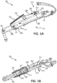
- FIGS. 1A and 1B show locking linkage system 200, which is part of a landing gear assembly, comprising a lockable assembly 211.
- Lockable assembly 211 may comprise an upper brace 202, a lower brace 204, and a linkage coupled between upper brace 202 and lower brace 204.
- locking linkage system 200 operates upper brace 202 relative to lower brace 204, such as by moving (e.g., rotating) lower brace 204 relative to upper brace 202.
- Locking linkage system 200 comprises coupling pins 221 which couple the various components of locking linkage system 200 together.
- Braces 202, 204 are coupled together via the linkage which comprises upper and lower lock links 206, 208, respectively.
- Lock springs 210 are coupled to upper brace 202 and upper lock link 206, although there are many other ways that lock springs 210 may be attached, and lock springs 210 may be attached to locking linkage system 200 at points other than upper brace 202 and upper lock link 206.
- Lock springs 210 may take the form of extension springs that provide a tensile force to pull upper lock link 206 into a locked position, but other types of springs may be used.
- locking linkage system 200 may comprise a downlock actuator 212, which is electrically powered, that may replace or be initially installed in lieu of a conventional hydraulic downlock actuator.
- Downlock actuator 212 may comprise an electric motor 214, a gearbox 216, a connecting output shaft 218 (coupled to, and extending from, electric motor 214 and/or gearbox 216), and a link rod 220, which may take the form of a fixed-length link rod.
- Downlock actuator 212 may take the form of an electric rotary mechanism with no linear motion output, but instead provides rotary output via a rotary output shaft 215, which drives connecting output shaft 218, connecting output shaft 218 being coupled to rotary output shaft 215.
- rotary output shaft 215 may be coupled to electric motor 214 and/or gearbox 216.
- Electric motor 214 and/or gearbox 216 may be rigidly coupled to upper brace 202.
- Electrical power cords are arranged to supply electrical power to electric motor 214.
- Downlock actuator 212 may be configured to toggle the linkage, upper brace 202, and lower brace 204 between an unlocked position and a locked position. As depicted in FIG. 1A , the linkage is positioned in locked link position 207.
- electric motor 214 may be positioned such that rotary output shaft 215 is substantially perpendicular to the linear direction of motion required.
- rotary output shaft 215 of electric motor 214 or gearbox 216 may be positioned substantially perpendicular to a longitudinal axis of link rod 220 and/or perpendicular to a plane of motion defined as a plane that is orthogonal to the axes of coupling pins 221.
- link rod 220 couples to connecting output shaft 218 at a location displaced from a centerline of rotation of gearbox 216, electric motor 214, or rotary output shaft 215.
- FIGS. 2A and 2B depict perspective views of a downlock actuator 212, in accordance with various embodiments. Elements with the like element numbering between figures are intended to be the same and will not be repeated for the sake of clarity.
- a first shaft end 219 of connecting output shaft 218 may be coupled to rotary output shaft 215 (depicted in FIG. IB) of electric motor 214 and/or gearbox 216.
- Rotary output shaft 215 may be fixedly coupled to electric motor 214 and/or gearbox 216.
- a second shaft end of connecting output shaft 218 may comprise a connection pin 239.
- connection pin 239 may be anywhere along connecting output shaft 218.
- a proximal end 222 of link rod 220 may comprise a lost-motion joint 230.
- lost-motion joint 230 may be comprised anywhere along link rod 220.
- Lost-motion joint 230 may comprise a joint void 232 defined by a void rim 231, through which connection pin 239 is disposed, coupling connecting output shaft 218 to link rod 220.
- a distal end 223 of link rod 220 may be coupled to the linkage, such as upper lock link 206.
- a lost motion joint comprised in a downlock actuator may be disposed in various locations.
- lost-motion joint 230 may be disposed at a coupling point between link rod 220 and connecting output shaft 218. As depicted in FIGS. 2A and 2B , the coupling point may be at proximal end 222 of link rod 220 and connection pin 239.
- a lost motion joint may be comprised on connecting output shaft, and link rod 220 may comprise the connection pin disposed in the lost motion joint.
- the lost-motion joint may be disposed at a link coupling point 229 between link rod 220 and upper lock link 206, comprised in link rod 220 or upper lock link 206.
- upper lock link 206 may comprise a connection pin disposed within the lost-motion joint.
- link rod 220 in which the lost-motion joint is comprised on upper lock link 206 at a link coupling point 229 between link rod 220 and upper lock link 206, link rod 220 may comprise a connection pin disposed within the lost-motion joint.
- the lost motion joint may be comprised on rotary output shaft 215.
- joint void 232 comprises a first end 233, a second end 234, and a void length 235 between the first end 233 and the second end 234.
- Connection pin 239 may have a pin thickness (for example, a pin diameter in the case in which connection pin 239 has a circular cross section).
- Void length 235 may be longer than the pin thickness of connection pin 239 such that connection pin 239 may translate within joint void 232 along void length 235.
- joint void 232 may be designed such that connection pin 239 may not contact first end 233 and second end 234 of joint void 232 simultaneously.
- connection pin 239 may only contact either first end 233 or second 234 at any given time, or connection pin 239 may be physically separated from both first end 233 and second end 234 at any given time.
- locking linkage system 200 and/or downlock actuator 212 may comprise a joint position sensor 243 configured to detect a position of connection pin 239 within joint void 232 along void length 235.
- link rod 220 operates to drive motion in the lock links 206, 208.
- Link rod 220 may be mounted for longitudinal translation, relative to the longitudinal axis 265 defined by upper brace 202, and rotation, relative to the connecting output shaft 218, whereby proximal end 222 of link rod 220 moves away from upper brace 202 and distal end 223 of link rod 220 moves toward upper brace 202 to unlock braces 202, 204 from the locked position to the unlocked position.
- Electric motor 214 may include motor control electronics that are programmable to control an angular position of connecting output shaft 218.
- the motor control electronics may be programmed using output position feedback detected by an output shaft position sensor 241 coupled to locking linkage system 200 proximate to connecting output shaft 218.
- a signal from output shaft position sensor 241 indicating that connecting output shaft 218 has reached a desired position may result in electric motor 214 being be shut off to maintain such a position, or electric motor 214 may be commanded to maintain such a position.
- connecting output shaft 218 may remain in the desired position by friction within electric motor 214 and/or gearbox 216 due to reflected inertia.
- electric motor 214 may be configured to receive the position of connecting output shaft 218 from output shaft position sensor 241 and to apply a compensatory torque in the event of movement of the connecting output shaft 218. Such control may be accomplished using a proportional-integral-derivative controller or a proportional-integral controller. In various embodiments, springs coupled to connecting output shaft 218 may be used to hold connecting output shaft 218 in a desired position.
- Gearbox 216 may provide a speed reduction between electric motor 214 and connecting output shaft 218 such that operation of electric motor 214 may produce a limited angular range of motion of connecting output shaft 218 between a fixed locked position 224 and a fixed unlocked position 226.
- the motor control electronics could also be used to provide precise control of a position of connecting output shaft 218 over a desired angular range, which may be the limited angular range between fixed locked position 224 and fixed unlocked position 226.
- Fixed locked position 224 is the position of connecting output shaft 218 which causes downlock actuator 212 to lock upper lock link 206 and lower lock link 208, and upper brace 202 and lower brace 204, such that braces 202, 204 are substantially along a longitudinal axis defined by upper brace 202, parallel to longitudinal axis 265, which results in the landing gear of an aircraft being fully extended.
- Upper lock link 206 and lower lock link 208 are in locked link position 207 (as depicted in FIGS. 1A and 2A ) in response to connecting output shaft 218 being in fixed locked position 224.
- Fixed locked position 224 is the closest position that connecting output shaft 218 may move about electric motor 214 and/or gearbox 216 toward upper brace 202, creating a minimum angle between upper brace 202 and connecting output shaft 218.
- Connection pin 239 will be against first end 233 of joint void 232 in response to connecting output shaft 218 being in fixed locked position 224.
- Fixed unlocked position 226 is the position of connecting output shaft 218 at which output shaft position sensor 241 detects that lock links 206, 208 are positively unlocked so upper brace 202 and lower brace 204 may move relative to one another to allow retraction of the landing gear, such as lower brace 204 moving in direction 253.
- Upper lock link 206 and lower lock link 208 are in unlocked link position 209 (as depicted in FIGS. 3A and 3B ), or moving toward unlocked link position 209, in response to connecting output shaft 218 being in fixed unlocked position 226.
- Fixed unlocked position 226 is the furthest position that connecting output shaft 218 may move about electric motor 214 and/or gearbox 216 away from upper brace 202, creating a maximum angle between upper brace 202 and connecting output shaft 218. Any position of connecting output shaft 218 between fixed locked position 224 and fixed unlocked position 226 may be referred to as an intermediate unlocked position. In an intermediate unlocked position, lock links 206, 208 may be in unlocked link position 209 or moving toward unlocked link position 209.
- locking linkage system 200 may comprise a link position sensor 245 disposed proximate to upper lock link 206 and/or lower lock link 208.
- Link position sensor 245 may be configured to detect the position of the lock links 206, 208, whether they are in locked link position 207 or unlocked link position 209, or somewhere between locked link position 207 and unlocked link position 209, i.e., an intermediate unlocked link position.
- FIG. 5 depicts a method 500 for unlocking locking linkage system 200 to allow retraction of the landing gear, in accordance with various embodiments.
- locking linkage system 200 may begin method 500 with connecting output shaft 218 in fixed locked position 224 and upper lock link 206 and lower lock link 208 being in locked link position 207.
- connection pin 239 may be in contact with first end 233 of joint void 232 of lost-motion joint 230, in a resting locked position 227.
- Electric motor 214 may be rotated (step 502) in response to being powered to rotate.
- rotary output shaft 215 may rotate (step 504), rotary output shaft 215 being coupled to electric motor 214 and/or gearbox 216.
- connecting output shaft 218 may rotate (step 506) from fixed locked position 224 away from upper brace 202 toward fixed unlocked position 226. Rotation by connecting output shaft 218 may cause connection pin 239 to translate within joint void 232 (step 508) from first end 233 to second end 234 of joint void 232.
- link rod 220 may not translate longitudinally, i.e., substantially parallel to longitudinal axis 265. That is, connecting output shaft 218 may rotate independently of link rod 220.
- connection pin 239 reaching second end 234 of joint void 232
- the rotation of connecting output shaft 218 may cause link rod 220 to translate in first longitudinal direction 266 (step 510).
- link rod 220 may cause upper lock link 206 and lower lock link 208 to move in first longitudinal direction 266, which may unlock locking linkage system 200.
- the output shaft position sensor 241 may detect that connecting output shaft 218 has reached fixed unlocked position 226 (step 512). In response, as described herein, electric motor 214 may be shut off so connecting output shaft 218 maintains fixed unlocked position 226 due to reflected inertia, and/or electric motor 214 may be commanded to actively maintain connecting output shaft 218 in fixed unlocked position 226.
- joint position sensor 243 may detect a position of connection pin 239 within joint void 232 (step 514) in response to connecting output shaft 218 reaching fixed unlocked position 226.
- Joint position sensor 243 may detect a floating position 228 of connection pin 239 within joint void 232, and/or cause connection pin 239 to be disposed in floating position 228.
- Floating position 228 may be a position of connection pin 239 within joint void 232 in which connection pin 239 is free from contact with first end 233 and second end 234 of joint void 232. That is, in floating position 228, connection pin 239 may be physically separated from both first end 233 and second end 234 of joint void 232.
- connection pin 239 may be in floating position 228 in response to connecting output shaft 218 being in fixed unlocked position 226 and/or lock links 206, 208 being in unlocked link position 209.
- link rod 220 is not needed to provide a continued force on lock links 206, 208, and a retract mechanism continues to fold locking linkage system 200 during a landing gear retraction (lower brace 204 moves in direction 253 relative to upper brace 202). From this point and through the rest of the motion that locking linkage system 200 articulates during retraction, link rod 220 and the other components of the downlock actuator 212 are positioned as to not hinder the retraction of the landing gear.
- lock links 206, 208 go through their defined motion, which is, in turn, realized as longitudinal motion substantially parallel to longitudinal axis 265 of link rod 220.
- Lost-motion joint 230 coupled to proximal end 222 of link rod 220 may allow link rod 220 to longitudinally move, in response to the defined motion of lock links 206, 208, without applying a load to connecting output shaft 218.
- lost-motion joint 230 may be designed such that joint void 232 allows longitudinal translation, in both first longitudinal direction 266 and second longitudinal direction 267, of link rod 220 in response to the defined motion of lock links 206, 208 during landing gear retraction without connection pin 239, which may be stationary in fixed unlocked position 226, contacting first end 233 or second end 234 of joint void 232. That way, connecting output shaft 218 will not be disturbed from fixed unlocked position 226.
- electric motor 214 and/or gearbox 216 may not comprise a clutch. Therefore, gearbox 216 may be fixedly coupled to electric motor 214 and connecting output shaft 218 may be fixedly coupled to rotary output shaft 215. Lock links 206, 208 may continue their motion until they reach unlocked link position 209, and link position sensor 245 may detect the same.
- FIG. 6 depicts a method 600 for locking locking linkage system 200, in response to landing gear extension, in accordance with various embodiments.
- locking linkage system 200 may begin method 600 with connecting output shaft 218 in fixed unlocked position 226, connection pin in floating position 228, and upper lock link 206 and lower lock link 208 being in unlocked link position 209.
- the landing gear extension process may begin with the retract actuator being powered to extend the landing gear.
- Lower brace 204 moves relative to upper brace 202 in a direction opposite direction 253, which may cause longitudinal translation of link rod 220 and lost-motion joint 230 relative to connection pin 239.
- Lost-motion joint 230 prevents such translation from applying a load to connecting output shaft 218.
- Link rod 220 may then translate in second longitudinal direction 267 (step 602).
- lost-motion joint 230 translates in second longitudinal direction 267 relative to connection pin 239, which is stationary in fixed unlocked position 226.
- joint position sensor 243 may detect the position of connection pin 239 within joint void 232 (step 604) as contacting second end 234 of joint void 232.
- electric motor 214 may rotate (step 608) by being powered to do so.
- a load from lost-motion joint 230 may be applied to connecting output shaft 218 in second longitudinal direction 267.
- connecting output shaft 218 may reach a triggering position, and that position of connecting output shaft 218 may be detected (step 606) by output shaft position sensor 241, and in response, electric motor 214 may rotate (step 608) by being powered to do so.
- the triggering position may be the same position or nearly the same position as fixed unlocked position 226.
- steps 604 and 606 may be performed in the alternative or in conjunction with one another.
- Rotary output shaft 215 may rotate (step 610) in response to the rotation of electric motor 214, causing connecting output shaft 218 to rotate (step 612) toward upper brace 202.
- connection pin 239 may translate along joint void 232, not yet applying a load to link rod 220.
- step 610 upper brace 202 and lower brace 204 may continue to extend, and thus link rod 220 may continue to translate in second longitudinal direction 267.
- Connection pin 239 of link rod 220 may reach first end 233 of joint void 232 from the rotation of connecting output shaft 218 and apply a load to link rod 220, as shown in FIG. 4 .
- the rotation of connecting output shaft 218 may continue to translate link rod 220 in second longitudinal direction 267 (step 614).
- Connecting output shaft 218 may continue applying a load on link rod 220 in second longitudinal direction 267 until connecting output shaft reaches fixed locked position 224.
- Output shaft position sensor 241 may detect that connecting output shaft 218 reached fixed locked position 224 (step 616), at which point, connection pin may be in resting locked position 227 against first end 233, and lock links 206, 208 may be in locked link position 207.
- Link position sensor 245 may detect the same.
- electric motor 214 may be shut off or commanded to maintain connecting output shaft 218 in fixed locked position 224.
- references to “one embodiment”, “an embodiment”, “various embodiments”, etc. indicate that the embodiment described may include a particular feature, structure, or characteristic, but every embodiment may not necessarily include the particular feature, structure, or characteristic. Moreover, such phrases are not necessarily referring to the same embodiment.
- the terms “comprises”, “comprising”, or any other variation thereof, are intended to cover a non-exclusive inclusion, such that a process, method, article, or apparatus that comprises a list of elements does not include only those elements but may include other elements not expressly listed or inherent to such process, method, article, or apparatus.
Landscapes
- Engineering & Computer Science (AREA)
- Mechanical Engineering (AREA)
- General Engineering & Computer Science (AREA)
- Aviation & Aerospace Engineering (AREA)
- Transmission Devices (AREA)
- Rehabilitation Tools (AREA)
- Manipulator (AREA)
Description
- This disclosure relates to an electrically powered downlock actuation system attachable to a landing gear brace, and more specifically to an electrically-powered downlock actuation system that uses the rotary output of an electric motor to directly drive a landing gear brace locking mechanism.
- Landing gear assemblies are configured to retract the landing gear of an aircraft after takeoff and deploy the landing gear before landing. Landing gear assemblies may include locking linkage systems, for example those comprising a downlock actuator, configured to actuate the locking and unlocking of the landing gear. When in an unlocked position, during landing gear retraction or extension, components within the downlock actuator may translate longitudinally in response to movement within the locking linkage system or landing gear assembly as a whole.
US 2006/163426 andUS 2011/163202 relate to locking mechanisms.EP 2 386 487 relates to an electrically-powered downlock actuation system. - According to an aspect of the invention, a locking linkage system of a landing gear assembly comprises a lockable assembly comprising an upper brace defining a longitudinal axis, a lower brace coupled to the upper brace, and a linkage coupled to the upper brace and the lower brace. The linkage is configured to allow movement of the upper brace and the lower brace relative to one another between unlocked and locked positions. The locking linkage system further comprises a downlock actuator comprising an electric motor coupled to the upper brace; a rotary output shaft coupled to the electric motor; a connecting output shaft having a first shaft end and a second shaft end, the first shaft end being coupled to the rotary output shaft, wherein the connecting output shaft is configured to rotate between a fixed locked position and a fixed unlocked position; and a link rod having a distal end coupled to the linkage and a proximal end comprising a lost-motion joint, the lost-motion joint being coupled to a connection pin of the second shaft end of the connecting output shaft, wherein the downlock actuator is configured to toggle the linkage, the upper brace, and the lower brace between an unlocked position and a locked position.
- In various embodiments, the lost-motion joint may comprise a joint void defined by a void rim, wherein the connection pin is disposed within the joint void, wherein the joint void has a void length that is longer than a pin thickness of the connection pin such that the connection pin may translate within the joint void and the connection pin may only contact one of a first end and a second end of the joint void at a time. In various embodiments, the connection pin may be in contact with the first end of the joint void in response to the connecting output shaft being in the fixed locked position. In various embodiments, connection pin may be in a floating position in the joint void in response to the connecting output shaft being in the fixed unlocked position, the floating position being a pin position in which the connection pin is physically separated from the first end and the second end of the joint void.
- In various embodiments, the linkage may comprise an upper lock link pivotally coupled to a lower lock link, wherein the upper lock link is coupled to the upper brace and the lower lock link is coupled to the lower brace. In various embodiments, the locking linkage system may further comprise an output shaft position sensor proximate the connecting output shaft, wherein the output shaft position sensor is configured to detect a shaft position of the connecting output shaft. In various embodiments, the locking linkage system may further comprise a joint position sensor, proximate the lost-motion joint, configured to detect a pin position of the connection pin along the void length. In various embodiments, the locking linkage system may further comprise a gearbox to provide a desired amount of speed change between the electric motor and the connecting output shaft, wherein the gearbox is fixedly coupled to the electric motor, the rotary output shaft is fixedly coupled to the gearbox, and the connecting output shaft is fixedly coupled to the rotary output shaft.
- In various embodiments, a downlock actuator for a landing gear system may comprise an electric motor; a rotary output shaft coupled to the electric motor; a connecting output shaft having a first shaft end and a second shaft end, the first shaft end being coupled to the rotary output shaft, wherein the connecting output shaft is configured to rotate between a fixed locked position and a fixed unlocked position; and a link rod having a proximal end comprising a lost-motion joint, the lost-motion joint being coupled to a connection pin of the second shaft end of the connecting output shaft.
- In various embodiments, the lost-motion joint may comprise a joint void defined by a void rim, wherein the joint void has a void length that is longer than a pin thickness of the connection pin such that the connection pin may translate within the joint void and the connection pin may only contact one of a first end and a second end of the joint void at a time. In various embodiments, the link rod further comprises a distal end coupled to a lockable assembly, which includes a linkage, an upper brace, and a lower brace, and wherein, the connecting output shaft and the link rod are configured to toggle the linkage, the upper brace, and the lower brace between an unlocked position and a locked position.
- In various embodiments, the downlock actuator may further comprise an output shaft position sensor proximate to the connecting output shaft configured to detect a shaft position of the connecting output shaft. In various embodiments, the downlock actuator may further comprise a joint position sensor, proximate the lost-motion joint, configured to detect a pin position of the connection pin along the void length.
- In various embodiments, the connection pin may be in contact with the first end of the joint void in response to the connecting output shaft being in the fixed locked position. In various embodiments, the connection pin may be in a floating position in the joint void in response to the connecting output shaft being in the fixed unlocked position, the floating position being a pin position in which the connection pin is physically separated from the first end and the second end of the joint void.
- According to a further aspect of the invention, a method of positioning an upper brace and a lower brace of an aircraft landing gear system in a desired relationship with one another comprises rotating an electric motor coupled to the upper brace in a desired rotational direction, rotating a rotary output shaft coupled to the electric motor, and rotating a connecting output shaft between a fixed locked position and a fixed unlocked position in response to the rotating the rotary output shaft, a first shaft end of the connecting output shaft being coupled to the rotary output shaft. Furthermore, rotating the connecting output shaft comprises translating a connection pin, coupled to the connecting output shaft, between a first end of a joint void in a lost-motion joint and a second end of the joint void, wherein the lost-motion joint is coupled to a proximal end of a link rod, the link rod having a distal end coupled to a linkage which is coupled to the upper brace and the lower brace, and wherein the connecting output shaft rotates independently of the link rod throughout the translating the connection pin between the first end and the second end of the joint void.
- In various embodiments, the method may further comprise translating the link rod in a first longitudinal direction in response to the connecting output shaft rotating toward the fixed unlocked position, wherein, in response to the connecting output shaft reaching the fixed unlocked position, the connection pin reaches a floating position in the joint void, the floating position being a pin position in which the connection pin is physically separated from the first end and the second end of the joint void. In various embodiments, the method may further comprise translating the link rod in a second longitudinal direction in response to the connecting output shaft rotating toward the fixed locked position. In various embodiments, the method may further comprise detecting a shaft position of the connecting output shaft with an output shaft position sensor located proximate the connecting output shaft. In various embodiments, rotating the connecting output shaft may comprise at least one of rotating the connecting output shaft from the fixed locked position, and stopping at the fixed unlocked position in response to the output shaft position sensor detecting the connecting output shaft arriving at the fixed unlocked position, or rotating the connecting output shaft from the fixed unlocked position, and stopping at the fixed locked position in response to the output shaft position sensor detecting the connecting output shaft arriving at the fixed locked position.
- The subject matter of the present disclosure is particularly pointed out and distinctly claimed in the concluding portion of the specification. A more complete understanding of the present disclosure, however, may best be obtained by referring to the detailed description and claims when considered in connection with the drawing figures. In the figures, like referenced numerals may refer to like parts throughout the different figures unless otherwise specified.
-
FIG. 1A illustrates a side view of a locking linkage system for a landing gear system, in accordance with various embodiments; -
FIG. 1B illustrates a top view of a locking linkage system for a landing gear system, in accordance with various embodiments; -
FIG. 2A illustrates a perspective view of a downlock actuator in a fixed locked position, in accordance with various embodiments; -
FIG. 2B illustrates a perspective view of a downlock actuator in an intermediate unlocked position, in accordance with various embodiments; -
FIG. 3A illustrates a side view of a locking linkage system for a landing gear system in a fixed unlocked position, in accordance with various embodiments; -
FIG. 3B illustrates a perspective view of a downlock actuator in a fixed unlocked position, in accordance with various embodiments; -
FIG. 4 illustrates a perspective view of a downlock actuator in another intermediate unlocked position; -
FIG. 5 illustrates a method for unlocking a locking linkage system to allow retraction of landing gear, in accordance with various embodiments; and -
FIG. 6 illustrates a method for locking a locking linkage system, in accordance with various embodiments. - All ranges may include the upper and lower values, and all ranges and ratio limits disclosed herein may be combined. It is to be understood that unless specifically stated otherwise, references to "a," "an," and/or "the" may include one or more than one and that reference to an item in the singular may also include the item in the plural.
- The detailed description of various embodiments herein makes reference to the accompanying drawings, which show various embodiments by way of illustration. While these various embodiments are described in sufficient detail to enable those skilled in the art to practice the disclosure, it should be understood that other embodiments may be realized and that logical, chemical, and mechanical changes may be made without departing from the scope of the disclosure. Thus, the detailed description herein is presented for purposes of illustration only and not of limitation. For example, the steps recited in any of the method or process descriptions may be executed in any order and are not necessarily limited to the order presented. Furthermore, any reference to singular includes plural embodiments, and any reference to more than one component or step may include a singular embodiment or step. Also, any reference to attached, fixed, connected, or the like may include permanent, removable, temporary, partial, full, and/or any other possible attachment option. Additionally, any reference to without contact (or similar phrases) may also include reduced contact or minimal contact.
- This disclosure generally relates to an electrically powered downlock actuation system, or downlock actuator, for landing gear braces, such as the braces in a locking linkage system making up a landing gear drag brace or side brace. Electrically actuated downlock actuators present a different set of challenges relative to hydraulically powered downlock actuators. For example, the electrical actuation components should fit substantially within the same space constraints or spatial envelope, not substantially increase the weight of the overall downlock actuation system, and minimize force inefficiencies in the overall landing gear design. Generally, electrically powered linear actuators may lose efficiency in converting rotary motor output into linear motion. In various embodiments, a locking linkage system includes a downlock actuator, which may be electrically-powered, for a landing gear system that does not convert rotary motor output into linear motion during the actuation process, but instead uses the rotary motor output to directly drive a locking mechanism coupled to a landing gear brace. The locking linkage system substantially fits within the same space constraints as hydraulically powered downlock actuators and achieves adequate reliability and maintainability ratings.
-
FIGS. 1A and 1B show lockinglinkage system 200, which is part of a landing gear assembly, comprising alockable assembly 211.Lockable assembly 211 may comprise anupper brace 202, alower brace 204, and a linkage coupled betweenupper brace 202 andlower brace 204. In various embodiments, lockinglinkage system 200 operatesupper brace 202 relative to lowerbrace 204, such as by moving (e.g., rotating)lower brace 204 relative toupper brace 202. Lockinglinkage system 200 comprises coupling pins 221 which couple the various components of lockinglinkage system 200 together.Braces lower lock links Upper lock link 206 is pivotally coupled tolower lock link 208. Lock springs 210 are coupled toupper brace 202 andupper lock link 206, although there are many other ways that lock springs 210 may be attached, and lock springs 210 may be attached to lockinglinkage system 200 at points other thanupper brace 202 andupper lock link 206. Lock springs 210 may take the form of extension springs that provide a tensile force to pull upper lock link 206 into a locked position, but other types of springs may be used. - In various embodiments, locking
linkage system 200 may comprise adownlock actuator 212, which is electrically powered, that may replace or be initially installed in lieu of a conventional hydraulic downlock actuator.Downlock actuator 212 may comprise anelectric motor 214, agearbox 216, a connecting output shaft 218 (coupled to, and extending from,electric motor 214 and/or gearbox 216), and alink rod 220, which may take the form of a fixed-length link rod.Downlock actuator 212 may take the form of an electric rotary mechanism with no linear motion output, but instead provides rotary output via arotary output shaft 215, which drives connectingoutput shaft 218, connectingoutput shaft 218 being coupled torotary output shaft 215. In various embodiments,rotary output shaft 215 may be coupled toelectric motor 214 and/orgearbox 216.Electric motor 214 and/orgearbox 216 may be rigidly coupled toupper brace 202. Electrical power cords are arranged to supply electrical power toelectric motor 214.Downlock actuator 212 may be configured to toggle the linkage,upper brace 202, andlower brace 204 between an unlocked position and a locked position. As depicted inFIG. 1A , the linkage is positioned in lockedlink position 207. - In various embodiments,
electric motor 214 may be positioned such thatrotary output shaft 215 is substantially perpendicular to the linear direction of motion required. Stated another way,rotary output shaft 215 ofelectric motor 214 orgearbox 216 may be positioned substantially perpendicular to a longitudinal axis oflink rod 220 and/or perpendicular to a plane of motion defined as a plane that is orthogonal to the axes of coupling pins 221. In turn,link rod 220 couples to connectingoutput shaft 218 at a location displaced from a centerline of rotation ofgearbox 216,electric motor 214, orrotary output shaft 215. -
FIGS. 2A and 2B depict perspective views of adownlock actuator 212, in accordance with various embodiments. Elements with the like element numbering between figures are intended to be the same and will not be repeated for the sake of clarity. In various embodiments, afirst shaft end 219 of connectingoutput shaft 218 may be coupled to rotary output shaft 215 (depicted in FIG. IB) ofelectric motor 214 and/orgearbox 216.Rotary output shaft 215 may be fixedly coupled toelectric motor 214 and/orgearbox 216. A second shaft end of connectingoutput shaft 218 may comprise aconnection pin 239. In various embodiments,connection pin 239 may be anywhere along connectingoutput shaft 218. Aproximal end 222 oflink rod 220 may comprise a lost-motion joint 230. In various embodiments, lost-motion joint 230 may be comprised anywhere alonglink rod 220. Lost-motion joint 230 may comprise ajoint void 232 defined by avoid rim 231, through whichconnection pin 239 is disposed, coupling connectingoutput shaft 218 to linkrod 220. Adistal end 223 oflink rod 220 may be coupled to the linkage, such asupper lock link 206. - In various embodiments, a lost motion joint comprised in a downlock actuator may be disposed in various locations. In various embodiments, lost-motion joint 230 may be disposed at a coupling point between
link rod 220 and connectingoutput shaft 218. As depicted inFIGS. 2A and 2B , the coupling point may be atproximal end 222 oflink rod 220 andconnection pin 239. In various embodiments, a lost motion joint may be comprised on connecting output shaft, andlink rod 220 may comprise the connection pin disposed in the lost motion joint. In various embodiments, the lost-motion joint may be disposed at alink coupling point 229 betweenlink rod 220 andupper lock link 206, comprised inlink rod 220 orupper lock link 206. In various embodiments, in which the lost-motion joint is comprised onlink rod 220 at alink coupling point 229 betweenlink rod 220 andupper lock link 206,upper lock link 206 may comprise a connection pin disposed within the lost-motion joint. In various embodiments, in which the lost-motion joint is comprised on upper lock link 206 at alink coupling point 229 betweenlink rod 220 andupper lock link 206,link rod 220 may comprise a connection pin disposed within the lost-motion joint. In various embodiments, the lost motion joint may be comprised onrotary output shaft 215. - With reference to
FIG. 2A, 2B ,3A, 3B , and4 in various embodiments,joint void 232 comprises afirst end 233, asecond end 234, and avoid length 235 between thefirst end 233 and thesecond end 234.Connection pin 239 may have a pin thickness (for example, a pin diameter in the case in whichconnection pin 239 has a circular cross section).Void length 235 may be longer than the pin thickness ofconnection pin 239 such thatconnection pin 239 may translate withinjoint void 232 alongvoid length 235. In various embodiments,joint void 232 may be designed such thatconnection pin 239 may not contactfirst end 233 andsecond end 234 ofjoint void 232 simultaneously. Stated another way,connection pin 239 may only contact eitherfirst end 233 or second 234 at any given time, orconnection pin 239 may be physically separated from bothfirst end 233 andsecond end 234 at any given time. In various embodiments, lockinglinkage system 200 and/ordownlock actuator 212 may comprise ajoint position sensor 243 configured to detect a position ofconnection pin 239 withinjoint void 232 alongvoid length 235. - In various embodiments,
link rod 220 operates to drive motion in the lock links 206, 208.Link rod 220 may be mounted for longitudinal translation, relative to thelongitudinal axis 265 defined byupper brace 202, and rotation, relative to the connectingoutput shaft 218, wherebyproximal end 222 oflink rod 220 moves away fromupper brace 202 anddistal end 223 oflink rod 220 moves towardupper brace 202 to unlockbraces Electric motor 214 may include motor control electronics that are programmable to control an angular position of connectingoutput shaft 218. In various embodiments, the motor control electronics may be programmed using output position feedback detected by an outputshaft position sensor 241 coupled to lockinglinkage system 200 proximate to connectingoutput shaft 218. In various embodiments, a signal from outputshaft position sensor 241 indicating that connectingoutput shaft 218 has reached a desired position may result inelectric motor 214 being be shut off to maintain such a position, orelectric motor 214 may be commanded to maintain such a position. In response to electric motor being shut off, connectingoutput shaft 218 may remain in the desired position by friction withinelectric motor 214 and/orgearbox 216 due to reflected inertia. In various embodiments,electric motor 214 may be configured to receive the position of connectingoutput shaft 218 from outputshaft position sensor 241 and to apply a compensatory torque in the event of movement of the connectingoutput shaft 218. Such control may be accomplished using a proportional-integral-derivative controller or a proportional-integral controller. In various embodiments, springs coupled to connectingoutput shaft 218 may be used to hold connectingoutput shaft 218 in a desired position. -
Gearbox 216 may provide a speed reduction betweenelectric motor 214 and connectingoutput shaft 218 such that operation ofelectric motor 214 may produce a limited angular range of motion of connectingoutput shaft 218 between a fixed lockedposition 224 and a fixedunlocked position 226. The motor control electronics could also be used to provide precise control of a position of connectingoutput shaft 218 over a desired angular range, which may be the limited angular range between fixed lockedposition 224 and fixedunlocked position 226. - Fixed locked
position 224 is the position of connectingoutput shaft 218 which causesdownlock actuator 212 to lockupper lock link 206 andlower lock link 208, andupper brace 202 andlower brace 204, such that braces 202, 204 are substantially along a longitudinal axis defined byupper brace 202, parallel tolongitudinal axis 265, which results in the landing gear of an aircraft being fully extended.Upper lock link 206 andlower lock link 208 are in locked link position 207 (as depicted inFIGS. 1A and2A ) in response to connectingoutput shaft 218 being in fixed lockedposition 224. Fixed lockedposition 224 is the closest position that connectingoutput shaft 218 may move aboutelectric motor 214 and/orgearbox 216 towardupper brace 202, creating a minimum angle betweenupper brace 202 and connectingoutput shaft 218.Connection pin 239 will be againstfirst end 233 ofjoint void 232 in response to connectingoutput shaft 218 being in fixed lockedposition 224. - Fixed
unlocked position 226 is the position of connectingoutput shaft 218 at which outputshaft position sensor 241 detects that lock links 206, 208 are positively unlocked soupper brace 202 andlower brace 204 may move relative to one another to allow retraction of the landing gear, such aslower brace 204 moving indirection 253.Upper lock link 206 andlower lock link 208 are in unlocked link position 209 (as depicted inFIGS. 3A and 3B ), or moving towardunlocked link position 209, in response to connectingoutput shaft 218 being in fixedunlocked position 226. Fixedunlocked position 226 is the furthest position that connectingoutput shaft 218 may move aboutelectric motor 214 and/orgearbox 216 away fromupper brace 202, creating a maximum angle betweenupper brace 202 and connectingoutput shaft 218. Any position of connectingoutput shaft 218 between fixed lockedposition 224 and fixedunlocked position 226 may be referred to as an intermediate unlocked position. In an intermediate unlocked position, locklinks unlocked link position 209 or moving towardunlocked link position 209. - In various embodiments, locking
linkage system 200 may comprise alink position sensor 245 disposed proximate toupper lock link 206 and/orlower lock link 208.Link position sensor 245 may be configured to detect the position of the lock links 206, 208, whether they are in lockedlink position 207 orunlocked link position 209, or somewhere between lockedlink position 207 andunlocked link position 209, i.e., an intermediate unlocked link position. -
FIG. 5 depicts amethod 500 for unlockinglocking linkage system 200 to allow retraction of the landing gear, in accordance with various embodiments. With combined reference toFIGS. 2A, 2B ,3A, 3B , and5 , in operation, lockinglinkage system 200 may beginmethod 500 with connectingoutput shaft 218 in fixed lockedposition 224 andupper lock link 206 andlower lock link 208 being in lockedlink position 207. In response to connectingoutput shaft 218 being in fixed lockedposition 224,connection pin 239 may be in contact withfirst end 233 ofjoint void 232 of lost-motion joint 230, in a resting lockedposition 227.Electric motor 214 may be rotated (step 502) in response to being powered to rotate. In response toelectric motor 214 rotating,rotary output shaft 215 may rotate (step 504),rotary output shaft 215 being coupled toelectric motor 214 and/orgearbox 216. In response, connectingoutput shaft 218 may rotate (step 506) from fixed lockedposition 224 away fromupper brace 202 toward fixedunlocked position 226. Rotation by connectingoutput shaft 218 may causeconnection pin 239 to translate within joint void 232 (step 508) fromfirst end 233 tosecond end 234 ofjoint void 232. During the translation ofconnection pin 239 fromfirst end 233 tosecond end 234 ofjoint void 232,link rod 220 may not translate longitudinally, i.e., substantially parallel tolongitudinal axis 265. That is, connectingoutput shaft 218 may rotate independently oflink rod 220. In response toconnection pin 239 reachingsecond end 234 ofjoint void 232, the rotation of connectingoutput shaft 218 may causelink rod 220 to translate in first longitudinal direction 266 (step 510). In response,link rod 220 may causeupper lock link 206 andlower lock link 208 to move in firstlongitudinal direction 266, which may unlock lockinglinkage system 200. - In various embodiments, subsequent to unlocking
locking linkage system 200, the outputshaft position sensor 241 may detect that connectingoutput shaft 218 has reached fixed unlocked position 226 (step 512). In response, as described herein,electric motor 214 may be shut off so connectingoutput shaft 218 maintains fixedunlocked position 226 due to reflected inertia, and/orelectric motor 214 may be commanded to actively maintain connectingoutput shaft 218 in fixedunlocked position 226. In various embodiments,joint position sensor 243 may detect a position ofconnection pin 239 within joint void 232 (step 514) in response to connectingoutput shaft 218 reaching fixedunlocked position 226.Joint position sensor 243 may detect a floatingposition 228 ofconnection pin 239 withinjoint void 232, and/or causeconnection pin 239 to be disposed in floatingposition 228. Floatingposition 228 may be a position ofconnection pin 239 withinjoint void 232 in whichconnection pin 239 is free from contact withfirst end 233 andsecond end 234 ofjoint void 232. That is, in floatingposition 228,connection pin 239 may be physically separated from bothfirst end 233 andsecond end 234 ofjoint void 232. In various embodiments,connection pin 239 may be in floatingposition 228 in response to connectingoutput shaft 218 being in fixedunlocked position 226 and/or locklinks unlocked link position 209. - In various embodiments, once locking
linkage system 200 has been positively unlocked, i.e., connecting output shaft is in an intermediate unlocked position or fixedunlocked position 226,link rod 220 is not needed to provide a continued force onlock links linkage system 200 during a landing gear retraction (lower brace 204 moves indirection 253 relative to upper brace 202). From this point and through the rest of the motion that lockinglinkage system 200 articulates during retraction,link rod 220 and the other components of thedownlock actuator 212 are positioned as to not hinder the retraction of the landing gear. To this end, during such landing gear retraction, with connectingoutput shaft 218 in fixedunlocked position 226 andconnection pin 239 in floatingposition 228, lock links 206, 208 go through their defined motion, which is, in turn, realized as longitudinal motion substantially parallel tolongitudinal axis 265 oflink rod 220. Lost-motion joint 230 coupled toproximal end 222 oflink rod 220 may allowlink rod 220 to longitudinally move, in response to the defined motion oflock links output shaft 218. Therefore, lost-motion joint 230 may be designed such thatjoint void 232 allows longitudinal translation, in both firstlongitudinal direction 266 and secondlongitudinal direction 267, oflink rod 220 in response to the defined motion oflock links connection pin 239, which may be stationary in fixedunlocked position 226, contactingfirst end 233 orsecond end 234 ofjoint void 232. That way, connectingoutput shaft 218 will not be disturbed from fixedunlocked position 226. For this reason, in various embodiments,electric motor 214 and/orgearbox 216 may not comprise a clutch. Therefore,gearbox 216 may be fixedly coupled toelectric motor 214 and connectingoutput shaft 218 may be fixedly coupled torotary output shaft 215. Lock links 206, 208 may continue their motion until they reachunlocked link position 209, andlink position sensor 245 may detect the same. -
FIG. 6 depicts amethod 600 for lockinglocking linkage system 200, in response to landing gear extension, in accordance with various embodiments. With combined reference toFIGS. 2A, 2B ,3A, 3B ,4 , and6 , in operation, lockinglinkage system 200 may beginmethod 600 with connectingoutput shaft 218 in fixedunlocked position 226, connection pin in floatingposition 228, andupper lock link 206 andlower lock link 208 being inunlocked link position 209. In various embodiments, the landing gear extension process may begin with the retract actuator being powered to extend the landing gear.Lower brace 204 moves relative toupper brace 202 in a directionopposite direction 253, which may cause longitudinal translation oflink rod 220 and lost-motion joint 230 relative toconnection pin 239. Lost-motion joint 230 prevents such translation from applying a load to connectingoutput shaft 218.Link rod 220 may then translate in second longitudinal direction 267 (step 602). In response, lost-motion joint 230 translates in secondlongitudinal direction 267 relative toconnection pin 239, which is stationary in fixedunlocked position 226. - In various embodiments, in response to
connection pin 239 nearly reaching, or reaching,second end 234 of joint void 232 (the position ofconnection pin 239 injoint void 232 inFIG. 2B resembles such a position),joint position sensor 243 may detect the position ofconnection pin 239 within joint void 232 (step 604) as contactingsecond end 234 ofjoint void 232. In response,electric motor 214 may rotate (step 608) by being powered to do so. In various embodiments, in response toconnection pin 239 reachingsecond end 234 ofjoint void 232, a load from lost-motion joint 230 may be applied to connectingoutput shaft 218 in secondlongitudinal direction 267. In response, connectingoutput shaft 218 may reach a triggering position, and that position of connectingoutput shaft 218 may be detected (step 606) by outputshaft position sensor 241, and in response,electric motor 214 may rotate (step 608) by being powered to do so. The triggering position may be the same position or nearly the same position as fixedunlocked position 226. In various embodiments,steps Rotary output shaft 215 may rotate (step 610) in response to the rotation ofelectric motor 214, causing connectingoutput shaft 218 to rotate (step 612) towardupper brace 202. In response,connection pin 239 may translate alongjoint void 232, not yet applying a load to linkrod 220. Duringstep 610,upper brace 202 andlower brace 204 may continue to extend, and thus linkrod 220 may continue to translate in secondlongitudinal direction 267.Connection pin 239 oflink rod 220 may reachfirst end 233 ofjoint void 232 from the rotation of connectingoutput shaft 218 and apply a load to linkrod 220, as shown inFIG. 4 . In response, the rotation of connectingoutput shaft 218 may continue to translatelink rod 220 in second longitudinal direction 267 (step 614).Connecting output shaft 218 may continue applying a load onlink rod 220 in secondlongitudinal direction 267 until connecting output shaft reaches fixed lockedposition 224. Outputshaft position sensor 241 may detect that connectingoutput shaft 218 reached fixed locked position 224 (step 616), at which point, connection pin may be in resting lockedposition 227 againstfirst end 233, and locklinks link position 207.Link position sensor 245 may detect the same. In response,electric motor 214 may be shut off or commanded to maintain connectingoutput shaft 218 in fixed lockedposition 224. - Benefits, other advantages, and solutions to problems have been described herein with regard to specific embodiments. Furthermore, the connecting lines shown in the various figures contained herein are intended to represent exemplary functional relationships and/or physical couplings between the various elements. It should be noted that many alternative or additional functional relationships or physical connections may be present in a practical system. However, the benefits, advantages, solutions to problems, and any elements that may cause any benefit, advantage, or solution to occur or become more pronounced are not to be construed as critical, required, or essential features or elements of the disclosure. The scope of the disclosure is accordingly to be limited by nothing other than the appended claims, in which reference to an element in the singular is not intended to mean "one and only one" unless explicitly so stated, but rather "one or more." Moreover, where a phrase similar to "at least one of A, B, or C" is used in the claims, it is intended that the phrase be interpreted to mean that A alone may be present in an embodiment, B alone may be present in an embodiment, C alone may be present in an embodiment, or that any combination of the elements A, B and C may be present in a single embodiment; for example, A and B, A and C, B and C, or A and B and C. Different cross-hatching is used throughout the figures to denote different parts but not necessarily to denote the same or different materials.
- Systems, methods and apparatus are provided herein. In the detailed description herein, references to "one embodiment", "an embodiment", "various embodiments", etc., indicate that the embodiment described may include a particular feature, structure, or characteristic, but every embodiment may not necessarily include the particular feature, structure, or characteristic. Moreover, such phrases are not necessarily referring to the same embodiment.
- As used herein, the terms "comprises", "comprising", or any other variation thereof, are intended to cover a non-exclusive inclusion, such that a process, method, article, or apparatus that comprises a list of elements does not include only those elements but may include other elements not expressly listed or inherent to such process, method, article, or apparatus.
Claims (10)
- A locking linkage system (200) of a landing gear system, the locking linkage system comprising:a lockable assembly (211) comprising:an upper brace (202) defining a longitudinal axis;a lower brace (204) coupled to the upper brace (202); anda linkage coupled to the upper brace (202) and the lower brace (204), the linkage being configured to allow movement of the upper brace (202) and the lower brace (204) relative to one another between unlocked and locked positions; anda downlock actuator (212) comprising:an electric motor (214) coupled to the upper brace (202);a rotary output shaft (215) coupled to the electric motor (214);a connecting output shaft (218) having a first shaft end and a second shaft end, the first shaft end being coupled to the rotary output shaft (215), wherein the connecting output shaft (218) is configured to rotate between a fixed locked position and a fixed unlocked position; anda link rod (220) having a distal end coupled to the linkage and a proximal end,wherein the downlock actuator (212) is configured to toggle the linkage, the upper brace (202), and the lower brace (204) between an unlocked position and a locked position,characterised in that the proximal end comprises a lost-motion joint, the lost-motion joint being coupled to a connection pin of the second shaft end of the connecting output shaft.
- The locking linkage system of claim 1, wherein the lost-motion joint comprises a joint void (232) defined by a void rim, wherein the connection pin (239) is disposed within the joint void, wherein the joint void has a void length that is longer than a pin thickness of the connection pin (239) such that the connection pin may translate within the joint void and the connection pin may only contact one of a first end (233) and a second end (2343) of the joint void at a time.
- The locking linkage system of claim 2, wherein the connection pin (239) is in contact with the first end (233) of the joint void in response to the connecting output shaft being in the fixed locked position; or wherein the connection pin (239) is in a floating position in the joint void in response to the connecting output shaft being in the fixed unlocked position, the floating position being a pin position in which the connection pin (239) is physically separated from the first end (233) and the second end (234) of the joint void; or further comprising a joint position sensor, proximate the lost-motion joint, configured to detect a pin position of the connection pin along the void length.
- The locking linkage system of claim 1, wherein the linkage comprises an upper lock link pivotally coupled to a lower lock link, wherein the upper lock link is coupled to the upper brace and the lower lock link is coupled to the lower brace.
- The locking linkage system of claim 1, further comprising an output shaft position sensor proximate the connecting output shaft, wherein the output shaft position sensor is configured to detect a shaft position of the connecting output shaft.
- The locking linkage system of claim 1, further comprising a gearbox (216) to provide a desired amount of speed change between the electric motor and the connecting output shaft, wherein the gearbox is fixedly coupled to the electric motor, the rotary output shaft is fixedly coupled to the gearbox, and the connecting output shaft is fixedly coupled to the rotary output shaft.
- A method (600) of positioning an upper brace and a lower brace of an aircraft landing gear system in a desired relationship with one another, comprising:rotating an electric motor in a desired rotational direction, the electric motor being coupled to the upper brace;rotating a rotary output shaft coupled to the electric motor; androtating a connecting output shaft between a fixed locked position and a fixed unlocked position in response to the rotating the rotary output shaft, a first shaft end of the connecting output shaft being coupled to the rotary output shaft, wherein the rotating the connecting output shaft comprises:
translating a connection pin, coupled to the connecting output shaft, between a first end of a joint void in a lost-motion joint and a second end of the joint void, wherein the lost-motion joint is coupled to a proximal end of a link rod, the link rod having a distal end coupled to a linkage which is coupled to the upper brace and the lower brace, and wherein the connecting output shaft rotates independently of the link rod throughout the translating the connection pin between the first end and the second end of the joint void. - The method of claim 7, further comprising translating the link rod in a first longitudinal direction in response to the connecting output shaft rotating toward the fixed unlocked position, wherein, in response to the connecting output shaft reaching the fixed unlocked position, the connection pin reaches a floating position in the joint void, the floating position being a pin position in which the connection pin is physically separated from the first end and the second end of the joint void.
- The method of claim 7, further comprising translating the link rod in a second longitudinal direction in response to the connecting output shaft rotating toward the fixed locked position.
- The method of claim 7, further comprising detecting a shaft position of the connecting output shaft with an output shaft position sensor located proximate the connecting output shaft, and preferably wherein the rotating the connecting output shaft comprises at least one of rotating the connecting output shaft from the fixed locked position, and stopping at the fixed unlocked position in response to the output shaft position sensor detecting the connecting output shaft arriving at the fixed unlocked position, or rotating the connecting output shaft from the fixed unlocked position, and stopping at the fixed locked position in response to the output shaft position sensor detecting the connecting output shaft arriving at the fixed locked position.
Applications Claiming Priority (1)
| Application Number | Priority Date | Filing Date | Title |
|---|---|---|---|
| US15/224,161 US10351227B2 (en) | 2016-07-29 | 2016-07-29 | Electrically powered downlock actuation system |
Publications (2)
| Publication Number | Publication Date |
|---|---|
| EP3275782A1 EP3275782A1 (en) | 2018-01-31 |
| EP3275782B1 true EP3275782B1 (en) | 2020-07-08 |
Family
ID=59070482
Family Applications (1)
| Application Number | Title | Priority Date | Filing Date |
|---|---|---|---|
| EP17175842.8A Active EP3275782B1 (en) | 2016-07-29 | 2017-06-13 | Electrically powered downlock actuation system |
Country Status (2)
| Country | Link |
|---|---|
| US (1) | US10351227B2 (en) |
| EP (1) | EP3275782B1 (en) |
Families Citing this family (3)
| Publication number | Priority date | Publication date | Assignee | Title |
|---|---|---|---|---|
| CN109305335A (en) * | 2018-11-05 | 2019-02-05 | 深圳市金鑫城纸品有限公司 | One kind being based on the retractable unmanned plane of mechanically operated undercarriage |
| US11230370B2 (en) * | 2019-01-23 | 2022-01-25 | Goodrich Corporation | Upper side stay with monolithic unlock actuator |
| US11638397B2 (en) * | 2020-02-10 | 2023-05-02 | Techtronic Cordless Gp | Control assembly coupled to handle of an implement |
Family Cites Families (16)
| Publication number | Priority date | Publication date | Assignee | Title |
|---|---|---|---|---|
| US1903039A (en) * | 1929-06-07 | 1933-03-28 | Gianoli Marcel Louis | Device for interlocking two movements |
| US2507962A (en) | 1948-08-18 | 1950-05-16 | United Aircraft Corp | Down lock for landing gears |
| US2668030A (en) | 1948-12-15 | 1954-02-02 | Curtiss Wright Corp | Aircraft landing gear lock |
| US2896884A (en) | 1954-07-06 | 1959-07-28 | Electro Hydraulics Ltd | Retractable aircraft landing gear |
| FR2686854B1 (en) | 1992-02-03 | 1994-04-01 | Messier Bugatti | LIFTABLE LANDING GEAR EQUIPPED WITH A DOUBLE-ALIGNED ARTICULATED PLUG. |
| GB0315941D0 (en) | 2003-07-08 | 2003-08-13 | Smiths Group Plc | Locking mechanisms |
| FR2928623B1 (en) | 2008-03-14 | 2010-03-12 | Messier Dowty Sa | UNLOCKING AN AIRCRAFT AIRCRAFT BREAKER STABILIZATION BODY |
| US8123161B1 (en) | 2008-06-03 | 2012-02-28 | Hamilton Sundstrand Corporation | Aircraft landing gear unlock actuator |
| FR2946319B1 (en) | 2009-06-05 | 2012-11-30 | Messier Dowty Sa | METHOD FOR MANEUVERING A BREAKER COUNTERFRAME |
| US8448900B2 (en) | 2010-03-24 | 2013-05-28 | The Boeing Company | Semi-levered landing gear and associated method |
| US8590835B2 (en) * | 2010-05-11 | 2013-11-26 | Goodrich Corporation | Electrically powered downlock actuation system |
| FR2960215B1 (en) | 2010-05-18 | 2012-06-08 | Messier Dowty Sa | DEVICE FOR UNLOCKING A LICENSOR IN A DEPLOYED POSITION AND LIGHTER EQUIPPED WITH SUCH A DEVICE |
| GB2489058B (en) | 2011-08-22 | 2013-05-08 | Messier Dowty Ltd | Aircraft landing gear |
| GB2501906A (en) | 2012-05-10 | 2013-11-13 | Ge Aviat Systems Ltd | Aircraft landing gear |
| GB2507823B (en) | 2012-11-27 | 2014-10-08 | Messier Dowty Ltd | Landing gear assembly with lost motion mechanism |
| GB2518605B (en) | 2013-09-18 | 2020-02-12 | Airbus Operations Ltd | Drive system for landing gear |
-
2016
- 2016-07-29 US US15/224,161 patent/US10351227B2/en active Active
-
2017
- 2017-06-13 EP EP17175842.8A patent/EP3275782B1/en active Active
Non-Patent Citations (1)
| Title |
|---|
| None * |
Also Published As
| Publication number | Publication date |
|---|---|
| EP3275782A1 (en) | 2018-01-31 |
| US20180029698A1 (en) | 2018-02-01 |
| US10351227B2 (en) | 2019-07-16 |
Similar Documents
| Publication | Publication Date | Title |
|---|---|---|
| EP2386487B1 (en) | Electrically powered downlock actuation system | |
| EP3744632B1 (en) | Electrically powered downlock actuation system | |
| EP3275782B1 (en) | Electrically powered downlock actuation system | |
| EP2130765B1 (en) | Aircraft landing gear unlock actuator | |
| EP2604514B1 (en) | Automatically locking linear actuator | |
| EP2107273B1 (en) | Actuator | |
| EP2041453B1 (en) | Flap actuator | |
| US10753444B2 (en) | Summing and fault tolerant rotary actuator assembly | |
| US20170045129A1 (en) | Drive assembly with selective disconnect | |
| US20130299633A1 (en) | Landing gear for an aircraft | |
| CN110366650B (en) | Cylinder with integrated locking | |
| WO2010009289A2 (en) | Aircraft landing gear actuator | |
| US11498658B2 (en) | System for an aircraft wing | |
| US11560218B2 (en) | Electromechanical actuator disconnect | |
| AU2006203480B9 (en) | A method and a system for setting into coincidence, a technique, a drive, and an aircraft | |
| EP3444184B1 (en) | Electric actuator with bidirectional compliance |
Legal Events
| Date | Code | Title | Description |
|---|---|---|---|
| PUAI | Public reference made under article 153(3) epc to a published international application that has entered the european phase |
Free format text: ORIGINAL CODE: 0009012 |
|
| STAA | Information on the status of an ep patent application or granted ep patent |
Free format text: STATUS: THE APPLICATION HAS BEEN PUBLISHED |
|
| AK | Designated contracting states |
Kind code of ref document: A1 Designated state(s): AL AT BE BG CH CY CZ DE DK EE ES FI FR GB GR HR HU IE IS IT LI LT LU LV MC MK MT NL NO PL PT RO RS SE SI SK SM TR |
|
| AX | Request for extension of the european patent |
Extension state: BA ME |
|
| STAA | Information on the status of an ep patent application or granted ep patent |
Free format text: STATUS: REQUEST FOR EXAMINATION WAS MADE |
|
| 17P | Request for examination filed |
Effective date: 20180731 |
|
| RBV | Designated contracting states (corrected) |
Designated state(s): AL AT BE BG CH CY CZ DE DK EE ES FI FR GB GR HR HU IE IS IT LI LT LU LV MC MK MT NL NO PL PT RO RS SE SI SK SM TR |
|
| GRAP | Despatch of communication of intention to grant a patent |
Free format text: ORIGINAL CODE: EPIDOSNIGR1 |
|
| STAA | Information on the status of an ep patent application or granted ep patent |
Free format text: STATUS: GRANT OF PATENT IS INTENDED |
|
| INTG | Intention to grant announced |
Effective date: 20200217 |
|
| GRAS | Grant fee paid |
Free format text: ORIGINAL CODE: EPIDOSNIGR3 |
|
| GRAA | (expected) grant |
Free format text: ORIGINAL CODE: 0009210 |
|
| STAA | Information on the status of an ep patent application or granted ep patent |
Free format text: STATUS: THE PATENT HAS BEEN GRANTED |
|
| AK | Designated contracting states |
Kind code of ref document: B1 Designated state(s): AL AT BE BG CH CY CZ DE DK EE ES FI FR GB GR HR HU IE IS IT LI LT LU LV MC MK MT NL NO PL PT RO RS SE SI SK SM TR |
|
| RIN1 | Information on inventor provided before grant (corrected) |
Inventor name: DITZLER, ADAM J. |
|
| REG | Reference to a national code |
Ref country code: CH Ref legal event code: EP Ref country code: AT Ref legal event code: REF Ref document number: 1288192 Country of ref document: AT Kind code of ref document: T Effective date: 20200715 |
|
| REG | Reference to a national code |
Ref country code: DE Ref legal event code: R096 Ref document number: 602017019257 Country of ref document: DE |
|
| REG | Reference to a national code |
Ref country code: IE Ref legal event code: FG4D |
|
| REG | Reference to a national code |
Ref country code: LT Ref legal event code: MG4D |
|
| REG | Reference to a national code |
Ref country code: AT Ref legal event code: MK05 Ref document number: 1288192 Country of ref document: AT Kind code of ref document: T Effective date: 20200708 |
|
| REG | Reference to a national code |
Ref country code: NL Ref legal event code: MP Effective date: 20200708 |
|
| PG25 | Lapsed in a contracting state [announced via postgrant information from national office to epo] |
Ref country code: BG Free format text: LAPSE BECAUSE OF FAILURE TO SUBMIT A TRANSLATION OF THE DESCRIPTION OR TO PAY THE FEE WITHIN THE PRESCRIBED TIME-LIMIT Effective date: 20201008 Ref country code: LT Free format text: LAPSE BECAUSE OF FAILURE TO SUBMIT A TRANSLATION OF THE DESCRIPTION OR TO PAY THE FEE WITHIN THE PRESCRIBED TIME-LIMIT Effective date: 20200708 Ref country code: ES Free format text: LAPSE BECAUSE OF FAILURE TO SUBMIT A TRANSLATION OF THE DESCRIPTION OR TO PAY THE FEE WITHIN THE PRESCRIBED TIME-LIMIT Effective date: 20200708 Ref country code: HR Free format text: LAPSE BECAUSE OF FAILURE TO SUBMIT A TRANSLATION OF THE DESCRIPTION OR TO PAY THE FEE WITHIN THE PRESCRIBED TIME-LIMIT Effective date: 20200708 Ref country code: PT Free format text: LAPSE BECAUSE OF FAILURE TO SUBMIT A TRANSLATION OF THE DESCRIPTION OR TO PAY THE FEE WITHIN THE PRESCRIBED TIME-LIMIT Effective date: 20201109 Ref country code: AT Free format text: LAPSE BECAUSE OF FAILURE TO SUBMIT A TRANSLATION OF THE DESCRIPTION OR TO PAY THE FEE WITHIN THE PRESCRIBED TIME-LIMIT Effective date: 20200708 Ref country code: SE Free format text: LAPSE BECAUSE OF FAILURE TO SUBMIT A TRANSLATION OF THE DESCRIPTION OR TO PAY THE FEE WITHIN THE PRESCRIBED TIME-LIMIT Effective date: 20200708 Ref country code: GR Free format text: LAPSE BECAUSE OF FAILURE TO SUBMIT A TRANSLATION OF THE DESCRIPTION OR TO PAY THE FEE WITHIN THE PRESCRIBED TIME-LIMIT Effective date: 20201009 Ref country code: NO Free format text: LAPSE BECAUSE OF FAILURE TO SUBMIT A TRANSLATION OF THE DESCRIPTION OR TO PAY THE FEE WITHIN THE PRESCRIBED TIME-LIMIT Effective date: 20201008 Ref country code: FI Free format text: LAPSE BECAUSE OF FAILURE TO SUBMIT A TRANSLATION OF THE DESCRIPTION OR TO PAY THE FEE WITHIN THE PRESCRIBED TIME-LIMIT Effective date: 20200708 |
|
| PG25 | Lapsed in a contracting state [announced via postgrant information from national office to epo] |
Ref country code: RS Free format text: LAPSE BECAUSE OF FAILURE TO SUBMIT A TRANSLATION OF THE DESCRIPTION OR TO PAY THE FEE WITHIN THE PRESCRIBED TIME-LIMIT Effective date: 20200708 Ref country code: LV Free format text: LAPSE BECAUSE OF FAILURE TO SUBMIT A TRANSLATION OF THE DESCRIPTION OR TO PAY THE FEE WITHIN THE PRESCRIBED TIME-LIMIT Effective date: 20200708 Ref country code: PL Free format text: LAPSE BECAUSE OF FAILURE TO SUBMIT A TRANSLATION OF THE DESCRIPTION OR TO PAY THE FEE WITHIN THE PRESCRIBED TIME-LIMIT Effective date: 20200708 Ref country code: IS Free format text: LAPSE BECAUSE OF FAILURE TO SUBMIT A TRANSLATION OF THE DESCRIPTION OR TO PAY THE FEE WITHIN THE PRESCRIBED TIME-LIMIT Effective date: 20201108 |
|
| PG25 | Lapsed in a contracting state [announced via postgrant information from national office to epo] |
Ref country code: NL Free format text: LAPSE BECAUSE OF FAILURE TO SUBMIT A TRANSLATION OF THE DESCRIPTION OR TO PAY THE FEE WITHIN THE PRESCRIBED TIME-LIMIT Effective date: 20200708 |
|
| REG | Reference to a national code |
Ref country code: DE Ref legal event code: R097 Ref document number: 602017019257 Country of ref document: DE |
|
| PG25 | Lapsed in a contracting state [announced via postgrant information from national office to epo] |
Ref country code: CZ Free format text: LAPSE BECAUSE OF FAILURE TO SUBMIT A TRANSLATION OF THE DESCRIPTION OR TO PAY THE FEE WITHIN THE PRESCRIBED TIME-LIMIT Effective date: 20200708 Ref country code: DK Free format text: LAPSE BECAUSE OF FAILURE TO SUBMIT A TRANSLATION OF THE DESCRIPTION OR TO PAY THE FEE WITHIN THE PRESCRIBED TIME-LIMIT Effective date: 20200708 Ref country code: RO Free format text: LAPSE BECAUSE OF FAILURE TO SUBMIT A TRANSLATION OF THE DESCRIPTION OR TO PAY THE FEE WITHIN THE PRESCRIBED TIME-LIMIT Effective date: 20200708 Ref country code: IT Free format text: LAPSE BECAUSE OF FAILURE TO SUBMIT A TRANSLATION OF THE DESCRIPTION OR TO PAY THE FEE WITHIN THE PRESCRIBED TIME-LIMIT Effective date: 20200708 Ref country code: EE Free format text: LAPSE BECAUSE OF FAILURE TO SUBMIT A TRANSLATION OF THE DESCRIPTION OR TO PAY THE FEE WITHIN THE PRESCRIBED TIME-LIMIT Effective date: 20200708 Ref country code: SM Free format text: LAPSE BECAUSE OF FAILURE TO SUBMIT A TRANSLATION OF THE DESCRIPTION OR TO PAY THE FEE WITHIN THE PRESCRIBED TIME-LIMIT Effective date: 20200708 |
|
| PLBE | No opposition filed within time limit |
Free format text: ORIGINAL CODE: 0009261 |
|
| STAA | Information on the status of an ep patent application or granted ep patent |
Free format text: STATUS: NO OPPOSITION FILED WITHIN TIME LIMIT |
|
| PG25 | Lapsed in a contracting state [announced via postgrant information from national office to epo] |
Ref country code: AL Free format text: LAPSE BECAUSE OF FAILURE TO SUBMIT A TRANSLATION OF THE DESCRIPTION OR TO PAY THE FEE WITHIN THE PRESCRIBED TIME-LIMIT Effective date: 20200708 |
|
| 26N | No opposition filed |
Effective date: 20210409 |
|
| PG25 | Lapsed in a contracting state [announced via postgrant information from national office to epo] |
Ref country code: SK Free format text: LAPSE BECAUSE OF FAILURE TO SUBMIT A TRANSLATION OF THE DESCRIPTION OR TO PAY THE FEE WITHIN THE PRESCRIBED TIME-LIMIT Effective date: 20200708 |
|
| PG25 | Lapsed in a contracting state [announced via postgrant information from national office to epo] |
Ref country code: SI Free format text: LAPSE BECAUSE OF FAILURE TO SUBMIT A TRANSLATION OF THE DESCRIPTION OR TO PAY THE FEE WITHIN THE PRESCRIBED TIME-LIMIT Effective date: 20200708 |
|
| PG25 | Lapsed in a contracting state [announced via postgrant information from national office to epo] |
Ref country code: MC Free format text: LAPSE BECAUSE OF FAILURE TO SUBMIT A TRANSLATION OF THE DESCRIPTION OR TO PAY THE FEE WITHIN THE PRESCRIBED TIME-LIMIT Effective date: 20200708 |
|
| REG | Reference to a national code |
Ref country code: CH Ref legal event code: PL |
|
| GBPC | Gb: european patent ceased through non-payment of renewal fee |
Effective date: 20210613 |
|
| REG | Reference to a national code |
Ref country code: BE Ref legal event code: MM Effective date: 20210630 |
|
| PG25 | Lapsed in a contracting state [announced via postgrant information from national office to epo] |
Ref country code: LU Free format text: LAPSE BECAUSE OF NON-PAYMENT OF DUE FEES Effective date: 20210613 |
|
| PG25 | Lapsed in a contracting state [announced via postgrant information from national office to epo] |
Ref country code: LI Free format text: LAPSE BECAUSE OF NON-PAYMENT OF DUE FEES Effective date: 20210630 Ref country code: IE Free format text: LAPSE BECAUSE OF NON-PAYMENT OF DUE FEES Effective date: 20210613 Ref country code: GB Free format text: LAPSE BECAUSE OF NON-PAYMENT OF DUE FEES Effective date: 20210613 Ref country code: CH Free format text: LAPSE BECAUSE OF NON-PAYMENT OF DUE FEES Effective date: 20210630 |
|
| PG25 | Lapsed in a contracting state [announced via postgrant information from national office to epo] |
Ref country code: BE Free format text: LAPSE BECAUSE OF NON-PAYMENT OF DUE FEES Effective date: 20210630 |
|
| PG25 | Lapsed in a contracting state [announced via postgrant information from national office to epo] |
Ref country code: HU Free format text: LAPSE BECAUSE OF FAILURE TO SUBMIT A TRANSLATION OF THE DESCRIPTION OR TO PAY THE FEE WITHIN THE PRESCRIBED TIME-LIMIT; INVALID AB INITIO Effective date: 20170613 |
|
| P01 | Opt-out of the competence of the unified patent court (upc) registered |
Effective date: 20230522 |
|
| PG25 | Lapsed in a contracting state [announced via postgrant information from national office to epo] |
Ref country code: CY Free format text: LAPSE BECAUSE OF FAILURE TO SUBMIT A TRANSLATION OF THE DESCRIPTION OR TO PAY THE FEE WITHIN THE PRESCRIBED TIME-LIMIT Effective date: 20200708 |
|
| PG25 | Lapsed in a contracting state [announced via postgrant information from national office to epo] |
Ref country code: MK Free format text: LAPSE BECAUSE OF FAILURE TO SUBMIT A TRANSLATION OF THE DESCRIPTION OR TO PAY THE FEE WITHIN THE PRESCRIBED TIME-LIMIT Effective date: 20200708 |
|
| PG25 | Lapsed in a contracting state [announced via postgrant information from national office to epo] |
Ref country code: TR Free format text: LAPSE BECAUSE OF FAILURE TO SUBMIT A TRANSLATION OF THE DESCRIPTION OR TO PAY THE FEE WITHIN THE PRESCRIBED TIME-LIMIT Effective date: 20200708 |
|
| PGFP | Annual fee paid to national office [announced via postgrant information from national office to epo] |
Ref country code: DE Payment date: 20240521 Year of fee payment: 8 |
|
| PGFP | Annual fee paid to national office [announced via postgrant information from national office to epo] |
Ref country code: FR Payment date: 20240522 Year of fee payment: 8 |
|
| PG25 | Lapsed in a contracting state [announced via postgrant information from national office to epo] |
Ref country code: MT Free format text: LAPSE BECAUSE OF FAILURE TO SUBMIT A TRANSLATION OF THE DESCRIPTION OR TO PAY THE FEE WITHIN THE PRESCRIBED TIME-LIMIT Effective date: 20200708 |