EP3275490A1 - Injection needle assembly, and drug injection device - Google Patents
Injection needle assembly, and drug injection device Download PDFInfo
- Publication number
- EP3275490A1 EP3275490A1 EP16772027.5A EP16772027A EP3275490A1 EP 3275490 A1 EP3275490 A1 EP 3275490A1 EP 16772027 A EP16772027 A EP 16772027A EP 3275490 A1 EP3275490 A1 EP 3275490A1
- Authority
- EP
- European Patent Office
- Prior art keywords
- needle
- main body
- needle tube
- body portion
- skin
- Prior art date
- Legal status (The legal status is an assumption and is not a legal conclusion. Google has not performed a legal analysis and makes no representation as to the accuracy of the status listed.)
- Withdrawn
Links
Images




Classifications
-
- A—HUMAN NECESSITIES
- A61—MEDICAL OR VETERINARY SCIENCE; HYGIENE
- A61M—DEVICES FOR INTRODUCING MEDIA INTO, OR ONTO, THE BODY; DEVICES FOR TRANSDUCING BODY MEDIA OR FOR TAKING MEDIA FROM THE BODY; DEVICES FOR PRODUCING OR ENDING SLEEP OR STUPOR
- A61M5/00—Devices for bringing media into the body in a subcutaneous, intra-vascular or intramuscular way; Accessories therefor, e.g. filling or cleaning devices, arm-rests
- A61M5/178—Syringes
- A61M5/31—Details
- A61M5/32—Needles; Details of needles pertaining to their connection with syringe or hub; Accessories for bringing the needle into, or holding the needle on, the body; Devices for protection of needles
- A61M5/3205—Apparatus for removing or disposing of used needles or syringes, e.g. containers; Means for protection against accidental injuries from used needles
- A61M5/321—Means for protection against accidental injuries by used needles
- A61M5/322—Retractable needles, i.e. disconnected from and withdrawn into the syringe barrel by the piston
- A61M5/3221—Constructional features thereof, e.g. to improve manipulation or functioning
-
- A—HUMAN NECESSITIES
- A61—MEDICAL OR VETERINARY SCIENCE; HYGIENE
- A61M—DEVICES FOR INTRODUCING MEDIA INTO, OR ONTO, THE BODY; DEVICES FOR TRANSDUCING BODY MEDIA OR FOR TAKING MEDIA FROM THE BODY; DEVICES FOR PRODUCING OR ENDING SLEEP OR STUPOR
- A61M5/00—Devices for bringing media into the body in a subcutaneous, intra-vascular or intramuscular way; Accessories therefor, e.g. filling or cleaning devices, arm-rests
- A61M5/178—Syringes
- A61M5/31—Details
- A61M5/315—Pistons; Piston-rods; Guiding, blocking or restricting the movement of the rod or piston; Appliances on the rod for facilitating dosing ; Dosing mechanisms
- A61M5/31511—Piston or piston-rod constructions, e.g. connection of piston with piston-rod
- A61M5/31515—Connection of piston with piston rod
-
- A—HUMAN NECESSITIES
- A61—MEDICAL OR VETERINARY SCIENCE; HYGIENE
- A61M—DEVICES FOR INTRODUCING MEDIA INTO, OR ONTO, THE BODY; DEVICES FOR TRANSDUCING BODY MEDIA OR FOR TAKING MEDIA FROM THE BODY; DEVICES FOR PRODUCING OR ENDING SLEEP OR STUPOR
- A61M5/00—Devices for bringing media into the body in a subcutaneous, intra-vascular or intramuscular way; Accessories therefor, e.g. filling or cleaning devices, arm-rests
- A61M5/178—Syringes
- A61M5/31—Details
- A61M5/32—Needles; Details of needles pertaining to their connection with syringe or hub; Accessories for bringing the needle into, or holding the needle on, the body; Devices for protection of needles
-
- A—HUMAN NECESSITIES
- A61—MEDICAL OR VETERINARY SCIENCE; HYGIENE
- A61M—DEVICES FOR INTRODUCING MEDIA INTO, OR ONTO, THE BODY; DEVICES FOR TRANSDUCING BODY MEDIA OR FOR TAKING MEDIA FROM THE BODY; DEVICES FOR PRODUCING OR ENDING SLEEP OR STUPOR
- A61M5/00—Devices for bringing media into the body in a subcutaneous, intra-vascular or intramuscular way; Accessories therefor, e.g. filling or cleaning devices, arm-rests
- A61M5/178—Syringes
- A61M5/31—Details
- A61M5/32—Needles; Details of needles pertaining to their connection with syringe or hub; Accessories for bringing the needle into, or holding the needle on, the body; Devices for protection of needles
- A61M5/3205—Apparatus for removing or disposing of used needles or syringes, e.g. containers; Means for protection against accidental injuries from used needles
- A61M5/321—Means for protection against accidental injuries by used needles
- A61M5/322—Retractable needles, i.e. disconnected from and withdrawn into the syringe barrel by the piston
- A61M5/3221—Constructional features thereof, e.g. to improve manipulation or functioning
- A61M2005/3228—Constructional features thereof, e.g. to improve manipulation or functioning the needle being retracted by a member protruding laterally through a slot in the barrel, e.g. double-ended needles
-
- A—HUMAN NECESSITIES
- A61—MEDICAL OR VETERINARY SCIENCE; HYGIENE
- A61M—DEVICES FOR INTRODUCING MEDIA INTO, OR ONTO, THE BODY; DEVICES FOR TRANSDUCING BODY MEDIA OR FOR TAKING MEDIA FROM THE BODY; DEVICES FOR PRODUCING OR ENDING SLEEP OR STUPOR
- A61M2202/00—Special media to be introduced, removed or treated
- A61M2202/04—Liquids
-
- A—HUMAN NECESSITIES
- A61—MEDICAL OR VETERINARY SCIENCE; HYGIENE
- A61M—DEVICES FOR INTRODUCING MEDIA INTO, OR ONTO, THE BODY; DEVICES FOR TRANSDUCING BODY MEDIA OR FOR TAKING MEDIA FROM THE BODY; DEVICES FOR PRODUCING OR ENDING SLEEP OR STUPOR
- A61M5/00—Devices for bringing media into the body in a subcutaneous, intra-vascular or intramuscular way; Accessories therefor, e.g. filling or cleaning devices, arm-rests
- A61M5/178—Syringes
- A61M5/31—Details
- A61M5/315—Pistons; Piston-rods; Guiding, blocking or restricting the movement of the rod or piston; Appliances on the rod for facilitating dosing ; Dosing mechanisms
- A61M5/31511—Piston or piston-rod constructions, e.g. connection of piston with piston-rod
- A61M5/31513—Piston constructions to improve sealing or sliding
-
- A—HUMAN NECESSITIES
- A61—MEDICAL OR VETERINARY SCIENCE; HYGIENE
- A61M—DEVICES FOR INTRODUCING MEDIA INTO, OR ONTO, THE BODY; DEVICES FOR TRANSDUCING BODY MEDIA OR FOR TAKING MEDIA FROM THE BODY; DEVICES FOR PRODUCING OR ENDING SLEEP OR STUPOR
- A61M5/00—Devices for bringing media into the body in a subcutaneous, intra-vascular or intramuscular way; Accessories therefor, e.g. filling or cleaning devices, arm-rests
- A61M5/178—Syringes
- A61M5/31—Details
- A61M5/32—Needles; Details of needles pertaining to their connection with syringe or hub; Accessories for bringing the needle into, or holding the needle on, the body; Devices for protection of needles
- A61M5/3205—Apparatus for removing or disposing of used needles or syringes, e.g. containers; Means for protection against accidental injuries from used needles
- A61M5/321—Means for protection against accidental injuries by used needles
- A61M5/3216—Caps placed transversally onto the needle, e.g. pivotally attached to the needle base
Definitions
- the drug injection device includes an injection needle assembly having a needle tube and a syringat contains a drug.
- the needle tube included in the injection needle assembly has a needle tip that can puncture a living body.
- the needle tip of the needle tube is exposed at all times, so that there is a risk that the needle tip of the needle tube erroneously punctures a user after giving a drug or when disposing of the drug injection device.
- the gasket 113 is formed of an elastic material to achieve good liquid-tightness with the syringe main body 111.
- the elastic material include various rubber materials such as natural rubber, isobutylene rubber, and silicone rubber, various thermoplastic elastomers such as olefinic elastomer and styrene elastomer, and a mixture thereof and the like.
- an engaging portion 105a is provided in a middle portion in the axial direction of the syringe holder 105.
- the engaging portion 105a is an opening portion that penetrates an outer wall of the syringe holder 105.
- the flange portion 115 of the syringe 103 is engaged with the engaging portion 105a.
- the injection needle assembly 2 has a hollow needle tube 5 having a needle hole, a needle hub 6 to which the needle tube 5 is fixed, and a lid member 40 that covers the needle tube 5 after puncture.
- the lidmember 80 rotates in a direction in which the first main body portion 81A and the second main body portion 81B approach the needle tip 5A of the needle tube 5. Then, the needle tip 5A of the needle tube 5 is covered and enclosed by the first main body portion 81A and the second main body portion 81B.
Landscapes
- Health & Medical Sciences (AREA)
- Engineering & Computer Science (AREA)
- Hematology (AREA)
- Anesthesiology (AREA)
- Biomedical Technology (AREA)
- Heart & Thoracic Surgery (AREA)
- Vascular Medicine (AREA)
- Life Sciences & Earth Sciences (AREA)
- Animal Behavior & Ethology (AREA)
- General Health & Medical Sciences (AREA)
- Public Health (AREA)
- Veterinary Medicine (AREA)
- Environmental & Geological Engineering (AREA)
- Infusion, Injection, And Reservoir Apparatuses (AREA)
Abstract
Description
- The present invention relates to an injection needle assembly and a drug injection device used when a drug is injected into a living body.
- The drug injection device includes an injection needle assembly having a needle tube and a syringat contains a drug. The needle tube included in the injection needle assembly has a needle tip that can puncture a living body. The needle tip of the needle tube is exposed at all times, so that there is a risk that the needle tip of the needle tube erroneously punctures a user after giving a drug or when disposing of the drug injection device.
- To solve such a problem, for example, Patent Literature 1 describes a technique that includes a rotatable protector main body and a rotation support portion. In the technique described in Patent Literature 1, after the needle tube punctures a living body, the protector main body is rotated and the needle tip of the needle tube is covered by the protector main body. Thereby, a used needle tip of the needle tube is prevented from erroneously puncturing a user.
- Patent Literature 1:
WO 2013/046857 A - However, in the technique described in Patent Literature 1, a rotation operation of the protector main body is performed by hands of a user. Therefore, there is not only a risk that the user forgets to perform the rotation operation of the protector main body, but also a risk that a finger or the like of the user is erroneously punctured by the needle tip of the needle tube when the user rotates the protector main body.
- Considering the problems described above, an object of the present invention is to provide an injection needle assembly and a drug injection device which can reliably cover a used needle tip of the needle tube to improve safety.
- To solve the above problem and achieve the object of the present invention, the injection needle assembly of the present invention includes a needle tube, a needle hub, amain body portion, a connecting portion, and an energizing portion. The needle tube has a needle tip that can puncture a living body. The needle hub holds the needle tube and has a contact surface that comes into contact with a living body when the needle tip of the needle tube is punctured into the living body. The main body portion can move to a first position which is away from the needle tip of the needle tube and where the needle tip of the needle tube is exposed and a second position where the main body portion covers the needle tip of the needle tube. The connecting portion rotatably connects the main body portion to the needle hub. The energizing portion is provided to the main body portion and energizes the main body portion from the first position toward the second position when being elastically deformed. In the first position, at least a part of the main body portion protrudes to the needle tip side of the needle tube relative to the contact surface.
- The drug injection device of the present invention includes an injection needle assembly and a syringe that is detachably attached to the injection needle assembly. As the injection needle assembly, the aforementioned injection needle assembly is used.
- According to the injection needle assembly and the drug injection device of the present invention, it is possible to reliably cover a used needle tip of the needle tube with the main body portion and it is possible to prevent the used needle tip of the needle tube from erroneously puncturing a user. Therefore, safety can be improved.
-
-
Fig. 1 is a perspective view illustrating a drug injection device according to a first embodiment of the present invention. -
Fig. 2 is a cross-sectional view illustrating an injection needle assembly of the drug injection device according to the first embodiment of the present invention. -
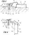
Fig. 3 is a cross-sectional view illustrating a state of the drug injection device according to the first embodiment of the present invention during puncture. -
Fig. 4 is a cross-sectional view illustrating a state of the drug injection device according to the first embodiment of the present invention after puncture. -
Fig. 5 is a cross-sectional view illustrating a state of the drug injection device according to the first embodiment of the present invention after puncture. -
Fig. 6 is a cross-sectional view illustrating a drug injection device according to a second embodiment of the present invention. -
Fig. 7 is a cross-sectional view illustrating a drug injection device according to a third embodiment of the present invention. - Hereinafter, embodiments of the injection needle assembly and the drug injection device of the present invention will be described with reference to
Figs. 1 to 7 . In the drawings, the same members are denoted by the same reference numerals. The present invention is not limited to the embodiments described below. - The embodiments will be described in the following order.
- 1. First Embodiment
- 1-1. Configuration example of injection needle assembly and drug injection device
- 1-2. Method of using drug injection device
- 2. Second Embodiment
- 3. Third Embodiment
- First, a drug injection device and an injection needle assembly according to the first embodiment of the present invention (hereinafter referred to as "the present embodiment") will be described with reference to
Figs. 1 and2 . -
Fig. 1 is a perspective view illustrating a drug injection device of the present embodiment.Fig. 2 is a cross-sectional view illustrating an injection needle assembly of the present embodiment. - The drug injection device 1 is used when puncturing a skin surface with a needle tip and injecting drug into a skin upper layer region.
- Here, the skin is composed of three portions: the epidermis, the dermis, and the subcutaneous tissue. The epidermis is a layer of about 50 to 200 µm ranging from the surface of the skin, and the dermis is a layer of about 1.5 to 3.5 mm continuing from the epidermis. An influenza vaccine is ordinarily administered subcutaneously or intramuscularly, and, therefore, it is injected into a lower layer portion of the skin or a portion deeper than the lower layer portion.
- To reduce doses of the influenza vaccine, administration of the vaccine while taking as a target region a skin upper layer region where a lot of immunocytes are present has been investigated. The term "skin upper layer region" used here means the epidermis and the dermis, of the skin. The drug injection device 1 of the present embodiment is the drug injection device 1 for intradermal injection whose target region is such a skin upper layer region.
- As illustrated in
Fig. 1 , the drug injection device 1 has an injection needle assembly 2, asyringe 103 that is detachably attached to the injection needle assembly 2, apusher member 104, and asyringe holder 105 that holds thesyringe 103. - The
syringe 103 is a pre-filled syringe that is filled with a drug in advance. Thesyringe 103 has a syringemain body 111, a discharge portion that is formed at one end portion in an axial direction of the syringemain body 111, alock mechanism 112 provided to the discharge portion, and agasket 113. - The syringe
main body 111 is formed into a hollow and substantially cylindrical shape. Thegasket 113 is slidably arranged inside a cylindrical hole of the syringemain body 111. Thegasket 113 is formed into a substantially columnar shape and is closely and liquid-tightly attached to an inner circumferential surface of the cylindrical hole of the syringemain body 111. Thegasket 113 partitions an internal space of the syringemain body 111 into two. A space from thegasket 113 toward the discharge portion in the syringemain body 111 is aliquid chamber 114 that is filled with a drug. On the other hand, in a space from thegasket 113 toward the other end in the syringemain body 111, a plungermain body 116 of thepusher member 104 described later is inserted. - Though a material of the
gasket 113 is not limited in particular, it is preferable that thegasket 113 is formed of an elastic material to achieve good liquid-tightness with the syringemain body 111. Examples of the elastic material include various rubber materials such as natural rubber, isobutylene rubber, and silicone rubber, various thermoplastic elastomers such as olefinic elastomer and styrene elastomer, and a mixture thereof and the like. - The outer and inner diameters of the syringe
main body 111 are appropriately set according to purpose of use of the drug injection device 1 and the amount of drug contained in theliquid chamber 114. For example, when the amount of drug contained by using a general-purpose high-speed filling machine is 0.5 mL, it is preferable to set the inner diameter of the syringemain body 111 to 4.4 to 5.0 mm and set the outer diameter of the syringemain body 111 to 6.5 to 8.4 mm. Further, when the amount of drug is 1 mL, it is preferable to set the inner diameter of the syringemain body 111 to 6.1 to 9.0 mm and set the outer diameter of the syringemain body 111 to 7.9 to 12.5 mm. - Examples of the drug include various vaccines that prevent various infectious diseases such as influenza. However, the drug is not limited to vaccines. Examples of the drug other than vaccines include carbohydrate injection solution such as glucose, electrolyte correction injection solution such as sodium chloride, potassium lactate, and the like, vitamin preparations, antibiotic injection solution, imaging agent, steroid drug, proteolytic enzyme inhibitor, fat emulsion, anticancer drug, anesthetics, heparin calcium, and antibody drug.
- A
flange portion 115 is formed at the other end portion in the axial direction of the syringemain body 111. Theflange portion 115 is engaged with an engagingportion 105a provided to thesyringe holder 105 described later. The discharge portion not illustrated in the drawings is continuously formed at the one end portion in the axial direction of the syringemain body 111. - The discharge portion is formed into a substantially cylindrical shape coaxial with the syringe
main body 111. A cylindrical hole of the discharge portion communicates with the cylindrical hole of the syringemain body 111. The discharge portion is formed into a tapered shape whose diameter is continuously reduced toward one end in an axial direction. When the injection needle assembly 2 is attached to thesyringe 103, a distal end portion of the discharge portion liquid-tightly comes into contact with an end face of anelastic member 61 of the injection needle assembly 2 described later. - The
lockmechanism 112 is provided to the discharge portion. Thelock mechanism 112 is a luer lock unit representing an example of a fixing mechanism. Thelock mechanism 112 is formed into a tubular shape that coaxially surrounds the discharge portion. Thelock mechanism 112 is formed into a shape whose inner circumference has a circular shape and whose outer circumference has a hexagonal shape. A female screw portion is formed on an inner circumferential surface of thelock mechanism 112. The female screw portion is formed so as to be able to be screwed with amale screw portion 35 provided on the injection needle assembly 2. - Examples of a material of the syringe
main body 111 include various resins such as polyvinyl chloride, polyethylene, polypropylene, cyclic polyolefin, polystyrene, poly-(4-methylpentene-1), polycarbonate, acrylic resin, acrylonitrile-butadiene-styrene copolymer, polyester including polyethylene terephthalate, butadiene-styrene copolymer, and polyamide (for example,nylon 6,nylon nylon main body 111 is preferred to be substantially transparent to secure internal visibility. - In the present embodiment, an example has been described where a pre-filled syringe that is filled with a drug in advance is applied as the
syringe 103. However, the syringe is not limited to this, and a syringe whose syringe main body is not filled with a drug in advance may be applied. - The
pusher member 104 has a plungermain body 116 and anoperation portion 117 that operates the plungermain body 116. The plungermain body 116 is formed into a rod shape. The plungermain body 116 is inserted into the cylindrical hole of the syringemain body 111 through an opening portion formed at the other end portion in the axial direction of the syringemain body 111. Then, one end portion in the axial direction of the plungermain body 116 comes into contact with thegasket 113. - The
operation portion 117 is formed at the other end portion in the axial direction of the plungermain body 116. Theoperation portion 117 is formed into a substantially disk shape. When the drug injection device 1 is used, theoperation portion 117 is pressed by a user. Thereby, the one end portion in the axial direction of the plungermain body 116 comes into contact with thegasket 113 to cause thegasket 113 to slide toward the discharge portion. - As a material of the
pusher member 104, the various resins included as the examples of a material of the syringemain body 111 can be used. - Next, the
syringe holder 105 will be described. - The
syringe holder 105 is formed into a substantially cylindrical shape. Thesyringe holder 105 covers the outer circumferential surface of the syringemain body 111 and the outer circumferential surface of thelock mechanism 112 in thesyringe 103. Thesyringe holder 105 is formed so as to be held by a user when the user attaches the injection needle assembly 2 to thesyringe 103. - A
view window 118 is formed at one end portion in the axial direction of thesyringe holder 105. Theview window 118 is provided at a position from which theliquid chamber 114 of thesyringe 103 can be viewed from the outside of thesyringe holder 105 when thesyringe 103 is inserted into thesyringe holder 105. Thereby, it is possible to secure internal visibility even when thesyringe holder 105 is attached to thesyringe 103. - A
holder brim portion 119 is formed at the other end in the axial direction of thesyringe holder 105. Theholder brim portion 119 projects substantially perpendicularly from a part of the outer circumferential surface of thesyringe holder 105. The holder brimportion 119 is provided, and thereby it is possible to prevent fingers that hold thesyringe holder 105 from slipping toward the other end portion in the axial direction when the user holds thesyringe holder 105 and administers a drug. Further, when the drug injection device 1 is placed on a desk, a table, or the like, it is possible to prevent the drug injection device 1 from rolling. - Further, an engaging
portion 105a is provided in a middle portion in the axial direction of thesyringe holder 105. The engagingportion 105a is an opening portion that penetrates an outer wall of thesyringe holder 105. Theflange portion 115 of thesyringe 103 is engaged with the engagingportion 105a. - When the
syringe holder 105 is attached to thesyringe 103, the diameter of the drug injection device 1 can be increased, so that it is possible to easily hold the drug injection device 1. Thereby, operability when operating thepusher member 104 is improved. - Next, the injection needle assembly 2 will be described.
- As illustrated in
Figs. 1 and2 , the injection needle assembly 2 has ahollow needle tube 5 having a needle hole, aneedle hub 6 to which theneedle tube 5 is fixed, and alid member 40 that covers theneedle tube 5 after puncture. - As illustrated in
Fig. 2 , as theneedle tube 5, a needle tube having a size of 26 to 33 gauge (outer diameter is 0.2 to 0.45 mm) in ISO standard for medical needle tubes (ISO9626: 1991/Amd. 1:2001(E)) is used, and preferably a needle tube having a size of 30 to 33 gauge is used. A needle smaller than 33 gauge may also be used. - A
needle tip 5A having ablade surface 5a is provided at one end of theneedle tube 5. Hereinafter, a portion located opposite to theneedle tip 5A is referred to as a proximal end of theneedle tube 5. The length in the axial direction of theneedle tube 5 on theblade surface 5a (hereinafter referred to as a "bevel length B") may be smaller than or equal to 1.4 mm (adults), which is the smallest thickness of a skin upper layer region described later, and may be greater than or equal to 0.5 mm, which is a bevel length when a short bevel is formed on a needle tube of 33 gauge. In short, the bevel length B is preferably set in a range of 0.5 to 1.4 mm. - Further, it is more preferable that the smallest thickness of the skin upper layer region is smaller than or equal to 0.9 mm (infants), that is, the bevel length B is in a range of 0.5 to 0.9 mm. The short bevel means a blade surface that forms an angle of 18 to 25° with respect to the longitudinal direction of the needle, which is generally used for an injection needle.
- The material of the
needle tube 5 may be, for example, stainless steel, but this is not limitative. Examples of other usable materials include such metals as aluminum, aluminum alloys, titanium, and titanium alloys. In addition, theneedle tube 5 is not limited to a straight needle but may be a tapered needle which is tapered at least along a portion of its length. The tapered needle may be one in which the diameter of the proximal end portion of the needle is greater than the distal end portion, with an intermediate part having a tapered structure. The cross-sectional shape of theneedle tube 5 is not limited to a circle but may be a polygon such as a triangle. - Next, the
needle hub 6 will be described. - The
needle hub 6 includes afirst member 11 that holds theneedle tube 5, asecond member 12 into which the discharge portion of thesyringe 103 is fitted, and anelastic member 61. Although thefirst member 11 and thesecond member 12 are formed as separate members, they can be integrally formed. Examples of material (s) of thefirst member 11 and thesecond member 12 include synthetic resins such as polycarbonate, polypropylene, polyethylene, and the like. - The
first member 11 includes abase portion 15, anadjustment portion 16, astabilization portion 17, and aguide portion 18. Thebase portion 15 is formed into a substantially columnar shape, and has end faces 15a and 15b perpendicular to the axial direction. Theadjustment portion 16 is provided at a central portion of theend face 15a of thebase portion 15, and is composed of a columnar projected portion projecting in the axial direction of thebase portion 15. The axial center of theadjustment portion 16 coincides with the axial center of thebase portion 15. - A through-
hole 21 through which theneedle tube 5 penetrates is provided at the axial center of thebase portion 15 and theadjustment portion 16. Thebase portion 15 includes an injection hole 22 (seeFigs. 2 and4 ) for injecting an adhesive 20 (seeFig. 3 ) into the through-hole 21. Theinjection hole 22 opens to the outer circumferential surface of thebase portion 15, and communicates with the through-hole 21. By virtue of the adhesive 20 injected through theinjection hole 22 into the through-hole 21, theneedle tube 5 is fixed to thebase portion 15. - The proximal end of the
needle tube 5 protrudes from theend face 15b of thebase portion 15. Thebase portion 15 is inserted into thesecond member 12 from theend face 15b, and the proximal end of theneedle tube 5 is inserted into an insertion hole of theelastic member 61. Then, theend face 15b of thebase portion 15 comes into contact with theelastic member 61. - The outer circumferential surface of the
base portion 15 includes aconnectionpiece 24. Theconnectionpiece 24 is formed as a ring-shaped flange projecting in the radial directions of thebase portion 15, and hasflat surfaces base portion 15. Thesecondmember 12 is connected to theflat surface 24b of theconnection piece 24. In addition, a tip portion of theconnection piece 24 constitutes aguide portion 18. Theguide portion 18 will be described in detail later. - An end face of the
adjustment portion 16 constitutes aneedle protrusion surface 16a from which theneedle tip 5A of theneedle tube 5 protrudes. Theneedle protrusion surface 16a is formed as a flat surface orthogonal to the axial direction of theneedle tube 5. When theneedle tube 5 is positioned to puncture the skin upper layer region, theneedle protrusion surface 16a contacts the surface of the skin to determine a puncture depth of theneedle tube 5. Specifically, the depth of puncture of theneedle tube 5 into the skin upper layer region is determined by the length of a portion of theneedle tube 5 which protrudes from theneedle protrusion surface 16a (this length will hereinafter be referred to as a "protrusion length L"). - The thickness of the skin upper layer region corresponds to a depth ranging from the surface of the skin to the dermis layer, and it is in a range of approximately 0.5 to 3.0 mm. Therefore, the protrusion length L of the
needle tube 5 can be set in a range of 0.5 to 3.0 mm. - Vaccines are generally administered into an upper arm region, and, in the case of administration into a skin upper layer region, the target site is preferably a thick-skinned shoulder peripheral region, particularly, a deltoid region. In view of this, the thickness of the skin upper layer region at the deltoid muscle was measured, for 19 infants and 31 adults. The measurement was conducted by imaging the skin upper layer region where ultrasonic reflectance is high, by use of an ultrasonic measuring instrument (NP60R-UBM, a high-resolution echo system for small animals, produced by NEPA GENE CO. , LTD.). The measurements were in log normal distribution and, therefore, the range of MEAN ± 2SD was determined by use of geometric mean.
- As a result, the thickness of the skin upper layer region at the deltoid muscles of infants was found to be 0.9 to 1.6 mm. The thickness of the skin upper layer region at the deltoid muscles of adults was found to be 1.4 to 2.6 mm in a distal region, 1.4 to 2. 5 mm in a central region, and 1. 5 to 2.5 mm in a proximal region. From these measurements, it was confirmed that the thickness of the skin upper layer region at the deltoid muscle is not less than 0.9 mm in infants, and not less than 1.4 mm in adults. Accordingly, it is preferable that the protrusion length L of the
needle tube 5, in injection into the skin upper layer region at the deltoid muscle, is set in a range of 0.9 to 1.4 mm. - By setting the protrusion length L in this manner, the
blade surface 5a of theneedle tip 5A can be securely positioned in the skin upper layer region. As a result, a needle hole (medicine discharge port) opening at theblade surface 5a can be located in the skin upper layer region, irrespective of the position of the needle hole on theblade surface 5a. Even when the medicine discharge port is located in the skin upper layer region, the medicine will flow into a subcutaneous region through a gap between a side surface of an end portion of theneedle tip 5A and an incised skin if theneedle tip 5A pierces to a position deeper than the skin upper layer region. Therefore, it is important that theblade surface 5a is securely located within the skin upper layer region. - In the case of a needle tube thicker than 26 gauge, it is difficult to set the bevel length B to be not more than 1.0 mm. In order to set the protrusion length L of the
needle tube 5 to be within the preferable range (0.9 to 1.4 mm), therefore, it is preferable to use a needle tube thinner than 26 gauge. - The
needle protrusion surface 16a is so formed that a distance S from its circumferential edge to the outer circumferential surface of theneedle tube 5 is not more than 1.4 mm, preferably in a range of 0.3 to 1.4 mm. This distance S from the circumferential edge of theneedle protrusion surface 16a to the outer circumferential surface of theneedle tube 5 is determined by taking into account that a pressure is exerted on a wheal or blister formed by injection of the medicine into the skin upper layer region. Specifically, theneedle protrusion surface 16a is set to be sufficiently smaller than the wheal or blister to be formed in the skin upper layer region and, hence, does not inhibit the formation of the wheal or blister. As a result, even when theneedle protrusion surface 16a presses against the skin in the surroundings of theneedle tube 5, the medicine being injected can be prevented from leaking. - The
stabilization portion 17 is formed into a tubular shape that protrudes from theflat surface 24a of theconnection piece 24 provided on thebase portion 15. Theneedle tube 5 and theadjustment portion 16 are disposed in a cylindrical hole of thestabilization portion 17. In other words, thestabilization portion 17 is formed into a cylindrical shape that covers the surrounding of the adj ustmentportion 16 penetrated by theneedle tube 5, and is provided radially separated from theneedle tip 5A of theneedle tube 5. - As shown in
Fig. 3 , anend face 17a of thestabilization portion 17 is located on the proximal end side of theneedle tube 5 relative to theneedle protrusion surface 16a of theadjustment portion 16. When theneedle tip 5A of theneedle tube 5 punctures a living body, theneedle protrusion surface 16a first comes into contact with the surface of the skin, and thereafter the surface of the skin touches theend face 17a of thestabilization portion 17. In this instance, the contact of theend face 17a of thestabilization portion 17 with the skin helps stabilize the drug injection device 1, whereby theneedle tube 5 can be kept in a posture of being substantially perpendicular to the skin. - When the
end face 17a of thestabilization portion 17 is located on the same plane as theneedle protrusion surface 16a, or is located on the side of theneedle tip 5A of theneedle tube 5 relative to theneedle protrusion surface 16a, theneedle tube 5 can be maintained in a posture of being substantially perpendicular to the skin. Taking into account the bulging of the skin when thestabilization portion 17 is pressed against the skin, the distance between theend face 17a of thestabilization portion 17 and theneedle protrusion surface 16a along the axial direction is preferably set to be not more than 1.3 mm. - In addition, an inside diameter d of the
stabilization portion 17 is set to a value equal to or greater than the diameter of the wheal or blister to be formed in the skin. Specifically, the inside diameter d of thestabilization portion 17 is so set that a distance T from the inner wall surface of thestabilization portion 17 to the outer circumferential edge of theneedle protrusion surface 16a is in a range of 4 to 15 mm. Thereby, it is possible to prevent hindrance of wheal/blister formation due to exertion of a pressure on the wheal/blister from the inner wall surface of thestabilization portion 17. - It suffices that the distance T from the inner wall surface of the
stabilization portion 17 to the circumferential edge of theneedle protrusion surface 16a is not less than 4 mm, and there is no upper limit for the distance T. However, an increase in the distance T causes an increase in the outer diameter of thestabilization portion 17, which makes it difficult to bring the whole portion of theend face 17a of thestabilization portion 17 into contact with the skin in the case where theneedle tube 5 is used to puncture a slender arm, such as an arm of an infant. Taking the slenderness of an infant's arm into account, therefore, it is preferable that the distance T is defined to be 15 mm at maximum. - When the distance S from the circumferential edge of the
needle protrusion surface 16a to the outer circumferential surface of theneedle tube 5 is not less than 0.3 mm, theadj ustment portion 16 will not enter into the skin. Taking into account the distance T (not less than 4 mm) from the inner wall surface of thestabilization portion 17 to the circumferential edge of theneedle protrusion surface 16a and the diameter (about 0.3 mm) of theneedle protrusion surface 16a, therefore, the inside diameter d of thestabilization portion 17 can be set to 9 mm or more. - The shape of the
stabilization portion 17 is not limited to a cylindrical shape. For example, the shape may be a cylinder with a polygonal sectional shape, such as a tetragonal prism, a hexagonal prism or the like having a cylindrical hole in the center thereof. - The
guide portion 18 is a portion of theconnection piece 24 which is located on the tip side relative to thestabilization portion 17. Theguide portion 18 has acontact surface 18a to be brought into contact with skin. Thecontact surface 18a is a part of theflat surface 24a of theconnection piece 24, and is a flat surface substantially parallel to theend face 17a of thestabilization portion 17. By pressing thestabilization portion 17 against skin until thecontact surface 18a of theguide portion 18 makes contact with the skin, a force with which thestabilization portion 17 and theneedle tube 5 are pressed against the skin can always be secured to be not less than a predetermined value. Thereby, a portion of theneedle tube 5 which protrudes from theneedle protrusion surface 16a (a portion corresponding to the protrusion length L) securely punctures the skin. - A distance (hereinafter referred to as "guide portion height") Y from the
contact surface 18a of theguide portion 18 to theend face 17a of thestabilization portion 17 is so set that theneedle tube 5 and thestabilization portion 17 can be pressed against skin with an appropriate pressure, resulting in appropriate puncture. Thereby, theguide portion 18 guides the pressure exerted on the skin by theneedle tube 5 and thestabilization portion 17, theneedle tip 5A (theblade surface 5a) of theneedle tube 5 can be securely located in the skin upper layer region, and the user can get a feeling of security. The appropriate pressure with which theneedle tube 5 and thestabilization portion 17 are pressed against the skin is, for example, 3 to 20 N. - When the inside diameter d of the
stabilization portion 17 is in a range of 11 to 14 mm, the guide portion height Y is appropriately determined based on a length (hereinafter referred to as "guide portion length") X from a tip surface of theguide portion 18 to the outer circumferential surface of thestabilization portion 17. For example, when the inside diameter d of thestabilization portion 17 is 12 mm and the guide portion length X is 3.0 mm, the guide portion height Y is set in a range of 2.3 to 6.6 mm. - Next, the
second member 12 will be described. Thesecond member 12 is formed into a tubular shape. One end portion in the axial direction of thesecond member 12 is aninsertion portion 31 in which thebase portion 15 of thefirst member 11 is to be inserted, and the other end portion is a fitting portion into which the discharge portion of thesyringe 103 is to be fitted. Acylindrical hole 31a of theinsertion portion 31 is sized correspondingly to thebase portion 15 of thefirst member 11. - A
fixation piece 34 is provided on the outer circumferential surface of one endportion in the axial direction of thesecond member 12 in theinsertion portion 31. Thefixation piece 34 is formed as a ring-shaped flange projecting radially outward continuously from the distal end of theinsertion portion 31. Theflat surface 24b of theconnection piece 24 provided on thefirst member 11 comes into contact with and is firmly attached to thefixation piece 34. Examples of a method for firmly attaching thefixation piece 34 and theconnection piece 24 to each other include adhesion with an adhesive, ultrasonic fusing, laser fusing, fixation with a fixation screw(s), and the like. - The outer diameter of the fitting portion is set to smaller than the outer diameter of the
insertion portion 31. Further, the cylindrical hole of the fitting portion is sized correspondingly to the discharge portion of thesyringe 103, and the diameter of the cylindrical hole continuously decreases toward theinsertion portion 31. Amale screw portion 35 for screwing with thelockmechanism 112 of thesyringe 103 is provided on the outer circumferential surface of the fitting portion (seeFig. 1 ). Theelastic member 61 is arranged between thecylindrical hole 31a of theinsertion portion 31 and the cylindrical hole of the fitting portion. - Next, the
elasticmember 61 will be described. Theelastic member 61 is formed of an elastically deformable member. Examples of the material of theelastic member 61 include elastic materials such as various rubber materials such as natural rubber, silicone rubber, isobutylene rubber, etc., various thermoplastic elastomers based on polyurethane, styrene, or the like, and mixtures thereof. - The
elastic member 61 is disposed inside thesecond member 12, and is interposed between thefirst member 11 and thesyringe 103. Theelastic member 61 thus fills up a gap generated between the outer circumferential surface on the proximal end side of theneedle tube 5 protruded from thefirst member 11 and thesecond member 12. When the discharge portion of thesyringe 103 is fitted into thesecond member 12, theelastic member 61 is elastically deformed, so that theelastic member 61 is closely and liquid-tightly attached to the outer circumference of theneedle tube 5. Thereby, it is possible to prevent a drug filled in thesyringe 103 from penetrating between theneedle tube 5 and theelastic member 61 to leak to thefirst member 11 side. - Next, the
lid member 40 will be described. Thelid member 40 is provided on a radially outer edge portion of theguide portion 18 in theneedle hub 6. Thelid member 40 has amain body portion 41, a connectingportion 42, and an energizingportion 43. - The
main body portion 41 is formed into a substantially cylindrical shape. Themain body portion 41 has atop plate 44 having a circular shape and aside wall portion 45 that is bent substantially perpendicular from the edge portion of thetop plate 44 and is continuously formed along the circumferential direction of thetop plate 44. - The diameter of the
top plate 44 is set to larger than the outer diameter of thestabilization portion 17. The length of theside wall portion 45, that is, the length in the axial direction of themain body portion 41, is set to longer than the guide portion height Y and the length of theneedle tube 5 protruded from theadjustment portion 16. In other words, themain body portion 41 is formed into a size that can cover and enclose the whole of theneedle tip 5A of theneedle tube 5, theadjustment portion 16, and the stabilization portion 17 (seeFig. 5 ). Themain body portion 41 is connected to theneedle hub 6 through the connectingportion 42. - The connecting
portion 42 is provided to the outer edge portion of theguide portion 18. A portion of the connectingportion 42 which is connected to theguide portion 18 is athin portion 42a whose thickness is smaller than other portions. The connectingportion 42 rotatably supports themain body portion 41 with thethin portion 42a as a supporting point. The energizingportion 43 is arranged between the connectingportion 42 and theneedle hub 6. - The energizing
portion 43 is formed by a plate spring having elasticity. The energizingportion 43 includes a plurality of linear portions and bent portions each of which is provided between the linear portions, inFig. 2 showing a cross section. In the present embodiment, three linear portions and two bent portions are provided. Energization force is accumulated in the energizingportion 43 when, for example, the linear portion is deformed or a bending angle of the bent portion is changed. One end portion in the longitudinal direction of the energizingportion 43 is fixed to thetop plate 44 of themain body portion 41. The other end portion in the longitudinal direction of the energizingportion 43 is fixed to theinsertion portion 31 of thesecond member 12 in theneedle hub 6. - The portions to which the energizing
portion 43 is fixed are not limited to the portions described above. For example, the one end portion in the longitudinal direction of the energizingportion 43 may be fixed to theside wall portion 45 of themain body portion 41 and the other end portion in the longitudinal direction of the energizingportion 43 may be fixed to thefixation piece 34 of thesecond member 12. That is to say, the one end portion in the longitudinal direction of the energizingportion 43 may be fixed to themain body portion 41 and the other end portion in the longitudinal direction of the energizingportion 43 may be fixed to any piece of theneedle hub 6. Further, the energizingportion 43 need not be a portion having linear portions and bent portions, but may be a portion that is curved as a whole (C shape, U shape, and the like) or may be a portion having a combination of these shapes. - In a state before the puncture illustrated in
Fig. 2 is performed, the connectingportion 42 and the energizingportion 43 hold themain body portion 41 in a state in which at least a prat of themain body portion 41 protrudes to the distal end side in the axial direction of theneedle hub 6 relative to thecontact surface 18a of theneedle hub 6, that is, to theneedle tip 5A side of theneedle tube 5. In the present embodiment, in an end portion of the opening side of themain body portion 41, a portion farthest away from the connectingportion 42 protrudes to the distal end side in the axial direction of theneedle hub 6 relative to thecontact surface 18a. In other words, anend face 41a of the opening side of themain body portion 41, that is, an end face of theside wall portion 45 opposite to thetop plate 44, is inclined relative to thecontact surface 18a. - In the present embodiment, an example has been described where the
main body portion 41 is formed into a cylindrical shape. However, the shape of themain body portion 41 is not limited to this, and for example, the shape may be a cylinder with a polygonal sectional shape, such as a tetragonal prism, a hexagonal prism or the like having a cylindrical hole in the center thereof. Further, themain body portion 41 only has to cover theneedle tip 5A of theneedle tube 5, so that the main body portion may be formed into a flat plate shape and a part of theneedle tip 5A of theneedle tube 5 may puncture the main body portion or bend. - 1-2. Method of using drug injection device
- Next, a method of using the drug injection device 1 having the configuration described above will be described with reference to
Figs. 1 to 5 . -
Fig. 3 is a cross-sectional view illustrating main parts of the drug injection device 1 during puncture.Figs. 4 and5 are cross-sectional views illustrating main parts of the drug injection device 1 after puncture. - First, as illustrated in
Figs. 1 and2 , thesyringe 103 is attached to the injection needle assembly 2. Specifically, the discharge portion of thesyringe 103 is inserted into the fitting portion of thesecond member 12 and thelock mechanism 112 is screwed with themale screw portion 35. Thereby, the injection needle assembly 2 has been attached to thesyringe 103. As illustrated inFig. 2 , themain body portion 41 of thelid member 40 is away from theneedle tip 5A of theneedle tube 5, and theneedle tip 5A of theneedle tube 5 is exposed. The position of themain body portion 41 at this time is defined as a first position. - Next, the
end face 17a of thestabilization portion 17 is positioned to oppose the skin. This results in theneedle tip 5A of theneedle tube 5 being opposed to the skin to be punctured. Next, the drug injection device 1 is moved substantially perpendicularly to the skin to puncture the skin with theneedle tip 5A and, simultaneously, press theend face 17a of thestabilization portion 17 against the skin. In this instance, theneedle protrusion surface 16a contacts the skin, whereby the skin can be deformed to be flat, and theneedle tip 5A side of theneedle tube 5 can puncture the skin by the protrusion length L. - Next, the
end face 17a of thestabilization portion 17 is pressed against the skin until thecontact surface 18a of theguide portion 18 comes into contact with the skin. Here, the guide portion height Y is set to such a value that the skin is punctured while theneedle tube 5 and thestabilizationportion 17 are being pressed against the skin with proper pressures. Therefore, the pressure with which thestabilization portion 17 presses the skin is set to a predetermined value. - As a result, the user can recognize the proper pressure relevant to the
stabilization portion 17, and can locate theneedle tip 5A and theblade surface 5a of theneedle tube 5 securely in the skin upper layer region. With theguide portion 18 thus serving as a mark for permitting recognition of the proper pressure relevant to thestabilization portion 17, the user can use the drug injection device 1 without anxiety. - In addition, with the
stabilization portion 17 coming into contact with the skin, the posture of the drug injection device 1 is stabilized, and theneedle tube 5 can puncture the skin in a straight manner. Further, it is possible to prevent theneedle tube 5 from being moved after puncture, so that the drug can be injected stably. - Further, in the case of a needle tube having an extremely small protrusion length of, for example, about 0. 5 mm, the needle tip may fail to pierce skin even when brought into contact with the skin. When the skin pressed by the
stabilization portion 17 is pressed down perpendicularly, however, the skin on the inner side of thestabilization portion 17 is pulled, resulting in tension being applied to the skin. Therefore, theskinbecomes less liable to escape from theneedle tip 5A of theneedle tube 5. Accordingly, it is also possible to obtain an effect that theneedle tip 5A more easily punctures the skin by providing thestabilization portion 17. - At least a part of the
main body portion 41 of thelid member 40 protrudes to the distal end side in the axial direction of theneedle hub 6 relative to thecontact surface 18a. Therefore, theend face 41a of themain body portion 41 comes into contact with the skin before thecontact surface 18a comes into contact with the skin. As described above, by pressing the injection needle assembly 2 until thecontact surface 18a comes into contact with the skin, themain body portion 41 rotates in a direction in which themain body portion 41 goes away from theneedle tip 5A of theneedle tube 5 with thethin portion 42a of the connectingportion 42 as a supporting point. As a result, theend face 41a of themain body portion 41 becomes parallel with thecontact surface 18a. - When the
main body portion 41 rotates in a direction in which themain body portion 41 goes away from theneedle tip 5A of theneedle tube 5, the energizingportion 43 is elastically deformed, so that a linear portion in the energizingportion 43 may be deformed or a bending angle of a bent portion may be changed. Therefore, the energization force is accumulated in the energizingportion 43. - After puncturing the skin with the
needle tip 5A of theneedle tube 5, thegasket 113 is moved toward the discharge portion by pressing the pusher member 104 (seeFig. 1 ). Thereby, the drug filled in theliquid chamber 114 of thesyringe 103 is pushed out from the discharge portion and injected into the skin upper layer region from theneedle tip 5A through the needle hole of theneedle tube 5. In this instance, no space is formed between the distal end of the discharge portion and the proximal end of theneedle tube 5, so that it is possible to reduce the remaining amount of the drug. - Next, as illustrated in
Fig. 4 , the drug injection device 1 is separated from the skin to cause theend face 17a of thestabilization portion 17, theneedle protrusion surface 16a, and theend face 41a of themain body portion 41 to go away from the skin. In this instance, the pressure from the skin to the energizingportion 43 through themain body portion 41 is released. Then, themain body portion 41 is pressed by a restoring force (energization force) of the energizingportion 43 to rotate in a direction to approach theneedle tip 5A of theneedle tube 5 with thethin portion 42a of the connectingportion 42 as a supporting point. - Then, as illustrated in
Fig. 5 , theend face 41a of themain body portion 41 comes into contact with or approaches thecontact surface 18a, so that the rotation action of themain body portion 41 stops. Thereby, theneedle tip 5A of theneedle tube 5, theadjustment portion 16, and thestabilization portion 17 are covered and enclosed by themain body portion 41. The position where themain body portion 41 most approaches theneedle tip 5A of theneedle tube 5 is defined as a second position. Then, a finger or the like is prevented from touching theneedle tip 5A of theneedle tube 5 after puncture by themain body portion 41. - As a result, it is possible to keep the
needle tip 5A of theneedle tube 5 that has been used in a safe state and it is possible to prevent the usedneedle tip 5A of theneedle tube 5 from puncturing a user against the intention of the user. Further, the usedneedle tip 5A of theneedle tube 5 is covered by themain body portion 41, so that it is possible to prevent blood attached to theneedle tip 5A from scattering, and it is also possible to prevent blood-borne infection. - Regarding the
lid member 40 of the present embodiment, when the drug injection device 1 is separated from the skin, themain body portion 41 is automatically rotated by the energization force accumulated in the energizingportion 43. As a result, it is possible to prevent omission of closing of themain body portion 41, and it is also possible to prevent a finger or the like from erroneously touching theneedle tip 5A of theneedle tube 5 when rotating themain body portion 41. - After the puncture, the energizing
portion 43 of the rotatedlid member 40 energizes themain body portion 41 in a direction in which theend face 41a of themain body portion 41 is pressed against thecontact surface 18a. Thereby, it is possible to prevent themain body portion 41 from rotating in a direction in which themain body portion 41 goes away from theneedle tip 5A of theneedle tube 5 against the intention of the user and prevent theneedle tip 5A of theneedle tube 5 from being exposed. - Next, a drug injection device according to the second embodiment will be described with reference to
Fig. 6 . -
Fig. 6 is an enlarged cross-sectional view illustrating main parts of the drug injection device according to the second embodiment. - The difference between the drug injection device according to the second embodiment and the drug injection device 1 according to the first embodiment is a configuration of the lid member in the injection needle assembly. Therefore, here, the lid member will be mainly described, and the same portions as those of the injection needle assembly 2 according to the first embodiment will be denoted by the same reference numerals and redundant description will be omitted.
- As illustrated in
Fig. 6 , theinjection needle assembly 2A has thehollow needle tube 5, theneedle hub 6 that holds theneedle tube 5, and alid member 70. - The
lid member 70 has amain body portion 71 having a substantially cylindrical shape, a connecting portion 72, and an energizingportion 73. Themain body portion 71 has atop plate 74 having a circular shape, aside wall portion 75, and acontact protrusion 76. - The
contact protrusion 76 is arranged at a position farthest away from the connecting portion 72 on anend face 71a of themain body portion 71. Thecontact protrusion 76 protrudes from theend face 71a in a direction going away from thetop plate 74. - The
main body portion 71 is rotatably supported by the connecting portion 72. In a state before the puncture is performed, the connecting portion 72 and the energizingportion 73 hold themain body portion 71 so that theend face 71a of themain body portion 71 becomes substantially in parallel with thecontact surface 18a. Therefore, thecontact protrusion 76 protrudes to the distal end side in the axial direction of theneedle hub 6 relative to thecontact surface 18a. - When the drug injection device having such a
lid member 70 is pressed against the skin, thecontact protrusion 76 of themain body portion 71 comes into contact with the skin before thecontact surface 18a comes into contact with the skin. When theinjection needle assembly 2A is pressed until thecontact surface 18a comes into contact with the skin, themain body portion 71 rotates in a direction in which themain body portion 71 goes away from theneedle tip 5A of theneedle tube 5 with a thin portion 72a of the connecting portion 72 as a supporting point. As a result, the energizingportion 73 is elastically deformed and the energization force is accumulated in the energizingportion 73. - A fitting recessed
portion 18b into which thecontact protrusion 76 of the rotatedlid member 70 is fitted is provided in thecontact surface 18a of theguide portion 18. Thereby, it is possible to prevent thelid member 70 that has rotated to cover and enclose theneedle tip 5A of theneedle tube 5, theadjustment portion 16, and thestabilization portion 17 from rotating again. - The other portions are the same as those of the injection needle assembly 2 according to the first embodiment, so that the description thereof will be omitted. When the
lid member 70 having the configuration as described above is provided to theinjection needle assembly 2A, it is possible to obtain the same functional effect as that of the injection needle assembly 2 according to the first embodiment described above. - Next, a drug injection device according to the third embodiment will be described with reference to
Fig. 7 . -
Fig. 7 is an enlarged cross-sectional view illustrating main parts of the drug injection device according to the third embodiment. - The difference between the drug injection device according to the third embodiment and the drug injection device 1 according to the first embodiment is a configuration of the lid member in the injection needle assembly. Therefore, here, the lid member will be mainly described, and the same portions as those of the injection needle assembly 2 according to the first embodiment will be denoted by the same reference numerals and redundant description will be omitted.
- As illustrated in
Fig. 7 , theinjection needle assembly 2B has thehollow needle tube 5, theneedle hub 6 that holds theneedle tube 5, and alid member 80. - The
lid member 80 has a firstmain body portion 81A, a first connectingportion 82A, a first energizingportion 83A, a secondmain body portion 81B, a second connectingportion 82B, and a second energizingportion 83B. The firstmain body portion 81A, the first connectingportion 82A, and the first energizingportion 83A are provided to an outer edge portion of theguide portion 18. The secondmain body portion 81B, the second connectingportion 82B, and the second energizingportion 83B are provided to an outer edge portion of theguide portion 18 opposite to the firstmain body portion 81A, the first connectingportion 82A, and the first energizingportion 83A with theguide portion 18 in between. - The configuration of the second
main body portion 81B, the second connectingportion 82B, and the second energizingportion 83B is the same as that of the firstmain body portion 81A, the first connectingportion 82A, and the first energizingportion 83A. Therefore, here, the firstmain body portion 81A, the first connectingportion 82A, and the first energizingportion 83A will be described. - The first
main body portion 81A is formed into a substantially semi-cylindrical shape. The firstmain body portion 81A has a substantially semicirculartop plate 84 and aside wall portion 85. The firstmain body portion 81A is rotatably supported by the first connectingportion 82A. In a state before the puncture is performed, the first connectingportion 82A and the first energizingportion 83A hold the firstmain body portion 81A so that at least a part of the firstmain body portion 81A protrudes to the distal end side in the axial direction of theneedle hub 6 relative to thecontact surface 18a. - After the puncture, the
lidmember 80 rotates in a direction in which the firstmain body portion 81A and the secondmain body portion 81B approach theneedle tip 5A of theneedle tube 5. Then, theneedle tip 5A of theneedle tube 5 is covered and enclosed by the firstmain body portion 81A and the secondmain body portion 81B. - The other portions are the same as those of the injection needle assembly 2 according to the first embodiment, so that the description thereof will be omitted. When the
lid member 80 having the configuration as described above is provided to theinjection needle assembly 2B, it is possible to obtain the same functional effect as that of the injection needle assembly 2 according to the first embodiment described above. - According to the
lid member 80 of the third embodiment, the main body portion is divided into two portions, which are the firstmain body portion 81A and the secondmain body portion 81B. Even when theneedle tube 5 is used to puncture a slender arm, such as an arm of an infant, it is possible to reliably press either of the firstmain body portion 81A or the secondmain body portion 81B against the skin. As a result, after the puncture, at least either of the firstmain body portion 81A or the secondmain body portion 81B can be rotated, so that it is possible to reliably cover theneedle tip 5A of theneedle tube 5. - The embodiments of the drug injection device and the injection needle assembly and also the functional effects thereof have been described. However, the drug injection device and the injection needle assembly of the present invention are not limited to the embodiments described above, but various modifications are possible without departing from the scope of the invention set forth in the claims.
- In the embodiments described above, an example is described where the luer lock unit is provided as the
lock mechanism 112, but this is not limitative. The discharge portion and the injection needle assembly may be screwed together by providing a male screw portion to the discharge portion and providing a female screw portion to the cylindrical hole of thesecondmember 12 of the injection needle assembly. - 1: drug injection device, 2, 2A, 2B: injection needle assembly, 5: needle tube, 5A: needle tip, 5a: blade surface, 6: needle hub, 11: first member, 12: second member, 13: gasket, 15: base portion, 16: adjustment portion, 16a: needle protrusion surface, 17: stabilization portion, 17a: end face, 18: guide portion, 18a: contact surface, 18b: fitting recessed portion, 40, 70, 80: lid member, 41, 71: main body portion, 41a, 71a: end face, 42, 72: connecting portion, 42a, 72a: thin portion, 43, 73: energizing portion, 44, 74, 84: top plate, 45, 75, 85: side wall portion, 76: contact protrusion, 81A: first main body portion, 81B: second main body portion, 82A: first connecting portion, 82B: second connecting portion, 83A: first energizing portion, 83B: second energizing portion, 103: syringe, 104: pusher member, 105: syringe holder, 105a: engaging portion, 111 : syringe main body, 112: lock mechanism, 113: gasket, 114: liquid chamber, 115: flange portion, 116: plunger main body, 117: operation portion, 118: view window, 119: holder brim portion
Claims (6)
- An injection needle assembly comprising:a needle tube including a needle tip that can puncture a living body;a needle hub that holds the needle tube and has a contact surface that comes into contact with a living body when the needle tip of the needle tube punctures the living body;a main body portion that can move to a first position which is away from the needle tip of the needle tube and where the needle tip of the needle tube is exposed and a second position where the main body portion covers the needle tip of the needle tube;a connecting portion that rotatably connects the main body portion to the needle hub; andan energizing portion that is provided to the main body portion and energizes the main body portion from the first position toward the second position when being elastically deformed,wherein, in the first position, at least a part of the main body portion protrudes to the needle tip side of the needle tube relative to the contact surface.
- The injection needle assembly according to claim 1, wherein
the main body portion has an end face that comes into contact with or approaches the contact surface in the second position, and
the end face is inclined toward the needle tip side of the needle tube relative to the contact surface in the first position. - The injection needle assembly according to claim 1 or 2, wherein
the main body portion has a contact protrusion that protrudes toward the needle tip side of the needle tube relative to the contact surface in the first position. - The injection needle assembly according to any one of claims 1 to 3, wherein
the contact surface is one surface of a guide portion that guides pressure of the needle tube to a living body by being contacted with skin when the needle tube punctures the living body. - The injection needle assembly according to any one of claims 1 to 4, wherein
the energizing portion includes a plate spring having elasticity, and
one end of the energizing portion is fixed to the main body portion and the other end of the energizing portion is fixed to the needle hub. - A drug injection device comprising:an injection needle assembly including a needle tube having a needle tip that can puncture a living body; anda syringe that is detachably attached to the injection needle assembly,wherein the injection needle assembly includesa needle hub that holds the needle tube and has a contact surface that comes into contact with a living body when the needle tip of the needle tube punctures the living body,a main body portion that can move to a first position which is away from the needle tip of the needle tube and where the needle tip of the needle tube is exposed and a second position where the main body portion covers the needle tip of the needle tube,a connecting portion that rotatably connects the main body portion to the needle hub, andan energizing portion that is provided to the main body portion and energizes the main body portion from the first position toward the second position when being elastically deformed, andin the first position, at least a part of the main body portion protrudes to the needle tip side of the needle tube relative to the contact surface.
Applications Claiming Priority (2)
| Application Number | Priority Date | Filing Date | Title |
|---|---|---|---|
| JP2015066424 | 2015-03-27 | ||
| PCT/JP2016/055999 WO2016158143A1 (en) | 2015-03-27 | 2016-02-29 | Injection needle assembly, and drug injection device |
Publications (2)
| Publication Number | Publication Date |
|---|---|
| EP3275490A1 true EP3275490A1 (en) | 2018-01-31 |
| EP3275490A4 EP3275490A4 (en) | 2018-12-19 |
Family
ID=57005693
Family Applications (1)
| Application Number | Title | Priority Date | Filing Date |
|---|---|---|---|
| EP16772027.5A Withdrawn EP3275490A4 (en) | 2015-03-27 | 2016-02-29 | Injection needle assembly, and drug injection device |
Country Status (5)
| Country | Link |
|---|---|
| US (1) | US20180015231A1 (en) |
| EP (1) | EP3275490A4 (en) |
| JP (1) | JP6636503B2 (en) |
| CN (1) | CN107427646B (en) |
| WO (1) | WO2016158143A1 (en) |
Cited By (16)
| Publication number | Priority date | Publication date | Assignee | Title |
|---|---|---|---|---|
| EP3659656A4 (en) * | 2018-03-12 | 2020-06-17 | Terumo Kabushiki Kaisha | INTRADERMAL NEEDLE AND PACKAGE THEREOF, AND INJECTION DEVICE |
| WO2021011244A1 (en) * | 2019-07-12 | 2021-01-21 | Becton, Dickinson And Company | Syringe tip cap |
| US10918801B2 (en) | 2016-12-13 | 2021-02-16 | Becton, Dickinson And Company | Caps for integrated fill and inject of safety needle devices |
| US11083847B2 (en) | 2018-01-26 | 2021-08-10 | Becton, Dickinson And Company | Flush syringe with flip cap |
| US11273298B2 (en) | 2018-04-10 | 2022-03-15 | Becton, Dickinson And Company | Universal single-use cap for male and female connectors |
| US11344715B2 (en) | 2018-01-26 | 2022-05-31 | Becton, Dickinson And Company | Flush syringe with disinfecting feature |
| US11353147B2 (en) | 2018-01-30 | 2022-06-07 | Becton, Dickinson And Company | Universal connector or cap for male and female threaded fittings |
| US11511100B2 (en) | 2019-01-30 | 2022-11-29 | Becton, Dickinson And Company | Universal cap for male and female connectors |
| US11786663B2 (en) | 2019-07-12 | 2023-10-17 | Becton, Dickinson And Company | Integrated disinfection device |
| US11969572B2 (en) | 2020-04-17 | 2024-04-30 | Becton, Dickinson And Company | Disinfection cap |
| US11975168B2 (en) | 2019-11-18 | 2024-05-07 | Becton, Dickinson And Company | Disinfectant cap |
| US12005223B2 (en) | 2020-04-17 | 2024-06-11 | Becton, Dickinson And Company | Disinfection cap |
| US12029828B2 (en) | 2020-03-05 | 2024-07-09 | Becton, Dickinson And Company | Disinfection cap |
| US12329925B2 (en) | 2019-08-08 | 2025-06-17 | Becton, Dickinson And Company | Universal cap with pressure seal |
| US12383719B2 (en) | 2020-04-17 | 2025-08-12 | Becton, Dickinson And Company | Disinfecting cap with re-use prevention |
| US12544550B2 (en) | 2019-08-09 | 2026-02-10 | Becton, Dickinson And Company | Disinfecting cap with pressure seal capability |
Families Citing this family (6)
| Publication number | Priority date | Publication date | Assignee | Title |
|---|---|---|---|---|
| JP7009190B2 (en) * | 2017-12-06 | 2022-01-25 | Phcホールディングス株式会社 | Drug infusion system |
| WO2019152589A1 (en) * | 2018-02-02 | 2019-08-08 | Becton, Dickinson And Company | Syringe assembly |
| CN111032131B (en) * | 2018-03-16 | 2022-09-09 | 泰尔茂株式会社 | Intradermal needle and its package and injection device |
| JP7089019B2 (en) * | 2018-03-16 | 2022-06-21 | テルモ株式会社 | Intracutaneous needle and its package and injection device |
| KR102391865B1 (en) * | 2020-04-03 | 2022-04-27 | 재단법인대구경북과학기술원 | Drug delivery device |
| WO2023088346A1 (en) * | 2021-11-19 | 2023-05-25 | 上海倍莱弗科技有限公司 | Safe syringe device |
Family Cites Families (34)
| Publication number | Priority date | Publication date | Assignee | Title |
|---|---|---|---|---|
| US4820277A (en) * | 1988-02-16 | 1989-04-11 | Norelli Robert A | Safety cover for syringe needles |
| WO1990006145A1 (en) * | 1988-11-28 | 1990-06-14 | Butler John H A | A syringe cover |
| US4950249A (en) * | 1989-06-09 | 1990-08-21 | University Of Virginia Alumni Patents Foundation | Hypodermic needle with reclosable safety cap |
| WO1991009639A2 (en) * | 1989-12-21 | 1991-07-11 | Andrew William Steer | Needle protector |
| US5232454A (en) * | 1990-08-01 | 1993-08-03 | Smiths Industries Medical Systems, Inc. | Safety needle container |
| JP3084384B2 (en) * | 1991-01-17 | 2000-09-04 | 統一 石川 | Winged needle |
| US5277311A (en) * | 1991-12-20 | 1994-01-11 | Smiths Industries Medical Systems, Inc. | Needle assembly holder with rotatable safety sheath member and method of effecting proper alignment of a cannula using such needle assembly holder |
| US5242417A (en) * | 1992-01-13 | 1993-09-07 | Paudler Gary M | Self closing hinged syringe guard |
| US5615771A (en) * | 1992-05-18 | 1997-04-01 | Smiths Industries Medical Systems, Inc. | Safety needle cartridge system |
| JP3123296B2 (en) * | 1993-03-12 | 2001-01-09 | 株式会社ニッショー | Syringe assembly |
| US5423765A (en) * | 1993-05-06 | 1995-06-13 | Smiths Industries Medical Systems, Inc. | Removable safety needle sheath |
| JP4326658B2 (en) * | 2000-01-25 | 2009-09-09 | テルモ株式会社 | Medical needle and medical device using the same |
| EP1138338A1 (en) * | 2000-03-20 | 2001-10-04 | Becton Dickinson and Company | Medical safety disposal cap assembly |
| US7670319B1 (en) * | 2000-04-14 | 2010-03-02 | Smiths Medical Asd, Inc. | Safety device for use with a vial |
| US8231583B2 (en) * | 2002-12-04 | 2012-07-31 | Becton, Dickinson And Company | Safety needle assembly with passive pivoting shield |
| EP1592346B1 (en) * | 2002-12-16 | 2011-07-20 | Becton Dickinson and Company | Safety needle assembly |
| US7201736B2 (en) * | 2003-08-28 | 2007-04-10 | Smiths Medical Asd, Inc. | Needle protection assembly |
| US8251961B2 (en) * | 2003-09-22 | 2012-08-28 | Smiths Medical Asd, Inc. | Safety needle assembly and method for making the same |
| CA2539156C (en) * | 2003-09-22 | 2012-12-11 | Smiths Medical Asd, Inc. | Safety needle assembly and method for making the same |
| EP1543771A1 (en) * | 2003-12-15 | 2005-06-22 | BD Medical Products, Pte. Ltd. | Flashback blood collection needle with needle shield |
| CA2579842C (en) * | 2004-09-22 | 2011-12-06 | Smiths Medical Asd, Inc. | Safety adapter for needle hub assembly |
| US20070093760A1 (en) * | 2005-10-11 | 2007-04-26 | Wexler Michael R | Syringe with wound dressing material |
| DE102005054989B4 (en) * | 2005-11-16 | 2022-09-08 | Kabe-Labortechnik Gmbh | blood collection device |
| JP3836495B2 (en) * | 2005-11-21 | 2006-10-25 | 株式会社松風 | Dental viscous material filled syringe |
| DE102008002854A1 (en) * | 2008-05-15 | 2009-11-19 | Süddeutsche Feinmechanik GmbH | The cannula assembly |
| ES2532736T3 (en) * | 2009-09-30 | 2015-03-31 | Terumo Kabushiki Kaisha | Syringe needle set and medication syringe device |
| IN2012DN02251A (en) * | 2009-09-30 | 2015-08-21 | Terumo Corp | |
| ES2549165T3 (en) * | 2009-09-30 | 2015-10-23 | Terumo Kabushiki Kaisha | Hypodermic needle set and medication injection device |
| EP2589397A4 (en) * | 2010-06-30 | 2013-11-27 | Terumo Corp | Drug injection apparatus and drug container |
| AU2012279498B2 (en) * | 2011-07-05 | 2016-02-11 | Vigmed Ab | Needle guard with an active state and a passive state |
| WO2013046857A1 (en) * | 2011-09-26 | 2013-04-04 | テルモ株式会社 | Protector and syringe assembly |
| AT513668B1 (en) * | 2012-11-29 | 2014-08-15 | Greiner Bio One Gmbh | Safety module for medical technology |
| SE1350137A1 (en) * | 2013-02-05 | 2014-08-06 | Vigmed Ab | needle device |
| GB201307385D0 (en) * | 2013-04-24 | 2013-06-05 | Star Syringe Ltd | Syringes |
-
2016
- 2016-02-29 JP JP2017509412A patent/JP6636503B2/en active Active
- 2016-02-29 EP EP16772027.5A patent/EP3275490A4/en not_active Withdrawn
- 2016-02-29 CN CN201680018040.6A patent/CN107427646B/en active Active
- 2016-02-29 WO PCT/JP2016/055999 patent/WO2016158143A1/en not_active Ceased
-
2017
- 2017-09-26 US US15/715,618 patent/US20180015231A1/en not_active Abandoned
Cited By (24)
| Publication number | Priority date | Publication date | Assignee | Title |
|---|---|---|---|---|
| US10918801B2 (en) | 2016-12-13 | 2021-02-16 | Becton, Dickinson And Company | Caps for integrated fill and inject of safety needle devices |
| US11344715B2 (en) | 2018-01-26 | 2022-05-31 | Becton, Dickinson And Company | Flush syringe with disinfecting feature |
| US12311149B2 (en) | 2018-01-26 | 2025-05-27 | Becton, Dickinson And Company | Flush syringe with flip cap |
| US11083847B2 (en) | 2018-01-26 | 2021-08-10 | Becton, Dickinson And Company | Flush syringe with flip cap |
| US11944792B2 (en) | 2018-01-26 | 2024-04-02 | Becton, Dickinson And Company | Flush syringe with flip cap |
| US11353147B2 (en) | 2018-01-30 | 2022-06-07 | Becton, Dickinson And Company | Universal connector or cap for male and female threaded fittings |
| US12098785B2 (en) | 2018-01-30 | 2024-09-24 | Becton, Dickinson And Company | Universal connector or cap for male and female threaded fittings |
| EP3659656A4 (en) * | 2018-03-12 | 2020-06-17 | Terumo Kabushiki Kaisha | INTRADERMAL NEEDLE AND PACKAGE THEREOF, AND INJECTION DEVICE |
| US11813440B2 (en) | 2018-03-12 | 2023-11-14 | Terumo Kabushiki Kaisha | Intradermal needle, packaged article, and injection device |
| US12076522B2 (en) | 2018-04-10 | 2024-09-03 | Becton, Dickinson And Company | Universal single-use cap for male and female connectors |
| US11273298B2 (en) | 2018-04-10 | 2022-03-15 | Becton, Dickinson And Company | Universal single-use cap for male and female connectors |
| US11511100B2 (en) | 2019-01-30 | 2022-11-29 | Becton, Dickinson And Company | Universal cap for male and female connectors |
| US12257414B2 (en) | 2019-01-30 | 2025-03-25 | Becton, Dickinson And Company | Universal cap for male and female connectors |
| WO2021011244A1 (en) * | 2019-07-12 | 2021-01-21 | Becton, Dickinson And Company | Syringe tip cap |
| US11786663B2 (en) | 2019-07-12 | 2023-10-17 | Becton, Dickinson And Company | Integrated disinfection device |
| US12465690B2 (en) | 2019-07-12 | 2025-11-11 | Becton, Dickinson And Company | Integrated disinfection device |
| US12514984B2 (en) | 2019-07-12 | 2026-01-06 | Becton, Dickinson And Company | Syringe tip cap |
| US12329925B2 (en) | 2019-08-08 | 2025-06-17 | Becton, Dickinson And Company | Universal cap with pressure seal |
| US12544550B2 (en) | 2019-08-09 | 2026-02-10 | Becton, Dickinson And Company | Disinfecting cap with pressure seal capability |
| US11975168B2 (en) | 2019-11-18 | 2024-05-07 | Becton, Dickinson And Company | Disinfectant cap |
| US12029828B2 (en) | 2020-03-05 | 2024-07-09 | Becton, Dickinson And Company | Disinfection cap |
| US12005223B2 (en) | 2020-04-17 | 2024-06-11 | Becton, Dickinson And Company | Disinfection cap |
| US11969572B2 (en) | 2020-04-17 | 2024-04-30 | Becton, Dickinson And Company | Disinfection cap |
| US12383719B2 (en) | 2020-04-17 | 2025-08-12 | Becton, Dickinson And Company | Disinfecting cap with re-use prevention |
Also Published As
| Publication number | Publication date |
|---|---|
| EP3275490A4 (en) | 2018-12-19 |
| CN107427646A (en) | 2017-12-01 |
| US20180015231A1 (en) | 2018-01-18 |
| JP6636503B2 (en) | 2020-01-29 |
| CN107427646B (en) | 2021-03-19 |
| JPWO2016158143A1 (en) | 2018-01-25 |
| WO2016158143A1 (en) | 2016-10-06 |
Similar Documents
| Publication | Publication Date | Title |
|---|---|---|
| US20180015231A1 (en) | Injection needle assembly, and drug injection device | |
| JP6284595B2 (en) | Injection needle assembly and drug injection device | |
| JP6605585B2 (en) | Drug injection device | |
| EP4166173A1 (en) | Pen needle hub with a patient contact surface | |
| RU2546417C2 (en) | Injection needle assembly and drug injection device | |
| CN102369034A (en) | Syringe needle assembly and medicament injection device | |
| JP5756793B2 (en) | Injection needle assembly and drug injection device | |
| CN102834134A (en) | Prefilled syringe | |
| US20180015234A1 (en) | Injection needle assembly and medicine injection apparatus | |
| JP5432272B2 (en) | Injection aid and drug injection device | |
| JP6716542B2 (en) | Injection needle assembly and drug injection device | |
| US10688252B2 (en) | Injection needle assembly and medicine injection apparatus | |
| WO2012157318A1 (en) | Injection needle assembly and drug-injecting device | |
| JP6665165B2 (en) | Injection needle assembly and drug injection device | |
| JP2016187431A (en) | Injection needle assembly and medicine injection device |
Legal Events
| Date | Code | Title | Description |
|---|---|---|---|
| STAA | Information on the status of an ep patent application or granted ep patent |
Free format text: STATUS: THE INTERNATIONAL PUBLICATION HAS BEEN MADE |
|
| PUAI | Public reference made under article 153(3) epc to a published international application that has entered the european phase |
Free format text: ORIGINAL CODE: 0009012 |
|
| STAA | Information on the status of an ep patent application or granted ep patent |
Free format text: STATUS: REQUEST FOR EXAMINATION WAS MADE |
|
| 17P | Request for examination filed |
Effective date: 20170927 |
|
| AK | Designated contracting states |
Kind code of ref document: A1 Designated state(s): AL AT BE BG CH CY CZ DE DK EE ES FI FR GB GR HR HU IE IS IT LI LT LU LV MC MK MT NL NO PL PT RO RS SE SI SK SM TR |
|
| AX | Request for extension of the european patent |
Extension state: BA ME |
|
| DAV | Request for validation of the european patent (deleted) | ||
| DAX | Request for extension of the european patent (deleted) | ||
| A4 | Supplementary search report drawn up and despatched |
Effective date: 20181115 |
|
| RIC1 | Information provided on ipc code assigned before grant |
Ipc: A61M 5/315 20060101ALN20181109BHEP Ipc: A61M 5/32 20060101AFI20181109BHEP |
|
| STAA | Information on the status of an ep patent application or granted ep patent |
Free format text: STATUS: EXAMINATION IS IN PROGRESS |
|
| 17Q | First examination report despatched |
Effective date: 20220728 |
|
| GRAP | Despatch of communication of intention to grant a patent |
Free format text: ORIGINAL CODE: EPIDOSNIGR1 |
|
| STAA | Information on the status of an ep patent application or granted ep patent |
Free format text: STATUS: GRANT OF PATENT IS INTENDED |
|
| RIC1 | Information provided on ipc code assigned before grant |
Ipc: A61M 5/315 20060101ALN20250404BHEP Ipc: A61M 5/32 20060101AFI20250404BHEP |
|
| INTG | Intention to grant announced |
Effective date: 20250416 |
|
| STAA | Information on the status of an ep patent application or granted ep patent |
Free format text: STATUS: THE APPLICATION IS DEEMED TO BE WITHDRAWN |
|
| 18D | Application deemed to be withdrawn |
Effective date: 20250819 |