EP3275370A2 - Verfahren und vorrichtung zum bestimmen einer dauer eines kritischen zustands eines fahrers eines fahrzeugs - Google Patents
Verfahren und vorrichtung zum bestimmen einer dauer eines kritischen zustands eines fahrers eines fahrzeugs Download PDFInfo
- Publication number
- EP3275370A2 EP3275370A2 EP17168274.3A EP17168274A EP3275370A2 EP 3275370 A2 EP3275370 A2 EP 3275370A2 EP 17168274 A EP17168274 A EP 17168274A EP 3275370 A2 EP3275370 A2 EP 3275370A2
- Authority
- EP
- European Patent Office
- Prior art keywords
- state
- critical
- counter value
- signal
- driver
- Prior art date
- Legal status (The legal status is an assumption and is not a legal conclusion. Google has not performed a legal analysis and makes no representation as to the accuracy of the status listed.)
- Granted
Links
Images

Classifications
-
- G—PHYSICS
- G16—INFORMATION AND COMMUNICATION TECHNOLOGY [ICT] SPECIALLY ADAPTED FOR SPECIFIC APPLICATION FIELDS
- G16H—HEALTHCARE INFORMATICS, i.e. INFORMATION AND COMMUNICATION TECHNOLOGY [ICT] SPECIALLY ADAPTED FOR THE HANDLING OR PROCESSING OF MEDICAL OR HEALTHCARE DATA
- G16H50/00—ICT specially adapted for medical diagnosis, medical simulation or medical data mining; ICT specially adapted for detecting, monitoring or modelling epidemics or pandemics
- G16H50/30—ICT specially adapted for medical diagnosis, medical simulation or medical data mining; ICT specially adapted for detecting, monitoring or modelling epidemics or pandemics for calculating health indices; for individual health risk assessment
-
- B—PERFORMING OPERATIONS; TRANSPORTING
- B60—VEHICLES IN GENERAL
- B60W—CONJOINT CONTROL OF VEHICLE SUB-UNITS OF DIFFERENT TYPE OR DIFFERENT FUNCTION; CONTROL SYSTEMS SPECIALLY ADAPTED FOR HYBRID VEHICLES; ROAD VEHICLE DRIVE CONTROL SYSTEMS FOR PURPOSES NOT RELATED TO THE CONTROL OF A PARTICULAR SUB-UNIT
- B60W40/00—Estimation or calculation of non-directly measurable driving parameters for road vehicle drive control systems not related to the control of a particular sub unit, e.g. by using mathematical models
- B60W40/08—Estimation or calculation of non-directly measurable driving parameters for road vehicle drive control systems not related to the control of a particular sub unit, e.g. by using mathematical models related to drivers or passengers
-
- A—HUMAN NECESSITIES
- A61—MEDICAL OR VETERINARY SCIENCE; HYGIENE
- A61B—DIAGNOSIS; SURGERY; IDENTIFICATION
- A61B5/00—Measuring for diagnostic purposes; Identification of persons
- A61B5/68—Arrangements of detecting, measuring or recording means, e.g. sensors, in relation to patient
- A61B5/6887—Arrangements of detecting, measuring or recording means, e.g. sensors, in relation to patient mounted on external non-worn devices, e.g. non-medical devices
- A61B5/6893—Cars
-
- A—HUMAN NECESSITIES
- A61—MEDICAL OR VETERINARY SCIENCE; HYGIENE
- A61B—DIAGNOSIS; SURGERY; IDENTIFICATION
- A61B5/00—Measuring for diagnostic purposes; Identification of persons
- A61B5/0059—Measuring for diagnostic purposes; Identification of persons using light, e.g. diagnosis by transillumination, diascopy, fluorescence
- A61B5/0077—Devices for viewing the surface of the body, e.g. camera, magnifying lens
-
- A—HUMAN NECESSITIES
- A61—MEDICAL OR VETERINARY SCIENCE; HYGIENE
- A61B—DIAGNOSIS; SURGERY; IDENTIFICATION
- A61B5/00—Measuring for diagnostic purposes; Identification of persons
- A61B5/103—Measuring devices for testing the shape, pattern, colour, size or movement of the body or parts thereof, for diagnostic purposes
-
- A—HUMAN NECESSITIES
- A61—MEDICAL OR VETERINARY SCIENCE; HYGIENE
- A61B—DIAGNOSIS; SURGERY; IDENTIFICATION
- A61B5/00—Measuring for diagnostic purposes; Identification of persons
- A61B5/16—Devices for psychotechnics; Testing reaction times ; Devices for evaluating the psychological state
- A61B5/163—Devices for psychotechnics; Testing reaction times ; Devices for evaluating the psychological state by tracking eye movement, gaze, or pupil change
-
- A—HUMAN NECESSITIES
- A61—MEDICAL OR VETERINARY SCIENCE; HYGIENE
- A61B—DIAGNOSIS; SURGERY; IDENTIFICATION
- A61B5/00—Measuring for diagnostic purposes; Identification of persons
- A61B5/16—Devices for psychotechnics; Testing reaction times ; Devices for evaluating the psychological state
- A61B5/18—Devices for psychotechnics; Testing reaction times ; Devices for evaluating the psychological state for vehicle drivers or machine operators
-
- A—HUMAN NECESSITIES
- A61—MEDICAL OR VETERINARY SCIENCE; HYGIENE
- A61B—DIAGNOSIS; SURGERY; IDENTIFICATION
- A61B5/00—Measuring for diagnostic purposes; Identification of persons
- A61B5/72—Signal processing specially adapted for physiological signals or for diagnostic purposes
- A61B5/7271—Specific aspects of physiological measurement analysis
- A61B5/7275—Determining trends in physiological measurement data; Predicting development of a medical condition based on physiological measurements, e.g. determining a risk factor
-
- A—HUMAN NECESSITIES
- A61—MEDICAL OR VETERINARY SCIENCE; HYGIENE
- A61B—DIAGNOSIS; SURGERY; IDENTIFICATION
- A61B5/00—Measuring for diagnostic purposes; Identification of persons
- A61B5/74—Details of notification to user or communication with user or patient; User input means
- A61B5/746—Alarms related to a physiological condition, e.g. details of setting alarm thresholds or avoiding false alarms
-
- B—PERFORMING OPERATIONS; TRANSPORTING
- B60—VEHICLES IN GENERAL
- B60K—ARRANGEMENT OR MOUNTING OF PROPULSION UNITS OR OF TRANSMISSIONS IN VEHICLES; ARRANGEMENT OR MOUNTING OF PLURAL DIVERSE PRIME-MOVERS IN VEHICLES; AUXILIARY DRIVES FOR VEHICLES; INSTRUMENTATION OR DASHBOARDS FOR VEHICLES; ARRANGEMENTS IN CONNECTION WITH COOLING, AIR INTAKE, GAS EXHAUST OR FUEL SUPPLY OF PROPULSION UNITS IN VEHICLES
- B60K28/00—Safety devices for propulsion-unit control, specially adapted for, or arranged in, vehicles, e.g. preventing fuel supply or ignition in the event of potentially dangerous conditions
- B60K28/02—Safety devices for propulsion-unit control, specially adapted for, or arranged in, vehicles, e.g. preventing fuel supply or ignition in the event of potentially dangerous conditions responsive to conditions relating to the driver
- B60K28/06—Safety devices for propulsion-unit control, specially adapted for, or arranged in, vehicles, e.g. preventing fuel supply or ignition in the event of potentially dangerous conditions responsive to conditions relating to the driver responsive to incapacity of driver
- B60K28/066—Safety devices for propulsion-unit control, specially adapted for, or arranged in, vehicles, e.g. preventing fuel supply or ignition in the event of potentially dangerous conditions responsive to conditions relating to the driver responsive to incapacity of driver actuating a signalling device
-
- G—PHYSICS
- G16—INFORMATION AND COMMUNICATION TECHNOLOGY [ICT] SPECIALLY ADAPTED FOR SPECIFIC APPLICATION FIELDS
- G16Z—INFORMATION AND COMMUNICATION TECHNOLOGY [ICT] SPECIALLY ADAPTED FOR SPECIFIC APPLICATION FIELDS, NOT OTHERWISE PROVIDED FOR
- G16Z99/00—Subject matter not provided for in other main groups of this subclass
-
- A—HUMAN NECESSITIES
- A61—MEDICAL OR VETERINARY SCIENCE; HYGIENE
- A61B—DIAGNOSIS; SURGERY; IDENTIFICATION
- A61B5/00—Measuring for diagnostic purposes; Identification of persons
- A61B5/16—Devices for psychotechnics; Testing reaction times ; Devices for evaluating the psychological state
- A61B5/168—Evaluating attention deficit, hyperactivity
-
- B—PERFORMING OPERATIONS; TRANSPORTING
- B60—VEHICLES IN GENERAL
- B60W—CONJOINT CONTROL OF VEHICLE SUB-UNITS OF DIFFERENT TYPE OR DIFFERENT FUNCTION; CONTROL SYSTEMS SPECIALLY ADAPTED FOR HYBRID VEHICLES; ROAD VEHICLE DRIVE CONTROL SYSTEMS FOR PURPOSES NOT RELATED TO THE CONTROL OF A PARTICULAR SUB-UNIT
- B60W40/00—Estimation or calculation of non-directly measurable driving parameters for road vehicle drive control systems not related to the control of a particular sub unit, e.g. by using mathematical models
- B60W40/08—Estimation or calculation of non-directly measurable driving parameters for road vehicle drive control systems not related to the control of a particular sub unit, e.g. by using mathematical models related to drivers or passengers
- B60W2040/0818—Inactivity or incapacity of driver
- B60W2040/0827—Inactivity or incapacity of driver due to sleepiness
-
- B—PERFORMING OPERATIONS; TRANSPORTING
- B60—VEHICLES IN GENERAL
- B60W—CONJOINT CONTROL OF VEHICLE SUB-UNITS OF DIFFERENT TYPE OR DIFFERENT FUNCTION; CONTROL SYSTEMS SPECIALLY ADAPTED FOR HYBRID VEHICLES; ROAD VEHICLE DRIVE CONTROL SYSTEMS FOR PURPOSES NOT RELATED TO THE CONTROL OF A PARTICULAR SUB-UNIT
- B60W2540/00—Input parameters relating to occupants
- B60W2540/22—Psychological state; Stress level or workload
-
- B—PERFORMING OPERATIONS; TRANSPORTING
- B60—VEHICLES IN GENERAL
- B60W—CONJOINT CONTROL OF VEHICLE SUB-UNITS OF DIFFERENT TYPE OR DIFFERENT FUNCTION; CONTROL SYSTEMS SPECIALLY ADAPTED FOR HYBRID VEHICLES; ROAD VEHICLE DRIVE CONTROL SYSTEMS FOR PURPOSES NOT RELATED TO THE CONTROL OF A PARTICULAR SUB-UNIT
- B60W2540/00—Input parameters relating to occupants
- B60W2540/26—Incapacity
Definitions
- the invention is based on a device or a method according to the preamble of the independent claims.
- the subject of the present invention is also a computer program.
- a vehicle may be equipped with a warning system for warning a driver of tiredness or microsleep.
- a critical condition can be understood to mean a condition of the driver which impairs a driving ability of the driver.
- the critical state may, for example, be a state in which the eyes of the driver are closed for a longer duration, for instance longer than the duration of a blink of an eye.
- a non-critical state can be understood to mean a state of the driver in which the driving ability of the driver is unimpaired.
- the vehicle may be equipped with a sensor device for monitoring the driver.
- the sensor device for example a camera or an infrared sensor, can be designed to monitor a head region of the driver, in particular an eye area of the driver.
- a state signal can be understood as a signal generated using the sensor device.
- a reference holding time can be understood as meaning a predetermined maximum duration during which the counter value can be kept constant.
- the reference hold time may be, for example, between 0.1 s and 0.5 s.
- the approach presented here is based on the finding that a counter for determining a cumulative duration of a critical state of a driver can be reset delayed. This has the advantage that short oscillations of an input signal representing the critical state can be bypassed without resetting the counter each time. Thus, in the case of a driver who only briefly opens his eyes and then closes them again, a microsleep can be detected early. In addition, inadequacies of the input signal can be bridged so that the microsleep can be recognized even if the input signal fails for a short time. The approach presented here thus enables an efficient and robust recognition of the duration of the critical state even with short-term sensor errors.
- the step of checking it is checked whether the state signal represents a closed state of the driver's eyes as the critical state or represents an open state of the eyes as the non-critical state. This makes it possible to check whether the driver is driving with his eyes open or closed.
- the counter value in the step of increasing, may be further increased if, in the case of checking, the state signal represents subsequent to the constant or, additionally or alternatively, subsequent to the reduction, again represents the critical state. This allows the duration of the critical condition to be cumulated.
- the counter value is increased substantially linearly. As a result, the duration of the critical state can be determined with little computational effort.
- the method may further comprise a step of determining a hold time during which the counter value is held constant.
- the hold time and the reference hold time may be compared with each other to find a deviation between the hold time and the reference hold time.
- the counter value may be decreased if, in the comparison, it is found that the hold time is greater than the reference hold time. Accordingly, in the step of checking, the condition signal may be checked again if, when comparing, it is found that the hold time is smaller than the reference hold time.
- a deviation between the counter value and a limit value is determined.
- a warning signal for warning the driver can be issued.
- a threshold may be understood as meaning a threshold representing a second's sleep.
- the counter value in the step of reducing, may be set to zero. This allows the counter to be reset easily.
- This method can be implemented, for example, in software or hardware or in a mixed form of software and hardware, for example in a control unit.
- the approach presented here also creates a device that is designed to perform the steps of a variant of a method presented here in appropriate facilities to drive or implement. Also by this embodiment of the invention in the form of a device, the object underlying the invention can be solved quickly and efficiently.
- the device may comprise at least one computing unit for processing signals or data, at least one memory unit for storing signals or data, at least one interface to a sensor or an actuator for reading sensor signals from the sensor or for outputting data or control signals to the sensor Actuator and / or at least one communication interface for reading or outputting data embedded in a communication protocol.
- the arithmetic unit may be, for example, a signal processor, a microcontroller or the like, wherein the storage unit may be a flash memory, an EPROM or a magnetic storage unit.
- the communication interface can be designed to read or output data wirelessly and / or by line, wherein a communication interface which can read or output line-bound data, for example, electrically or optically read this data from a corresponding data transmission line or output in a corresponding data transmission line.
- a device can be understood as meaning an electrical device which processes sensor signals and outputs control and / or data signals in dependence thereon.
- the device may have an interface, which may be formed in hardware and / or software.
- the interfaces can be part of a so-called system ASIC, for example, which contains a wide variety of functions of the device.
- the interfaces are their own integrated circuits or at least partially consist of discrete components.
- the interfaces may be software modules that are present, for example, on a microcontroller in addition to other software modules.
- the device is used to control the vehicle.
- the device can access, for example, sensor signals such as acceleration, pressure, steering angle or environmental sensor signals.
- the control takes place via actuators such as brake or steering actuators or an engine control unit of the vehicle.
- a computer program product or computer program with program code which can be stored on a machine-readable carrier or storage medium such as a semiconductor memory, a hard disk memory or an optical memory and for carrying out, implementing and / or controlling the steps of the method according to one of the embodiments described above is used, especially when the program product or program is executed on a computer or a device.
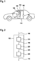
- Fig. 1 shows a schematic representation of a vehicle 100 with a device 102 according to one embodiment.
- the device 102 is used to determine a duration of a critical state of a driver 104 of the vehicle 100.
- the device 102 is connected to a sensor device 106, here a camera for observing a face of the driver 104.
- the sensor device 106 is designed to transmit a state signal 108 representing a state of the driver 104 to the device 102.
- the state is about an opened or closed state of the eyes of the driver 104.
- the device 102 is configured to determine the duration of the critical state, such as the closed state of the eyes, using the state signal 108.
- the device 102 cumulates the duration of the critical state by means of a counter when the state signal 108 represents the critical state.
- the status signal 108 represents one non-critical condition of the driver, such as the open condition of the eyes, the device 102 initially keeps the duration of the critical condition constant. Only when the duration of the non-critical state exceeds a predetermined reference holding time t h , the device 102 resets the counter.
- the device 102 is designed to output, depending on the duration of the critical state, a warning signal 110, here an acoustic warning signal, by means of which the driver 104 can be warned of the critical state.
- a warning signal 110 here an acoustic warning signal
- Fig. 2 shows a schematic representation of a device 102 according to an embodiment, such as a device, as described above with reference to Fig. 1 is described.
- the device 102 comprises a read-in unit 210 for reading in the state signal 108.
- the device 102 comprises a counter unit 220, in short counter, which is designed to receive the state signal 108 from the read-in unit 210 and, using the state signal 108, a duration of the critical one Output state representing counter value 225.
- the counter unit 220 is designed to first check whether the status signal 108 represents the critical state or the non-critical state of the driver. As long as the state signal 108 represents the critical state, the counting sub-unit 220 increments the counter value 225.
- the counter value 225 thus represents a cumulative duration of the critical state. As soon as the check of the state signal 108 shows that the state signal 108 represents the non-critical state, the increase by the counter unit 220 is stopped and the counter value 225 is kept constant. If the duration of the non-critical state exceeds the reference holding time t h , the counter unit 220 sets the counter value 225 to a lower value, for example to zero.
- counter value 225 may be incrementally increased intermittently until during a phase of the non-critical state indicating state signal 108, the reference hold time t h is exceeded.
- the device 102 comprises an output unit 230 which is configured to receive the counter value 225 from the counter unit 220 and to compare it with a limit value representing, for example, a second-sleep of the driver. If the comparison reveals that the counter value 225 exceeds the limit value, the output unit 230 outputs the warning signal 110 for warning the driver.
- a limit value representing, for example, a second-sleep of the driver.
- FIG. 12 shows a flowchart of a method 300 according to one embodiment.
- the method 300 may be used in conjunction with a device as described above with reference to FIG Figures 1 and 2 is described. Shown is an exemplary sequence of a calculation rule for determining the duration of the critical state.
- the status signal is read in in a step 305. Subsequently, it is checked in a step 310 whether the state signal represents the critical state, also called event, or the non-critical state. In the event of an event, in step 320, the counter value of the counter is incremented, and in response to the incrementing in step 310, the status signal is rechecked. Otherwise, in a step 330, the counter value is kept constant.
- a since a last event elapsed hold time is determined, for example, t e, wherein the counter value during the holding time t e is kept constant.
- the holding time t e to the reference holding time t h as compared to a deviation between the holding time t e and the reference holding time t to determine h. If it is found here that the holding time t e is greater than the reference holding time t h , the counter is reset or reduced in a step 350. In response to the reset or decrease, step 310 is performed again. On the other hand, if it is found that the hold time t e is smaller than the reference hold time t h , step 310 is repeated directly without resetting or decreasing the counter.
- the individual steps of the method 300 can be carried out continuously.
- Fig. 4 shows a diagram for exemplifying a cumulative duration of a critical state.
- the duration of the critical state can be determined, for example, by using a device as described above with reference to FIG FIGS. 1 and 3 described, be cumulative.
- Shown is a curve representing the counter value 225. Below the curve of the counter value 225, a profile of the state signal 108 is drawn in, which has the characteristic of a rectangular signal here by way of example.
- the counter value 225 is equal to zero.
- the state signal 108 rises abruptly to a value that represents the critical state, in this case the closed state of the eyes. In this case, the counter value 225 begins to increase substantially linearly.
- the state signal 108 drops abruptly to zero and remains at zero for a duration shorter than the reference hold time t h .
- the counter value 225 remains constant.
- the state signal 108 in turn jumps to the value representing the critical state, so that the counter value 225 in turn increases substantially linearly, starting from a value determined last.
- the counter value 225 exceeds a threshold value x, previously also called limit value, which leads to the generation of a microsleep signal 400.
- a profile of the microsleep signal 400 here likewise a square-wave signal, is shown below the course of the state signal 108.
- the counter value 225 continues to increase following the exceeding of the threshold value x, until the state signal 108 finally drops again to zero, so that the meanwhile increased counter value 225 remains constant.
- the holding time t e exceeds the reference holding time t h , which leads to the reset of the counter. Accordingly, the counter value 225 abruptly drops to zero. Thus, the second sleep signal 400 is no longer available.
- step 310 the recognition of the critical state "eyes closed". Subsequently, the duration of the critical state is calculated. This calculates the time duration for which the condition "eyes closed” exists. This is done by means of a counter which accumulates the time as long as the eyes are classified as closed in the previous step.
- the counter is reset to zero and begins again the next time the eyes are closed.
- the value of the counter then represents the accumulated duration of the closed eye state.
- a hysteresis is now built in, which is able to bridge short oscillations of the state signal 108 without the counter being reset to zero each time.
- This has the advantage that in a driver who only briefly opens his eyes and then closes again, a microsleep earlier can be detected.
- inadequacies of the input signals can be bridged, so that microsleep can be detected even with short-term failing input signals.
- the in Fig. 3 shown calculation rule used.
- the counter is increased according to the existence of the critical state, also called event, according to the time duration since a last test. If this calculation rule is carried out in a constant and determinate cycle time, the duration between the cycles for incrementing the counter is used here.
- This method has the advantage that only one memory element, namely the counter, is required to calculate the duration of the critical state. This allows the duration to be calculated very efficiently.
- the reference holding time t h is now introduced to make the calculation robust against short-term sensor errors.
- the state of the counter is held in the absence of the critical state for a certain time. Only after the reference holding time t h has elapsed is the counter reset or decremented. The result of such a calculation is in Fig. 4 shown.
- the issuing of a warning decision essentially follows the principle that is warned as soon as the threshold value x is exceeded in the accumulated duration of the critical state. For example, a warning is issued when the duration of the critical state reaches 1 s.
- the threshold value x is variable, for example, and is selected depending on external parameters.
- an exemplary embodiment comprises a "and / or" link between a first feature and a second feature, then this is to be read so that the embodiment according to one embodiment, both the first feature and the second feature and according to another embodiment either only first feature or only the second feature.
Landscapes
- Health & Medical Sciences (AREA)
- Life Sciences & Earth Sciences (AREA)
- Engineering & Computer Science (AREA)
- Medical Informatics (AREA)
- Public Health (AREA)
- Physics & Mathematics (AREA)
- General Health & Medical Sciences (AREA)
- Pathology (AREA)
- Biomedical Technology (AREA)
- Molecular Biology (AREA)
- Veterinary Medicine (AREA)
- Animal Behavior & Ethology (AREA)
- Surgery (AREA)
- Biophysics (AREA)
- Heart & Thoracic Surgery (AREA)
- Psychiatry (AREA)
- Physiology (AREA)
- Social Psychology (AREA)
- Child & Adolescent Psychology (AREA)
- Developmental Disabilities (AREA)
- Educational Technology (AREA)
- Hospice & Palliative Care (AREA)
- Psychology (AREA)
- Signal Processing (AREA)
- Artificial Intelligence (AREA)
- Computer Vision & Pattern Recognition (AREA)
- Mechanical Engineering (AREA)
- Transportation (AREA)
- Dentistry (AREA)
- Oral & Maxillofacial Surgery (AREA)
- Primary Health Care (AREA)
- Epidemiology (AREA)
- Databases & Information Systems (AREA)
- Data Mining & Analysis (AREA)
- Chemical & Material Sciences (AREA)
- Combustion & Propulsion (AREA)
- Automation & Control Theory (AREA)
- Mathematical Physics (AREA)
- Traffic Control Systems (AREA)
- Emergency Alarm Devices (AREA)
Abstract
Description
- Die Erfindung geht aus von einer Vorrichtung oder einem Verfahren nach Gattung der unabhängigen Ansprüche. Gegenstand der vorliegenden Erfindung ist auch ein Computerprogramm.
- Ein Fahrzeug kann mit einem Warnsystem zum Warnen eines Fahrers vor Müdigkeit oder Sekundenschlaf ausgestattet sein.
- Vor diesem Hintergrund werden mit dem hier vorgestellten Ansatz ein Verfahren zum Bestimmen einer Dauer eines kritischen Zustands eines Fahrers eines Fahrzeugs, weiterhin eine Vorrichtung, die dieses Verfahren verwendet, sowie schließlich ein entsprechendes Computerprogramm gemäß den Hauptansprüchen vorgestellt. Durch die in den abhängigen Ansprüchen aufgeführten Maßnahmen sind vorteilhafte Weiterbildungen und Verbesserungen der im unabhängigen Anspruch angegebenen Vorrichtung möglich.
- Es wird ein Verfahren zum Bestimmen einer Dauer eines kritischen Zustands eines Fahrers eines Fahrzeugs vorgestellt, wobei das Verfahren folgende Schritte umfasst:
- Einlesen eines Zustandssignals, das einen unter Verwendung einer Sensoreinrichtung des Fahrzeugs erfassten Zustand des Fahrers repräsentiert; Überprüfen, ob das Zustandssignal den kritischen Zustand oder einen nicht kritischen Zustand des Fahrers repräsentiert;
- Erhöhen eines die Dauer des kritischen Zustands repräsentierenden Zählerwerts eines Zählers, wenn das Zustandssignal den kritischen Zustand repräsentiert;
- Konstanthalten des Zählerwerts, wenn das Zustandssignal den nicht kritischen Zustand repräsentiert; und
- Verringern des Zählerwerts, wenn das Zustandssignal nach Ablauf einer Referenzhaltezeit den nicht kritischen Zustand repräsentiert.
- Unter einem kritischen Zustand kann ein Zustand des Fahrers verstanden werden, durch den eine Fahrtüchtigkeit des Fahrers beeinträchtigt ist. Insbesondere kann es sich bei dem kritischen Zustand beispielsweise um einen Zustand handeln, in dem die Augen des Fahrers für eine längere Dauer, etwa länger als die Dauer eines Lidschlags, geschlossen sind. Dementsprechend kann unter einem nicht kritischen Zustand ein Zustand des Fahrers verstanden werden, in dem die Fahrtüchtigkeit des Fahrers unbeeinträchtigt ist. Das Fahrzeug kann mit einer Sensoreinrichtung zum Überwachen des Fahrers ausgestattet sein. Die Sensoreinrichtung, beispielsweise eine Kamera oder ein Infrarotsensor, kann ausgebildet sein, um einen Kopfbereich des Fahrers, insbesondere eine Augenpartie des Fahrers, zu überwachen. Unter einem Zustandssignal kann ein unter Verwendung der Sensoreinrichtung erzeugtes Signal verstanden werden. Unter einem Zähler kann beispielsweise ein digitales Zählwerk oder ein Softwarezähler verstanden werden. Unter einer Referenzhaltezeit kann eine vorgegebene Höchstdauer verstanden werden, während der der Zählerwert konstant gehalten werden kann. Die Referenzhaltezeit kann beispielsweise zwischen 0,1 s und 0,5 s liegen.
- Der hier vorgestellte Ansatz beruht auf der Erkenntnis, dass ein Zähler zum Bestimmen einer kumulierten Dauer eines kritischen Zustands eines Fahrers verzögert zurückgesetzt werden kann. Dies hat den Vorteil, dass kurze Oszillationen eines den kritischen Zustand repräsentierenden Eingangssignals überbrückt werden können, ohne dass der Zähler jedes Mal zurückgesetzt wird. Somit kann bei einem Fahrer, der nur kurzzeitig die Augen öffnet und sie danach wieder schließt, frühzeitig ein Sekundenschlaf erkannt werden. Zudem können Unzulänglichkeiten des Eingangssignals überbrückt werden, sodass der Sekundenschlaf auch bei kurzzeitig ausfallendem Eingangssignal erkannt werden kann. Der hier vorgestellte Ansatz ermöglicht somit auch bei kurzzeitigen Sensorfehlern eine effiziente und robuste Erkennung der Dauer des kritischen Zustands.
- Gemäß einer Ausführungsform wird im Schritt des Überprüfens überprüft, ob das Zustandssignal einen geschlossenen Zustand der Augen des Fahrers als den kritischen Zustand repräsentiert oder einen geöffneten Zustand der Augen als den nicht kritischen Zustand repräsentiert. Dadurch kann überprüft werden, ob der Fahrer mit geöffneten oder geschlossenen Augen fährt.
- Gemäß einer weiteren Ausführungsform kann im Schritt des Erhöhens der Zählerwert weiter erhöht werden, wenn sich beim Überprüfen ergibt, dass das Zustandssignal nachfolgend auf das Konstanthalten oder, zusätzlich oder alternativ, nachfolgend auf das Verringern erneut den kritischen Zustand repräsentiert. Dadurch kann die Dauer des kritischen Zustands kumuliert werden.
- Es ist ferner vorteilhaft, wenn im Schritt des Erhöhens der Zählerwert im Wesentlichen linear erhöht wird. Dadurch kann die Dauer des kritischen Zustands mit geringem Rechenaufwand ermittelt werden.
- Das Verfahren kann zudem einen Schritt des Ermittelns einer Haltezeit, während der der Zählerwert konstant gehalten wird, umfassen. In einem Schritt des Vergleichens können die Haltezeit und die Referenzhaltezeit miteinander verglichen werden, um eine Abweichung zwischen der Haltezeit und der Referenzhaltezeit zu ermitteln. Im Schritt des Verringerns kann der Zählerwert verringert werden, wenn sich beim Vergleichen ergibt, dass die Haltezeit größer als die Referenzhaltezeit ist. Entsprechend kann im Schritt des Überprüfens das Zustandssignal erneut überprüft werden, wenn sich beim Vergleichen ergibt, dass die Haltezeit kleiner als die Referenzhaltezeit ist. Durch diese Ausführungsform kann die Dauer des kritischen Zustands schnell und mit geringem Speicherbedarf ermittelt werden.
- Von Vorteil ist ferner, wenn in einem Schritt des Bestimmens eine Abweichung zwischen dem Zählerwert und einem Grenzwert bestimmt wird. Hierbei kann in einem Schritt des Ausgebens abhängig von der Abweichung zwischen dem Zählerwert und dem Grenzwert ein Warnsignal zum Warnen des Fahrers ausgegeben werden. Unter einem Grenzwert kann beispielsweise ein einen Sekundenschlaf repräsentierender Schwellenwert verstanden werden. Durch diese Ausführungsform kann der Fahrer frühzeitig vor dem kritischen Zustand gewarnt werden.
- Gemäß einer weiteren Ausführungsform kann im Schritt des Verringerns der Zählerwert auf null gesetzt werden. Dadurch kann der Zähler einfach zurückgesetzt werden.
- Dieses Verfahren kann beispielsweise in Software oder Hardware oder in einer Mischform aus Software und Hardware, beispielsweise in einem Steuergerät, implementiert sein.
- Der hier vorgestellte Ansatz schafft ferner eine Vorrichtung, die ausgebildet ist, um die Schritte einer Variante eines hier vorgestellten Verfahrens in entsprechenden Einrichtungen durchzuführen, anzusteuern bzw. umzusetzen. Auch durch diese Ausführungsvariante der Erfindung in Form einer Vorrichtung kann die der Erfindung zugrunde liegende Aufgabe schnell und effizient gelöst werden.
- Hierzu kann die Vorrichtung zumindest eine Recheneinheit zum Verarbeiten von Signalen oder Daten, zumindest eine Speichereinheit zum Speichern von Signalen oder Daten, zumindest eine Schnittstelle zu einem Sensor oder einem Aktor zum Einlesen von Sensorsignalen von dem Sensor oder zum Ausgeben von Daten- oder Steuersignalen an den Aktor und/oder zumindest eine Kommunikationsschnittstelle zum Einlesen oder Ausgeben von Daten aufweisen, die in ein Kommunikationsprotokoll eingebettet sind. Die Recheneinheit kann beispielsweise ein Signalprozessor, ein Mikrocontroller oder dergleichen sein, wobei die Speichereinheit ein Flash-Speicher, ein EPROM oder eine magnetische Speichereinheit sein kann. Die Kommunikationsschnittstelle kann ausgebildet sein, um Daten drahtlos und/oder leitungsgebunden einzulesen oder auszugeben, wobei eine Kommunikationsschnittstelle, die leitungsgebundene Daten einlesen oder ausgeben kann, diese Daten beispielsweise elektrisch oder optisch aus einer entsprechenden Datenübertragungsleitung einlesen oder in eine entsprechende Datenübertragungsleitung ausgeben kann.
- Unter einer Vorrichtung kann vorliegend ein elektrisches Gerät verstanden werden, das Sensorsignale verarbeitet und in Abhängigkeit davon Steuer- und/oder Datensignale ausgibt. Die Vorrichtung kann eine Schnittstelle aufweisen, die hard- und/oder softwaremäßig ausgebildet sein kann. Bei einer hardwaremäßigen Ausbildung können die Schnittstellen beispielsweise Teil eines sogenannten System-ASICs sein, der verschiedenste Funktionen der Vorrichtung beinhaltet. Es ist jedoch auch möglich, dass die Schnittstellen eigene, integrierte Schaltkreise sind oder zumindest teilweise aus diskreten Bauelementen bestehen. Bei einer softwaremäßigen Ausbildung können die Schnittstellen Softwaremodule sein, die beispielsweise auf einem Mikrocontroller neben anderen Softwaremodulen vorhanden sind.
- In einer vorteilhaften Ausgestaltung erfolgt durch die Vorrichtung eine Steuerung des Fahrzeugs. Hierzu kann die Vorrichtung beispielsweise auf Sensorsignale wie Beschleunigungs-, Druck-, Lenkwinkel- oder Umfeldsensorsignale zugreifen. Die Ansteuerung erfolgt über Aktoren wie Brems- oder Lenkaktoren oder ein Motorsteuergerät des Fahrzeugs.
- Von Vorteil ist auch ein Computerprogrammprodukt oder Computerprogramm mit Programmcode, der auf einem maschinenlesbaren Träger oder Speichermedium wie einem Halbleiterspeicher, einem Festplattenspeicher oder einem optischen Speicher gespeichert sein kann und zur Durchführung, Umsetzung und/oder Ansteuerung der Schritte des Verfahrens nach einer der vorstehend beschriebenen Ausführungsformen verwendet wird, insbesondere wenn das Programmprodukt oder Programm auf einem Computer oder einer Vorrichtung ausgeführt wird.
- Ausführungsbeispiele der Erfindung sind in den Zeichnungen dargestellt und in der nachfolgenden Beschreibung näher erläutert. Es zeigt:
-
Fig. 1 eine schematische Darstellung eines Fahrzeugs mit einer Vorrichtung gemäß einem Ausführungsbeispiel; -
Fig. 2 eine schematische Darstellung einer Vorrichtung gemäß einem Ausführungsbeispiel; -
Fig. 3 eine schematische Darstellung eines Verfahrens gemäß einem Ausführungsbeispiel; und -
Fig. 4 ein Diagramm zur exemplarischen Darstellung einer kumulierten Dauer eines kritischen Zustands. - In der nachfolgenden Beschreibung günstiger Ausführungsbeispiele der vorliegenden Erfindung werden für die in den verschiedenen Figuren dargestellten und ähnlich wirkenden Elemente gleiche oder ähnliche Bezugszeichen verwendet, wobei auf eine wiederholte Beschreibung dieser Elemente verzichtet wird.
-
Fig. 1 zeigt eine schematische Darstellung eines Fahrzeugs 100 mit einer Vorrichtung 102 gemäß einem Ausführungsbeispiel. Die Vorrichtung 102 dient zum Bestimmen einer Dauer eines kritischen Zustands eines Fahrers 104 des Fahrzeugs 100. Hierzu ist die Vorrichtung 102 mit einer Sensoreinrichtung 106, hier einer Kamera zum Beobachten eines Gesichts des Fahrers 104, verbunden. Gemäß diesem Ausführungsbeispiel ist die Sensoreinrichtung 106 ausgebildet, um ein einen Zustand des Fahrers 104 repräsentierendes Zustandssignal 108 an die Vorrichtung 102 zu übertragen. Bei dem Zustand handelt es sich etwa um einen geöffneten oder geschlossenen Zustand der Augen des Fahrers 104. Die Vorrichtung 102 ist ausgebildet, um die Dauer des kritischen Zustands, etwa des geschlossenen Zustands der Augen, unter Verwendung des Zustandssignals 108 zu ermitteln. Hierbei kumuliert die Vorrichtung 102 die Dauer des kritischen Zustands mittels eines Zählers, wenn das Zustandssignal 108 den kritischen Zustand repräsentiert. Repräsentiert das Zustandssignal 108 hingegen einen nicht kritischen Zustand des Fahrers, etwa den geöffneten Zustand der Augen, so hält die Vorrichtung 102 die Dauer des kritischen Zustands zunächst konstant. Erst wenn die Dauer des nicht kritischen Zustands eine vorgegebene Referenzhaltezeit th überschreitet, setzt die Vorrichtung 102 den Zähler zurück. - Gemäß dem in
Fig. 1 gezeigten Ausführungsbeispiel ist die Vorrichtung 102 ausgebildet, um je nach Dauer des kritischen Zustands ein Warnsignal 110, hier ein akustisches Warnsignal, auszugeben, durch das der Fahrer 104 vor dem kritischen Zustand gewarnt werden kann. -
Fig. 2 zeigt eine schematische Darstellung einer Vorrichtung 102 gemäß einem Ausführungsbeispiel, etwa einer Vorrichtung, wie sie vorangehend anhand vonFig. 1 beschrieben ist. Die Vorrichtung 102 umfasst eine Einleseeinheit 210 zum Einlesen des Zustandssignals 108. Ferner umfasst die Vorrichtung 102 eine Zählereinheit 220, kurz Zähler, die ausgebildet ist, um das Zustandssignal 108 von der Einleseeinheit 210 zu empfangen und unter Verwendung des Zustandssignals 108 einen die Dauer des kritischen Zustands repräsentierenden Zählerwert 225 auszugeben. Hierbei ist die Zählereinheit 220 ausgebildet, um zunächst zu überprüfen, ob das Zustandssignal 108 den kritischen Zustand oder den nicht kritischen Zustand des Fahrers repräsentiert. Solange das Zustandssignal 108 den kritischen Zustand repräsentiert, erhöht die Zähluntereinheit 220 den Zählerwert 225. Der Zählerwert 225 repräsentiert somit eine kumulierte Dauer des kritischen Zustands. Sobald die Überprüfung des Zustandssignals 108 ergibt, dass das Zustandssignal 108 den nicht kritischen Zustand repräsentiert, wird die Erhöhung durch die Zählereinheit 220 gestoppt und der Zählerwert 225 konstant gehalten. Überschreitet die Dauer des nicht kritischen Zustands die Referenzhaltezeit th, so setzt die Zählereinheit 220 den Zählerwert 225 auf einen niedrigeren Wert, beispielsweise auf null. - Wenn die Überprüfung des Zustandssignals 108 ergibt, dass das Zustandssignal 108 vor Ablauf der Referenzhaltezeit th wieder den kritischen Zustand repräsentiert, wo wird die Erhöhung des konstant gehaltenen Zählerwerts 225 durch die Zählereinheit 220 fortgesetzt, beispielsweise bis die Überprüfung des Zustandssignals 108 ergibt, dass das Zustandssignal 108 wieder den nicht kritischen Zustand repräsentiert. Somit kann der Zählerwert 225 mit Unterbrechungen immer weiter erhöht werden, bis während einer Phase des den nicht kritischen Zustand anzeigenden Zustandssignal 108 die Referenzhaltezeit th überschritten wird.
- Gemäß einem optionalen Ausführungsbeispiel umfasst die Vorrichtung 102 eine Ausgabeeinheit 230, die ausgebildet ist, um den Zählerwert 225 von der Zählereinheit 220 zu empfangen und diesen mit einem Grenzwert, der beispielsweise einen Sekundenschlaf des Fahrers repräsentiert, zu vergleichen. Ergibt der Vergleich, dass der Zählerwert 225 den Grenzwert überschreitet, so gibt die Ausgabeeinheit 230 das Warnsignal 110 zum Warnen des Fahrers aus.
-
Fig. 3 zeigt ein Ablaufdiagramm eines Verfahrens 300 gemäß einem Ausführungsbeispiel. Das Verfahren 300 kann im Zusammenhang mit einer Vorrichtung, wie sie vorangehend anhand derFiguren 1 und 2 beschrieben ist, durchgeführt werden. Gezeigt ist ein beispielhafter Ablauf einer Rechenvorschrift zur Bestimmung der Dauer des kritischen Zustands. Hierbei wird in einem Schritt 305 das Zustandssignal eingelesen. Anschließend wird in einem Schritt 310 überprüft, ob das Zustandssignal den kritischen Zustand, auch Ereignis genannt, oder den nicht kritischen Zustand repräsentiert. Im Fall eines Ereignisses wird in einem Schritt 320 der Zählerwert des Zählers erhöht, wobei ansprechend auf das Erhöhen im Schritt 310 das Zustandssignal erneut überprüft wird. Andernfalls wird in einem Schritt 330 der Zählerwert konstant gehalten. Hierbei wird beispielsweise eine seit einem letzten Ereignis vergangene Haltezeit te ermittelt, wobei der Zählerwert während der Haltezeit te konstant gehalten wird. In einem Schritt 340 wird die Haltezeit te mit der Referenzhaltezeit th verglichen, um eine Abweichung zwischen der Haltezeit te und der Referenzhaltezeit th zu ermitteln. Ergibt sich hierbei, dass die Haltezeit te größer als die Referenzhaltezeit th ist, so wird in einem Schritt 350 der Zähler zurückgesetzt oder verringert. Ansprechend auf das Zurücksetzen oder Verringern wird der Schritt 310 erneut durchgeführt. Ergibt sich hingegen, dass die Haltezeit te kleiner als die Referenzhaltezeit th ist, so wird der Schritt 310 ohne Zurücksetzen oder Verringern des Zählers direkt wiederholt. - Die einzelnen Schritte des Verfahrens 300 können fortlaufend durchgeführt werden.
-
Fig. 4 zeigt ein Diagramm zur exemplarischen Darstellung einer kumulierten Dauer eines kritischen Zustands. Die Dauer des kritischen Zustands kann beispielsweise unter Verwendung einer Vorrichtung, wie sie vorangehend anhand derFiguren 1 und3 beschrieben ist, kumuliert sein. Gezeigt ist eine den Zählerwert 225 repräsentierende Kurve. Unterhalb der Kurve des Zählerwerts 225 ist ein Verlauf des Zustandssignals 108 eingezeichnet, das hier beispielhaft den Verlauf eines Rechtecksignals aufweist. Zu Beginn der Berechnung ist der Zählerwert 225 gleich null. Nach einer kurzen Zeit steigt das Zustandssignal 108 sprungartig auf einen Wert an, der den kritischen Zustand, hier also den geschlossenen Zustand der Augen, repräsentiert. Dabei beginnt der Zählerwert 225 im Wesentlichen linear anzusteigen. Anschließend fällt das Zustandssignal 108 sprungartig auf null ab und bleibt für eine Dauer, die kürzer als die Referenzhaltezeit th ist, auf null. Während dieser Dauer, vorangehend auch Haltezeit te genannt, bleibt der Zählerwert 225 konstant. Anschließend steigt das Zustandssignal 108 wiederum sprungartig auf den den kritischen Zustand repräsentierenden Wert an, sodass sich der Zählerwert 225 wiederum, ausgehend von einem zuletzt ermittelten Wert, im Wesentlichen linear erhöht. Hierbei überschreitet der Zählerwert 225 einen Schwellenwert x, vorangehend auch Grenzwert genannt, was zur Generierung eines Sekundenschlafsignals 400 führt. Ein Verlauf des Sekundenschlafsignals 400, hier ebenfalls ein Rechtecksignal, ist unterhalb des Verlaufs des Zustandssignals 108 eingezeichnet. Der Zählerwert 225 steigt nachfolgend auf das Überschreiten des Schwellenwertes x weiter an, bis das Zustandssignal 108 schließlich wiederum auf null abfällt, sodass der zwischenzeitlich erhöhte Zählerwert 225 konstant bleibt. Die Haltezeit te überschreitet hierbei die Referenzhaltezeit th, was zum Zurücksetzen des Zählers führt. Dementsprechend fällt der Zählerwert 225 sprungartig auf null ab. Somit liegt auch das Sekundenschlafsignal 400 nicht mehr an. - Nachfolgend wird der hier vorgestellte Ansatz anhand der
Figuren 1 bis 4 nochmals mit anderen Worten zusammengefasst. - Zunächst erfolgt im Schritt 310 die Erkennung des kritischen Zustands "Augen geschlossen". Anschließend erfolgt die Berechnung der Dauer des kritischen Zustands. Hierbei wird die Zeitdauer berechnet, für die der Zustand "Augen geschlossen" vorliegt. Dies erfolgt mittels eines Zählers, der die Zeit so lange kumuliert, wie die Augen im vorherigen Schritt als geschlossen klassifiziert werden.
- Sobald die Augen im Schritt 310 wieder als offen klassifiziert werden, wird der Zähler auf null gesetzt und beginnt beim nächsten Schließen der Augen erneut. Der Wert des Zählers repräsentiert dann die kumulierte Dauer des Zustands "geschlossene Augen".
- Hierbei wird nun eine Hysterese eingebaut, die in der Lage ist, kurze Oszillationen des Zustandssignals 108 zu überbrücken, ohne dass der Zähler jedes Mal wieder auf null gesetzt wird. Dies hat den Vorteil, dass bei einem Fahrer, der nur kurzzeitig seine Augen öffnet und sie danach wieder schließt, frühzeitiger ein Sekundenschlaf erkannt werden kann. Zudem können so Unzulänglichkeiten der Eingangssignale überbrückt werden, sodass Sekundenschlaf auch bei kurzzeitig ausfallenden Eingangssignalen erkannt werden kann.
- Zur effizienten Berechnung der Dauer des kritischen Zustands wird beispielsweise die in
Fig. 3 gezeigte Rechenvorschrift verwendet. Dabei wird der Zähler je nach Vorhandensein des kritischen Zustands, auch Ereignis genannt, entsprechend der zeitlichen Dauer seit einer letzten Prüfung erhöht. Wird diese Rechenvorschrift in einer konstanten und determinierten Zykluszeit durchgeführt, wird hier die Dauer zwischen den Zyklen zum Inkrementieren des Zählers verwendet. Diese Methode hat den Vorteil, dass zur Berechnung der Dauer des kritischen Zustands lediglich ein Speicherelement, nämlich der Zähler, erforderlich ist. Dadurch kann die Dauer sehr effizient berechnet werden. - Es kann passieren, dass der kritische Zustand für kurze Zeiten nicht erkannt wird. Stattdessen kann fälschlicherweise der nicht kritische Zustand, bei dem die Augen geöffnet sind, erkannt werden oder es ist gar keine Erkennung möglich. In diesen Fällen würde der Zähler fälschlicherweise wieder auf null gesetzt, was eine Erkennung längerer kritischer Zustände, etwa eines Sekundenschlafs, unmöglich macht. Zur Lösung dieses Problems wird nun die Referenzhaltezeit th eingeführt, um die Berechnung robust gegenüber kurzzeitigen Sensorfehlern zu machen. Dabei wird der Zustand des Zählers bei Nichtvorhandensein des kritischen Zustands für eine gewisse Zeit gehalten. Erst nach Ablauf der Referenzhaltezeit th wird der Zähler zurückgesetzt oder dekrementiert. Das Ergebnis einer solchen Berechnung ist in
Fig. 4 dargestellt. Der Wertebereich der Referenzhaltezeit th wird abhängig von der gegebenen Leistung der Sensoreinrichtung 106 und der erkennenden Dauer der kritischen Zustände gewählt. Es kann beispielsweise th = 0,2 s gesetzt werden. - Die Ausgabe einer Warnentscheidung erfolgt im Wesentlichen nach dem Prinzip, dass gewarnt wird, sobald der Schwellenwert x in der kumulierten Dauer des kritischen Zustands überschritten wird. Beispielsweise erfolgt eine Warnung, wenn die Dauer des kritischen Zustands 1 s erreicht. Der Schwellenwert x ist beispielsweise variabel und wird abhängig von externen Parametern gewählt.
- Umfasst ein Ausführungsbeispiel eine "und/oder"-Verknüpfung zwischen einem ersten Merkmal und einem zweiten Merkmal, so ist dies so zu lesen, dass das Ausführungsbeispiel gemäß einer Ausführungsform sowohl das erste Merkmal als auch das zweite Merkmal und gemäß einer weiteren Ausführungsform entweder nur das erste Merkmal oder nur das zweite Merkmal aufweist.
Claims (10)
- Verfahren (300) zum Bestimmen einer Dauer eines kritischen Zustands eines Fahrers (104) eines Fahrzeugs (100), wobei das Verfahren (300) folgende Schritte umfasst:Einlesen (305) eines Zustandssignals (108), das einen unter Verwendung einer Sensoreinrichtung (106) des Fahrzeugs (100) erfassten Zustand des Fahrers (104) repräsentiert;Überprüfen (310), ob das Zustandssignal (108) den kritischen Zustand oder einen nicht kritischen Zustand des Fahrers (104) repräsentiert;Erhöhen (320) eines die Dauer des kritischen Zustands repräsentierenden Zählerwerts (225) eines Zählers, wenn das Zustandssignal (108) den kritischen Zustand repräsentiert;Konstanthalten (330) des Zählerwerts (225), wenn das Zustandssignal (108) den nicht kritischen Zustand repräsentiert; undVerringern (350) des Zählerwerts (225), wenn das Zustandssignal (108) nach Ablauf einer Referenzhaltezeit (th) den nicht kritischen Zustand repräsentiert.
- Verfahren (300) gemäß Anspruch 1, bei dem im Schritt des Überprüfens (310) überprüft wird, ob das Zustandssignal (108) einen geschlossenen Zustand der Augen des Fahrers (104) als den kritischen Zustand repräsentiert oder einen geöffneten Zustand der Augen als den nicht kritischen Zustand repräsentiert.
- Verfahren (300) gemäß einem der vorangegangenen Ansprüche, bei dem im Schritt des Erhöhens (320) der Zählerwert (225) weiter erhöht wird, wenn sich beim Überprüfen (310) ergibt, dass das Zustandssignal (108) nachfolgend auf das Konstanthalten (330) und/oder das Verringern (350) erneut den kritischen Zustand repräsentiert.
- Verfahren (300) gemäß einem der vorangegangenen Ansprüche, bei dem im Schritt des Erhöhens (320) der Zählerwert (225) im Wesentlichen linear erhöht wird.
- Verfahren (300) gemäß einem der vorangegangenen Ansprüche, mit einem Schritt des Ermittelns einer Haltezeit (te), während der der Zählerwert (225) konstant gehalten wird, wobei in einem Schritt des Vergleichens (340) die Haltezeit (te) und die Referenzhaltezeit (th) miteinander verglichen werden, um eine Abweichung zwischen der Haltezeit (te) und der Referenzhaltezeit (th) zu ermitteln, wobei im Schritt des Verringerns (350) der Zählerwert (225) verringert wird, wenn sich beim Vergleichen (340) ergibt, dass die Haltezeit (te) größer als die Referenzhaltezeit (th) ist, wobei im Schritt des Überprüfens (310) das Zustandssignal (108) erneut überprüft wird, wenn sich beim Vergleichen (340) ergibt, dass die Haltezeit (te) kleiner als die Referenzhaltezeit (th) ist.
- Verfahren (300) gemäß einem der vorangegangenen Ansprüche, mit einem Schritt des Bestimmens einer Abweichung zwischen dem Zählerwert (225) und einem Grenzwert (x), wobei in einem Schritt des Ausgebens abhängig von der Abweichung zwischen dem Zählerwert (225) und dem Grenzwert (x) ein Warnsignal (110) zum Warnen des Fahrers (104) ausgegeben wird.
- Verfahren (300) gemäß einem der vorangegangenen Ansprüche, bei dem im Schritt des Verringerns (350) der Zählerwert (225) auf null gesetzt wird.
- Vorrichtung (102) mit Einheiten (210, 220, 230), die ausgebildet sind, um das Verfahren (300) gemäß einem der vorangegangenen Ansprüche auszuführen und/oder anzusteuern.
- Computerprogramm, das ausgebildet ist, um das Verfahren (300) gemäß einem der Ansprüche 1 bis 7 auszuführen und/oder anzusteuern.
- Maschinenlesbares Speichermedium, auf dem das Computerprogramm nach Anspruch 9 gespeichert ist.
Applications Claiming Priority (1)
| Application Number | Priority Date | Filing Date | Title |
|---|---|---|---|
| DE102016213671.2A DE102016213671A1 (de) | 2016-07-26 | 2016-07-26 | Verfahren und Vorrichtung zum Bestimmen einer Dauer eines kritischen Zustands eines Fahrers eines Fahrzeugs |
Publications (3)
| Publication Number | Publication Date |
|---|---|
| EP3275370A2 true EP3275370A2 (de) | 2018-01-31 |
| EP3275370A3 EP3275370A3 (de) | 2018-04-18 |
| EP3275370B1 EP3275370B1 (de) | 2024-02-28 |
Family
ID=58638724
Family Applications (1)
| Application Number | Title | Priority Date | Filing Date |
|---|---|---|---|
| EP17168274.3A Active EP3275370B1 (de) | 2016-07-26 | 2017-04-26 | Verfahren und vorrichtung zum bestimmen einer dauer eines kritischen zustands eines fahrers eines fahrzeugs |
Country Status (4)
| Country | Link |
|---|---|
| US (1) | US10105104B2 (de) |
| EP (1) | EP3275370B1 (de) |
| CN (1) | CN107650913B (de) |
| DE (1) | DE102016213671A1 (de) |
Family Cites Families (10)
| Publication number | Priority date | Publication date | Assignee | Title |
|---|---|---|---|---|
| JP3183161B2 (ja) * | 1996-04-12 | 2001-07-03 | 三菱自動車工業株式会社 | 覚醒度推定装置 |
| DE19803158C1 (de) * | 1998-01-28 | 1999-05-06 | Daimler Chrysler Ag | Vorrichtung zur Vigilanzzustandsbestimmung |
| US5900819A (en) * | 1998-04-21 | 1999-05-04 | Meritor Heavy Vehicle Systems, Llc | Drowsy driver detection system |
| JP4274225B2 (ja) * | 2006-10-13 | 2009-06-03 | トヨタ自動車株式会社 | 車載警告装置 |
| DE102006051922A1 (de) * | 2006-11-03 | 2008-05-08 | Robert Bosch Gmbh | Fahrerinformations- und -dialogsystem |
| JP4492652B2 (ja) * | 2007-07-26 | 2010-06-30 | トヨタ自動車株式会社 | 眠気状態判断装置 |
| DE102008056343B4 (de) * | 2008-11-07 | 2024-07-25 | Bayerische Motoren Werke Aktiengesellschaft | Warnsystem für ein Kraftfahrzeug |
| CN101599207A (zh) * | 2009-05-06 | 2009-12-09 | 深圳市汉华安道科技有限责任公司 | 一种疲劳驾驶检测装置及汽车 |
| MX2017002988A (es) * | 2014-09-09 | 2018-02-01 | Torvec Inc | Métodos y aparato para monitorear el nivel de alerta de una persona que utiliza un dispositivo portátil, y proporcionar una notificación. |
| US9290174B1 (en) * | 2014-10-23 | 2016-03-22 | GM Global Technology Operations LLC | Method and system for mitigating the effects of an impaired driver |
-
2016
- 2016-07-26 DE DE102016213671.2A patent/DE102016213671A1/de active Pending
-
2017
- 2017-04-26 EP EP17168274.3A patent/EP3275370B1/de active Active
- 2017-07-12 US US15/647,740 patent/US10105104B2/en active Active
- 2017-07-25 CN CN201710613121.7A patent/CN107650913B/zh active Active
Non-Patent Citations (1)
| Title |
|---|
| None |
Also Published As
| Publication number | Publication date |
|---|---|
| US20180028120A1 (en) | 2018-02-01 |
| CN107650913B (zh) | 2022-03-29 |
| DE102016213671A1 (de) | 2018-02-01 |
| EP3275370B1 (de) | 2024-02-28 |
| CN107650913A (zh) | 2018-02-02 |
| EP3275370A3 (de) | 2018-04-18 |
| US10105104B2 (en) | 2018-10-23 |
Similar Documents
| Publication | Publication Date | Title |
|---|---|---|
| EP3529679B1 (de) | Verfahren und vorrichtung zum unterstützen eines fahrers beim deaktivieren eines hochautomatisierten fahrmodus eines fahrzeugs | |
| DE102014205180B4 (de) | Verfahren und Vorrichtung zum Betreiben eines Fahrzeugs | |
| DE102016118100B4 (de) | Fahrunterstützungsvorrichtung für ein fahrzeug | |
| DE102015103570B4 (de) | Fahreranomalieerkennung | |
| DE102019204892A1 (de) | Verfahren und Steuergerät zum Erkennen einer Müdigkeit eines Fahrers für ein Fahrassistenzsystem für ein Fahrzeug | |
| DE112015005996T5 (de) | Fahrzeugdatenfernsammelsystem | |
| DE102011080257A1 (de) | System und Verfahren zur Gesichtserkennung | |
| DE112018005858T5 (de) | Elektronische steuervorrichtung | |
| DE102016215291A1 (de) | Verfahren zur Klassifikation von Fahrerbewegungen | |
| DE102015203793A1 (de) | Fahrermüdigkeitserkennung | |
| DE102016108475A1 (de) | Einschlaferfassungsvorrichtung | |
| DE102010002680A1 (de) | Verfahren und Vorrichtung zur Erkennung einer Abweichung eines Drehratensignals eines Drehratensensors | |
| EP3310248B1 (de) | Verfahren und vorrichtung zum unterscheiden von blinzelereignissen und instrumentenblicken unter verwendung einer augenöffnungsweite | |
| EP3275370B1 (de) | Verfahren und vorrichtung zum bestimmen einer dauer eines kritischen zustands eines fahrers eines fahrzeugs | |
| DE102007055639A1 (de) | Vorrichtung zur Ermittlung eines aktuellen Fahrzeugzustands | |
| DE102017202998A1 (de) | Verfahren und Steuergerät zum Steuern mindestens einer Assistenzfunktion für den Fall eines Überschlags eines Fahrzeugs und Assistenzsystem | |
| DE112019007052B4 (de) | Wachsamkeitsgrad-Einschätzungsvorrichtung, Vorrichtung zur Unterstützung eines automatischen Fahrens und Wachsamkeits-Einschätzungsverfahren | |
| EP2093093A2 (de) | Verfahren und Vorrichtung zur Erkennung fehlender Fahreraktivität am Lenkrad | |
| DE102016109821A1 (de) | Vorrichtung und Verfahren zur Fehlerüberwachung des Ruders eines Wasserfahrzeuges | |
| EP4168999A1 (de) | Verfahren zur unterstützung eines betriebs eines fahrzeuges mit einer sensoreinheit, computerprogrammprodukt sowie system | |
| DE102009040044A1 (de) | Verfahren zur Plausibilisierung von Modellparametern | |
| DE102024117877B3 (de) | Verfahren zur Ermittlung wenigstens einer Wahrnehmungsanforderung an eine Funktion eines Fahrzeugsystems eines Kraftfahrzeugs, Recheneinrichtung und Computerprogramm | |
| DE102014200426A1 (de) | Verfahren zur robusten Erkennung von hochfrequenten Signalstörungen | |
| DE102015221951A1 (de) | Verfahren zur Überprüfung einer Überwachungsfunktion | |
| DE102016209900B4 (de) | Verfahren und Vorrichtung zum Erkennen eines seitlichen Kippens eines Fahrzeugs und Fahrzeug |
Legal Events
| Date | Code | Title | Description |
|---|---|---|---|
| PUAI | Public reference made under article 153(3) epc to a published international application that has entered the european phase |
Free format text: ORIGINAL CODE: 0009012 |
|
| STAA | Information on the status of an ep patent application or granted ep patent |
Free format text: STATUS: THE APPLICATION HAS BEEN PUBLISHED |
|
| AK | Designated contracting states |
Kind code of ref document: A2 Designated state(s): AL AT BE BG CH CY CZ DE DK EE ES FI FR GB GR HR HU IE IS IT LI LT LU LV MC MK MT NL NO PL PT RO RS SE SI SK SM TR |
|
| AX | Request for extension of the european patent |
Extension state: BA ME |
|
| PUAL | Search report despatched |
Free format text: ORIGINAL CODE: 0009013 |
|
| AK | Designated contracting states |
Kind code of ref document: A3 Designated state(s): AL AT BE BG CH CY CZ DE DK EE ES FI FR GB GR HR HU IE IS IT LI LT LU LV MC MK MT NL NO PL PT RO RS SE SI SK SM TR |
|
| AX | Request for extension of the european patent |
Extension state: BA ME |
|
| RIC1 | Information provided on ipc code assigned before grant |
Ipc: A61B 5/18 20060101AFI20180314BHEP |
|
| STAA | Information on the status of an ep patent application or granted ep patent |
Free format text: STATUS: REQUEST FOR EXAMINATION WAS MADE |
|
| 17P | Request for examination filed |
Effective date: 20181018 |
|
| RBV | Designated contracting states (corrected) |
Designated state(s): AL AT BE BG CH CY CZ DE DK EE ES FI FR GB GR HR HU IE IS IT LI LT LU LV MC MK MT NL NO PL PT RO RS SE SI SK SM TR |
|
| RAP1 | Party data changed (applicant data changed or rights of an application transferred) |
Owner name: ROBERT BOSCH GMBH |
|
| STAA | Information on the status of an ep patent application or granted ep patent |
Free format text: STATUS: EXAMINATION IS IN PROGRESS |
|
| 17Q | First examination report despatched |
Effective date: 20201111 |
|
| GRAP | Despatch of communication of intention to grant a patent |
Free format text: ORIGINAL CODE: EPIDOSNIGR1 |
|
| STAA | Information on the status of an ep patent application or granted ep patent |
Free format text: STATUS: GRANT OF PATENT IS INTENDED |
|
| INTG | Intention to grant announced |
Effective date: 20231011 |
|
| GRAS | Grant fee paid |
Free format text: ORIGINAL CODE: EPIDOSNIGR3 |
|
| GRAA | (expected) grant |
Free format text: ORIGINAL CODE: 0009210 |
|
| STAA | Information on the status of an ep patent application or granted ep patent |
Free format text: STATUS: THE PATENT HAS BEEN GRANTED |
|
| AK | Designated contracting states |
Kind code of ref document: B1 Designated state(s): AL AT BE BG CH CY CZ DE DK EE ES FI FR GB GR HR HU IE IS IT LI LT LU LV MC MK MT NL NO PL PT RO RS SE SI SK SM TR |
|
| REG | Reference to a national code |
Ref country code: GB Ref legal event code: FG4D Free format text: NOT ENGLISH |
|
| REG | Reference to a national code |
Ref country code: CH Ref legal event code: EP |
|
| REG | Reference to a national code |
Ref country code: DE Ref legal event code: R096 Ref document number: 502017015866 Country of ref document: DE |
|
| REG | Reference to a national code |
Ref country code: IE Ref legal event code: FG4D Free format text: LANGUAGE OF EP DOCUMENT: GERMAN |
|
| REG | Reference to a national code |
Ref country code: LT Ref legal event code: MG9D |
|
| PG25 | Lapsed in a contracting state [announced via postgrant information from national office to epo] |
Ref country code: IS Free format text: LAPSE BECAUSE OF FAILURE TO SUBMIT A TRANSLATION OF THE DESCRIPTION OR TO PAY THE FEE WITHIN THE PRESCRIBED TIME-LIMIT Effective date: 20240628 |
|
| REG | Reference to a national code |
Ref country code: NL Ref legal event code: MP Effective date: 20240228 |
|
| PG25 | Lapsed in a contracting state [announced via postgrant information from national office to epo] |
Ref country code: LT Free format text: LAPSE BECAUSE OF FAILURE TO SUBMIT A TRANSLATION OF THE DESCRIPTION OR TO PAY THE FEE WITHIN THE PRESCRIBED TIME-LIMIT Effective date: 20240228 |
|
| PG25 | Lapsed in a contracting state [announced via postgrant information from national office to epo] |
Ref country code: GR Free format text: LAPSE BECAUSE OF FAILURE TO SUBMIT A TRANSLATION OF THE DESCRIPTION OR TO PAY THE FEE WITHIN THE PRESCRIBED TIME-LIMIT Effective date: 20240529 |
|
| PG25 | Lapsed in a contracting state [announced via postgrant information from national office to epo] |
Ref country code: RS Free format text: LAPSE BECAUSE OF FAILURE TO SUBMIT A TRANSLATION OF THE DESCRIPTION OR TO PAY THE FEE WITHIN THE PRESCRIBED TIME-LIMIT Effective date: 20240528 Ref country code: HR Free format text: LAPSE BECAUSE OF FAILURE TO SUBMIT A TRANSLATION OF THE DESCRIPTION OR TO PAY THE FEE WITHIN THE PRESCRIBED TIME-LIMIT Effective date: 20240228 Ref country code: NL Free format text: LAPSE BECAUSE OF FAILURE TO SUBMIT A TRANSLATION OF THE DESCRIPTION OR TO PAY THE FEE WITHIN THE PRESCRIBED TIME-LIMIT Effective date: 20240228 |
|
| PG25 | Lapsed in a contracting state [announced via postgrant information from national office to epo] |
Ref country code: ES Free format text: LAPSE BECAUSE OF FAILURE TO SUBMIT A TRANSLATION OF THE DESCRIPTION OR TO PAY THE FEE WITHIN THE PRESCRIBED TIME-LIMIT Effective date: 20240228 |
|
| PG25 | Lapsed in a contracting state [announced via postgrant information from national office to epo] |
Ref country code: RS Free format text: LAPSE BECAUSE OF FAILURE TO SUBMIT A TRANSLATION OF THE DESCRIPTION OR TO PAY THE FEE WITHIN THE PRESCRIBED TIME-LIMIT Effective date: 20240528 Ref country code: NO Free format text: LAPSE BECAUSE OF FAILURE TO SUBMIT A TRANSLATION OF THE DESCRIPTION OR TO PAY THE FEE WITHIN THE PRESCRIBED TIME-LIMIT Effective date: 20240528 Ref country code: NL Free format text: LAPSE BECAUSE OF FAILURE TO SUBMIT A TRANSLATION OF THE DESCRIPTION OR TO PAY THE FEE WITHIN THE PRESCRIBED TIME-LIMIT Effective date: 20240228 Ref country code: LT Free format text: LAPSE BECAUSE OF FAILURE TO SUBMIT A TRANSLATION OF THE DESCRIPTION OR TO PAY THE FEE WITHIN THE PRESCRIBED TIME-LIMIT Effective date: 20240228 Ref country code: IS Free format text: LAPSE BECAUSE OF FAILURE TO SUBMIT A TRANSLATION OF THE DESCRIPTION OR TO PAY THE FEE WITHIN THE PRESCRIBED TIME-LIMIT Effective date: 20240628 Ref country code: HR Free format text: LAPSE BECAUSE OF FAILURE TO SUBMIT A TRANSLATION OF THE DESCRIPTION OR TO PAY THE FEE WITHIN THE PRESCRIBED TIME-LIMIT Effective date: 20240228 Ref country code: GR Free format text: LAPSE BECAUSE OF FAILURE TO SUBMIT A TRANSLATION OF THE DESCRIPTION OR TO PAY THE FEE WITHIN THE PRESCRIBED TIME-LIMIT Effective date: 20240529 Ref country code: FI Free format text: LAPSE BECAUSE OF FAILURE TO SUBMIT A TRANSLATION OF THE DESCRIPTION OR TO PAY THE FEE WITHIN THE PRESCRIBED TIME-LIMIT Effective date: 20240228 Ref country code: ES Free format text: LAPSE BECAUSE OF FAILURE TO SUBMIT A TRANSLATION OF THE DESCRIPTION OR TO PAY THE FEE WITHIN THE PRESCRIBED TIME-LIMIT Effective date: 20240228 Ref country code: BG Free format text: LAPSE BECAUSE OF FAILURE TO SUBMIT A TRANSLATION OF THE DESCRIPTION OR TO PAY THE FEE WITHIN THE PRESCRIBED TIME-LIMIT Effective date: 20240228 |
|
| PG25 | Lapsed in a contracting state [announced via postgrant information from national office to epo] |
Ref country code: PT Free format text: LAPSE BECAUSE OF FAILURE TO SUBMIT A TRANSLATION OF THE DESCRIPTION OR TO PAY THE FEE WITHIN THE PRESCRIBED TIME-LIMIT Effective date: 20240628 Ref country code: PL Free format text: LAPSE BECAUSE OF FAILURE TO SUBMIT A TRANSLATION OF THE DESCRIPTION OR TO PAY THE FEE WITHIN THE PRESCRIBED TIME-LIMIT Effective date: 20240228 |
|
| PG25 | Lapsed in a contracting state [announced via postgrant information from national office to epo] |
Ref country code: SE Free format text: LAPSE BECAUSE OF FAILURE TO SUBMIT A TRANSLATION OF THE DESCRIPTION OR TO PAY THE FEE WITHIN THE PRESCRIBED TIME-LIMIT Effective date: 20240228 Ref country code: PT Free format text: LAPSE BECAUSE OF FAILURE TO SUBMIT A TRANSLATION OF THE DESCRIPTION OR TO PAY THE FEE WITHIN THE PRESCRIBED TIME-LIMIT Effective date: 20240628 Ref country code: PL Free format text: LAPSE BECAUSE OF FAILURE TO SUBMIT A TRANSLATION OF THE DESCRIPTION OR TO PAY THE FEE WITHIN THE PRESCRIBED TIME-LIMIT Effective date: 20240228 Ref country code: LV Free format text: LAPSE BECAUSE OF FAILURE TO SUBMIT A TRANSLATION OF THE DESCRIPTION OR TO PAY THE FEE WITHIN THE PRESCRIBED TIME-LIMIT Effective date: 20240228 |
|
| PG25 | Lapsed in a contracting state [announced via postgrant information from national office to epo] |
Ref country code: DK Free format text: LAPSE BECAUSE OF FAILURE TO SUBMIT A TRANSLATION OF THE DESCRIPTION OR TO PAY THE FEE WITHIN THE PRESCRIBED TIME-LIMIT Effective date: 20240228 |
|
| PG25 | Lapsed in a contracting state [announced via postgrant information from national office to epo] |
Ref country code: SM Free format text: LAPSE BECAUSE OF FAILURE TO SUBMIT A TRANSLATION OF THE DESCRIPTION OR TO PAY THE FEE WITHIN THE PRESCRIBED TIME-LIMIT Effective date: 20240228 |
|
| PG25 | Lapsed in a contracting state [announced via postgrant information from national office to epo] |
Ref country code: EE Free format text: LAPSE BECAUSE OF FAILURE TO SUBMIT A TRANSLATION OF THE DESCRIPTION OR TO PAY THE FEE WITHIN THE PRESCRIBED TIME-LIMIT Effective date: 20240228 Ref country code: CZ Free format text: LAPSE BECAUSE OF FAILURE TO SUBMIT A TRANSLATION OF THE DESCRIPTION OR TO PAY THE FEE WITHIN THE PRESCRIBED TIME-LIMIT Effective date: 20240228 |
|
| PG25 | Lapsed in a contracting state [announced via postgrant information from national office to epo] |
Ref country code: SK Free format text: LAPSE BECAUSE OF FAILURE TO SUBMIT A TRANSLATION OF THE DESCRIPTION OR TO PAY THE FEE WITHIN THE PRESCRIBED TIME-LIMIT Effective date: 20240228 |
|
| PG25 | Lapsed in a contracting state [announced via postgrant information from national office to epo] |
Ref country code: SM Free format text: LAPSE BECAUSE OF FAILURE TO SUBMIT A TRANSLATION OF THE DESCRIPTION OR TO PAY THE FEE WITHIN THE PRESCRIBED TIME-LIMIT Effective date: 20240228 Ref country code: SK Free format text: LAPSE BECAUSE OF FAILURE TO SUBMIT A TRANSLATION OF THE DESCRIPTION OR TO PAY THE FEE WITHIN THE PRESCRIBED TIME-LIMIT Effective date: 20240228 Ref country code: RO Free format text: LAPSE BECAUSE OF FAILURE TO SUBMIT A TRANSLATION OF THE DESCRIPTION OR TO PAY THE FEE WITHIN THE PRESCRIBED TIME-LIMIT Effective date: 20240228 Ref country code: EE Free format text: LAPSE BECAUSE OF FAILURE TO SUBMIT A TRANSLATION OF THE DESCRIPTION OR TO PAY THE FEE WITHIN THE PRESCRIBED TIME-LIMIT Effective date: 20240228 Ref country code: DK Free format text: LAPSE BECAUSE OF FAILURE TO SUBMIT A TRANSLATION OF THE DESCRIPTION OR TO PAY THE FEE WITHIN THE PRESCRIBED TIME-LIMIT Effective date: 20240228 Ref country code: CZ Free format text: LAPSE BECAUSE OF FAILURE TO SUBMIT A TRANSLATION OF THE DESCRIPTION OR TO PAY THE FEE WITHIN THE PRESCRIBED TIME-LIMIT Effective date: 20240228 |
|
| PG25 | Lapsed in a contracting state [announced via postgrant information from national office to epo] |
Ref country code: MC Free format text: LAPSE BECAUSE OF FAILURE TO SUBMIT A TRANSLATION OF THE DESCRIPTION OR TO PAY THE FEE WITHIN THE PRESCRIBED TIME-LIMIT Effective date: 20240228 |
|
| PG25 | Lapsed in a contracting state [announced via postgrant information from national office to epo] |
Ref country code: MC Free format text: LAPSE BECAUSE OF FAILURE TO SUBMIT A TRANSLATION OF THE DESCRIPTION OR TO PAY THE FEE WITHIN THE PRESCRIBED TIME-LIMIT Effective date: 20240228 |
|
| REG | Reference to a national code |
Ref country code: DE Ref legal event code: R097 Ref document number: 502017015866 Country of ref document: DE Ref country code: CH Ref legal event code: PL |
|
| PG25 | Lapsed in a contracting state [announced via postgrant information from national office to epo] |
Ref country code: IT Free format text: LAPSE BECAUSE OF FAILURE TO SUBMIT A TRANSLATION OF THE DESCRIPTION OR TO PAY THE FEE WITHIN THE PRESCRIBED TIME-LIMIT Effective date: 20240228 |
|
| PG25 | Lapsed in a contracting state [announced via postgrant information from national office to epo] |
Ref country code: LU Free format text: LAPSE BECAUSE OF NON-PAYMENT OF DUE FEES Effective date: 20240426 |
|
| REG | Reference to a national code |
Ref country code: BE Ref legal event code: MM Effective date: 20240430 |
|
| PG25 | Lapsed in a contracting state [announced via postgrant information from national office to epo] |
Ref country code: LU Free format text: LAPSE BECAUSE OF NON-PAYMENT OF DUE FEES Effective date: 20240426 Ref country code: IT Free format text: LAPSE BECAUSE OF FAILURE TO SUBMIT A TRANSLATION OF THE DESCRIPTION OR TO PAY THE FEE WITHIN THE PRESCRIBED TIME-LIMIT Effective date: 20240228 |
|
| PLBE | No opposition filed within time limit |
Free format text: ORIGINAL CODE: 0009261 |
|
| STAA | Information on the status of an ep patent application or granted ep patent |
Free format text: STATUS: NO OPPOSITION FILED WITHIN TIME LIMIT |
|
| PG25 | Lapsed in a contracting state [announced via postgrant information from national office to epo] |
Ref country code: BE Free format text: LAPSE BECAUSE OF NON-PAYMENT OF DUE FEES Effective date: 20240430 |
|
| PG25 | Lapsed in a contracting state [announced via postgrant information from national office to epo] |
Ref country code: BE Free format text: LAPSE BECAUSE OF NON-PAYMENT OF DUE FEES Effective date: 20240430 Ref country code: CH Free format text: LAPSE BECAUSE OF NON-PAYMENT OF DUE FEES Effective date: 20240430 |
|
| 26N | No opposition filed |
Effective date: 20241129 |
|
| PG25 | Lapsed in a contracting state [announced via postgrant information from national office to epo] |
Ref country code: IE Free format text: LAPSE BECAUSE OF NON-PAYMENT OF DUE FEES Effective date: 20240426 |
|
| PG25 | Lapsed in a contracting state [announced via postgrant information from national office to epo] |
Ref country code: SI Free format text: LAPSE BECAUSE OF FAILURE TO SUBMIT A TRANSLATION OF THE DESCRIPTION OR TO PAY THE FEE WITHIN THE PRESCRIBED TIME-LIMIT Effective date: 20240228 |
|
| REG | Reference to a national code |
Ref country code: AT Ref legal event code: MM01 Ref document number: 1660437 Country of ref document: AT Kind code of ref document: T Effective date: 20240426 |
|
| PGFP | Annual fee paid to national office [announced via postgrant information from national office to epo] |
Ref country code: DE Payment date: 20250624 Year of fee payment: 9 |
|
| PGFP | Annual fee paid to national office [announced via postgrant information from national office to epo] |
Ref country code: FR Payment date: 20250422 Year of fee payment: 9 |
|
| PG25 | Lapsed in a contracting state [announced via postgrant information from national office to epo] |
Ref country code: AT Free format text: LAPSE BECAUSE OF NON-PAYMENT OF DUE FEES Effective date: 20240426 |
|
| PG25 | Lapsed in a contracting state [announced via postgrant information from national office to epo] |
Ref country code: CY Free format text: LAPSE BECAUSE OF FAILURE TO SUBMIT A TRANSLATION OF THE DESCRIPTION OR TO PAY THE FEE WITHIN THE PRESCRIBED TIME-LIMIT; INVALID AB INITIO Effective date: 20170426 |
|
| PG25 | Lapsed in a contracting state [announced via postgrant information from national office to epo] |
Ref country code: HU Free format text: LAPSE BECAUSE OF FAILURE TO SUBMIT A TRANSLATION OF THE DESCRIPTION OR TO PAY THE FEE WITHIN THE PRESCRIBED TIME-LIMIT; INVALID AB INITIO Effective date: 20170426 |
|
| PGFP | Annual fee paid to national office [announced via postgrant information from national office to epo] |
Ref country code: GB Payment date: 20260324 Year of fee payment: 10 |