EP3275165B1 - Verfahren und systeme zur verifizierung von benutzern durch telefonnummern - Google Patents
Verfahren und systeme zur verifizierung von benutzern durch telefonnummern Download PDFInfo
- Publication number
- EP3275165B1 EP3275165B1 EP15886620.2A EP15886620A EP3275165B1 EP 3275165 B1 EP3275165 B1 EP 3275165B1 EP 15886620 A EP15886620 A EP 15886620A EP 3275165 B1 EP3275165 B1 EP 3275165B1
- Authority
- EP
- European Patent Office
- Prior art keywords
- verification
- telephone number
- call
- incoming
- request
- Prior art date
- Legal status (The legal status is an assumption and is not a legal conclusion. Google has not performed a legal analysis and makes no representation as to the accuracy of the status listed.)
- Active
Links
- 238000000034 method Methods 0.000 title claims description 94
- 238000012795 verification Methods 0.000 claims description 244
- 238000004891 communication Methods 0.000 claims description 47
- 238000012544 monitoring process Methods 0.000 claims description 13
- 238000004590 computer program Methods 0.000 claims description 12
- 238000009434 installation Methods 0.000 claims description 6
- 230000004044 response Effects 0.000 claims description 4
- 238000001514 detection method Methods 0.000 claims description 3
- 230000008569 process Effects 0.000 description 56
- 238000012790 confirmation Methods 0.000 description 14
- 238000010586 diagram Methods 0.000 description 11
- 230000006870 function Effects 0.000 description 11
- 238000012545 processing Methods 0.000 description 10
- 230000002093 peripheral effect Effects 0.000 description 5
- 230000001413 cellular effect Effects 0.000 description 4
- 230000005540 biological transmission Effects 0.000 description 3
- 230000003287 optical effect Effects 0.000 description 3
- 230000009471 action Effects 0.000 description 2
- 230000001419 dependent effect Effects 0.000 description 2
- 230000000977 initiatory effect Effects 0.000 description 2
- 230000003993 interaction Effects 0.000 description 2
- 238000012986 modification Methods 0.000 description 2
- 230000004048 modification Effects 0.000 description 2
- 230000000644 propagated effect Effects 0.000 description 2
- 238000013515 script Methods 0.000 description 2
- 238000000926 separation method Methods 0.000 description 2
- 230000003213 activating effect Effects 0.000 description 1
- 230000000903 blocking effect Effects 0.000 description 1
- 238000013461 design Methods 0.000 description 1
- 230000000694 effects Effects 0.000 description 1
- 238000011900 installation process Methods 0.000 description 1
- 230000002452 interceptive effect Effects 0.000 description 1
- 230000010076 replication Effects 0.000 description 1
- 230000011664 signaling Effects 0.000 description 1
- 239000000758 substrate Substances 0.000 description 1
Images


Classifications
-
- H—ELECTRICITY
- H04—ELECTRIC COMMUNICATION TECHNIQUE
- H04M—TELEPHONIC COMMUNICATION
- H04M3/00—Automatic or semi-automatic exchanges
- H04M3/42—Systems providing special services or facilities to subscribers
- H04M3/42025—Calling or Called party identification service
- H04M3/42034—Calling party identification service
- H04M3/42059—Making use of the calling party identifier
-
- H—ELECTRICITY
- H04—ELECTRIC COMMUNICATION TECHNIQUE
- H04M—TELEPHONIC COMMUNICATION
- H04M3/00—Automatic or semi-automatic exchanges
- H04M3/22—Arrangements for supervision, monitoring or testing
- H04M3/229—Wire identification arrangements; Number assignment determination
-
- H—ELECTRICITY
- H04—ELECTRIC COMMUNICATION TECHNIQUE
- H04W—WIRELESS COMMUNICATION NETWORKS
- H04W12/00—Security arrangements; Authentication; Protecting privacy or anonymity
- H04W12/03—Protecting confidentiality, e.g. by encryption
- H04W12/033—Protecting confidentiality, e.g. by encryption of the user plane, e.g. user's traffic
-
- H—ELECTRICITY
- H04—ELECTRIC COMMUNICATION TECHNIQUE
- H04W—WIRELESS COMMUNICATION NETWORKS
- H04W12/00—Security arrangements; Authentication; Protecting privacy or anonymity
- H04W12/08—Access security
- H04W12/082—Access security using revocation of authorisation
-
- H—ELECTRICITY
- H04—ELECTRIC COMMUNICATION TECHNIQUE
- H04W—WIRELESS COMMUNICATION NETWORKS
- H04W12/00—Security arrangements; Authentication; Protecting privacy or anonymity
- H04W12/12—Detection or prevention of fraud
- H04W12/121—Wireless intrusion detection systems [WIDS]; Wireless intrusion prevention systems [WIPS]
- H04W12/122—Counter-measures against attacks; Protection against rogue devices
-
- H—ELECTRICITY
- H04—ELECTRIC COMMUNICATION TECHNIQUE
- H04W—WIRELESS COMMUNICATION NETWORKS
- H04W12/00—Security arrangements; Authentication; Protecting privacy or anonymity
- H04W12/30—Security of mobile devices; Security of mobile applications
- H04W12/35—Protecting application or service provisioning, e.g. securing SIM application provisioning
-
- H—ELECTRICITY
- H04—ELECTRIC COMMUNICATION TECHNIQUE
- H04W—WIRELESS COMMUNICATION NETWORKS
- H04W12/00—Security arrangements; Authentication; Protecting privacy or anonymity
- H04W12/40—Security arrangements using identity modules
- H04W12/43—Security arrangements using identity modules using shared identity modules, e.g. SIM sharing
-
- H—ELECTRICITY
- H04—ELECTRIC COMMUNICATION TECHNIQUE
- H04W—WIRELESS COMMUNICATION NETWORKS
- H04W12/00—Security arrangements; Authentication; Protecting privacy or anonymity
- H04W12/50—Secure pairing of devices
-
- H—ELECTRICITY
- H04—ELECTRIC COMMUNICATION TECHNIQUE
- H04W—WIRELESS COMMUNICATION NETWORKS
- H04W12/00—Security arrangements; Authentication; Protecting privacy or anonymity
- H04W12/80—Arrangements enabling lawful interception [LI]
-
- H—ELECTRICITY
- H04—ELECTRIC COMMUNICATION TECHNIQUE
- H04W—WIRELESS COMMUNICATION NETWORKS
- H04W4/00—Services specially adapted for wireless communication networks; Facilities therefor
- H04W4/16—Communication-related supplementary services, e.g. call-transfer or call-hold
-
- H—ELECTRICITY
- H04—ELECTRIC COMMUNICATION TECHNIQUE
- H04M—TELEPHONIC COMMUNICATION
- H04M2201/00—Electronic components, circuits, software, systems or apparatus used in telephone systems
- H04M2201/18—Comparators
-
- H—ELECTRICITY
- H04—ELECTRIC COMMUNICATION TECHNIQUE
- H04M—TELEPHONIC COMMUNICATION
- H04M2203/00—Aspects of automatic or semi-automatic exchanges
- H04M2203/60—Aspects of automatic or semi-automatic exchanges related to security aspects in telephonic communication systems
- H04M2203/6081—Service authorization mechanisms
-
- H—ELECTRICITY
- H04—ELECTRIC COMMUNICATION TECHNIQUE
- H04W—WIRELESS COMMUNICATION NETWORKS
- H04W12/00—Security arrangements; Authentication; Protecting privacy or anonymity
- H04W12/06—Authentication
- H04W12/068—Authentication using credential vaults, e.g. password manager applications or one time password [OTP] applications
-
- H—ELECTRICITY
- H04—ELECTRIC COMMUNICATION TECHNIQUE
- H04W—WIRELESS COMMUNICATION NETWORKS
- H04W12/00—Security arrangements; Authentication; Protecting privacy or anonymity
- H04W12/60—Context-dependent security
- H04W12/69—Identity-dependent
- H04W12/72—Subscriber identity
-
- H—ELECTRICITY
- H04—ELECTRIC COMMUNICATION TECHNIQUE
- H04W—WIRELESS COMMUNICATION NETWORKS
- H04W12/00—Security arrangements; Authentication; Protecting privacy or anonymity
- H04W12/60—Context-dependent security
- H04W12/69—Identity-dependent
- H04W12/75—Temporary identity
Definitions
- the present invention relates to a technique for verifying users by telephone numbers.
- the phone number may be used by the service, e.g., to identify the user to other users of the service, or to ensure that only one user account is created for each telephone number.
- it is important to verify that the user connecting to the service is an actual person, which corresponds to verifying that the phone number exists, is in use and belongs to the user that connects to the service.
- the first method is SMS-based verification, in which a service sends a text message (SMS) with a PIN code to a phone number provided by the user, and requests the user to input the PIN code to the service so as to verify that the phone number indeed is connected to the user.
- SMS-based verification has the disadvantage of being costly, since sending text messages is associated with a cost. SMS-based verification may also be undesirably slow due to the time it takes for the SMS to reach the user and/or the user to react on the SMS.
- the second method is call-based verification, in which the service places an automated call using an IVR (Interactive Voice Response) system to a phone number provided by the user.
- IVR Interactive Voice Response
- the automated call informs the user of a PIN code and requests the user to input the PIN code to the service.
- the service displays the PIN code, places the automated call to the phone number and requests the user to enter the PIN on the phone.
- the service displays a phone number and requests the user to call this phone number from the phone number to be verified, whereupon the service verifies the user if the service finds that the resulting call originates from the phone number to be verified.
- the call-based verification techniques have the disadvantage of costing money, since the phone call interaction with the user is associated with a cost.
- the call-based verification techniques have the further disadvantage of not being automatic since user actions are required.
- one objective is to provide a user-friendly and simple technique for verifying a user by a telephone number.
- Another objective is to enable such user verification with a minimum of user intervention.
- Yet another objective is to enable such user verification at a low cost for both user and service.
- a still further objective is to provide a technique for user verification which is difficult to deceive.
- a first aspect of the invention is a computer-implemented method performed by a software-controlled communication device associated with a subscription telephone number in a telephone network.
- the method comprises: operating a monitoring process to detect an incoming verification call and determine an originating telephone number or identifier of the incoming verification call, said incoming verification call being initiated at a server system to verify an unconfirmed telephone number by placing the verification call to the unconfirmed telephone number from a calling telephone number; and transmitting, when the monitoring process detects the incoming verification call, a verification request to the server system, the verification request including the originating telephone number of the incoming verification call, or the identifier thereby allowing the server system to verify that the unconfirmed telephone number is a subscription telephone number assigned to the communication device by comparing the originating telephone number with the calling telephone number or validating the identifier.
- a second aspect of the invention is a computer-readable medium comprising program instructions that, when executed by a processor in a communication device associated with a subscription telephone number in a telephone network, performs the method of the first aspect.
- a third aspect of the invention is a computer-implemented verification system on a communication device which is associated with a subscription telephone number in a telephone network.
- the verification system comprises: a verification call detector configured to monitor a voice call interface in the communication device for detection of an incoming verification call and determine an originating telephone number or an identifier of the incoming verification call, said incoming verification call being initiated at a server system to verify an unconfirmed telephone number by placing the verification call to the unconfirmed telephone number from a calling telephone number; and a request handler configured to generate, when the incoming verification call is detected, a verification request including the originating telephone number or the identifier of the incoming verification call, and transmit the verification request to the server system, thereby allowing the server system to verify that the unconfirmed telephone number is a subscription telephone number assigned to the communication device by comparing the originating telephone number with the calling telephone number or validating the identifier.
- a further embodiment concerns a method of verifying a user.
- the method comprises: allowing the user to initiate a request for verification of an unconfirmed telephone number at a server system, so as to cause the server system to initiate a verification call from a telephone network to the unconfirmed telephone number from a calling telephone number; and providing, to the user, a computer program for installation in a communication device, said computer program being operable to: detect an incoming verification call and determine an originating telephone number of the incoming verification call; and transmit, when the monitoring process detects the incoming verification call, a verification request to the server system, the verification request including the originating telephone number of the incoming verification call, thereby allowing the server system to verify that the unconfirmed telephone number is a subscription telephone number assigned to the communication device by comparing the originating telephone number with the calling telephone number.
- a plurality of terminals 10 are configured for connection to a telephone network 12A.
- the terminal 10 may be any type of network communication device that is associated with a subscription telephone number in the telephone network 12A.
- This type of terminal includes mobile devices such as mobile phones and tablet computers, as well as computers comprising equipment such as a modem for access to the telephone network 12A.
- the terminals 10 also access a data network 12B via their connection to the telephone network 12A. As shown in Fig. 1 , the terminals 10 may also connect directly to the data network 12B, instead of or in addition to, the telephone network 12A.
- the data network 12B may be any type of network that allows the terminal 10 to communicate with one or more servers or server systems 14, 16, typically located in a wide area network (WAN) such as the Internet. However, it is also conceivable that one or more of the servers 14, 16 is located in a private area network (PAN) or a local area network (LAN). Each server 14, 16 is a running instance of an application (software) capable of accepting requests from a client and giving responses accordingly. Each server 14, 16 may be run on any computer or combination of computers and provide one or more services.
- WAN wide area network
- WAN wide area network
- LAN local area network
- the terminals 10 may be wirelessly connected to the telephone network 12A, e.g. by radio link to a base station or gateway of a cellular network. Likewise, the terminals 10 may be wirelessly connected to the data network 12B, e.g. by radio link to a wireless access point, such as an IIIE 802.11 access device. Alternatively, the terminals 10 may be connected by wire to the respective network 12A, 12B.
- Terminals 10 for use in cellular telephone networks securely store an international mobile subscriber identity (IMSI) which is used to identify the user and is directly or indirectly associated with a subscription telephone number in the telephone network 12A.
- IMSI is stored as a 64 bit field and may be sent by the terminal 10 to the network 12A.
- SIM Subscriber Identity Module
- IMSI is provisioned in a Subscriber Identity Module (SIM) which is installed in the terminal.
- SIM Subscriber Identity Module
- R-UIM Removable User Identity Module
- the module storing the IMSI may also be denoted Universal Integrated Circuit Card (UICC) or CDMA Subscriber Identity Module (CSIM).
- UICC Universal Integrated Circuit Card
- CCM CDMA Subscriber Identity Module
- TMSI Temporary Mobile Subscriber Identity
- PSTN public switched telephone network
- the terminals 10 may be capable of connecting to one or both networks 12A, 12B to establish voice and data communications.
- the data communications may relate to communication services such as text messaging (e.g. SMS), email messaging, real-time messaging, voice messaging, VoIP (voice over IP) etc, as well as retrieving electronic documents and/or streams, such as web pages, photographs, videos etc.
- the telephone network 12A includes at least one PSTN server 18 which is operable to place a voice call to a specified subscription telephone number over the public switched telephone network 12A.
- the PSTN server 18 may be commanded to place a voice call to the specified subscription number from a specified caller number ("calling telephone number") through a standardized API.
- the operation of the PSTN server 18 is well-known to the skilled person and will not be described in further detail.
- the terminals 10 are capable of running software programs, which may be preinstalled in the terminal 10 or installed by the user of the terminal, e.g. downloaded from a server in the network.
- these software programs are denoted "application programs”.
- At least one of these application programs implements a verification process and is denoted “verification application” in the following.
- the verification application may be a generic verification program, which is executed on the terminal 10 to generically verify a user of the terminal 10 to a plurality of services on the network 12B, and in particular to verify that a particular telephone number indeed is associated with the user of the terminal 10.
- a generic verification application may be a trusted application on the terminal 10 that verifies the telephone number to other application programs on the terminal 10.
- the generic verification application may be run on command by other application programs on the terminal 10 to verify the telephone number.
- the verification application may be designed to enable access from the terminal 10 to a specific service or group of services provided by a server on the network 12B, e.g. as part of a registration or log-in procedure between the terminal 10 and the server.
- the verification process on the terminal 10 is executed in communication with a verification server, designated by 14 in FIG. 1 .
- the verification server 14 may be exclusively configured to provide a verification service that verifies the telephone number.
- the verification server 14 may execute the verification service as part of or in conjunction with another service.
- the terminal 10 communicates directly with the verification server 14 using a common protocol.
- the communication between the terminal 10 and the verification server 14 may involve transmitting remote calls or "requests" that are interpreted at the receiver.
- the requests may convey a value of a certain parameter or initiate an action at the receiver.
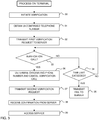
- FIG. 2 shows an embodiment of a verification process executed in the network environment of FIG. 1 to verify that an unconfirmed telephone number, which is entered through the terminal 10, corresponds to an actual subscription telephone number and that this subscription telephone number is associated with the terminal 10.
- the verification process is performed by a verification application executed on the terminal 10 and a verification service executed on the verification server 14.
- the verification process involves setting up a unique call from a PSTN server 18 to the unconfirmed telephone number, and checking if the call is received by the terminal 10. If the call is received, the verification server 14 concludes that the unconfirmed telephone number is a subscription telephone number associated with the terminal 10.
- the verification process is particularly, but not exclusively, useful for verifying mobile telephone numbers.
- the terminal 10 sends a first or initial verification request VR1 to the verification server 14 (step 20).
- the request VR1 includes an unconfirmed telephone number, designated by MY#.
- the verification server 14 sends a call request CR to the PSTN server 18 (step 21).
- the call request CR includes MY# and a selected calling telephone number, designated by CALLER#.
- CALLER# is selected by the server 14.
- the call request CR causes the PSTN server 18 to place a verification call to MY# from CALLER# (step 22).
- the terminal 10 cancels the verification call after having determined the originating telephone number of the incoming call, designated by ORIGIN# (step 23).
- the terminal 10 then sends a second verification request VR2 to the server 14.
- the request VR2 includes MY# and ORIGIN# (step 24).
- the server 14 compares ORIGIN# to CALLER#. If they match, the verification is deemed successful, otherwise the verification is deemed to fail.
- the server 14 may also send a confirmation message CONF to the terminal 10 indicating if the verification was successful or not (step 25).
- the verification process may provide access to a service in different ways.
- the server 14 gives the verification application on the terminal 10 access to another service on the server 14 or on another server connected to the network 12B, when the server finds that ORIGIN# matches CALLER#.
- the verification application on the terminal 10 gives another application program on the terminal 10 access to a service on the server 14 or on another server connected to the network 12B, when the verification application receives the confirmation message CONF.
- the verification process in FIG. 2 may be performed automatically, without requiring any user intervention via the terminal 10. It may also be hidden to the user, i.e. the steps 20-25 may be executed without the user being informed about the respective steps or the verification call. Furthermore, the verification process may be performed without incurring any cost for the user or the provider of the verification service, e.g. by terminating the verification call without answering. Still further, it is difficult for the user to deceive the verification process, since the actual verification is made remote from the terminal 10, on the server-side. The user cannot manipulate the verification call, which is generated under control of the server 14 and is placed from the PSTN server 18. Conventional measures may be taken to prevent user access to the verification application on the terminal 10, which executes the verification process on the terminal-side.
- the verification process may be used whenever there is a need to verify a telephone number, and to thereby indirectly verify a user to a service. A few examples are given below.
- a provider of a VoIP service may give the user free calls, free call time credits, free text messages, a free month of usage, etc. This may provide an incentive for a user to register multiple times with the same service, to gain access to more free items.
- the provider may implement the inventive verification process as part of the registration procedure and require the user to enter a subscription telephone number. The user is only granted access to the service, and to the free items, if the entered subscription telephone number is verified by the verification process.
- a service that allows a user to make an outgoing telephone call or send a text message through an application program or a web page on the terminal 10 may need to present the caller/sender to the recipient of the call/text message.
- a user may enter an incorrect phone number as caller/sender.
- the service provider may implement the inventive verification process as part of a registration procedure, a log-in procedure, or whenever a user wants to make an outgoing call or send a text message through the service, to ensure that the telephone number entered by the user is validly associated with the user.
- Viber is an instant messaging and VoIP application program.
- the VoIP application program Upon installation on the terminal, the VoIP application program creates a user account with a phone number as username.
- the service synchronizes with the address book in the terminal. Since all users are registered by their phone number, the service returns to the terminal information about all Viber users among the contacts in the address book. In such a service, it may be vital that the phone numbers provided to the service are verified.
- the inventive verification process may be implemented as part of the installation process to ensure that the entered phone number is validly associated with the user.
- a dating service may require its users to enter a telephone number when registering for the service.
- the dating service may implement the inventive verification process as part of the registration procedure, or at a later stage, to verify that the telephone number entered by the user is a subscription telephone number validly associated with the user.
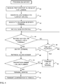
- FIG. 3 is a flow chart illustrating an embodiment of the terminal-side of the verification process in FIG. 2 .
- the verification process is initiated, e.g. by a user of the terminal 10, by another application program on the terminal, or by a service on a server to which the terminal 10 has connected. Thus, the verification process may be initiated on request by the user or automatically.
- an unconfirmed telephone number (MY#) is obtained. The unconfirmed telephone number may be entered manually by the user, retrieved from a phone book on the terminal 10, provided for verification by another application program on the terminal 10 or by a service via a web page on the terminal 10.
- step 32 (corresponding to step 20 in FIG.
- Step 33 may start a monitoring process on the terminal, if not already started, to monitor or intercept all incoming calls. This monitoring process may be implemented by dedicated intercept software included in or used by the verification application on the terminal 10. The verification call may be identified by the monitoring process in different ways. In one alternative, the first incoming call after step 32 is identified as the verification call.
- step 33 will identify the verification call as the first incoming call that originates from a telephone number that matches this group of telephone numbers.
- the group of telephone numbers may e.g. be stored in any format in the memory of the terminal 10. If no verification call is received within a given time limit (step 34), a fail message is transmitted to the server 14 to indicate that the verification failed (step 35). If the verification call is received (corresponding to step 22 in FIG. 2 ), the originating phone number (ORIGIN#) of the verification call is determined (step 36), if not already determined during steps 33-34. The originating phone number may be obtained as the CID for the incoming call.
- the CID represents the caller's number and is transmitted during the ringing signal, or when the call is being set up but before the call is answered.
- the originating phone number for a call can be retrieved without answering the call.
- the verification call is canceled, e.g. by terminating the call or by presenting a busy signal to the caller.
- the second verification request (VR2) is transmitted to the server 14 with the unconfirmed telephone number and the originating phone number. If the terminal 10 receives a confirmation from the server 14 indicating that the verification has succeeded (step 38), the terminal 10 may e.g. proceed to access a particular service (step 39).
- FIG. 4 is a flow chart illustrating an embodiment of the server-side of the verification process in FIG. 2 .
- step 40 the first verification request (VR1) is received, causing the server 14 to assign a calling number (CALLER#) for the verification call (step 41).
- the calling number is typically selected from a pool of telephone numbers that have been acquired for use by the verification service. Information about available calling numbers may be stored in a memory of the server 14.
- step 42 an association between the calling number and the terminal (e.g., the unconfirmed telephone number) is stored in the memory.
- step 43 the verification call is initiated by transmitting the call request (CR) to the PSTN server 18.
- CR call request
- step 44 the process waits for the second verification request (VR2). If the second verification request is not received within a given time limit (step 45), the verification is deemed to fail and a corresponding confirmation (CONF) is transmitted to the terminal (step 46). If the second verification request is received, the terminal is identified (step 47), e.g. by the unconfirmed telephone number (MY#) included in the second verification request, and the calling number corresponding to the terminal is retrieved from the memory of the server (step 48). In step 49, the originating phone number (ORIGIN#) included in the second verification request is compared to the calling number retrieved in step 48. If they match, the verification is deemed to succeed, otherwise the verification is deemed to fail (step 50). A corresponding confirmation (CONF) is transmitted to the terminal (step 46).
- MY# unconfirmed telephone number
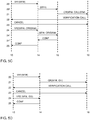
- FIG. 2 may be modified in many different ways without departing from the underlying concept of the present invention. A few alternative embodiments will be briefly discussed with reference to FIGS 5A-5D , with focus on differences compared to FIG. 2 .
- step 20 is modified to include a unique terminal identifier ID in the first verification request VR1.
- the terminal identifier may be predefined and stored in a memory of the terminal 10, or it may be dynamically assigned by or for the terminal 10 prior to generating the first verification request VR1.
- the terminal identifier is used by the verification server 14 in step 21 to associate the calling number CALLER# with the terminal 10. Consequently, step 24 is also modified by including the terminal identifier ID in the second verification request VR2 instead of the unconfirmed telephone number MY#.
- the terminal-side is identical to FIG. 2 whereas the server-side differs in that the verification server 14 has delegated the generation of the call request CR to another server 16. Nevertheless, the verification call is initiated by the verification server 14 in step 20'.
- the verification server 14 transmits a specific request (including the unconfirmed telephone number MY#) to the server 16 that causes the server 16 to independently assign a calling number CALLER# and generate and transmit the call request CR.
- the server 16 informs the verification server 14 about the calling number CALLER# assigned to the unconfirmed telephone number MY#.
- the terminal-side is also identical to FIG. 2 whereas the server-side differs in that the verification server 14 has delegated both the generation of the call request CR and the comparing of CALLER# to ORIGIN# to another server 16.
- the verification server 14 transmits a specific request (including the unconfirmed telephone number MY#) to the server 16 that causes the server 16 to independently assign a calling number CALLER# and generate and transmit the call request CR.
- the server 16 does not return CALLER# to the verification server 14, but stores an association MY# : CALLER#.
- step 24' when the verification server 14 has received the second verification request VR2 from the terminal 10, the verification server 14 sends a specific request (including MY# and ORIGIN#) to the server 16 that causes the server 16 to retrieve CALLER# associated with MY# and compare ORIGIN# to the retrieved CALLER#.
- step 24" the server 16 returns a confirmation CONF to the verification server indicating whether there is a match or not. It is understood that the verification server 14, by step 24', controls the process in the server 16 and thus indirectly performs the step of comparing ORIGIN# to CALLER#.
- FIG. 5D illustrates a generalization of the verification process in FIG. 2 , which does not require the verification server 14 to base the verification on a comparison of CALLER# and ORIGIN#. Instead, in step 21, the verification server 14 initiates/generates the call request CR to include the unconfirmed telephone number MY# and an identifier ID1. The identifier is generated by or for the verification server 14 and is associated with the terminal 10 (e.g. by MY#). If required by the PSTN server 18, the call request CR may also include a calling number CALLER#. However, in contrast to the process in FIG. 2 , CALLER# need not be unique. The call request CR causes the PSTN server 18 to include ID1 in the verification call to MY#.
- the call request CR is therefore configured to cause the PSTN server 18 to encode the first identifier ID1 as signals (sounds) transmitted by the voice call, e.g. using DTMF (Dual-tone multi-frequency signaling).
- the verification call is intercepted by the terminal-side process, in step 22, the verification call is answered and the encoded signals are decoded into a received identifier value, designated by ID2 in FIG. 5D .
- the verification call is then cancelled in step 23, whereupon the identifier value ID2 is sent to the verification server 14 together with MY# in the second verification request VR2 (step 24).
- the verification server 14 then verifies the user by validating the received identifier value ID2, e.g. by retrieving the first identifier ID1 (based on MY#) and comparing ID2 to ID1.
- the terminal-side process in FIG. 5D may performed automatically and hidden to the user of the terminal 10.
- FIGS 3-4 are also relevant for the embodiments in FIGS 5A-5D and FIGS 8A-8B (see below) with modifications that should be evident to the skilled person based on the teachings presented herein and will not be discussed in further detail.
- FIG. 6 is a block diagram of the terminal 10 illustrating functional blocks that are used or instantiated during execution of the verification process as presented in FIGS 2-4 . It is to be understood that the respective block may be implemented by hardware and/or software.
- blocks 60A, 60B and 64 may be implemented by software, e.g. an application program, and blocks 62 and 66 may exist on the terminal 10 independent of the application program and may be implemented by hardware and/or software.
- the terminal 10 includes a first request handler 60A which implements steps 30-32 in FIG. 3 .
- the handler 60A is operable to connect to a data communication interface 62 for transmission of the first verification request VR1 to the server (not shown).
- a verification call detector or intercept module 64 implements steps 33-36 in FIG. 3 .
- the detector 64 is operable to connect to a voice call interface 66 for interception and detection of the verification call.
- the handler 60A is operable to directly or indirectly initiate the detector 64 to start monitoring incoming calls on the interface 66.
- the terminal 10 further includes a second request handler 60B which implements steps 37-38 in FIG. 3 .
- the handler 60B is thus operable to obtain the originating telephone number ORIGIN# determined by the detector 64.
- the handler 60B is further operable to connect to the interface 62 for transmission of the second verification request VR2 to the server (not shown).
- FIG. 7 is a block diagram of the verification server 14 illustrating functional blocks that are used or instantiated during execution of the verification process as presented in FIGS 2-4 .
- the respective block may be implemented by hardware and/or software.
- blocks 70A, 70B and 74 may be implemented by software, e.g. a server program, and blocks 72 and 76 may exist on the server 14 independent of the server program and may be implemented by hardware and/or software.
- the server 14 includes a first request handler 70A which implements step 40 in FIG. 4 .
- the handler 70A is operable to connect to a data communication interface 72 for receiving the first verification request VR1 from the terminal (not shown).
- a call initiation module 74 implements steps 41-43 in FIG. 4 .
- the module 74 is operable to receive the unconfirmed telephone number MY# determined by the handler 70A.
- the module 74 is further operable to connect to the interface 72 for initiation of the verification call, e.g. by transmitting the call request CR to the PSTN server 18.
- the module 74 is further operable to connect to a memory 76 for storage of the calling number CALLER#, e.g. in association with MY#.
- the server 14 further includes a second request handler 70B which implements steps 44-51 in FIG. 4 .
- the handler 70B is thus operable to connect to the interface 72 for receiving the second verification request VR2 from the terminal (not shown).
- the handler 70B is further operable to connect to the memory 76 for retrieving the originating telephone number ORIGIN#, e.g. based on MY# included in VR2, and to compare CALLER# in VR2 to ORIGIN# for verification.
- FIGS 6-7 are also relevant for the embodiments in FIGS 5A-5D and FIGS 8A-8B (see below) with modifications that should be evident to the skilled person based on the teachings presented herein and will not be discussed in further detail.
- steps 30-32 may be executed by any communication device which is capable of connecting to the telephone or data network 12A, 12B ( Fig. 1 ), as further exemplified below with reference to FIGS 8A-8B .
- the request VR1 is generated by and transmitted to the server 14 from a communication device 10' other than the terminal 10 (step 20).
- the device 10' may be a computer, a server, a mobile terminal, etc.
- the request VR1 may be generated and transmitted when a user accesses a network service, e.g. via a web browser on a computer/terminal.
- the request VR1 may be generated by and transmitted to the server 14 from the computer/terminal that is operated by the user to access the network service, or from the network service itself.
- the request VR1 may in fact be provided as an internal command on the server 14, e.g. if the network service accessed by the user is the verification service itself.
- the request VR1 in all embodiments and variants disclosed herein, may be either explicit or implicit.
- Such an explicit request VR1 may contain the unconfirmed telephone number MY# to be verified, whereas an implicit request VR1 may neither be formatted as a request or command, nor include MY#.
- the implicit request VR1 may be a simple trigger signal that the server 14 is able to associate with a specific telephone number to be verified.
- the server-side in FIG. 8A is identical to FIG. 2 and will not be further described.
- the server 14 sends the confirmation message CONF to the device 10', although CONF may be sent to the terminal 10 or to any other device, e.g. the network service that is accessed by the user.
- the server 14 may be configured, as part of step 21, to transmit a message to the device 10' or the terminal 10 prompting the user to start the verification process on the terminal 10, e.g. by activating the verification application on the terminal 10.
- the embodiment in FIG. 8B involves yet another communication device 10", which may be a computer, a server, a mobile terminal, etc.
- the device 10" is used in step 20A to provide the unconfirmed telephone number MY# to the server 14, together with user identification data (UID).
- the UID identifies the user and is associated with MY# at the server 14.
- Step 20A may e.g. be performed when the user registers for a service, and the UID may include one or more of a name, a postal address, an email address, a birth date, etc.
- the request VR1 is generated and transmitted from the communication device 10', e.g. as described in relation to FIG. 8A .
- the request VR1 does not include MY# but UID.
- the server 14 identifies MY# based on UID and includes MY# in the call request CR to the PSTN server 18.
- the subsequent steps 22-25 are identical to FIG. 2 and will not be repeated.
- FIG. 9 is a flow chart of steps performed by a verification provider in relation to a user.
- the verification provider supplies a verification application for installation on the terminal 10, the verification application being configured to implement the verification process on the terminal-side.
- the verification application may be supplied as part of the operating system on the terminal 10, or as a software program for selective installation on the terminal 10, e.g. by download.
- the provider allows the user to initiate a request for verification at the verification service. This may e.g. be done via the verification application on the terminal 10 or by providing a web page for access by the user via the terminal 10 or another communication device 10'.
- the user may explicitly command the verification, or the verification may proceed automatically based on some user activity.
- the provider may be seen to enable terminals 10 to perform the verification process, which involves waiting for and detecting the verification call from the verification service (step 92) and sending the second verification request VR2 to the verification service (step 93).
- step 94 the user verification is completed by the verification service on the server 14.
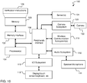
- FIG. 10 is a block diagram of an example architecture 100 of the terminals 10 in FIG. 1 .
- the terminal 10 may include a memory interface 102, one or more processors 104 such as data processors, image processors and/or central processing units, and a peripherals interface 106.
- the memory interface 102, one or more processors 104 and/or peripherals interface 106 may be separate components or integrated in one or more integrated circuits.
- the various components in the terminal 10 may be coupled by one or more communication buses or signal lines. Sensors, devices, and subsystems may be coupled to the peripherals interface 106 to facilitate multiple functionalities.
- Communication functions may be facilitated through one or more wireless communication subsystems 110, which can include radio frequency receivers and transmitters and/or optical (e.g., infrared) receivers and transmitters.
- the specific design and implementation of the communication subsystem 110 may depend on the communication network(s) over which the terminal 10 is intended to operate.
- the terminal 10 may include communication subsystems 110 designed to operate over networks according to any cellular network protocol, such as GMS, GPRS, EDGE, UMTS, CDM and LTE, as well as other networks such as WiFi, WiMax and BluetoothTM.
- An audio subsystem 112 may be coupled to audio hardware component(s) 114, such as a speaker and a microphone, to facilitate voice-enabled functions, such as voice recognition, voice replication, digital recording, and telephony functions, as well as to enable presentation of recorded audio files.
- audio hardware component(s) 114 such as a speaker and a microphone
- An I/O subsystem 116 may include one or more input/output controllers coupled to input/output hardware component(s) 118, including but not limited to one or more of a touch screen, a display, a keyboard, a touch pad, one or more buttons, rocker switches, a thumb-wheel, an infrared port, a USB port, and a pointer device such as a stylus.
- input/output hardware component(s) 118 including but not limited to one or more of a touch screen, a display, a keyboard, a touch pad, one or more buttons, rocker switches, a thumb-wheel, an infrared port, a USB port, and a pointer device such as a stylus.
- a camera subsystem 120 with a camera 122 is connected to the peripherals interface 106 to facilitate camera functions, such as recording photographs and video clips.
- one or more auxiliary sensors 124 such as a motion sensor, orientation sensor, proximity sensor, positioning system (e.g., GPS receiver), temperature sensor, biometric sensor, magnetometer, etc, are coupled to the peripherals interface 106 to facilitate related functionalities.
- the memory interface 102 may be coupled to a memory 108.
- the memory 108 may include high-speed random access memory and/or non-volatile memory, such as one or more magnetic disk storage devices, one or more optical storage devices, and/or flash memory (e.g., NAND, NOR).
- the memory 108 may store an operating system, such as Android, OS X, Windows Mobile, Darwin, RTXC, LINUX, UNIX, or an embedded operating system such as VxWorks.
- the operating system may include instructions for handling basic system services and for performing hardware dependent tasks.
- the operating system may include instructions for performing a verification in relation to a server system providing a service on the data network. For example, the operating system may implement the terminal-side verification process as described with reference to FIGS 1-9 .
- the memory 108 may also store communication instructions to facilitate communicating with one or more additional devices, one or more computers and/or one or more servers.
- the memory 108 may include graphical user interface instructions to facilitate graphic user interface processing; sensor processing instructions to facilitate sensor-related processing and functions; phone instructions to facilitate phone-related processes and functions; electronic messaging instructions to facilitate electronic-messaging related processes and functions; web browsing instructions to facilitate web browsing-related processes and functions; media processing instructions to facilitate media processing-related processes and functions; GPS/Navigation instructions to facilitate GPS and navigation-related processes and instructions; and camera instructions to facilitate camera-related processes and functions.
- the memory 108 may also store information about a user's contacts (names, addresses, phone numbers, etc.), scheduled appointments and events, notes, media assets such as audio, video, still images, or the like, that can be played by the terminal 10, along with metadata describing the media assets (e.g., asset name, artist, title, genre, etc.), playlists (lists of assets that can be played sequentially or in random order), and the like.
- a user's contacts names, addresses, phone numbers, etc.
- scheduled appointments and events such as audio, video, still images, or the like
- media assets such as audio, video, still images, or the like
- metadata describing the media assets e.g., asset name, artist, title, genre, etc.
- playlists lists of assets that can be played sequentially or in random order
- the memory 108 may also store application programs (also referred to herein as "applications” or “apps”) which include any program executable by the processor(s) 104.
- an application may be a program that includes a user interface for enabling interaction with a user.
- an application may be a process that runs in the background, such as a daemon.
- certain applications may be installed on the terminal 10 by its manufacturer, while other applications may be installed by a user.
- Examples of application programs may include video game programs, personal information management programs, programs for playing media assets and/or navigating the media asset database, programs for controlling a telephone interface to place and/or receive calls, and so on.
- one application program 126 may include instructions for performing a verification in relation to a server system providing a verification service.
- the application program 126 may implement the terminal-side verification process as described with reference to FIGS 1-9 .
- the disclosed and other embodiments and the functional operations described in this specification can be implemented in digital electronic circuitry, or in computer software, firmware, or hardware, including the structures disclosed in this specification and their structural equivalents, or in combinations of one or more of them.
- the disclosed and other embodiments can be implemented as one or more computer program products, i.e., one or more modules of computer program instructions encoded on a computer readable medium for execution by, or to control the operation of, a data processing apparatus.
- the computer readable medium can be a machine-readable storage device, a machine-readable storage substrate, a memory device, a composition of matter effecting a machine-readable propagated signal, or any combination thereof.
- data processing apparatus encompasses all apparatus, devices, and machines for processing data, including by way of example a programmable processor, a computer, or multiple processors or computers.
- the apparatus can include, in addition to hardware, code that creates an execution environment for the computer program in question, e.g., code that constitutes processor firmware, a protocol stack, a database management system, an operating system, or a combination of one or more of them.
- a propagated signal is an artificially generated signal, e.g., a machine-generated electrical, optical, or electromagnetic signal, which is generated to encode information for transmission to suitable receiver apparatus.
- a computer program (also known as a program, software, software application, script, or code) can be written in any form of programming language, including compiled or interpreted languages, and it can be deployed in any form, including as a stand-alone program or as a module, component, subroutine, or other unit suitable for use in a computing environment.
- a computer program does not necessarily correspond to a file in a file system.
- a program can be stored in a portion of a file that holds other programs or data (e.g., one or more scripts stored in a markup language document), in a single file dedicated to the program in question, or in multiple coordinated files (e.g., files that store one or more modules, sub programs, or portions of code).
- a computer program can be deployed to be executed on one computer or on multiple computers that are located at one site or distributed across multiple sites and interconnected by a communication network.
- the processes and logic flows described in this specification can be performed by one or more programmable processors executing one or more computer programs to perform functions by operating on input data and generating output.
- the processes and logic flows can also be performed by, and apparatus can also be implemented as, special purpose logic circuitry, e.g., an FPGA (field programmable gate array) or an ASIC (application specific integrated circuit).
- processors suitable for the execution of a computer program include, by way of example, both general and special purpose microprocessors, and any one or more processors of any kind of digital computer.
- a processor will receive instructions and data from a read only memory or a random access memory or both.
Landscapes
- Engineering & Computer Science (AREA)
- Computer Security & Cryptography (AREA)
- Signal Processing (AREA)
- Computer Networks & Wireless Communication (AREA)
- Technology Law (AREA)
- Telephonic Communication Services (AREA)
Claims (15)
- Computerimplementiertes Verfahren, das von einem softwaregesteuerten Kommunikationsgerät (10) durchgeführt wird, das einer Teilnehmertelefonnummer in einem Telefonnetz (12A) zugeordnet ist, wobei das Verfahren umfasst:Betreiben eines Überwachungsprozesses zum Erkennen eines eingehenden Verifizierungsanrufs und Bestimmen einer Ausgangstelefonnummer (ORIGIN#) des eingehenden Verifizierungsanrufs oder einer durch den eingehenden Verifizierungsanruf übertragenen Kennung (ID2), indem der eingehende Verifizierungsanruf als der erste eingehende Anruf identifiziert wird, der von einer Telefonnummer ausgeht, die zu einer Gruppe von Telefonnummern gehört, die dem Kommunikationsgerät bekannt sind, wobei der eingehende Verifizierungsanruf an einem Serversystem (14) eingeleitet wird, um eine unbestätigte Telefonnummer (MY#) zu verifizieren, indem als Reaktion auf eine anfängliche Verifizierungsanforderung (VR1), die die unbestätigte Telefonnummer beinhaltet, der Verifizierungsanruf an die unbestätigte Telefonnummer (MY#) von einer anrufenden Telefonnummer (CALLER#) getätigt wird; undÜbertragen, wenn der Überwachungsprozess den eingehenden Verifizierungsanruf erkennt, einer zweiten Verifizierungsanforderung (VR2) an das Serversystem (14), wobei die zweite Verifizierungsanforderung (VR2) die Ausgangstelefonnummer (ORIGIN#) des eingehenden Verifizierungsanrufs oder die Kennung (ID2) beinhaltet, wodurch dem Serversystem (14) ermöglicht wird, zu verifizieren, dass die unbestätigte Telefonnummer (MY#) eine Teilnehmertelefonnummer ist, die dem Kommunikationsgerät (10) zugewiesen ist, indem die Ausgangstelefonnummer (ORIGIN#) mit der anrufenden Telefonnummer (CALLER#) verglichen wird oder die Kennung (ID2) validiert wird.
- Verfahren nach Anspruch 1, wobei der eingehende Verifizierungsanruf am Kommunikationsgerät (10) beendet wird, ohne beantwortet zu werden.
- Verfahren nach Anspruch 1 oder 2, wobei der Überwachungsprozess zum Erkennen des eingehenden Verifizierungsanrufs als den ersten eingehenden Anruf, der vom Kommunikationsgerät (10) innerhalb eines vordefinierten Zeitraums empfangen wird, betrieben wird.
- Verfahren nach einem der Ansprüche 1-3, wobei der Überwachungsprozess den eingehenden Verifizierungsanruf abfängt, ohne den Benutzer des Kommunikationsgeräts zu benachrichtigen (10).
- Verfahren nach einem der Ansprüche 1-4, wobei der eingehende Verifizierungsanruf vor dem Benutzer verborgen wird.
- Verfahren nach einem der Ansprüche 1-5, wobei die Verifizierungsanforderung (VR2) ferner die unbestätigte Telefonnummer (MY#) beinhaltet.
- Verfahren nach einem der Ansprüche 1-6, ferner umfassend, wenn der Überwachungsprozess den eingehenden Verifizierungsanruf nicht innerhalb eines maximalen Zeitraums erkennt, Senden einer Fehlernachricht an das Serversystem (14).
- Verfahren nach einem der Ansprüche 1-7, ferner umfassend: Empfangen einer Statusmeldung (CONF) vom Serversystem (14), die angibt, dass die Verifizierung durch das Serversystem (14) erfolgreich war oder fehlgeschlagen ist.
- Verfahren nach einem der Ansprüche 1 bis 8, ferner umfassend: Empfangen einer Anforderung zur Verifizierung in Bezug auf das Serversystem (14); Erhalten der unbestätigten Telefonnummer (MY#); und Übertragen der anfänglichen Anforderung (VR1) zur Verifizierung vom Kommunikationsgerät (10) an das Serversystem (14), wobei die anfängliche Anforderung (VR1) die unbestätigte Telefonnummer (MY#) beinhaltet und dafür ausgelegt ist, das Serversystem (14) zu veranlassen, den Verifizierungsanruf vom Telefonnetz (12A) an die unbestätigte Telefonnummer (MY#) von der anrufenden Telefonnummer (CALLER#) aus einzuleiten.
- Verfahren nach Anspruch 9, wobei der Überwachungsprozess zum Erkennen des eingehenden Verifizierungsanrufs als den ersten eingehenden Anruf, der vom Kommunikationsgerät (10) innerhalb eines vordefinierten Zeitraums ab der Übertragung der anfänglichen Anforderung (VR1) empfangen wird, betrieben wird.
- Verfahren nach einem der vorhergehenden Ansprüche, wobei die Gruppe von Telefonnummern in einem beliebigen Format in einem Speicher des Kommunikationsgeräts gespeichert ist.
- Computerlesbares Medium, umfassend Programmanweisungen, die bei ihrer Ausführung durch einen Prozessor (104) in einem Kommunikationsgerät (10), das einer Teilnehmertelefonnummer in einem Telefonnetz (12A) zugeordnet ist, das Verfahren nach einem der Ansprüche 1-11 durchführen.
- Computerimplementiertes Verifizierungssystem auf einem Kommunikationsgerät (10), das einer Teilnehmertelefonnummer in einem Telefonnetz (12A) zugeordnet ist, wobei das Verifizierungssystem umfasst:einen Verifizierungsanrufdetektor (64), der zum Überwachen einer Sprachanrufschnittstelle (66; 110) im Kommunikationsgerät (10) ausgelegt ist, zum Erkennen eines eingehenden Verifizierungsanrufs und Bestimmen einer Ausgangstelefonnummer (ORIGIN#) des eingehenden Verifizierungsanrufs oder einer durch den eingehenden Verifizierungsanruf übertragenen Kennung (ID2), indem der eingehende Verifizierungsanruf als der erste eingehende Anruf identifiziert wird, der von einer Telefonnummer ausgeht, die zu einer Gruppe von Telefonnummern gehört, die dem Kommunikationsgerät (10) bekannt sind, wobei der eingehende Verifizierungsanruf an einem Serversystem (14) eingeleitet wird, um eine unbestätigte Telefonnummer (MY#) zu verifizieren, indem als Antwort auf eine anfängliche Verifizierungsanforderung (VR1), die die unbestätigte Telefonnummer beinhaltet, der Verifizierungsanruf an die unbestätigte Telefonnummer (MY#) von einer anrufenden Telefonnummer (CALLER#) aus getätigt wird; undeinen Anforderungsbearbeiter (60B), der dafür ausgelegt ist, wenn der eingehende Verifizierungsanruf erkannt wird, eine zweite Verifizierungsanforderung (VR2) zu erzeugen, die die Ausgangstelefonnummer (ORIGIN#) des eingehenden Verifizierungsanrufs oder die Kennung (ID2) beinhaltet, und die zweite Verifizierungsanforderung (VR2) an das Serversystem (14) zu übertragen, wodurch dem Serversystem (14) ermöglicht wird, zu verifizieren, dass die unbestätigte Telefonnummer (MY#) eine dem Kommunikationsgerät (10) zugewiesene Teilnehmertelefonnummer ist, indem die Ausgangstelefonnummer (ORIGIN#) mit der anrufenden Telefonnummer (CALLER#) verglichen wird oder die Kennung (ID2) validiert wird.
- Computerimplementiertes Verifizierungssystem von Anspruch 13, ferner umfassend einen Bearbeiter für anfängliche Anforderungen (60A), der dafür ausgelegt ist, eine anfängliche Anforderung (VR1) zur Verifizierung zu erzeugen, die die unbestätigte Telefonnummer (MY#) beinhaltet und dafür ausgelegt ist, das Serversystem (14) zu veranlassen, den Verifizierungsanruf an die unbestätigte Telefonnummer (MY#) von der anrufenden Telefonnummer (CALLER#) aus einzuleiten und die anfängliche Anforderung (VR1) über eine Datenkommunikationsschnittstelle (62; 110) im Kommunikationsgerät (10) an das Serversystem (14) zu übertragen.
- Verfahren zum Ermöglichen der Verifizierung eines Benutzers, umfassend:Ermöglichen für den Benutzer, eine Anforderung (VR1) zur Verifizierung einer unbestätigten Telefonnummer (MY#) bei einem Serversystem (14) einzuleiten, um das Serversystem (14) zu veranlassen, einen Verifizierungsanruf von einem Telefonnetz (12A) an die unbestätigte Telefonnummer (MY#) von einer anrufenden Telefonnummer (CALLER#) aus einzuleiten; undBereitstellen, für den Benutzer, eines Computerprogramms (126) zur Installation in einem Kommunikationsgerät (10), wobei das Computerprogramm (126) zum Durchführen des Verfahrens nach einem der Ansprüche 1-11 betreibbar ist.
Applications Claiming Priority (2)
| Application Number | Priority Date | Filing Date | Title |
|---|---|---|---|
| US201562138145P | 2015-03-25 | 2015-03-25 | |
| PCT/SE2015/051330 WO2016153407A1 (en) | 2015-03-25 | 2015-12-12 | Methods and systems for verifying users by telephone numbers |
Publications (3)
| Publication Number | Publication Date |
|---|---|
| EP3275165A1 EP3275165A1 (de) | 2018-01-31 |
| EP3275165A4 EP3275165A4 (de) | 2018-08-08 |
| EP3275165B1 true EP3275165B1 (de) | 2020-06-24 |
Family
ID=56976605
Family Applications (1)
| Application Number | Title | Priority Date | Filing Date |
|---|---|---|---|
| EP15886620.2A Active EP3275165B1 (de) | 2015-03-25 | 2015-12-12 | Verfahren und systeme zur verifizierung von benutzern durch telefonnummern |
Country Status (5)
| Country | Link |
|---|---|
| US (1) | US10244106B2 (de) |
| EP (1) | EP3275165B1 (de) |
| CN (1) | CN107710725B (de) |
| ES (1) | ES2817936T3 (de) |
| WO (1) | WO2016153407A1 (de) |
Families Citing this family (6)
| Publication number | Priority date | Publication date | Assignee | Title |
|---|---|---|---|---|
| CN108111462A (zh) * | 2016-11-24 | 2018-06-01 | 上海掌门科技有限公司 | 用于用户设备通信号码验证的方法与设备 |
| CN107483398B (zh) * | 2017-06-28 | 2019-04-19 | 北京三快在线科技有限公司 | 一种静默验证方法及装置,电子设备 |
| EP3503517B1 (de) * | 2017-12-22 | 2019-11-06 | Mitel Cloud Services, Inc. | Freigabe eines benutzerzugriffs auf eine cloud-basierte anwendung |
| US10341485B1 (en) * | 2018-05-16 | 2019-07-02 | Fmr Llc | Caller identity and authentication service |
| CN112422750A (zh) * | 2019-08-22 | 2021-02-26 | 中兴通讯股份有限公司 | 获取终端状态的方法、终端、系统及计算机可读存储介质 |
| US11716426B2 (en) * | 2020-06-21 | 2023-08-01 | Apple Inc. | Techniques for implementing phone number-based user accounts with permissions to access varying levels of services utilizing visible and hidden contact addresses |
Family Cites Families (16)
| Publication number | Priority date | Publication date | Assignee | Title |
|---|---|---|---|---|
| DE19622068C2 (de) * | 1996-05-31 | 1999-11-11 | Siemens Ag | Verfahren zur Zulässigkeitsprüfung von Rufnummern von an einem Kommunikationssystem ankommenden Anrufen |
| US5995603A (en) * | 1997-05-23 | 1999-11-30 | At&T Corp | Telephone call screening device |
| SE510954C2 (sv) * | 1997-11-11 | 1999-07-12 | Ericsson Telefon Ab L M | Metod och anordning för verifiering av talportstjänster |
| US6285750B1 (en) * | 1998-12-03 | 2001-09-04 | At&T Corp. | Method and apparatus for remotely controlling telephone call-forwarding |
| US7460653B2 (en) | 2003-03-07 | 2008-12-02 | Callwave, Inc. | Apparatus and methods for telecommunication authentication |
| US20060153346A1 (en) * | 2005-01-11 | 2006-07-13 | Metro Enterprises, Inc. | On-line authentication registration system |
| JP4813272B2 (ja) * | 2006-07-07 | 2011-11-09 | 日本電信電話株式会社 | ユーザ認証方法、ユーザ認証システム、ユーザ認証装置及びユーザ認証プログラム |
| CN101447872B (zh) * | 2007-11-27 | 2011-09-28 | 阿里巴巴集团控股有限公司 | 一种用户身份验证方法、系统及验证码生成维护子系统 |
| MY165460A (en) * | 2008-12-18 | 2018-03-22 | Pin Yong Lai | Authentication using telecommunications device |
| US8995965B1 (en) * | 2010-03-25 | 2015-03-31 | Whatsapp Inc. | Synthetic communication network method and system |
| EP2888893B1 (de) | 2012-08-26 | 2018-04-18 | Barkan, Elad, Pinhas | Umleitung von mobiltelefonkommunikation durch ein datennetzwerk |
| US9338287B1 (en) * | 2012-10-09 | 2016-05-10 | Whatsapp Inc. | Automated verification of a telephone number |
| MY172205A (en) * | 2013-05-20 | 2019-11-15 | Celltrust Corp | System and method for tracking sms messages |
| US9615222B2 (en) | 2013-08-05 | 2017-04-04 | GTA Wireless Direct Ltd. | System and method for simplifying mobile device account creation and verification |
| US9338297B2 (en) * | 2014-01-20 | 2016-05-10 | Avaya Inc. | Setup application for generating custom code |
| US9516480B2 (en) * | 2014-11-24 | 2016-12-06 | Nexmo Inc. | Identity and phone number verification |
-
2015
- 2015-12-12 EP EP15886620.2A patent/EP3275165B1/de active Active
- 2015-12-12 CN CN201580080308.4A patent/CN107710725B/zh active Active
- 2015-12-12 ES ES15886620T patent/ES2817936T3/es active Active
- 2015-12-12 WO PCT/SE2015/051330 patent/WO2016153407A1/en active Application Filing
- 2015-12-15 US US14/969,233 patent/US10244106B2/en active Active
Non-Patent Citations (1)
| Title |
|---|
| None * |
Also Published As
| Publication number | Publication date |
|---|---|
| EP3275165A4 (de) | 2018-08-08 |
| WO2016153407A1 (en) | 2016-09-29 |
| CN107710725B (zh) | 2020-10-13 |
| US10244106B2 (en) | 2019-03-26 |
| CN107710725A (zh) | 2018-02-16 |
| EP3275165A1 (de) | 2018-01-31 |
| US20160286041A1 (en) | 2016-09-29 |
| ES2817936T3 (es) | 2021-04-08 |
Similar Documents
| Publication | Publication Date | Title |
|---|---|---|
| EP3275165B1 (de) | Verfahren und systeme zur verifizierung von benutzern durch telefonnummern | |
| US8831581B2 (en) | System and methods of initiating a call | |
| US8861692B1 (en) | Web call access and egress to private network | |
| US10423958B2 (en) | Method, apparatus and system for voice verification | |
| US8204484B2 (en) | System and method for managing missed calls and unread messages | |
| EP3162104B1 (de) | Verfahren zur authentifizierung von anrufen in einem telekommunikationssystem | |
| US20100190474A1 (en) | Systems and methods for managing mobile communications | |
| US9060275B2 (en) | Interface for synchronizing automated replies between different messaging systems | |
| US20180103144A1 (en) | Methods, apparatus and devices for authenticating a call session | |
| US9730053B2 (en) | Concepts for enhanced call control | |
| US20110319061A1 (en) | Automated Mobile Intelligent Communication Processing System | |
| US20140134988A1 (en) | Enhancing information delivery to a called party | |
| US10805462B1 (en) | Techniques for providing SOS call routing for emergency calls | |
| US10142494B2 (en) | Enforcement of compliance rules | |
| WO2014110991A1 (zh) | 一种信息实时展示的方法和移动通讯终端 | |
| US20140177579A1 (en) | Systems and Methods for Establishing a Telecommunications Bridge Between a User Device and a Node | |
| US10616418B2 (en) | Dynamically generated call triggers | |
| US9002350B1 (en) | Unified caller identification across multiple communication modes | |
| US20200304627A1 (en) | Incoming Voice Calling Method and Terminal | |
| CN114915923A (zh) | 5g消息即服务触发方法、装置、电子设备及存储介质 | |
| CN111988473B (zh) | 基于智能合约的语音通信呼叫控制方法及装置 | |
| US9544426B2 (en) | Method for transmitting data related to a call | |
| WO2014074936A2 (en) | Enhancing information delivery to a called party | |
| KR20150031503A (ko) | 그룹정보를 이용한 발신번호 유효성 확인 방법 | |
| KR101931650B1 (ko) | 발신정보 인증 시스템 및 방법 |
Legal Events
| Date | Code | Title | Description |
|---|---|---|---|
| STAA | Information on the status of an ep patent application or granted ep patent |
Free format text: STATUS: THE INTERNATIONAL PUBLICATION HAS BEEN MADE |
|
| PUAI | Public reference made under article 153(3) epc to a published international application that has entered the european phase |
Free format text: ORIGINAL CODE: 0009012 |
|
| STAA | Information on the status of an ep patent application or granted ep patent |
Free format text: STATUS: REQUEST FOR EXAMINATION WAS MADE |
|
| 17P | Request for examination filed |
Effective date: 20171013 |
|
| AK | Designated contracting states |
Kind code of ref document: A1 Designated state(s): AL AT BE BG CH CY CZ DE DK EE ES FI FR GB GR HR HU IE IS IT LI LT LU LV MC MK MT NL NO PL PT RO RS SE SI SK SM TR |
|
| AX | Request for extension of the european patent |
Extension state: BA ME |
|
| RAP1 | Party data changed (applicant data changed or rights of an application transferred) |
Owner name: SINCH AB |
|
| RIN1 | Information on inventor provided before grant (corrected) |
Inventor name: FORSMAN, DANIEL Inventor name: FRANSSON, BJOERN Inventor name: RIKAKIS, MICHAIL |
|
| DAV | Request for validation of the european patent (deleted) | ||
| DAX | Request for extension of the european patent (deleted) | ||
| A4 | Supplementary search report drawn up and despatched |
Effective date: 20180711 |
|
| RIC1 | Information provided on ipc code assigned before grant |
Ipc: H04W 8/26 20090101ALI20180705BHEP Ipc: H04W 4/16 20090101ALI20180705BHEP Ipc: H04M 3/42 20060101AFI20180705BHEP Ipc: H04M 3/22 20060101ALI20180705BHEP |
|
| RIC1 | Information provided on ipc code assigned before grant |
Ipc: H04M 3/42 20060101AFI20191126BHEP Ipc: H04W 12/12 20090101ALI20191126BHEP Ipc: H04W 8/26 20090101ALI20191126BHEP Ipc: H04W 12/08 20090101ALI20191126BHEP Ipc: H04W 4/16 20090101ALI20191126BHEP Ipc: H04M 3/22 20060101ALI20191126BHEP |
|
| GRAP | Despatch of communication of intention to grant a patent |
Free format text: ORIGINAL CODE: EPIDOSNIGR1 |
|
| STAA | Information on the status of an ep patent application or granted ep patent |
Free format text: STATUS: GRANT OF PATENT IS INTENDED |
|
| INTG | Intention to grant announced |
Effective date: 20200107 |
|
| GRAS | Grant fee paid |
Free format text: ORIGINAL CODE: EPIDOSNIGR3 |
|
| GRAA | (expected) grant |
Free format text: ORIGINAL CODE: 0009210 |
|
| STAA | Information on the status of an ep patent application or granted ep patent |
Free format text: STATUS: THE PATENT HAS BEEN GRANTED |
|
| AK | Designated contracting states |
Kind code of ref document: B1 Designated state(s): AL AT BE BG CH CY CZ DE DK EE ES FI FR GB GR HR HU IE IS IT LI LT LU LV MC MK MT NL NO PL PT RO RS SE SI SK SM TR |
|
| REG | Reference to a national code |
Ref country code: GB Ref legal event code: FG4D |
|
| REG | Reference to a national code |
Ref country code: CH Ref legal event code: EP |
|
| REG | Reference to a national code |
Ref country code: AT Ref legal event code: REF Ref document number: 1285063 Country of ref document: AT Kind code of ref document: T Effective date: 20200715 |
|
| REG | Reference to a national code |
Ref country code: DE Ref legal event code: R096 Ref document number: 602015054915 Country of ref document: DE |
|
| REG | Reference to a national code |
Ref country code: IE Ref legal event code: FG4D |
|
| REG | Reference to a national code |
Ref country code: SE Ref legal event code: TRGR |
|
| RAP2 | Party data changed (patent owner data changed or rights of a patent transferred) |
Owner name: SINCH MOBILE AB |
|
| PG25 | Lapsed in a contracting state [announced via postgrant information from national office to epo] |
Ref country code: NO Free format text: LAPSE BECAUSE OF FAILURE TO SUBMIT A TRANSLATION OF THE DESCRIPTION OR TO PAY THE FEE WITHIN THE PRESCRIBED TIME-LIMIT Effective date: 20200924 Ref country code: GR Free format text: LAPSE BECAUSE OF FAILURE TO SUBMIT A TRANSLATION OF THE DESCRIPTION OR TO PAY THE FEE WITHIN THE PRESCRIBED TIME-LIMIT Effective date: 20200925 Ref country code: FI Free format text: LAPSE BECAUSE OF FAILURE TO SUBMIT A TRANSLATION OF THE DESCRIPTION OR TO PAY THE FEE WITHIN THE PRESCRIBED TIME-LIMIT Effective date: 20200624 Ref country code: LT Free format text: LAPSE BECAUSE OF FAILURE TO SUBMIT A TRANSLATION OF THE DESCRIPTION OR TO PAY THE FEE WITHIN THE PRESCRIBED TIME-LIMIT Effective date: 20200624 |
|
| REG | Reference to a national code |
Ref country code: LT Ref legal event code: MG4D |
|
| PG25 | Lapsed in a contracting state [announced via postgrant information from national office to epo] |
Ref country code: LV Free format text: LAPSE BECAUSE OF FAILURE TO SUBMIT A TRANSLATION OF THE DESCRIPTION OR TO PAY THE FEE WITHIN THE PRESCRIBED TIME-LIMIT Effective date: 20200624 Ref country code: RS Free format text: LAPSE BECAUSE OF FAILURE TO SUBMIT A TRANSLATION OF THE DESCRIPTION OR TO PAY THE FEE WITHIN THE PRESCRIBED TIME-LIMIT Effective date: 20200624 Ref country code: HR Free format text: LAPSE BECAUSE OF FAILURE TO SUBMIT A TRANSLATION OF THE DESCRIPTION OR TO PAY THE FEE WITHIN THE PRESCRIBED TIME-LIMIT Effective date: 20200624 Ref country code: BG Free format text: LAPSE BECAUSE OF FAILURE TO SUBMIT A TRANSLATION OF THE DESCRIPTION OR TO PAY THE FEE WITHIN THE PRESCRIBED TIME-LIMIT Effective date: 20200924 |
|
| REG | Reference to a national code |
Ref country code: NL Ref legal event code: MP Effective date: 20200624 |
|
| REG | Reference to a national code |
Ref country code: AT Ref legal event code: MK05 Ref document number: 1285063 Country of ref document: AT Kind code of ref document: T Effective date: 20200624 |
|
| PG25 | Lapsed in a contracting state [announced via postgrant information from national office to epo] |
Ref country code: AL Free format text: LAPSE BECAUSE OF FAILURE TO SUBMIT A TRANSLATION OF THE DESCRIPTION OR TO PAY THE FEE WITHIN THE PRESCRIBED TIME-LIMIT Effective date: 20200624 Ref country code: NL Free format text: LAPSE BECAUSE OF FAILURE TO SUBMIT A TRANSLATION OF THE DESCRIPTION OR TO PAY THE FEE WITHIN THE PRESCRIBED TIME-LIMIT Effective date: 20200624 |
|
| PG25 | Lapsed in a contracting state [announced via postgrant information from national office to epo] |
Ref country code: PT Free format text: LAPSE BECAUSE OF FAILURE TO SUBMIT A TRANSLATION OF THE DESCRIPTION OR TO PAY THE FEE WITHIN THE PRESCRIBED TIME-LIMIT Effective date: 20201026 Ref country code: AT Free format text: LAPSE BECAUSE OF FAILURE TO SUBMIT A TRANSLATION OF THE DESCRIPTION OR TO PAY THE FEE WITHIN THE PRESCRIBED TIME-LIMIT Effective date: 20200624 Ref country code: RO Free format text: LAPSE BECAUSE OF FAILURE TO SUBMIT A TRANSLATION OF THE DESCRIPTION OR TO PAY THE FEE WITHIN THE PRESCRIBED TIME-LIMIT Effective date: 20200624 Ref country code: CZ Free format text: LAPSE BECAUSE OF FAILURE TO SUBMIT A TRANSLATION OF THE DESCRIPTION OR TO PAY THE FEE WITHIN THE PRESCRIBED TIME-LIMIT Effective date: 20200624 Ref country code: EE Free format text: LAPSE BECAUSE OF FAILURE TO SUBMIT A TRANSLATION OF THE DESCRIPTION OR TO PAY THE FEE WITHIN THE PRESCRIBED TIME-LIMIT Effective date: 20200624 Ref country code: SM Free format text: LAPSE BECAUSE OF FAILURE TO SUBMIT A TRANSLATION OF THE DESCRIPTION OR TO PAY THE FEE WITHIN THE PRESCRIBED TIME-LIMIT Effective date: 20200624 |
|
| PG25 | Lapsed in a contracting state [announced via postgrant information from national office to epo] |
Ref country code: IS Free format text: LAPSE BECAUSE OF FAILURE TO SUBMIT A TRANSLATION OF THE DESCRIPTION OR TO PAY THE FEE WITHIN THE PRESCRIBED TIME-LIMIT Effective date: 20201024 Ref country code: PL Free format text: LAPSE BECAUSE OF FAILURE TO SUBMIT A TRANSLATION OF THE DESCRIPTION OR TO PAY THE FEE WITHIN THE PRESCRIBED TIME-LIMIT Effective date: 20200624 Ref country code: SK Free format text: LAPSE BECAUSE OF FAILURE TO SUBMIT A TRANSLATION OF THE DESCRIPTION OR TO PAY THE FEE WITHIN THE PRESCRIBED TIME-LIMIT Effective date: 20200624 |
|
| REG | Reference to a national code |
Ref country code: DE Ref legal event code: R097 Ref document number: 602015054915 Country of ref document: DE |
|
| REG | Reference to a national code |
Ref country code: ES Ref legal event code: FG2A Ref document number: 2817936 Country of ref document: ES Kind code of ref document: T3 Effective date: 20210408 |
|
| PG25 | Lapsed in a contracting state [announced via postgrant information from national office to epo] |
Ref country code: DK Free format text: LAPSE BECAUSE OF FAILURE TO SUBMIT A TRANSLATION OF THE DESCRIPTION OR TO PAY THE FEE WITHIN THE PRESCRIBED TIME-LIMIT Effective date: 20200624 |
|
| PLBE | No opposition filed within time limit |
Free format text: ORIGINAL CODE: 0009261 |
|
| STAA | Information on the status of an ep patent application or granted ep patent |
Free format text: STATUS: NO OPPOSITION FILED WITHIN TIME LIMIT |
|
| 26N | No opposition filed |
Effective date: 20210325 |
|
| REG | Reference to a national code |
Ref country code: CH Ref legal event code: PL |
|
| PG25 | Lapsed in a contracting state [announced via postgrant information from national office to epo] |
Ref country code: MC Free format text: LAPSE BECAUSE OF FAILURE TO SUBMIT A TRANSLATION OF THE DESCRIPTION OR TO PAY THE FEE WITHIN THE PRESCRIBED TIME-LIMIT Effective date: 20200624 Ref country code: SI Free format text: LAPSE BECAUSE OF FAILURE TO SUBMIT A TRANSLATION OF THE DESCRIPTION OR TO PAY THE FEE WITHIN THE PRESCRIBED TIME-LIMIT Effective date: 20200624 |
|
| PGFP | Annual fee paid to national office [announced via postgrant information from national office to epo] |
Ref country code: IE Payment date: 20210416 Year of fee payment: 6 |
|
| REG | Reference to a national code |
Ref country code: BE Ref legal event code: MM Effective date: 20201231 |
|
| PG25 | Lapsed in a contracting state [announced via postgrant information from national office to epo] |
Ref country code: LU Free format text: LAPSE BECAUSE OF NON-PAYMENT OF DUE FEES Effective date: 20201212 |
|
| PG25 | Lapsed in a contracting state [announced via postgrant information from national office to epo] |
Ref country code: LI Free format text: LAPSE BECAUSE OF NON-PAYMENT OF DUE FEES Effective date: 20201231 Ref country code: CH Free format text: LAPSE BECAUSE OF NON-PAYMENT OF DUE FEES Effective date: 20201231 |
|
| PG25 | Lapsed in a contracting state [announced via postgrant information from national office to epo] |
Ref country code: MT Free format text: LAPSE BECAUSE OF FAILURE TO SUBMIT A TRANSLATION OF THE DESCRIPTION OR TO PAY THE FEE WITHIN THE PRESCRIBED TIME-LIMIT Effective date: 20200624 Ref country code: CY Free format text: LAPSE BECAUSE OF FAILURE TO SUBMIT A TRANSLATION OF THE DESCRIPTION OR TO PAY THE FEE WITHIN THE PRESCRIBED TIME-LIMIT Effective date: 20200624 |
|
| PG25 | Lapsed in a contracting state [announced via postgrant information from national office to epo] |
Ref country code: MK Free format text: LAPSE BECAUSE OF FAILURE TO SUBMIT A TRANSLATION OF THE DESCRIPTION OR TO PAY THE FEE WITHIN THE PRESCRIBED TIME-LIMIT Effective date: 20200624 |
|
| PG25 | Lapsed in a contracting state [announced via postgrant information from national office to epo] |
Ref country code: BE Free format text: LAPSE BECAUSE OF NON-PAYMENT OF DUE FEES Effective date: 20201231 |
|
| PG25 | Lapsed in a contracting state [announced via postgrant information from national office to epo] |
Ref country code: IE Free format text: LAPSE BECAUSE OF NON-PAYMENT OF DUE FEES Effective date: 20211212 |
|
| PGFP | Annual fee paid to national office [announced via postgrant information from national office to epo] |
Ref country code: TR Payment date: 20221121 Year of fee payment: 8 Ref country code: SE Payment date: 20221115 Year of fee payment: 8 Ref country code: IT Payment date: 20221123 Year of fee payment: 8 Ref country code: FR Payment date: 20221116 Year of fee payment: 8 |
|
| P01 | Opt-out of the competence of the unified patent court (upc) registered |
Effective date: 20230821 |
|
| PGFP | Annual fee paid to national office [announced via postgrant information from national office to epo] |
Ref country code: ES Payment date: 20240118 Year of fee payment: 9 |
|
| PGFP | Annual fee paid to national office [announced via postgrant information from national office to epo] |
Ref country code: DE Payment date: 20240117 Year of fee payment: 9 Ref country code: GB Payment date: 20240115 Year of fee payment: 9 |