EP3274988B1 - Controlling electronic device based on direction of speech - Google Patents
Controlling electronic device based on direction of speech Download PDFInfo
- Publication number
- EP3274988B1 EP3274988B1 EP16705671.2A EP16705671A EP3274988B1 EP 3274988 B1 EP3274988 B1 EP 3274988B1 EP 16705671 A EP16705671 A EP 16705671A EP 3274988 B1 EP3274988 B1 EP 3274988B1
- Authority
- EP
- European Patent Office
- Prior art keywords
- speech
- electronic device
- frequency range
- voice command
- user
- Prior art date
- Legal status (The legal status is an assumption and is not a legal conclusion. Google has not performed a legal analysis and makes no representation as to the accuracy of the status listed.)
- Active
Links
- 230000003595 spectral effect Effects 0.000 claims description 62
- 238000000034 method Methods 0.000 claims description 46
- 230000004044 response Effects 0.000 claims description 26
- 230000006870 function Effects 0.000 description 33
- 230000006854 communication Effects 0.000 description 19
- 238000004891 communication Methods 0.000 description 19
- 238000012545 processing Methods 0.000 description 15
- 238000012706 support-vector machine Methods 0.000 description 8
- 238000010586 diagram Methods 0.000 description 6
- 238000013528 artificial neural network Methods 0.000 description 4
- 230000001413 cellular effect Effects 0.000 description 4
- 239000000203 mixture Substances 0.000 description 4
- 101000574648 Homo sapiens Retinoid-inducible serine carboxypeptidase Proteins 0.000 description 3
- 102100025483 Retinoid-inducible serine carboxypeptidase Human genes 0.000 description 3
- 238000001514 detection method Methods 0.000 description 3
- 230000002708 enhancing effect Effects 0.000 description 3
- 230000003287 optical effect Effects 0.000 description 3
- 230000008569 process Effects 0.000 description 3
- 239000007787 solid Substances 0.000 description 3
- 230000001419 dependent effect Effects 0.000 description 2
- 235000019800 disodium phosphate Nutrition 0.000 description 2
- 230000001902 propagating effect Effects 0.000 description 2
- 238000012360 testing method Methods 0.000 description 2
- 238000012546 transfer Methods 0.000 description 2
- 238000003491 array Methods 0.000 description 1
- 230000007175 bidirectional communication Effects 0.000 description 1
- 230000005540 biological transmission Effects 0.000 description 1
- 238000004590 computer program Methods 0.000 description 1
- 230000001143 conditioned effect Effects 0.000 description 1
- 238000012937 correction Methods 0.000 description 1
- 238000013461 design Methods 0.000 description 1
- 238000012986 modification Methods 0.000 description 1
- 230000004048 modification Effects 0.000 description 1
- 239000004984 smart glass Substances 0.000 description 1
- 230000009466 transformation Effects 0.000 description 1
- 230000000007 visual effect Effects 0.000 description 1
Images


Classifications
-
- G—PHYSICS
- G10—MUSICAL INSTRUMENTS; ACOUSTICS
- G10L—SPEECH ANALYSIS OR SYNTHESIS; SPEECH RECOGNITION; SPEECH OR VOICE PROCESSING; SPEECH OR AUDIO CODING OR DECODING
- G10L15/00—Speech recognition
- G10L15/22—Procedures used during a speech recognition process, e.g. man-machine dialogue
-
- G—PHYSICS
- G06—COMPUTING; CALCULATING OR COUNTING
- G06F—ELECTRIC DIGITAL DATA PROCESSING
- G06F3/00—Input arrangements for transferring data to be processed into a form capable of being handled by the computer; Output arrangements for transferring data from processing unit to output unit, e.g. interface arrangements
- G06F3/16—Sound input; Sound output
- G06F3/167—Audio in a user interface, e.g. using voice commands for navigating, audio feedback
-
- G—PHYSICS
- G10—MUSICAL INSTRUMENTS; ACOUSTICS
- G10L—SPEECH ANALYSIS OR SYNTHESIS; SPEECH RECOGNITION; SPEECH OR VOICE PROCESSING; SPEECH OR AUDIO CODING OR DECODING
- G10L25/00—Speech or voice analysis techniques not restricted to a single one of groups G10L15/00 - G10L21/00
- G10L25/48—Speech or voice analysis techniques not restricted to a single one of groups G10L15/00 - G10L21/00 specially adapted for particular use
-
- G—PHYSICS
- G10—MUSICAL INSTRUMENTS; ACOUSTICS
- G10L—SPEECH ANALYSIS OR SYNTHESIS; SPEECH RECOGNITION; SPEECH OR VOICE PROCESSING; SPEECH OR AUDIO CODING OR DECODING
- G10L15/00—Speech recognition
- G10L15/22—Procedures used during a speech recognition process, e.g. man-machine dialogue
- G10L2015/223—Execution procedure of a spoken command
-
- G—PHYSICS
- G10—MUSICAL INSTRUMENTS; ACOUSTICS
- G10L—SPEECH ANALYSIS OR SYNTHESIS; SPEECH RECOGNITION; SPEECH OR VOICE PROCESSING; SPEECH OR AUDIO CODING OR DECODING
- G10L25/00—Speech or voice analysis techniques not restricted to a single one of groups G10L15/00 - G10L21/00
- G10L25/03—Speech or voice analysis techniques not restricted to a single one of groups G10L15/00 - G10L21/00 characterised by the type of extracted parameters
- G10L25/18—Speech or voice analysis techniques not restricted to a single one of groups G10L15/00 - G10L21/00 characterised by the type of extracted parameters the extracted parameters being spectral information of each sub-band
-
- G—PHYSICS
- G10—MUSICAL INSTRUMENTS; ACOUSTICS
- G10L—SPEECH ANALYSIS OR SYNTHESIS; SPEECH RECOGNITION; SPEECH OR VOICE PROCESSING; SPEECH OR AUDIO CODING OR DECODING
- G10L25/00—Speech or voice analysis techniques not restricted to a single one of groups G10L15/00 - G10L21/00
- G10L25/03—Speech or voice analysis techniques not restricted to a single one of groups G10L15/00 - G10L21/00 characterised by the type of extracted parameters
- G10L25/21—Speech or voice analysis techniques not restricted to a single one of groups G10L15/00 - G10L21/00 characterised by the type of extracted parameters the extracted parameters being power information
-
- H—ELECTRICITY
- H04—ELECTRIC COMMUNICATION TECHNIQUE
- H04M—TELEPHONIC COMMUNICATION
- H04M2250/00—Details of telephonic subscriber devices
- H04M2250/74—Details of telephonic subscriber devices with voice recognition means
Definitions
- the present disclosure relates generally to controlling electronic devices, and more specifically, to controlling electronic devices in response to speech spoken by a user.
- conventional electronic devices are often equipped with a speech recognition function.
- Such electronic devices may perform a function in response to receiving and recognizing a voice command from a user.
- an electronic device equipped with a speech recognition function may activate an application, play an audio file, or take a picture in response to a voice command from a user.
- a user may be in a living room in which his or her smartphone, tablet computer, and smart TV are located.
- the smartphone may receive and respond to the voice command.
- the tablet computer and smart TV may receive and respond to the voice command.
- such electronic devices may not be able to accurately determine whether they are the intended target of a voice command for responding to the voice command.
- United States Patent No. 7,167,544 B1 describes a telecommunication system which provides error messages corresponding to speech recognition errors. At least one voice parameter is analyzed during a voice recognition process. If the voice parameter exceeds a threshold, a message is delivered to the user. The message prompts the user to re-input the command with a correction which has been adjusted to the voice parameter.
- EP 2509070 A1 describes techniques in which audio or visual orientation cues are used to determine the relevance of input speech.
- orientation characteristics for input sound can be determined.
- a relevance of the user's speech during an interval of time may be characterized based on the one or more orientation characteristics.
- the present disclosure provides methods and apparatus for controlling an electronic device in response to speech spoken by a user.
- FIG. 1 illustrates electronic devices 120 to 150 configured to detect speech spoken by a user 110 and perform a function based on a direction of departure of the speech, according to one embodiment of the present disclosure.
- the electronic devices 120 to 150 may be any suitable device equipped with sound capturing and processing capabilities such as a cellular phone, a smartphone, a laptop computer, a wearable computer, a tablet computer, a gaming device, a multimedia player, a smart TV, a voice-controlled lighting device, etc.
- the electronic devices 120 to 150 are a smartphone, a tablet computer, a smart TV, and a voice-controlled lighting device, respectively, and may be located in a room 100. Although the electronic devices 120 to 150 are shown in the room 100, any number of electronic devices may be located in the room 100 or any other suitable location in proximity to the user 110.
- the user 110 may speak a voice command in a direction toward one of the electronic devices 120 to 150 as a target device to control operation of the target device.
- a direction of departure toward an electronic device or any variation thereof may refer to a direction along a line between a sound source (e.g., a user) and the electronic device, and may include any directions that deviate from the line within a specified angle or range.
- the user 110 may speak a voice command (e.g., "HI ASSISTANT") in a direction toward the electronic device 120 to activate the electronic device 120 or instruct the electronic device 120 to perform a function (e.g., a voice assistant application 122).
- the term "voice command” may refer to any speech or utterance including one or more words or sound that is indicative of a command or instruction to perform or activate a function or an application in the electronic devices 120 to 150.
- the electronic devices 120 to 150 may perform a function or execute an application associated with the voice command based on a direction of departure of the voice command from the user 110. For example, the electronic device 120 may activate the voice assistant application 122 upon determining that the direction of departure of the voice command "HI ASSISTANT" is toward itself. Based on a direction of departure of speech from a user, an electronic device may determine whether the speech spoken by the user is in a direction toward itself, as will be shown in more detail below.
- the electronic devices 120 to 150 may be configured to continuously, periodically, or intermittently receive an input sound via a sound sensor (e.g., microphone) and detect speech in the input sound.
- a sound sensor e.g., microphone
- the user 110 may speak a voice command (e.g., "HI ASSISTANT") toward the electronic device 120 to activate a voice assistant application 122 of the electronic device 120.
- the user's speech including the voice command may be received by the electronic devices 120 to 150 as an input sound.
- the electronic devices 120 to 150 may detect the speech in the input sound.
- each of the electronic devices 120 to 150 may determine whether a direction of departure of the speech (i.e., spoken direction of the speech) from the user 110 is toward itself.
- a direction of departure of the speech i.e., spoken direction of the speech
- the phrase "determining whether a direction of departure of speech is toward itself” or any variation thereof may refer to determining whether a spoken direction of the speech is toward an electronic device, and may encompass either positive test (i.e., determining whether a spoken direction of the speech is toward an electronic device) or negative test (i.e., determining whether a spoken direction of the speech is not toward an electronic device).
- the electronic device 120 may determine that the direction of departure of the speech is toward itself and proceed to activate the voice assistant application 122 by recognizing the voice command (e.g., "HI ASSISTANT") in the speech.
- the voice command e.g., "HI ASSISTANT”
- Each of the other electronic devices 130 to 150 may determine that the direction of departure of the speech is not toward itself so that the voice command is not processed.
- each of the electronic devices 120 to 150 may analyze characteristics of the speech received from the user 110.
- each of the electronic devices 120 to 150 may determine first characteristics of a first frequency range (e.g., first frequency band) and second characteristics of a second frequency range (e.g., second frequency band) of the speech, and determine whether the direction of departure of the speech is toward itself based on the first and second characteristics.
- the first frequency range may be higher than the second frequency range and the first and second frequency ranges may include at least one frequency.
- the first and second characteristics may be values or parameters such as energy values, spectral moments (for example, mean, variance, skewness, and kurtosis), spectral flatness, spectral centroid, crest factor, spectral slope, spectral roll-off, F0 contour, etc. that may characterize the associated frequency range in the speech received from the user 110.
- each of the electronic devices 120 to 150 may calculate a ratio between the first and second characteristics and determine that the direction of departure of the speech is toward itself based on the ratio.
- the electronic devices 120 to 150 determines a spectral flatness value based on the first and second characteristics and determine that the direction of departure of the speech is toward itself based on the spectral flatness value.
- the calculated ratio or the spectral flatness value may be indicative of a probability that the direction of departure of the speech is toward itself.
- each of the electronic devices 120 to 150 may calculate a ratio between an energy value of a high frequency range and an energy value of a low frequency range of the speech, and determine that a direction of departure of the speech is toward itself when the ratio is greater than or equal to a threshold value, which may be a predetermined threshold value.
- E L represents an energy value of a low frequency range
- E Hl to E Hn represent energy values of the n portions of the high frequency range, respectively.
- each of the electronic devices 120 to 150 may determine that a direction of departure of the speech is toward itself when the spectral flatness value is less than or equal to a threshold value, which may be a predetermined threshold value.
- each of the electronic devices 120 to 150 may use the ratio between the energy value of the high frequency range and the energy value of the low frequency range or the spectral flatness value of the high frequency range to determine whether the direction of departure of the speech is toward itself.
- the electronic device 120 may determine that the spoken direction of the speech is toward itself, and perform speech recognition on the speech to recognize a voice command (e.g., "HI ASSISTANT") in the speech. Once the voice command is recognized, the electronic device 120 may activate the voice assistant application 122 associate with the voice command (e.g., "HI ASSISTANT").
- the electronic devices 120 to 150 may be configured to communicate with each other via a wired or wireless network (not shown).
- each of the electronic devices 120 to 150 may detect the speech spoken by the user 110 and calculate a ratio between the first and second characteristics (e.g., energy values) of the speech or a spectral flatness value of a high frequency range of the speech. The calculated ratio or the spectral flatness value may then be sent to the other electronic devices.
- one of the electronic devices 120 to 150 that has the highest ratio or the lowest spectral flatness value may determine that it is the intended target device for the speech.
- the target electronic device may proceed to recognize the voice command in the speech and perform a function associated with the voice command.
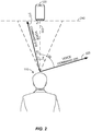
- FIG. 2 illustrates directions of departure 212 and 222 for voice commands 210 and 220, respectively, which are spoken by the user 110 and received by a sound sensor in the electronic device 120, according to one embodiment of the present disclosure.
- the user 110 may speak voice commands 210 and 220 in different directions at different times and the voice commands 210 and 220 may be detected as speech by the electronic device 120.
- the direction of departure 212 of the voice command 210 from the user 110 may be toward the electronic device 120 while the direction of departure 222 of the voice command 220 may be in another direction away from the electronic device 120.
- the electronic device 120 may be configured to determine that a direction of departure of speech is toward itself when the direction is determined to be within a specified angle or range from a line between the electronic device 120 and the user 110.
- the specified angle or range may be ⁇ degrees from a reference line 230 between the user 110 and the electronic device 120. If an angle between a direction of departure of speech and the reference line 230 is less than or equal to ⁇ degrees, the electronic device 120 may determine that the direction of departure of the speech is toward itself.
- the electronic device 120 may detect the voice command 210 as speech and determine that the angle ⁇ 1 between the direction of departure 212 of the speech and the reference line 230 is less than ⁇ degrees. In this case, the electronic device 120 may determine that the direction of departure 212 of the speech is toward itself and recognize the voice command 210 in the speech to perform a function associated with the voice command 210.
- the electronic device 120 may detect the voice command 220 as speech and determine that the angle ⁇ 2 between the direction of departure 222 of the speech and the reference line 230 is greater than ⁇ degrees. In this case, the electronic device 120 may determine that the direction of departure 222 of the speech is not toward itself so that the voice command 220 is not processed. Thus, based on a direction of departure (DOD) of speech from the user 110, the electronic device 120 may determine whether the speech is spoken in a direction toward the electronic device even when the user 110 speaks in different directions in a same location. In one embodiment, the electronic device 120 may determine a direction of departure of speech by using a single sound sensor (e.g., microphone) or any number of sound sensors.
- a single sound sensor e.g., microphone
- a direction of departure of speech is different from "a direction of arrival” (DOA), which refers to an arrival angle of speech spoken by a user.
- DOA direction of arrival
- the electronic device 120 may determine that the direction of arrival of the voice command 210 in the electronic device 120 is a direction defined by the reference line 230.
- the electronic device 120 may determine that the direction of arrival of the voice command 220 in the electronic device 120 is a direction defined by the reference line 230, even when the voice command 220 is spoken in a direction away from the electronic device 120.
- the direction of arrival 230 of the voice commands 210 and 220 in the electronic device 120 is ⁇ degrees away from a reference line 240, which may be defined as a line between a pair of sound sensors (e.g., a pair of microphones). Since the directions of arrival 230 are determined to be the same for the voice commands 210 and 220 that are spoken in different directions, the electronic device 120 may use a direction of arrival (DOA) for determining in which direction the source of sound is located with reference to the reference line 240 and use a direction of departure for determining whether speech is spoken in a direction toward the electronic device 120.
- DOA direction of arrival
- any other electronic device such as electronic device 130, 140, or 150 may be configured to determine whether speech from a user (e.g., the user 110) is spoken in a direction toward itself in a similar manner as the electronic device 120.
- FIG. 3 illustrates a voice command 310 spoken by the user 110 in a direction of departure 312 and received by one or more sound sensors in each of the electronic devices 120 and 130, according to one embodiment of the present disclosure.
- the user 110 may be located near the electronic devices 120 and 130, and speak the voice command 310 toward the electronic device 120. As shown, a distance D1 between the user 110 and the electronic device 120 may be greater than a distance D2 between the user 110 and the electronic device 130.
- each of the electronic devices 120 and 130 may detect the voice command 310 as speech and calculate a ratio between first characteristics of a first frequency range (e.g., an energy value of a high frequency band) and second characteristics of a second frequency range (e.g., an energy value of a low frequency band) of the speech.
- first characteristics of a first frequency range e.g., an energy value of a high frequency band
- second characteristics of a second frequency range e.g., an energy value of a low frequency band
- each of the electronic devices 120 and 130 may determine a spectral flatness value of a high frequency range of the speech based on first characteristics of a first frequency range (e.g., energy values of a high frequency band) and second characteristics of a second frequency range (e.g., an energy value of a low frequency band) of the speech.
- each of the electronic devices 120 and 130 may determine whether the direction of departure 312 of the voice command 310 is toward itself. Since a signal intensity of speech received by the electronic device 120 or 130 may vary depending on a distance (e.g., D1 or D2) from the user 110, the electronic device 120 or 130 may use the ratio between the first characteristics and the second characteristics of the speech or the spectral flatness value of the high frequency range of the speech as a normalized value which is independent of a distance from the user 110. Accordingly, the ratio or the spectral flatness value calculated by the electronic device 120 or 130 may be independent of a signal intensity of input sound received from the user 110.
- a distance e.g., D1 or D2
- each of the electronic devices 120 and 130 may detect the voice command 310 as speech and determine whether the direction of departure 312 of the speech is toward itself independent of the distance D1 or D2 from the sound source (e.g., the user 110). For example, the electronic device 120 may detect the voice command 310 as speech and determine that the direction of departure 312 of the speech is toward itself based on a ratio between energy values of high and low frequency bands of the speech or a spectral flatness value of a high frequency band. In one embodiment, the electronic device 120 may determine that the direction of departure 312 of the speech is toward itself when the ratio is greater than or equal to a threshold value or when the spectral flatness value is less than or equal to a threshold value. Upon determining that the direction of departure 312 of the speech is toward itself, the electronic device 120 may recognize the voice command 310 in the speech and perform a function associated with the voice command 310.
- the electronic device 130 which is located closer to the user 110 than the electronic device 120, may detect the voice command 310 as speech and determine that the direction of departure 312 of the speech is not toward itself based on a ratio between energy values of high and low frequency bands of the speech or a spectral flatness value of a high frequency band.
- the sound intensity of speech received by the electronic device 130 may be greater than that of the electronic device 120 since the distance D1 is greater than the distance D2, the electronic device 130 may determine that the direction of departure 312 of the speech is not toward itself based on the ratio or the spectral flatness value so that the voice command 310 is not processed.
- FIG. 4 illustrates a block diagram of the electronic device 120 configured to determine whether a direction of departure of speech is toward itself and perform a function associated with a voice command in the speech, according to one embodiment of the present disclosure.
- the electronic device 120 may include a sound sensor 420, a processor 430, an I/O unit 440, a storage unit 450, and a communication unit 460.
- the processor 430 may include a speech detector 432, a frequency analyzing unit 434, a speech direction determining unit 436, and a speech recognition unit 438.
- the processor 430 may be any suitable processor for managing and operating the electronic device 120, such as an application processor (AP), central processing unit (CPU), digital signal processor (DSP), etc.
- AP application processor
- CPU central processing unit
- DSP digital signal processor
- the electronic device 120 may be any suitable device equipped with sound capturing and processing capabilities such as a cellular phone, a smartphone, a laptop computer, a wearable computer, a tablet computer, a gaming device, a multimedia player, a smart TV, a voice-controlled lighting device, etc.
- the sound sensor 420 may be configured to continuously, periodically, or intermittently receive an input sound 410 and provide the received input sound 410 to the speech detector 432.
- the sound sensor 420 may receive at least a portion of speech including a voice command from a user as the input sound 410 and provide the input sound 410 to the speech detector 432.
- the sound sensor 420 may include one or more microphones or any other types of sound sensors that can be used to receive, capture, sense, and/or detect the input sound 410.
- the sound sensor 420 may employ any suitable software and/or hardware for performing such functions.
- the sound sensor 420 may be configured to periodically receive the input sound 410 according to a duty cycle to reduce power consumption. For example, the sound sensor 420 may be activated periodically on a 10% duty cycle. Given a period of 100 ms, the sound sensor 420 may thus be configured to operate in an "active state" for 10 ms and in an "idle state” for the next 90 ms.
- the sound sensor 420 may determine whether the portion of the input sound 410 is greater than a threshold sound intensity.
- the threshold sound intensity may be a predetermined threshold sound intensity. If the intensity of the portion of the input sound 410 is determined to be greater than the predetermined threshold sound intensity, the sound sensor 420 may activate the speech detector 432 in the processor 430 and provide the portion of the input sound 410 to the speech detector 432.
- the sound sensor 420 may receive the portion of the input sound 410 periodically during an active state of the duty cycle and automatically activate the speech detector 432 to provide the received portion to the speech detector 432. In another embodiment, the sound sensor 420 may continuously receive the input sound 410 and activate the speech detector 432 to provide the received input sound 410 to the speech detector 432.
- the speech detector 432 in the processor 330 may receive at least the portion of the input sound 410 from the sound sensor 420.
- the speech detector 432 may then extract a plurality of sound features from at least the portion of the input sound 410 and determine whether the extracted sound features are indicative of a sound of interest such as speech by using any suitable sound classification methods such as a Gaussian mixture model (GMM) based classifier, a neural network, a Hidden Markov model (HMM), a graphical model, a Support Vector Machine (SVM), and the like.
- GMM Gaussian mixture model
- HMM Hidden Markov model
- SVM Support Vector Machine
- the speech detector 432 may receive a remaining portion of the input sound 410 via the sound sensor 420.
- the speech detector 432 may activate the frequency analyzing unit 434 and provide the input sound 410 to the frequency analyzing unit 434.
- the frequency analyzing unit 434 may be configured to analyze characteristics of the speech received from the user as the input sound 410.
- the frequency analyzing unit 434 may determine first characteristics of a first frequency range (e.g., first frequency band) and second characteristics of a second frequency range (e.g., second frequency band) of the speech (i.e., input sound 410).
- first frequency range e.g., first frequency band
- second frequency range e.g., second frequency band
- the first frequency range may be higher than the second frequency range and the first and second frequency ranges may include at least one frequency.
- the first and second characteristics may be values or parameters such as energy values, spectral moments (for example, mean, variance, skewness, and kurtosis), spectral flatness, spectral centroid, crest factor, spectral slope, spectral roll-off, F0 contour, etc. that may characterize the associated frequency range in the speech received from the user.
- the frequency analyzing unit 434 may calculate a ratio between the first and second characteristics.
- the frequency analyzing unit 434 may convert the input sound 410 from the time domain into the frequency domain or the time-frequency domain, and calculate a ratio between an energy value of a high frequency range (e.g., 10 kHz to 15 kHz) and an energy value of a low frequency range (e.g., 0 kHZ to 5 kHz).
- the frequency analyzing unit 434 may calculate a spectral flatness value of a high frequency range of the speech using Equation 1 above.
- the frequency analyzing unit 434 may provide the calculated ratio or the spectral flatness value to the speech direction determining unit 436.
- the ratio or the spectral flatness value may be indicative of a probability that the direction of departure of the user's speech is toward the electronic device 120.
- the speech direction determining unit 436 may determine whether a direction of departure of the speech is toward itself based on the ratio or the spectral flatness value. In one embodiment, the speech direction determining unit 436 may determine that a direction of departure of the speech is toward the electronic device 120 when the ratio is greater than or equal to a threshold value or when the spectral flatness value is less than or equal to a threshold value. In a particular embodiment, the threshold value may be a predetermined threshold value.
- the frequency analyzing unit 434 may use the ratio between the energy value of the high frequency range and the energy value of the low frequency range or the spectral flatness value of the high frequency range to determine whether the direction of departure of the speech is toward the electronic device.
- the input sound 410 may be provided to the speech recognition unit 438 to perform speech recognition on the speech.
- the speech recognition unit 438 may then recognize the voice command in the speech (i.e., input sound 410).
- the speech recognition unit 438 may access language models, acoustic models, grammar models, or the like from the storage unit 450 for use in recognizing speech and/or voice commands of one or more users.
- the storage unit 450 may be remote or local storage, and may be implemented using any suitable storage or memory devices such as a RAM (Random Access Memory), a ROM (Read-Only Memory), an EEPROM (Electrically Erasable Programmable Read-Only Memory), a flash memory, or an SSD (solid state drive).
- the processor 430 may perform a function associate with the voice command and show the result thereof to the user via the I/O unit 440.
- any other electronic device such as electronic device 130, 140, or 150 may be configured to determine whether speech from a user is spoken in a direction toward itself in a similar manner as the electronic device 120.
- the electronic device 120 may be configured to communicate with an external device (e.g., the electronic devices 120 to 150 in FIG. 1 or a server) via the communication unit 460. In this case, the electronic device 120 may send the calculated ratio or the spectral flatness value to the external device via the communication unit 460. The electronic device 120 may also receive a ratio or a spectral flatness value from the external device as an indication of a spoken direction of the speech via the communication unit 460. Upon comparing the ratios or the spectral flatness values, the speech direction determining unit 436 may determine that the electronic device 120 is the intended target device for the speech if the electronic device 120 has the highest ratio or the lowest spectral flatness value. If it is determined that the electronic device 120 has the highest ratio or the lowest spectral flatness value, the speech recognition unit 438 may recognize the voice command in the speech (i.e., input sound 410) to perform a function associated with the voice command.
- an external device e.g., the electronic devices 120 to 150 in FIG. 1 or
- the electronic device 120 may receive a message from the external device (e.g., a server) indicating that it is the intended target device for the voice command.
- the speech recognition unit 438 may recognize the voice command in the speech (i.e., input sound 410).
- the processor 430 may then perform a function associated with the recognized voice command.
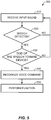
- FIG. 5 illustrates a flowchart of an exemplary method 500 for controlling an electronic device in response to speech spoken by a user, according to one embodiment of the present disclosure.
- the electronic device e.g., one of the electronic devices 120 to 150 in FIG. 1
- the electronic device may determine whether speech is detected in the received input sound.
- the electronic device may detect speech by using any methods such as a Gaussian mixture model (GMM) based classifier, a neural network, a Hidden Markov model (HMM), a graphical model, a Support Vector Machine (SVM), and the like. If speech is not detected (i.e., NO at 520), the method 500 may proceed back to 510 and receive another input sound via the sound sensor.
- GMM Gaussian mixture model
- HMM Hidden Markov model
- SVM Support Vector Machine
- the electronic device may determine a direction of departure (DOD) of the speech and determine whether the direction of departure (DOD) of the speech is toward itself at 530. If the electronic device determines that the direction of departure (DOD) of the speech is not toward itself (i.e., NO at 530), the method 500 may proceed back to 510 and receive another input sound via the sound sensor. On the other hand, if the electronic device determines that the direction of departure (DOD) of the speech is toward itself (i.e., YES at 530), the electronic device may recognize the voice command in the speech at 540.
- DOD direction of departure
- the electronic device may perform a function associated with the voice command at 550.
- Some embodiments of the present disclosure that determine a ratio between first characteristics of a first frequency range and second characteristics of a second frequency range of a speech are described below with reference to FIGs. 6 to 10 . As described above, such embodiments may determine a spectral flatness value of a high frequency range of a speech instead of or in addition to determining a ratio between first characteristics of a first frequency range and second characteristics of a second frequency range of a speech.
- FIG. 6 illustrates a flowchart of an exemplary method 530 performed in an electronic device for determining whether a direction of departure (DOD) of speech received from a user is toward itself, according to one embodiment of the present disclosure.
- the electronic device may determine first characteristics of a first frequency range and second characteristics of a second frequency range of the speech at 610 and 620, respectively.
- the first frequency range may be higher than the second frequency range and the first and second frequency ranges may include at least one frequency.
- the first and second characteristics may be values or parameters such as energy values, spectral moments (for example, mean, variance, skewness, and kurtosis), spectral flatness, spectral centroid, crest factor, spectral slope, spectral roll-off, F0 contour, etc. that may characterize the associated frequency range in the speech received from the user.
- the electronic device may determine a ratio between the first characteristics of the first frequency range and the second characteristics of the second frequency range of the speech. For example, the electronic device may calculate a ratio between an energy value of a high frequency range and an energy value of a low frequency range of the speech. Upon determining the ratio, the electronic device may determine whether the ratio is greater than or equal to a threshold value, which may be a predetermined value, at 640. In one embodiment, an optimal value for reducing a false alarm and enhancing accuracy of detection may be determined and set as the threshold value.
- the electronic device may determine that the direction of departure of the speech is toward itself and the method 530 may proceed to the method 540 in FIG. 5 to recognize a voice command in the speech.
- the electronic device may determine that the direction of departure of the speech is not toward itself and the method 530 may proceed to the method 510 in FIG. 5 to receive another input sound via the sound sensor.
- FIG. 7 illustrates a flowchart of an exemplary method 700 for controlling an electronic device in response to speech spoken by a user in connection with other electronic devices, according to one embodiment of the present disclosure.
- the electronic device e.g., one of the electronic devices 120 to 150 in FIG. 1
- the electronic device may determine whether speech is detected in the received input sound.
- the electronic device may detect speech by using any methods such as a Gaussian mixture model (GMM) based classifier, a neural network, a Hidden Markov model (HMM), a graphical model, a Support Vector Machine (SVM), and the like. If speech is not detected (i.e., NO at 720), the method 700 may proceed back to 710 to receive another input sound via the sound sensor.
- GMM Gaussian mixture model
- HMM Hidden Markov model
- SVM Support Vector Machine
- the electronic device may determine a direction of departure (DOD) of the speech at 730. In one embodiment, the electronic device may calculate a ratio between an energy value of a high frequency range and an energy value of a low frequency range of the speech. At 740, the electronic device may then determine whether a direction of departure (DOD) of the speech is toward itself at 740. In one embodiment, the electronic device may determine that the direction of departure of the speech is toward itself when the ratio between the energy value of the high frequency range and the energy value of the low frequency range of the speech is greater than or equal to a threshold value, which may be a predetermined value. If the electronic device determines that the direction of departure (DOD) of the speech is not toward itself (i.e., NO at 740), the method 700 may proceed back to 710 to receive another input sound via the sound sensor.
- DOD direction of departure
- the electronic device may receive at least one indication of a spoken direction of the speech from external devices at 750.
- the indication of the spoken direction of the speech may be a ratio between an energy value of a high frequency range and an energy value of a low frequency range of speech received at an external device.
- the electronic device may determine whether it is the intended target of the speech based on the calculated ratio and the at least one indication received from other external devices. For example, the electronic device may compare the calculated ratio with the ratios received from the other devices and determine that it is the target of the speech when the calculated ratio has the highest value.
- the method 700 may proceed back to 710 to receive another input sound via the sound sensor.
- the electronic device may recognize the voice command in the speech at 770. Once the voice command in the speech is recognized, the electronic device may perform a function associated with the voice command at 780. In another embodiment, the electronic device may omit performing the step of 740.
- the electronic device may directly proceed to receive at least one indication of a spoken direction of the speech from external devices at 750 after determining a direction of departure (DOD) of the speech (e.g., calculating a ratio between an energy value of a high frequency range and an energy value of a low frequency range of the speech) at 730.
- DOD direction of departure
- FIG. 8 illustrates an exemplary graph 800 that may be generated by an electronic device by plotting energy values of a received input sound at a specified time as a function of frequency, according to one embodiment of the present disclosure.
- the horizontal axis of the graph 800 may represent a frequency range starting from 0 Hz and the vertical axis may represent a range of energy values of the input sound.
- a signal intensity of the input sound at a specified frequency may be represented as an energy value.
- the frequency range in the graph 800 may be divided into a plurality of frequency ranges 810 to 880 (e.g., frequency bands), each having a width of 2.5 kHz.
- the plurality of frequency ranges 810 to 880 may have different widths.
- the electronic device may receive a user's speech including a voice command at a particular time as an input sound via a sound sensor.
- the intensities of the received sound associated with a frequency range may then be converted into energy values.
- the energy values may be plotted in the graph 800 as a function of frequency.
- the electronic device may select a low frequency range 810 and a high frequency range 850.
- the graph 800 is illustrated with the low and high frequency ranges 810 and 850 that are selected, any number of frequency ranges may be selected for the low frequency range or the high frequency range.
- An energy value for each of the low frequency range 810 and the high frequency range 850 may be obtained by integrating the energy values within the frequency range.
- the electronic device may then calculate a ratio between the energy values for the high and low frequency ranges 850 and 810, respectively. Since the ratio is based on the energy values for the high and low frequency ranges 850 and 810, respectively, which may have different directional propagation characteristics, the ratio may be indicative of a probability that a direction of departure of the user's speech is toward the electronic device.
- the electronic device may be configured to determine that the direction of departure of the user's speech is toward itself when the ratio is greater than or equal to a threshold value, which may be a predetermined value.
- a threshold value which may be a predetermined value.
- an optimal value for reducing false alarm and enhancing accuracy of detection may be determined and set as the threshold value.
- the threshold value may be set as 0.5.
- the ratio between the energy values of the high and low frequency ranges 850 and 810, respectively may be determined to be 0.6, as shown in the graph 800. Since the ratio is greater than or equal to the threshold value, the electronic device may determine that the direction of departure of the user's speech is toward itself. On the other hand, if the ratio is determined to be less than the threshold value, the electronic device may determine that the direction of departure of the user's speech is not toward itself.
- the electronic device may receive a user's speech including a voice command for a specified time period as an input sound via the sound sensor.
- the input sound may be converted from a time domain to a time-frequency domain by using any suitable transformation or function such as the Fourier transform, etc.
- the electronic device may generate a three-dimensional graph that plots energy values associated with the received input sound as a function of frequency and time.
- the three-dimensional graph may include any suitable number of two-dimensional graphs (e.g., the graph 800) along the time axis.
- An energy value for a low frequency range and an energy value for a high frequency range may be obtained by integrating the energy values within the frequency range during the specified time period.
- the electronic device may then calculate a ratio between the energy values for the high and low frequency ranges and determine whether the direction of departure of the user's speech is toward itself in a similar manner as described with reference to the graph 800.
- FIG. 9 illustrates the plurality of electronic devices 120 to 150 configured to communicate with a server 920 via a communication network 910 for determining an intended target of a speech spoken by the user 110, according to one embodiment of the present disclosure.
- the electronic devices 120 to 150 are a smartphone, a tablet computer, a smart TV, and a voice-controlled lighting device, respectively, and may be located in a room 900.
- the electronic devices 120 to 150 are shown in the room 900, any number of electronic devices may be located in the room 900 or any other suitable location in proximity to the user 110.
- the user 110 may speak a voice command in a direction toward the electronic device 130 to activate the electronic device 130 or instruct the electronic device 120 to perform a function.
- each of the electronic devices 120 to 150 may receive the voice command as an input sound and detect speech in the input sound.
- each of the electronic devices 120 to 150 may calculate a ratio between first characteristics of a first frequency range (e.g., an energy value of a high frequency range) and second characteristics of a second frequency range (e.g., an energy value of a low frequency range) of the speech.
- the calculated ratios may then be sent to the server 920 via the communication network 910.
- the communication network 910 may be a wired network or a wireless network.
- the server 920 may compare the ratios received from the electronic devices 120 to 150 and determine that the electronic device having the highest ratio is the intended target device for the voice command.
- the server 920 may be configured to compare the highest ratio with a threshold value, which may be a predetermined value.
- the threshold value may be determined as an optimal value for reducing a false alarm and enhancing accuracy of detection.
- the server 920 may determine that the electronic device having the highest ratio is the intended target device for the voice command.
- the server 920 may determine that none of the electronic devices are the intended target device for the voice command.
- the server 920 may determine that the ratio received from the electronic device 130 is the highest ratio among the ratios received from the electronic devices 120 to 150 since the user has spoken the voice command in a direction toward the electronic device 130. In response, the server 920 may send a message to the electronic device 130 indicating that it is the intended target device for the voice command. Upon receiving the message, the electronic device 130 may proceed to recognize the voice command and perform a function associated with the voice command.
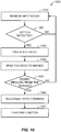
- FIG. 10 illustrates a flowchart of an exemplary method 1000 for controlling an electronic device in response to speech spoken by a user in connection with a server, according to one embodiment of the present disclosure.
- the electronic device e.g., one of the electronic devices 120 to 150 in FIG. 1
- the electronic device may determine whether speech is detected in the received input sound.
- the electronic device may detect speech by using any methods such as a Gaussian mixture model (GMM) based classifier, a neural network, a Hidden Markov model (HMM), a graphical model, a Support Vector Machine (SVM), and the like. If speech is not detected (i.e., NO at 1020), the method 1000 may proceed back to 1010 to receive another input sound via the sound sensor.
- GMM Gaussian mixture model
- HMM Hidden Markov model
- SVM Support Vector Machine
- the electronic device may calculate a ratio between first characteristics of a first frequency range (e.g., an energy value of a high frequency range) and second characteristics of a second frequency range (e.g., an energy value of a low frequency range) of the speech at 1030.
- the calculated ratio may be indicative of a probability that the direction of departure of the speech is toward itself.
- the electronic device may send the calculated ratio to a server.
- the electronic device may determine whether a message indicating that it is the intended target device of the voice command is received from the server within a specified time period at 1050. If the electronic device does not receive the signal from the server during the specified time period, the method 1000 may proceed back to 1010 to receive another input sound via the sound sensor. On the other hand, if the electronic device receives the signal from the server within the specified period, the electronic device may recognize the voice command in the speech at 1060. Once the voice command in the speech is recognized, the electronic device may perform a function associated with the voice command at 1070.
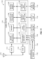
- FIG. 11 illustrates a block diagram of an electronic device 1100 in which the methods and apparatus of the present disclosure for controlling an electronic device in response to speech spoken by a user may be implemented according to some embodiments.
- the electronic device 1100 may be a cellular phone, a smartphone, a wearable computer, a smart watch, smart glasses, a tablet personal computer, a terminal, a handset, a personal digital assistant (PDA), a wireless modem, a cordless phone, a tablet, and so on.
- the wireless communication system may be a CDMA system, a GSM system, a W-CDMA system, a LTE system, a LTE Advanced system, and so on.
- the electronic device 1100 may be capable of providing bidirectional communication via a receive path and a transmit path.
- signals transmitted by base stations may be received by an antenna 1112 and may be provided to a receiver (RCVR) 1114.
- the receiver 1114 may condition and digitize the received signal, and provide the conditioned and digitized digital signal to a digital section for further processing.
- a transmitter (TMTR) 1116 may receive data to be transmitted from a digital section 1120, process and condition the data, and generate a modulated signal, which is transmitted via the antenna 1112 to the base stations.
- the receiver 1114 and the transmitter 1116 may be part of a transceiver that may support CDMA, GSM, W-CDMA, LTE, LTE Advanced, and so on.
- the digital section 1120 may include various processing, interface, and memory units such as, for example, a modem processor 1122, a reduced instruction set computer/digital signal processor (RISC/DSP) 1124, a controller/processor 1126, an internal memory 1128, a generalized audio/video encoder 1132, a generalized audio decoder 1134, a graphics/display processor 1136, and an external bus interface (EBI) 1138.
- the modem processor 1122 may perform processing for data transmission and reception, e.g., encoding, modulation, demodulation, and decoding.
- the RISC/DSP 1124 may perform general and specialized processing for the electronic device 1100.
- the controller/processor 1126 may perform the operation of various processing and interface units within the digital section 1120.
- the internal memory 1128 may store data and/or instructions for various units within the digital section 1120.
- the generalized audio/video encoder 1132 may perform encoding for input signals from an audio/video source 1142, a microphone 1144, an image sensor 1146, etc.
- the generalized audio decoder 1134 may perform decoding for coded audio data and may provide output signals to a speaker/headset 1148.
- the graphics/display processor 1136 may perform processing for graphics, videos, images, and texts, which may be presented to a display unit 1150.
- the EBI 1138 may facilitate transfer of data between the digital section 1120 and a main memory 1152.
- the digital section 1120 may be implemented with one or more processors, DSPs, microprocessors, RISCs, etc.
- the digital section 1120 may also be fabricated on one or more application specific integrated circuits (ASICs) and/or some other type of integrated circuits (ICs).
- ASICs application specific integrated circuits
- ICs integrated circuits
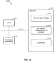
- FIG. 12 is a block diagram illustrating a server system 1200, which may be any one of the servers previously described implemented according to some embodiments.
- the server system 1200 may include one or more processing units (e.g., CPUs) 1202, one or more network or other communications network interfaces, a memory 1212, and one or more communication buses 1214 for interconnecting these components.
- the server system 1200 may also include a user interface (not shown) having a display device and a keyboard.
- the memory 1212 may be any suitable memory, such as a high-speed random access memory, (e.g., DRAM, SRAM, DDR RAM or other random access solid state memory devices).
- the memory 1212 may include or may alternatively be non-volatile memory (e.g., one or more magnetic disk storage devices, optical disk storage devices, flash memory devices, or other non-volatile solid state storage devices).
- the memory 1212 may include one or more storage devices remotely located from the CPU(s) 1202 and/or remotely located in multiple sites.
- any one of the above memory devices represented by the memory 1212 may store any number of modules or programs that corresponds to a set of instructions for performing and/or executing any of the processes, operations, and methods previously described.
- the memory 1212 may include an operating system 1216 configured to store instructions that includes procedures for handling various basic system services and for performing hardware dependent tasks.
- a network communication module 1218 of the memory 1212 may be used for connecting the server system 1200 to other computers via the one or more communication network interfaces 1210 (wired or wireless) and one or more communication networks, such as the Internet, other wide area networks, local area networks, metropolitan area networks, and so on.
- the memory 1212 may also include a database 1220 configured to include language models, acoustic models, grammar models, or the like. Each of the models the database may be used for recognizing speech and/or commands of one or more users.
- the operating system 1216 may update the database 1220 through the network communication module 1218.
- the operating system 1216 may also provide a message indicating that an electronic device is an intended target device for a voice command via the network communication module 1218.
- any device described herein may represent various types of devices, such as a wireless phone, a cellular phone, a laptop computer, a wireless multimedia device, a wireless communication personal computer (PC) card, a PDA, an external or internal modem, a device that communicates through a wireless channel, etc.
- a device may have various names, such as access terminal (AT), access unit, subscriber unit, mobile station, mobile device, mobile unit, mobile phone, mobile, remote station, remote terminal, remote unit, user device, user equipment, handheld device, etc.
- Any device described herein may have a memory for storing instructions and data, as well as hardware, software, firmware, or combinations thereof.
- processing units used to perform the techniques may be implemented within one or more ASICs, DSPs, digital signal processing devices (DSPDs), programmable logic devices (PLDs), field programmable gate arrays (FPGAs), processors, controllers, micro-controllers, microprocessors, electronic devices, other electronic units designed to perform the functions described herein, a computer, or a combination thereof.
- ASICs application specific integrated circuits
- DSPs digital signal processing devices
- DSPDs digital signal processing devices
- PLDs programmable logic devices
- FPGAs field programmable gate arrays
- processors controllers, micro-controllers, microprocessors, electronic devices, other electronic units designed to perform the functions described herein, a computer, or a combination thereof.
- a general-purpose processor may be a microprocessor, but in the alternate, the processor may be any processor, controller, microcontroller, or state machine.
- a processor may also be implemented as a combination of computing devices, e.g., a combination of a DSP and a microprocessor, a plurality of microprocessors, one or more microprocessors in conjunction with a DSP core, or any other such configuration.
- Computer-readable media include both computer storage media and communication media including any medium that facilitates the transfer of a computer program from one place to another.
- a storage media may be any available media that can be accessed by a computer.
- such computer-readable media can comprise RAM, ROM, EEPROM, CD-ROM or other optical disk storage, magnetic disk storage or other magnetic storage devices, or any other medium that can be used to carry or store desired program code in the form of instructions or data structures and that can be accessed by a computer.
- Disk and disc includes compact disc (CD), laser disc, optical disc, digital versatile disc (DVD), floppy disk and Blu-ray disc, where disks usually reproduce data magnetically, while discs reproduce data optically with lasers. Combinations of the above should also be included within the scope of computer-readable media.
- a computer-readable storage medium may be a non-transitory computer-readable storage device that includes instructions that are executable by a processor. Thus, a computer-readable storage medium may not be a signal.
- aspects of the presently disclosed subject matter may be implemented in or across a plurality of processing chips or devices, and storage may similarly be affected across a plurality of devices.
- Such devices may include PCs, network servers, and handheld devices.
- modules or programs i.e., sets of instructions
- the memory 1212 may store additional modules and data structures not described above.
Description
- The present disclosure relates generally to controlling electronic devices, and more specifically, to controlling electronic devices in response to speech spoken by a user.
- Recently, the use of electronic devices such as smartphones, tablet computers, smart TVs, and the like has become widespread. These devices often provide voice and/or data communication functionalities over wireless or wired networks. In addition, such devices may provide a variety of functions designed to enhance user convenience such as sound processing, image or video processing, navigation, reproduction of music or multimedia files, etc.
- Among such functions, conventional electronic devices are often equipped with a speech recognition function. Such electronic devices may perform a function in response to receiving and recognizing a voice command from a user. For example, an electronic device equipped with a speech recognition function may activate an application, play an audio file, or take a picture in response to a voice command from a user.
- Due to the widespread use of electronic devices, users often have access to a plurality of electronic devices equipped with a speech recognition function that are located near each other. For example, a user may be in a living room in which his or her smartphone, tablet computer, and smart TV are located. In such a case, if the user speaks a voice command toward the smartphone as the intended target, the tablet computer and smart TV as well as the smartphone may receive and respond to the voice command. Thus, such electronic devices may not be able to accurately determine whether they are the intended target of a voice command for responding to the voice command.
- United States Patent No.
7,167,544 B1 describes a telecommunication system which provides error messages corresponding to speech recognition errors. At least one voice parameter is analyzed during a voice recognition process. If the voice parameter exceeds a threshold, a message is delivered to the user. The message prompts the user to re-input the command with a correction which has been adjusted to the voice parameter. - European Patent Application with publication no.
EP 2509070 A1 describes techniques in which audio or visual orientation cues are used to determine the relevance of input speech. In some cases, orientation characteristics for input sound can be determined. A relevance of the user's speech during an interval of time may be characterized based on the one or more orientation characteristics. - The scope of protection is defined by the independent claims. Optional features are included in the dependent claims.
- The present disclosure provides methods and apparatus for controlling an electronic device in response to speech spoken by a user.
- According to one aspect of the present invention, there is provided a method for controlling an electronic device in response to speech spoken by a user according to claim 1. According to another aspect of the present invention, there is provided an electronic device according to claim 7. According to another aspect of the present invention there is provided a non-transitory computer-readable storage medium according to claim 13.
- In line with the indication previously provided, that the invention is set forth in the independent claims, all following occurrences of the word "embodiment(s) [of this / the present disclosure]", if referring to feature combinations different from those defined by the independent claims, refer to examples which were originally filed but which do not represent embodiments of the presently claimed invention, which examples are still shown for illustrative purposes only.
- Embodiments of this disclosure will be understood with reference to the following detailed description, when read in conjunction with the accompanying drawings.
-
FIG. 1 illustrates electronic devices configured to detect speech spoken by a user and perform a function based on a direction of departure of the speech, according to one embodiment of the present disclosure. -
FIG. 2 illustrates directions of departure for voice commands, which are spoken by a user and received by a sound sensor in an electronic device, according to one embodiment of the present disclosure. -
FIG. 3 illustrates a voice command spoken by a user in a direction of departure and received by one or more sound sensors in each of electronic devices, according to one embodiment of the present disclosure. -
FIG. 4 illustrates a block diagram of an electronic device configured to determine whether a direction of departure of speech is toward itself and perform a function associated with a voice command in the speech, according to one embodiment of the present disclosure. -
FIG. 5 illustrates a flowchart of an exemplary method for controlling an electronic device in response to speech spoken by a user, according to one embodiment of the present disclosure. -
FIG. 6 illustrates a flowchart of an exemplary method performed in an electronic device for determining whether a direction of departure (DOD) of speech received from a user is toward itself, according to one embodiment of the present disclosure. -
FIG. 7 illustrates a flowchart of an exemplary method for controlling an electronic device in response to speech spoken by a user in connection with other electronic devices, according to one embodiment of the present disclosure. -
FIG. 8 illustrates an exemplary graph that may be generated by an electronic device by plotting energy values of a received input sound at a specified time as a function of frequency, according to one embodiment of the present disclosure. -
FIG. 9 illustrates a plurality of electronic devices configured to communicate with aserver 920 via a communication network for determining an intended target of a speech spoken by a user, according to one embodiment of the present disclosure. -
FIG. 10 illustrates a flowchart of an exemplary method for controlling an electronic device in response to speech spoken by a user in connection with a server, according to one embodiment of the present disclosure. -
FIG. 11 illustrates a block diagram of an electronic device in which the methods and apparatus of the present disclosure for controlling an electronic device in response to speech spoken by a user may be implemented according to some embodiments. -
FIG. 12 is a block diagram illustrating a server system, which may be any one of the servers previously described implemented according to some embodiments. - Reference will now be made in detail to various embodiments, examples of which are illustrated in the accompanying drawings. In the following detailed description, numerous specific details are set forth in order to provide a thorough understanding of the present subject matter. However, it will be apparent to one of ordinary skill in the art that the present subject matter may be practiced without these specific details. In other instances, well-known methods, procedures, systems, and components have not been described in detail so as not to unnecessarily obscure aspects of the various embodiments.
-
FIG. 1 illustrateselectronic devices 120 to 150 configured to detect speech spoken by auser 110 and perform a function based on a direction of departure of the speech, according to one embodiment of the present disclosure. Theelectronic devices 120 to 150 may be any suitable device equipped with sound capturing and processing capabilities such as a cellular phone, a smartphone, a laptop computer, a wearable computer, a tablet computer, a gaming device, a multimedia player, a smart TV, a voice-controlled lighting device, etc. In the illustrated embodiment, theelectronic devices 120 to 150 are a smartphone, a tablet computer, a smart TV, and a voice-controlled lighting device, respectively, and may be located in aroom 100. Although theelectronic devices 120 to 150 are shown in theroom 100, any number of electronic devices may be located in theroom 100 or any other suitable location in proximity to theuser 110. - The
user 110 may speak a voice command in a direction toward one of theelectronic devices 120 to 150 as a target device to control operation of the target device. As used herein, the phrase "a direction of departure toward an electronic device" or any variation thereof may refer to a direction along a line between a sound source (e.g., a user) and the electronic device, and may include any directions that deviate from the line within a specified angle or range. In the illustrated embodiment, theuser 110 may speak a voice command (e.g., "HI ASSISTANT") in a direction toward theelectronic device 120 to activate theelectronic device 120 or instruct theelectronic device 120 to perform a function (e.g., a voice assistant application 122). As used herein, the term "voice command" may refer to any speech or utterance including one or more words or sound that is indicative of a command or instruction to perform or activate a function or an application in theelectronic devices 120 to 150. - In response to a voice command, the
electronic devices 120 to 150 may perform a function or execute an application associated with the voice command based on a direction of departure of the voice command from theuser 110. For example, theelectronic device 120 may activate thevoice assistant application 122 upon determining that the direction of departure of the voice command "HI ASSISTANT" is toward itself. Based on a direction of departure of speech from a user, an electronic device may determine whether the speech spoken by the user is in a direction toward itself, as will be shown in more detail below. - The
electronic devices 120 to 150 may be configured to continuously, periodically, or intermittently receive an input sound via a sound sensor (e.g., microphone) and detect speech in the input sound. In the illustrated embodiment, theuser 110 may speak a voice command (e.g., "HI ASSISTANT") toward theelectronic device 120 to activate avoice assistant application 122 of theelectronic device 120. The user's speech including the voice command may be received by theelectronic devices 120 to 150 as an input sound. As the user's speech is being received as an input sound, theelectronic devices 120 to 150 may detect the speech in the input sound. - Once the speech is detected in the input sound, each of the
electronic devices 120 to 150 may determine whether a direction of departure of the speech (i.e., spoken direction of the speech) from theuser 110 is toward itself. As used herein, the phrase "determining whether a direction of departure of speech is toward itself" or any variation thereof may refer to determining whether a spoken direction of the speech is toward an electronic device, and may encompass either positive test (i.e., determining whether a spoken direction of the speech is toward an electronic device) or negative test (i.e., determining whether a spoken direction of the speech is not toward an electronic device). Among theelectronic devices 120 to 150, theelectronic device 120 may determine that the direction of departure of the speech is toward itself and proceed to activate thevoice assistant application 122 by recognizing the voice command (e.g., "HI ASSISTANT") in the speech. Each of the otherelectronic devices 130 to 150 may determine that the direction of departure of the speech is not toward itself so that the voice command is not processed. - For determining whether a direction of departure of speech is toward itself, each of the
electronic devices 120 to 150 may analyze characteristics of the speech received from theuser 110. In one embodiment, each of theelectronic devices 120 to 150 may determine first characteristics of a first frequency range (e.g., first frequency band) and second characteristics of a second frequency range (e.g., second frequency band) of the speech, and determine whether the direction of departure of the speech is toward itself based on the first and second characteristics. For example, the first frequency range may be higher than the second frequency range and the first and second frequency ranges may include at least one frequency. - The first and second characteristics may be values or parameters such as energy values, spectral moments (for example, mean, variance, skewness, and kurtosis), spectral flatness, spectral centroid, crest factor, spectral slope, spectral roll-off, F0 contour, etc. that may characterize the associated frequency range in the speech received from the
user 110. In an example that is not within the scope of the claims, each of theelectronic devices 120 to 150 may calculate a ratio between the first and second characteristics and determine that the direction of departure of the speech is toward itself based on the ratio. According to the claimed invention, theelectronic devices 120 to 150 determines a spectral flatness value based on the first and second characteristics and determine that the direction of departure of the speech is toward itself based on the spectral flatness value. The calculated ratio or the spectral flatness value may be indicative of a probability that the direction of departure of the speech is toward itself. - In a particular embodiment, each of the
electronic devices 120 to 150 may calculate a ratio between an energy value of a high frequency range and an energy value of a low frequency range of the speech, and determine that a direction of departure of the speech is toward itself when the ratio is greater than or equal to a threshold value, which may be a predetermined threshold value. Alternatively or additionally, each of theelectronic devices 120 to 150 may determine a spectral flatness value of a high frequency range of the speech according to the following equation:
electronic devices 120 to 150 may determine that a direction of departure of the speech is toward itself when the spectral flatness value is less than or equal to a threshold value, which may be a predetermined threshold value. - Since a low frequency signal or sound tends to propagate in all directions while a high frequency signal or sound is more directional in propagating mainly in a departure direction of the signal or sound, each of the
electronic devices 120 to 150 may use the ratio between the energy value of the high frequency range and the energy value of the low frequency range or the spectral flatness value of the high frequency range to determine whether the direction of departure of the speech is toward itself. In the illustrated embodiment, theelectronic device 120 may determine that the spoken direction of the speech is toward itself, and perform speech recognition on the speech to recognize a voice command (e.g., "HI ASSISTANT") in the speech. Once the voice command is recognized, theelectronic device 120 may activate thevoice assistant application 122 associate with the voice command (e.g., "HI ASSISTANT"). - In some embodiments, the
electronic devices 120 to 150 may be configured to communicate with each other via a wired or wireless network (not shown). In this case, each of theelectronic devices 120 to 150 may detect the speech spoken by theuser 110 and calculate a ratio between the first and second characteristics (e.g., energy values) of the speech or a spectral flatness value of a high frequency range of the speech. The calculated ratio or the spectral flatness value may then be sent to the other electronic devices. Upon comparing the ratios or the spectral flatness values of theelectronic devices 120 to 150, one of theelectronic devices 120 to 150 that has the highest ratio or the lowest spectral flatness value may determine that it is the intended target device for the speech. In response, the target electronic device may proceed to recognize the voice command in the speech and perform a function associated with the voice command. -
FIG. 2 illustrates directions ofdeparture user 110 and received by a sound sensor in theelectronic device 120, according to one embodiment of the present disclosure. Theuser 110 may speak voice commands 210 and 220 in different directions at different times and the voice commands 210 and 220 may be detected as speech by theelectronic device 120. As shown, the direction ofdeparture 212 of thevoice command 210 from theuser 110 may be toward theelectronic device 120 while the direction ofdeparture 222 of thevoice command 220 may be in another direction away from theelectronic device 120. - The
electronic device 120 may be configured to determine that a direction of departure of speech is toward itself when the direction is determined to be within a specified angle or range from a line between theelectronic device 120 and theuser 110. In the illustrated embodiment, the specified angle or range may be β degrees from areference line 230 between theuser 110 and theelectronic device 120. If an angle between a direction of departure of speech and thereference line 230 is less than or equal to β degrees, theelectronic device 120 may determine that the direction of departure of the speech is toward itself. For example, theelectronic device 120 may detect thevoice command 210 as speech and determine that the angle θ1 between the direction ofdeparture 212 of the speech and thereference line 230 is less than β degrees. In this case, theelectronic device 120 may determine that the direction ofdeparture 212 of the speech is toward itself and recognize thevoice command 210 in the speech to perform a function associated with thevoice command 210. - On the other hand, the
electronic device 120 may detect thevoice command 220 as speech and determine that the angle θ2 between the direction ofdeparture 222 of the speech and thereference line 230 is greater than β degrees. In this case, theelectronic device 120 may determine that the direction ofdeparture 222 of the speech is not toward itself so that thevoice command 220 is not processed. Thus, based on a direction of departure (DOD) of speech from theuser 110, theelectronic device 120 may determine whether the speech is spoken in a direction toward the electronic device even when theuser 110 speaks in different directions in a same location. In one embodiment, theelectronic device 120 may determine a direction of departure of speech by using a single sound sensor (e.g., microphone) or any number of sound sensors. - As used herein, a direction of departure of speech is different from "a direction of arrival" (DOA), which refers to an arrival angle of speech spoken by a user. If a direction of arrival (DOA) were to be used, the
electronic device 120 may determine that the direction of arrival of thevoice command 210 in theelectronic device 120 is a direction defined by thereference line 230. Similarly, theelectronic device 120 may determine that the direction of arrival of thevoice command 220 in theelectronic device 120 is a direction defined by thereference line 230, even when thevoice command 220 is spoken in a direction away from theelectronic device 120. In both cases, the direction ofarrival 230 of the voice commands 210 and 220 in theelectronic device 120 is α degrees away from areference line 240, which may be defined as a line between a pair of sound sensors (e.g., a pair of microphones). Since the directions ofarrival 230 are determined to be the same for the voice commands 210 and 220 that are spoken in different directions, theelectronic device 120 may use a direction of arrival (DOA) for determining in which direction the source of sound is located with reference to thereference line 240 and use a direction of departure for determining whether speech is spoken in a direction toward theelectronic device 120. Although theelectronic device 120 is shown inFIG. 2 , any other electronic device such aselectronic device electronic device 120. -
FIG. 3 illustrates avoice command 310 spoken by theuser 110 in a direction ofdeparture 312 and received by one or more sound sensors in each of theelectronic devices user 110 may be located near theelectronic devices voice command 310 toward theelectronic device 120. As shown, a distance D1 between theuser 110 and theelectronic device 120 may be greater than a distance D2 between theuser 110 and theelectronic device 130. - In one embodiment, each of the
electronic devices voice command 310 as speech and calculate a ratio between first characteristics of a first frequency range (e.g., an energy value of a high frequency band) and second characteristics of a second frequency range (e.g., an energy value of a low frequency band) of the speech. Alternatively or additionally, each of theelectronic devices electronic devices departure 312 of thevoice command 310 is toward itself. Since a signal intensity of speech received by theelectronic device user 110, theelectronic device user 110. Accordingly, the ratio or the spectral flatness value calculated by theelectronic device user 110. - According to the illustrated embodiment, each of the
electronic devices voice command 310 as speech and determine whether the direction ofdeparture 312 of the speech is toward itself independent of the distance D1 or D2 from the sound source (e.g., the user 110). For example, theelectronic device 120 may detect thevoice command 310 as speech and determine that the direction ofdeparture 312 of the speech is toward itself based on a ratio between energy values of high and low frequency bands of the speech or a spectral flatness value of a high frequency band. In one embodiment, theelectronic device 120 may determine that the direction ofdeparture 312 of the speech is toward itself when the ratio is greater than or equal to a threshold value or when the spectral flatness value is less than or equal to a threshold value. Upon determining that the direction ofdeparture 312 of the speech is toward itself, theelectronic device 120 may recognize thevoice command 310 in the speech and perform a function associated with thevoice command 310. - On the other hand, the
electronic device 130, which is located closer to theuser 110 than theelectronic device 120, may detect thevoice command 310 as speech and determine that the direction ofdeparture 312 of the speech is not toward itself based on a ratio between energy values of high and low frequency bands of the speech or a spectral flatness value of a high frequency band. Although the sound intensity of speech received by theelectronic device 130 may be greater than that of theelectronic device 120 since the distance D1 is greater than the distance D2, theelectronic device 130 may determine that the direction ofdeparture 312 of the speech is not toward itself based on the ratio or the spectral flatness value so that thevoice command 310 is not processed. -
FIG. 4 illustrates a block diagram of theelectronic device 120 configured to determine whether a direction of departure of speech is toward itself and perform a function associated with a voice command in the speech, according to one embodiment of the present disclosure. Theelectronic device 120 may include asound sensor 420, aprocessor 430, an I/O unit 440, astorage unit 450, and acommunication unit 460. As shown, theprocessor 430 may include aspeech detector 432, afrequency analyzing unit 434, a speechdirection determining unit 436, and aspeech recognition unit 438. Theprocessor 430 may be any suitable processor for managing and operating theelectronic device 120, such as an application processor (AP), central processing unit (CPU), digital signal processor (DSP), etc. Theelectronic device 120 may be any suitable device equipped with sound capturing and processing capabilities such as a cellular phone, a smartphone, a laptop computer, a wearable computer, a tablet computer, a gaming device, a multimedia player, a smart TV, a voice-controlled lighting device, etc. - The
sound sensor 420 may be configured to continuously, periodically, or intermittently receive aninput sound 410 and provide the receivedinput sound 410 to thespeech detector 432. For example, thesound sensor 420 may receive at least a portion of speech including a voice command from a user as theinput sound 410 and provide theinput sound 410 to thespeech detector 432. Thesound sensor 420 may include one or more microphones or any other types of sound sensors that can be used to receive, capture, sense, and/or detect theinput sound 410. In addition, thesound sensor 420 may employ any suitable software and/or hardware for performing such functions. - In some embodiments, the
sound sensor 420 may be configured to periodically receive theinput sound 410 according to a duty cycle to reduce power consumption. For example, thesound sensor 420 may be activated periodically on a 10% duty cycle. Given a period of 100 ms, thesound sensor 420 may thus be configured to operate in an "active state" for 10 ms and in an "idle state" for the next 90 ms. - In this case, when a portion of the
input sound 410 is received during an active portion of the duty cycle, thesound sensor 420 may determine whether the portion of theinput sound 410 is greater than a threshold sound intensity. In a particular embodiment, the threshold sound intensity may be a predetermined threshold sound intensity. If the intensity of the portion of theinput sound 410 is determined to be greater than the predetermined threshold sound intensity, thesound sensor 420 may activate thespeech detector 432 in theprocessor 430 and provide the portion of theinput sound 410 to thespeech detector 432. Alternatively, without determining whether the received portion exceeds a threshold sound intensity, thesound sensor 420 may receive the portion of theinput sound 410 periodically during an active state of the duty cycle and automatically activate thespeech detector 432 to provide the received portion to thespeech detector 432. In another embodiment, thesound sensor 420 may continuously receive theinput sound 410 and activate thespeech detector 432 to provide the receivedinput sound 410 to thespeech detector 432. - Upon being activated, the
speech detector 432 in the processor 330 may receive at least the portion of theinput sound 410 from thesound sensor 420. Thespeech detector 432 may then extract a plurality of sound features from at least the portion of theinput sound 410 and determine whether the extracted sound features are indicative of a sound of interest such as speech by using any suitable sound classification methods such as a Gaussian mixture model (GMM) based classifier, a neural network, a Hidden Markov model (HMM), a graphical model, a Support Vector Machine (SVM), and the like. If at least the portion of theinput sound 410 is determined to be a sound of interest (e.g., speech), thespeech detector 432 may receive a remaining portion of theinput sound 410 via thesound sensor 420. In addition, thespeech detector 432 may activate thefrequency analyzing unit 434 and provide theinput sound 410 to thefrequency analyzing unit 434. - The
frequency analyzing unit 434 may be configured to analyze characteristics of the speech received from the user as theinput sound 410. In one embodiment, thefrequency analyzing unit 434 may determine first characteristics of a first frequency range (e.g., first frequency band) and second characteristics of a second frequency range (e.g., second frequency band) of the speech (i.e., input sound 410). For example, the first frequency range may be higher than the second frequency range and the first and second frequency ranges may include at least one frequency. - According to one embodiment, the first and second characteristics may be values or parameters such as energy values, spectral moments (for example, mean, variance, skewness, and kurtosis), spectral flatness, spectral centroid, crest factor, spectral slope, spectral roll-off, F0 contour, etc. that may characterize the associated frequency range in the speech received from the user. In a particular embodiment, the
frequency analyzing unit 434 may calculate a ratio between the first and second characteristics. For example, thefrequency analyzing unit 434 may convert theinput sound 410 from the time domain into the frequency domain or the time-frequency domain, and calculate a ratio between an energy value of a high frequency range (e.g., 10 kHz to 15 kHz) and an energy value of a low frequency range (e.g., 0 kHZ to 5 kHz). Alternatively or additionally, thefrequency analyzing unit 434 may calculate a spectral flatness value of a high frequency range of the speech using Equation 1 above. Thefrequency analyzing unit 434 may provide the calculated ratio or the spectral flatness value to the speechdirection determining unit 436. The ratio or the spectral flatness value may be indicative of a probability that the direction of departure of the user's speech is toward theelectronic device 120. - Upon receiving the ratio or the spectral flatness value, the speech
direction determining unit 436 may determine whether a direction of departure of the speech is toward itself based on the ratio or the spectral flatness value. In one embodiment, the speechdirection determining unit 436 may determine that a direction of departure of the speech is toward theelectronic device 120 when the ratio is greater than or equal to a threshold value or when the spectral flatness value is less than or equal to a threshold value. In a particular embodiment, the threshold value may be a predetermined threshold value. Since a low frequency signal or sound tends to propagate in all directions while a high frequency signal or sound is more directional in propagating mainly in a departure direction of the signal or sound, thefrequency analyzing unit 434 may use the ratio between the energy value of the high frequency range and the energy value of the low frequency range or the spectral flatness value of the high frequency range to determine whether the direction of departure of the speech is toward the electronic device. - In response to determining that that the direction of departure of the user's speech is toward the
electronic device 120, theinput sound 410 may be provided to thespeech recognition unit 438 to perform speech recognition on the speech. Thespeech recognition unit 438 may then recognize the voice command in the speech (i.e., input sound 410). In one embodiment, thespeech recognition unit 438 may access language models, acoustic models, grammar models, or the like from thestorage unit 450 for use in recognizing speech and/or voice commands of one or more users. Thestorage unit 450 may be remote or local storage, and may be implemented using any suitable storage or memory devices such as a RAM (Random Access Memory), a ROM (Read-Only Memory), an EEPROM (Electrically Erasable Programmable Read-Only Memory), a flash memory, or an SSD (solid state drive). Once the voice command is recognized, theprocessor 430 may perform a function associate with the voice command and show the result thereof to the user via the I/O unit 440. Although theelectronic device 120 is shown inFIG. 4 , any other electronic device such aselectronic device electronic device 120. - In some embodiments, the
electronic device 120 may be configured to communicate with an external device (e.g., theelectronic devices 120 to 150 inFIG. 1 or a server) via thecommunication unit 460. In this case, theelectronic device 120 may send the calculated ratio or the spectral flatness value to the external device via thecommunication unit 460. Theelectronic device 120 may also receive a ratio or a spectral flatness value from the external device as an indication of a spoken direction of the speech via thecommunication unit 460. Upon comparing the ratios or the spectral flatness values, the speechdirection determining unit 436 may determine that theelectronic device 120 is the intended target device for the speech if theelectronic device 120 has the highest ratio or the lowest spectral flatness value. If it is determined that theelectronic device 120 has the highest ratio or the lowest spectral flatness value, thespeech recognition unit 438 may recognize the voice command in the speech (i.e., input sound 410) to perform a function associated with the voice command. - Alternatively or additionally, the
electronic device 120 may receive a message from the external device (e.g., a server) indicating that it is the intended target device for the voice command. Upon receiving the message, thespeech recognition unit 438 may recognize the voice command in the speech (i.e., input sound 410). Theprocessor 430 may then perform a function associated with the recognized voice command. -
FIG. 5 illustrates a flowchart of anexemplary method 500 for controlling an electronic device in response to speech spoken by a user, according to one embodiment of the present disclosure. Initially, the electronic device (e.g., one of theelectronic devices 120 to 150 inFIG. 1 ) may receive speech including a voice command as an input sound via a sound sensor (e.g., a microphone) at 510. At 520, the electronic device may determine whether speech is detected in the received input sound. The electronic device may detect speech by using any methods such as a Gaussian mixture model (GMM) based classifier, a neural network, a Hidden Markov model (HMM), a graphical model, a Support Vector Machine (SVM), and the like. If speech is not detected (i.e., NO at 520), themethod 500 may proceed back to 510 and receive another input sound via the sound sensor. - When speech is detected in the received input sound (i.e., YES at 520), the electronic device may determine a direction of departure (DOD) of the speech and determine whether the direction of departure (DOD) of the speech is toward itself at 530. If the electronic device determines that the direction of departure (DOD) of the speech is not toward itself (i.e., NO at 530), the
method 500 may proceed back to 510 and receive another input sound via the sound sensor. On the other hand, if the electronic device determines that the direction of departure (DOD) of the speech is toward itself (i.e., YES at 530), the electronic device may recognize the voice command in the speech at 540. Once the voice command in the speech is recognized, the electronic device may perform a function associated with the voice command at 550. Some embodiments of the present disclosure that determine a ratio between first characteristics of a first frequency range and second characteristics of a second frequency range of a speech are described below with reference toFIGs. 6 to 10 . As described above, such embodiments may determine a spectral flatness value of a high frequency range of a speech instead of or in addition to determining a ratio between first characteristics of a first frequency range and second characteristics of a second frequency range of a speech. -
FIG. 6 illustrates a flowchart of anexemplary method 530 performed in an electronic device for determining whether a direction of departure (DOD) of speech received from a user is toward itself, according to one embodiment of the present disclosure. Initially, the electronic device may determine first characteristics of a first frequency range and second characteristics of a second frequency range of the speech at 610 and 620, respectively. For example, the first frequency range may be higher than the second frequency range and the first and second frequency ranges may include at least one frequency. According to one embodiment, the first and second characteristics may be values or parameters such as energy values, spectral moments (for example, mean, variance, skewness, and kurtosis), spectral flatness, spectral centroid, crest factor, spectral slope, spectral roll-off, F0 contour, etc. that may characterize the associated frequency range in the speech received from the user. - At 630, the electronic device may determine a ratio between the first characteristics of the first frequency range and the second characteristics of the second frequency range of the speech. For example, the electronic device may calculate a ratio between an energy value of a high frequency range and an energy value of a low frequency range of the speech. Upon determining the ratio, the electronic device may determine whether the ratio is greater than or equal to a threshold value, which may be a predetermined value, at 640. In one embodiment, an optimal value for reducing a false alarm and enhancing accuracy of detection may be determined and set as the threshold value.
- When the ratio is greater than or equal to the threshold value (i.e., YES at 640), the electronic device may determine that the direction of departure of the speech is toward itself and the
method 530 may proceed to themethod 540 inFIG. 5 to recognize a voice command in the speech. On the other hand, when the ratio is less than the threshold value (i.e., NO at 640), the electronic device may determine that the direction of departure of the speech is not toward itself and themethod 530 may proceed to themethod 510 inFIG. 5 to receive another input sound via the sound sensor. -
FIG. 7 illustrates a flowchart of anexemplary method 700 for controlling an electronic device in response to speech spoken by a user in connection with other electronic devices, according to one embodiment of the present disclosure. Initially, the electronic device (e.g., one of theelectronic devices 120 to 150 inFIG. 1 ) may receive speech including a voice command as an input sound via a sound sensor (e.g., a microphone) at 710. At 720, the electronic device may determine whether speech is detected in the received input sound. The electronic device may detect speech by using any methods such as a Gaussian mixture model (GMM) based classifier, a neural network, a Hidden Markov model (HMM), a graphical model, a Support Vector Machine (SVM), and the like. If speech is not detected (i.e., NO at 720), themethod 700 may proceed back to 710 to receive another input sound via the sound sensor. - When speech is detected in the received input sound (i.e., YES at 720), the electronic device may determine a direction of departure (DOD) of the speech at 730. In one embodiment, the electronic device may calculate a ratio between an energy value of a high frequency range and an energy value of a low frequency range of the speech. At 740, the electronic device may then determine whether a direction of departure (DOD) of the speech is toward itself at 740. In one embodiment, the electronic device may determine that the direction of departure of the speech is toward itself when the ratio between the energy value of the high frequency range and the energy value of the low frequency range of the speech is greater than or equal to a threshold value, which may be a predetermined value. If the electronic device determines that the direction of departure (DOD) of the speech is not toward itself (i.e., NO at 740), the
method 700 may proceed back to 710 to receive another input sound via the sound sensor. - On the other hand, if the electronic device determines that the direction of departure (DOD) of the speech is toward itself (i.e., YES at 740), the electronic device may receive at least one indication of a spoken direction of the speech from external devices at 750. In one embodiment, the indication of the spoken direction of the speech may be a ratio between an energy value of a high frequency range and an energy value of a low frequency range of speech received at an external device. At 760, the electronic device may determine whether it is the intended target of the speech based on the calculated ratio and the at least one indication received from other external devices. For example, the electronic device may compare the calculated ratio with the ratios received from the other devices and determine that it is the target of the speech when the calculated ratio has the highest value.
- If the electronic device determines that it is not the intended target of the speech (i.e., NO at 760), the
method 700 may proceed back to 710 to receive another input sound via the sound sensor. On the other hand, if the electronic device determines that it is the intended target of the speech (i.e., YES at 760), the electronic device may recognize the voice command in the speech at 770. Once the voice command in the speech is recognized, the electronic device may perform a function associated with the voice command at 780. In another embodiment, the electronic device may omit performing the step of 740. In this case, the electronic device may directly proceed to receive at least one indication of a spoken direction of the speech from external devices at 750 after determining a direction of departure (DOD) of the speech (e.g., calculating a ratio between an energy value of a high frequency range and an energy value of a low frequency range of the speech) at 730. -
FIG. 8 illustrates anexemplary graph 800 that may be generated by an electronic device by plotting energy values of a received input sound at a specified time as a function of frequency, according to one embodiment of the present disclosure. The horizontal axis of thegraph 800 may represent a frequency range starting from 0 Hz and the vertical axis may represent a range of energy values of the input sound. For example, a signal intensity of the input sound at a specified frequency may be represented as an energy value. The frequency range in thegraph 800 may be divided into a plurality of frequency ranges 810 to 880 (e.g., frequency bands), each having a width of 2.5 kHz. Alternatively, the plurality of frequency ranges 810 to 880 may have different widths. - In one embodiment, the electronic device may receive a user's speech including a voice command at a particular time as an input sound via a sound sensor. The intensities of the received sound associated with a frequency range may then be converted into energy values. The energy values may be plotted in the
graph 800 as a function of frequency. - Among the plurality of frequency ranges 810 to 880, the electronic device may select a
low frequency range 810 and ahigh frequency range 850. Although thegraph 800 is illustrated with the low and high frequency ranges 810 and 850 that are selected, any number of frequency ranges may be selected for the low frequency range or the high frequency range. An energy value for each of thelow frequency range 810 and thehigh frequency range 850 may be obtained by integrating the energy values within the frequency range. The electronic device may then calculate a ratio between the energy values for the high and low frequency ranges 850 and 810, respectively. Since the ratio is based on the energy values for the high and low frequency ranges 850 and 810, respectively, which may have different directional propagation characteristics, the ratio may be indicative of a probability that a direction of departure of the user's speech is toward the electronic device. - The electronic device may be configured to determine that the direction of departure of the user's speech is toward itself when the ratio is greater than or equal to a threshold value, which may be a predetermined value. In one embodiment, an optimal value for reducing false alarm and enhancing accuracy of detection may be determined and set as the threshold value. For example, the threshold value may be set as 0.5. In this case, the ratio between the energy values of the high and low frequency ranges 850 and 810, respectively, may be determined to be 0.6, as shown in the
graph 800. Since the ratio is greater than or equal to the threshold value, the electronic device may determine that the direction of departure of the user's speech is toward itself. On the other hand, if the ratio is determined to be less than the threshold value, the electronic device may determine that the direction of departure of the user's speech is not toward itself. - In another embodiment, the electronic device may receive a user's speech including a voice command for a specified time period as an input sound via the sound sensor. The input sound may be converted from a time domain to a time-frequency domain by using any suitable transformation or function such as the Fourier transform, etc. In this case, the electronic device may generate a three-dimensional graph that plots energy values associated with the received input sound as a function of frequency and time. For example, the three-dimensional graph may include any suitable number of two-dimensional graphs (e.g., the graph 800) along the time axis. An energy value for a low frequency range and an energy value for a high frequency range may be obtained by integrating the energy values within the frequency range during the specified time period. The electronic device may then calculate a ratio between the energy values for the high and low frequency ranges and determine whether the direction of departure of the user's speech is toward itself in a similar manner as described with reference to the
graph 800. -
FIG. 9 illustrates the plurality ofelectronic devices 120 to 150 configured to communicate with aserver 920 via acommunication network 910 for determining an intended target of a speech spoken by theuser 110, according to one embodiment of the present disclosure. In the illustrated embodiment, theelectronic devices 120 to 150 are a smartphone, a tablet computer, a smart TV, and a voice-controlled lighting device, respectively, and may be located in aroom 900. Although theelectronic devices 120 to 150 are shown in theroom 900, any number of electronic devices may be located in theroom 900 or any other suitable location in proximity to theuser 110. - In the illustrated embodiment, the
user 110 may speak a voice command in a direction toward theelectronic device 130 to activate theelectronic device 130 or instruct theelectronic device 120 to perform a function. In this case, each of theelectronic devices 120 to 150 may receive the voice command as an input sound and detect speech in the input sound. Upon detecting the speech, each of theelectronic devices 120 to 150 may calculate a ratio between first characteristics of a first frequency range (e.g., an energy value of a high frequency range) and second characteristics of a second frequency range (e.g., an energy value of a low frequency range) of the speech. - The calculated ratios may then be sent to the
server 920 via thecommunication network 910. In one embodiment, thecommunication network 910 may be a wired network or a wireless network. Upon receiving the ratios, theserver 920 may compare the ratios received from theelectronic devices 120 to 150 and determine that the electronic device having the highest ratio is the intended target device for the voice command. - Additionally, the
server 920 may be configured to compare the highest ratio with a threshold value, which may be a predetermined value. For example, the threshold value may be determined as an optimal value for reducing a false alarm and enhancing accuracy of detection. When the highest ratio is greater than or equal to the threshold value, theserver 920 may determine that the electronic device having the highest ratio is the intended target device for the voice command. On the other hand, when the highest ratio is less than the threshold value, theserver 920 may determine that none of the electronic devices are the intended target device for the voice command. - In the illustrated embodiment, the
server 920 may determine that the ratio received from theelectronic device 130 is the highest ratio among the ratios received from theelectronic devices 120 to 150 since the user has spoken the voice command in a direction toward theelectronic device 130. In response, theserver 920 may send a message to theelectronic device 130 indicating that it is the intended target device for the voice command. Upon receiving the message, theelectronic device 130 may proceed to recognize the voice command and perform a function associated with the voice command. -
FIG. 10 illustrates a flowchart of anexemplary method 1000 for controlling an electronic device in response to speech spoken by a user in connection with a server, according to one embodiment of the present disclosure. Initially, the electronic device (e.g., one of theelectronic devices 120 to 150 inFIG. 1 ) may receive speech including a voice command as an input sound via a sound sensor (e.g., a microphone) at 1010. At 1020, the electronic device may determine whether speech is detected in the received input sound. The electronic device may detect speech by using any methods such as a Gaussian mixture model (GMM) based classifier, a neural network, a Hidden Markov model (HMM), a graphical model, a Support Vector Machine (SVM), and the like. If speech is not detected (i.e., NO at 1020), themethod 1000 may proceed back to 1010 to receive another input sound via the sound sensor. - When speech is detected in the received input sound (i.e., YES at 1020), the electronic device may calculate a ratio between first characteristics of a first frequency range (e.g., an energy value of a high frequency range) and second characteristics of a second frequency range (e.g., an energy value of a low frequency range) of the speech at 1030. The calculated ratio may be indicative of a probability that the direction of departure of the speech is toward itself. At 1040, the electronic device may send the calculated ratio to a server.
- After sending the ratio to the server, the electronic device may determine whether a message indicating that it is the intended target device of the voice command is received from the server within a specified time period at 1050. If the electronic device does not receive the signal from the server during the specified time period, the
method 1000 may proceed back to 1010 to receive another input sound via the sound sensor. On the other hand, if the electronic device receives the signal from the server within the specified period, the electronic device may recognize the voice command in the speech at 1060. Once the voice command in the speech is recognized, the electronic device may perform a function associated with the voice command at 1070. -
FIG. 11 illustrates a block diagram of anelectronic device 1100 in which the methods and apparatus of the present disclosure for controlling an electronic device in response to speech spoken by a user may be implemented according to some embodiments. Theelectronic device 1100 may be a cellular phone, a smartphone, a wearable computer, a smart watch, smart glasses, a tablet personal computer, a terminal, a handset, a personal digital assistant (PDA), a wireless modem, a cordless phone, a tablet, and so on. The wireless communication system may be a CDMA system, a GSM system, a W-CDMA system, a LTE system, a LTE Advanced system, and so on. - The
electronic device 1100 may be capable of providing bidirectional communication via a receive path and a transmit path. On the receive path, signals transmitted by base stations may be received by anantenna 1112 and may be provided to a receiver (RCVR) 1114. Thereceiver 1114 may condition and digitize the received signal, and provide the conditioned and digitized digital signal to a digital section for further processing. On the transmit path, a transmitter (TMTR) 1116 may receive data to be transmitted from adigital section 1120, process and condition the data, and generate a modulated signal, which is transmitted via theantenna 1112 to the base stations. Thereceiver 1114 and thetransmitter 1116 may be part of a transceiver that may support CDMA, GSM, W-CDMA, LTE, LTE Advanced, and so on. - The
digital section 1120 may include various processing, interface, and memory units such as, for example, amodem processor 1122, a reduced instruction set computer/digital signal processor (RISC/DSP) 1124, a controller/processor 1126, aninternal memory 1128, a generalized audio/video encoder 1132, ageneralized audio decoder 1134, a graphics/display processor 1136, and an external bus interface (EBI) 1138. Themodem processor 1122 may perform processing for data transmission and reception, e.g., encoding, modulation, demodulation, and decoding. The RISC/DSP 1124 may perform general and specialized processing for theelectronic device 1100. The controller/processor 1126 may perform the operation of various processing and interface units within thedigital section 1120. Theinternal memory 1128 may store data and/or instructions for various units within thedigital section 1120. - The generalized audio/
video encoder 1132 may perform encoding for input signals from an audio/video source 1142, amicrophone 1144, animage sensor 1146, etc. Thegeneralized audio decoder 1134 may perform decoding for coded audio data and may provide output signals to a speaker/headset 1148. The graphics/display processor 1136 may perform processing for graphics, videos, images, and texts, which may be presented to adisplay unit 1150. TheEBI 1138 may facilitate transfer of data between thedigital section 1120 and amain memory 1152. - The
digital section 1120 may be implemented with one or more processors, DSPs, microprocessors, RISCs, etc. Thedigital section 1120 may also be fabricated on one or more application specific integrated circuits (ASICs) and/or some other type of integrated circuits (ICs). -
FIG. 12 is a block diagram illustrating aserver system 1200, which may be any one of the servers previously described implemented according to some embodiments. Theserver system 1200 may include one or more processing units (e.g., CPUs) 1202, one or more network or other communications network interfaces, amemory 1212, and one ormore communication buses 1214 for interconnecting these components. Theserver system 1200 may also include a user interface (not shown) having a display device and a keyboard. - The
memory 1212 may be any suitable memory, such as a high-speed random access memory, (e.g., DRAM, SRAM, DDR RAM or other random access solid state memory devices). Thememory 1212 may include or may alternatively be non-volatile memory (e.g., one or more magnetic disk storage devices, optical disk storage devices, flash memory devices, or other non-volatile solid state storage devices). In some embodiments, thememory 1212 may include one or more storage devices remotely located from the CPU(s) 1202 and/or remotely located in multiple sites. - Any one of the above memory devices represented by the
memory 1212 may store any number of modules or programs that corresponds to a set of instructions for performing and/or executing any of the processes, operations, and methods previously described. For example, thememory 1212 may include anoperating system 1216 configured to store instructions that includes procedures for handling various basic system services and for performing hardware dependent tasks. Anetwork communication module 1218 of thememory 1212 may be used for connecting theserver system 1200 to other computers via the one or more communication network interfaces 1210 (wired or wireless) and one or more communication networks, such as the Internet, other wide area networks, local area networks, metropolitan area networks, and so on. - The
memory 1212 may also include adatabase 1220 configured to include language models, acoustic models, grammar models, or the like. Each of the models the database may be used for recognizing speech and/or commands of one or more users. Theoperating system 1216 may update thedatabase 1220 through thenetwork communication module 1218. Theoperating system 1216 may also provide a message indicating that an electronic device is an intended target device for a voice command via thenetwork communication module 1218. - In general, any device described herein may represent various types of devices, such as a wireless phone, a cellular phone, a laptop computer, a wireless multimedia device, a wireless communication personal computer (PC) card, a PDA, an external or internal modem, a device that communicates through a wireless channel, etc. A device may have various names, such as access terminal (AT), access unit, subscriber unit, mobile station, mobile device, mobile unit, mobile phone, mobile, remote station, remote terminal, remote unit, user device, user equipment, handheld device, etc. Any device described herein may have a memory for storing instructions and data, as well as hardware, software, firmware, or combinations thereof.
- The techniques described herein may be implemented by various means. For example, these techniques may be implemented in hardware, firmware, software, or a combination thereof. Those of ordinary skill in the art would further appreciate that the various illustrative logical blocks, modules, circuits, and algorithm steps described in connection with the disclosure herein may be implemented as electronic hardware, computer software, or combinations of both. To clearly illustrate this interchangeability of hardware and software, the various illustrative components, blocks, modules, circuits, and steps have been described above generally in terms of their functionality. Whether such functionality is implemented as hardware or software depends upon the particular application and design constraints imposed on the overall system. Skilled artisans may implement the described functionality in varying ways for each particular application, but such implementation decisions should not be interpreted as causing a departure from the scope of the invention, as defined by the appended claims.
- For a hardware implementation, the processing units used to perform the techniques may be implemented within one or more ASICs, DSPs, digital signal processing devices (DSPDs), programmable logic devices (PLDs), field programmable gate arrays (FPGAs), processors, controllers, micro-controllers, microprocessors, electronic devices, other electronic units designed to perform the functions described herein, a computer, or a combination thereof.
- Thus, the various illustrative logical blocks, modules, and circuits described in connection with the disclosure herein may be implemented or performed with a general-purpose processor, a DSP, an ASIC, a FPGA or other programmable logic device, discrete gate or transistor logic, discrete hardware components, or any combination thereof designed to perform the functions described herein. A general-purpose processor may be a microprocessor, but in the alternate, the processor may be any processor, controller, microcontroller, or state machine. A processor may also be implemented as a combination of computing devices, e.g., a combination of a DSP and a microprocessor, a plurality of microprocessors, one or more microprocessors in conjunction with a DSP core, or any other such configuration.
- If implemented in software, the functions may be stored at a computer-readable medium. Computer-readable media include both computer storage media and communication media including any medium that facilitates the transfer of a computer program from one place to another. A storage media may be any available media that can be accessed by a computer. By way of example, and not limited thereto, such computer-readable media can comprise RAM, ROM, EEPROM, CD-ROM or other optical disk storage, magnetic disk storage or other magnetic storage devices, or any other medium that can be used to carry or store desired program code in the form of instructions or data structures and that can be accessed by a computer. Disk and disc, as used herein, includes compact disc (CD), laser disc, optical disc, digital versatile disc (DVD), floppy disk and Blu-ray disc, where disks usually reproduce data magnetically, while discs reproduce data optically with lasers. Combinations of the above should also be included within the scope of computer-readable media. For example, a computer-readable storage medium may be a non-transitory computer-readable storage device that includes instructions that are executable by a processor. Thus, a computer-readable storage medium may not be a signal.
- The previous description of the disclosure is provided to enable a person skilled in the art to make or use the disclosure. Various modifications to the disclosure will be readily apparent to those skilled in the art, and the generic principles defined herein are applied to other variations without departing from the scope of the invention, as defined by the appended claims. Thus, the disclosure is not intended to be limited to the examples described herein but is to be accorded the widest scope consistent with the appended claims.
- Although exemplary implementations are referred to utilizing aspects of the presently disclosed subject matter in the context of one or more stand-alone computer systems, the subject matter is not so limited, but rather may be implemented in connection with any computing environment, such as a network or distributed computing environment. Still further, aspects of the presently disclosed subject matter may be implemented in or across a plurality of processing chips or devices, and storage may similarly be affected across a plurality of devices. Such devices may include PCs, network servers, and handheld devices.
- Although the subject matter has been described in language specific to structural features and/or methodological acts, it is to be understood that the subject matter defined in the appended claims is not necessarily limited to the specific features or acts described above. Rather, the specific features and acts described above are disclosed as example forms of implementing the claims.
- It will be appreciated that the above identified modules or programs (i.e., sets of instructions) need not be implemented as separate software programs, procedures or modules, and thus various subsets of these modules may be combined or otherwise rearranged in various embodiments. Furthermore, the
memory 1212 may store additional modules and data structures not described above.
Claims (14)
- A method for controlling an electronic device in response to speech spoken by a user, the method comprising:receiving an input sound by a sound sensor;detecting the speech spoken by the user in the input sound;determining, in response to detecting the speech in the input sound, a first value for a first frequency range of the speech and a second value for a second frequency range of the speech, wherein the first frequency range is higher than the second frequency range, and wherein the first and second values characterize their associated frequency ranges;determining a spectral flatness value using the determined first and second values; anddetermining whether a direction of departure of the speech spoken by the user is toward the electronic device based on the determined spectral flatness value.
- The method of Claim 1, further comprising:recognizing a voice command in the speech in response to determining that the direction of departure of the speech is toward the electronic device; andperforming a function associated with the recognized voice command.
- The method of Claim 1, wherein the first and second values for the first and second frequency ranges are energy values of the speech for the first and second frequency ranges.
- The method of Claim 1, wherein the first and second values for the first and second frequency ranges are spectral moments, spectral flatnesses, spectral centroids, crest factors, spectral slopes, spectral roll-offs or F0 contours of the first and second frequency ranges.
- The method of Claim 1, further comprising:
receiving an indication of a spoken direction of the speech from an external device. - The method of Claim 5, further comprising:determining whether a target of the speech is the electronic device or the external device based on the first and second values and the indication from the external device;recognizing a voice command in the speech in response to determining that the target of the speech is the electronic device; andperforming a function associated with the recognized voice command.
- An electronic device, comprising:means for receiving an input sound;means for detecting speech spoken by a user in the input sound;means for determining, in response to detecting the speech in the input sound, a first value for a first frequency range of the speech and a second value for a second frequency range of the speech, wherein the first frequency range is higher than the second frequency range, and wherein the first and second values characterize their associated frequency ranges; andmeans for determining a spectral flatness value using the determined values of the characteristic;means for determining whether a direction of departure of the speech spoken by the user is toward the electronic device based on the determined spectral flatness value.
- The electronic device of Claim 7, further comprising:means for recognizing a voice command in the speech in response to determining that the direction of departure of the speech is toward the electronic device; andmeans for performing a function associated with the recognized voice command.
- The electronic device of Claim 7, wherein the first and second values for the first and second frequency ranges are energy values of the speech for the first and second frequency ranges.
- The electronic device of Claim 7, wherein the first and second values for the first and second frequency ranges are spectral moments, spectral flatnesses, spectral centroids, crest factors, spectral slopes, spectral roll-offs or F0 contours of the input sound for the first and second frequency ranges.
- The electronic device of Claim 7, further comprising:
means for receiving an indication of a spoken direction of the speech from an external device. - The electronic device of Claim 11, wherein the means for determining whether a direction of departure of the speech spoken by the user is toward the electronic device is configured to:determine whether a target of the speech is the electronic device or the external device based on the first and second values and the indication from the external device, andthe electronic device further comprises:means for recognizing a voice command in the speech in response to determining that the target of the speech is the electronic device; andmeans for performing a function associated with the recognized voice command.
- A non-transitory computer-readable storage medium comprising instructions adapted to cause at least one processor of an electronic device to perform operations of:receiving an input sound by a sound sensor;detecting speech spoken by a user in the input sound;determining, in response to detecting the speech in the input sound, a first value for a first frequency range of the speech and a second value for a second frequency range of the speech, wherein the first frequency range is higher than the second frequency range, and wherein the first and second values characterize their associated frequency ranges; anddetermining a spectral flatness value using the determined values of the characteristic;determining whether a direction of departure of the speech spoken by the user is toward the electronic device based on the determined spectral flatness value.
- The non-transitory computer-readable storage medium of Claim 13, further comprising instructions adapted to cause the at least one processor of the electronic device to perform operations of:recognizing a voice command in the speech in response to determining that the direction of departure of the speech is toward the electronic device; andperforming a function associated with the recognized voice command.
Applications Claiming Priority (2)
| Application Number | Priority Date | Filing Date | Title |
|---|---|---|---|
| US14/671,858 US9911416B2 (en) | 2015-03-27 | 2015-03-27 | Controlling electronic device based on direction of speech |
| PCT/US2016/016649 WO2016160123A1 (en) | 2015-03-27 | 2016-02-04 | Controlling electronic device based on direction of speech |
Publications (2)
| Publication Number | Publication Date |
|---|---|
| EP3274988A1 EP3274988A1 (en) | 2018-01-31 |
| EP3274988B1 true EP3274988B1 (en) | 2019-08-07 |
Family
ID=55404841
Family Applications (1)
| Application Number | Title | Priority Date | Filing Date |
|---|---|---|---|
| EP16705671.2A Active EP3274988B1 (en) | 2015-03-27 | 2016-02-04 | Controlling electronic device based on direction of speech |
Country Status (8)
| Country | Link |
|---|---|
| US (1) | US9911416B2 (en) |
| EP (1) | EP3274988B1 (en) |
| JP (1) | JP2018512619A (en) |
| KR (1) | KR101981878B1 (en) |
| CN (1) | CN107408386B (en) |
| ES (1) | ES2754448T3 (en) |
| HU (1) | HUE047117T2 (en) |
| WO (1) | WO2016160123A1 (en) |
Families Citing this family (33)
| Publication number | Priority date | Publication date | Assignee | Title |
|---|---|---|---|---|
| CN106125048B (en) * | 2016-07-11 | 2019-05-24 | 浙江大华技术股份有限公司 | A kind of sound localization method and device |
| EP2911149B1 (en) * | 2014-02-19 | 2019-04-17 | Nokia Technologies OY | Determination of an operational directive based at least in part on a spatial audio property |
| WO2016208789A1 (en) * | 2015-06-26 | 2016-12-29 | 삼성전자 주식회사 | Method for determining sound and device therefor |
| US11587559B2 (en) * | 2015-09-30 | 2023-02-21 | Apple Inc. | Intelligent device identification |
| KR102427833B1 (en) * | 2015-11-30 | 2022-08-02 | 삼성전자주식회사 | User terminal device and method for display thereof |
| WO2017138934A1 (en) * | 2016-02-10 | 2017-08-17 | Nuance Communications, Inc. | Techniques for spatially selective wake-up word recognition and related systems and methods |
| US9911417B2 (en) * | 2016-04-01 | 2018-03-06 | Tai-An Lu | Internet of things system with voice-controlled functions and method for processing information of the same |
| US10147423B2 (en) * | 2016-09-29 | 2018-12-04 | Intel IP Corporation | Context-aware query recognition for electronic devices |
| US9642225B1 (en) * | 2016-10-20 | 2017-05-02 | Kai-kong Ng | Voice-controlled lighting control system |
| KR101893768B1 (en) * | 2017-02-27 | 2018-09-04 | 주식회사 브이터치 | Method, system and non-transitory computer-readable recording medium for providing speech recognition trigger |
| US10403276B2 (en) | 2017-03-17 | 2019-09-03 | Microsoft Technology Licensing, Llc | Voice enabled features based on proximity |
| KR102471493B1 (en) * | 2017-10-17 | 2022-11-29 | 삼성전자주식회사 | Electronic apparatus and method for voice recognition |
| TWM562433U (en) * | 2018-01-05 | 2018-06-21 | Thermaltake Technology Co Ltd | Voice controlled input system |
| US11150869B2 (en) | 2018-02-14 | 2021-10-19 | International Business Machines Corporation | Voice command filtering |
| US11200890B2 (en) | 2018-05-01 | 2021-12-14 | International Business Machines Corporation | Distinguishing voice commands |
| US11238856B2 (en) | 2018-05-01 | 2022-02-01 | International Business Machines Corporation | Ignoring trigger words in streamed media content |
| AU2019279597B2 (en) * | 2018-06-01 | 2021-11-18 | Apple Inc. | Providing audio information with a digital assistant |
| WO2019246562A1 (en) | 2018-06-21 | 2019-12-26 | Magic Leap, Inc. | Wearable system speech processing |
| CN108922528B (en) * | 2018-06-29 | 2020-10-23 | 百度在线网络技术(北京)有限公司 | Method and apparatus for processing speech |
| US11062703B2 (en) | 2018-08-21 | 2021-07-13 | Intel Corporation | Automatic speech recognition with filler model processing |
| NO20181210A1 (en) * | 2018-08-31 | 2020-03-02 | Elliptic Laboratories As | Voice assistant |
| CN109391528A (en) | 2018-08-31 | 2019-02-26 | 百度在线网络技术(北京)有限公司 | Awakening method, device, equipment and the storage medium of speech-sound intelligent equipment |
| CN109831709B (en) * | 2019-02-15 | 2020-10-09 | 杭州嘉楠耘智信息科技有限公司 | Sound source orientation method and device and computer readable storage medium |
| EP3931827A4 (en) * | 2019-03-01 | 2022-11-02 | Magic Leap, Inc. | Determining input for speech processing engine |
| KR102245953B1 (en) * | 2019-06-05 | 2021-04-28 | 엘지전자 주식회사 | Method for controlling a plurality of electronic devices |
| CN110459213A (en) * | 2019-06-28 | 2019-11-15 | 浙江想能睡眠科技股份有限公司 | Intelligent mattress and its control method based on voice control |
| US11328740B2 (en) | 2019-08-07 | 2022-05-10 | Magic Leap, Inc. | Voice onset detection |
| US11355108B2 (en) | 2019-08-20 | 2022-06-07 | International Business Machines Corporation | Distinguishing voice commands |
| US11205433B2 (en) * | 2019-08-21 | 2021-12-21 | Qualcomm Incorporated | Method and apparatus for activating speech recognition |
| KR102329353B1 (en) * | 2020-03-17 | 2021-11-22 | 성균관대학교산학협력단 | A method for inferring of generating direction of sound using deep network and an apparatus for the same |
| US11917384B2 (en) | 2020-03-27 | 2024-02-27 | Magic Leap, Inc. | Method of waking a device using spoken voice commands |
| US11778370B2 (en) * | 2020-12-07 | 2023-10-03 | Gulfstream Aerospace Corporation | Microphone array onboard aircraft to determine crew/passenger location and to steer a transducer beam pattern to that location |
| CN115086096A (en) * | 2021-03-15 | 2022-09-20 | Oppo广东移动通信有限公司 | Method, apparatus, device and storage medium for responding control voice |
Family Cites Families (21)
| Publication number | Priority date | Publication date | Assignee | Title |
|---|---|---|---|---|
| DE19956747C1 (en) | 1999-11-25 | 2001-01-11 | Siemens Ag | Speech recognition method for telecommunications system |
| US6219645B1 (en) * | 1999-12-02 | 2001-04-17 | Lucent Technologies, Inc. | Enhanced automatic speech recognition using multiple directional microphones |
| DE10133126A1 (en) | 2001-07-07 | 2003-01-16 | Philips Corp Intellectual Pty | Directionally sensitive audio pickup system for entertainment electronic appliance, has display and speaker to provide visual display and acoustical indication of pickup area of audio pickup system and interference sources |
| EP1818909B1 (en) * | 2004-12-03 | 2011-11-02 | Honda Motor Co., Ltd. | Voice recognition system |
| JP4873913B2 (en) | 2004-12-17 | 2012-02-08 | 学校法人早稲田大学 | Sound source separation system, sound source separation method, and acoustic signal acquisition apparatus |
| EP1699261B1 (en) * | 2005-03-01 | 2011-05-25 | Oticon A/S | System and method for determining directionality of sound detected by a hearing aid |
| EP2237271B1 (en) | 2009-03-31 | 2021-01-20 | Cerence Operating Company | Method for determining a signal component for reducing noise in an input signal |
| US8588441B2 (en) * | 2010-01-29 | 2013-11-19 | Phonak Ag | Method for adaptively matching microphones of a hearing system as well as a hearing system |
| US9053697B2 (en) * | 2010-06-01 | 2015-06-09 | Qualcomm Incorporated | Systems, methods, devices, apparatus, and computer program products for audio equalization |
| WO2012098844A1 (en) * | 2011-01-18 | 2012-07-26 | パナソニック株式会社 | Vehicle-direction identification device, vehicle-direction identification method, and program therefor |
| US20120259638A1 (en) * | 2011-04-08 | 2012-10-11 | Sony Computer Entertainment Inc. | Apparatus and method for determining relevance of input speech |
| US20130204629A1 (en) | 2012-02-08 | 2013-08-08 | Panasonic Corporation | Voice input device and display device |
| US20130238326A1 (en) | 2012-03-08 | 2013-09-12 | Lg Electronics Inc. | Apparatus and method for multiple device voice control |
| KR101946364B1 (en) * | 2012-05-01 | 2019-02-11 | 엘지전자 주식회사 | Mobile device for having at least one microphone sensor and method for controlling the same |
| US9251787B1 (en) * | 2012-09-26 | 2016-02-02 | Amazon Technologies, Inc. | Altering audio to improve automatic speech recognition |
| WO2014087495A1 (en) | 2012-12-05 | 2014-06-12 | 株式会社日立製作所 | Voice interaction robot, and voice interaction robot system |
| US9525938B2 (en) * | 2013-02-06 | 2016-12-20 | Apple Inc. | User voice location estimation for adjusting portable device beamforming settings |
| US20140244267A1 (en) * | 2013-02-26 | 2014-08-28 | Avaya Inc. | Integration of user orientation into a voice command system |
| US9384751B2 (en) | 2013-05-06 | 2016-07-05 | Honeywell International Inc. | User authentication of voice controlled devices |
| EP2911149B1 (en) | 2014-02-19 | 2019-04-17 | Nokia Technologies OY | Determination of an operational directive based at least in part on a spatial audio property |
| EP2928210A1 (en) * | 2014-04-03 | 2015-10-07 | Oticon A/s | A binaural hearing assistance system comprising binaural noise reduction |
-
2015
- 2015-03-27 US US14/671,858 patent/US9911416B2/en active Active
-
2016
- 2016-02-04 WO PCT/US2016/016649 patent/WO2016160123A1/en active Application Filing
- 2016-02-04 EP EP16705671.2A patent/EP3274988B1/en active Active
- 2016-02-04 HU HUE16705671A patent/HUE047117T2/en unknown
- 2016-02-04 JP JP2017549296A patent/JP2018512619A/en not_active Ceased
- 2016-02-04 CN CN201680014289.XA patent/CN107408386B/en active Active
- 2016-02-04 KR KR1020177027318A patent/KR101981878B1/en active IP Right Grant
- 2016-02-04 ES ES16705671T patent/ES2754448T3/en active Active
Non-Patent Citations (1)
| Title |
|---|
| None * |
Also Published As
| Publication number | Publication date |
|---|---|
| US9911416B2 (en) | 2018-03-06 |
| ES2754448T3 (en) | 2020-04-17 |
| CN107408386A (en) | 2017-11-28 |
| US20160284350A1 (en) | 2016-09-29 |
| HUE047117T2 (en) | 2020-04-28 |
| CN107408386B (en) | 2018-11-23 |
| KR101981878B1 (en) | 2019-05-23 |
| EP3274988A1 (en) | 2018-01-31 |
| WO2016160123A1 (en) | 2016-10-06 |
| KR20170131465A (en) | 2017-11-29 |
| JP2018512619A (en) | 2018-05-17 |
Similar Documents
| Publication | Publication Date | Title |
|---|---|---|
| EP3274988B1 (en) | Controlling electronic device based on direction of speech | |
| EP3134896B1 (en) | Method and apparatus for activating application by speech input | |
| US9892729B2 (en) | Method and apparatus for controlling voice activation | |
| US9946862B2 (en) | Electronic device generating notification based on context data in response to speech phrase from user | |
| US20150302856A1 (en) | Method and apparatus for performing function by speech input | |
| EP3047622B1 (en) | Method and apparatus for controlling access to applications | |
| US9899021B1 (en) | Stochastic modeling of user interactions with a detection system | |
| EP2994911B1 (en) | Adaptive audio frame processing for keyword detection | |
| EP2994910B1 (en) | Method and apparatus for detecting a target keyword | |
| US20160055847A1 (en) | System and method for speech validation | |
| EP3210205B1 (en) | Sound sample verification for generating sound detection model | |
| US20160019886A1 (en) | Method and apparatus for recognizing whisper | |
| CN104282307A (en) | Method, device and terminal for awakening voice control system | |
| EP4002363A1 (en) | Method and apparatus for detecting an audio signal, and storage medium | |
| US20190180734A1 (en) | Keyword confirmation method and apparatus | |
| US10818298B2 (en) | Audio processing | |
| WO2021147018A1 (en) | Electronic device activation based on ambient noise | |
| CN115331672B (en) | Device control method, device, electronic device and storage medium | |
| US11195545B2 (en) | Method and apparatus for detecting an end of an utterance |
Legal Events
| Date | Code | Title | Description |
|---|---|---|---|
| STAA | Information on the status of an ep patent application or granted ep patent |
Free format text: STATUS: THE INTERNATIONAL PUBLICATION HAS BEEN MADE |
|
| PUAI | Public reference made under article 153(3) epc to a published international application that has entered the european phase |
Free format text: ORIGINAL CODE: 0009012 |
|
| STAA | Information on the status of an ep patent application or granted ep patent |
Free format text: STATUS: REQUEST FOR EXAMINATION WAS MADE |
|
| 17P | Request for examination filed |
Effective date: 20171024 |
|
| AK | Designated contracting states |
Kind code of ref document: A1 Designated state(s): AL AT BE BG CH CY CZ DE DK EE ES FI FR GB GR HR HU IE IS IT LI LT LU LV MC MK MT NL NO PL PT RO RS SE SI SK SM TR |
|
| AX | Request for extension of the european patent |
Extension state: BA ME |
|
| DAV | Request for validation of the european patent (deleted) | ||
| DAX | Request for extension of the european patent (deleted) | ||
| STAA | Information on the status of an ep patent application or granted ep patent |
Free format text: STATUS: EXAMINATION IS IN PROGRESS |
|
| 17Q | First examination report despatched |
Effective date: 20180730 |
|
| REG | Reference to a national code |
Ref country code: DE Ref legal event code: R079 Ref document number: 602016018071 Country of ref document: DE Free format text: PREVIOUS MAIN CLASS: G10L0015220000 Ipc: G06F0003160000 |
|
| GRAP | Despatch of communication of intention to grant a patent |
Free format text: ORIGINAL CODE: EPIDOSNIGR1 |
|
| STAA | Information on the status of an ep patent application or granted ep patent |
Free format text: STATUS: GRANT OF PATENT IS INTENDED |
|
| RIC1 | Information provided on ipc code assigned before grant |
Ipc: G10L 25/21 20130101ALN20190206BHEP Ipc: G10L 25/48 20130101ALI20190206BHEP Ipc: G10L 25/18 20130101ALN20190206BHEP Ipc: G10L 15/22 20060101ALI20190206BHEP Ipc: G06F 3/16 20060101AFI20190206BHEP |
|
| INTG | Intention to grant announced |
Effective date: 20190308 |
|
| RIC1 | Information provided on ipc code assigned before grant |
Ipc: G06F 3/16 20060101AFI20190222BHEP Ipc: G10L 25/18 20130101ALN20190222BHEP Ipc: G10L 25/48 20130101ALI20190222BHEP Ipc: G10L 15/22 20060101ALI20190222BHEP Ipc: G10L 25/21 20130101ALN20190222BHEP |
|
| GRAS | Grant fee paid |
Free format text: ORIGINAL CODE: EPIDOSNIGR3 |
|
| GRAA | (expected) grant |
Free format text: ORIGINAL CODE: 0009210 |
|
| STAA | Information on the status of an ep patent application or granted ep patent |
Free format text: STATUS: THE PATENT HAS BEEN GRANTED |
|
| AK | Designated contracting states |
Kind code of ref document: B1 Designated state(s): AL AT BE BG CH CY CZ DE DK EE ES FI FR GB GR HR HU IE IS IT LI LT LU LV MC MK MT NL NO PL PT RO RS SE SI SK SM TR |
|
| REG | Reference to a national code |
Ref country code: GB Ref legal event code: FG4D |
|
| REG | Reference to a national code |
Ref country code: CH Ref legal event code: EP Ref country code: AT Ref legal event code: REF Ref document number: 1164871 Country of ref document: AT Kind code of ref document: T Effective date: 20190815 |
|
| REG | Reference to a national code |
Ref country code: DE Ref legal event code: R096 Ref document number: 602016018071 Country of ref document: DE |
|
| REG | Reference to a national code |
Ref country code: IE Ref legal event code: FG4D |
|
| REG | Reference to a national code |
Ref country code: CH Ref legal event code: NV Representative=s name: MAUCHER JENKINS PATENTANWAELTE AND RECHTSANWAE, DE |
|
| REG | Reference to a national code |
Ref country code: NL Ref legal event code: FP |
|
| REG | Reference to a national code |
Ref country code: LT Ref legal event code: MG4D |
|
| PG25 | Lapsed in a contracting state [announced via postgrant information from national office to epo] |
Ref country code: PT Free format text: LAPSE BECAUSE OF FAILURE TO SUBMIT A TRANSLATION OF THE DESCRIPTION OR TO PAY THE FEE WITHIN THE PRESCRIBED TIME-LIMIT Effective date: 20191209 Ref country code: NO Free format text: LAPSE BECAUSE OF FAILURE TO SUBMIT A TRANSLATION OF THE DESCRIPTION OR TO PAY THE FEE WITHIN THE PRESCRIBED TIME-LIMIT Effective date: 20191107 Ref country code: BG Free format text: LAPSE BECAUSE OF FAILURE TO SUBMIT A TRANSLATION OF THE DESCRIPTION OR TO PAY THE FEE WITHIN THE PRESCRIBED TIME-LIMIT Effective date: 20191107 Ref country code: HR Free format text: LAPSE BECAUSE OF FAILURE TO SUBMIT A TRANSLATION OF THE DESCRIPTION OR TO PAY THE FEE WITHIN THE PRESCRIBED TIME-LIMIT Effective date: 20190807 Ref country code: LT Free format text: LAPSE BECAUSE OF FAILURE TO SUBMIT A TRANSLATION OF THE DESCRIPTION OR TO PAY THE FEE WITHIN THE PRESCRIBED TIME-LIMIT Effective date: 20190807 Ref country code: SE Free format text: LAPSE BECAUSE OF FAILURE TO SUBMIT A TRANSLATION OF THE DESCRIPTION OR TO PAY THE FEE WITHIN THE PRESCRIBED TIME-LIMIT Effective date: 20190807 |
|
| REG | Reference to a national code |
Ref country code: AT Ref legal event code: MK05 Ref document number: 1164871 Country of ref document: AT Kind code of ref document: T Effective date: 20190807 |
|
| PG25 | Lapsed in a contracting state [announced via postgrant information from national office to epo] |
Ref country code: AL Free format text: LAPSE BECAUSE OF FAILURE TO SUBMIT A TRANSLATION OF THE DESCRIPTION OR TO PAY THE FEE WITHIN THE PRESCRIBED TIME-LIMIT Effective date: 20190807 Ref country code: GR Free format text: LAPSE BECAUSE OF FAILURE TO SUBMIT A TRANSLATION OF THE DESCRIPTION OR TO PAY THE FEE WITHIN THE PRESCRIBED TIME-LIMIT Effective date: 20191108 Ref country code: IS Free format text: LAPSE BECAUSE OF FAILURE TO SUBMIT A TRANSLATION OF THE DESCRIPTION OR TO PAY THE FEE WITHIN THE PRESCRIBED TIME-LIMIT Effective date: 20191207 Ref country code: RS Free format text: LAPSE BECAUSE OF FAILURE TO SUBMIT A TRANSLATION OF THE DESCRIPTION OR TO PAY THE FEE WITHIN THE PRESCRIBED TIME-LIMIT Effective date: 20190807 Ref country code: LV Free format text: LAPSE BECAUSE OF FAILURE TO SUBMIT A TRANSLATION OF THE DESCRIPTION OR TO PAY THE FEE WITHIN THE PRESCRIBED TIME-LIMIT Effective date: 20190807 |
|
| PG25 | Lapsed in a contracting state [announced via postgrant information from national office to epo] |
Ref country code: TR Free format text: LAPSE BECAUSE OF FAILURE TO SUBMIT A TRANSLATION OF THE DESCRIPTION OR TO PAY THE FEE WITHIN THE PRESCRIBED TIME-LIMIT Effective date: 20190807 |
|
| REG | Reference to a national code |
Ref country code: ES Ref legal event code: FG2A Ref document number: 2754448 Country of ref document: ES Kind code of ref document: T3 Effective date: 20200417 |
|
| REG | Reference to a national code |
Ref country code: HU Ref legal event code: AG4A Ref document number: E047117 Country of ref document: HU |
|
| PG25 | Lapsed in a contracting state [announced via postgrant information from national office to epo] |
Ref country code: RO Free format text: LAPSE BECAUSE OF FAILURE TO SUBMIT A TRANSLATION OF THE DESCRIPTION OR TO PAY THE FEE WITHIN THE PRESCRIBED TIME-LIMIT Effective date: 20190807 Ref country code: IT Free format text: LAPSE BECAUSE OF FAILURE TO SUBMIT A TRANSLATION OF THE DESCRIPTION OR TO PAY THE FEE WITHIN THE PRESCRIBED TIME-LIMIT Effective date: 20190807 Ref country code: DK Free format text: LAPSE BECAUSE OF FAILURE TO SUBMIT A TRANSLATION OF THE DESCRIPTION OR TO PAY THE FEE WITHIN THE PRESCRIBED TIME-LIMIT Effective date: 20190807 Ref country code: EE Free format text: LAPSE BECAUSE OF FAILURE TO SUBMIT A TRANSLATION OF THE DESCRIPTION OR TO PAY THE FEE WITHIN THE PRESCRIBED TIME-LIMIT Effective date: 20190807 Ref country code: PL Free format text: LAPSE BECAUSE OF FAILURE TO SUBMIT A TRANSLATION OF THE DESCRIPTION OR TO PAY THE FEE WITHIN THE PRESCRIBED TIME-LIMIT Effective date: 20190807 Ref country code: AT Free format text: LAPSE BECAUSE OF FAILURE TO SUBMIT A TRANSLATION OF THE DESCRIPTION OR TO PAY THE FEE WITHIN THE PRESCRIBED TIME-LIMIT Effective date: 20190807 |
|
| PG25 | Lapsed in a contracting state [announced via postgrant information from national office to epo] |
Ref country code: CZ Free format text: LAPSE BECAUSE OF FAILURE TO SUBMIT A TRANSLATION OF THE DESCRIPTION OR TO PAY THE FEE WITHIN THE PRESCRIBED TIME-LIMIT Effective date: 20190807 Ref country code: IS Free format text: LAPSE BECAUSE OF FAILURE TO SUBMIT A TRANSLATION OF THE DESCRIPTION OR TO PAY THE FEE WITHIN THE PRESCRIBED TIME-LIMIT Effective date: 20200224 Ref country code: SK Free format text: LAPSE BECAUSE OF FAILURE TO SUBMIT A TRANSLATION OF THE DESCRIPTION OR TO PAY THE FEE WITHIN THE PRESCRIBED TIME-LIMIT Effective date: 20190807 Ref country code: SM Free format text: LAPSE BECAUSE OF FAILURE TO SUBMIT A TRANSLATION OF THE DESCRIPTION OR TO PAY THE FEE WITHIN THE PRESCRIBED TIME-LIMIT Effective date: 20190807 |
|
| REG | Reference to a national code |
Ref country code: DE Ref legal event code: R097 Ref document number: 602016018071 Country of ref document: DE |
|
| PLBE | No opposition filed within time limit |
Free format text: ORIGINAL CODE: 0009261 |
|
| STAA | Information on the status of an ep patent application or granted ep patent |
Free format text: STATUS: NO OPPOSITION FILED WITHIN TIME LIMIT |
|
| PG2D | Information on lapse in contracting state deleted |
Ref country code: IS |
|
| 26N | No opposition filed |
Effective date: 20200603 |
|
| PG25 | Lapsed in a contracting state [announced via postgrant information from national office to epo] |
Ref country code: SI Free format text: LAPSE BECAUSE OF FAILURE TO SUBMIT A TRANSLATION OF THE DESCRIPTION OR TO PAY THE FEE WITHIN THE PRESCRIBED TIME-LIMIT Effective date: 20190807 |
|
| REG | Reference to a national code |
Ref country code: BE Ref legal event code: MM Effective date: 20200229 |
|
| PG25 | Lapsed in a contracting state [announced via postgrant information from national office to epo] |
Ref country code: LU Free format text: LAPSE BECAUSE OF NON-PAYMENT OF DUE FEES Effective date: 20200204 Ref country code: MC Free format text: LAPSE BECAUSE OF FAILURE TO SUBMIT A TRANSLATION OF THE DESCRIPTION OR TO PAY THE FEE WITHIN THE PRESCRIBED TIME-LIMIT Effective date: 20190807 |
|
| PG25 | Lapsed in a contracting state [announced via postgrant information from national office to epo] |
Ref country code: IE Free format text: LAPSE BECAUSE OF NON-PAYMENT OF DUE FEES Effective date: 20200204 |
|
| PG25 | Lapsed in a contracting state [announced via postgrant information from national office to epo] |
Ref country code: BE Free format text: LAPSE BECAUSE OF NON-PAYMENT OF DUE FEES Effective date: 20200229 |
|
| PG25 | Lapsed in a contracting state [announced via postgrant information from national office to epo] |
Ref country code: MT Free format text: LAPSE BECAUSE OF FAILURE TO SUBMIT A TRANSLATION OF THE DESCRIPTION OR TO PAY THE FEE WITHIN THE PRESCRIBED TIME-LIMIT Effective date: 20190807 Ref country code: CY Free format text: LAPSE BECAUSE OF FAILURE TO SUBMIT A TRANSLATION OF THE DESCRIPTION OR TO PAY THE FEE WITHIN THE PRESCRIBED TIME-LIMIT Effective date: 20190807 |
|
| PG25 | Lapsed in a contracting state [announced via postgrant information from national office to epo] |
Ref country code: MK Free format text: LAPSE BECAUSE OF FAILURE TO SUBMIT A TRANSLATION OF THE DESCRIPTION OR TO PAY THE FEE WITHIN THE PRESCRIBED TIME-LIMIT Effective date: 20190807 |
|
| PGFP | Annual fee paid to national office [announced via postgrant information from national office to epo] |
Ref country code: FR Payment date: 20230109 Year of fee payment: 8 Ref country code: ES Payment date: 20230303 Year of fee payment: 8 Ref country code: CH Payment date: 20230307 Year of fee payment: 8 |
|
| PGFP | Annual fee paid to national office [announced via postgrant information from national office to epo] |
Ref country code: HU Payment date: 20230125 Year of fee payment: 8 Ref country code: GB Payment date: 20230111 Year of fee payment: 8 Ref country code: DE Payment date: 20230111 Year of fee payment: 8 |
|
| PGFP | Annual fee paid to national office [announced via postgrant information from national office to epo] |
Ref country code: NL Payment date: 20230117 Year of fee payment: 8 |
|
| PGFP | Annual fee paid to national office [announced via postgrant information from national office to epo] |
Ref country code: FI Payment date: 20231228 Year of fee payment: 9 |
|
| PGFP | Annual fee paid to national office [announced via postgrant information from national office to epo] |
Ref country code: NL Payment date: 20240111 Year of fee payment: 9 |