EP3274564B1 - Comressor stage - Google Patents
Comressor stage Download PDFInfo
- Publication number
- EP3274564B1 EP3274564B1 EP16729295.2A EP16729295A EP3274564B1 EP 3274564 B1 EP3274564 B1 EP 3274564B1 EP 16729295 A EP16729295 A EP 16729295A EP 3274564 B1 EP3274564 B1 EP 3274564B1
- Authority
- EP
- European Patent Office
- Prior art keywords
- outlet passage
- compressor stage
- central axis
- compressor
- blade
- Prior art date
- Legal status (The legal status is an assumption and is not a legal conclusion. Google has not performed a legal analysis and makes no representation as to the accuracy of the status listed.)
- Active
Links
Images

Classifications
-
- F—MECHANICAL ENGINEERING; LIGHTING; HEATING; WEAPONS; BLASTING
- F01—MACHINES OR ENGINES IN GENERAL; ENGINE PLANTS IN GENERAL; STEAM ENGINES
- F01D—NON-POSITIVE DISPLACEMENT MACHINES OR ENGINES, e.g. STEAM TURBINES
- F01D25/00—Component parts, details, or accessories, not provided for in, or of interest apart from, other groups
- F01D25/02—De-icing means for engines having icing phenomena
-
- F—MECHANICAL ENGINEERING; LIGHTING; HEATING; WEAPONS; BLASTING
- F02—COMBUSTION ENGINES; HOT-GAS OR COMBUSTION-PRODUCT ENGINE PLANTS
- F02C—GAS-TURBINE PLANTS; AIR INTAKES FOR JET-PROPULSION PLANTS; CONTROLLING FUEL SUPPLY IN AIR-BREATHING JET-PROPULSION PLANTS
- F02C7/00—Features, components parts, details or accessories, not provided for in, or of interest apart form groups F02C1/00 - F02C6/00; Air intakes for jet-propulsion plants
- F02C7/04—Air intakes for gas-turbine plants or jet-propulsion plants
- F02C7/047—Heating to prevent icing
Definitions
- the present invention relates to the field of turbomachines and more particularly that of compressors.
- turbomachine means any machine in which energy transfer can take place between a fluid flow and at least one blade, such as, for example, a compressor, a pump or a turbine, or else a combination of at least two of these.
- upstream and downstream are defined with respect to the direction of normal circulation of the working fluid through the turbomachine.
- turbomachines there are notably turbine engines, which allow the conversion of the chemical energy of a fuel into thermal energy by combustion of the fuel, and then the conversion of this thermal energy into mechanical energy by expansion of a fluid. heated by burning fuel.
- combustion takes place directly in the working fluid, which is typically air.
- these internal combustion turbine heat engines comprise at least one compressor upstream of the combustion chamber and at least one turbine, downstream of the combustion chamber, coupled to the compressor for its actuation by partial expansion of the heated working fluid. by burning fuel. Normally, a remainder of thermal energy of the working fluid can then be recovered as mechanical energy by a reaction nozzle and / or at least one additional turbine coupled to a motor shaft.
- Compressors include axial compressors, in which the flow direction of the working fluid is substantially parallel to a central axis of rotation of at least one rotary blade, or rotor, transferring energy to the working fluid for its compression.
- the rotor typically comprises a plurality of radially arranged blades, each rotor blade extending from a blade root to a blade head further away than the blade root of the central axis and having a radial clearance between the blade head and a housing defining the flow passage of the working fluid.
- This radial clearance is normally necessary to prevent contact of the blade heads with the housing, which contact would not only generate friction losses, but could even damage the housing and / or the rotor.
- this game also allows the birth of a tourbillon at the end of the blade, a vortex which not only substantially degrades the efficiency of the compressor stage, but which is also detrimental to the stability margin of the rotor, in particular on the first compressor stages.
- such a compressor stage normally also comprises a stator comprising a plurality of guide vanes arranged radially about a central axis in the air stream upstream of the rotor.
- a stator comprising a plurality of guide vanes arranged radially about a central axis in the air stream upstream of the rotor.
- This compressor stage may comprise at least one casing delimiting an air stream, a stator comprising a plurality of guide vanes arranged radially about a central axis in the air stream, and a rotor, able to rotate around the central axis relative to the stator, and comprising a plurality of blades arranged radially about the central axis downstream of the guide vanes in the air stream, each rotor blade extending from a blade root to a blade head farther than the blade root of the central axis and having a radial clearance between the blade head and the housing.
- the compressor stage may in particular be an axial stage, although the invention may also be optionally applied to a so-called radial or centrifugal stage.
- the aim is achieved by virtue of the fact that at least one of said guide vanes comprises an internal cavity with a hot air inlet for deicing said guide vane, and in that the internal cavity has a first passage. output to a trailing edge of the guide vane for injection of an air jet into a boundary layer adjacent to the casing upstream of the rotor blades.
- said first outlet passage may be delimited on the central axis side, in an axial and radial plane, by a surface converging towards the downstream housing.
- This surface may in particular be curved and convex in the axial and radial plane, for greater aerodynamic efficiency, but may alternatively be straight.
- said first outlet passage may be delimited on a side opposite to the central axis, in an axial and radial plane, by a surface having, with respect to an axial direction , an angle of inclination towards the central axis downstream between 0 ° and 30 °.
- said first outlet passage may converge downstream, thus forming a convergent nozzle to accelerate the air jet.
- said output passage may in particular have a convergence angle between 10 ° and 60 °.
- said first exit passage may open into a slot on an outer surface of the guide vane.
- This slot may have a lower edge between 80% and 95% of a vein height and / or an upper edge between 90% and 100% of the vein height.
- vein height means the radial distance from an inner edge of the air stream, on the central axis side, to an outer edge of the airstream, on the other side. of the housing, at the slot, and the positions of the lower edge and the upper edge of the slot are measured radially outwardly from the lower edge of the air stream.
- the hot air inlet may in particular be located radially outwardly relative to the internal cavity.
- the internal cavity may have a radial partition, located between the inlet and the first outlet passage, and open at an end opposite to the air inlet. The hot air will follow a serpentine path, giving way to more heat at the director's dawn to better ensure its de-icing and be injected at a lower temperature in the boundary layer.
- the internal cavity may have at least one other outlet passage, opening separately from the first outlet passage on the trailing edge of the guide vane, to a position closer to the central axis than the first exit passage.
- the first output passage may have a larger cross section than the other output passage.
- the guide vanes may be of variable incidence.
- the present disclosure also relates to a compressor comprising such an axial compressor stage, in particular as a first stage, and to a turbomachine, in particular an internal combustion turbine heat engine and more particularly a turboprop engine, even though a turbine engine, a turbojet or a gas turbine are also possible, among others, including such a compressor stage.
- a turbomachine in particular an internal combustion turbine heat engine and more particularly a turboprop engine, even though a turbine engine, a turbojet or a gas turbine are also possible, among others, including such a compressor stage.
- the present disclosure also relates to a vane head vortex vortex removal method of such a compressor stage, in which an air jet has flowed through the internal cavity of the vane director for its deicing is injected upstream of the rotor blades, through the first exit passage, into a boundary layer adjacent to the casing upstream of the rotor blades and traversed by the blade heads, so as to energize the boundary layer.
- the figure 1 illustrates a turboprop 1 comprising, according to the direction of flow of air in an air stream 2, a multi-stage compressor 4, a combustion chamber 5, a first turbine 6, coupled to the multi-stage compressor 4 by a first rotary shaft 7, and a second turbine 8, or free turbine, coupled to a second rotary shaft 9, or rotary output shaft, which can notably drive a propeller 10 to propel a vehicle such as an aircraft .
- the compressor 4, combustion chamber 5 and turbine 6 together form what is generally known as "gas generator”, and can be found in most internal combustion turbine heat engines, including in turbine engines, turbojets single or double flow and gas turbines.
- the figure 2 illustrates a first stage 100, axial, of the compressor 4.
- This axial compressor stage 100 comprises a housing 101 delimiting the air stream 2, a stator 102 with a plurality of guide vanes 103 arranged radially about a central axis X in the air duct 2, and a rotor 104, rotatable about the central axis X with the rotary shaft 7, and comprising a plurality of blades 105 arranged radially around the central axis X downstream of the blades 103 in the air vein 2.
- Each blade 105 of the rotor 104 extends radially from a blade root 105a to a blade head 105b near the housing 101.
- a clearance j separates the blade head 105b from the housing 101, to prevent their contact.
- leaks from the lower surface to the upper surface of each blade 105 through this clearance j reduce the stability margin and the efficiency of this first stage 100 of the compressor 4.
- these leaks cause eddies that can propagate. downstream of the first compressor 4, generating yield losses and additional vibrations at the other stages.
- Each blade 103 of the stator 102 is connected to the casing 101 by a pivot 120 enabling it to pivot about a radial axis Y in order to vary the incidence of the blade 103 with respect to the flow in the air duct.
- each vane 103 is hollow, having an internal cavity 106 connected to a source of hot air through an inlet 107 in the pivot 120.
- the internal cavity 106 also has a plurality of passageways. 108,109 exit towards slots 110,111 to the trailing edge 112 of the blade 103, to allow a flow of hot air through the internal cavity 106, the inlet 107 to the slots 110, 111 output.
- the internal cavity 106 also has a rib 113, forming a partial radial wall in the cavity 106, between the inlet 107 and the outlet passages 108, 109, open at the end opposite the inlet 107 in the direction radial.
- the flow of hot air through the internal cavity 106 will follow a serpentine path, with a first segment in which the air flows in a substantially radial direction from the outside to the inside, a second segment in which the air flows in a substantially radial direction from the inside to the outside, and a bend between the two segments, at the opening through the rib 113.
- the rib 113 lengthens the path of the hot air to through the cavity 106, thus maximizing the heat exchange between this hot air and the blade 103.
- the passage 108 closest to the housing 101 has a greater flow section than the others, and a particular geometry. More particularly, this passage 108 is convergent downstream, thus forming a convergent nozzle accelerating the flow of the air outlet to form a jet 114.
- the passage 108 is delimited by a wall 108a which, in the radial and axial plane shown, converges towards the housing 101 downstream.
- the passageway 108 is delimited by a wall 108b which, in the same radial and axial plane, can be approximately parallel to the casing 101.
- the wall 108b may have, in this radial and axial plane, an angle ⁇ (ALPHA) of, for example, between 0 ° and 30 ° with respect to the central axis X , thus converging towards the central axis X downstream.
- the angle ⁇ (BETA) of convergence between the walls 108a and 108b downstream may be, for example, between 10 ° and 60 °.
- the passage 108 opens into a slot 108c on an outer surface of the blade 103.
- This slot 108c can be located directly on the trailing edge 112 of the blade 103, although other positions near the trailing edge 112, as for example on the extrados or the intrados of the blade 103, between its master-torque and the trailing edge 112, are also possible.
- a lower edge 108i of the slot 108c is located at a radial distance d i from the inner edge 2i of the airstream 2 of, for example, between 80% and 95% of the vein height h and an upper edge 108s of the slot 108c is located at a radial distance d s the inner edge 2i of the air stream 2 of, for example, between 90% and 100% of the vein height h.
- the hot air introduced into the cavity 106 through the inlet 107 will pass through this cavity 106 to the outlet passages 108, 109.
- the hot air which can come from a plug in downstream of at least this compressor stage 100, will heat the blade 103, thus ensuring its defrost, while cooling.
- the outlet passage 108 will thus inject a jet of air 114 which is relatively cold, and therefore dense, in a boundary layer 115 adjacent to the casing 101 and through which the heads 104b of the blades 104 rotate in order to energize this boundary layer. 115 upstream of the blades.
- the figure 3 illustrates the effect of this acceleration of the boundary layer at the top of the blades 104.
- the arrows v a1 , v a2 , v a3 correspond to three apparent speed vectors at the blade head, with the same speed of rotation v r , but increasing flow velocities v e1 , v e2 , V e3 in the boundary layer 115. It thus shows how the increase in the flow velocity of the boundary layer 115, thanks to the jet injection of air 114, can decrease the angle of incidence at the head of the blade, and thus avoid local stalls and the generation of game swirls.
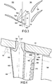
- wall 108a is straight, it is also conceivable to make it curved and convex, as in the embodiment illustrated in FIG. figure 4 , to optimize the aerodynamics of the passage 108 and thus reduce the pressure losses in this passage.
- the rest of the elements in this figure are equivalent to those of the first embodiment, and consequently receive the same references. It would also be possible to have such internal cavities and / or an outlet passage capable of injecting an air jet into the boundary layer only in a subset of the stator vanes.
Description
La présente invention concerne le domaine des turbomachines et plus particulièrement celui des compresseurs.The present invention relates to the field of turbomachines and more particularly that of compressors.
On entend par turbomachine, dans le présent contexte, toute machine dans laquelle peut s'opérer un transfert d'énergie entre un écoulement de fluide et au moins un aubage, comme, par exemple, un compresseur, une pompe, une turbine, ou bien une combinaison d'au moins deux de ceux-ci. Les termes « amont » et « aval » sont définis par rapport au sens de circulation normal du fluide de travail à travers la turbomachine.In the present context, the term "turbomachine" means any machine in which energy transfer can take place between a fluid flow and at least one blade, such as, for example, a compressor, a pump or a turbine, or else a combination of at least two of these. The terms "upstream" and "downstream" are defined with respect to the direction of normal circulation of the working fluid through the turbomachine.
Parmi les turbomachines on compte notamment les moteurs thermiques à turbine, qui permettent la conversion de l'énergie chimique d'un carburant en énergie thermique par combustion du carburant, et ensuite la conversion de cette énergie thermique en énergie mécanique par détente d'un fluide de travail chauffé par la combustion du carburant.Among the turbomachines there are notably turbine engines, which allow the conversion of the chemical energy of a fuel into thermal energy by combustion of the fuel, and then the conversion of this thermal energy into mechanical energy by expansion of a fluid. heated by burning fuel.
Dans les moteurs thermiques à turbine à combustion interne, tels que les turbines de gaz, les turbomoteurs, les turboréacteurs à simple ou double flux, ou les turbopropulseurs, la combustion s'opère directement dans le fluide de travail, qui est typiquement de l'air. Typiquement ces moteurs thermiques à turbine à combustion interne comportent au moins un compresseur en amont de la chambre de combustion et au moins une turbine, en aval de la chambre de combustion, couplée au compresseur pour son actionnement par une détente partielle du fluide de travail chauffé par la combustion du carburant. Normalement, un restant d'énergie thermique du fluide de travail peut alors être récupéré en tant qu'énergie mécanique par une tuyère de réaction et/ou au moins une turbine supplémentaire couplée à un arbre moteur.In combustion engines with an internal combustion turbine, such as gas turbines, turboshaft engines, single or double flow turbofan engines, or turboprops, combustion takes place directly in the working fluid, which is typically air. Typically, these internal combustion turbine heat engines comprise at least one compressor upstream of the combustion chamber and at least one turbine, downstream of the combustion chamber, coupled to the compressor for its actuation by partial expansion of the heated working fluid. by burning fuel. Normally, a remainder of thermal energy of the working fluid can then be recovered as mechanical energy by a reaction nozzle and / or at least one additional turbine coupled to a motor shaft.
Parmi les compresseurs, on compte notamment les compresseurs axiaux, dans lesquels la direction d'écoulement du fluide de travail est sensiblement parallèle à un axe central de rotation d'au moins un aubage rotatif, ou rotor, transférant de l'énergie au fluide de travail pour sa compression. Dans un étage de compresseur axial, le rotor comprend typiquement une pluralité de pales arrangées radialement, chaque pale du rotor s'étendant d'un pied de pale à une tête de pale plus éloignée que le pied de pale de l'axe central et présentant un jeu radial entre la tête de pale et un carter délimitant la veine de circulation du fluide de travail. Ce jeu radial est normalement nécessaire pour empêcher le contact des têtes de pale avec le carter, contact qui non seulement générerait des pertes par frottement, mais risquerait même d'endommager le carter et/ou le rotor. Toutefois, ce jeu permet aussi la naissance d'un tourbillon en bout de pale, tourbillon qui non seulement dégrade sensiblement le rendement de l'étage de compresseur, mais qui est également nuisible à la marge en stabilité du rotor, en particulier sur les premiers étages de compresseur.Compressors include axial compressors, in which the flow direction of the working fluid is substantially parallel to a central axis of rotation of at least one rotary blade, or rotor, transferring energy to the working fluid for its compression. In an axial compressor stage, the rotor typically comprises a plurality of radially arranged blades, each rotor blade extending from a blade root to a blade head further away than the blade root of the central axis and having a radial clearance between the blade head and a housing defining the flow passage of the working fluid. This radial clearance is normally necessary to prevent contact of the blade heads with the housing, which contact would not only generate friction losses, but could even damage the housing and / or the rotor. However, this game also allows the birth of a tourbillon at the end of the blade, a vortex which not only substantially degrades the efficiency of the compressor stage, but which is also detrimental to the stability margin of the rotor, in particular on the first compressor stages.
Afin de souffler ces tourbillons de jeu, il a déjà été proposé dans l'état de la technique, par exemple dans les brevets
En même temps, un tel étage de compresseur comprend normalement aussi un stator comprenant une pluralité d'aubes directrices arrangées radialement autour d'un axe central dans la veine d'air en amont du rotor. Ces aubes directrices, surtout dans un premier étage de compresseur de turbopropulseur, turbomoteur ou turboréacteur à simple flux, peuvent présenter un risque de givrage. Pour limiter ce risque de givrage, des dispositifs électriques ont été proposés, ainsi que des variations d'angle d'attaque des aubes directrices. Toutefois, ces dispositifs augmentent aussi la complexité et le poids de l'étage de compresseur, ou ont un impact négatif sur ses performances.At the same time, such a compressor stage normally also comprises a stator comprising a plurality of guide vanes arranged radially about a central axis in the air stream upstream of the rotor. These guide vanes, especially in a first stage turboprop compressor, turbine engine or turbojet engine, may present a risk of icing. To limit this risk of icing, electrical devices have been proposed, as well as variations of angle of attack of the guide vanes. However, these devices also increase the complexity and weight of the compressor stage, or have a negative impact on its performance.
La présente divulgation vise à remédier à ces inconvénients, en proposant un étage de compresseur avec dégivrage des aubes directrices et une marge de stabilité plus élevée, mais une complexité restreinte. Cet étage de compresseur peut comprendre au moins un carter délimitant une veine d'air, un stator comprenant une pluralité d'aubes directrices arrangées radialement autour d'un axe central dans la veine d'air, et un rotor, apte à tourner autour de l'axe central par rapport au stator, et comprenant une pluralité de pales arrangées radialement autour de l'axe central en aval des aubes directrices dans la veine d'air, chaque pale du rotor s'étendant d'un pied de pale à une tête de pale plus éloignée que le pied de pale de l'axe central et présentant un jeu radial entre la tête de pale et le carter. L'étage de compresseur peut notamment être un étage axial, quoique l'invention puisse aussi être éventuellement appliquée sur un étage du type dit radial ou centrifuge.The present disclosure aims to remedy these drawbacks by proposing a compressor stage with defrosting of the guide vanes and a higher margin of stability, but a limited complexity. This compressor stage may comprise at least one casing delimiting an air stream, a stator comprising a plurality of guide vanes arranged radially about a central axis in the air stream, and a rotor, able to rotate around the central axis relative to the stator, and comprising a plurality of blades arranged radially about the central axis downstream of the guide vanes in the air stream, each rotor blade extending from a blade root to a blade head farther than the blade root of the central axis and having a radial clearance between the blade head and the housing. The compressor stage may in particular be an axial stage, although the invention may also be optionally applied to a so-called radial or centrifugal stage.
Dans au moins un mode de réalisation le but recherché est atteint grâce au fait que au moins une desdites aubes directrices comprend une cavité interne avec une entrée d'air chaud pour dégivrer cette aube directrice, et en ce que la cavité interne présente un premier passage de sortie vers un bord de fuite de l'aube directrice pour l'injection d'un jet d'air dans une couche limite adjacente au carter en amont des pales du rotor.In at least one embodiment, the aim is achieved by virtue of the fact that at least one of said guide vanes comprises an internal cavity with a hot air inlet for deicing said guide vane, and in that the internal cavity has a first passage. output to a trailing edge of the guide vane for injection of an air jet into a boundary layer adjacent to the casing upstream of the rotor blades.
Grâce à ces dispositions, il est possible d'assurer d'une part le dégivrage de l'aube directrice, et d'autre part l'injection d'un jet d'air, refroidi dans la cavité interne de l'aube et donc plus dense que via une réinjection sans circuit de dégivrage, dans la couche limite de manière à souffler les tourbillons de jeu en aval et donc augmenter la marge de stabilité et le rendement du compresseur.Thanks to these provisions, it is possible to ensure on the one hand the defrosting of the guide vane, and on the other hand the injection of an air jet, cooled in the internal cavity of the blade and therefore denser than via reinjection without de-icing circuit, in the boundary layer so as to blow the gyres downstream and thus increase the margin of stability and the efficiency of the compressor.
Afin de diriger le jet d'air vers la couche limite, ledit premier passage de sortie peut être délimité du côté de l'axe central, dans un plan axial et radial, par une surface convergeant vers le carter en aval. Cette surface peut être notamment courbe et convexe dans le plan axial et radial, pour une plus grande efficacité aérodynamique, mais pourrait alternativement être droite.In order to direct the air jet towards the boundary layer, said first outlet passage may be delimited on the central axis side, in an axial and radial plane, by a surface converging towards the downstream housing. This surface may in particular be curved and convex in the axial and radial plane, for greater aerodynamic efficiency, but may alternatively be straight.
D'autre part, afin de suivre le contour du carter, ledit premier passage de sortie peut être délimité d'un côté opposé à l'axe central, dans un plan axial et radial, par une surface présentant, par rapport à une direction axiale, un angle d'inclinaison vers l'axe central en aval entre 0° et 30°.On the other hand, in order to follow the contour of the housing, said first outlet passage may be delimited on a side opposite to the central axis, in an axial and radial plane, by a surface having, with respect to an axial direction , an angle of inclination towards the central axis downstream between 0 ° and 30 °.
En particulier, ledit premier passage de sortie peut être convergent vers l'aval, formant ainsi une tuyère convergente pour accélérer le jet d'air. Dans un plan axial et radial, ledit passage de sortie peut notamment présenter un angle de convergence entre 10° et 60°.In particular, said first outlet passage may converge downstream, thus forming a convergent nozzle to accelerate the air jet. In an axial and radial plane, said output passage may in particular have a convergence angle between 10 ° and 60 °.
Pour une plus grande efficacité, ledit premier passage de sortie peut déboucher dans une fente sur une surface externe de l'aube directrice. Cette fente peut présenter un bord inférieur situé entre 80% et 95% d'une hauteur de veine et/ou un bord supérieur situé entre 90% et 100% de la hauteur de veine. Dans ce contexte, on entend par « hauteur de veine » la distance en direction radiale d'un bord intérieur de la veine d'air, du côté de l'axe central, à un bord extérieur de la veine d'air, du côté du carter, au niveau de la fente, et les positions du bord inférieur et du bord supérieur de la fente sont mesurées en direction radiale vers l'extérieur à partir du bord inférieur de la veine d'air.For greater efficiency, said first exit passage may open into a slot on an outer surface of the guide vane. This slot may have a lower edge between 80% and 95% of a vein height and / or an upper edge between 90% and 100% of the vein height. In this context, the term "vein height" means the radial distance from an inner edge of the air stream, on the central axis side, to an outer edge of the airstream, on the other side. of the housing, at the slot, and the positions of the lower edge and the upper edge of the slot are measured radially outwardly from the lower edge of the air stream.
Pour faciliter la provision d'air chaud, l'entrée d'air chaud peut notamment être située radialement vers l'extérieur par rapport à la cavité interne. Dans ce cas, pour assurer un meilleur échange thermique, la cavité interne peut présenter une cloison radiale, située entre l'entrée et le premier passage de sortie, et ouverte à une extrémité opposée à l'entrée d'air. L'air chaud suivra ainsi un parcours serpentin, cédant ainsi plus de chaleur à l'aube directrice pour mieux assurer son dégivrage et être injecté à une température moins élevée dans la couche limite.To facilitate the supply of hot air, the hot air inlet may in particular be located radially outwardly relative to the internal cavity. In this case, to ensure a better heat exchange, the internal cavity may have a radial partition, located between the inlet and the first outlet passage, and open at an end opposite to the air inlet. The hot air will follow a serpentine path, giving way to more heat at the director's dawn to better ensure its de-icing and be injected at a lower temperature in the boundary layer.
Pour permettre le passage d'un plus grand débit d'air chaud pour le dégivrage, la cavité interne peut présenter au moins un autre passage de sortie, débouchant séparément du premier passage de sortie sur le bord de fuite de l'aube directrice, à une position plus proche de l'axe central que le premier passage de sortie. Toutefois, le premier passage de sortie peut présenter une section transversale supérieure à l'autre passage de sortie.To allow the passage of a larger flow of hot air for deicing, the internal cavity may have at least one other outlet passage, opening separately from the first outlet passage on the trailing edge of the guide vane, to a position closer to the central axis than the first exit passage. However, the first output passage may have a larger cross section than the other output passage.
Pour augmenter le rendement de l'étage de compresseur axial à plusieurs régimes, les aubes directrices peuvent être à incidence variable.To increase the efficiency of the axial compressor stage at several speeds, the guide vanes may be of variable incidence.
La présente divulgation se rapporte aussi à un compresseur comprenant un tel étage de compresseur axial, en particulier comme premier étage, ainsi qu'à une turbomachine, notamment un moteur thermique à turbine à combustion interne et plus particulièrement un turbopropulseur, quoiqu'un turbomoteur, un turboréacteur ou une turbine à gaz soient aussi envisageables, entre autres, comprenant un tel étage de compresseur.The present disclosure also relates to a compressor comprising such an axial compressor stage, in particular as a first stage, and to a turbomachine, in particular an internal combustion turbine heat engine and more particularly a turboprop engine, even though a turbine engine, a turbojet or a gas turbine are also possible, among others, including such a compressor stage.
La présente divulgation se rapporte par ailleurs aussi à un procédé de suppression de tourbillon de jeu de tête de pale d'un tel étage de compresseur, dans lequel un jet d'air ayant circulé à travers la cavité interne de l'aube directrice pour son dégivrage est injecté en amont des pales du rotor, à travers le premier passage de sortie, dans une couche limite adjacente au carter en amont des pales du rotor et traversée par les têtes de pale, de manière à énergiser la couche limite.The present disclosure also relates to a vane head vortex vortex removal method of such a compressor stage, in which an air jet has flowed through the internal cavity of the vane director for its deicing is injected upstream of the rotor blades, through the first exit passage, into a boundary layer adjacent to the casing upstream of the rotor blades and traversed by the blade heads, so as to energize the boundary layer.
L'invention sera bien comprise et ses avantages apparaîtront mieux, à la lecture de la description détaillée qui suit, de modes de réalisation représentés à titre d'exemples non limitatifs. La description se réfère aux dessins annexés sur lesquels :
- la
figure 1 est une vue schématique en coupe longitudinale d'un turbopropulseur avec un compresseur multi-étages ; - la
figure 2 est une vue schématique d'un premier étage du compresseur du turbopropulseur de lafigure 1 suivant un premier mode de réalisation de l'invention ; - la
figure 3 est un schéma illustrant l'effet d'un jet d'air injecté dans la couche limite adjacente au carter en amont du rotor sur l'incidence effective en tête de pale du rotor ; et - la
figure 4 est une vue schématique d'un premier étage de compresseur suivant un deuxième mode de réalisation de l'invention.
- the
figure 1 is a schematic view in longitudinal section of a turboprop with a multi-stage compressor; - the
figure 2 is a schematic view of a first stage of the turboprop compressor of thefigure 1 according to a first embodiment of the invention; - the
figure 3 is a diagram illustrating the effect of a jet of air injected into the boundary layer adjacent to the casing upstream of the rotor on the effective incidence at the head of the rotor blade; and - the
figure 4 is a schematic view of a first compressor stage according to a second embodiment of the invention.
La
La
Chaque pale 105 du rotor 104 s'étend radialement d'un pied de pale 105a à une tête de pale 105b à proximité du carter 101. Un jeu j sépare la tête de pale 105b du carter 101, pour empêcher leur contact. Toutefois, des fuites de l'intrados à l'extrados de chaque pale 105 à travers ce jeu j réduisent la marge de stabilité et le rendement de ce premier étage 100 du compresseur 4. Par ailleurs, ces fuites causent des tourbillons qui peuvent se propager en aval du premier compresseur 4, générant des pertes de rendement et des vibrations supplémentaires aux autres étages.Each
Chaque aube 103 du stator 102 est connectée au carter 101 par un pivot 120 lui permettant de pivoter autour d'un axe radial Y afin de faire varier l'incidence de l'aube 103 par rapport à l'écoulement dans la veine d'air. En outre, dans le mode de réalisation illustré, chaque aube 103 est creuse, présentant une cavité interne 106 connectée à une source d'air chaud à travers une entrée 107 dans le pivot 120. La cavité interne 106 présente aussi une pluralité de passages de sortie 108,109 vers des fentes 110,111 au bord de fuite 112 de l'aube 103, afin de permettre un écoulement de l'air chaud, à travers la cavité interne 106, de l'entrée 107 vers les fentes 110, 111 de sortie. Par ailleurs, la cavité interne 106 présente aussi une nervure 113, formant une cloison radiale partielle dans la cavité 106, entre l'entrée 107 et les passages de sortie 108, 109, ouverte à l'extrémité opposée à l'entrée 107 en direction radiale. Ainsi, l'écoulement d'air chaud à travers la cavité interne 106 va suivre un parcours serpentin, avec un premier segment dans lequel l'air circule en direction sensiblement radiale de l'extérieur vers l'intérieur, un deuxième segment dans lequel l'air circule en direction sensiblement radiale de l'intérieur vers l'extérieur, et un coude entre les deux segments, au niveau de l'ouverture à travers la nervure 113. Ainsi, la nervure 113 allonge le parcours de l'air chaud à travers la cavité 106, maximisant ainsi l'échange de chaleur entre cet air chaud et l'aube 103.
En outre, parmi les passages de sortie 108, 109, le passage 108 le plus proche au carter 101 présente une section d'écoulement plus importante que les autres, et une géométrie particulière. Plus particulièrement, ce passage 108 est convergent en aval, formant ainsi une tuyère convergente accélérant l'écoulement de l'air en sortie pour former un jet d'air 114. Du côté radialement intérieur, c'est-à-dire du côté de l'axe central X, le passage 108 est délimité par une paroi 108a qui, dans le plan radial et axial illustré, converge vers le carter 101 en aval. Du côté radialement extérieur, c'est-à-dire du côté opposé à l'axe central X, le passage 108 est délimité par une paroi 108b qui, dans le même plan radial et axial, peut être approximativement parallèle au carter 101. Ainsi, comme le carter 101 peut être légèrement convergent en aval, la paroi 108b peut présenter, dans ce plan radial et axial, un angle α (ALPHA) de, par exemple, entre 0° et 30° par rapport à l'axe central X, convergeant ainsi vers l'axe central X en aval. L'angle β (BETA) de convergence entre les parois 108a et 108b vers l'aval peut être, par exemple, entre 10° et 60°. Le passage 108 débouche dans une fente 108c sur une surface externe de l'aube 103. Cette fente 108c peut être située directement sur le bord de fuite 112 de l'aube 103, quoique d'autres positions à proximité du bord de fuite 112, comme par exemple sur l'extrados ou l'intrados de l'aube 103, entre son maitre-couple et le bord de fuite 112, soient également envisageables. Dans le mode de réalisation illustré, avec une hauteur de veine h d'un bord intérieur 2i au bord extérieur 2e de la veine d'air 2 à la position axiale de la fente 108c, un bord inférieur 108i de la fente 108c est situé à une distance radiale di du bord intérieur 2i de la veine d'air 2 de, par exemple, entre 80% et 95% de la hauteur de veine h et un bord supérieur 108s de la fente 108c est situé à une distance radiale ds du bord intérieur 2i de la veine d'air 2 de, par exemple, entre 90% et 100% de la hauteur de veine h.Each
In addition, among the
En fonctionnement, l'air chaud introduit dans la cavité 106 à travers l'entrée 107 va traverser cette cavité 106 jusqu'aux passages de sortie 108, 109. En ce faisant, l'air chaud, qui peut provenir d'une prise en aval d'au moins cet étage de compresseur 100, va chauffer l'aube 103, assurant ainsi son dégivrage, tout en se refroidissant. Le passage de sortie 108 va ainsi injecter un jet d'air 114 relativement froid, et donc dense, dans une couche limite 115 adjacente au carter 101 et traversée par les têtes 104b des pales 104 dans leur rotation, de manière à énergiser cette couche limite 115 en amont des pales. La
Bien que dans le mode de réalisation illustré sur la
Quoique la présente invention ait été décrite en se référant à des exemples de réalisation spécifiques, il est évident que des différentes modifications et changements peuvent être effectués sur ces exemples sans sortir de la portée générale de l'invention telle que définie par les revendications. En outre, des caractéristiques individuelles des différents modes de réalisation évoqués peuvent être combinées dans des modes de réalisation additionnels. Par conséquent, la description et les dessins doivent être considérés dans un sens illustratif plutôt que restrictif.Although the present invention has been described with reference to specific exemplary embodiments, it is obvious that various modifications and changes can be made to these examples without departing from the general scope of the invention as defined by the claims. In addition, individual features of the various embodiments mentioned can be combined in additional embodiments. Therefore, the description and drawings should be considered in an illustrative rather than restrictive sense.
Claims (14)
- A compressor stage (100) comprising at least:a casing (101) delimiting an air passage (2);a stator (102) comprising a plurality of guide vanes (103) arranged radially around a central axis (X) in the air passage (2); anda rotor (104) rotatable about the central axis (X) relative to the stator (102) and comprising a plurality of blades (105) arranged radially around the central axis (X) in the air passage (2) downstream from the guide vanes (103), each blade (105) of the rotor (104) extending from a blade root (105a) to a blade tip (105b) further away from the central axis (X) than the blade root (105a) and presenting radial clearance (j) between the blade tip (105b) and the casing (101);the compressor stage (100) being characterized in that at least one of said guide vanes (103) includes an internal cavity (106) with a hot air inlet (107) for deicing the guide vane (103), and in that the internal cavity (106) presents a first outlet passage (108) towards a trailing edge (112) of the guide vane (103) for injecting an air jet (114) into a boundary layer (115) adjacent to the casing (101) upstream from the blades (105) of the rotor (104).
- A compressor stage (100) according to claim 1, wherein, in an axial and radial plane, said first outlet passage (108) is delimited towards the central axis by a surface (108a) that converges downstream towards the casing (101).
- A compressor stage (100) according to claim 2, wherein the surface (108a) delimiting the first outlet passage (108) beside the central axis (X) is curved and convex in the axial and radial plane.
- A compressor stage (100) according to any one of the previous claims, wherein, in an axial and radial plane, said first outlet passage (108) is delimited away from the central axis (X) by a surface (108b) that presents, relative to an axial direction, an angle of inclination (a) in the range 0° to 30° towards the central axis downstream.
- A compressor stage (100) according to any one to the previous claims, wherein said first outlet passage (108) converges downstream.
- A compressor stage (100) according to claim 5, wherein, in an axial and radial plane, said first outlet passage (108) presents an angle of convergence (β) in the range 10° to 60°.
- A compressor stage (100) according to any one to the previous claims, wherein said first outlet passage (108) opens out in a slot (108c) in an outside surface of the guide vane (103).
- A compressor stage (100) according to any one to the previous claims, wherein the hot air inlet (107) is situated radially on the outside relative to the internal cavity (106), and the internal cavity (106) presents a radial partition (113) situated between the inlet (107) and the first outlet passage (108) and open at an end remote from the air inlet (107).
- A compressor stage (100) according to any one to the previous claims, wherein the internal cavity presents at least one other outlet passage (109) opening out separately from the first outlet passage (108) in the trailing edge (112) of the guide vane (103) in a position that is closer to the central axis (X) than is the first outlet passage (108).
- A compressor stage (100) according to claim 9, wherein the first outlet passage (108) presents a cross-section that is greater than the other outlet passage (109).
- A compressor stage (100) according to any one to the previous claims, wherein the guide vanes (103) are of variable angle of incidence.
- A compressor (4) including a first stage (100) according to claim 1.
- A turboprop (1) including a compressor (4) according to claim 12.
- A method of eliminating blade tip clearance vortices in a compressor stage according to any one of claims 1 to 11, wherein a jet (114) of air that has flowed through the internal cavity (106) of the guide vane (103) in order to deice it is injected upstream from the blades (105) of the rotor (104) and through the first outlet passage (108) into a boundary layer (115) adjacent to the casing (101) upstream from the blades (105) of the rotor (104) and through which the blade tips (105b) pass, for the purpose of energizing the boundary layer (115).
Applications Claiming Priority (2)
| Application Number | Priority Date | Filing Date | Title |
|---|---|---|---|
| FR1552537A FR3034145B1 (en) | 2015-03-26 | 2015-03-26 | COMPRESSOR FLOOR |
| PCT/FR2016/050692 WO2016151268A1 (en) | 2015-03-26 | 2016-03-25 | Compressor stage |
Publications (2)
| Publication Number | Publication Date |
|---|---|
| EP3274564A1 EP3274564A1 (en) | 2018-01-31 |
| EP3274564B1 true EP3274564B1 (en) | 2018-11-28 |
Family
ID=53040647
Family Applications (1)
| Application Number | Title | Priority Date | Filing Date |
|---|---|---|---|
| EP16729295.2A Active EP3274564B1 (en) | 2015-03-26 | 2016-03-25 | Comressor stage |
Country Status (5)
| Country | Link |
|---|---|
| US (1) | US20180066536A1 (en) |
| EP (1) | EP3274564B1 (en) |
| CN (1) | CN107532515A (en) |
| FR (1) | FR3034145B1 (en) |
| WO (1) | WO2016151268A1 (en) |
Families Citing this family (12)
| Publication number | Priority date | Publication date | Assignee | Title |
|---|---|---|---|---|
| RU177516U1 (en) * | 2017-07-21 | 2018-02-28 | Научно-производственная ассоциация "Технопарк Авиационных Технологий" | Paddle for adjustable inlet guide vane |
| CN108104886A (en) * | 2017-11-28 | 2018-06-01 | 中国航发沈阳发动机研究所 | A kind of anti-icing rectification support plate and with its engine pack |
| GB201820400D0 (en) * | 2018-12-14 | 2019-01-30 | Rolls Royce Plc | Ice crystal protection for a gas turbine engine |
| US10876549B2 (en) | 2019-04-05 | 2020-12-29 | Pratt & Whitney Canada Corp. | Tandem stators with flow recirculation conduit |
| CA3073417A1 (en) * | 2019-04-18 | 2020-10-18 | Pratt & Whitney Canada Corp. | Fan blade ice protection using hot air |
| IT201900007935A1 (en) * | 2019-06-04 | 2020-12-04 | R E M Holding S R L | FAN WITH IMPROVED FAN |
| US11118457B2 (en) * | 2019-10-21 | 2021-09-14 | Pratt & Whitney Canada Corp. | Method for fan blade heating using coanda effect |
| EP3855059B1 (en) * | 2020-01-24 | 2023-11-15 | Aptiv Technologies Limited | Passive flow divider and liquid cooling system comprising the same |
| WO2022228734A2 (en) * | 2021-04-26 | 2022-11-03 | Malte Schwarze | Efficiently generating thrust |
| CN113530888B (en) * | 2021-08-24 | 2022-08-09 | 中国航发湖南动力机械研究所 | Multi-cavity integrated guide vane casing structure with anti-icing function |
| GB202117857D0 (en) * | 2021-12-10 | 2022-01-26 | Rolls Royce Plc | Vane assembly for a gas turbine engine |
| FR3138468A1 (en) | 2022-07-29 | 2024-02-02 | Safran Aircraft Engines | METAL LEADING EDGE SHIELD FOR TURBOMACHINE BLADE, TURBOMACHINE BLADE, METHOD OF MANUFACTURING AND USE |
Family Cites Families (14)
| Publication number | Priority date | Publication date | Assignee | Title |
|---|---|---|---|---|
| GB879981A (en) * | 1956-09-13 | 1961-10-11 | Wiggin & Co Ltd Henry | Improvements in and relating to hollow turbine blades |
| US3123283A (en) * | 1962-12-07 | 1964-03-03 | Anti-icing valve means | |
| GB1012909A (en) * | 1962-12-07 | 1965-12-08 | Gen Electric | Improvements in anti-icing means for the compressor of a gas turbine engine |
| US3572960A (en) * | 1969-01-02 | 1971-03-30 | Gen Electric | Reduction of sound in gas turbine engines |
| US5762034A (en) * | 1996-01-16 | 1998-06-09 | Board Of Trustees Operating Michigan State University | Cooling fan shroud |
| US6055805A (en) * | 1997-08-29 | 2000-05-02 | United Technologies Corporation | Active rotor stage vibration control |
| DE102004030597A1 (en) * | 2004-06-24 | 2006-01-26 | Rolls-Royce Deutschland Ltd & Co Kg | Turbomachine with external wheel jet generation at the stator |
| FR2916815B1 (en) * | 2007-05-30 | 2017-02-24 | Snecma | AIR REINJECTION COMPRESSOR |
| CN100470061C (en) * | 2007-08-09 | 2009-03-18 | 上海交通大学 | Impeller mechanical wing profile with suction edge injection |
| FR2931906B1 (en) | 2008-05-30 | 2017-06-02 | Snecma | TURBOMACHINE COMPRESSOR WITH AIR INJECTION SYSTEM. |
| FR2949518B1 (en) | 2009-08-31 | 2011-10-21 | Snecma | TURBOMACHINE COMPRESSOR HAVING AIR INJECTORS |
| GB201009264D0 (en) * | 2010-06-03 | 2010-07-21 | Rolls Royce Plc | Heat transfer arrangement for fluid washed surfaces |
| US9045987B2 (en) * | 2012-06-15 | 2015-06-02 | United Technologies Corporation | Cooling for a turbine airfoil trailing edge |
| US9206695B2 (en) * | 2012-09-28 | 2015-12-08 | Solar Turbines Incorporated | Cooled turbine blade with trailing edge flow metering |
-
2015
- 2015-03-26 FR FR1552537A patent/FR3034145B1/en active Active
-
2016
- 2016-03-25 WO PCT/FR2016/050692 patent/WO2016151268A1/en active Application Filing
- 2016-03-25 CN CN201680022291.1A patent/CN107532515A/en active Pending
- 2016-03-25 EP EP16729295.2A patent/EP3274564B1/en active Active
- 2016-03-25 US US15/561,192 patent/US20180066536A1/en not_active Abandoned
Non-Patent Citations (1)
| Title |
|---|
| None * |
Also Published As
| Publication number | Publication date |
|---|---|
| WO2016151268A1 (en) | 2016-09-29 |
| FR3034145B1 (en) | 2017-04-07 |
| CN107532515A (en) | 2018-01-02 |
| US20180066536A1 (en) | 2018-03-08 |
| EP3274564A1 (en) | 2018-01-31 |
| FR3034145A1 (en) | 2016-09-30 |
Similar Documents
| Publication | Publication Date | Title |
|---|---|---|
| EP3274564B1 (en) | Comressor stage | |
| EP0856641B1 (en) | Cooling system for the shroud of rotor blades | |
| EP2834470B1 (en) | Turbomachine rotor blade, corresponding blisk, compressor rotor and fan rotor | |
| CA2837498C (en) | Variable-pitch nozzle for a radial flow turbine, in particular for a turbine of an auxiliary power source | |
| EP3312391B1 (en) | Deicing inlet of an axial turbine engine compressor | |
| JP2015537150A (en) | Curved stator shroud | |
| FR2875841A1 (en) | METHOD AND DEVICE FOR ROTOR BLADES WITH AERODYNAMIC SELF-AMELIORATION | |
| CA2836040C (en) | Centrifugal compressor impeller | |
| FR3021699A1 (en) | OPTIMIZED COOLING TURBINE BLADE AT ITS LEFT EDGE | |
| FR3051219B1 (en) | TURBOMACHINE TURBINE, SUCH AS A TURBOREACTOR OR AIRCRAFT TURBOPROPOWER | |
| US10408068B2 (en) | Fan blade dovetail and spacer | |
| EP3485146B1 (en) | Turbofan engine and corresponding method of operating | |
| FR3036140B1 (en) | AIRCRAFT TURBOMACHINE WITH COANDA EFFECT | |
| FR3021698A1 (en) | TURBINE DAWN, COMPRISING A THERMALLY ISOLATED CENTRAL COOLING DUCT OF WINDOW BLINDS BY TWO JOINT SIDE CAVITIES DOWNSTREAM OF THE CENTRAL CONDUIT | |
| EP4127409A1 (en) | Turbomachine rotary-fan blade, fan and turbomachine provided therewith | |
| EP3829975B1 (en) | Turbomachine with coaxial propellers | |
| FR3103215A1 (en) | Turbomachine rotary fan blade, fan and turbomachine fitted therewith | |
| FR3092135A1 (en) | TURBOMACHINE, SUCH AS AN AIRPLANE TURBOREACTOR | |
| FR3073002A1 (en) | GUIDE VANE WITH COOLANT INJECTION CIRCUIT | |
| FR3121470A1 (en) | Device for sealing and reinjecting a bypass flow for a turbine nozzle | |
| WO2022069845A1 (en) | Turbine blade for an aircraft turbine engine, comprising a platform provided with a channel for primary flow rejection towards a purge cavity | |
| FR3108663A1 (en) | Turbomachine rotary fan blade, fan and turbomachine fitted therewith | |
| FR3131939A1 (en) | AXIAL TURBOMACHINE SPLITTER INCLUDING DEFROST AIR FLOW PASSAGE EXTENDING TO RECTIFIER | |
| EP3867499A1 (en) | Turbine engine blade with improved cooling | |
| FR3025835A1 (en) | TURBOMACHINE TURBINE AUB COOLING AIR CIRCULATION SYSTEM |
Legal Events
| Date | Code | Title | Description |
|---|---|---|---|
| STAA | Information on the status of an ep patent application or granted ep patent |
Free format text: STATUS: THE INTERNATIONAL PUBLICATION HAS BEEN MADE |
|
| PUAI | Public reference made under article 153(3) epc to a published international application that has entered the european phase |
Free format text: ORIGINAL CODE: 0009012 |
|
| STAA | Information on the status of an ep patent application or granted ep patent |
Free format text: STATUS: REQUEST FOR EXAMINATION WAS MADE |
|
| 17P | Request for examination filed |
Effective date: 20171024 |
|
| AK | Designated contracting states |
Kind code of ref document: A1 Designated state(s): AL AT BE BG CH CY CZ DE DK EE ES FI FR GB GR HR HU IE IS IT LI LT LU LV MC MK MT NL NO PL PT RO RS SE SI SK SM TR |
|
| AX | Request for extension of the european patent |
Extension state: BA ME |
|
| DAV | Request for validation of the european patent (deleted) | ||
| DAX | Request for extension of the european patent (deleted) | ||
| GRAP | Despatch of communication of intention to grant a patent |
Free format text: ORIGINAL CODE: EPIDOSNIGR1 |
|
| STAA | Information on the status of an ep patent application or granted ep patent |
Free format text: STATUS: GRANT OF PATENT IS INTENDED |
|
| INTG | Intention to grant announced |
Effective date: 20180822 |
|
| GRAS | Grant fee paid |
Free format text: ORIGINAL CODE: EPIDOSNIGR3 |
|
| GRAA | (expected) grant |
Free format text: ORIGINAL CODE: 0009210 |
|
| STAA | Information on the status of an ep patent application or granted ep patent |
Free format text: STATUS: THE PATENT HAS BEEN GRANTED |
|
| AK | Designated contracting states |
Kind code of ref document: B1 Designated state(s): AL AT BE BG CH CY CZ DE DK EE ES FI FR GB GR HR HU IE IS IT LI LT LU LV MC MK MT NL NO PL PT RO RS SE SI SK SM TR |
|
| REG | Reference to a national code |
Ref country code: CH Ref legal event code: EP |
|
| REG | Reference to a national code |
Ref country code: AT Ref legal event code: REF Ref document number: 1070493 Country of ref document: AT Kind code of ref document: T Effective date: 20181215 |
|
| REG | Reference to a national code |
Ref country code: DE Ref legal event code: R096 Ref document number: 602016007646 Country of ref document: DE |
|
| REG | Reference to a national code |
Ref country code: IE Ref legal event code: FG4D Free format text: LANGUAGE OF EP DOCUMENT: FRENCH |
|
| REG | Reference to a national code |
Ref country code: SE Ref legal event code: TRGR |
|
| REG | Reference to a national code |
Ref country code: NL Ref legal event code: MP Effective date: 20181128 |
|
| REG | Reference to a national code |
Ref country code: LT Ref legal event code: MG4D |
|
| REG | Reference to a national code |
Ref country code: AT Ref legal event code: MK05 Ref document number: 1070493 Country of ref document: AT Kind code of ref document: T Effective date: 20181128 |
|
| PG25 | Lapsed in a contracting state [announced via postgrant information from national office to epo] |
Ref country code: ES Free format text: LAPSE BECAUSE OF FAILURE TO SUBMIT A TRANSLATION OF THE DESCRIPTION OR TO PAY THE FEE WITHIN THE PRESCRIBED TIME-LIMIT Effective date: 20181128 Ref country code: IS Free format text: LAPSE BECAUSE OF FAILURE TO SUBMIT A TRANSLATION OF THE DESCRIPTION OR TO PAY THE FEE WITHIN THE PRESCRIBED TIME-LIMIT Effective date: 20190328 Ref country code: LT Free format text: LAPSE BECAUSE OF FAILURE TO SUBMIT A TRANSLATION OF THE DESCRIPTION OR TO PAY THE FEE WITHIN THE PRESCRIBED TIME-LIMIT Effective date: 20181128 Ref country code: BG Free format text: LAPSE BECAUSE OF FAILURE TO SUBMIT A TRANSLATION OF THE DESCRIPTION OR TO PAY THE FEE WITHIN THE PRESCRIBED TIME-LIMIT Effective date: 20190228 Ref country code: NO Free format text: LAPSE BECAUSE OF FAILURE TO SUBMIT A TRANSLATION OF THE DESCRIPTION OR TO PAY THE FEE WITHIN THE PRESCRIBED TIME-LIMIT Effective date: 20190228 Ref country code: HR Free format text: LAPSE BECAUSE OF FAILURE TO SUBMIT A TRANSLATION OF THE DESCRIPTION OR TO PAY THE FEE WITHIN THE PRESCRIBED TIME-LIMIT Effective date: 20181128 Ref country code: AT Free format text: LAPSE BECAUSE OF FAILURE TO SUBMIT A TRANSLATION OF THE DESCRIPTION OR TO PAY THE FEE WITHIN THE PRESCRIBED TIME-LIMIT Effective date: 20181128 Ref country code: LV Free format text: LAPSE BECAUSE OF FAILURE TO SUBMIT A TRANSLATION OF THE DESCRIPTION OR TO PAY THE FEE WITHIN THE PRESCRIBED TIME-LIMIT Effective date: 20181128 Ref country code: FI Free format text: LAPSE BECAUSE OF FAILURE TO SUBMIT A TRANSLATION OF THE DESCRIPTION OR TO PAY THE FEE WITHIN THE PRESCRIBED TIME-LIMIT Effective date: 20181128 |
|
| PG25 | Lapsed in a contracting state [announced via postgrant information from national office to epo] |
Ref country code: AL Free format text: LAPSE BECAUSE OF FAILURE TO SUBMIT A TRANSLATION OF THE DESCRIPTION OR TO PAY THE FEE WITHIN THE PRESCRIBED TIME-LIMIT Effective date: 20181128 Ref country code: RS Free format text: LAPSE BECAUSE OF FAILURE TO SUBMIT A TRANSLATION OF THE DESCRIPTION OR TO PAY THE FEE WITHIN THE PRESCRIBED TIME-LIMIT Effective date: 20181128 Ref country code: GR Free format text: LAPSE BECAUSE OF FAILURE TO SUBMIT A TRANSLATION OF THE DESCRIPTION OR TO PAY THE FEE WITHIN THE PRESCRIBED TIME-LIMIT Effective date: 20190301 Ref country code: PT Free format text: LAPSE BECAUSE OF FAILURE TO SUBMIT A TRANSLATION OF THE DESCRIPTION OR TO PAY THE FEE WITHIN THE PRESCRIBED TIME-LIMIT Effective date: 20190328 |
|
| PG25 | Lapsed in a contracting state [announced via postgrant information from national office to epo] |
Ref country code: NL Free format text: LAPSE BECAUSE OF FAILURE TO SUBMIT A TRANSLATION OF THE DESCRIPTION OR TO PAY THE FEE WITHIN THE PRESCRIBED TIME-LIMIT Effective date: 20181128 |
|
| PG25 | Lapsed in a contracting state [announced via postgrant information from national office to epo] |
Ref country code: DK Free format text: LAPSE BECAUSE OF FAILURE TO SUBMIT A TRANSLATION OF THE DESCRIPTION OR TO PAY THE FEE WITHIN THE PRESCRIBED TIME-LIMIT Effective date: 20181128 Ref country code: PL Free format text: LAPSE BECAUSE OF FAILURE TO SUBMIT A TRANSLATION OF THE DESCRIPTION OR TO PAY THE FEE WITHIN THE PRESCRIBED TIME-LIMIT Effective date: 20181128 Ref country code: CZ Free format text: LAPSE BECAUSE OF FAILURE TO SUBMIT A TRANSLATION OF THE DESCRIPTION OR TO PAY THE FEE WITHIN THE PRESCRIBED TIME-LIMIT Effective date: 20181128 |
|
| REG | Reference to a national code |
Ref country code: DE Ref legal event code: R097 Ref document number: 602016007646 Country of ref document: DE |
|
| PG25 | Lapsed in a contracting state [announced via postgrant information from national office to epo] |
Ref country code: RO Free format text: LAPSE BECAUSE OF FAILURE TO SUBMIT A TRANSLATION OF THE DESCRIPTION OR TO PAY THE FEE WITHIN THE PRESCRIBED TIME-LIMIT Effective date: 20181128 Ref country code: SM Free format text: LAPSE BECAUSE OF FAILURE TO SUBMIT A TRANSLATION OF THE DESCRIPTION OR TO PAY THE FEE WITHIN THE PRESCRIBED TIME-LIMIT Effective date: 20181128 Ref country code: EE Free format text: LAPSE BECAUSE OF FAILURE TO SUBMIT A TRANSLATION OF THE DESCRIPTION OR TO PAY THE FEE WITHIN THE PRESCRIBED TIME-LIMIT Effective date: 20181128 Ref country code: SK Free format text: LAPSE BECAUSE OF FAILURE TO SUBMIT A TRANSLATION OF THE DESCRIPTION OR TO PAY THE FEE WITHIN THE PRESCRIBED TIME-LIMIT Effective date: 20181128 |
|
| PLBE | No opposition filed within time limit |
Free format text: ORIGINAL CODE: 0009261 |
|
| STAA | Information on the status of an ep patent application or granted ep patent |
Free format text: STATUS: NO OPPOSITION FILED WITHIN TIME LIMIT |
|
| PG25 | Lapsed in a contracting state [announced via postgrant information from national office to epo] |
Ref country code: MC Free format text: LAPSE BECAUSE OF FAILURE TO SUBMIT A TRANSLATION OF THE DESCRIPTION OR TO PAY THE FEE WITHIN THE PRESCRIBED TIME-LIMIT Effective date: 20181128 |
|
| REG | Reference to a national code |
Ref country code: CH Ref legal event code: PL |
|
| 26N | No opposition filed |
Effective date: 20190829 |
|
| PG25 | Lapsed in a contracting state [announced via postgrant information from national office to epo] |
Ref country code: LU Free format text: LAPSE BECAUSE OF NON-PAYMENT OF DUE FEES Effective date: 20190325 |
|
| REG | Reference to a national code |
Ref country code: BE Ref legal event code: MM Effective date: 20190331 |
|
| PG25 | Lapsed in a contracting state [announced via postgrant information from national office to epo] |
Ref country code: IE Free format text: LAPSE BECAUSE OF NON-PAYMENT OF DUE FEES Effective date: 20190325 Ref country code: LI Free format text: LAPSE BECAUSE OF NON-PAYMENT OF DUE FEES Effective date: 20190331 Ref country code: CH Free format text: LAPSE BECAUSE OF NON-PAYMENT OF DUE FEES Effective date: 20190331 |
|
| PG25 | Lapsed in a contracting state [announced via postgrant information from national office to epo] |
Ref country code: BE Free format text: LAPSE BECAUSE OF NON-PAYMENT OF DUE FEES Effective date: 20190331 |
|
| PG25 | Lapsed in a contracting state [announced via postgrant information from national office to epo] |
Ref country code: TR Free format text: LAPSE BECAUSE OF FAILURE TO SUBMIT A TRANSLATION OF THE DESCRIPTION OR TO PAY THE FEE WITHIN THE PRESCRIBED TIME-LIMIT Effective date: 20181128 |
|
| PG25 | Lapsed in a contracting state [announced via postgrant information from national office to epo] |
Ref country code: MT Free format text: LAPSE BECAUSE OF FAILURE TO SUBMIT A TRANSLATION OF THE DESCRIPTION OR TO PAY THE FEE WITHIN THE PRESCRIBED TIME-LIMIT Effective date: 20181128 |
|
| PG25 | Lapsed in a contracting state [announced via postgrant information from national office to epo] |
Ref country code: CY Free format text: LAPSE BECAUSE OF FAILURE TO SUBMIT A TRANSLATION OF THE DESCRIPTION OR TO PAY THE FEE WITHIN THE PRESCRIBED TIME-LIMIT Effective date: 20181128 |
|
| PG25 | Lapsed in a contracting state [announced via postgrant information from national office to epo] |
Ref country code: HU Free format text: LAPSE BECAUSE OF FAILURE TO SUBMIT A TRANSLATION OF THE DESCRIPTION OR TO PAY THE FEE WITHIN THE PRESCRIBED TIME-LIMIT; INVALID AB INITIO Effective date: 20160325 |
|
| PG25 | Lapsed in a contracting state [announced via postgrant information from national office to epo] |
Ref country code: SI Free format text: LAPSE BECAUSE OF FAILURE TO SUBMIT A TRANSLATION OF THE DESCRIPTION OR TO PAY THE FEE WITHIN THE PRESCRIBED TIME-LIMIT Effective date: 20181128 |
|
| PG25 | Lapsed in a contracting state [announced via postgrant information from national office to epo] |
Ref country code: MK Free format text: LAPSE BECAUSE OF FAILURE TO SUBMIT A TRANSLATION OF THE DESCRIPTION OR TO PAY THE FEE WITHIN THE PRESCRIBED TIME-LIMIT Effective date: 20181128 |
|
| PGFP | Annual fee paid to national office [announced via postgrant information from national office to epo] |
Ref country code: FR Payment date: 20230222 Year of fee payment: 8 |
|
| PGFP | Annual fee paid to national office [announced via postgrant information from national office to epo] |
Ref country code: SE Payment date: 20230222 Year of fee payment: 8 Ref country code: IT Payment date: 20230221 Year of fee payment: 8 Ref country code: GB Payment date: 20230222 Year of fee payment: 8 Ref country code: DE Payment date: 20230221 Year of fee payment: 8 |