EP3274482B1 - A rock drill button - Google Patents
A rock drill button Download PDFInfo
- Publication number
- EP3274482B1 EP3274482B1 EP16713359.4A EP16713359A EP3274482B1 EP 3274482 B1 EP3274482 B1 EP 3274482B1 EP 16713359 A EP16713359 A EP 16713359A EP 3274482 B1 EP3274482 B1 EP 3274482B1
- Authority
- EP
- European Patent Office
- Prior art keywords
- rock drill
- cemented carbide
- equal
- drill button
- button according
- Prior art date
- Legal status (The legal status is an assumption and is not a legal conclusion. Google has not performed a legal analysis and makes no representation as to the accuracy of the status listed.)
- Active
Links
Images


Classifications
-
- C—CHEMISTRY; METALLURGY
- C22—METALLURGY; FERROUS OR NON-FERROUS ALLOYS; TREATMENT OF ALLOYS OR NON-FERROUS METALS
- C22C—ALLOYS
- C22C29/00—Alloys based on carbides, oxides, nitrides, borides, or silicides, e.g. cermets, or other metal compounds, e.g. oxynitrides, sulfides
- C22C29/02—Alloys based on carbides, oxides, nitrides, borides, or silicides, e.g. cermets, or other metal compounds, e.g. oxynitrides, sulfides based on carbides or carbonitrides
- C22C29/06—Alloys based on carbides, oxides, nitrides, borides, or silicides, e.g. cermets, or other metal compounds, e.g. oxynitrides, sulfides based on carbides or carbonitrides based on carbides, but not containing other metal compounds
- C22C29/067—Alloys based on carbides, oxides, nitrides, borides, or silicides, e.g. cermets, or other metal compounds, e.g. oxynitrides, sulfides based on carbides or carbonitrides based on carbides, but not containing other metal compounds comprising a particular metallic binder
-
- C—CHEMISTRY; METALLURGY
- C22—METALLURGY; FERROUS OR NON-FERROUS ALLOYS; TREATMENT OF ALLOYS OR NON-FERROUS METALS
- C22C—ALLOYS
- C22C29/00—Alloys based on carbides, oxides, nitrides, borides, or silicides, e.g. cermets, or other metal compounds, e.g. oxynitrides, sulfides
- C22C29/02—Alloys based on carbides, oxides, nitrides, borides, or silicides, e.g. cermets, or other metal compounds, e.g. oxynitrides, sulfides based on carbides or carbonitrides
- C22C29/06—Alloys based on carbides, oxides, nitrides, borides, or silicides, e.g. cermets, or other metal compounds, e.g. oxynitrides, sulfides based on carbides or carbonitrides based on carbides, but not containing other metal compounds
-
- C—CHEMISTRY; METALLURGY
- C22—METALLURGY; FERROUS OR NON-FERROUS ALLOYS; TREATMENT OF ALLOYS OR NON-FERROUS METALS
- C22C—ALLOYS
- C22C29/00—Alloys based on carbides, oxides, nitrides, borides, or silicides, e.g. cermets, or other metal compounds, e.g. oxynitrides, sulfides
- C22C29/02—Alloys based on carbides, oxides, nitrides, borides, or silicides, e.g. cermets, or other metal compounds, e.g. oxynitrides, sulfides based on carbides or carbonitrides
- C22C29/06—Alloys based on carbides, oxides, nitrides, borides, or silicides, e.g. cermets, or other metal compounds, e.g. oxynitrides, sulfides based on carbides or carbonitrides based on carbides, but not containing other metal compounds
- C22C29/08—Alloys based on carbides, oxides, nitrides, borides, or silicides, e.g. cermets, or other metal compounds, e.g. oxynitrides, sulfides based on carbides or carbonitrides based on carbides, but not containing other metal compounds based on tungsten carbide
-
- E—FIXED CONSTRUCTIONS
- E21—EARTH OR ROCK DRILLING; MINING
- E21B—EARTH OR ROCK DRILLING; OBTAINING OIL, GAS, WATER, SOLUBLE OR MELTABLE MATERIALS OR A SLURRY OF MINERALS FROM WELLS
- E21B10/00—Drill bits
- E21B10/46—Drill bits characterised by wear resisting parts, e.g. diamond inserts
- E21B10/50—Drill bits characterised by wear resisting parts, e.g. diamond inserts the bit being of roller type
-
- E—FIXED CONSTRUCTIONS
- E21—EARTH OR ROCK DRILLING; MINING
- E21B—EARTH OR ROCK DRILLING; OBTAINING OIL, GAS, WATER, SOLUBLE OR MELTABLE MATERIALS OR A SLURRY OF MINERALS FROM WELLS
- E21B10/00—Drill bits
- E21B10/46—Drill bits characterised by wear resisting parts, e.g. diamond inserts
- E21B10/56—Button-type inserts
-
- B—PERFORMING OPERATIONS; TRANSPORTING
- B22—CASTING; POWDER METALLURGY
- B22F—WORKING METALLIC POWDER; MANUFACTURE OF ARTICLES FROM METALLIC POWDER; MAKING METALLIC POWDER; APPARATUS OR DEVICES SPECIALLY ADAPTED FOR METALLIC POWDER
- B22F5/00—Manufacture of workpieces or articles from metallic powder characterised by the special shape of the product
- B22F2005/001—Cutting tools, earth boring or grinding tool other than table ware
Definitions
- the present invention relates to rock drill buttons, comprising a body made of sintered cemented carbide that comprises hard constituents of tungsten carbide (WC) in a binder phase comprising Co, wherein the cemented carbide comprises 4-12 mass% Co and balance WC and unavoidable impurities.
- WC tungsten carbide
- Rock drilling is a technical area in which the buttons which are used for the purpose of drilling in the rock are subjected to both severe corrosive conditions and repeated impacts due to the inherent nature of the drilling. Different drilling techniques will result in different impact loads on the buttons. Particularly severe impact conditions are found in applications such as those in which the rock drill buttons are mounted in a rock drill bit body of a top-hammer (TH) device or a down-the-hole (DTH) drilling device.
- TH top-hammer
- DTH down-the-hole
- rock drill buttons may consist of a body made of sintered cemented carbide that comprises hard constituents of tungsten carbide (WC) in a binder phase comprising cobalt (Co).
- WC tungsten carbide
- Co cobalt
- the present invention aims at investigating the possibility of adding chromium to the further components of the sintered cemented carbide, before the compaction and sintering of said carbide, and also to investigate if such further addition will require any further modification of the sintered carbide in order to obtain a functional rock drill button made thereof.
- US 2006/093859 A1 describes a cemented WC tool for cutting stones and discloses a Co-WC body with a low C-content and no eta-phase, comprising 9,5 wt% Co binder and WC grains with a size of 4-20 ⁇ m. It mentions the presence of Cr as a solid solution in the binder so as to improve the tool life, and discloses amounts up to 1,5 wt% of the binder.
- a rock drill button comprising a body made of sintered cemented carbide that comprises hard constituents of tungsten carbide (WC) in a binder phase comprising Co, wherein the cemented carbide comprises 4-12 mass% Co and balance WC and unavoidable impurities, characterized in that said cemented carbide is free from any graphite and also comprises Cr in such an amount that the Cr/Co weight ratio is within the range of 0.043-0.19, and that the WC grain size mean value is above 1.75 ⁇ m.
- WC tungsten carbide
- the cemented carbide consists of 4-12 mass% Co, such an amount of Cr that relation between the mass percentage of Cr and the mass percentage of Co is in the range of 0.043-0.19, and balance WC and unavoidable impurities, wherein the WC grain size mean value is above 1.75 ⁇ m (as determined with the method described in the Examples section herein).
- the WC grain size is above 1.8 ⁇ m, and according to yet another embodiment it is above 2.0 ⁇ m.
- at least a major part of the rock drill button, and preferably an active part thereof aimed for engagement with the rock that is operated on comprises cemented carbide that has the features defined hereinabove and/or hereinafter and which are essential to the present invention.
- the rock drill button comprises cemented carbide with the features defined hereinabove and/or hereinafter all through the body thereof.
- the rock drill button is produced by means of a process in which a powder comprising the elements of the cemented carbide is milled and compacted into a compact which is then sintered.
- the addition of Cr results in an improvement of the corrosion resistance of the Co-binder phase, which reduces the wear in wet drilling conditions.
- the Cr also makes the binder phase prone to transform from fcc to hcp during drilling that will absorb some of the energy generated in the drilling operation. The transformation will thereby harden the binder phase and reduce the wear of the button during use thereof. If the Cr/Co ratio is too low, the mentioned positive effects of Cr will be too small. If, on the other hand, the Cr/Co ratio is too high, there will be a formation of chromium carbides in which cobalt is dissolved, whereby the amount of binder phase is reduced and the cemented carbide becomes too brittle.
- the WC grain size mean value is less than 15 ⁇ m, preferably less than 10 ⁇ m.
- the Cr/Co ratio is equal to or above 0.075.
- the Cr/Co ratio is equal to or above 0.085.
- the Cr/Co ratio is equal to or less than 0.15.
- the Cr/Co ratio is equal to or less than 0.12.
- the content of Cr in said cemented carbide is equal to or above 0.17 mass%, preferably equal to or above 0.4 mass%.
- the content of Cr in said cemented carbide is equal to or lower than 2.3 mass%, preferably equal to or lower than 1.2 mass%.
- the cobalt, forming the binder phase should suitably be able to dissolving all the chromium present in the sintered cemented carbide at 1000 °C.
- chromium carbides Up to less than 3 mass%, preferably up to less than 2 mass% chromium carbides may be allowed in the cemented carbide.
- the Cr is present in the binder phase as dissolved in cobalt.
- all chromium is dissolved in cobalt, and the sintered cemented carbide is essentially free from chromium carbides.
- the Cr/Co ratio should be low enough to guarantee that the maximum content of chromium does not exceed the solubility limit of chromium in cobalt at 1000 °C.
- the sintered cemented carbide is free from any graphite and is preferably also free from any ⁇ -phase. In order to avoid the generation of chromium carbide or graphite in the binder phase, the amount of added carbon should be at a sufficiently low level.
- the rock drill button of the invention must not be prone to failure due to brittleness-related problems. Therefore, the cemented carbide of the rock drill button according to the invention has a hardness of not higher than 1500 HV3.
- rock drill buttons according to the invention are mounted in a rock drill bit body of a top-hammer (TH) device or a down-the-hole (DTH) drilling device.
- the invention also relates to a rock drill device, in particular a top-hammer device, or a down-the-hole drilling device, as well as the use of a rock drill button according to the invention in such a device.
- M 7 C 3 is present in the cemented carbide.
- M is a combination of Cr, Co and W, i.e., (Cr,Co,W) 7 C 3 .
- the Co solubility could reach as high as 38 at% of the metallic content in the M 7 C 3 carbide.
- the exact balance of Cr:Co:W is determined by the overall carbon content of the cemented carbide.
- the ratio Cr/M 7 C 3 (Cr as weight% and M 7 C 3 as vol%) in the cemented carbide is suitably equal to or above 0.05, or equal to or above 0.1, or equal to or above 0.2, or equal to or above 0.3, or equal to or above 0.4.
- the ratio Cr/M 7 C 3 (Cr as weight% and M 7 C 3 as vol%) in the cemented carbide is suitably equal to or less than 0.5, or equal to or less than 0.4.
- the content of M 7 C 3 is defined as vol% since that is how it is practically measured.
- Expected negative effects in rock drilling by the presence of M 7 C 3 cannot surprisingly be seen.
- Such negative effects in rock drilling would have been brittleness of the cemented carbide due to the additional carbide and also reduced toughness due to the lowering of binder phase (Co) content when M 7 C 3 is formed.
- the acceptable range for carbon content during production of cemented carbide can be wider since M 7 C 3 can be accepted. This a great production advantage.
- a material with 6.0 wt% Co and balance WC was made according to established cemented carbide processes. Powders of 26.1 kg WC, 1.72 kg Co and 208 g W were milled in a ball mill for in total 11.5 hours. During milling, 16.8 g C was added to reach the desired carbon content. The milling was carried out in wet conditions, using ethanol, with an addition of 2 wt% polyethylene glycol (PEG 80) as organic binder and 120 kg WC-Co cylpebs in a 30 litre mill. After milling, the slurry was spray-dried in N 2 -atmosphere. Green bodies were produced by uniaxial pressing and sintered by using Sinter-HIP in 55 bar Argon-pressure at 1410°C for 1 hour.
- PEG 80 polyethylene glycol
- the WC grain size measured as FSSS was before milling 5.6 ⁇ m.
- a material with 6.0 wt% Co, 0.6 wt% Cr and balance WC was made according to established cemented carbide processes. Powders of 25.7 kg WC, 1.72 kg Co 195 g Cr 3 C 2 and 380 g W were milled in a ball mill for in total 13.5 hours. During milling, 28.0 g C was added to reach the desired carbon content. The milling was carried out in wet conditions, using ethanol, with an addition of 2 wt% polyethylene glycol (PEG 80) as organic binder and 120 kg WC-Co cylpebs in a 30 litre mill. After milling, the slurry was spray-dried in N 2 -atmosphere. Green bodies were produced by uniaxial pressing and sintered by using Sinter-HIP in 55 bar Ar-pressure at 1410°C for 1 hour.
- PEG 80 polyethylene glycol
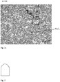
- the composition after sintering is given in Table 1, denoted FFP121, and sintered structure is shown in figure 1a .
- the material is essentially free from chromium carbide precipitations.
- the WC grain size measured as FSSS was before milling 6.25 ⁇ m. Table 1. Details on materials produced according to example 1-3. Material FFP122 FFP121 FFP256 Co (wt%) 6.09 6.17 nm Cr (wt%) - 0.59 nm C (wt%) 5.71 5.77 nm W (wt%) 88.2 87.5 nm Hc (kA/m) 9.9 9.8 6.9 Magnetic saturation (T*m 3 /kg) 112 ⁇ 10 -7 99 ⁇ 10 -7 152 ⁇ 10 -7 Density (g/cm3) 14.98 14.83 14.27 Porosity A00B00C00 A00B00C00 A00B00C00 Hv3 1402 1393 1157 K1c* 12.4 11.2 nm * Palmqvist fracture toughness according to ISO/DIS 28079
- a material with 11.0 wt% Co, 1.1 wt% Cr and balance WC was made according to established cemented carbide processes. Powders of 37.7 kg WC, 3.15 kg Co, 358 g Cr 3 C 2 and 863 g W were milled in a ball mill for in total 9 hours. During milling, 19.6 g C was added to reach the desired carbon content. The milling was carried out in wet conditions, using ethanol, with an addition of 2 wt% polyethylene glycol (PEG 40) as organic binder and 120 kg WC-Co cylpebs in a 30 litre mill. After milling, the slurry was spray-dried in N 2 -atmosphere. Green bodies were produced by uniaxial pressing and sintered by using Sinter-HIP in 55 bar Ar-pressure at 1410°C for 1 hour.
- PEG 40 polyethylene glycol
- the WC grain size measured as FSSS was before milling 15.0 ⁇ m.
- the WC grain size of the sintered materials FFP121, FFP122 and FFP256 (examples 1-3) were determined from SEM micrographs showing representative cross sections of the materials. Final step of the sample preparation was done by polishing with 1 ⁇ m diamond paste on a soft cloth followed by etching with Murakami. SEM micrographs were taken in the backscatter electron mode, magnification 2000 X, high voltage 15 kV and working distance ⁇ 10 mm.
- a material with 11.0 wt% Co, 1.1 wt% Cr and balance WC was made according to established cemented carbide processes. Powders of 87.8 g WC, 11.3 g Co, 1.28 g Cr 3 C 2 and 0.14 g C were milled in a ball mill for 8 hours. The milling was carried out in wet conditions, using ethanol, with an addition of 2 wt% polyethylene glycol (PEG 40) as organic binder and 800 g WC-Co cylpebs. After milling, the slurry was pan dried and blanks were produced by uniaxial pressing and sintered by using Sinter-HIP in 55 bar Ar-pressure at 1410°C for 1 hour.
- PEG 40 polyethylene glycol
- the sintered structure is shown in figure 1c , denoted FFP186.
- the sintered material has both chromium carbide and graphite precipitations due to excessive amount of added carbon and is thus outside the invention.
- chromium carbide precipitations could possibly be allowed provided that the content is less than 3 wt%, preferably less than 2 wt%.
- graphite precipitations are not allowed.
- the WC grain size measured as FSSS was before milling 15.0 ⁇ m.
- Drill bit inserts (rock drill buttons) were pressed and sintered according to the description in example 1 and example 2 respectively.
- the inserts were tumbled according to standard procedures known in the art and thereafter mounted into a ⁇ 48 mm drill bit with 3 front inserts ( ⁇ 9 mm, spherical front) and 9 gage inserts ( ⁇ 10 mm, spherical front).
- the carbide bits were mounted by heating the steel bit and inserting the carbide inserts.
- the bits were tested in a mine in northern Sweden.
- the test rig was an Atlas Copco twin boom Jumbo ⁇ equipped with AC2238 or AC3038 hammers. Drilling was done with one bit according to example 2 (invention, denoted FFP121) and one reference bit according to example 1 (reference, denoted FFP122) at the same time, one on each boom. After drilling roughly 20-25 meters ( ⁇ 4-5 drill holes) with each bit, the bits were switched between left and right boom to minimize the effect of varying rock conditions, and ⁇ 20-25 more meters were drilled with each bit. Then the bits were reground to regain spherical fronts, before drilling again. The bits were drilled until end of life due to too small diameter ( ⁇ 45.5 mm).
- Bit diameter wear was the main measure of carbide performance. The bit diameter was measured both before and after drilling (before grinding), all three diameters between opposed gage buttons, were measured and the largest of these three values was reported as bit diameter.
- Test results show that carbide according to the invention suffered from less wear than the reference material, see Table 3.
- FFP121 bits drilled by average 576 meters per bit compared to 449 drill meters for the reference FFP122.
- the total diameter wear during all drilling with each bit is shown in Fig. 2 . It should be noted that the diameter decrease due to grinding losses is not included.
- the reference material FFP122 was worn 0.0055 mm per drill meter while the invention FFP121 was worn only 0.0035 mm per drill meter. The numbers are inverted to obtain drilled length per mm bit wear; the reference has drilled ⁇ 183 drill meters per mm bit wear, and the invention has done -286 drill meters per mm bit wear. Table 3. Field test results of all tested bits. Bits with reference carbide according to example 1 (FFP122) Bits with carbide according to invention example 2 (FFP121) Bit no. Total drill meters (m) Total bit diameter wear during drilling (mm) Total bit diameter wear during drilling and grinding (mm) Bit no.
- Test solid rods according to reference example 1 denoted FFP122 and invention example 2, denoted FFP121 were prepared, with the exception that in this example the green bodies were pressed in a dry-bag press.
- the rods were manufactured to test the high temperature compressive creep strength of the reference, ex 1 and the invention, ex 2.
- Rock drill bit inserts ( ⁇ 10 mm, spherical front) according to example 1 and 2 have been tested in an abrasion wear test where the sample tips are worn against a rotating granite log counter surface in a turning operation.
- the load applied to each insert was 200 N
- the rotational speed was 270 rpm
- the horizontal feed rate was 0.339 mm/rev.
- the sliding distance in each test was fixed to 230 m and the sample was cooled by a continuous flow of water. Three samples per material were evaluated and each sample was carefully weighed prior and after the test. Sample volume loss was calculated from measured mass loss and sample density and serves as a measurement of wear.
- the abrasion wear test clearly shows a significantly increased wear resistance for the material according to the invention (FFP121) compared to the reference material FFP122, see results in Table 5. Table 5. Results as sample wear measured in the abrasion wear test. Sample material Volumetric wear of each specimen (mm3) Average volumetric wear (mm3) Standard deviation volumetric wear (mm3) FFP122 (According to example 1) 0.28 0.28 0.01 0.27 0.29 FFP121 (According to example 2) 0.17 0.19 0.02 0.20 0.20
Landscapes
- Engineering & Computer Science (AREA)
- Chemical & Material Sciences (AREA)
- Mechanical Engineering (AREA)
- Geology (AREA)
- Mining & Mineral Resources (AREA)
- Life Sciences & Earth Sciences (AREA)
- Materials Engineering (AREA)
- Metallurgy (AREA)
- Organic Chemistry (AREA)
- Environmental & Geological Engineering (AREA)
- Fluid Mechanics (AREA)
- Physics & Mathematics (AREA)
- General Life Sciences & Earth Sciences (AREA)
- Geochemistry & Mineralogy (AREA)
- Earth Drilling (AREA)
- Powder Metallurgy (AREA)
- Drilling Tools (AREA)
Description
- The present invention relates to rock drill buttons, comprising a body made of sintered cemented carbide that comprises hard constituents of tungsten carbide (WC) in a binder phase comprising Co, wherein the cemented carbide comprises 4-12 mass% Co and balance WC and unavoidable impurities.
- Rock drilling is a technical area in which the buttons which are used for the purpose of drilling in the rock are subjected to both severe corrosive conditions and repeated impacts due to the inherent nature of the drilling. Different drilling techniques will result in different impact loads on the buttons. Particularly severe impact conditions are found in applications such as those in which the rock drill buttons are mounted in a rock drill bit body of a top-hammer (TH) device or a down-the-hole (DTH) drilling device. The conditions to which the rock drill buttons are subjected during rock drilling also require that the rock drill buttons have a predetermined thermal conductivity in order to prevent them from attaining too high temperature.
- Traditionally, rock drill buttons may consist of a body made of sintered cemented carbide that comprises hard constituents of tungsten carbide (WC) in a binder phase comprising cobalt (Co).
- The present invention aims at investigating the possibility of adding chromium to the further components of the sintered cemented carbide, before the compaction and sintering of said carbide, and also to investigate if such further addition will require any further modification of the sintered carbide in order to obtain a functional rock drill button made thereof.
- In the technical area of cutting inserts for the cutting of metals, such as disclosed in, for example,
EP 1803830 , it has been suggested to include chromium in cutting inserts made of sintered cemented carbide comprising WC and cobalt for the purpose of reducing the grain growth of WC during the sintering process. Prevention of WC grain growth will promote the hardness and strength of the insert. However, cemented carbide having fine grained WC is not suitable for rock drilling since it is in general too brittle and has a lower thermal conductivity compared to coarse grained cemented carbide. Percussive rock drilling requires a cemented carbide which has a sufficient level of toughness. Chromium addition would be expected to, in addition to make the cemented carbide grain size smaller, also make the binder phase harder which would also reduce the overall toughness. -
US 2006/093859 A1 describes a cemented WC tool for cutting stones and discloses a Co-WC body with a low C-content and no eta-phase, comprising 9,5 wt% Co binder and WC grains with a size of 4-20 µm. It mentions the presence of Cr as a solid solution in the binder so as to improve the tool life, and discloses amounts up to 1,5 wt% of the binder. - It is an object of the present invention to present a rock drill button which is improved in comparison to rock drill buttons of prior art made of cemented carbide consisting of WC and Co in the sense that they have an improved corrosion resistance which reduces the wear in wet drilling conditions. Still the cemented carbide must have an acceptable hardness and ductility to withstand the repeated impact load that it will be subjected to during use. In other words, it must not be too brittle.
- The object of the invention is achieved by means of a rock drill button, comprising a body made of sintered cemented carbide that comprises hard constituents of tungsten carbide (WC) in a binder phase comprising Co, wherein the cemented carbide comprises 4-12 mass% Co and balance WC and unavoidable impurities, characterized in that said cemented carbide is free from any graphite and also comprises Cr in such an amount that the Cr/Co weight ratio is within the range of 0.043-0.19, and that the WC grain size mean value is above 1.75 µm. In other words, the cemented carbide consists of 4-12 mass% Co, such an amount of Cr that relation between the mass percentage of Cr and the mass percentage of Co is in the range of 0.043-0.19, and balance WC and unavoidable impurities, wherein the WC grain size mean value is above 1.75 µm (as determined with the method described in the Examples section herein). According to one embodiment the WC grain size is above 1.8µm, and according to yet another embodiment it is above 2.0 µm. Preferably, at least a major part of the rock drill button, and preferably an active part thereof aimed for engagement with the rock that is operated on, comprises cemented carbide that has the features defined hereinabove and/or hereinafter and which are essential to the present invention. According to one embodiment, the rock drill button comprises cemented carbide with the features defined hereinabove and/or hereinafter all through the body thereof. The rock drill button is produced by means of a process in which a powder comprising the elements of the cemented carbide is milled and compacted into a compact which is then sintered.
- The addition of Cr results in an improvement of the corrosion resistance of the Co-binder phase, which reduces the wear in wet drilling conditions. The Cr also makes the binder phase prone to transform from fcc to hcp during drilling that will absorb some of the energy generated in the drilling operation. The transformation will thereby harden the binder phase and reduce the wear of the button during use thereof. If the Cr/Co ratio is too low, the mentioned positive effects of Cr will be too small. If, on the other hand, the Cr/Co ratio is too high, there will be a formation of chromium carbides in which cobalt is dissolved, whereby the amount of binder phase is reduced and the cemented carbide becomes too brittle. By having a WC grain size mean value above 1.75 µm, or above 1.8 µm or above 2.0 µm, a sufficient thermal conductivity and non-brittleness of the cemented carbide is achieved. If the WC grain size is too large, the material becomes difficult to sinter. Therefore, it is preferred that the WC grain size mean value is less than 15 µm, preferably less than 10 µm.
- According to a preferred embodiment, the Cr/Co ratio is equal to or above 0.075.
- According to yet a preferred embodiment, the Cr/Co ratio is equal to or above 0.085.
- According to another preferred embodiment, the Cr/Co ratio is equal to or less than 0.15.
- According to yet another preferred embodiment, the Cr/Co ratio is equal to or less than 0.12.
- Preferably, the content of Cr in said cemented carbide is equal to or above 0.17 mass%, preferably equal to or above 0.4 mass%.
- According to yet another embodiment, the content of Cr in said cemented carbide is equal to or lower than 2.3 mass%, preferably equal to or lower than 1.2 mass%. The cobalt, forming the binder phase, should suitably be able to dissolving all the chromium present in the sintered cemented carbide at 1000 °C.
- Up to less than 3 mass%, preferably up to less than 2 mass% chromium carbides may be allowed in the cemented carbide. However, preferably, the Cr is present in the binder phase as dissolved in cobalt. Preferably, all chromium is dissolved in cobalt, and the sintered cemented carbide is essentially free from chromium carbides. Preferably, to avoid the upcoming of such chromium carbides, the Cr/Co ratio should be low enough to guarantee that the maximum content of chromium does not exceed the solubility limit of chromium in cobalt at 1000 °C. The sintered cemented carbide is free from any graphite and is preferably also free from any η-phase. In order to avoid the generation of chromium carbide or graphite in the binder phase, the amount of added carbon should be at a sufficiently low level.
- The rock drill button of the invention must not be prone to failure due to brittleness-related problems. Therefore, the cemented carbide of the rock drill button according to the invention has a hardness of not higher than 1500 HV3.
- According to one embodiment, rock drill buttons according to the invention are mounted in a rock drill bit body of a top-hammer (TH) device or a down-the-hole (DTH) drilling device. The invention also relates to a rock drill device, in particular a top-hammer device, or a down-the-hole drilling device, as well as the use of a rock drill button according to the invention in such a device.
- According to yet another embodiment, M7C3 is present in the cemented carbide. In this case M is a combination of Cr, Co and W, i.e., (Cr,Co,W)7C3. The Co solubility could reach as high as 38 at% of the metallic content in the M7C3 carbide. The exact balance of Cr:Co:W is determined by the overall carbon content of the cemented carbide. The ratio Cr/M7C3 (Cr as weight% and M7C3 as vol%) in the cemented carbide is suitably equal to or above 0.05, or equal to or above 0.1, or equal to or above 0.2, or equal to or above 0.3, or equal to or above 0.4. The ratio Cr/M7C3 (Cr as weight% and M7C3 as vol%) in the cemented carbide is suitably equal to or less than 0.5, or equal to or less than 0.4. The content of M7C3 is defined as vol% since that is how it is practically measured. Expected negative effects in rock drilling by the presence of M7C3 cannot surprisingly be seen. Such negative effects in rock drilling would have been brittleness of the cemented carbide due to the additional carbide and also reduced toughness due to the lowering of binder phase (Co) content when M7C3 is formed. Thus, the acceptable range for carbon content during production of cemented carbide can be wider since M7C3 can be accepted. This a great production advantage.
- Examples will be presented with reference to the annexed drawings, on which:
-
Figure 1a-1c show sintered structure of test sample materials denoted FFP121, FFP256 and FFP186, by means of light optical images of sample cross sections polished with conventional cemented carbide methods, wherein final polishing was done with 1 µm diamond paste on a soft cloth, -
Fig. 2 is a schematic representation of the geometry of a rock drill button used in testing, -
Fig. 3 is a diagram showing bit diameter change during drilling for reference example 1 denoted FFP122 and invention example 2, denoted FFP121, and -
Fig 4 shows creep curves for reference example 1 denoted FFP122 and invention example 2, denoted FFP121 (applied stress 900MPa, temperature 1000C). - A material with 6.0 wt% Co and balance WC was made according to established cemented carbide processes. Powders of 26.1 kg WC, 1.72 kg Co and 208 g W were milled in a ball mill for in total 11.5 hours. During milling, 16.8 g C was added to reach the desired carbon content. The milling was carried out in wet conditions, using ethanol, with an addition of 2 wt% polyethylene glycol (PEG 80) as organic binder and 120 kg WC-Co cylpebs in a 30 litre mill. After milling, the slurry was spray-dried in N2-atmosphere. Green bodies were produced by uniaxial pressing and sintered by using Sinter-HIP in 55 bar Argon-pressure at 1410°C for 1 hour.
- Details on the sintered material are shown in table 1.
- The WC grain size measured as FSSS was before milling 5.6 µm.
- A material with 6.0 wt% Co, 0.6 wt% Cr and balance WC was made according to established cemented carbide processes. Powders of 25.7 kg WC, 1.72 kg Co 195 g Cr3C2 and 380 g W were milled in a ball mill for in total 13.5 hours. During milling, 28.0 g C was added to reach the desired carbon content. The milling was carried out in wet conditions, using ethanol, with an addition of 2 wt% polyethylene glycol (PEG 80) as organic binder and 120 kg WC-Co cylpebs in a 30 litre mill. After milling, the slurry was spray-dried in N2-atmosphere. Green bodies were produced by uniaxial pressing and sintered by using Sinter-HIP in 55 bar Ar-pressure at 1410°C for 1 hour.
- The composition after sintering is given in Table 1, denoted FFP121, and sintered structure is shown in
figure 1a . The material is essentially free from chromium carbide precipitations. - The WC grain size measured as FSSS was before milling 6.25 µm.
Table 1. Details on materials produced according to example 1-3. Material FFP122 FFP121 FFP256 Co (wt%) 6.09 6.17 nm Cr (wt%) - 0.59 nm C (wt%) 5.71 5.77 nm W (wt%) 88.2 87.5 nm Hc (kA/m) 9.9 9.8 6.9 Magnetic saturation (T*m3/kg) 112∗10-7 99∗10-7 152∗10-7 Density (g/cm3) 14.98 14.83 14.27 Porosity A00B00C00 A00B00C00 A00B00C00 Hv3 1402 1393 1157 K1c* 12.4 11.2 nm * Palmqvist fracture toughness according to ISO/DIS 28079 - A material with 11.0 wt% Co, 1.1 wt% Cr and balance WC was made according to established cemented carbide processes. Powders of 37.7 kg WC, 3.15 kg Co, 358 g Cr3C2 and 863 g W were milled in a ball mill for in total 9 hours. During milling, 19.6 g C was added to reach the desired carbon content. The milling was carried out in wet conditions, using ethanol, with an addition of 2 wt% polyethylene glycol (PEG 40) as organic binder and 120 kg WC-Co cylpebs in a 30 litre mill. After milling, the slurry was spray-dried in N2-atmosphere. Green bodies were produced by uniaxial pressing and sintered by using Sinter-HIP in 55 bar Ar-pressure at 1410°C for 1 hour.
- Details on the sintered material are given in table 1 and the structure is shown in
figure 1b , denoted FFP256. The material is essentially free from chromium carbide precipitations. - The WC grain size measured as FSSS was before milling 15.0 µm.
- The WC grain size of the sintered materials FFP121, FFP122 and FFP256 (examples 1-3) were determined from SEM micrographs showing representative cross sections of the materials. Final step of the sample preparation was done by polishing with 1 µm diamond paste on a soft cloth followed by etching with Murakami. SEM micrographs were taken in the backscatter electron mode, magnification 2000 X, high voltage 15 kV and working distance ∼10 mm.
- The total area of the image surface is measured and the number of grains is manually counted. To eliminate the effect of half grains cut by the micrograph frame, all grains along two sides are included in the analysis, and grains on the two opposite sides are totally excluded from the analysis. The average grain size is calculated by multiplying the total image area with approximated volume fraction of WC and divide with the number of grains. Equivalent circle diameters (i.e. the diameter of a circle with area equivalent to the average grain size) are calculated. It should be noted that reported grain diameters are valid for random two dimensional cross sections of the grains, and is not a true diameter of the three dimensional grain. Table 2 shows the result.
Table 2. Sample material WC grain size (Equivalent circle diameter) FFP122 (According to example 1) 1.8 µm FFP121 (According to example 2) 2.1 µm FFP256 (According to example 3) 2.5 µm - A material with 11.0 wt% Co, 1.1 wt% Cr and balance WC was made according to established cemented carbide processes. Powders of 87.8 g WC, 11.3 g Co, 1.28 g Cr3C2 and 0.14 g C were milled in a ball mill for 8 hours. The milling was carried out in wet conditions, using ethanol, with an addition of 2 wt% polyethylene glycol (PEG 40) as organic binder and 800 g WC-Co cylpebs. After milling, the slurry was pan dried and blanks were produced by uniaxial pressing and sintered by using Sinter-HIP in 55 bar Ar-pressure at 1410°C for 1 hour.
- The sintered structure is shown in
figure 1c , denoted FFP186. The sintered material has both chromium carbide and graphite precipitations due to excessive amount of added carbon and is thus outside the invention. According to the invention, chromium carbide precipitations could possibly be allowed provided that the content is less than 3 wt%, preferably less than 2 wt%. However, graphite precipitations are not allowed. - The WC grain size measured as FSSS was before milling 15.0 µm.
- Drill bit inserts (rock drill buttons) were pressed and sintered according to the description in example 1 and example 2 respectively. The inserts were tumbled according to standard procedures known in the art and thereafter mounted into a Ø 48 mm drill bit with 3 front inserts (Ø9 mm, spherical front) and 9 gage inserts (Ø10 mm, spherical front). The carbide bits were mounted by heating the steel bit and inserting the carbide inserts.
- The bits were tested in a mine in northern Sweden. The test rig was an Atlas Copco twin boom Jumbo© equipped with AC2238 or AC3038 hammers. Drilling was done with one bit according to example 2 (invention, denoted FFP121) and one reference bit according to example 1 (reference, denoted FFP122) at the same time, one on each boom. After drilling roughly 20-25 meters (∼4-5 drill holes) with each bit, the bits were switched between left and right boom to minimize the effect of varying rock conditions, and ∼20-25 more meters were drilled with each bit. Then the bits were reground to regain spherical fronts, before drilling again. The bits were drilled until end of life due to too small diameter (<45.5 mm).
- Bit diameter wear was the main measure of carbide performance. The bit diameter was measured both before and after drilling (before grinding), all three diameters between opposed gage buttons, were measured and the largest of these three values was reported as bit diameter.
- Test results show that carbide according to the invention suffered from less wear than the reference material, see Table 3. FFP121 bits drilled by average 576 meters per bit compared to 449 drill meters for the reference FFP122.
- The total diameter wear during all drilling with each bit is shown in
Fig. 2 . It should be noted that the diameter decrease due to grinding losses is not included. The reference material FFP122 was worn 0.0055 mm per drill meter while the invention FFP121 was worn only 0.0035 mm per drill meter. The numbers are inverted to obtain drilled length per mm bit wear; the reference has drilled ∼183 drill meters per mm bit wear, and the invention has done -286 drill meters per mm bit wear.Table 3. Field test results of all tested bits. Bits with reference carbide according to example 1 (FFP122) Bits with carbide according to invention example 2 (FFP121) Bit no. Total drill meters (m) Total bit diameter wear during drilling (mm) Total bit diameter wear during drilling and grinding (mm) Bit no. Total drill meters (m) Total bit diameter wear during drilling (mm) Total bit diameter wear during drilling and grinding (mm) 1 507 2.27 4.43 21 598.5 1.99 4.09 2 462 2.36 3.91 22 325* 0.81 1.91 3 470 2.32 3.94 23 721.1 1.62 3.98 4 450.5 2.16 3.97 24 525.7 1.76 3.99 5 374.5 2.89 4.28 25 508.7 1.82 3.78 6 332 2.32 3.9 26 561.2 2.09 3.96 7 450.6 2.31 4.06 27 536.8 1.94 4.05 8 497.4 3.16 4.72 28 583.1 1.85 4.0 9 437.1 2.42 3.89 29 574.2 2.66 4.0 10 513.7 2.66 3.98 30 578.7 2.69 4.24 * Bit no 22 was lost due to a rod breakage and are thus excluded when calculating the average drill meters per bit. -
Fig 2 . Bit diameter change during drilling. - Test solid rods according to reference example 1 denoted FFP122 and invention example 2, denoted FFP121 were prepared, with the exception that in this example the green bodies were pressed in a dry-bag press. The rods were manufactured to test the high temperature compressive creep strength of the reference,
ex 1 and the invention,ex 2. - The temperature during testing was 1000°C and the stress was 900MPa. The following results were noted (see Table 4):
Table 4. Deformation (%) Time needed (Sec) Ref(FFP122) Invention (FFP121) 10% 850 2320 20% 1320 3220 - Totally 4 test pieces for each material were tested, two with 10% deformation and two with 20% deformation. Argon was used as protective gas.
- The results are shown in
figure 3 . The drill bit inserts according to the invention presented better performance than the drill bit inserts according to prior art. - Rock drill bit inserts (Ø10 mm, spherical front) according to example 1 and 2 have been tested in an abrasion wear test where the sample tips are worn against a rotating granite log counter surface in a turning operation. In the test the load applied to each insert was 200 N, the rotational speed was 270 rpm and the horizontal feed rate was 0.339 mm/rev. The sliding distance in each test was fixed to 230 m and the sample was cooled by a continuous flow of water. Three samples per material were evaluated and each sample was carefully weighed prior and after the test. Sample volume loss was calculated from measured mass loss and sample density and serves as a measurement of wear.
- The abrasion wear test clearly shows a significantly increased wear resistance for the material according to the invention (FFP121) compared to the reference material FFP122, see results in Table 5.
Table 5. Results as sample wear measured in the abrasion wear test. Sample material Volumetric wear of each specimen (mm3) Average volumetric wear (mm3) Standard deviation volumetric wear (mm3) FFP122 (According to example 1) 0.28 0.28 0.01 0.27 0.29 FFP121 (According to example 2) 0.17 0.19 0.02 0.20 0.20
Claims (11)
- A rock drill button, comprising a body made of sintered cemented carbide that comprises hard constituents of tungsten carbide (WC) in a binder phase comprising Co, wherein the cemented carbide comprises
4-12 mass% Co, Cr, and
balance WC and unavoidable impurities,
characterized in that said cemented carbide comprises Cr in such an amount that the Cr/Co weight ratio is within the range of 0.043-0.19, the WC grain size mean value is above 1.75 µm, and the cemented carbide is free from any graphite. - A rock drill button according to claim 1, characterized in that the WC grain size mean value is above 2.0 µm.
- A rock drill button according to claim 1 or 2, characterized in that the Cr/Co weight ratio is equal to or above 0.075.
- A rock drill button according to claim 1 or 2, characterized in that the Cr/Co weight ratio is equal to or above 0.085.
- A rock drill button according to any one of claims 1-4, characterized in that the Cr/Co weight ratio is equal to or less than 0.15.
- A rock drill button according to any one of claims 1-4, characterized in that the Cr/Co weight ratio is equal to or less than 0.12.
- A rock drill button according to any one of claims 1-6, characterized in that the content of Cr in said cemented carbide is equal to or above 0.17 mass%, preferably equal to or above 0.4 mass%.
- A rock drill button according to any one of claims 1-6, characterized in that the content of Cr in said cemented carbide is equal to or lower than 2.3 mass%, preferably equal to or lower than 1.2 mass%.
- A rock drill button according to any one of claims 1-8, characterized in that the Cr is present in the binder phase as dissolved in cobalt.
- A rock drill button according to any one of claims 1-9, characterized in that the binder phase is essentially free from chromium carbide.
- A rock drill button according to any one of claims 1-10, characterized in that said cemented carbide has a hardness of not higher than 1500 HV3.
Priority Applications (1)
| Application Number | Priority Date | Filing Date | Title |
|---|---|---|---|
| PL16713359T PL3274482T3 (en) | 2015-03-26 | 2016-03-23 | A rock drill button |
Applications Claiming Priority (2)
| Application Number | Priority Date | Filing Date | Title |
|---|---|---|---|
| EP15160962 | 2015-03-26 | ||
| PCT/EP2016/056403 WO2016151025A1 (en) | 2015-03-26 | 2016-03-23 | A rock drill button |
Publications (2)
| Publication Number | Publication Date |
|---|---|
| EP3274482A1 EP3274482A1 (en) | 2018-01-31 |
| EP3274482B1 true EP3274482B1 (en) | 2019-09-18 |
Family
ID=52779539
Family Applications (1)
| Application Number | Title | Priority Date | Filing Date |
|---|---|---|---|
| EP16713359.4A Active EP3274482B1 (en) | 2015-03-26 | 2016-03-23 | A rock drill button |
Country Status (15)
| Country | Link |
|---|---|
| US (1) | US10895001B2 (en) |
| EP (1) | EP3274482B1 (en) |
| CN (1) | CN107636249B (en) |
| AU (1) | AU2016236146B2 (en) |
| BR (1) | BR112017020529B1 (en) |
| CA (1) | CA2979505C (en) |
| CL (1) | CL2017002412A1 (en) |
| DK (1) | DK3274482T3 (en) |
| ES (1) | ES2761625T3 (en) |
| MX (1) | MX380025B (en) |
| PE (1) | PE20180109A1 (en) |
| PL (1) | PL3274482T3 (en) |
| RU (1) | RU2719867C2 (en) |
| WO (1) | WO2016151025A1 (en) |
| ZA (1) | ZA201706160B (en) |
Families Citing this family (8)
| Publication number | Priority date | Publication date | Assignee | Title |
|---|---|---|---|---|
| SE541073C2 (en) * | 2016-11-18 | 2019-03-26 | Epiroc Drilling Tools Ab | Drill bit insert for percussive rock drilling |
| ES2947357T3 (en) * | 2018-03-27 | 2023-08-07 | Sandvik Mining And Construction Tools Ab | rock drilling insert |
| EP3899079B1 (en) * | 2018-12-20 | 2025-06-04 | AB Sandvik Coromant | Coated cutting tool |
| ES2912991T3 (en) * | 2019-07-10 | 2022-05-30 | Sandvik Mining And Construction Tools Ab | Gradient cemented carbide body and manufacturing method thereof |
| WO2022146214A1 (en) * | 2020-12-30 | 2022-07-07 | Epiroc Drilling Tools Aktiebolag | Rock drill insert and method for manufacturing a rock drill insert |
| CN114147228B (en) * | 2021-11-03 | 2024-02-13 | 浙江恒成硬质合金有限公司 | Preparation method of hard alloy top hammer mixture |
| CN115845734B (en) * | 2022-07-12 | 2026-03-17 | 株洲硬质合金集团有限公司 | A six-sided impact-resistant cemented carbide hammer, its preparation method and application |
| CN116752024A (en) * | 2023-08-21 | 2023-09-15 | 包头市新盛粉末冶金制品科技有限公司 | Tungsten carbide super wear-resistant hard alloy and preparation method and application thereof |
Family Cites Families (17)
| Publication number | Priority date | Publication date | Assignee | Title |
|---|---|---|---|---|
| SE9004123D0 (en) * | 1990-12-21 | 1990-12-21 | Sandvik Ab | DIAMOND IMPREGNERATED HARD MATERIAL |
| US5305840A (en) * | 1992-09-14 | 1994-04-26 | Smith International, Inc. | Rock bit with cobalt alloy cemented tungsten carbide inserts |
| DE19907749A1 (en) * | 1999-02-23 | 2000-08-24 | Kennametal Inc | Sintered hard metal body useful as cutter insert or throwaway cutter tip has concentration gradient of stress-induced phase transformation-free face-centered cubic cobalt-nickel-iron binder |
| SE519005C2 (en) * | 1999-03-26 | 2002-12-17 | Sandvik Ab | Coated cemented carbide inserts |
| ATE275211T1 (en) * | 1999-10-12 | 2004-09-15 | Ceratizit Austria Gmbh | CARBIDE ALLOY FOR SHAPING USING EDM MACHINING PROCESS |
| US6660133B2 (en) * | 2002-03-14 | 2003-12-09 | Kennametal Inc. | Nanolayered coated cutting tool and method for making the same |
| US20060093859A1 (en) | 2002-07-10 | 2006-05-04 | Igor Konyashin | Hard metal, in particular for cutting stone, concrete, and asphalt |
| JP3762777B1 (en) | 2004-10-19 | 2006-04-05 | 住友電気工業株式会社 | Cemented carbide |
| JP5023448B2 (en) * | 2005-07-27 | 2012-09-12 | 株式会社タンガロイ | cBN tool |
| RU53354U1 (en) * | 2005-11-16 | 2006-05-10 | Лев Христофорович Балдаев | SHAROSHKA |
| SE0602812L (en) * | 2006-12-27 | 2008-06-28 | Sandvik Intellectual Property | CVD coated cemented carbide inserts for toughness requiring short hole drilling operations |
| SE0701320L (en) * | 2007-06-01 | 2008-12-02 | Sandvik Intellectual Property | Coated cemented carbide for mold tool applications |
| JP5462549B2 (en) | 2009-08-20 | 2014-04-02 | 住友電気工業株式会社 | Cemented carbide |
| EP2434086B1 (en) * | 2010-09-22 | 2013-05-15 | Sandvik Intellectual Property AB | A rock drill bit and a drilling assembly for percussive rock drilling |
| GB201108975D0 (en) * | 2011-05-27 | 2011-07-13 | Element Six Ltd | Superhard structure, tool element and method of making same |
| EP2768995B1 (en) * | 2011-10-17 | 2017-01-04 | Sandvik Intellectual Property AB | Method of making a cemented carbide or cermet powder by using a resonant acoustic mixer |
| JP5152770B1 (en) * | 2012-02-20 | 2013-02-27 | 有限会社Mts | Method for producing tough cemented carbide |
-
2016
- 2016-03-23 US US15/561,059 patent/US10895001B2/en active Active
- 2016-03-23 BR BR112017020529-7A patent/BR112017020529B1/en active IP Right Grant
- 2016-03-23 CA CA2979505A patent/CA2979505C/en active Active
- 2016-03-23 PL PL16713359T patent/PL3274482T3/en unknown
- 2016-03-23 MX MX2017012209A patent/MX380025B/en unknown
- 2016-03-23 ES ES16713359T patent/ES2761625T3/en active Active
- 2016-03-23 WO PCT/EP2016/056403 patent/WO2016151025A1/en not_active Ceased
- 2016-03-23 AU AU2016236146A patent/AU2016236146B2/en active Active
- 2016-03-23 DK DK16713359.4T patent/DK3274482T3/en active
- 2016-03-23 CN CN201680018387.0A patent/CN107636249B/en active Active
- 2016-03-23 EP EP16713359.4A patent/EP3274482B1/en active Active
- 2016-03-23 PE PE2017001589A patent/PE20180109A1/en unknown
- 2016-03-23 RU RU2017134653A patent/RU2719867C2/en active
-
2017
- 2017-09-11 ZA ZA2017/06160A patent/ZA201706160B/en unknown
- 2017-09-25 CL CL2017002412A patent/CL2017002412A1/en unknown
Non-Patent Citations (1)
| Title |
|---|
| None * |
Also Published As
| Publication number | Publication date |
|---|---|
| CA2979505A1 (en) | 2016-09-29 |
| CN107636249A (en) | 2018-01-26 |
| CL2017002412A1 (en) | 2018-03-16 |
| PE20180109A1 (en) | 2018-01-18 |
| US20180073108A1 (en) | 2018-03-15 |
| ES2761625T3 (en) | 2020-05-20 |
| DK3274482T3 (en) | 2020-01-06 |
| WO2016151025A1 (en) | 2016-09-29 |
| AU2016236146B2 (en) | 2020-09-03 |
| CN107636249B (en) | 2020-10-30 |
| RU2017134653A (en) | 2019-04-05 |
| EP3274482A1 (en) | 2018-01-31 |
| BR112017020529A2 (en) | 2018-07-10 |
| PL3274482T3 (en) | 2020-06-15 |
| RU2017134653A3 (en) | 2019-09-25 |
| ZA201706160B (en) | 2022-08-31 |
| AU2016236146A1 (en) | 2017-09-28 |
| BR112017020529B1 (en) | 2021-10-19 |
| MX380025B (en) | 2025-03-11 |
| RU2719867C2 (en) | 2020-04-23 |
| US10895001B2 (en) | 2021-01-19 |
| MX2017012209A (en) | 2018-01-23 |
| CA2979505C (en) | 2023-07-04 |
Similar Documents
| Publication | Publication Date | Title |
|---|---|---|
| US10895001B2 (en) | Rock drill button | |
| EP3808867B1 (en) | A rock drill insert | |
| KR20110079901A (en) | Molybdenum-containing metal powder for the production of cemented carbide based on tungsten carbide | |
| US10336654B2 (en) | Cemented carbide with cobalt-molybdenum alloy binder | |
| US20220001445A1 (en) | Binder redistribution within a cemented carbide mining insert | |
| US20110195834A1 (en) | Wear Resistant Two-Phase Binderless Tungsten Carbide and Method of Making Same | |
| US20060093859A1 (en) | Hard metal, in particular for cutting stone, concrete, and asphalt | |
| WO2021005076A1 (en) | Gradient cemented carbide body and method of manufacturing thereof | |
| US20240287655A1 (en) | Cemented carbide material, a polycrystalline diamond construction including cemented carbide material and method of making same | |
| EP3542021B1 (en) | Drill bit insert for rock drilling | |
| US20240295012A1 (en) | Cemented carbide insert for mining or cutting applications comprising gamma phase carbide | |
| EP4555115B1 (en) | Rock drill insert | |
| OA21468A (en) | Cemented carbide insert for mining or cutting applications comprising gamma phase carbide | |
| OA20192A (en) | Binder redistribution within a cemented carbide mining insert. |
Legal Events
| Date | Code | Title | Description |
|---|---|---|---|
| STAA | Information on the status of an ep patent application or granted ep patent |
Free format text: STATUS: THE INTERNATIONAL PUBLICATION HAS BEEN MADE |
|
| PUAI | Public reference made under article 153(3) epc to a published international application that has entered the european phase |
Free format text: ORIGINAL CODE: 0009012 |
|
| STAA | Information on the status of an ep patent application or granted ep patent |
Free format text: STATUS: REQUEST FOR EXAMINATION WAS MADE |
|
| 17P | Request for examination filed |
Effective date: 20171026 |
|
| AK | Designated contracting states |
Kind code of ref document: A1 Designated state(s): AL AT BE BG CH CY CZ DE DK EE ES FI FR GB GR HR HU IE IS IT LI LT LU LV MC MK MT NL NO PL PT RO RS SE SI SK SM TR |
|
| AX | Request for extension of the european patent |
Extension state: BA ME |
|
| DAV | Request for validation of the european patent (deleted) | ||
| DAX | Request for extension of the european patent (deleted) | ||
| GRAP | Despatch of communication of intention to grant a patent |
Free format text: ORIGINAL CODE: EPIDOSNIGR1 |
|
| STAA | Information on the status of an ep patent application or granted ep patent |
Free format text: STATUS: GRANT OF PATENT IS INTENDED |
|
| INTG | Intention to grant announced |
Effective date: 20190417 |
|
| GRAS | Grant fee paid |
Free format text: ORIGINAL CODE: EPIDOSNIGR3 |
|
| GRAA | (expected) grant |
Free format text: ORIGINAL CODE: 0009210 |
|
| STAA | Information on the status of an ep patent application or granted ep patent |
Free format text: STATUS: THE PATENT HAS BEEN GRANTED |
|
| AK | Designated contracting states |
Kind code of ref document: B1 Designated state(s): AL AT BE BG CH CY CZ DE DK EE ES FI FR GB GR HR HU IE IS IT LI LT LU LV MC MK MT NL NO PL PT RO RS SE SI SK SM TR |
|
| REG | Reference to a national code |
Ref country code: GB Ref legal event code: FG4D |
|
| REG | Reference to a national code |
Ref country code: CH Ref legal event code: EP |
|
| REG | Reference to a national code |
Ref country code: DE Ref legal event code: R096 Ref document number: 602016020808 Country of ref document: DE |
|
| REG | Reference to a national code |
Ref country code: AT Ref legal event code: REF Ref document number: 1181393 Country of ref document: AT Kind code of ref document: T Effective date: 20191015 |
|
| REG | Reference to a national code |
Ref country code: IE Ref legal event code: FG4D |
|
| REG | Reference to a national code |
Ref country code: SE Ref legal event code: TRGR |
|
| REG | Reference to a national code |
Ref country code: DK Ref legal event code: T3 Effective date: 20191218 |
|
| REG | Reference to a national code |
Ref country code: NL Ref legal event code: MP Effective date: 20190918 |
|
| REG | Reference to a national code |
Ref country code: NO Ref legal event code: T2 Effective date: 20190918 |
|
| PG25 | Lapsed in a contracting state [announced via postgrant information from national office to epo] |
Ref country code: BG Free format text: LAPSE BECAUSE OF FAILURE TO SUBMIT A TRANSLATION OF THE DESCRIPTION OR TO PAY THE FEE WITHIN THE PRESCRIBED TIME-LIMIT Effective date: 20191218 Ref country code: HR Free format text: LAPSE BECAUSE OF FAILURE TO SUBMIT A TRANSLATION OF THE DESCRIPTION OR TO PAY THE FEE WITHIN THE PRESCRIBED TIME-LIMIT Effective date: 20190918 Ref country code: LT Free format text: LAPSE BECAUSE OF FAILURE TO SUBMIT A TRANSLATION OF THE DESCRIPTION OR TO PAY THE FEE WITHIN THE PRESCRIBED TIME-LIMIT Effective date: 20190918 |
|
| REG | Reference to a national code |
Ref country code: LT Ref legal event code: MG4D |
|
| PG25 | Lapsed in a contracting state [announced via postgrant information from national office to epo] |
Ref country code: AL Free format text: LAPSE BECAUSE OF FAILURE TO SUBMIT A TRANSLATION OF THE DESCRIPTION OR TO PAY THE FEE WITHIN THE PRESCRIBED TIME-LIMIT Effective date: 20190918 Ref country code: GR Free format text: LAPSE BECAUSE OF FAILURE TO SUBMIT A TRANSLATION OF THE DESCRIPTION OR TO PAY THE FEE WITHIN THE PRESCRIBED TIME-LIMIT Effective date: 20191219 Ref country code: LV Free format text: LAPSE BECAUSE OF FAILURE TO SUBMIT A TRANSLATION OF THE DESCRIPTION OR TO PAY THE FEE WITHIN THE PRESCRIBED TIME-LIMIT Effective date: 20190918 Ref country code: RS Free format text: LAPSE BECAUSE OF FAILURE TO SUBMIT A TRANSLATION OF THE DESCRIPTION OR TO PAY THE FEE WITHIN THE PRESCRIBED TIME-LIMIT Effective date: 20190918 |
|
| PG25 | Lapsed in a contracting state [announced via postgrant information from national office to epo] |
Ref country code: RO Free format text: LAPSE BECAUSE OF FAILURE TO SUBMIT A TRANSLATION OF THE DESCRIPTION OR TO PAY THE FEE WITHIN THE PRESCRIBED TIME-LIMIT Effective date: 20190918 Ref country code: NL Free format text: LAPSE BECAUSE OF FAILURE TO SUBMIT A TRANSLATION OF THE DESCRIPTION OR TO PAY THE FEE WITHIN THE PRESCRIBED TIME-LIMIT Effective date: 20190918 Ref country code: PT Free format text: LAPSE BECAUSE OF FAILURE TO SUBMIT A TRANSLATION OF THE DESCRIPTION OR TO PAY THE FEE WITHIN THE PRESCRIBED TIME-LIMIT Effective date: 20200120 Ref country code: EE Free format text: LAPSE BECAUSE OF FAILURE TO SUBMIT A TRANSLATION OF THE DESCRIPTION OR TO PAY THE FEE WITHIN THE PRESCRIBED TIME-LIMIT Effective date: 20190918 |
|
| REG | Reference to a national code |
Ref country code: ES Ref legal event code: FG2A Ref document number: 2761625 Country of ref document: ES Kind code of ref document: T3 Effective date: 20200520 |
|
| PG25 | Lapsed in a contracting state [announced via postgrant information from national office to epo] |
Ref country code: SK Free format text: LAPSE BECAUSE OF FAILURE TO SUBMIT A TRANSLATION OF THE DESCRIPTION OR TO PAY THE FEE WITHIN THE PRESCRIBED TIME-LIMIT Effective date: 20190918 Ref country code: CZ Free format text: LAPSE BECAUSE OF FAILURE TO SUBMIT A TRANSLATION OF THE DESCRIPTION OR TO PAY THE FEE WITHIN THE PRESCRIBED TIME-LIMIT Effective date: 20190918 Ref country code: SM Free format text: LAPSE BECAUSE OF FAILURE TO SUBMIT A TRANSLATION OF THE DESCRIPTION OR TO PAY THE FEE WITHIN THE PRESCRIBED TIME-LIMIT Effective date: 20190918 Ref country code: IS Free format text: LAPSE BECAUSE OF FAILURE TO SUBMIT A TRANSLATION OF THE DESCRIPTION OR TO PAY THE FEE WITHIN THE PRESCRIBED TIME-LIMIT Effective date: 20200224 |
|
| REG | Reference to a national code |
Ref country code: DE Ref legal event code: R097 Ref document number: 602016020808 Country of ref document: DE |
|
| PLBE | No opposition filed within time limit |
Free format text: ORIGINAL CODE: 0009261 |
|
| STAA | Information on the status of an ep patent application or granted ep patent |
Free format text: STATUS: NO OPPOSITION FILED WITHIN TIME LIMIT |
|
| PG2D | Information on lapse in contracting state deleted |
Ref country code: IS |
|
| PG25 | Lapsed in a contracting state [announced via postgrant information from national office to epo] |
Ref country code: IS Free format text: LAPSE BECAUSE OF FAILURE TO SUBMIT A TRANSLATION OF THE DESCRIPTION OR TO PAY THE FEE WITHIN THE PRESCRIBED TIME-LIMIT Effective date: 20200119 |
|
| 26N | No opposition filed |
Effective date: 20200619 |
|
| PG25 | Lapsed in a contracting state [announced via postgrant information from national office to epo] |
Ref country code: SI Free format text: LAPSE BECAUSE OF FAILURE TO SUBMIT A TRANSLATION OF THE DESCRIPTION OR TO PAY THE FEE WITHIN THE PRESCRIBED TIME-LIMIT Effective date: 20190918 |
|
| PG25 | Lapsed in a contracting state [announced via postgrant information from national office to epo] |
Ref country code: MC Free format text: LAPSE BECAUSE OF FAILURE TO SUBMIT A TRANSLATION OF THE DESCRIPTION OR TO PAY THE FEE WITHIN THE PRESCRIBED TIME-LIMIT Effective date: 20190918 |
|
| REG | Reference to a national code |
Ref country code: CH Ref legal event code: PL |
|
| REG | Reference to a national code |
Ref country code: BE Ref legal event code: MM Effective date: 20200331 |
|
| PG25 | Lapsed in a contracting state [announced via postgrant information from national office to epo] |
Ref country code: LU Free format text: LAPSE BECAUSE OF NON-PAYMENT OF DUE FEES Effective date: 20200323 |
|
| PG25 | Lapsed in a contracting state [announced via postgrant information from national office to epo] |
Ref country code: IE Free format text: LAPSE BECAUSE OF NON-PAYMENT OF DUE FEES Effective date: 20200323 Ref country code: LI Free format text: LAPSE BECAUSE OF NON-PAYMENT OF DUE FEES Effective date: 20200331 Ref country code: CH Free format text: LAPSE BECAUSE OF NON-PAYMENT OF DUE FEES Effective date: 20200331 |
|
| PG25 | Lapsed in a contracting state [announced via postgrant information from national office to epo] |
Ref country code: BE Free format text: LAPSE BECAUSE OF NON-PAYMENT OF DUE FEES Effective date: 20200331 |
|
| REG | Reference to a national code |
Ref country code: AT Ref legal event code: UEP Ref document number: 1181393 Country of ref document: AT Kind code of ref document: T Effective date: 20190918 |
|
| PG25 | Lapsed in a contracting state [announced via postgrant information from national office to epo] |
Ref country code: MT Free format text: LAPSE BECAUSE OF FAILURE TO SUBMIT A TRANSLATION OF THE DESCRIPTION OR TO PAY THE FEE WITHIN THE PRESCRIBED TIME-LIMIT Effective date: 20190918 Ref country code: CY Free format text: LAPSE BECAUSE OF FAILURE TO SUBMIT A TRANSLATION OF THE DESCRIPTION OR TO PAY THE FEE WITHIN THE PRESCRIBED TIME-LIMIT Effective date: 20190918 |
|
| PG25 | Lapsed in a contracting state [announced via postgrant information from national office to epo] |
Ref country code: MK Free format text: LAPSE BECAUSE OF FAILURE TO SUBMIT A TRANSLATION OF THE DESCRIPTION OR TO PAY THE FEE WITHIN THE PRESCRIBED TIME-LIMIT Effective date: 20190918 |
|
| PGFP | Annual fee paid to national office [announced via postgrant information from national office to epo] |
Ref country code: ES Payment date: 20250408 Year of fee payment: 10 |
|
| PGFP | Annual fee paid to national office [announced via postgrant information from national office to epo] |
Ref country code: SE Payment date: 20260211 Year of fee payment: 11 |
|
| PGFP | Annual fee paid to national office [announced via postgrant information from national office to epo] |
Ref country code: GB Payment date: 20260202 Year of fee payment: 11 |
|
| PGFP | Annual fee paid to national office [announced via postgrant information from national office to epo] |
Ref country code: NO Payment date: 20260310 Year of fee payment: 11 Ref country code: DE Payment date: 20260204 Year of fee payment: 11 Ref country code: DK Payment date: 20260313 Year of fee payment: 11 |
|
| PGFP | Annual fee paid to national office [announced via postgrant information from national office to epo] |
Ref country code: AT Payment date: 20260225 Year of fee payment: 11 |
|
| PGFP | Annual fee paid to national office [announced via postgrant information from national office to epo] |
Ref country code: FI Payment date: 20260312 Year of fee payment: 11 Ref country code: IT Payment date: 20260220 Year of fee payment: 11 |
|
| PGFP | Annual fee paid to national office [announced via postgrant information from national office to epo] |
Ref country code: FR Payment date: 20260223 Year of fee payment: 11 |
|
| PGFP | Annual fee paid to national office [announced via postgrant information from national office to epo] |
Ref country code: TR Payment date: 20260318 Year of fee payment: 11 |
|
| PGFP | Annual fee paid to national office [announced via postgrant information from national office to epo] |
Ref country code: PL Payment date: 20260212 Year of fee payment: 11 |