EP3274308B1 - High strength, scratch resistant and transparent glass-based materials - Google Patents
High strength, scratch resistant and transparent glass-based materials Download PDFInfo
- Publication number
- EP3274308B1 EP3274308B1 EP16714689.3A EP16714689A EP3274308B1 EP 3274308 B1 EP3274308 B1 EP 3274308B1 EP 16714689 A EP16714689 A EP 16714689A EP 3274308 B1 EP3274308 B1 EP 3274308B1
- Authority
- EP
- European Patent Office
- Prior art keywords
- glass
- based material
- phase
- mol
- range
- Prior art date
- Legal status (The legal status is an assumption and is not a legal conclusion. Google has not performed a legal analysis and makes no representation as to the accuracy of the status listed.)
- Active
Links
- 239000011521 glass Substances 0.000 title claims description 283
- 239000000463 material Substances 0.000 title claims description 226
- 230000003678 scratch resistant effect Effects 0.000 title description 2
- 238000012360 testing method Methods 0.000 claims description 59
- VYPSYNLAJGMNEJ-UHFFFAOYSA-N Silicium dioxide Chemical compound O=[Si]=O VYPSYNLAJGMNEJ-UHFFFAOYSA-N 0.000 claims description 22
- 239000013078 crystal Substances 0.000 claims description 20
- PNEYBMLMFCGWSK-UHFFFAOYSA-N aluminium oxide Inorganic materials [O-2].[O-2].[O-2].[Al+3].[Al+3] PNEYBMLMFCGWSK-UHFFFAOYSA-N 0.000 claims description 14
- 229910003460 diamond Inorganic materials 0.000 claims description 13
- 239000010432 diamond Substances 0.000 claims description 13
- KZHJGOXRZJKJNY-UHFFFAOYSA-N dioxosilane;oxo(oxoalumanyloxy)alumane Chemical compound O=[Si]=O.O=[Si]=O.O=[Al]O[Al]=O.O=[Al]O[Al]=O.O=[Al]O[Al]=O KZHJGOXRZJKJNY-UHFFFAOYSA-N 0.000 claims description 10
- 150000002500 ions Chemical group 0.000 claims description 10
- 238000002834 transmittance Methods 0.000 claims description 10
- 229910000500 β-quartz Inorganic materials 0.000 claims description 9
- 239000003082 abrasive agent Substances 0.000 claims description 8
- 229910052863 mullite Inorganic materials 0.000 claims description 8
- 239000002245 particle Substances 0.000 claims description 8
- WHXSMMKQMYFTQS-UHFFFAOYSA-N Lithium Chemical compound [Li] WHXSMMKQMYFTQS-UHFFFAOYSA-N 0.000 claims description 7
- 229910052744 lithium Inorganic materials 0.000 claims description 7
- 238000001429 visible spectrum Methods 0.000 claims description 7
- 238000002441 X-ray diffraction Methods 0.000 claims description 6
- 230000004083 survival effect Effects 0.000 claims description 6
- 238000003991 Rietveld refinement Methods 0.000 claims description 5
- 239000000835 fiber Substances 0.000 claims description 5
- 229910052664 nepheline Inorganic materials 0.000 claims description 5
- 239000010434 nepheline Substances 0.000 claims description 5
- 239000002159 nanocrystal Substances 0.000 claims description 4
- 238000005299 abrasion Methods 0.000 claims description 3
- CNLWCVNCHLKFHK-UHFFFAOYSA-N aluminum;lithium;dioxido(oxo)silane Chemical compound [Li+].[Al+3].[O-][Si]([O-])=O.[O-][Si]([O-])=O CNLWCVNCHLKFHK-UHFFFAOYSA-N 0.000 claims description 3
- 229910052596 spinel Inorganic materials 0.000 claims description 3
- 239000011029 spinel Substances 0.000 claims description 3
- 229910052644 β-spodumene Inorganic materials 0.000 claims description 3
- 239000005358 alkali aluminosilicate glass Substances 0.000 claims description 2
- HEHRHMRHPUNLIR-UHFFFAOYSA-N aluminum;hydroxy-[hydroxy(oxo)silyl]oxy-oxosilane;lithium Chemical compound [Li].[Al].O[Si](=O)O[Si](O)=O.O[Si](=O)O[Si](O)=O HEHRHMRHPUNLIR-UHFFFAOYSA-N 0.000 claims description 2
- 229910052661 anorthite Inorganic materials 0.000 claims description 2
- 230000005540 biological transmission Effects 0.000 claims description 2
- GWWPLLOVYSCJIO-UHFFFAOYSA-N dialuminum;calcium;disilicate Chemical compound [Al+3].[Al+3].[Ca+2].[O-][Si]([O-])([O-])[O-].[O-][Si]([O-])([O-])[O-] GWWPLLOVYSCJIO-UHFFFAOYSA-N 0.000 claims description 2
- 229910052670 petalite Inorganic materials 0.000 claims description 2
- 239000005368 silicate glass Substances 0.000 claims description 2
- 239000005361 soda-lime glass Substances 0.000 claims description 2
- 239000011222 crystalline ceramic Substances 0.000 claims 2
- 229910002106 crystalline ceramic Inorganic materials 0.000 claims 2
- 230000000717 retained effect Effects 0.000 claims 2
- WVMPCBWWBLZKPD-UHFFFAOYSA-N dilithium oxido-[oxido(oxo)silyl]oxy-oxosilane Chemical compound [Li+].[Li+].[O-][Si](=O)O[Si]([O-])=O WVMPCBWWBLZKPD-UHFFFAOYSA-N 0.000 claims 1
- 230000000063 preceeding effect Effects 0.000 claims 1
- 239000000203 mixture Substances 0.000 description 30
- 238000000034 method Methods 0.000 description 24
- 230000035882 stress Effects 0.000 description 22
- 238000005342 ion exchange Methods 0.000 description 19
- 150000003839 salts Chemical class 0.000 description 19
- MCMNRKCIXSYSNV-UHFFFAOYSA-N Zirconium dioxide Chemical compound O=[Zr]=O MCMNRKCIXSYSNV-UHFFFAOYSA-N 0.000 description 15
- 238000003279 ceramming Methods 0.000 description 14
- XOLBLPGZBRYERU-UHFFFAOYSA-N tin dioxide Chemical compound O=[Sn]=O XOLBLPGZBRYERU-UHFFFAOYSA-N 0.000 description 14
- BASFCYQUMIYNBI-UHFFFAOYSA-N platinum Chemical compound [Pt] BASFCYQUMIYNBI-UHFFFAOYSA-N 0.000 description 12
- 238000007654 immersion Methods 0.000 description 10
- 239000000758 substrate Substances 0.000 description 10
- KKCBUQHMOMHUOY-UHFFFAOYSA-N Na2O Inorganic materials [O-2].[Na+].[Na+] KKCBUQHMOMHUOY-UHFFFAOYSA-N 0.000 description 8
- 229910052681 coesite Inorganic materials 0.000 description 8
- 230000006835 compression Effects 0.000 description 8
- 238000007906 compression Methods 0.000 description 8
- 229910052593 corundum Inorganic materials 0.000 description 8
- 229910052906 cristobalite Inorganic materials 0.000 description 8
- 230000006378 damage Effects 0.000 description 8
- 239000010410 layer Substances 0.000 description 8
- INHCSSUBVCNVSK-UHFFFAOYSA-L lithium sulfate Chemical compound [Li+].[Li+].[O-]S([O-])(=O)=O INHCSSUBVCNVSK-UHFFFAOYSA-L 0.000 description 8
- 239000000377 silicon dioxide Substances 0.000 description 8
- 229910052682 stishovite Inorganic materials 0.000 description 8
- 238000005728 strengthening Methods 0.000 description 8
- 229910052905 tridymite Inorganic materials 0.000 description 8
- 229910001845 yogo sapphire Inorganic materials 0.000 description 8
- 238000007373 indentation Methods 0.000 description 7
- 230000008569 process Effects 0.000 description 7
- FUJCRWPEOMXPAD-UHFFFAOYSA-N Li2O Inorganic materials [Li+].[Li+].[O-2] FUJCRWPEOMXPAD-UHFFFAOYSA-N 0.000 description 6
- XUCJHNOBJLKZNU-UHFFFAOYSA-M dilithium;hydroxide Chemical compound [Li+].[Li+].[OH-] XUCJHNOBJLKZNU-UHFFFAOYSA-M 0.000 description 6
- 229910052697 platinum Inorganic materials 0.000 description 6
- 238000005452 bending Methods 0.000 description 5
- 238000005259 measurement Methods 0.000 description 5
- OTYBMLCTZGSZBG-UHFFFAOYSA-L potassium sulfate Chemical compound [K+].[K+].[O-]S([O-])(=O)=O OTYBMLCTZGSZBG-UHFFFAOYSA-L 0.000 description 5
- 229910052939 potassium sulfate Inorganic materials 0.000 description 5
- 239000007787 solid Substances 0.000 description 5
- 230000000052 comparative effect Effects 0.000 description 4
- FGIUAXJPYTZDNR-UHFFFAOYSA-N potassium nitrate Chemical compound [K+].[O-][N+]([O-])=O FGIUAXJPYTZDNR-UHFFFAOYSA-N 0.000 description 4
- 238000007679 ring-on-ring test Methods 0.000 description 4
- ZLMJMSJWJFRBEC-UHFFFAOYSA-N Potassium Chemical compound [K] ZLMJMSJWJFRBEC-UHFFFAOYSA-N 0.000 description 3
- 238000007545 Vickers hardness test Methods 0.000 description 3
- 239000002390 adhesive tape Substances 0.000 description 3
- -1 but not limited to Chemical class 0.000 description 3
- 238000003426 chemical strengthening reaction Methods 0.000 description 3
- 230000000694 effects Effects 0.000 description 3
- 230000001747 exhibiting effect Effects 0.000 description 3
- 239000012634 fragment Substances 0.000 description 3
- 230000007246 mechanism Effects 0.000 description 3
- 238000001000 micrograph Methods 0.000 description 3
- 230000006911 nucleation Effects 0.000 description 3
- 238000010899 nucleation Methods 0.000 description 3
- 239000011591 potassium Substances 0.000 description 3
- 229910052700 potassium Inorganic materials 0.000 description 3
- 239000002994 raw material Substances 0.000 description 3
- HBMJWWWQQXIZIP-UHFFFAOYSA-N silicon carbide Chemical compound [Si+]#[C-] HBMJWWWQQXIZIP-UHFFFAOYSA-N 0.000 description 3
- 239000006058 strengthened glass Substances 0.000 description 3
- OKTJSMMVPCPJKN-UHFFFAOYSA-N Carbon Chemical compound [C] OKTJSMMVPCPJKN-UHFFFAOYSA-N 0.000 description 2
- KRHYYFGTRYWZRS-UHFFFAOYSA-N Fluorane Chemical compound F KRHYYFGTRYWZRS-UHFFFAOYSA-N 0.000 description 2
- FYYHWMGAXLPEAU-UHFFFAOYSA-N Magnesium Chemical compound [Mg] FYYHWMGAXLPEAU-UHFFFAOYSA-N 0.000 description 2
- WCUXLLCKKVVCTQ-UHFFFAOYSA-M Potassium chloride Chemical compound [Cl-].[K+] WCUXLLCKKVVCTQ-UHFFFAOYSA-M 0.000 description 2
- 229910000831 Steel Inorganic materials 0.000 description 2
- GWEVSGVZZGPLCZ-UHFFFAOYSA-N Titan oxide Chemical compound O=[Ti]=O GWEVSGVZZGPLCZ-UHFFFAOYSA-N 0.000 description 2
- 229910052783 alkali metal Inorganic materials 0.000 description 2
- 238000005280 amorphization Methods 0.000 description 2
- 238000000137 annealing Methods 0.000 description 2
- 239000010426 asphalt Substances 0.000 description 2
- 239000002585 base Substances 0.000 description 2
- 229910052799 carbon Inorganic materials 0.000 description 2
- 150000001768 cations Chemical class 0.000 description 2
- 239000000919 ceramic Substances 0.000 description 2
- 238000006243 chemical reaction Methods 0.000 description 2
- 239000003153 chemical reaction reagent Substances 0.000 description 2
- 238000009792 diffusion process Methods 0.000 description 2
- 239000000156 glass melt Substances 0.000 description 2
- 239000002241 glass-ceramic Substances 0.000 description 2
- 239000010438 granite Substances 0.000 description 2
- 238000010438 heat treatment Methods 0.000 description 2
- KWGKDLIKAYFUFQ-UHFFFAOYSA-M lithium chloride Chemical compound [Li+].[Cl-] KWGKDLIKAYFUFQ-UHFFFAOYSA-M 0.000 description 2
- IIPYXGDZVMZOAP-UHFFFAOYSA-N lithium nitrate Chemical compound [Li+].[O-][N+]([O-])=O IIPYXGDZVMZOAP-UHFFFAOYSA-N 0.000 description 2
- 239000011777 magnesium Substances 0.000 description 2
- 229910052749 magnesium Inorganic materials 0.000 description 2
- 238000002844 melting Methods 0.000 description 2
- 230000008018 melting Effects 0.000 description 2
- 238000002156 mixing Methods 0.000 description 2
- 230000004048 modification Effects 0.000 description 2
- 238000012986 modification Methods 0.000 description 2
- XAEFZNCEHLXOMS-UHFFFAOYSA-M potassium benzoate Chemical compound [K+].[O-]C(=O)C1=CC=CC=C1 XAEFZNCEHLXOMS-UHFFFAOYSA-M 0.000 description 2
- 238000006748 scratching Methods 0.000 description 2
- 230000002393 scratching effect Effects 0.000 description 2
- 239000006104 solid solution Substances 0.000 description 2
- 238000001228 spectrum Methods 0.000 description 2
- 229910001220 stainless steel Inorganic materials 0.000 description 2
- 239000010935 stainless steel Substances 0.000 description 2
- 238000007655 standard test method Methods 0.000 description 2
- 239000010959 steel Substances 0.000 description 2
- 238000005406 washing Methods 0.000 description 2
- ZOXJGFHDIHLPTG-UHFFFAOYSA-N Boron Chemical compound [B] ZOXJGFHDIHLPTG-UHFFFAOYSA-N 0.000 description 1
- RYGMFSIKBFXOCR-UHFFFAOYSA-N Copper Chemical compound [Cu] RYGMFSIKBFXOCR-UHFFFAOYSA-N 0.000 description 1
- 229910000760 Hardened steel Inorganic materials 0.000 description 1
- 229910008556 Li2O—Al2O3—SiO2 Inorganic materials 0.000 description 1
- 238000006124 Pilkington process Methods 0.000 description 1
- 239000002253 acid Substances 0.000 description 1
- 230000032683 aging Effects 0.000 description 1
- 229910001413 alkali metal ion Inorganic materials 0.000 description 1
- 150000001447 alkali salts Chemical class 0.000 description 1
- 238000004458 analytical method Methods 0.000 description 1
- 229910000410 antimony oxide Inorganic materials 0.000 description 1
- RQNWIZPPADIBDY-UHFFFAOYSA-N arsenic atom Chemical compound [As] RQNWIZPPADIBDY-UHFFFAOYSA-N 0.000 description 1
- 229910000413 arsenic oxide Inorganic materials 0.000 description 1
- 229910001423 beryllium ion Inorganic materials 0.000 description 1
- 230000015572 biosynthetic process Effects 0.000 description 1
- 229910052796 boron Inorganic materials 0.000 description 1
- 239000005388 borosilicate glass Substances 0.000 description 1
- 230000008859 change Effects 0.000 description 1
- 239000005345 chemically strengthened glass Substances 0.000 description 1
- 238000007657 chevron notch test Methods 0.000 description 1
- 150000003841 chloride salts Chemical class 0.000 description 1
- 239000000356 contaminant Substances 0.000 description 1
- 229910052802 copper Inorganic materials 0.000 description 1
- 239000010949 copper Substances 0.000 description 1
- 230000007797 corrosion Effects 0.000 description 1
- 238000005260 corrosion Methods 0.000 description 1
- 238000005336 cracking Methods 0.000 description 1
- 238000002425 crystallisation Methods 0.000 description 1
- 230000008025 crystallization Effects 0.000 description 1
- 238000007405 data analysis Methods 0.000 description 1
- 230000007547 defect Effects 0.000 description 1
- 238000013461 design Methods 0.000 description 1
- 238000011161 development Methods 0.000 description 1
- 230000018109 developmental process Effects 0.000 description 1
- 238000009826 distribution Methods 0.000 description 1
- 238000003280 down draw process Methods 0.000 description 1
- 230000009977 dual effect Effects 0.000 description 1
- 230000002349 favourable effect Effects 0.000 description 1
- 239000005357 flat glass Substances 0.000 description 1
- 239000005329 float glass Substances 0.000 description 1
- 230000004927 fusion Effects 0.000 description 1
- 238000003286 fusion draw glass process Methods 0.000 description 1
- 230000000977 initiatory effect Effects 0.000 description 1
- 229910003002 lithium salt Inorganic materials 0.000 description 1
- 159000000002 lithium salts Chemical class 0.000 description 1
- 229910052751 metal Inorganic materials 0.000 description 1
- 239000002184 metal Substances 0.000 description 1
- 239000006060 molten glass Substances 0.000 description 1
- 150000002823 nitrates Chemical class 0.000 description 1
- 239000002667 nucleating agent Substances 0.000 description 1
- 230000003647 oxidation Effects 0.000 description 1
- 238000007254 oxidation reaction Methods 0.000 description 1
- VTRUBDSFZJNXHI-UHFFFAOYSA-N oxoantimony Chemical class [Sb]=O VTRUBDSFZJNXHI-UHFFFAOYSA-N 0.000 description 1
- 238000012805 post-processing Methods 0.000 description 1
- 230000004044 response Effects 0.000 description 1
- 238000005096 rolling process Methods 0.000 description 1
- 229910010271 silicon carbide Inorganic materials 0.000 description 1
- 235000012239 silicon dioxide Nutrition 0.000 description 1
- 229910052709 silver Inorganic materials 0.000 description 1
- 239000004332 silver Substances 0.000 description 1
- 238000003283 slot draw process Methods 0.000 description 1
- 159000000000 sodium salts Chemical class 0.000 description 1
- 230000003595 spectral effect Effects 0.000 description 1
- 150000003467 sulfuric acid derivatives Chemical class 0.000 description 1
- 239000002344 surface layer Substances 0.000 description 1
- 238000005496 tempering Methods 0.000 description 1
- 238000010998 test method Methods 0.000 description 1
- 238000012876 topography Methods 0.000 description 1
- 239000012780 transparent material Substances 0.000 description 1
- 238000011282 treatment Methods 0.000 description 1
- 229910021489 α-quartz Inorganic materials 0.000 description 1
Images


Classifications
-
- C—CHEMISTRY; METALLURGY
- C03—GLASS; MINERAL OR SLAG WOOL
- C03C—CHEMICAL COMPOSITION OF GLASSES, GLAZES OR VITREOUS ENAMELS; SURFACE TREATMENT OF GLASS; SURFACE TREATMENT OF FIBRES OR FILAMENTS MADE FROM GLASS, MINERALS OR SLAGS; JOINING GLASS TO GLASS OR OTHER MATERIALS
- C03C10/00—Devitrified glass ceramics, i.e. glass ceramics having a crystalline phase dispersed in a glassy phase and constituting at least 50% by weight of the total composition
- C03C10/0036—Devitrified glass ceramics, i.e. glass ceramics having a crystalline phase dispersed in a glassy phase and constituting at least 50% by weight of the total composition containing SiO2, Al2O3 and a divalent metal oxide as main constituents
- C03C10/0045—Devitrified glass ceramics, i.e. glass ceramics having a crystalline phase dispersed in a glassy phase and constituting at least 50% by weight of the total composition containing SiO2, Al2O3 and a divalent metal oxide as main constituents containing SiO2, Al2O3 and MgO as main constituents
-
- C—CHEMISTRY; METALLURGY
- C03—GLASS; MINERAL OR SLAG WOOL
- C03C—CHEMICAL COMPOSITION OF GLASSES, GLAZES OR VITREOUS ENAMELS; SURFACE TREATMENT OF GLASS; SURFACE TREATMENT OF FIBRES OR FILAMENTS MADE FROM GLASS, MINERALS OR SLAGS; JOINING GLASS TO GLASS OR OTHER MATERIALS
- C03C4/00—Compositions for glass with special properties
- C03C4/0092—Compositions for glass with special properties for glass with improved high visible transmittance, e.g. extra-clear glass
-
- C—CHEMISTRY; METALLURGY
- C03—GLASS; MINERAL OR SLAG WOOL
- C03C—CHEMICAL COMPOSITION OF GLASSES, GLAZES OR VITREOUS ENAMELS; SURFACE TREATMENT OF GLASS; SURFACE TREATMENT OF FIBRES OR FILAMENTS MADE FROM GLASS, MINERALS OR SLAGS; JOINING GLASS TO GLASS OR OTHER MATERIALS
- C03C10/00—Devitrified glass ceramics, i.e. glass ceramics having a crystalline phase dispersed in a glassy phase and constituting at least 50% by weight of the total composition
- C03C10/0009—Devitrified glass ceramics, i.e. glass ceramics having a crystalline phase dispersed in a glassy phase and constituting at least 50% by weight of the total composition containing silica as main constituent
-
- C—CHEMISTRY; METALLURGY
- C03—GLASS; MINERAL OR SLAG WOOL
- C03C—CHEMICAL COMPOSITION OF GLASSES, GLAZES OR VITREOUS ENAMELS; SURFACE TREATMENT OF GLASS; SURFACE TREATMENT OF FIBRES OR FILAMENTS MADE FROM GLASS, MINERALS OR SLAGS; JOINING GLASS TO GLASS OR OTHER MATERIALS
- C03C10/00—Devitrified glass ceramics, i.e. glass ceramics having a crystalline phase dispersed in a glassy phase and constituting at least 50% by weight of the total composition
- C03C10/0054—Devitrified glass ceramics, i.e. glass ceramics having a crystalline phase dispersed in a glassy phase and constituting at least 50% by weight of the total composition containing PbO, SnO2, B2O3
-
- C—CHEMISTRY; METALLURGY
- C03—GLASS; MINERAL OR SLAG WOOL
- C03C—CHEMICAL COMPOSITION OF GLASSES, GLAZES OR VITREOUS ENAMELS; SURFACE TREATMENT OF GLASS; SURFACE TREATMENT OF FIBRES OR FILAMENTS MADE FROM GLASS, MINERALS OR SLAGS; JOINING GLASS TO GLASS OR OTHER MATERIALS
- C03C21/00—Treatment of glass, not in the form of fibres or filaments, by diffusing ions or metals in the surface
- C03C21/001—Treatment of glass, not in the form of fibres or filaments, by diffusing ions or metals in the surface in liquid phase, e.g. molten salts, solutions
- C03C21/002—Treatment of glass, not in the form of fibres or filaments, by diffusing ions or metals in the surface in liquid phase, e.g. molten salts, solutions to perform ion-exchange between alkali ions
-
- C—CHEMISTRY; METALLURGY
- C03—GLASS; MINERAL OR SLAG WOOL
- C03C—CHEMICAL COMPOSITION OF GLASSES, GLAZES OR VITREOUS ENAMELS; SURFACE TREATMENT OF GLASS; SURFACE TREATMENT OF FIBRES OR FILAMENTS MADE FROM GLASS, MINERALS OR SLAGS; JOINING GLASS TO GLASS OR OTHER MATERIALS
- C03C3/00—Glass compositions
- C03C3/04—Glass compositions containing silica
- C03C3/076—Glass compositions containing silica with 40% to 90% silica, by weight
- C03C3/083—Glass compositions containing silica with 40% to 90% silica, by weight containing aluminium oxide or an iron compound
- C03C3/085—Glass compositions containing silica with 40% to 90% silica, by weight containing aluminium oxide or an iron compound containing an oxide of a divalent metal
-
- C—CHEMISTRY; METALLURGY
- C03—GLASS; MINERAL OR SLAG WOOL
- C03C—CHEMICAL COMPOSITION OF GLASSES, GLAZES OR VITREOUS ENAMELS; SURFACE TREATMENT OF GLASS; SURFACE TREATMENT OF FIBRES OR FILAMENTS MADE FROM GLASS, MINERALS OR SLAGS; JOINING GLASS TO GLASS OR OTHER MATERIALS
- C03C3/00—Glass compositions
- C03C3/04—Glass compositions containing silica
- C03C3/076—Glass compositions containing silica with 40% to 90% silica, by weight
- C03C3/089—Glass compositions containing silica with 40% to 90% silica, by weight containing boron
- C03C3/091—Glass compositions containing silica with 40% to 90% silica, by weight containing boron containing aluminium
- C03C3/093—Glass compositions containing silica with 40% to 90% silica, by weight containing boron containing aluminium containing zinc or zirconium
Definitions
- the disclosure relates to transparent glass-based materials exhibiting improved fracture toughness and scratch resistance.
- Known glass-based materials exhibiting improved flexural strength often rely on post-processing such as chemical strengthening and thermal strengthening.
- Such chemically strengthened glasses have been widely used in electronic devices including hand-held displays and tablets.
- Other strength performance (e.g., modulus of rupture and fracture toughness) and scratch resistance of these glass-based materials may be limited.
- Known glass-based materials that exhibit improved modulus of rupture or fracture toughness and scratch resistance are generally opaque. Accordingly, there is a need for a transparent material that exhibits improved fracture toughness and scratch resistance over known glass-based materials.
- the present invention relates to a glass-based material comprising a glass phase and a second phase that is different from and is dispersed in the glass phase are provided.
- the second phase may comprise a crystalline or a nanocrystalline phase, a fiber, and/or glass particles.
- the second phase is crystalline.
- the glass-based material has a high modulus and fracture toughness and is scratch resistant.
- the material can be chemically strengthened. For example, such materials may be ion exchangeable.
- the invention relates to a glass-based material comprising a glass phase and a second phase that is different than the glass phase and dispersed within the glass phase.
- the glass-based material has a transmittance of at least about 88%/mm over a visible spectrum ranging from about 400 nm to about 700 nm and a fracture toughness of at least about 0.9 MPa ⁇ m 1/2 .
- a surface of the glass-based material is free of chips having a size of greater than 3w.
- the invention further relates to a glass-based material comprising a glass phase and a second phase that is different than the glass phase and dispersed within the glass phase.
- the glass-based material has a transmittance of at least 88%/mm over a visible spectrum ranging from about 400 nm to about 700 nm and a fracture toughness (Kic) of at least about 0.9 MPa ⁇ m 1/2 .
- the glass phase has a first index of refraction and the second phase has a second index of refraction, and the difference between the first index of refraction and the second index of refraction is less than about 0.025.
- the second phase of the glass-based material comprises a crystalline phase including crystals having a mean crystalline size in a range from 5 nm to 200 nm, and the volume fraction of the second phase in the glass-based material is in a range from 10% to about 98% .
- glass article and “glass articles” are used in their broadest sense to include any object made wholly or partly of glass or the glass-based materials described herein. Unless otherwise specified, all compositions are expressed in terms of mole percent (mol%). Coefficients of thermal expansion (CTE) are expressed in terms of 10 -7 /°C and represent a value measured over a temperature range from about 20°C to about 300°C, unless otherwise specified.
- CTE coefficients of thermal expansion
- liquidus temperature refers to the temperature at which crystals first appear as a molten glass cools down from the melting temperature, or the temperature at which the very last crystals melt away as temperature is increased from room temperature.
- 165 kP temperature refers to the temperature at which the glass or glass melt has a viscosity of 16,000 Pa•s (160,000 Poise (P), or 160 kiloPoise (kP)).
- 35 kP temperature or “T 35kp” refers to the temperature at which the glass or glass melt has a viscosity of 3,500 Pa•s (35,000 Poise (P), or 35 kiloPoise (kP)).
- Vickers crack initiation thresholds or indentation fracture threshold (IFT) described herein are determined by applying and then removing indentation load to a substrate.
- the IFT test is performed using an Automated Hardness Testers Tukon TM 2500 provided by Wilson ® Hardness. A maximum indentation load is applied and held on the substrate for 10 seconds.
- the indentation cracking threshold is defined at the indentation load in units of kgf of 10 indents that exhibit a radial and/or median cracks emanating from the corners of the indent impression. The maximum load is increased until the threshold is met for a given substrate. All indentation measurements are performed at room temperature and humidity.
- the invention relates to a glass-based material including a glass and a second phase that is different than the glass phase.
- the second phase is dispersed within the glass phase.
- the glass phase of the glass-based material may include at least one of a soda lime glass, an alkali aluminosilicate glass, borosilicate glass, aborosilicate glass, and a lithium alumina silicate glass.
- the glass phase may be substantially free of arsenic or antimony oxides.
- Exemplary glass phase compositions include SiO 2 in the range from about 55 mol% to about 75 mol%, Al 2 O 3 in the range from about 10 mol% to about 20 mol%, B 2 O 3 in the range from about 0 mol% to about 16 mol%, Na 2 O in a range from about 0 mol% to about 4 mol%, K 2 O in a range from about 0 mol% to about 4 mol%, Li 2 O in a range from about 0 mol% to about 8 mol%, MgO in a range from about 0 mol% to about 12 mol%, ZnO in a range from about 0 mol% to about 10 mol%, ZrO 2 in a range from about 0 mol% to about 5 mol%, and SnO 2 in a range from about 0 mol% to about 0.5 mol%.
- One or more specific embodiments may include a glass phase having a composition including SiO 2 in the range from about 55 mol% to about 75 mol%, Al 2 O 3 in the range from about 12 mol% to about 20 mol%, B 2 O 3 in the range from about 10 mol% to about 16 mol%, Na 2 O in a range from about 0 mol% to about 4 mol%, K 2 O in a range from about 0 mol% to about 4 mol%, MgO in a range from about 4 mol% to about 12 mol%, ZnO in a range from about 4 mol% to about 10 mol%, and SnO 2 in a range from about 0 mol% to about 0.5 mol%.
- the glass phase may include any one or more of Li 2 O in the range from about 0 mol% to about 4 mol%, SrO in the range from about 0 mol% to about 4 mol%, and CaO of about 0 mol% to about 4 mol%.
- More specific glass phase compositions include SiO 2 in the range from about 55 mol% to about 75 mol%, Al 2 O 3 in the range from about 10 mol% to about 16 mol%, B 2 O 3 in the range from about 0 mol% to about 8 mol% (or from about 0 mol% to about 5 mol%), Na 2 O in a range from about 0 mol% to about 4 mol%, Li 2 O in a range from about 4 mol% to about 8 mol%, MgO in a range from about 2 mol% to about 12 mol%, ZnO in a range from about 0 mol% to about 4 mol%, ZrO 2 in a range from about 1 mol% to about 5 mol%, and SnO 2 in a range from about 0 mol% to about 0.5 mol%.
- glass-based material that includes a ⁇ -quartz second phase include SiO 2 in the range from about 55 mol% to about 75 mol%, Al 2 O 3 in the range from about 10 mol% to about 16 mol%, Na 2 O in a range from about 0 mol% (or 0.2 mol%) to about 4 mol%, Li 2 O in a range from about 1.5 mol% to about 8 mol%, MgO in a range from about 6 mol% to about 12 mol%, ZrO 2 in a range from about 1 mol% to about 5 mol%, and SnO 2 in a range from about 0 mol% to about 0.5 mol%.
- the second phase may be present in embodiments of the glass-based material as nanocrystals, fibers, particles or combinations thereof.
- the second phase includes nanocrystals, such nanocrystals may include at least one of diamond, carbon, and a metal.
- the second phase includes fibers, such fibers may include at least one of carbon, a ceramic, and a glass.
- the second phase is provided as particles, such particles may be amorphous (e.g., glass) or crystalline.
- the second phase may include a crystalline phase.
- the crystalline phase may include crystals having a mean crystalline size in a range from 5 nm to 200 nm, as determined from x-ray diffraction/Rietveld analysis.
- the crystalline phase may include up to 98 volume % of the glass-based materials. In some embodiments, the crystalline phase may include from about 10 volume % to about 98 volume%, from about 15 volume % to about 98 volume %, from about 20 volume % to about 98 volume %, from about 30 volume % to about 98 volume %, from about 40 volume % to about 98 volume %, from about 50 volume % to about 98 volume %, from about 60 volume % to about 98 volume %, from about 10 volume % to about 95 volume %, from about 10 volume % to about 90 volume %, or from about 10 volume % to about 80 volume %.
- the crystalline phase may include any one or more of mullite, spinel, ⁇ -quartz, ⁇ -quartz solid solution, petalite, lithium dissilicate, ⁇ -spodumene, nepheline, and alumina.
- glass-based material includes a second crystalline phase.
- the second crystalline phase may include the crystalline phases described herein, and some embodiments may include either one or both nepheline and anorthite.
- the glass phase and the second phase have a minimal difference in refractive index.
- the difference in refractive index between the glass phase and the second phase may be less than about 0.025 (e.g., about 0.02 or less, about 0.015 or less, about 0.01 or less or about 0.005 or less).
- the refractive index difference between the glass phase and the second phase may be greater than the values provided herein, if the crystallites are of sufficient size to provide transparency (i.e., the crystallites are sufficiently small in dimension)
- the refractive index difference may be difference may be greater than 0.025 (e.g., up to about 0.5) if the crystallites have a major dimension of less than about 100 nm or less than about 50 nm.
- the glass-based material exhibits a transmittance of at least about 88%/mm over a visible spectrum ranging from about 400 nm to about 700 nm. In some embodiments, the glass-based materials exhibit a transmittance of about 90% or greater, about 92% or greater or about 94% or greater, over the visible spectrum in the range from about 400 nm to about 700 nm.
- the glass-based material further exhibits a fracture toughness of about 0.9 MPa ⁇ m 1/2 or greater, for example of about 1.2 MPa ⁇ m 1/2 or greater (e.g., about 1.3 MPa ⁇ m 1/2 or greater, 1.4 MPa ⁇ m 1/2 or greater, 1.5 MPa ⁇ m 1/2 or greater, 1.6 MPa ⁇ m 1/2 or greater, or 17 MPa ⁇ m 1/2 or greater).
- the fracture toughness may be measured using either Vickers indentation or Chevron notch indentation techniques commonly used in the art.
- the glass-based material is resistant to sharp impact and is be able to withstand direct or point impacts.
- Such glass-based materials do not exhibit lateral damage such as, but not limited to, chipping when scratched at a rate of 0.4 mm/s with a Knoop diamond that is oriented so that the angle between the leading and trailing edges of the tip of the Knoop diamond is 172°30' at a load of 5 N and, in some embodiments, at a load of 10 N.
- “chipping” refers to the removal or ejection of glass fragments from a surface of a glass when the surface is scratched with an object such as a stylus.
- chip can refer to either a fragment removed during scratching of the glass-based material surface or the region on the surface from which the chip is removed. In the latter sense, a chip is typically characterized as a depression in the vicinity of the scratch.
- the glass-based material described herein does not exhibit chipping (i.e., chips are not generated, or the glass is free of chips) beyond a region extending laterally on either side of the scratch track (i.e., the scratch formed by the Knoop diamond) formed for a distance d that is greater than twice the width w of the scratch and, in another embodiment, three times the width w of the scratch.
- chipping generated by scratching is limited to a region bordering either side of the scratch track, wherein the width of the region is no greater than twice (in some embodiment, no greater than three times) the width w of the scratch.
- the resulting scratch is free of chips having a size of greater than 3w or 2w.
- the glass-based material may exhibit a relatively low coefficient of thermal expansion.
- the glass-based material has a coefficient of thermal expansion of less than about 45 ⁇ 10 -7 K -1 .
- the coefficient of thermal expansion may be about 40 ⁇ 10 -7 K -1 or less, about 35 ⁇ 10 -7 K -1 or less, or about 30 ⁇ 10 -7 K -1 or less.
- the lower limit of the coefficient of thermal expansion may be about 15 ⁇ 10 -7 K -1 .
- the glass-based material may exhibit increased Young's modulus (E), when compared to known glass materials exhibiting the same or comparable transmittance.
- the glass-based material may exhibit a Young's modulus (E) of greater than about 70 MPa or greater than about 75 MPa.
- the Young's modulus (E) may be in the range from about 80 GPa to about 100 GPa (e.g., from about 80 MPa to about 95 MPa, from about 80 MPa to about 90 MPa, from about 85 MPa to about 100 MPa, or from about 90 MPa to about 100 MPa).
- the glass-based materials described herein demonstrate improved fracture resistance when subjected to repeated drop tests. It should be noted that the glass-based materials are provided as sheets for such testing. The purpose of such drop tests is to characterize the performance of such glass-based materials in normal use as display windows or cover plates for handheld electronic devices such as cell phones, smart phones, and the like.
- the ball drop test assembly 150 includes a solid, hard substrate 112 such as a granite slab or the like and a steel ball 130 of predetermined mass and diameter.
- a sample 120 e.g., a sheet of a material
- a piece of sandpaper 114 having the desired grit is placed on the upper surface of the sample 120 opposite the substrate 112.
- the sandpaper 114 is placed on the sample 120 such that the roughened surface 114a of the sandpaper contacts the upper surface 122 of the sample 120.
- the steel ball 130 is allowed to fall freely from a predetermined height h onto the sandpaper 114.
- the upper surface 122 or compression face of the sample 220 makes contact with the roughened surface 114a of the sandpaper 114, introducing cracks into the surface of the upper surface/compression face 122.
- the height h may be increased incrementally until either a maximum height is reached or the glass sample fractures.
- the ball drop test 150 described hereinabove does not represent the true behavior of glass-based materials when dropped onto and contacted by a rough surface. Instead, it is known that the face of the glass-based material bends outward in tension, rather than inward in compression as shown in Figure 1 .
- IBoS inverted ball on sandpaper
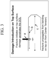
- damage introduction (a in Figure 3 ) occurs on the top surface of the glass-based material. Fracture initiates on the top surface of the glass-based material and damage either penetrates the glass-based material (b in Figure 3 ) or the fracture propagates from bending on the top surface or from the interior portions of the glass-based material (c in Figure 3 ).
- the IBoS test is designed to simultaneously introduce damage to the surface of the glass and apply bending under dynamic load. In some instances, the glass-based material exhibits improved drop performance when it includes a compressive stress than if the same glass-based material does not include a compressive stress.
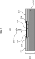
- Apparatus 200 includes a test stand 210 and a ball 230.
- Ball 230 is a rigid or solid ball such as, for example, a stainless steel ball, or the like. In one embodiment, ball 230 is a 4.2 gram stainless steel ball having diameter of 10 mm.
- the ball 230 is dropped directly onto the glass-based material sample 218 from a predetermined height h.
- Test stand 210 includes a solid base 212 comprising a hard, rigid material such as granite or the like.
- a sheet 214 having an abrasive material disposed on a surface is placed on the upper surface of the solid base 212 such that surface with the abrasive material faces upward.
- sheet 214 is sandpaper having a 30 grit surface and, in other embodiments, a 180 grit surface.
- the glass-based material sample 218 is held in place above sheet 214 by sample holder 215 such that an air gap 216 exists between glass-based material sample 218 and sheet 214.
- the air gap 216 between sheet 214 and glass-based material sample 218 allows the glass-based material sample 218 to bend upon impact by ball 230 and onto the abrasive surface of sheet 214.
- the glass-based material sample 218 is clamped across all corners to keep bending contained only to the point of ball impact and to ensure repeatability.
- sample holder 214 and test stand 210 are adapted to accommodate sample thicknesses of up to about 2 mm.
- the air gap 216 is in a range from about 50 ⁇ m to about 100 ⁇ m. Air gap 216 is adapted to adjust for difference of material stiffness (Young's modulus, Emod), but also includes the elastic modulus and thickness of the sample.
- An adhesive tape 220 may be used to cover the upper surface of the glass-based material sample to collect fragments in the event of fracture of the glass-based material sample 218 upon impact of ball 230.
- the abrasive surface is sandpaper, such as silicon carbide or alumina sandpaper, engineered sandpaper, or any abrasive material known to those skilled in the art for having comparable hardness and/or sharpness.
- sandpaper having 30 grit may be used, as it has a surface topography that is more consistent than either concrete or asphalt, and a particle size and sharpness that produces the desired level of specimen surface damage.
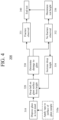
- a method 300 of conducting the IBoS test using the apparatus 200 described hereinabove is shown in Figure 4 .
- Step 310 a glass-based material sample (218 in Figure 2 ) is placed in the test stand 210, described previously and secured in sample holder 215 such that an air gap 216 is formed between the glass-based material sample 218 and sheet 214 with an abrasive surface.
- Method 300 presumes that the sheet 214 with an abrasive surface has already been placed in test stand 210. In some embodiments, however, the method may include placing sheet 214 in test stand 210 such that the surface with abrasive material faces upward.
- an adhesive tape 220 is applied to the upper surface of the glass-based material sample 218 prior to securing the glass-based material sample 218 in the sample holder 210.
- Step 320 a solid ball 230 of predetermined mass and size is dropped from a predetermined height h onto the upper surface of the glass-based material sample 218, such that the ball 230 impacts the upper surface (or adhesive tape 220 affixed to the upper surface) at approximately the center (i.e., within 1 mm, or within 3 mm, or within 5 mm, or within 10 mm of the center) of the upper surface.
- the extent of damage to the glass-based material sample 218 is determined (Step 330).
- the term "fracture” means that a crack propagates across the entire thickness and/or entire surface of a substrate when the substrate is dropped or impacted by an object.
- the sheet 218 with the abrasive surface may be replaced after each drop to avoid "aging" effects that have been observed in repeated use of other types (e.g., concrete or asphalt) of drop test surfaces.
- Various predetermined drop heights h and increments are typically used in method 300.
- the test may, for example, utilize a minimum drop height to start (e.g., about 10-20 cm). The height may then be increased for successive drops by either a set increment or variable increments.
- the test described in method 300 is stopped once the glass-based material sample 218 breaks or fractures (Step 331). Alternatively, if the drop height h reaches the maximum drop height (e.g., about 100 cm) without fracture, the drop test of method 300 may also be stopped, or Step 320 may be repeated at the maximum height until fracture occurs.
- IBoS test of method 300 is performed only once on each glass-based material sample 218 at each predetermined height h. In other embodiments, however, each sample may be subjected to multiple tests at each height.
- Step 340 If fracture of the glass-based material sample 218 has occurred (Step 331 in Figure 4 ), the IBoS test according to method 300 is ended (Step 340). If no fracture resulting from the ball drop at the predetermined drop height is observed (Step 332), the drop height is increased by a predetermined increment (Step 334) - such as, for example 5, 10, or 20 cm - and Steps 320 and 330 are repeated until either sample fracture is observed (331) or the maximum test height is reached (336) without sample fracture. When either Step 331 or 336 is reached, the test according to method 300 is ended.
- a predetermined increment such as, for example 5, 10, or 20 cm -
- embodiments of the glass-based material described herein have at least about a 60% survival rate when the ball is dropped onto the surface of the glass from a height of 80 cm.
- a glass-based material is described as having a 60% survival rate when dropped from a given height when three of five identical (or nearly identical) samples (i.e., having approximately the same composition and, when strengthened, approximately the same compressive stress and depth of compression or compressive stress layer, as described herein) survive the IBoS drop test without fracture when dropped from the prescribed height (here 80 cm).
- the survival rate in the 80 cm IBoS test of the glass-based materials that are strengthened is at least about 70%, in other embodiments, at least about 80%, and, in still other embodiments, at least about 90%.
- the survival rate of the strengthened glass-based materials dropped from a height of 100 cm in the IBoS test is at least about 60%, in other embodiments, at least about 70%, in still other embodiments, at least about 80%, and, in other embodiments, at least about 90%.
- At least five identical (or nearly identical) samples i.e., having approximately the same composition and, if strengthened, approximately the same compressive stress and depth of compression or layer
- larger numbers e.g., 10, 20, 30, etc.
- Each sample is dropped a single time from the predetermined height (e.g., 80 cm) or, alternatively, dropped from progressively higher heights without fracture until the predetermined height is reached, and visually (i.e., with the naked eye) examined for evidence of fracture (crack formation and propagation across the entire thickness and/or entire surface of a sample).
- a sample is deemed to have "survived” the drop test if no fracture is observed after being dropped from the predetermined height, and a sample is deemed to have "failed (or "not survived") if fracture is observed when the sample is dropped from a height that is less than or equal to the predetermined height.
- the survivability rate is determined to be the percentage of the sample population that survived the drop test. For example, if 7 samples out of a group of 10 did not fracture when dropped from the predetermined height, the survivability rate of the glass would be 70%.
- the glass-based materials described herein also demonstrate improved surface strength when subjected to ring-on-ring (ROR) testing and abraded ring-on-ring (AROR) testing.
- ROR test is identical to the AROR test, except the sample is not abraded prior to ring-on-ring testing.
- the strength of a material as measured by ROR testing and AROR testing is defined as the stress at which fracture occurs.
- the abraded ring-on-ring test is a surface strength measurement for testing flat glass specimens, and ASTM C1499-09(2013), entitled “Standard Test Method for Monotonic Equibiaxial Flexural Strength of Advanced Ceramics at Ambient Temperature," serves as the basis for the ring-on-ring abraded ROR test methodology described herein.
- the glass-based material sample is provided as a sheet and is abraded prior to ring-on-ring testing with 90 grit silicon carbide (SiC) particles that are delivered to the sample using the method and apparatus described in Annex A2, entitled “abrasion Procedures,” of ASTM C158-02(2012), entitled “Standard Test Methods for Strength of Glass by Flexure (Determination of Modulus of Rupture).
- SiC silicon carbide
- a surface of the glass-based material sample Prior to ring-on-ring testing a surface of the glass-based material sample is abraded as described in ASTM C158-02, Annex 2, to normalize and/or control the surface defect condition of the sample using the apparatus shown in Figure A2.1 of ASTM C158-02.
- the abrasive material is sandblasted onto the sample surface at a load of 103 kPa (15 psi) using an air pressure of 304 kPa (44 psi). After air flow is established, 5 cm 3 of abrasive material is dumped into a funnel and the sample is sandblasted for 5 seconds after introduction of the abrasive material.
- a glass-based material sample having at least one abraded surface is placed between two concentric rings of differing size to determine equibiaxial flexural strength (i.e., the maximum stress that a material is capable of sustaining when subjected to flexure between two concentric rings), as schematically shown in FIG. 5 .
- the abraded glass-based material sample 410 is supported by a support ring 420 having a diameter D 2 .
- a force F is applied by a load cell (not shown) to the surface of the glass-based material sample by a loading ring 430 having a diameter D 1 .
- the unabraded glass-based material sample 410 is supported in the same manner and force F is applied in the same manner.
- the ratio of diameters of the loading ring and support ring D 1 /D 2 may be in a range from about 0.2 to about 0.5. In some embodiments, D 1 /D 2 is about 0.5.
- Loading and support rings 430, 420 should be aligned concentrically to within 0.5% of support ring diameter D 2 .
- the load cell used for testing should be accurate to within ⁇ 1% at any load within a selected range. In some embodiments, testing is carried out at a temperature of 23 ⁇ 2°C and a relative humidity of 40 ⁇ 10%.
- Loading and support rings 430, 420 are typically made of hardened steel with hardness HR c > 40. ROR fixtures are commercially available.
- the intended failure mechanism for the ROR or AROR test is to observe fracture of the glass-based material sample 410 originating from the surface 430a within the loading ring 430. Failures that occur outside of this region - i.e., between the loading rings 430 and support rings 420 - are omitted from data analysis. In some instances, due to the thinness and strength of the glass-based material sample 410, however, large deflections that exceed 1 ⁇ 2 of the specimen thickness h are sometimes observed. It is therefore not uncommon to observe a high percentage of failures originating from underneath the loading ring 430. Stress cannot be accurately calculated without knowledge of stress development both inside and under the ring (collected via strain gauge analysis) and the origin of failure in each specimen. ROR and AROR testing therefore focuses on peak load at failure as the measured response.
- the strength of glass-based materials depends on the presence of surface flaws. However, the likelihood of a flaw of a given size being present cannot be precisely predicted, as the strength of glass-based materials is statistical in nature. A Weibull probability distribution is therefore generally used as a statistical representation of the data obtained.
- the glass-based material described herein when provided as a sheet, has a surface or equibiaxial flexural strength of about 250 MPa or greater or even 550 MPa or greater, as determined by AROR testing.
- the surface or equibiaxial flexural strength of the glass-based materials, as determined by AROR testing, and the survival rate of the glass-based materials dropped from various heights (e.g., 80 cm or 100 cm) in the IBoS test are with respect to a glass-based material having a sheet form and a thickness in the range from about 0.1 mm to about 2 mm.
- the shape and the dimensions (e.g., thickness) of the glass-based materials may vary.
- the glass-based material may be substantially planar or sheet-like.
- the glass-based material may also be curved or otherwise shaped or sculpted.
- the physical thickness of the glass-based material may vary along one or more of its dimensions for aesthetic and/or functional reasons. For example, the edges of the glass-based material may be thicker as compared to more central regions.
- the length, width and physical thickness dimensions of the glass-based material may also vary according to the application or use.
- the glass-based material may be a sheet having a thickness in the range from about 100 ⁇ m to about 2 mm.
- Exemplary thicknesses range from about 100 ⁇ m to about 1 mm (e.g., 100, 200, 300, 400, 500, 600, 700, 800, 900 or 1000 ⁇ m).
- the glass-based material may have a physical thickness greater than about 1 mm (e.g., about 2, 3, 4, or 5 mm).
- the glass-based material may be acid polished or otherwise treated to remove or reduce the effect of surface flaws.
- the glass-based material may be provided using a variety of different processes. For instance, various forming methods can include float glass or rolling processes and down-draw processes such as fusion draw and slot draw. In some embodiments, the glass-based materials may be described as down-drawable by processes known in the art, such as slot-drawing, fusion drawing, re-drawing, and the like, and have a liquidus viscosity of at least 13 kPa•s (130 kilopoise).
- the glass-based material may be strengthened by one or more processes.
- exemplary processes include chemically strengthening processes (e.g., ion-exchange process in which larger ions are exchanged for smaller ions in the surface of the material), thermal strengthening processes (e.g., thermal tempering) and the use of a mismatch of the coefficient of thermal expansion between the glass-based material and another material to create regions with compressive stress (CS) and regions with tensile stress or central tension (CT).
- the ions in the surface layer of the glass-based material are replaced by - or exchanged with - larger ions having the same valence or oxidation state.
- Ion exchange processes are typically carried out by immersing a glass-based material in one or more molten salt baths containing the larger ions to be exchanged with the smaller ions in the glass-based material.
- parameters for the ion exchange process including, but not limited to, bath composition and temperature, immersion time, the number of immersions of the glass-based material in a salt bath (or baths), use of multiple salt baths, additional steps such as annealing, washing, and the like, are generally determined by the composition of the glass-based material and the desired CS, depth of compressive stress layer (DOL) or depth of compression (DOC).
- ion exchange of glass-based materials may be achieved by immersion in at least one molten bath containing a salt such as, but not limited to, nitrates, sulfates, and chlorides of the larger alkali metal ion.
- the bath(s) may include molten alkali salts, such as lithium salt, sodium salt, and/or potassium salt.
- the bath(s) may include LiNO 3 , LiCl, Li 2 SO 4 , KNO 3 , KCl, K 2 SO 4 , NaNaO, NaSO 4 , CaNitrate, KNO 3 and other similar compositions or combinations thereof in molten form.
- the molten salt bath includes a mixture of 90 % (by weight) Li 2 SO 4 -10% K 2 SO 4 .
- the temperature of the molten salt bath typically is in a range from300 up about 900°C while immersion times range from about 15 minutes up to about 40 hours.
- the temperature depends on the salt bath composition. It should be noted that such temperatures may reach about 700 °C and, due to the corrosion at such high temperatures, the molten salt baths may be contained in platinum vessels.
- the bath composition, bath temperature and immersion times may differ from those described above.
- the glass-based material may be subjected to ion exchange with silver, copper, other elements, to impart other properties or to lower the melting temperature of salt bath mixture.
- the degree of chemical strengthening achieved by ion exchange may be quantified based on the parameters of CT, surface CS, and DOL or DOC.
- Compressive stress and depth of layer are measured using those means known in the art. Such means include, but are not limited to, measurement of surface stress (FSM) using refractive near-field (RNF) measurements as described in U.S. Patent No. 8,854,623B2 , entitled "Systems and methods for measuring a profile characteristic of a glass sample”.
- FSM surface stress
- RMF refractive near-field
- CT and CS are expressed herein in megaPascals (MPa)
- physical thickness t is expressed in either micrometers ( ⁇ m) or millimeters (mm)
- DOL or DOC is expressed in micrometers ( ⁇ m).
- the glass-based material can have a surface CS of 250 MPa or greater, 300 MPa or greater, e.g., 400 MPa or greater, 450 MPa or greater, 500 MPa or greater, 550 MPa or greater, 600 MPa or greater, 650 MPa or greater, 700 MPa or greater, 750 MPa or greater or 800 MPa or greater.
- the strengthened glass-based material may have a DOL of 40 ⁇ m or greater (e.g., 45 ⁇ m, 50 ⁇ m, 60 ⁇ m, 70 ⁇ m, 80 ⁇ m, 90 ⁇ m, 100 ⁇ m, 110 ⁇ m, 120 ⁇ m, 130 ⁇ m or 140 ⁇ m or greater) and/or a CT of 50 MPa or less, 40 MPa or greater, 20 MPa or greater, or 10 MPa or greater.
- the glass-based materials described herein exhibit the same CS levels as other materials (e.g., glass) and higher CT levels that such materials, without being frangible.
- the glass-based materials described herein may be used in various applications.
- the glass-based materials may be used in various glass articles such as cover plates, enclosures or housings for consumer electronic products to protect critical devices within the product, to provide a user interface for input and/or display, and/or many other functions.
- consumer electronic products include mobile devices, such as smart phones, mp3 players and computer tablets.
- the terms "enclosure,” “cover plate,” and “window” are used interchangeably and refer to articles, including windows, cover plates, screens, panels, and substrates, that form the outer portion of a display screen, window, or structure for mobile electronic devices.
- the glass-based materials may be used in architectural articles, transportation-related articles, appliance articles, or any article that requires transparency, scratch-resistance, fracture toughness or a combination thereof.
- Compositions 1-5 as set forth in Table 1, were batched and melted by placing 1000 grams of raw materials in a platinum crucible, and placing the crucible in a furnace preheated at 1500°C. The temperature in the furnace is increased to 1600 °C in 1 hour after the raw materials are introduced and the raw materials are heated at 1600 °C for 4 more hours. The melted glass is poured and rolled to a thickness of 6 mm and annealed at 650 °C.
- the resulting glasses from Compositions 1-5 are then cerammed according to either Ceramming Schedule A or Ceramming Schedule B to provide Glass-based Materials 1-5, respectively, as shown in Table 2.
- Ceramming Schedule A includes heat treating the glass at a temperature of 750 °C ("nucleation temperature” or T N ) for 4 hours to nucleate the glass, followed by heat treating the glass at a temperature of 775 °C ("ceramming temperature" or Tc) for 2 hours to form a second phase.
- Ceramming Schedule B includes heat treating the glass at a temperature of 750 °C (T N ) for 4 hours to nucleate the glass, followed by heat treating the glass at a temperature of 830 °C (T C ) for 2 hours to form a second phase.
- the heating rate between the nucleation temperature and the ceramming temperature was 10°C/minute.
- the properties of the resulting Glass-based Materials 1-5 are shown in Table 2 after being cerammed according to Ceramming Schedule A or Ceramming Schedule B.
- the CTE values reported in Table 2 were measured over a temperature range from about 25 °C to about 700 °C.
- the fracture toughness values (K 1C ) are measured by Vickers indentation.
- the resulting Glass-based Materials 1-5 were also examined using X-ray diffraction analysis and showed the presence of a second phase including crystals having a mullite structure.
- the mean size of the crystals, as determined by Rietveld analysis, is also included in Table 2.
- the Glass-based Materials 1-5 exhibited high transmittance (i.e., greater than about 90%/mm) and a high fracture toughness (i.e., greater than about 1.3 MPa.m 1/2 ).
- Figure 6 shows an image of Glass-based Material 1, formed using Ceramming Schedule B, taken by SEM. The mullite crystals observed had an elongated form. Without being bound by theory, it is believed that the crystal shape may contribute to the observed increased fracture toughness.
- Table 1 Compositions 1-5.
- Composition 1 Composition 2 Composition 3 Composition 4 Composition 5 Mol% Wt% Mol% Wt% Mol% Wt% Mol% Wt% Mol% Wt% SiO 2 59.85 53 59.85 50.92 59.85 53.55 59.85 51.21 61.35 54.37 Al 2 O 3 16.64 25 16.64 24.03 16.64 25.26 16.64 24.16 18.14 27.28 B 2 O 3 14.62 15 14.62 14.41 14.62 15.16 14.62 14.49 11.62 11.93 Na 2 O 2.16 1.99 2.16 1.91 2.16 1.97 K 2 O 2.16 3 2.16 2.88 MgO 6.73 4 6.73 4.04 6.73 4 ZnO 6.73 7.75 6.73 7.8 SnO 2 0.2 0.43 0.2 0.44 Table 2: Measured properties of Glass-based Materials 1-5.
- Composition 6 as set forth in Table 3 was prepared by mixing dry batch materials thoroughly and placing the batch materials in a platinum crucible. The platinum crucible was placed in a globar furnace for 6 hours at 1615 °C. Patties of the melted glass were rolled to a thickness of 6 mm and annealed at 675°C for 1 hour. The resulting glass was then cerammed according to Ceramming Schedule C in a resistance-heated furnace to form a second phase. Ceramming Schedule C included heat treating the glass at temperature of 820°C (T N ) for 4 hours to nucleate the glass, followed by heat treating the glass at a temperature of 875°C (T C ) for 4 hours.
- the resulting Glass-based Material 6 was transparent over the visible spectrum and highly crystalline (with less than 5 w% of the Glass-based Material 6 comprising residual glass).
- Glass-based Material 6 can be characterized as including a second phase with a large proportion of fine-grained stuffed ⁇ -quartz solid solution crystals.
- the second phase was obtained by controlled crystallization of a MgO-Li 2 O-Al 2 O 3 -SiO 2 glass containing appropriate amounts of nucleating agents such as TiO 2 and/or ZrO 2 .
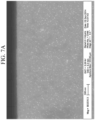
- Figure 7A shows an image of Glass-based Material 6 taken by SEM. As shown in Figure 7A , Glass-based Material 6 is highly crystalline and included stuffed ⁇ -quartz solid solution crystals having a dimension of 100 nm to about 150 nm.
- Glass-based Material 6 was then chemically strengthened using molten salt bath including reagent grade of alkali metal salt included a mixture of 90 % (by weight) Li 2 SO 4 -10% K 2 SO 4 .
- molten salt bath including reagent grade of alkali metal salt included a mixture of 90 % (by weight) Li 2 SO 4 -10% K 2 SO 4 .
- reagent grade of alkali metal salt included a mixture of 90 % (by weight) Li 2 SO 4 -10% K 2 SO 4 .
- FIG. 7B shows the Glass-based Material 6 after ion exchange and being etched by hydrofluoric acid. As shown in Figure 7B , the ion exchange process modifies the composition of the residual glass at the surface.
- the properties of the resulting Glass-based Material 6 are shown in Table 4.
- the CTE value reported in Table 4 was measured over a temperature range from about 25 °C to about 700 °C.
- the fracture toughness value (Kic) was measured by Vickers indentation.
- Glass-based Material 6 was also examined using X-ray diffraction analysis, which showed the presence of a second phase including ⁇ -quartz crystals.
- the mean size of the crystals, as determined by Rietveld analysis, is also included in Table 4.
- the transmittance value provided is with respect to the visible wavelength range from about 400 nm to about 800 nm. Table 4: Measured properties of Glass-based Material 6.
- Samples 6A-6D each had a thickness of 2.1 mm and were tested for ROR and AROR (using 90 grit silicon carbide (SiC) particles that are delivered at 103 kPa (15 psi) for 5 seconds).
- the DOL values of Samples 6A-6D were also measured.
- the ROR strength, AROR strength and DOL data of strengthened Samples 6A-6D are shown in Figure 8 .
- Sample 6B exhibited a favorable combination of strength and DOL (> 100 ⁇ m).
- the measured mechanical properties of Sample 6A are shown in Table 6.
- the compressive stress was measured by RNF.
- the hardness of Sample 6A was measured using a Knoop indenter at a 100g load.
- Table 6 Measured mechanical properties of Sample 6A. Before Strengthening After Strengthening CS (RNF) (MPa) NA 600 DOL ( ⁇ m) NA 40 AROR (MPa) 412 Vickers IFT (kgf) 0.3 5-6 HK100 (MPa) 652 MPa 636 Young's modulus (GPa) 96.6 GPa 98 K 1C (MPa.m 1/2 ) 0.94 NA
- Sample 6E of Glass-based Material 6 was immersed in the same molten bath as Sample 6D but having a temperature of 750 °C, for 4 hours.
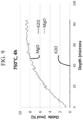
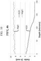
- Figures 9-10 show EDX scan of the compressive stress layer of Samples 6E and 6D, respectively.
- a "low bath temperature" i.e., 750°C, Sample 6E
- MgO diffuses out of the Glass-based Material
- lithium from the molten salt bath diffused into the Glass-based Material
- potassium from the molten salt bath does not diffuse at all.
- KST Knoop scratch threshold
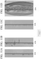
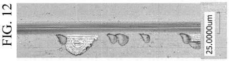
- Figure 12 shows an image of Glass-based Material 1 after being scratched using a load of 5 N.
- the scratch has a width w of about 13 micrometers and chips having a size of up to 25 micrometers. Accordingly, Glass-based Material 1 shows the size of the chips is less than about 2w. Accordingly, Glass-based material 1 is free of chips having a size greater than 2w.
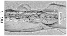
- Figure 13 shows an image of Glass-based Material 6B after being scratched using a load of 5 N. As shown in Table 7, the scratch width including chips is 75.5 micrometers, and Figure 13 shows the scratch width w (without chips) is about 25 micrometers. Accordingly, Glass-based Material 6B shows the size of the chips is about 3w. Accordingly, Glass-based material 6B is free of chips having a size greater than 3w.
- Compositions 7-12 as set forth in Table 8 were prepared by mixing dry batch materials thoroughly and placing the batch materials in a platinum crucible. The platinum crucible was placed in a globar furnace for 6 hours at 1615 °C. Patties of the melted glass were rolled to a thickness of 6 mm and annealed at 675°C for 1 hour. The resulting glass was then cerammed in a resistance-heated furnace to form a second phase.
- Table 8 Compositions 7-12 and DOL for Glass-based Materials 7-12.
- the resulting Glass-based Materials 7-12 were then chemically strengthened using molten salt bath including reagent grade of alkali metal salt included a mixture of 90 % (by weight) Li 2 SO 4 -10% K 2 SO 4 and a temperature of 725 °C.
- the Glass-based Materials were immersed in the molten salt bath for 4 hours.
- the resulting depths of compressive stress layer (DOL) are shown in Table 8.
- Comparative Glass Material 13 a known glass substrate (Comparative Glass Material 13) (having no second phase) having a nominal composition of 58 mol% SiO 2 , 16.5 mol% Al 2 O 3 , 16.7 mol% Na 2 O, 2.8 mol% MgO, 6.5 mol% P 2 O 5 and 0.05 mol% SnO 2 , and thickness of 0.8 mm.
- Ten samples of Comparative Glass Material 13 were chemically strengthened to exhibit a compressive stress of 865 MPa and DOL of 97 micrometers. As shown in Figure 14 , none of the samples of Comparative Glass Material 13 survived beyond a drop height of 150 cm.
Description
- The disclosure relates to transparent glass-based materials exhibiting improved fracture toughness and scratch resistance.
- Known glass-based materials exhibiting improved flexural strength often rely on post-processing such as chemical strengthening and thermal strengthening. Such chemically strengthened glasses have been widely used in electronic devices including hand-held displays and tablets. Other strength performance (e.g., modulus of rupture and fracture toughness) and scratch resistance of these glass-based materials may be limited. Known glass-based materials that exhibit improved modulus of rupture or fracture toughness and scratch resistance are generally opaque. Accordingly, there is a need for a transparent material that exhibits improved fracture toughness and scratch resistance over known glass-based materials.
- The document
US 2014/0134397 A1 describes glass-ceramics showing high transmittance in the visible spectral range and high fracture toughness. - The present invention relates to a glass-based material comprising a glass phase and a second phase that is different from and is dispersed in the glass phase are provided. The second phase may comprise a crystalline or a nanocrystalline phase, a fiber, and/or glass particles. In some embodiments, the second phase is crystalline. The glass-based material has a high modulus and fracture toughness and is scratch resistant. In some embodiments, the material can be chemically strengthened. For example, such materials may be ion exchangeable.
- Specifically, the invention relates to a glass-based material comprising a glass phase and a second phase that is different than the glass phase and dispersed within the glass phase. The glass-based material has a transmittance of at least about 88%/mm over a visible spectrum ranging from about 400 nm to about 700 nm and a fracture toughness of at least about 0.9 MPa·m1/2. When scratched with a Knoop diamond at a load of at least 5 N to form a scratch having a width w, a surface of the glass-based material is free of chips having a size of greater than 3w.
- The invention further relates to a glass-based material comprising a glass phase and a second phase that is different than the glass phase and dispersed within the glass phase. The glass-based material has a transmittance of at least 88%/mm over a visible spectrum ranging from about 400 nm to about 700 nm and a fracture toughness (Kic) of at least about 0.9 MPa·m1/2. The glass phase has a first index of refraction and the second phase has a second index of refraction, and the difference between the first index of refraction and the second index of refraction is less than about 0.025. The second phase of the glass-based material comprises a crystalline phase including crystals having a mean crystalline size in a range from 5 nm to 200 nm, and the volume fraction of the second phase in the glass-based material is in a range from 10% to about 98% .
- These and other aspects, advantages, and salient features will become apparent from the following detailed description, the accompanying drawings, and the appended claims.
-
-
FIGURE 1 is a schematic cross-sectional view of prior art apparatus that is used to perform ball drop testing; -
FIGURE 2 is a schematic cross-sectional view of an embodiment of the apparatus that is used to perform the inverted ball on sandpaper (IBoS) test; -
FIGURE 3 is a schematic cross-sectional representation of the dominant mechanism for failure due to damage introduction plus bending that typically occurs in glass-based materials that are used in mobile or hand held electronic devices; -
FIGURE 4 is a flow chart for a method of conducting the IBoS test in the apparatus described herein; -
FIGURE 5 is a schematic cross-sectional view of a ring-on-ring apparatus; -
FIGURE 6 shows a scanning electron microscope image of glass-based material 1; -
FIGURE 7A shows a scanning electron microscope image of glass-basedmaterial 6, before being subjected to ion exchange; -
FIGURE 7B shows a scanning electron microscope image of glass-basedmaterial 6, after being subjected to ion exchange; -
FIGURE 8 is a graph showing the ROR strength, AROR strength and compressive stress layer depth data of strengthenedSamples 6A-6D; -
FIGURE 9 shows an energy-dispersive X-ray (EDX) spectrum of Glass-basedMaterial 6 after being chemically strengthened for 4 hours in a bath having a temperature of 750 °C; -
FIGURE 10 shows an energy-dispersive X-ray (EDX) spectrum of Glass-basedMaterial 6 after being chemically strengthened for 4 hours in a bath having a temperature of 775 °C; -
FIGURES 11A-11D are images Glass-based Material 1 after being scratched with a Knoop diamond at different loads; -
FIGURE 12 is an enlarged image of Glass-based Material 1 after being scratched with a Knoop diamond at a load of 5 N; -
FIGURE 13 is an enlarged image of Glass-basedMaterial 6B after being scratched with a Knoop diamond at a load of 5 N; and -
Figure 14 is a graph showing IBoS results for Glass-basedMaterial 7 andComparative Glass Material 13. - In the following description, like reference characters designate like or corresponding parts throughout the several views shown in the figures. It is also understood that, unless otherwise specified, terms such as "top," "bottom," "outward," "inward," and the like are words of convenience and are not to be construed as limiting terms. In addition, whenever a group is described as comprising at least one of a group of elements and combinations thereof, it is understood that the group may comprise, consist essentially of, or consist of any number of those elements recited, either individually or in combination with each other. Similarly, whenever a group is described as consisting of at least one of a group of elements or combinations thereof, it is understood that the group may consist of any number of those elements recited, either individually or in combination with each other. Unless otherwise specified, a range of values, when recited, includes both the upper and lower limits of the range as well as any ranges therebetween. As used herein, the indefinite articles "a," "an," and the corresponding definite article "the" mean "at least one" or "one or more," unless otherwise specified. It also is understood that the various features disclosed in the specification and the drawings can be used in any and all combinations.
- Referring to the drawings in general, it will be understood that the illustrations are for the purpose of describing particular embodiments and are not intended to limit the disclosure or appended claims thereto. The drawings are not necessarily to scale, and certain features and certain views of the drawings may be shown exaggerated in scale or in schematic in the interest of clarity and conciseness.
- As used herein, the terms "glass article" and "glass articles" are used in their broadest sense to include any object made wholly or partly of glass or the glass-based materials described herein. Unless otherwise specified, all compositions are expressed in terms of mole percent (mol%). Coefficients of thermal expansion (CTE) are expressed in terms of 10-7/°C and represent a value measured over a temperature range from about 20°C to about 300°C, unless otherwise specified.
- As used herein, the term "liquidus temperature," or "TL" refers to the temperature at which crystals first appear as a molten glass cools down from the melting temperature, or the temperature at which the very last crystals melt away as temperature is increased from room temperature. As used herein, the term "165 kP temperature" or "T165kP" refers to the temperature at which the glass or glass melt has a viscosity of 16,000 Pa•s (160,000 Poise (P), or 160 kiloPoise (kP)). As used herein, the term "35 kP temperature" or "T35kp" refers to the temperature at which the glass or glass melt has a viscosity of 3,500 Pa•s (35,000 Poise (P), or 35 kiloPoise (kP)).
- It is noted that the terms "substantially" and "about" may be utilized herein to represent the inherent degree of uncertainty that may be attributed to any quantitative comparison, value, measurement, or other representation. These terms are also utilized herein to represent the degree by which a quantitative representation may vary from a stated reference without resulting in a change in the basic function of the subject matter at issue. Thus, a glass that is "substantially free of MgO" is one in which MgO is not actively added or batched into the glass, but may be present in very small amounts as a contaminant.
- Vickers crack initiation thresholds or indentation fracture threshold (IFT) described herein are determined by applying and then removing indentation load to a substrate. The IFT test is performed using an Automated Hardness Testers Tukon™ 2500 provided by Wilson® Hardness. A maximum indentation load is applied and held on the substrate for 10 seconds. The indentation cracking threshold is defined at the indentation load in units of kgf of 10 indents that exhibit a radial and/or median cracks emanating from the corners of the indent impression. The maximum load is increased until the threshold is met for a given substrate. All indentation measurements are performed at room temperature and humidity.
- The invention relates to a glass-based material including a glass and a second phase that is different than the glass phase. The second phase is dispersed within the glass phase.
- The glass phase of the glass-based material may include at least one of a soda lime glass, an alkali aluminosilicate glass, borosilicate glass, aborosilicate glass, and a lithium alumina silicate glass. In some embodiments, the glass phase may be substantially free of arsenic or antimony oxides. Exemplary glass phase compositions include SiO2 in the range from about 55 mol% to about 75 mol%, Al2O3 in the range from about 10 mol% to about 20 mol%, B2O3 in the range from about 0 mol% to about 16 mol%, Na2O in a range from about 0 mol% to about 4 mol%, K2O in a range from about 0 mol% to about 4 mol%, Li2O in a range from about 0 mol% to about 8 mol%, MgO in a range from about 0 mol% to about 12 mol%, ZnO in a range from about 0 mol% to about 10 mol%, ZrO2 in a range from about 0 mol% to about 5 mol%, and SnO2 in a range from about 0 mol% to about 0.5 mol%.
- One or more specific embodiments may include a glass phase having a composition including SiO2 in the range from about 55 mol% to about 75 mol%, Al2O3 in the range from about 12 mol% to about 20 mol%, B2O3 in the range from about 10 mol% to about 16 mol%, Na2O in a range from about 0 mol% to about 4 mol%, K2O in a range from about 0 mol% to about 4 mol%, MgO in a range from about 4 mol% to about 12 mol%, ZnO in a range from about 4 mol% to about 10 mol%, and SnO2 in a range from about 0 mol% to about 0.5 mol%. In some embodiments, the glass phase may include any one or more of Li2O in the range from about 0 mol% to about 4 mol%, SrO in the range from about 0 mol% to about 4 mol%, and CaO of about 0 mol% to about 4 mol%.
- More specific glass phase compositions include SiO2 in the range from about 55 mol% to about 75 mol%, Al2O3 in the range from about 10 mol% to about 16 mol%, B2O3 in the range from about 0 mol% to about 8 mol% (or from about 0 mol% to about 5 mol%), Na2O in a range from about 0 mol% to about 4 mol%, Li2O in a range from about 4 mol% to about 8 mol%, MgO in a range from about 2 mol% to about 12 mol%, ZnO in a range from about 0 mol% to about 4 mol%, ZrO2 in a range from about 1 mol% to about 5 mol%, and SnO2 in a range from about 0 mol% to about 0.5 mol%.
- Some embodiments of glass-based material that includes a β-quartz second phase include SiO2 in the range from about 55 mol% to about 75 mol%, Al2O3 in the range from about 10 mol% to about 16 mol%, Na2O in a range from about 0 mol% (or 0.2 mol%) to about 4 mol%, Li2O in a range from about 1.5 mol% to about 8 mol%, MgO in a range from about 6 mol% to about 12 mol%, ZrO2 in a range from about 1 mol% to about 5 mol%, and SnO2 in a range from about 0 mol% to about 0.5 mol%.
- The second phase may be present in embodiments of the glass-based material as nanocrystals, fibers, particles or combinations thereof. Where the second phase includes nanocrystals, such nanocrystals may include at least one of diamond, carbon, and a metal. Where the second phase includes fibers, such fibers may include at least one of carbon, a ceramic, and a glass. In one or more embodiments, where the second phase is provided as particles, such particles may be amorphous (e.g., glass) or crystalline.
- In one or more embodiments, the second phase may include a crystalline phase. In some embodiments, the crystalline phase may include crystals having a mean crystalline size in a range from 5 nm to 200 nm, as determined from x-ray diffraction/Rietveld analysis.
- In one or more embodiments, the crystalline phase may include up to 98 volume % of the glass-based materials. In some embodiments, the crystalline phase may include from about 10 volume % to about 98 volume%, from about 15 volume % to about 98 volume %, from about 20 volume % to about 98 volume %, from about 30 volume % to about 98 volume %, from about 40 volume % to about 98 volume %, from about 50 volume % to about 98 volume %, from about 60 volume % to about 98 volume %, from about 10 volume % to about 95 volume %, from about 10 volume % to about 90 volume %, or from about 10 volume % to about 80 volume %.
- The crystalline phase may include any one or more of mullite, spinel, α-quartz, β-quartz solid solution, petalite, lithium dissilicate, β-spodumene, nepheline, and alumina. In some embodiments, glass-based material includes a second crystalline phase. The second crystalline phase may include the crystalline phases described herein, and some embodiments may include either one or both nepheline and anorthite.
- In one or more embodiments, the glass phase and the second phase have a minimal difference in refractive index. For example, the difference in refractive index between the glass phase and the second phase may be less than about 0.025 (e.g., about 0.02 or less, about 0.015 or less, about 0.01 or less or about 0.005 or less). In some instances, the refractive index difference between the glass phase and the second phase may be greater than the values provided herein, if the crystallites are of sufficient size to provide transparency (i.e., the crystallites are sufficiently small in dimension) For example, the refractive index difference may be difference may be greater than 0.025 (e.g., up to about 0.5) if the crystallites have a major dimension of less than about 100 nm or less than about 50 nm.
- The glass-based material exhibits a transmittance of at least about 88%/mm over a visible spectrum ranging from about 400 nm to about 700 nm. In some embodiments, the glass-based materials exhibit a transmittance of about 90% or greater, about 92% or greater or about 94% or greater, over the visible spectrum in the range from about 400 nm to about 700 nm.
- The glass-based material further exhibits a fracture toughness of about 0.9 MPa·m1/2 or greater, for example of about 1.2 MPa·m1/2 or greater (e.g., about 1.3 MPa·m1/2 or greater, 1.4 MPa·m1/2 or greater, 1.5 MPa·m1/2 or greater, 1.6 MPa·m1/2 or greater, or 17 MPa·m1/2 or greater). The fracture toughness may be measured using either Vickers indentation or Chevron notch indentation techniques commonly used in the art.
- In one or more embodiments, the glass-based material is resistant to sharp impact and is be able to withstand direct or point impacts. Such glass-based materials do not exhibit lateral damage such as, but not limited to, chipping when scratched at a rate of 0.4 mm/s with a Knoop diamond that is oriented so that the angle between the leading and trailing edges of the tip of the Knoop diamond is 172°30' at a load of 5 N and, in some embodiments, at a load of 10 N. As used herein, "chipping" refers to the removal or ejection of glass fragments from a surface of a glass when the surface is scratched with an object such as a stylus. As used herein, "chip" can refer to either a fragment removed during scratching of the glass-based material surface or the region on the surface from which the chip is removed. In the latter sense, a chip is typically characterized as a depression in the vicinity of the scratch. When scratched, the glass-based material described herein does not exhibit chipping (i.e., chips are not generated, or the glass is free of chips) beyond a region extending laterally on either side of the scratch track (i.e., the scratch formed by the Knoop diamond) formed for a distance d that is greater than twice the width w of the scratch and, in another embodiment, three times the width w of the scratch. In other words, chipping generated by scratching is limited to a region bordering either side of the scratch track, wherein the width of the region is no greater than twice (in some embodiment, no greater than three times) the width w of the scratch. In other words, when a surface of the glass-based material is scratched with a Knoop diamond at a load of at least 5 N to form a scratch having a width w, the resulting scratch is free of chips having a size of greater than 3w or 2w.
- The glass-based material may exhibit a relatively low coefficient of thermal expansion. For example, in one or more embodiments, the glass-based material has a coefficient of thermal expansion of less than about 45 × 10-7 K-1. In some instances, the coefficient of thermal expansion may be about 40 × 10-7 K-1 or less, about 35 × 10-7 K-1 or less, or about 30 × 10-7 K-1 or less. The lower limit of the coefficient of thermal expansion may be about 15 × 10-7 K-1.
- The glass-based material may exhibit increased Young's modulus (E), when compared to known glass materials exhibiting the same or comparable transmittance. For example, in one or more embodiments, the glass-based material may exhibit a Young's modulus (E) of greater than about 70 MPa or greater than about 75 MPa. In some instances, the Young's modulus (E) may be in the range from about 80 GPa to about 100 GPa (e.g., from about 80 MPa to about 95 MPa, from about 80 MPa to about 90 MPa, from about 85 MPa to about 100 MPa, or from about 90 MPa to about 100 MPa).
- The glass-based materials described herein demonstrate improved fracture resistance when subjected to repeated drop tests. It should be noted that the glass-based materials are provided as sheets for such testing. The purpose of such drop tests is to characterize the performance of such glass-based materials in normal use as display windows or cover plates for handheld electronic devices such as cell phones, smart phones, and the like.
- A typical ball drop test concept that is currently in use is shown in
Figure 1 . The balldrop test assembly 150 includes a solid,hard substrate 112 such as a granite slab or the like and asteel ball 130 of predetermined mass and diameter. A sample 120 (e.g., a sheet of a material) is secured to thesubstrate 112, and a piece ofsandpaper 114 having the desired grit is placed on the upper surface of thesample 120 opposite thesubstrate 112. Thesandpaper 114 is placed on thesample 120 such that the roughenedsurface 114a of the sandpaper contacts theupper surface 122 of thesample 120. Thesteel ball 130 is allowed to fall freely from a predetermined height h onto thesandpaper 114. Theupper surface 122 or compression face of thesample 220 makes contact with the roughenedsurface 114a of thesandpaper 114, introducing cracks into the surface of the upper surface/compression face 122. The height h may be increased incrementally until either a maximum height is reached or the glass sample fractures. - When used with glass-based samples, the
ball drop test 150 described hereinabove does not represent the true behavior of glass-based materials when dropped onto and contacted by a rough surface. Instead, it is known that the face of the glass-based material bends outward in tension, rather than inward in compression as shown inFigure 1 . - An inverted ball on sandpaper (IBoS) test is a dynamic component level test that mimics the dominant mechanism for failure due to damage introduction plus bending that typically occurs in glass-based materials that are used in mobile or hand held electronic devices, as schematically shown in
Figure 2 . In the field, damage introduction (a inFigure 3 ) occurs on the top surface of the glass-based material. Fracture initiates on the top surface of the glass-based material and damage either penetrates the glass-based material (b inFigure 3 ) or the fracture propagates from bending on the top surface or from the interior portions of the glass-based material (c inFigure 3 ). The IBoS test is designed to simultaneously introduce damage to the surface of the glass and apply bending under dynamic load. In some instances, the glass-based material exhibits improved drop performance when it includes a compressive stress than if the same glass-based material does not include a compressive stress. - An IBoS test apparatus is schematically shown in
Figure 2 .Apparatus 200 includes atest stand 210 and aball 230.Ball 230 is a rigid or solid ball such as, for example, a stainless steel ball, or the like. In one embodiment,ball 230 is a 4.2 gram stainless steel ball having diameter of 10 mm. Theball 230 is dropped directly onto the glass-basedmaterial sample 218 from a predetermined height h. Test stand 210 includes asolid base 212 comprising a hard, rigid material such as granite or the like. Asheet 214 having an abrasive material disposed on a surface is placed on the upper surface of thesolid base 212 such that surface with the abrasive material faces upward. In some embodiments,sheet 214 is sandpaper having a 30 grit surface and, in other embodiments, a 180 grit surface. The glass-basedmaterial sample 218 is held in place abovesheet 214 bysample holder 215 such that anair gap 216 exists between glass-basedmaterial sample 218 andsheet 214. Theair gap 216 betweensheet 214 and glass-basedmaterial sample 218 allows the glass-basedmaterial sample 218 to bend upon impact byball 230 and onto the abrasive surface ofsheet 214. In one embodiment, the glass-basedmaterial sample 218 is clamped across all corners to keep bending contained only to the point of ball impact and to ensure repeatability. In some embodiments,sample holder 214 and test stand 210 are adapted to accommodate sample thicknesses of up to about 2 mm. Theair gap 216 is in a range from about 50 µm to about 100 µm.Air gap 216 is adapted to adjust for difference of material stiffness (Young's modulus, Emod), but also includes the elastic modulus and thickness of the sample. Anadhesive tape 220 may be used to cover the upper surface of the glass-based material sample to collect fragments in the event of fracture of the glass-basedmaterial sample 218 upon impact ofball 230. - Various materials may be used as the abrasive surface. In a one particular embodiment, the abrasive surface is sandpaper, such as silicon carbide or alumina sandpaper, engineered sandpaper, or any abrasive material known to those skilled in the art for having comparable hardness and/or sharpness. In some embodiments, sandpaper having 30 grit may be used, as it has a surface topography that is more consistent than either concrete or asphalt, and a particle size and sharpness that produces the desired level of specimen surface damage.
- In one aspect, a
method 300 of conducting the IBoS test using theapparatus 200 described hereinabove is shown inFigure 4 . InStep 310, a glass-based material sample (218 inFigure 2 ) is placed in thetest stand 210, described previously and secured insample holder 215 such that anair gap 216 is formed between the glass-basedmaterial sample 218 andsheet 214 with an abrasive surface.Method 300 presumes that thesheet 214 with an abrasive surface has already been placed intest stand 210. In some embodiments, however, the method may include placingsheet 214 in test stand 210 such that the surface with abrasive material faces upward. In some embodiments (Step 310a), anadhesive tape 220 is applied to the upper surface of the glass-basedmaterial sample 218 prior to securing the glass-basedmaterial sample 218 in thesample holder 210. - In
Step 320, asolid ball 230 of predetermined mass and size is dropped from a predetermined height h onto the upper surface of the glass-basedmaterial sample 218, such that theball 230 impacts the upper surface (oradhesive tape 220 affixed to the upper surface) at approximately the center (i.e., within 1 mm, or within 3 mm, or within 5 mm, or within 10 mm of the center) of the upper surface. Following impact inStep 320, the extent of damage to the glass-basedmaterial sample 218 is determined (Step 330). As previously described hereinabove, herein, the term "fracture" means that a crack propagates across the entire thickness and/or entire surface of a substrate when the substrate is dropped or impacted by an object. - In
method 300, thesheet 218 with the abrasive surface may be replaced after each drop to avoid "aging" effects that have been observed in repeated use of other types (e.g., concrete or asphalt) of drop test surfaces. - Various predetermined drop heights h and increments are typically used in
method 300. The test may, for example, utilize a minimum drop height to start (e.g., about 10-20 cm). The height may then be increased for successive drops by either a set increment or variable increments. The test described inmethod 300 is stopped once the glass-basedmaterial sample 218 breaks or fractures (Step 331). Alternatively, if the drop height h reaches the maximum drop height (e.g., about 100 cm) without fracture, the drop test ofmethod 300 may also be stopped, orStep 320 may be repeated at the maximum height until fracture occurs. - In some instances, IBoS test of
method 300 is performed only once on each glass-basedmaterial sample 218 at each predetermined height h. In other embodiments, however, each sample may be subjected to multiple tests at each height. - If fracture of the glass-based
material sample 218 has occurred (Step 331 inFigure 4 ), the IBoS test according tomethod 300 is ended (Step 340). If no fracture resulting from the ball drop at the predetermined drop height is observed (Step 332), the drop height is increased by a predetermined increment (Step 334) - such as, for example 5, 10, or 20 cm - andSteps Step method 300 is ended. - When subjected to the inverted ball on sandpaper (IBoS) test described above, embodiments of the glass-based material described herein have at least about a 60% survival rate when the ball is dropped onto the surface of the glass from a height of 80 cm. For example, a glass-based material is described as having a 60% survival rate when dropped from a given height when three of five identical (or nearly identical) samples (i.e., having approximately the same composition and, when strengthened, approximately the same compressive stress and depth of compression or compressive stress layer, as described herein) survive the IBoS drop test without fracture when dropped from the prescribed height (here 80 cm). In other embodiments, the survival rate in the 80 cm IBoS test of the glass-based materials that are strengthened is at least about 70%, in other embodiments, at least about 80%, and, in still other embodiments, at least about 90%. In other embodiments, the survival rate of the strengthened glass-based materials dropped from a height of 100 cm in the IBoS test is at least about 60%, in other embodiments, at least about 70%, in still other embodiments, at least about 80%, and, in other embodiments, at least about 90%.
- To determine the survivability rate of the glass-based materials when dropped from a predetermined height using the IBoS test method and apparatus described hereinabove, at least five identical (or nearly identical) samples (i.e., having approximately the same composition and, if strengthened, approximately the same compressive stress and depth of compression or layer) of the glass-based materials are tested, although larger numbers (e.g., 10, 20, 30, etc.) of samples may be subjected to testing to raise the confidence level of the test results. Each sample is dropped a single time from the predetermined height (e.g., 80 cm) or, alternatively, dropped from progressively higher heights without fracture until the predetermined height is reached, and visually (i.e., with the naked eye) examined for evidence of fracture (crack formation and propagation across the entire thickness and/or entire surface of a sample). A sample is deemed to have "survived" the drop test if no fracture is observed after being dropped from the predetermined height, and a sample is deemed to have "failed (or "not survived") if fracture is observed when the sample is dropped from a height that is less than or equal to the predetermined height. The survivability rate is determined to be the percentage of the sample population that survived the drop test. For example, if 7 samples out of a group of 10 did not fracture when dropped from the predetermined height, the survivability rate of the glass would be 70%.
- The glass-based materials described herein also demonstrate improved surface strength when subjected to ring-on-ring (ROR) testing and abraded ring-on-ring (AROR) testing. ROR test is identical to the AROR test, except the sample is not abraded prior to ring-on-ring testing. The strength of a material as measured by ROR testing and AROR testing is defined as the stress at which fracture occurs. The abraded ring-on-ring test is a surface strength measurement for testing flat glass specimens, and ASTM C1499-09(2013), entitled "Standard Test Method for Monotonic Equibiaxial Flexural Strength of Advanced Ceramics at Ambient Temperature," serves as the basis for the ring-on-ring abraded ROR test methodology described herein. In one embodiment, the glass-based material sample is provided as a sheet and is abraded prior to ring-on-ring testing with 90 grit silicon carbide (SiC) particles that are delivered to the sample using the method and apparatus described in Annex A2, entitled "abrasion Procedures," of ASTM C158-02(2012), entitled "Standard Test Methods for Strength of Glass by Flexure (Determination of Modulus of Rupture).
- Prior to ring-on-ring testing a surface of the glass-based material sample is abraded as described in ASTM C158-02, Annex 2, to normalize and/or control the surface defect condition of the sample using the apparatus shown in Figure A2.1 of ASTM C158-02. The abrasive material is sandblasted onto the sample surface at a load of 103 kPa (15 psi) using an air pressure of 304 kPa (44 psi). After air flow is established, 5 cm3 of abrasive material is dumped into a funnel and the sample is sandblasted for 5 seconds after introduction of the abrasive material.
- For the ring-on-ring test, a glass-based material sample having at least one abraded surface is placed between two concentric rings of differing size to determine equibiaxial flexural strength (i.e., the maximum stress that a material is capable of sustaining when subjected to flexure between two concentric rings), as schematically shown in
FIG. 5 . In theAROR configuration 400, the abraded glass-basedmaterial sample 410 is supported by asupport ring 420 having a diameter D2. A force F is applied by a load cell (not shown) to the surface of the glass-based material sample by aloading ring 430 having a diameter D1. For ROR, the unabraded glass-basedmaterial sample 410 is supported in the same manner and force F is applied in the same manner. - The ratio of diameters of the loading ring and support ring D1/D2 may be in a range from about 0.2 to about 0.5. In some embodiments, D1/D2 is about 0.5. Loading and support rings 430, 420 should be aligned concentrically to within 0.5% of support ring diameter D2. The load cell used for testing should be accurate to within ±1% at any load within a selected range. In some embodiments, testing is carried out at a temperature of 23±2°C and a relative humidity of 40±10%.
- For fixture design, the radius r of the protruding surface of the
loading ring 430, h/2 ≤ r ≤ 3h/2, where h is the thickness ofspecimen 410. Loading and support rings 430, 420 are typically made of hardened steel with hardness HRc > 40. ROR fixtures are commercially available. - The intended failure mechanism for the ROR or AROR test is to observe fracture of the glass-based
material sample 410 originating from thesurface 430a within theloading ring 430. Failures that occur outside of this region - i.e., between the loading rings 430 and support rings 420 - are omitted from data analysis. In some instances, due to the thinness and strength of the glass-basedmaterial sample 410, however, large deflections that exceed ½ of the specimen thickness h are sometimes observed. It is therefore not uncommon to observe a high percentage of failures originating from underneath theloading ring 430. Stress cannot be accurately calculated without knowledge of stress development both inside and under the ring (collected via strain gauge analysis) and the origin of failure in each specimen. ROR and AROR testing therefore focuses on peak load at failure as the measured response. - The strength of glass-based materials depends on the presence of surface flaws. However, the likelihood of a flaw of a given size being present cannot be precisely predicted, as the strength of glass-based materials is statistical in nature. A Weibull probability distribution is therefore generally used as a statistical representation of the data obtained.
- In some embodiments, the glass-based material described herein, when provided as a sheet, has a surface or equibiaxial flexural strength of about 250 MPa or greater or even 550 MPa or greater, as determined by AROR testing.
- The values provided herein the surface or equibiaxial flexural strength of the glass-based materials, as determined by AROR testing, and the survival rate of the glass-based materials dropped from various heights (e.g., 80 cm or 100 cm) in the IBoS test are with respect to a glass-based material having a sheet form and a thickness in the range from about 0.1 mm to about 2 mm.
- It should be understood that the shape and the dimensions (e.g., thickness) of the glass-based materials may vary. In one or more embodiments, the glass-based material may be substantially planar or sheet-like. The glass-based material may also be curved or otherwise shaped or sculpted. Additionally or alternatively, the physical thickness of the glass-based material may vary along one or more of its dimensions for aesthetic and/or functional reasons. For example, the edges of the glass-based material may be thicker as compared to more central regions. The length, width and physical thickness dimensions of the glass-based material may also vary according to the application or use. For example, the glass-based material may be a sheet having a thickness in the range from about 100 µm to about 2 mm. Exemplary thicknesses range from about 100 µm to about 1 mm (e.g., 100, 200, 300, 400, 500, 600, 700, 800, 900 or 1000 µm). The glass-based material may have a physical thickness greater than about 1 mm (e.g., about 2, 3, 4, or 5 mm). The glass-based material may be acid polished or otherwise treated to remove or reduce the effect of surface flaws.
- The glass-based material may be provided using a variety of different processes. For instance, various forming methods can include float glass or rolling processes and down-draw processes such as fusion draw and slot draw. In some embodiments, the glass-based materials may be described as down-drawable by processes known in the art, such as slot-drawing, fusion drawing, re-drawing, and the like, and have a liquidus viscosity of at least 13 kPa•s (130 kilopoise).
- Once formed, the glass-based material may be strengthened by one or more processes. Exemplary processes include chemically strengthening processes (e.g., ion-exchange process in which larger ions are exchanged for smaller ions in the surface of the material), thermal strengthening processes (e.g., thermal tempering) and the use of a mismatch of the coefficient of thermal expansion between the glass-based material and another material to create regions with compressive stress (CS) and regions with tensile stress or central tension (CT).
- Where the glass-based material is chemically strengthened by an ion exchange process, the ions in the surface layer of the glass-based material are replaced by - or exchanged with - larger ions having the same valence or oxidation state. Ion exchange processes are typically carried out by immersing a glass-based material in one or more molten salt baths containing the larger ions to be exchanged with the smaller ions in the glass-based material. It will be appreciated by those skilled in the art that parameters for the ion exchange process, including, but not limited to, bath composition and temperature, immersion time, the number of immersions of the glass-based material in a salt bath (or baths), use of multiple salt baths, additional steps such as annealing, washing, and the like, are generally determined by the composition of the glass-based material and the desired CS, depth of compressive stress layer (DOL) or depth of compression (DOC). By way of example, ion exchange of glass-based materials may be achieved by immersion in at least one molten bath containing a salt such as, but not limited to, nitrates, sulfates, and chlorides of the larger alkali metal ion. Depending on the composition of the glass-based material, the bath(s) may include molten alkali salts, such as lithium salt, sodium salt, and/or potassium salt. In some embodiments, the bath(s) may include LiNO3, LiCl, Li2SO4, KNO3, KCl, K2SO4, NaNaO, NaSO4, CaNitrate, KNO3 and other similar compositions or combinations thereof in molten form. In one or more embodiments, the molten salt bath includes a mixture of 90 % (by weight) Li2SO4-10% K2SO4. The temperature of the molten salt bath typically is in a range from300 up about 900°C while immersion times range from about 15 minutes up to about 40 hours. The temperature depends on the salt bath composition. It should be noted that such temperatures may reach about 700 °C and, due to the corrosion at such high temperatures, the molten salt baths may be contained in platinum vessels. The bath composition, bath temperature and immersion times may differ from those described above.
- In some embodiments, the glass-based material may be subjected to ion exchange with silver, copper, other elements, to impart other properties or to lower the melting temperature of salt bath mixture.
- In addition, non-limiting examples of ion exchange processes in which glass-based materials are immersed in multiple ion exchange baths, with washing and/or annealing steps between immersions, are described in
U.S. Patent Application No. 12/500,650, filed July 10, 2009, by Douglas C. Allan et al. U.S. Provisional Patent Application No. 61/079,995, filed July 11, 2008 U.S. Patent 8,312,739, by Christopher M. Lee et al., issued on November 20, 2012 , and entitled "Dual Stage Ion Exchange for Chemical Strengthening of Glass," and claiming priority fromU.S. Provisional Patent Application No. 61/084,398, filed July 29, 2008 - The degree of chemical strengthening achieved by ion exchange may be quantified based on the parameters of CT, surface CS, and DOL or DOC. Compressive stress and depth of layer are measured using those means known in the art. Such means include, but are not limited to, measurement of surface stress (FSM) using refractive near-field (RNF) measurements as described in
U.S. Patent No. 8,854,623B2 , entitled "Systems and methods for measuring a profile characteristic of a glass sample". - The profile can be non-linear, error function etc. In various sections of the disclosure, CT and CS are expressed herein in megaPascals (MPa), physical thickness t is expressed in either micrometers (µm) or millimeters (mm) and DOL or DOC is expressed in micrometers (µm).
- In or more embodiments, the glass-based material can have a surface CS of 250 MPa or greater, 300 MPa or greater, e.g., 400 MPa or greater, 450 MPa or greater, 500 MPa or greater, 550 MPa or greater, 600 MPa or greater, 650 MPa or greater, 700 MPa or greater, 750 MPa or greater or 800 MPa or greater. The strengthened glass-based material may have a DOL of 40 µm or greater (e.g., 45 µm, 50 µm, 60 µm, 70 µm, 80 µm, 90 µm, 100 µm, 110 µm, 120 µm, 130 µm or 140 µm or greater) and/or a CT of 50 MPa or less, 40 MPa or greater, 20 MPa or greater, or 10 MPa or greater. Without being bound by theory, the glass-based materials described herein exhibit the same CS levels as other materials (e.g., glass) and higher CT levels that such materials, without being frangible.
- The glass-based materials described herein may be used in various applications. For example, the glass-based materials may be used in various glass articles such as cover plates, enclosures or housings for consumer electronic products to protect critical devices within the product, to provide a user interface for input and/or display, and/or many other functions. Such consumer electronic products include mobile devices, such as smart phones, mp3 players and computer tablets. As used herein, the terms "enclosure," "cover plate," and "window" are used interchangeably and refer to articles, including windows, cover plates, screens, panels, and substrates, that form the outer portion of a display screen, window, or structure for mobile electronic devices. The glass-based materials may be used in architectural articles, transportation-related articles, appliance articles, or any article that requires transparency, scratch-resistance, fracture toughness or a combination thereof.
- Various embodiments will be further clarified by the following examples.
- Compositions 1-5, as set forth in Table 1, were batched and melted by placing 1000 grams of raw materials in a platinum crucible, and placing the crucible in a furnace preheated at 1500°C. The temperature in the furnace is increased to 1600 °C in 1 hour after the raw materials are introduced and the raw materials are heated at 1600 °C for 4 more hours. The melted glass is poured and rolled to a thickness of 6 mm and annealed at 650 °C.
- The resulting glasses from Compositions 1-5 are then cerammed according to either Ceramming Schedule A or Ceramming Schedule B to provide Glass-based Materials 1-5, respectively, as shown in Table 2. Ceramming Schedule A includes heat treating the glass at a temperature of 750 °C ("nucleation temperature" or TN) for 4 hours to nucleate the glass, followed by heat treating the glass at a temperature of 775 °C ("ceramming temperature" or Tc) for 2 hours to form a second phase. Ceramming Schedule B includes heat treating the glass at a temperature of 750 °C (TN) for 4 hours to nucleate the glass, followed by heat treating the glass at a temperature of 830 °C (TC) for 2 hours to form a second phase. The heating rate between the nucleation temperature and the ceramming temperature was 10°C/minute.
- The properties of the resulting Glass-based Materials 1-5 are shown in Table 2 after being cerammed according to Ceramming Schedule A or Ceramming Schedule B. The CTE values reported in Table 2 were measured over a temperature range from about 25 °C to about 700 °C. The fracture toughness values (K1C) are measured by Vickers indentation. The resulting Glass-based Materials 1-5 were also examined using X-ray diffraction analysis and showed the presence of a second phase including crystals having a mullite structure. The mean size of the crystals, as determined by Rietveld analysis, is also included in Table 2.
- As shown in Table 2, the Glass-based Materials 1-5 exhibited high transmittance (i.e., greater than about 90%/mm) and a high fracture toughness (i.e., greater than about 1.3 MPa.m1/2).
Figure 6 shows an image of Glass-based Material 1, formed using Ceramming Schedule B, taken by SEM. The mullite crystals observed had an elongated form. Without being bound by theory, it is believed that the crystal shape may contribute to the observed increased fracture toughness.Table 1: Compositions 1-5. Composition 1 Composition 2 Composition 3 Composition 4 Composition 5Mol% Wt% Mol% Wt% Mol% Wt% Mol% Wt% Mol% Wt% SiO2 59.85 53 59.85 50.92 59.85 53.55 59.85 51.21 61.35 54.37 Al2O3 16.64 25 16.64 24.03 16.64 25.26 16.64 24.16 18.14 27.28 B2O3 14.62 15 14.62 14.41 14.62 15.16 14.62 14.49 11.62 11.93 Na2O 2.16 1.99 2.16 1.91 2.16 1.97 K2O 2.16 3 2.16 2.88 MgO 6.73 4 6.73 4.04 6.73 4 ZnO 6.73 7.75 6.73 7.8 SnO2 0.2 0.43 0.2 0.44 Table 2: Measured properties of Glass-based Materials 1-5. Glass-based material 1 Glass-based material 2 Glass-based material 3 Glass-based material 4 Glass-based material 5Ceramming Schedule A Crystalline Phase (XRD) Mullite structure Mullite structure Mullite structure Mullite structure Mullite structure Mean size of Crystals (XRD) Density 2.42 Kic 1.32 Young's modulus (GPa) 83 Shear Modulus G GPa) 34 IFT (kgf) 1-2 Ceramming Schedule B Crystalline Phase (XRD) Mullite structure Mullite structure∗ Mullite structure∗ Mullite structure∗ Mean size of Crystals (XRD) ~10 nm Density 2.41 2.42 Kic 1.29 1.35 Young's modulus (GPa) 83 84 Shear Modulus G GPa) 33 34 IFT (kgf) 1-1.5 ROR (MPa) 170 Transmission (thickness mm/Y%) 5/90.1 1/91.2 CTE 37 *Note: XRD analysis showed the main crystalline phase as a mullite (3Al2O3-2SiO2) structure. This structure may be a solid solution including some boron. -
Composition 6 as set forth in Table 3 was prepared by mixing dry batch materials thoroughly and placing the batch materials in a platinum crucible. The platinum crucible was placed in a globar furnace for 6 hours at 1615 °C. Patties of the melted glass were rolled to a thickness of 6 mm and annealed at 675°C for 1 hour. The resulting glass was then cerammed according to Ceramming Schedule C in a resistance-heated furnace to form a second phase. Ceramming Schedule C included heat treating the glass at temperature of 820°C (TN) for 4 hours to nucleate the glass, followed by heat treating the glass at a temperature of 875°C (TC) for 4 hours. The heating rate between the nucleation temperature and the ceramming temperature was 5°C/minute.Table 3: Composition 6Wt% Mol% SiO2 66.1 70.52 Al2O3 21.0 13.2 MgO 5.7 9.07 Li2O 1.9 4.08 ZrO2 4.8 2.5 Na2O 0.5 0.52 SnO2 0.3 0.13 - As shown in Table 4, the resulting Glass-based
Material 6 was transparent over the visible spectrum and highly crystalline (with less than 5 w% of the Glass-basedMaterial 6 comprising residual glass). Glass-basedMaterial 6 can be characterized as including a second phase with a large proportion of fine-grained stuffed β-quartz solid solution crystals. The second phase was obtained by controlled crystallization of a MgO-Li2O-Al2O3-SiO2 glass containing appropriate amounts of nucleating agents such as TiO2 and/or ZrO2.Figure 7A shows an image of Glass-basedMaterial 6 taken by SEM. As shown inFigure 7A , Glass-basedMaterial 6 is highly crystalline and included stuffed β-quartz solid solution crystals having a dimension of 100 nm to about 150 nm. - Glass-based
Material 6 was then chemically strengthened using molten salt bath including reagent grade of alkali metal salt included a mixture of 90 % (by weight) Li2SO4 -10% K2SO4. When glass-based materials including a second phase of stuffed β-quartz solid solution are immersed in molten lithium and or/ potassium salt baths, an ion-exchange reaction results in lithium from the molten salt bath replacing magnesium in the crystal lattice. The "crowding" of the surface resulting from the modification of lattice parameter of the solid solution creates a compressive stress and a surface compressive stress layer in the glass-based materials. Without being bound by theory, it is believed that such strengthened glass-based materials can exhibit up to a 5x increase in flexural strength.Figure 7B shows the Glass-basedMaterial 6 after ion exchange and being etched by hydrofluoric acid. As shown inFigure 7B , the ion exchange process modifies the composition of the residual glass at the surface. - The properties of the resulting Glass-based
Material 6 are shown in Table 4. The CTE value reported in Table 4 was measured over a temperature range from about 25 °C to about 700 °C. The fracture toughness value (Kic) was measured by Vickers indentation. Glass-basedMaterial 6 was also examined using X-ray diffraction analysis, which showed the presence of a second phase including β-quartz crystals. The mean size of the crystals, as determined by Rietveld analysis, is also included in Table 4. The transmittance value provided is with respect to the visible wavelength range from about 400 nm to about 800 nm.Table 4: Measured properties of Glass-based Material 6.Crystals (XRD) β-quartz β-quartz size (nm) 97 Zirconia (nm) 5 K1C (MPa.m1/2) 0.94 E (GPa) 96.6 G (GPa) 38.4 Poisson ratio 0.26 IFT (Kgf) 0.3 Transmittance at thickness of 1.0 mm 89.9% - Influence of lithium bath temperature and ion exchange time on Glass-based
Material 6 was studied.Samples 6A-6D of Glass-basedMaterial 6 were each immersed in a molten bath including 90 % (by weight) Li2SO4 -10% K2SO4 according Table 5.Table 5: Molten salt bath temperature and immersion time for Samples 6A-6D.Sample 6A 6B 6C 6D Molten salt bath temperature (°C) 710 725 775 800 Immersion time (hours) 4 16 4 4 -
Samples 6A-6D each had a thickness of 2.1 mm and were tested for ROR and AROR (using 90 grit silicon carbide (SiC) particles that are delivered at 103 kPa (15 psi) for 5 seconds). The DOL values ofSamples 6A-6D were also measured. The ROR strength, AROR strength and DOL data of strengthenedSamples 6A-6D are shown inFigure 8 .Sample 6B exhibited a favorable combination of strength and DOL (> 100µm). - The measured mechanical properties of
Sample 6A are shown in Table 6. The compressive stress was measured by RNF. The hardness ofSample 6A was measured using a Knoop indenter at a 100g load.Table 6: Measured mechanical properties of Sample 6A.Before Strengthening After Strengthening CS (RNF) (MPa) NA 600 DOL (µm) NA 40 AROR (MPa) 412 Vickers IFT (kgf) 0.3 5-6 HK100 (MPa) 652 MPa 636 Young's modulus (GPa) 96.6 GPa 98 K1C (MPa.m1/2) 0.94 NA - Without being bound by theory, it is believed that the cations involved in the interdiffusion process are not the same at low and high temperature and thus the strengthening effect is not the same. Sample 6E of Glass-based
Material 6 was immersed in the same molten bath asSample 6D but having a temperature of 750 °C, for 4 hours.Figures 9-10 show EDX scan of the compressive stress layer ofSamples 6E and 6D, respectively. At a "low bath temperature" (i.e., 750°C, Sample 6E), MgO diffuses out of the Glass-based Material, lithium from the molten salt bath diffused into the Glass-based Material, and potassium from the molten salt bath does not diffuse at all. At a "higher bath temperature" (i.e., 775°C,Sample 6D), preferential diffusion of potassium from the molten salt bath occurs and magnesium is not believed to participate in the ion exchange. This difference of cations involved in the interdiffusion reactions implies a modification of strengthening principle. At "low temperature", compression occurs from crystal stuffing and at high temperature, compression arises from amorphization of the glass-ceramic following potassium diffusion. Strengthening through "crystal stuffing" is more efficient than amorphization and thus preferred. - The Knoop scratch threshold (KST) and scratch depth and width of Glass-based
Materials 1 and 6B were tested. Glass-based Material 1 exhibited a KST in the range from about 5 N to about 6 N. - Samples of Glass-based Material 1 were scratched at a rate of 0.4 mm/s with a Knoop diamond that is oriented so that the angle between the leading and trailing edges of the tip of the Knoop diamond is 172°30' at a load of 5 N and 6 N, respectively. Images of the resulting scratches are shown in
Figures 11A-11D. Figures 11A and 11B show the resulting scratch on the same sample at a load of 5 N and 6 N, respectively.Figures 11C and 11D show the resulting scratch on the same sample at a load of 5 N and 6 N, respectively. The measured depths of the scratches are shown in Table 7. - Samples of Glass-based
Material 6B were scratched in the same manner using a Knoop diamond at different loads. The measured depths of the scratches are shown in Table 7.Table 7: Scratch depth of Glass-based Materials 1 and 6B.Load Scratch depth (micrometers) Glass-based Material 6B0.25 N 0.176 Glass-based Material 6B0.25 N 0.252 Glass-based Material 6B0.5 N 4.2 Glass-based Material 6B5 N 9.5 Glass-based Material 6B6N 14.9 Glass-based Material 1 5N 1.75 Glass-based Material 1 6N 2.1 Glass-based Material 1 6N 2.08 Glass-based Material 1 6N 18.6 -
Figure 12 shows an image of Glass-based Material 1 after being scratched using a load of 5 N. The scratch has a width w of about 13 micrometers and chips having a size of up to 25 micrometers. Accordingly, Glass-based Material 1 shows the size of the chips is less than about 2w. Accordingly, Glass-based material 1 is free of chips having a size greater than 2w. -
Figure 13 shows an image of Glass-basedMaterial 6B after being scratched using a load of 5 N. As shown in Table 7, the scratch width including chips is 75.5 micrometers, andFigure 13 shows the scratch width w (without chips) is about 25 micrometers. Accordingly, Glass-basedMaterial 6B shows the size of the chips is about 3w. Accordingly, Glass-basedmaterial 6B is free of chips having a size greater than 3w. - Compositions 7-12 as set forth in Table 8 were prepared by mixing dry batch materials thoroughly and placing the batch materials in a platinum crucible. The platinum crucible was placed in a globar furnace for 6 hours at 1615 °C. Patties of the melted glass were rolled to a thickness of 6 mm and annealed at 675°C for 1 hour. The resulting glass was then cerammed in a resistance-heated furnace to form a second phase.
Table 8: Compositions 7-12 and DOL for Glass-based Materials 7-12. 7 8 9 10 11 12 Mol % Wt% Mol % Wt% Mol % Wt% Mol % Wt% Mol % Wt% Mol % Wt% SiO2 70.6 66.1 70.6 66.2 70.6 66.0 70.6 65.9 74.0 69.8 65.8 61.0 Al2O3 13.2 21.0 13.2 21.0 13.2 21.0 13.2 20.9 11.7 18.7 15.4 24.2 MgO 9.1 5.7 8.1 5.1 10.1 6.3 11.1 6.9 8.1 5.1 10.6 6.6 ZrO2 2.5 4.8 2.5 4.8 2.5 4.8 2.5 4.8 2.2 4.3 2.9 5.5 Li2O 4.1 1.9 5.1 2.4 3.1 1.4 2.1 1.0 3.6 1.7 4.7 2.2 Na2O 0.50 0.48 0.50 0.48 0.50 0.48 0.50 0.48 0.44 0.4 0.58 0.6 DOL @ 725°C, 4h (microns) 50 49 49 47 57 116 - The resulting Glass-based Materials 7-12 were then chemically strengthened using molten salt bath including reagent grade of alkali metal salt included a mixture of 90 % (by weight) Li2SO4 -10% K2SO4 and a temperature of 725 °C. The Glass-based Materials were immersed in the molten salt bath for 4 hours. The resulting depths of compressive stress layer (DOL) are shown in Table 8.
- Ten samples of Glass-based
Material 7, having a thickness of 0.8 mm were chemically strengthened to exhibit a compressive stress of 900 MPa and DOL of 100 micrometers. The samples were then subjected to the IBoS test, using a 4.1g ball and 30-grit sandpaper. As shown inFigure 14 , four of the ten samples did not fail at the maximum drop height of 190 cm. The results are compared to the drop test results of a known glass substrate ("Comparative Glass Material 13") (having no second phase) having a nominal composition of 58 mol% SiO2, 16.5 mol% Al2O3, 16.7 mol% Na2O, 2.8 mol% MgO, 6.5 mol% P2O5 and 0.05 mol% SnO2, and thickness of 0.8 mm. Ten samples ofComparative Glass Material 13 were chemically strengthened to exhibit a compressive stress of 865 MPa and DOL of 97 micrometers. As shown inFigure 14 , none of the samples ofComparative Glass Material 13 survived beyond a drop height of 150 cm.
Claims (15)
- A glass-based material, the glass-based material comprising a glass phase and a second phase that is different than the glass phase and dispersed within the glass phase, wherein the glass-based material has a transmittance of at least 88%/mm over a visible spectrum ranging from 400 nm to 700 nm and a fracture toughness of at least 0.9 MPa·m1/2, and wherein a surface of the glass-based material, when scratched with a Knoop diamond at a load of at least 5 N to form a scratch having a width w, is free of chips having a size of greater than 3w.
- The glass-based material of claim 1, wherein the second phase is a crystalline ceramic phase and wherein the crystalline phase comprises any one or more of:crystals having a mean crystalline size in a range from 5 nm to 200nm, as determined from x-ray diffraction/Rietveld analysis;up to 98 volume % of the glass-based materials;at least one of mullite, spinel, β-quartz, petalite, lithium disilicate, β-spodumene, nepheline, and alumina.
- The glass-based material of claim 2, further comprising a second crystalline phase, the second crystalline phase comprising nepheline or anorthite.
- The glass-based material of any one of the preceding claims, wherein the glass phase comprises at least one of a soda lime glass, an alkali aluminosilicate glass, and a lithium alumina silicate glass.
- The glass-based material of claim 1, wherein the second phase comprises at least one of nanocrystals, fibers, and amorphous particles.
- The glass-based material of any one of the preceding claims, wherein a difference in refractive index between the glass phase and the second phase is less than 0.025.
- The glass-based material of any one of the preceding claims, wherein the glass-based material is ion exchanged and has a retained strength after abrasion of at least 250 MPa as measured by abraded ring-on-ring testing, wherein the glass-based material has a coefficient of thermal expansion of less than 45 x 10-7 K-1.
- The glass-based material of any one of the preceding claims, wherein the glass-based material has a Young's modulus in a range from 80 GPa to 100 GPa.
- The glass-based material of any one of the preceding claims, wherein the glass-based material has a thickness in a range from 0.1 mm to 2 mm, and wherein the glass-based material has at least a 60% survival rate when dropped in an inverted ball drop test from a height of 80 cm onto an abrasive material.
- A glass-based material comprising a glass phase and a second phase that is different than the glass phase and dispersed within the glass phase, the glass-based material having a transmission of at least 88%/mm over a visible spectrum ranging from 400 nm to 700 nm and a fracture toughness of at least 0.9 MPa·m1/2, wherein:a. the second phase comprises a crystalline phase including crystals having a mean crystalline size in a range from 5 nm to 200 nm as determined from x-ray diffraction/Rietveld analysis;b. the glass phase has a first index of refraction and the second phase has a second index of refraction, wherein the difference between the first index of refraction and the second index of refraction is less than 0.025; andc. a volume fraction of the second phase in the glass-based material is in a range from 10 to 98%.
- The glass-based material of claim 10, wherein the second phase is a crystalline ceramic phase that comprises at least one of mullite, spinel, β-spodumene, nepheline, and alumina.
- The glass-based material of claim 10 or 11, wherein the glass-based material is ion exchanged and has a retained strength after abrasion of at least 250 MPa as measured by abraded ring-on-ring testing.
- The glass-based material of any one of claims 10-12, wherein the glass-based material has a coefficient of thermal expansion of less than 45 × 10-7 K-1.
- The glass-based material of any one of claims 10-13, wherein the glass-based material has a Young's modulus in a range from 80 GPa to 100 GPa.
- The glass-based material of any one of the preceeding claims having a fracture toughness of greater than 1.2 MPa.
Priority Applications (2)
| Application Number | Priority Date | Filing Date | Title |
|---|---|---|---|
| EP23198837.9A EP4273105B1 (en) | 2015-03-24 | 2016-03-23 | High strength, scratch resistant and transparent glass-based materials |
| EP23177554.5A EP4219419A1 (en) | 2015-03-24 | 2016-03-23 | High strength, scratch resistant and transparent glass-based materials |
Applications Claiming Priority (3)
| Application Number | Priority Date | Filing Date | Title |
|---|---|---|---|
| US201562137345P | 2015-03-24 | 2015-03-24 | |
| US201562186547P | 2015-06-30 | 2015-06-30 | |
| PCT/US2016/023654 WO2016154235A1 (en) | 2015-03-24 | 2016-03-23 | High strength, scratch resistant and transparent glass-based materials |
Related Child Applications (3)
| Application Number | Title | Priority Date | Filing Date |
|---|---|---|---|
| EP23177554.5A Division EP4219419A1 (en) | 2015-03-24 | 2016-03-23 | High strength, scratch resistant and transparent glass-based materials |
| EP23177554.5A Division-Into EP4219419A1 (en) | 2015-03-24 | 2016-03-23 | High strength, scratch resistant and transparent glass-based materials |
| EP23198837.9A Division EP4273105B1 (en) | 2015-03-24 | 2016-03-23 | High strength, scratch resistant and transparent glass-based materials |
Publications (2)
| Publication Number | Publication Date |
|---|---|
| EP3274308A1 EP3274308A1 (en) | 2018-01-31 |
| EP3274308B1 true EP3274308B1 (en) | 2023-08-16 |
Family
ID=55661621
Family Applications (3)
| Application Number | Title | Priority Date | Filing Date |
|---|---|---|---|
| EP23177554.5A Pending EP4219419A1 (en) | 2015-03-24 | 2016-03-23 | High strength, scratch resistant and transparent glass-based materials |
| EP16714689.3A Active EP3274308B1 (en) | 2015-03-24 | 2016-03-23 | High strength, scratch resistant and transparent glass-based materials |
| EP23198837.9A Active EP4273105B1 (en) | 2015-03-24 | 2016-03-23 | High strength, scratch resistant and transparent glass-based materials |
Family Applications Before (1)
| Application Number | Title | Priority Date | Filing Date |
|---|---|---|---|
| EP23177554.5A Pending EP4219419A1 (en) | 2015-03-24 | 2016-03-23 | High strength, scratch resistant and transparent glass-based materials |
Family Applications After (1)
| Application Number | Title | Priority Date | Filing Date |
|---|---|---|---|
| EP23198837.9A Active EP4273105B1 (en) | 2015-03-24 | 2016-03-23 | High strength, scratch resistant and transparent glass-based materials |
Country Status (7)
| Country | Link |
|---|---|
| US (5) | US11267747B2 (en) |
| EP (3) | EP4219419A1 (en) |
| JP (2) | JP6925974B2 (en) |
| KR (2) | KR20230148399A (en) |
| CN (2) | CN116835880A (en) |
| TW (4) | TWI764861B (en) |
| WO (1) | WO2016154235A1 (en) |
Families Citing this family (26)
| Publication number | Priority date | Publication date | Assignee | Title |
|---|---|---|---|---|
| US11267747B2 (en) * | 2015-03-24 | 2022-03-08 | Corning Incorporated | High strength, scratch resistant and transparent glass-based materials |
| US10899654B2 (en) * | 2017-07-13 | 2021-01-26 | Corning Incorporated | Glass-based articles with improved stress profiles |
| CN110958992A (en) * | 2017-07-26 | 2020-04-03 | Agc株式会社 | Chemically strengthened glass and method for producing same |
| WO2019022034A1 (en) * | 2017-07-26 | 2019-01-31 | Agc株式会社 | Crystallized glass and chemically strengthened glass |
| WO2019022033A1 (en) * | 2017-07-26 | 2019-01-31 | Agc株式会社 | Glass for chemical strengthening, chemically strengthened glass, and electronic device case |
| CN107915412A (en) * | 2017-12-01 | 2018-04-17 | 成都光明光电股份有限公司 | Devitrified glass and its substrate |
| CN111757858A (en) * | 2018-02-27 | 2020-10-09 | Agc株式会社 | Three-dimensional crystallized glass, three-dimensional chemically strengthened glass, and methods for producing these |
| WO2019172426A1 (en) * | 2018-03-09 | 2019-09-12 | Agc株式会社 | Cover glass and wireless communication device |
| CN112166091A (en) * | 2018-06-01 | 2021-01-01 | 日本电气硝子株式会社 | Tempered glass and glass for tempering |
| WO2020018285A1 (en) | 2018-07-16 | 2020-01-23 | Corning Incorporated | Methods of ceramming glass articles having improved warp |
| KR20210032925A (en) * | 2018-07-16 | 2021-03-25 | 코닝 인코포레이티드 | Glass-ceramic article with increased resistance to fracture and method for manufacturing the same |
| US11014848B2 (en) | 2018-07-16 | 2021-05-25 | Corning Incorporated | Glass ceramic articles having improved properties and methods for making the same |
| WO2020018408A1 (en) | 2018-07-16 | 2020-01-23 | Corning Incorporated | Methods for ceramming glass with nucleation and growth density and viscosity changes |
| CN112739658B (en) * | 2018-09-20 | 2023-05-30 | 康宁股份有限公司 | Reverse ion exchange process for lithium-containing glasses |
| CN113165969B (en) * | 2018-12-11 | 2023-04-04 | Agc株式会社 | Chemically strengthened glass plate, cover glass comprising chemically strengthened glass, and electronic device |
| JP2022525485A (en) | 2019-04-02 | 2022-05-17 | コーニング インコーポレイテッド | Chemically reinforced and machined glass ceramic |
| JP2023501955A (en) * | 2019-10-31 | 2023-01-20 | コーニング インコーポレイテッド | Transparent hexagonal stuffed β-quartz glass-ceramic article with large grain size |
| KR20210080654A (en) | 2019-12-20 | 2021-07-01 | 삼성디스플레이 주식회사 | Glass article and display device including the same |
| KR20210080689A (en) * | 2019-12-20 | 2021-07-01 | 삼성디스플레이 주식회사 | Glass article and display device including the same |
| US20230087123A1 (en) * | 2020-03-06 | 2023-03-23 | Corning Incorporated | Thermally tempered glass-ceramics |
| JP2021172547A (en) * | 2020-04-23 | 2021-11-01 | 日本電気硝子株式会社 | Crystallized glass |
| JP2022054097A (en) * | 2020-09-25 | 2022-04-06 | Agc株式会社 | Crystallized glass |
| CN116529218A (en) * | 2020-09-25 | 2023-08-01 | 康宁股份有限公司 | Transparent glass-ceramic articles with improved mechanical durability |
| WO2022093737A1 (en) * | 2020-10-29 | 2022-05-05 | Corning Incorporated | Phase separable glass compositions having improved mechanical durability |
| WO2023076253A1 (en) * | 2021-10-26 | 2023-05-04 | Corning Incorporated | Ion exchangeable glasses having high fracture toughness |
| CN115583795A (en) * | 2022-10-26 | 2023-01-10 | 彩虹集团(邵阳)特种玻璃有限公司 | High-strength high-modulus fracture-resistant aluminosilicate glass and preparation method and application thereof |
Family Cites Families (31)
| Publication number | Priority date | Publication date | Assignee | Title |
|---|---|---|---|---|
| US3313609A (en) * | 1963-06-18 | 1967-04-11 | Corning Glass Works | Method of making high strength nepheline crystalline glass |
| US3252811A (en) | 1963-12-11 | 1966-05-24 | Corning Glass Works | Glass-ceramic bodies and method of making them |
| DE1803540B2 (en) | 1968-10-23 | 1972-01-13 | Jenaer Glaswerk Schott & Gen, 6500 Mainz | PROCESS FOR MANUFACTURING TRANSPARENT CERAMIC GLASS WITH LOW THERMAL EXTENSION COEFFICIENTS AND HIGH MECHANICAL STRENGTH |
| US4126476A (en) * | 1976-07-06 | 1978-11-21 | Corning Glass Works | Aluminous quartz ceramics and method |
| US4097295A (en) * | 1976-10-26 | 1978-06-27 | Corning Glass Works | Silica-alumina-nitrogen containing glasses for production of glass-ceramics |
| US4519828A (en) | 1982-07-06 | 1985-05-28 | Corning Glass Works | Transparent glass-ceramics containing mullite |
| US4396720A (en) | 1982-07-06 | 1983-08-02 | Corning Glass Works | Transparent glass-ceramics containing mullite |
| US4455160A (en) | 1982-12-20 | 1984-06-19 | Corning Glass Works | Transparent glass-ceramics especially suitable for use as stove windows |
| US5744208A (en) * | 1994-06-24 | 1998-04-28 | Corning Incorporated | Glass-ceramics containing lithium disilicate and tridymite |
| US5652188A (en) * | 1994-08-08 | 1997-07-29 | Corning Incorporated | Fiber-reinforced composite with sheet silicate interlayer |
| EP0997445B1 (en) * | 1998-10-27 | 2004-03-10 | Corning Incorporated | Low expansion glass-ceramics |
| JP2001035417A (en) | 1999-07-21 | 2001-02-09 | Ohara Inc | Glass ceramics for cathode-ray tube(crt) |
| JP4647256B2 (en) | 2003-07-28 | 2011-03-09 | 株式会社オハラ | Glass ceramics |
| US7875565B1 (en) | 2006-05-31 | 2011-01-25 | Corning Incorporated | Transparent glass-ceramic armor |
| US7964262B2 (en) * | 2006-08-29 | 2011-06-21 | Corning Incorporated | Layered silicate modified cordierite and method |
| JP4467597B2 (en) | 2007-04-06 | 2010-05-26 | 株式会社オハラ | Inorganic composition article |
| KR20100120683A (en) * | 2008-02-08 | 2010-11-16 | 코닝 인코포레이티드 | Damage resistant, chemically-toughened protective cover glass |
| CN102089252A (en) | 2008-07-03 | 2011-06-08 | 康宁股份有限公司 | Durable glass-ceramic housings/enclosures for electronic devices |
| JP2011527661A (en) | 2008-07-11 | 2011-11-04 | コーニング インコーポレイテッド | Glass with compression surface for consumer use |
| JP5777109B2 (en) | 2008-07-29 | 2015-09-09 | コーニング インコーポレイテッド | Two-stage ion exchange for chemical strengthening of glass |
| WO2010021746A1 (en) | 2008-08-21 | 2010-02-25 | Corning Incorporated | Durable glass housings/enclosures for electronic devices |
| US8445394B2 (en) * | 2008-10-06 | 2013-05-21 | Corning Incorporated | Intermediate thermal expansion coefficient glass |
| EP2314551A1 (en) | 2009-10-26 | 2011-04-27 | AGC Glass Europe | Phase separated soda-lime glass |
| EP2314550A1 (en) | 2009-10-26 | 2011-04-27 | AGC Glass Europe | Soda-lime-silica glass-ceramic material |
| FR2955574B1 (en) * | 2010-01-22 | 2014-08-08 | Eurokera | BETA-QUARTZ VITROCERAMICS; ARTICLES THEREOF VITROCERAMIC; METHODS OF OBTAINING; PRECURSOR LENSES. |
| EP2450320B1 (en) * | 2010-11-04 | 2014-01-08 | Corning Incorporated | Transparent spinel glass-ceramics free of As2O3 and Sb2O3 |
| CN102082520A (en) * | 2011-01-27 | 2011-06-01 | 艾默生网络能源系统北美公司 | Five-level rectification convertor |
| JP5829447B2 (en) | 2011-07-22 | 2015-12-09 | 株式会社オハラ | Crystallized glass and crystallized glass substrate for information recording medium |
| US8854623B2 (en) | 2012-10-25 | 2014-10-07 | Corning Incorporated | Systems and methods for measuring a profile characteristic of a glass sample |
| US9604871B2 (en) | 2012-11-08 | 2017-03-28 | Corning Incorporated | Durable glass ceramic cover glass for electronic devices |
| US11267747B2 (en) * | 2015-03-24 | 2022-03-08 | Corning Incorporated | High strength, scratch resistant and transparent glass-based materials |
-
2016
- 2016-03-22 US US15/077,036 patent/US11267747B2/en active Active
- 2016-03-23 TW TW105109050A patent/TWI764861B/en active
- 2016-03-23 JP JP2017549701A patent/JP6925974B2/en active Active
- 2016-03-23 WO PCT/US2016/023654 patent/WO2016154235A1/en active Application Filing
- 2016-03-23 CN CN202310979047.6A patent/CN116835880A/en active Pending
- 2016-03-23 EP EP23177554.5A patent/EP4219419A1/en active Pending
- 2016-03-23 EP EP16714689.3A patent/EP3274308B1/en active Active
- 2016-03-23 KR KR1020237035554A patent/KR20230148399A/en active IP Right Grant
- 2016-03-23 TW TW109116468A patent/TWI765267B/en active
- 2016-03-23 TW TW111100756A patent/TWI813131B/en active
- 2016-03-23 KR KR1020177030192A patent/KR102592896B1/en active IP Right Grant
- 2016-03-23 CN CN201680029969.9A patent/CN107646024A/en active Pending
- 2016-03-23 TW TW112128350A patent/TW202346230A/en unknown
- 2016-03-23 EP EP23198837.9A patent/EP4273105B1/en active Active
-
2018
- 2018-02-01 US US15/886,300 patent/US11261125B2/en active Active
-
2021
- 2021-05-20 JP JP2021085249A patent/JP2021119117A/en active Pending
-
2022
- 2022-01-24 US US17/582,581 patent/US11739021B2/en active Active
-
2023
- 2023-07-12 US US18/220,885 patent/US11919801B2/en active Active
- 2023-10-27 US US18/384,485 patent/US20240051867A1/en active Pending
Also Published As
| Publication number | Publication date |
|---|---|
| US11267747B2 (en) | 2022-03-08 |
| TW201641462A (en) | 2016-12-01 |
| EP3274308A1 (en) | 2018-01-31 |
| US11261125B2 (en) | 2022-03-01 |
| US20240051867A1 (en) | 2024-02-15 |
| US20230348318A1 (en) | 2023-11-02 |
| KR102592896B1 (en) | 2023-10-23 |
| WO2016154235A1 (en) | 2016-09-29 |
| JP6925974B2 (en) | 2021-08-25 |
| EP4219419A1 (en) | 2023-08-02 |
| US11919801B2 (en) | 2024-03-05 |
| TWI765267B (en) | 2022-05-21 |
| CN107646024A (en) | 2018-01-30 |
| CN116835880A (en) | 2023-10-03 |
| EP4273105A1 (en) | 2023-11-08 |
| KR20230148399A (en) | 2023-10-24 |
| TWI764861B (en) | 2022-05-21 |
| TWI813131B (en) | 2023-08-21 |
| US20180155235A1 (en) | 2018-06-07 |
| JP2018513091A (en) | 2018-05-24 |
| TW202346230A (en) | 2023-12-01 |
| KR20170130498A (en) | 2017-11-28 |
| TW202216627A (en) | 2022-05-01 |
| JP2021119117A (en) | 2021-08-12 |
| US20160280589A1 (en) | 2016-09-29 |
| US11739021B2 (en) | 2023-08-29 |
| US20220144690A1 (en) | 2022-05-12 |
| TW202033469A (en) | 2020-09-16 |
| EP4273105B1 (en) | 2024-05-01 |
Similar Documents
| Publication | Publication Date | Title |
|---|---|---|
| US11739021B2 (en) | High strength, scratch resistant and transparent glass-based materials | |
| US11963320B2 (en) | Glass-based articles including a stress profile comprising two regions | |
| US20230147808A1 (en) | Glass-based articles including a metal oxide concentration gradient | |
| EP3204338B1 (en) | Glasses and glass ceramics including a metal oxide concentration gradient |
Legal Events
| Date | Code | Title | Description |
|---|---|---|---|
| STAA | Information on the status of an ep patent application or granted ep patent |
Free format text: STATUS: THE INTERNATIONAL PUBLICATION HAS BEEN MADE |
|
| PUAI | Public reference made under article 153(3) epc to a published international application that has entered the european phase |
Free format text: ORIGINAL CODE: 0009012 |
|
| STAA | Information on the status of an ep patent application or granted ep patent |
Free format text: STATUS: REQUEST FOR EXAMINATION WAS MADE |
|
| 17P | Request for examination filed |
Effective date: 20171005 |
|
| AK | Designated contracting states |
Kind code of ref document: A1 Designated state(s): AL AT BE BG CH CY CZ DE DK EE ES FI FR GB GR HR HU IE IS IT LI LT LU LV MC MK MT NL NO PL PT RO RS SE SI SK SM TR |
|
| AX | Request for extension of the european patent |
Extension state: BA ME |
|
| DAV | Request for validation of the european patent (deleted) | ||
| DAX | Request for extension of the european patent (deleted) | ||
| STAA | Information on the status of an ep patent application or granted ep patent |
Free format text: STATUS: EXAMINATION IS IN PROGRESS |
|
| 17Q | First examination report despatched |
Effective date: 20180712 |
|
| STAA | Information on the status of an ep patent application or granted ep patent |
Free format text: STATUS: EXAMINATION IS IN PROGRESS |
|
| TPAC | Observations filed by third parties |
Free format text: ORIGINAL CODE: EPIDOSNTIPA |
|
| GRAP | Despatch of communication of intention to grant a patent |
Free format text: ORIGINAL CODE: EPIDOSNIGR1 |
|
| STAA | Information on the status of an ep patent application or granted ep patent |
Free format text: STATUS: GRANT OF PATENT IS INTENDED |
|
| INTG | Intention to grant announced |
Effective date: 20230228 |
|
| GRAS | Grant fee paid |
Free format text: ORIGINAL CODE: EPIDOSNIGR3 |
|
| P01 | Opt-out of the competence of the unified patent court (upc) registered |
Effective date: 20230527 |
|
| GRAA | (expected) grant |
Free format text: ORIGINAL CODE: 0009210 |
|
| STAA | Information on the status of an ep patent application or granted ep patent |
Free format text: STATUS: THE PATENT HAS BEEN GRANTED |
|
| AK | Designated contracting states |
Kind code of ref document: B1 Designated state(s): AL AT BE BG CH CY CZ DE DK EE ES FI FR GB GR HR HU IE IS IT LI LT LU LV MC MK MT NL NO PL PT RO RS SE SI SK SM TR |
|
| REG | Reference to a national code |
Ref country code: GB Ref legal event code: FG4D |
|
| REG | Reference to a national code |
Ref country code: CH Ref legal event code: EP Ref country code: DE Ref legal event code: R096 Ref document number: 602016081944 Country of ref document: DE |
|
| REG | Reference to a national code |
Ref country code: IE Ref legal event code: FG4D |
|
| REG | Reference to a national code |
Ref country code: LT Ref legal event code: MG9D |
|
| REG | Reference to a national code |
Ref country code: NL Ref legal event code: MP Effective date: 20230816 |
|
| REG | Reference to a national code |
Ref country code: AT Ref legal event code: MK05 Ref document number: 1599912 Country of ref document: AT Kind code of ref document: T Effective date: 20230816 |
|
| PG25 | Lapsed in a contracting state [announced via postgrant information from national office to epo] |
Ref country code: GR Free format text: LAPSE BECAUSE OF FAILURE TO SUBMIT A TRANSLATION OF THE DESCRIPTION OR TO PAY THE FEE WITHIN THE PRESCRIBED TIME-LIMIT Effective date: 20231117 |
|
| PG25 | Lapsed in a contracting state [announced via postgrant information from national office to epo] |
Ref country code: IS Free format text: LAPSE BECAUSE OF FAILURE TO SUBMIT A TRANSLATION OF THE DESCRIPTION OR TO PAY THE FEE WITHIN THE PRESCRIBED TIME-LIMIT Effective date: 20231216 |
|
| PG25 | Lapsed in a contracting state [announced via postgrant information from national office to epo] |
Ref country code: SE Free format text: LAPSE BECAUSE OF FAILURE TO SUBMIT A TRANSLATION OF THE DESCRIPTION OR TO PAY THE FEE WITHIN THE PRESCRIBED TIME-LIMIT Effective date: 20230816 Ref country code: RS Free format text: LAPSE BECAUSE OF FAILURE TO SUBMIT A TRANSLATION OF THE DESCRIPTION OR TO PAY THE FEE WITHIN THE PRESCRIBED TIME-LIMIT Effective date: 20230816 Ref country code: PT Free format text: LAPSE BECAUSE OF FAILURE TO SUBMIT A TRANSLATION OF THE DESCRIPTION OR TO PAY THE FEE WITHIN THE PRESCRIBED TIME-LIMIT Effective date: 20231218 Ref country code: NO Free format text: LAPSE BECAUSE OF FAILURE TO SUBMIT A TRANSLATION OF THE DESCRIPTION OR TO PAY THE FEE WITHIN THE PRESCRIBED TIME-LIMIT Effective date: 20231116 Ref country code: NL Free format text: LAPSE BECAUSE OF FAILURE TO SUBMIT A TRANSLATION OF THE DESCRIPTION OR TO PAY THE FEE WITHIN THE PRESCRIBED TIME-LIMIT Effective date: 20230816 Ref country code: LV Free format text: LAPSE BECAUSE OF FAILURE TO SUBMIT A TRANSLATION OF THE DESCRIPTION OR TO PAY THE FEE WITHIN THE PRESCRIBED TIME-LIMIT Effective date: 20230816 Ref country code: LT Free format text: LAPSE BECAUSE OF FAILURE TO SUBMIT A TRANSLATION OF THE DESCRIPTION OR TO PAY THE FEE WITHIN THE PRESCRIBED TIME-LIMIT Effective date: 20230816 Ref country code: IS Free format text: LAPSE BECAUSE OF FAILURE TO SUBMIT A TRANSLATION OF THE DESCRIPTION OR TO PAY THE FEE WITHIN THE PRESCRIBED TIME-LIMIT Effective date: 20231216 Ref country code: HR Free format text: LAPSE BECAUSE OF FAILURE TO SUBMIT A TRANSLATION OF THE DESCRIPTION OR TO PAY THE FEE WITHIN THE PRESCRIBED TIME-LIMIT Effective date: 20230816 Ref country code: GR Free format text: LAPSE BECAUSE OF FAILURE TO SUBMIT A TRANSLATION OF THE DESCRIPTION OR TO PAY THE FEE WITHIN THE PRESCRIBED TIME-LIMIT Effective date: 20231117 Ref country code: FI Free format text: LAPSE BECAUSE OF FAILURE TO SUBMIT A TRANSLATION OF THE DESCRIPTION OR TO PAY THE FEE WITHIN THE PRESCRIBED TIME-LIMIT Effective date: 20230816 Ref country code: AT Free format text: LAPSE BECAUSE OF FAILURE TO SUBMIT A TRANSLATION OF THE DESCRIPTION OR TO PAY THE FEE WITHIN THE PRESCRIBED TIME-LIMIT Effective date: 20230816 |
|
| PG25 | Lapsed in a contracting state [announced via postgrant information from national office to epo] |
Ref country code: PL Free format text: LAPSE BECAUSE OF FAILURE TO SUBMIT A TRANSLATION OF THE DESCRIPTION OR TO PAY THE FEE WITHIN THE PRESCRIBED TIME-LIMIT Effective date: 20230816 |