EP3273858B1 - Systems for monitoring an orthopedic implant and rehabilitation - Google Patents
Systems for monitoring an orthopedic implant and rehabilitation Download PDFInfo
- Publication number
- EP3273858B1 EP3273858B1 EP16714167.0A EP16714167A EP3273858B1 EP 3273858 B1 EP3273858 B1 EP 3273858B1 EP 16714167 A EP16714167 A EP 16714167A EP 3273858 B1 EP3273858 B1 EP 3273858B1
- Authority
- EP
- European Patent Office
- Prior art keywords
- sensor
- sensors
- patient
- housing
- joint
- Prior art date
- Legal status (The legal status is an assumption and is not a legal conclusion. Google has not performed a legal analysis and makes no representation as to the accuracy of the status listed.)
- Active
Links
Images


Classifications
-
- A—HUMAN NECESSITIES
- A61—MEDICAL OR VETERINARY SCIENCE; HYGIENE
- A61B—DIAGNOSIS; SURGERY; IDENTIFICATION
- A61B1/00—Instruments for performing medical examinations of the interior of cavities or tubes of the body by visual or photographical inspection, e.g. endoscopes; Illuminating arrangements therefor
- A61B1/00002—Operational features of endoscopes
- A61B1/00011—Operational features of endoscopes characterised by signal transmission
- A61B1/00016—Operational features of endoscopes characterised by signal transmission using wireless means
-
- A—HUMAN NECESSITIES
- A61—MEDICAL OR VETERINARY SCIENCE; HYGIENE
- A61B—DIAGNOSIS; SURGERY; IDENTIFICATION
- A61B1/00—Instruments for performing medical examinations of the interior of cavities or tubes of the body by visual or photographical inspection, e.g. endoscopes; Illuminating arrangements therefor
- A61B1/04—Instruments for performing medical examinations of the interior of cavities or tubes of the body by visual or photographical inspection, e.g. endoscopes; Illuminating arrangements therefor combined with photographic or television appliances
- A61B1/041—Capsule endoscopes for imaging
-
- A—HUMAN NECESSITIES
- A61—MEDICAL OR VETERINARY SCIENCE; HYGIENE
- A61B—DIAGNOSIS; SURGERY; IDENTIFICATION
- A61B5/00—Measuring for diagnostic purposes; Identification of persons
- A61B5/0002—Remote monitoring of patients using telemetry, e.g. transmission of vital signals via a communication network
- A61B5/0004—Remote monitoring of patients using telemetry, e.g. transmission of vital signals via a communication network characterised by the type of physiological signal transmitted
- A61B5/0013—Medical image data
-
- A—HUMAN NECESSITIES
- A61—MEDICAL OR VETERINARY SCIENCE; HYGIENE
- A61B—DIAGNOSIS; SURGERY; IDENTIFICATION
- A61B5/00—Measuring for diagnostic purposes; Identification of persons
- A61B5/0002—Remote monitoring of patients using telemetry, e.g. transmission of vital signals via a communication network
- A61B5/0015—Remote monitoring of patients using telemetry, e.g. transmission of vital signals via a communication network characterised by features of the telemetry system
-
- A—HUMAN NECESSITIES
- A61—MEDICAL OR VETERINARY SCIENCE; HYGIENE
- A61B—DIAGNOSIS; SURGERY; IDENTIFICATION
- A61B5/00—Measuring for diagnostic purposes; Identification of persons
- A61B5/0002—Remote monitoring of patients using telemetry, e.g. transmission of vital signals via a communication network
- A61B5/0031—Implanted circuitry
-
- A—HUMAN NECESSITIES
- A61—MEDICAL OR VETERINARY SCIENCE; HYGIENE
- A61B—DIAGNOSIS; SURGERY; IDENTIFICATION
- A61B5/00—Measuring for diagnostic purposes; Identification of persons
- A61B5/0033—Features or image-related aspects of imaging apparatus, e.g. for MRI, optical tomography or impedance tomography apparatus; Arrangements of imaging apparatus in a room
- A61B5/0035—Features or image-related aspects of imaging apparatus, e.g. for MRI, optical tomography or impedance tomography apparatus; Arrangements of imaging apparatus in a room adapted for acquisition of images from more than one imaging mode, e.g. combining MRI and optical tomography
-
- A—HUMAN NECESSITIES
- A61—MEDICAL OR VETERINARY SCIENCE; HYGIENE
- A61B—DIAGNOSIS; SURGERY; IDENTIFICATION
- A61B5/00—Measuring for diagnostic purposes; Identification of persons
- A61B5/0059—Measuring for diagnostic purposes; Identification of persons using light, e.g. diagnosis by transillumination, diascopy, fluorescence
- A61B5/0082—Measuring for diagnostic purposes; Identification of persons using light, e.g. diagnosis by transillumination, diascopy, fluorescence adapted for particular medical purposes
- A61B5/0084—Measuring for diagnostic purposes; Identification of persons using light, e.g. diagnosis by transillumination, diascopy, fluorescence adapted for particular medical purposes for introduction into the body, e.g. by catheters
- A61B5/0086—Measuring for diagnostic purposes; Identification of persons using light, e.g. diagnosis by transillumination, diascopy, fluorescence adapted for particular medical purposes for introduction into the body, e.g. by catheters using infrared radiation
-
- A—HUMAN NECESSITIES
- A61—MEDICAL OR VETERINARY SCIENCE; HYGIENE
- A61B—DIAGNOSIS; SURGERY; IDENTIFICATION
- A61B5/00—Measuring for diagnostic purposes; Identification of persons
- A61B5/07—Endoradiosondes
- A61B5/076—Permanent implantation
-
- A—HUMAN NECESSITIES
- A61—MEDICAL OR VETERINARY SCIENCE; HYGIENE
- A61B—DIAGNOSIS; SURGERY; IDENTIFICATION
- A61B5/00—Measuring for diagnostic purposes; Identification of persons
- A61B5/103—Measuring devices for testing the shape, pattern, colour, size or movement of the body or parts thereof, for diagnostic purposes
- A61B5/107—Measuring physical dimensions, e.g. size of the entire body or parts thereof
- A61B5/1071—Measuring physical dimensions, e.g. size of the entire body or parts thereof measuring angles, e.g. using goniometers
-
- A—HUMAN NECESSITIES
- A61—MEDICAL OR VETERINARY SCIENCE; HYGIENE
- A61B—DIAGNOSIS; SURGERY; IDENTIFICATION
- A61B5/00—Measuring for diagnostic purposes; Identification of persons
- A61B5/103—Measuring devices for testing the shape, pattern, colour, size or movement of the body or parts thereof, for diagnostic purposes
- A61B5/11—Measuring movement of the entire body or parts thereof, e.g. head or hand tremor or mobility of a limb
- A61B5/1121—Determining geometric values, e.g. centre of rotation or angular range of movement
-
- A—HUMAN NECESSITIES
- A61—MEDICAL OR VETERINARY SCIENCE; HYGIENE
- A61B—DIAGNOSIS; SURGERY; IDENTIFICATION
- A61B5/00—Measuring for diagnostic purposes; Identification of persons
- A61B5/103—Measuring devices for testing the shape, pattern, colour, size or movement of the body or parts thereof, for diagnostic purposes
- A61B5/11—Measuring movement of the entire body or parts thereof, e.g. head or hand tremor or mobility of a limb
- A61B5/1126—Measuring movement of the entire body or parts thereof, e.g. head or hand tremor or mobility of a limb using a particular sensing technique
-
- A—HUMAN NECESSITIES
- A61—MEDICAL OR VETERINARY SCIENCE; HYGIENE
- A61B—DIAGNOSIS; SURGERY; IDENTIFICATION
- A61B5/00—Measuring for diagnostic purposes; Identification of persons
- A61B5/45—For evaluating or diagnosing the musculoskeletal system or teeth
- A61B5/4528—Joints
-
- A—HUMAN NECESSITIES
- A61—MEDICAL OR VETERINARY SCIENCE; HYGIENE
- A61B—DIAGNOSIS; SURGERY; IDENTIFICATION
- A61B5/00—Measuring for diagnostic purposes; Identification of persons
- A61B5/45—For evaluating or diagnosing the musculoskeletal system or teeth
- A61B5/4538—Evaluating a particular part of the muscoloskeletal system or a particular medical condition
- A61B5/4585—Evaluating the knee
-
- G—PHYSICS
- G01—MEASURING; TESTING
- G01C—MEASURING DISTANCES, LEVELS OR BEARINGS; SURVEYING; NAVIGATION; GYROSCOPIC INSTRUMENTS; PHOTOGRAMMETRY OR VIDEOGRAMMETRY
- G01C21/00—Navigation; Navigational instruments not provided for in groups G01C1/00 - G01C19/00
- G01C21/10—Navigation; Navigational instruments not provided for in groups G01C1/00 - G01C19/00 by using measurements of speed or acceleration
- G01C21/12—Navigation; Navigational instruments not provided for in groups G01C1/00 - G01C19/00 by using measurements of speed or acceleration executed aboard the object being navigated; Dead reckoning
-
- G—PHYSICS
- G01—MEASURING; TESTING
- G01C—MEASURING DISTANCES, LEVELS OR BEARINGS; SURVEYING; NAVIGATION; GYROSCOPIC INSTRUMENTS; PHOTOGRAMMETRY OR VIDEOGRAMMETRY
- G01C22/00—Measuring distance traversed on the ground by vehicles, persons, animals or other moving solid bodies, e.g. using odometers, using pedometers
- G01C22/006—Pedometers
-
- G—PHYSICS
- G01—MEASURING; TESTING
- G01C—MEASURING DISTANCES, LEVELS OR BEARINGS; SURVEYING; NAVIGATION; GYROSCOPIC INSTRUMENTS; PHOTOGRAMMETRY OR VIDEOGRAMMETRY
- G01C9/00—Measuring inclination, e.g. by clinometers, by levels
-
- A—HUMAN NECESSITIES
- A61—MEDICAL OR VETERINARY SCIENCE; HYGIENE
- A61B—DIAGNOSIS; SURGERY; IDENTIFICATION
- A61B34/00—Computer-aided surgery; Manipulators or robots specially adapted for use in surgery
- A61B34/20—Surgical navigation systems; Devices for tracking or guiding surgical instruments, e.g. for frameless stereotaxis
- A61B2034/2046—Tracking techniques
- A61B2034/2048—Tracking techniques using an accelerometer or inertia sensor
-
- A—HUMAN NECESSITIES
- A61—MEDICAL OR VETERINARY SCIENCE; HYGIENE
- A61B—DIAGNOSIS; SURGERY; IDENTIFICATION
- A61B90/00—Instruments, implements or accessories specially adapted for surgery or diagnosis and not covered by any of the groups A61B1/00 - A61B50/00, e.g. for luxation treatment or for protecting wound edges
- A61B90/30—Devices for illuminating a surgical field, the devices having an interrelation with other surgical devices or with a surgical procedure
- A61B2090/309—Devices for illuminating a surgical field, the devices having an interrelation with other surgical devices or with a surgical procedure using white LEDs
-
- A—HUMAN NECESSITIES
- A61—MEDICAL OR VETERINARY SCIENCE; HYGIENE
- A61B—DIAGNOSIS; SURGERY; IDENTIFICATION
- A61B2505/00—Evaluating, monitoring or diagnosing in the context of a particular type of medical care
- A61B2505/09—Rehabilitation or training
-
- A—HUMAN NECESSITIES
- A61—MEDICAL OR VETERINARY SCIENCE; HYGIENE
- A61B—DIAGNOSIS; SURGERY; IDENTIFICATION
- A61B2560/00—Constructional details of operational features of apparatus; Accessories for medical measuring apparatus
- A61B2560/02—Operational features
- A61B2560/0204—Operational features of power management
- A61B2560/0214—Operational features of power management of power generation or supply
-
- A—HUMAN NECESSITIES
- A61—MEDICAL OR VETERINARY SCIENCE; HYGIENE
- A61B—DIAGNOSIS; SURGERY; IDENTIFICATION
- A61B2562/00—Details of sensors; Constructional details of sensor housings or probes; Accessories for sensors
- A61B2562/02—Details of sensors specially adapted for in-vivo measurements
- A61B2562/0219—Inertial sensors, e.g. accelerometers, gyroscopes, tilt switches
-
- A—HUMAN NECESSITIES
- A61—MEDICAL OR VETERINARY SCIENCE; HYGIENE
- A61B—DIAGNOSIS; SURGERY; IDENTIFICATION
- A61B2562/00—Details of sensors; Constructional details of sensor housings or probes; Accessories for sensors
- A61B2562/02—Details of sensors specially adapted for in-vivo measurements
- A61B2562/0223—Magnetic field sensors
-
- A—HUMAN NECESSITIES
- A61—MEDICAL OR VETERINARY SCIENCE; HYGIENE
- A61B—DIAGNOSIS; SURGERY; IDENTIFICATION
- A61B2562/00—Details of sensors; Constructional details of sensor housings or probes; Accessories for sensors
- A61B2562/02—Details of sensors specially adapted for in-vivo measurements
- A61B2562/0247—Pressure sensors
-
- A—HUMAN NECESSITIES
- A61—MEDICAL OR VETERINARY SCIENCE; HYGIENE
- A61B—DIAGNOSIS; SURGERY; IDENTIFICATION
- A61B5/00—Measuring for diagnostic purposes; Identification of persons
- A61B5/01—Measuring temperature of body parts ; Diagnostic temperature sensing, e.g. for malignant or inflamed tissue
-
- A—HUMAN NECESSITIES
- A61—MEDICAL OR VETERINARY SCIENCE; HYGIENE
- A61B—DIAGNOSIS; SURGERY; IDENTIFICATION
- A61B5/00—Measuring for diagnostic purposes; Identification of persons
- A61B5/02—Detecting, measuring or recording for evaluating the cardiovascular system, e.g. pulse, heart rate, blood pressure or blood flow
- A61B5/024—Measuring pulse rate or heart rate
-
- A—HUMAN NECESSITIES
- A61—MEDICAL OR VETERINARY SCIENCE; HYGIENE
- A61B—DIAGNOSIS; SURGERY; IDENTIFICATION
- A61B5/00—Measuring for diagnostic purposes; Identification of persons
- A61B5/103—Measuring devices for testing the shape, pattern, colour, size or movement of the body or parts thereof, for diagnostic purposes
- A61B5/11—Measuring movement of the entire body or parts thereof, e.g. head or hand tremor or mobility of a limb
- A61B5/112—Gait analysis
-
- A—HUMAN NECESSITIES
- A61—MEDICAL OR VETERINARY SCIENCE; HYGIENE
- A61B—DIAGNOSIS; SURGERY; IDENTIFICATION
- A61B5/00—Measuring for diagnostic purposes; Identification of persons
- A61B5/48—Other medical applications
- A61B5/4851—Prosthesis assessment or monitoring
-
- A—HUMAN NECESSITIES
- A61—MEDICAL OR VETERINARY SCIENCE; HYGIENE
- A61B—DIAGNOSIS; SURGERY; IDENTIFICATION
- A61B5/00—Measuring for diagnostic purposes; Identification of persons
- A61B5/68—Arrangements of detecting, measuring or recording means, e.g. sensors, in relation to patient
- A61B5/6801—Arrangements of detecting, measuring or recording means, e.g. sensors, in relation to patient specially adapted to be attached to or worn on the body surface
- A61B5/683—Means for maintaining contact with the body
- A61B5/6832—Means for maintaining contact with the body using adhesives
- A61B5/6833—Adhesive patches
-
- A—HUMAN NECESSITIES
- A61—MEDICAL OR VETERINARY SCIENCE; HYGIENE
- A61B—DIAGNOSIS; SURGERY; IDENTIFICATION
- A61B5/00—Measuring for diagnostic purposes; Identification of persons
- A61B5/68—Arrangements of detecting, measuring or recording means, e.g. sensors, in relation to patient
- A61B5/6846—Arrangements of detecting, measuring or recording means, e.g. sensors, in relation to patient specially adapted to be brought in contact with an internal body part, i.e. invasive
- A61B5/6847—Arrangements of detecting, measuring or recording means, e.g. sensors, in relation to patient specially adapted to be brought in contact with an internal body part, i.e. invasive mounted on an invasive device
- A61B5/686—Permanently implanted devices, e.g. pacemakers, other stimulators, biochips
-
- A—HUMAN NECESSITIES
- A61—MEDICAL OR VETERINARY SCIENCE; HYGIENE
- A61B—DIAGNOSIS; SURGERY; IDENTIFICATION
- A61B5/00—Measuring for diagnostic purposes; Identification of persons
- A61B5/68—Arrangements of detecting, measuring or recording means, e.g. sensors, in relation to patient
- A61B5/6846—Arrangements of detecting, measuring or recording means, e.g. sensors, in relation to patient specially adapted to be brought in contact with an internal body part, i.e. invasive
- A61B5/6867—Arrangements of detecting, measuring or recording means, e.g. sensors, in relation to patient specially adapted to be brought in contact with an internal body part, i.e. invasive specially adapted to be attached or implanted in a specific body part
- A61B5/6878—Bone
-
- A—HUMAN NECESSITIES
- A61—MEDICAL OR VETERINARY SCIENCE; HYGIENE
- A61B—DIAGNOSIS; SURGERY; IDENTIFICATION
- A61B5/00—Measuring for diagnostic purposes; Identification of persons
- A61B5/74—Details of notification to user or communication with user or patient; User input means
- A61B5/742—Details of notification to user or communication with user or patient; User input means using visual displays
Definitions
- the present invention is directed to the area of orthopedic implants and rehabilitation.
- the present invention is also directed to systems and methods for monitoring an orthopedic implant and rehabilitation after orthopedic replacement surgery.
- Joint replacement surgery is a common orthopedic procedure for joints such as the shoulder, hip, knee, ankle, and wrist.
- a surgeon Prior to implanting prosthetic components in a joint of a patient, a surgeon generally resects at least a portion of the patient's native bone in order to create a platform, recess, or cavity for receiving at least a portion of the prosthetic components being implanted.
- muscles and tendons During the process of implanting the prosthetic components muscles and tendons must be repositioned and reattached.
- the patient must go through physical therapy in order to recover from this major surgery.
- the patient must exercise regularly as well as push for flexibility and balance in muscles that have been displaced. While the goal is to have the patient extend their range of motion, there can be an increased risk of falls or over-extension that can damage the implant and injure the patient. If the patient does not push their rehabilitation and achieve the needed range of motion, they will find themselves with a stiff joint which may require an additional surgical operation (MUA - Manipulation Under Anesthesia) to achieve an adequate range of motion to maintain their active lifestyle. Measuring or monitoring the progress of the physical therapy can be problematic but is very useful for maintaining the patient's dedication and participation.
- One embodiment is a system for monitoring a j oint of a patient according to claim 1.
- the at least one communication unit includes a sensor processor to receive the sensor data and a wireless communications unit to wirelessly transmit the sensor information to or through the external device.
- at least one of the sensors is configured and arranged to be implanted in the patient.
- the system further includes a sensor module having a housing, the sensors disposed in the housing, and the at least one communication unit disposed in the housing, where the sensor module is configured and arranged to be disposed adjacent skin of the patient to monitor the joint.
- the sensor module further includes an adhesive pad coupleable to the housing to adhesively adhere the sensor module to the skin of the patient for at least one hour.
- the system further includes a wearable article to receive the sensor module within the wearable article and to be worn by the patient so that the sensor module is disposed near the joint.
- the sensors include at least one sensor to provide sensor data that can be processed to determine a range of motion of the joint.
- the at least one sensor includes a first accelerometer in combination with at least one of a second accelerometer, a gyroscope, or a magnetometer.
- the sensors include at least two proximity sensors to provide sensor data that can be processed to determine a number of repetitions of joint movement.
- the sensors include at least one temperature sensor or pulse sensor.
- the system further includes a patient device to receive the sensor information from the at least one communications module and to process the sensor information and display the processed information for viewing by the patient.
- the system further includes a clinician device to receive the sensor information from the at least one communications module or from a patient device and to process the sensor information and display the processed information for viewing by a clinician.
- Another embodiment is a sensor module that includes a housing to be disposed near a joint of a patient and adjacent to skin of the patient; multiple sensors disposed within the housing; a sensor processor disposed within the housing and coupled to the plurality of sensors to receive sensor data from the plurality of sensors; and a communications unit disposed within the housing and coupled to the sensor processor to transmit sensor information, based on the sensor data, to an external device.
- the sensors include at least one sensor to provide sensor data that can be processed to determine a range of motion of the joint;
- the sensor module further includes an adhesive pad coupleable to the housing to adhesively adhere the sensor module to the skin of the patient for at least one hour.
- the adhesive pad includes at least one first locating feature and the housing includes at least one second locating feature having a shape complementary to a shape of the at least one first locating feature to facilitate alignment of the adhesive pad with the housing.
- one of the at least one first locating feature or the at least one second locating feature includes a magnet and another one of the at least one locating feature or the at least one second locating feature includes a second magnet or a magnetically attractive material to facilitate coupling of the adhesive pad to the housing.
- the sensor module further includes a wearable article to receive the housing of the sensor module within the wearable article and to be worn by the patient so that the housing of the sensor module is disposed near the joint.
- the sensors include a first accelerometer in combination with at least one of a second accelerometer, a gyroscope, or a magnetometer. In at least some embodiments, the sensors include at least two proximity sensors configured and arranged to provide sensor data that can be processed to determine a number of repetitions of joint movement. In at least some embodiments, the sensors include at least one temperature sensor or pulse sensor.
- a further embodiment is a system for monitoring rehabilitation.
- the system includes multiple sensors to be disposed near a rehabilitation site on a patient to measure or observe actions or physical quantities associated with the rehabilitation; and at least one communications module coupled to the sensors to receive data from the sensors and to transmit sensor information to an external device.
- Yet another embodiment is a sensor module including a housing to be disposed near a rehabilitation site of a patient and adjacent to skin of the patient; multiple sensors disposed within the housing; a sensor processor disposed within the housing and coupled to the sensors to receive sensor data from the sensors; and a communications unit disposed within the housing and coupled to the sensor processor to transmit sensor information, based on the sensor data, to an external device.
- the sensors include at least one sensor configured and arranged to provide sensor data that can be processed to determine a range of motion at the rehabilitation site.
- the present invention is directed to the area of orthopedic implants and rehabilitation.
- the present invention is also directed to systems and methods for monitoring an orthopedic implant and rehabilitation after orthopedic replacement surgery.
- a system can be used to monitor the healing process of the patient as well as monitor or verify the extent of the patient's activity.
- the system includes one or more sensors that can communicate with a processor that can produce information, based on the sensor readings and data, that can facilitate the patient or another user, such as a clinician, doctor, or physical therapist, monitoring the patient's activity, the status of the orthopedic implant or surrounding tissues, or the effects of rehabilitation or other therapy.
- a processor can produce information, based on the sensor readings and data, that can facilitate the patient or another user, such as a clinician, doctor, or physical therapist, monitoring the patient's activity, the status of the orthopedic implant or surrounding tissues, or the effects of rehabilitation or other therapy.
- the sensors described below, are placed near a rehabilitation site, such as a surgical site or the body portion to be rehabilitated.
- the system may also provide alerts if patient tissue becomes inflamed or if the effectiveness of, or compliance to, rehabilitation therapy is insufficient.
- at least one sensor is implanted and, in some embodiments, all of the sensors may be implanted.
- at least one sensor is external to the patient and, in some embodiments, all of the sensors are external.
- one or more sensors may be provided on a device that is applied to the skin of the patient or is carried in a brace or other article (for example, socks, shirt, shorts, pants, glove, or the like) that is worn by the patient.
- the one or more sensors communicate with a sensor processor on the device containing or near the sensors.
- the sensor processor or, alternatively or additionally, the sensors, communicate with a processor of a patient device, such as a mobile phone, tablet, computer or the like, or with a processor of a clinician device, such as a mobile phone, tablet, computer or the like.
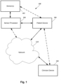
- Figure 1 illustrates one embodiment of a system 100 for monitoring an orthopedic implant and rehabilitation after orthopedic replacement surgery.
- the system 100 includes one or more sensors 102, an optional sensor processor 104, a patient device 106, a clinician device 108, and a network 110.
- the system may include fewer or more components, but the system typically includes the sensor(s) 102 and a processor (such as sensor processor 104, patient device 106, or clinician device 108) to communicate with the sensor(s) and provide information based on the sensor data.
- the one or more sensors 102 may be combined into a sensor module that may also include the sensor processor 104.
- the one or more sensors 102 and the optional sensor processor 104 can be implanted into the patient.
- the one or more sensors and the optional sensor processor 104 can be provided in a device that is external to the patient such as, for example, a device that is applied to the skin of the patient or is carried in a brace or other article or textile that is worn by the patient.
- at least one of the sensors are implanted and the optional sensor processor and, optionally, one or more sensors external to the patient.
- the solid lines indicate communication between components in at least some embodiments of the system. Dotted lines indicate alternative or additional modes of communication between components.
- the sensor processor 104 or sensors 102 may also communicate directly with the clinician device. Communications can include, but is not limited to, wireless communication, wired communication, optical communication, ultrasonic communication, or the combination thereof. Satellite communication, cellular communication, Bluetooth TM , near field communications (NFC), Infrared Data Association standard (IrDA), wireless fidelity (WiFi), and worldwide interoperability for microwave access (WiMAX) are non-limiting examples of wireless communication that can be used for communications. Ethernet, digital subscriber line (DSL), fiber to the home (FTTH), and plain old telephone service (POTS) are non-limiting examples of wired communication that can be used for communications.
- DSL digital subscriber line
- FTTH fiber to the home
- POTS plain old telephone service
- the network 110 can be any suitable type of network including, but not limited to, a personal area network (PAN), local area network (LAN), metropolitan area network (MAN), wide area network (WAN), the Internet, or any combination thereof. In at least some embodiments, the network 110 can be bypassed to provide direct connection between components. It will be understood that other devices, such as a server or server farm, memory storage device, or the like can be connected to the patient device 106 or clinician device 108 through the network 110 or directly. For example, a server may be coupled to the patient device 106 or clinician device 108 that stores patient or other medical information, applications, user interfaces, a web interface, or the like for access by the patient device 106 or clinician device 108.
- PAN personal area network
- LAN local area network
- MAN metropolitan area network
- WAN wide area network
- the Internet or any combination thereof.
- the network 110 can be bypassed to provide direct connection between components.
- other devices such as a server or server farm, memory storage device, or the like can be connected to the
- the patient device 106 and the clinician device 108 can be any of a variety of devices, such as computers (for example, a notebook computer, a mobile medical station or computer, a server, a mainframe computer, or a desktop computer), mobile devices (for example, a cellular phone or smartphone, personal digital assistant, or a tablet), or any other suitable device.
- the clinician device 108 can be incorporated into a medical station or system.
- FIG. 2 illustrates one embodiment of a computing device 201 for use as the patient device 106 or clinician device 108.
- the computing device 201 includes a processor 212 and a memory 214, a display 216, and an input device 218.
- the computing device 201 can be local to the user or can include components that are non-local to the computer including one or both of the processor 212 or memory 214 (or portions thereof).
- the user may operate a terminal that is connected to a non-local processor or memory.
- the computing device 201 can utilize any suitable processor 212 including one or more hardware processors that may be local to the user or non-local to the user or other components of the computing device.
- the processor 212 is configured to execute instructions provided to the processor. Such instructions can include any of the steps of methods or processes described herein.
- the memory 214 illustrates a type of computer-readable media, namely computer-readable storage media.
- Computer-readable storage media may include, but is not limited to, nonvolatile, non-transitory, removable, and non-removable media implemented in any method or technology for storage of information, such as computer readable instructions, data structures, program modules, or other data. Examples of computer-readable storage media include RAM, ROM, EEPROM, flash memory, or other memory technology, CD-ROM, digital versatile disks (“DVD”) or other optical storage, magnetic cassettes, magnetic tape, magnetic disk storage or other magnetic storage devices, or any other medium which can be used to store the desired information and which can be accessed by a computing device.
- Communication methods provide another type of computer readable media; namely communication media.
- Communication media typically embodies computer-readable instructions, data structures, program modules, or other data in a modulated data signal such as a carrier wave, data signal, or other transport mechanism and include any information delivery media.
- modulated data signal and “carrier-wave signal” includes a signal that has one or more of its characteristics set or changed in such a manner as to encode information, instructions, data, and the like, in the signal.
- communication media includes wired media such as twisted pair, coaxial cable, fiber optics, wave guides, and other wired media and wireless media such as acoustic, RF, infrared, Bluetooth TM , near field communication, and other wireless media.
- the display 216 can be any suitable display device, such as a monitor, screen, display, or the like, and can include a printer.
- the input device 218 can be, for example, a keyboard, mouse, touch screen, track ball, joystick, voice recognition system, camera, microphone, or any combination thereof, or the like.
- the sensor processor 104 can be any suitable processor including one or more hardware processors.
- the sensor processor 104 is configured to execute instructions provided to the processor.
- the sensor processor 104 is configured to receive sensor data from the sensor(s) and communicate with the patient device 106, network 110, clinician device 108, or any combination thereof.
- the sensor processor 104 may also process or analyze the sensor data and may have instructions stored thereon to perform such processing or analysis including, for example, instructions to perform the steps of any of the processing or analysis described herein.
- one or more of the sensor(s) 102 can each include a processor that perhaps some or all of the functions of the sensor processor 104.
- the one or more sensors 102 are provided to monitor the orthopedic implant and surrounding tissue or monitor rehabilitation after orthopedic surgery whether an implant was required or not, or to provide preparatory therapy in advance of a surgery, or any combination thereof.
- This disclosure will use an orthopedic knee implant as an example, but it will be understood that other joint implants, such as, for example, implants for the shoulder, hip, ankle, wrist, or any other joint, or any other orthopedic device, such as an orthopedic spinal implant, whether joint replacement, joint resurfacing, soft tissue reconstruction, debridement, limb correction surgery, ligament replacement, or the like.
- any suitable type of sensor 102 can be used including, but not limited to, accelerometers, magnetometers, gyroscopes, proximity sensors, infrared sensors, ultrasound sensors, thermistors or other temperature sensors, cameras, piezoelectric or other pressure sensors, sonar sensors, external fluid sensor, skin discoloration sensor, pH sensor, microphone, or the like or any combination thereof.
- the system 100 includes at least one, two, three, four, five, six, or more different types of sensors 102.
- the system may include at least one, two, three, four, five, six, eight, ten, or more sensors 102.
- the one or more sensors 102 can be used to measure, monitor, or otherwise observe one or more aspects of the orthopedic device, surrounding tissue, or patient activity, or the like.
- a system 100 can observe or measure one or more of these items or any
- One or more sensors may count steps or repetitions of an exercise or number of joint movements or other actions experienced by the sensor, and may be utilized to determine what type of exercise or movement is occurring. This can be used, for example, to monitor patient activity, monitor compliance with exercise therapy, or monitor possible signs of pain or other conditions that may hinder or aid rehabilitation.
- the sensor data may also be used to monitor changes in activity or trends in activity.
- One or more sensors may sense or detect or compute the range of motion of the sensor, joint, or other portion of the patient body or the flexion of the joint. This can be used, for example, to monitor patient rehabilitation, patient activity, monitor compliance with exercise therapy, or monitor possible signs of pain or other conditions that may hinder or aid rehabilitation. These sensors or other sensors may be used to monitor shock to, or impact on, the orthopedic device or tissue around the orthopedic device. The sensor data may also be used to monitor changes in range of motion or flexion or trends in range of motion or flexion.
- two proximity sensors can be implanted or placed externally on opposing sides of a joint.
- the distance between the two proximity sensors can be detected, measured, or otherwise observed.
- the distance between the two proximity sensors can be correlated to flexion or range of motion of the patient's joint.
- the variation in the distance between the two proximity sensors can be used to measure number of repetitions of joint motion or to monitor compliance with patient therapy.
- the variation in distance among repetitions or the trend in the variation among repetitions may be used to monitor improvement in joint flexibility or may indicate pain or other deleterious physical conditions of orthopedic implant or surrounding tissue. This information can be used to measure progress in the physical therapy following the surgery.
- one or more accelerometers can measure the acceleration from joint movement.
- a ratio of measured acceleration between accelerometers of known distance apart can be used to assess the joint movement and region of motion or flexion by calculating the center of rotation about which the device is being rotated. This information can be used for the same purposes as described in the preceding example.
- an accelerometer and 2) a gyroscope or magnetometer can be used to measure range of motion, rate of motion, number of repetitions, or the like. This information can be used for the same purposes as described in the preceding two examples.
- a single sensor such as an accelerometer, gyroscope, or magnetometer can be used to measure or otherwise observe range of motion, rate of motion, number of repetitions, or the like.
- these measurements or other observations are determined using the sensor data and one or more assumptions about the sensor or sensor data based on, for example, the recognition of patterns in the sensor data, the upper and lower limits of the range in the data collected, or the like. Such information can be used in a manner similar to that in the preceding three examples.
- One or more sensors may sense or detect or compute a temperature or a change in temperature or a temperature trend.
- the temperature may be a skin temperature or internal temperature of, for example, tissue near the orthopedic device.
- the temperature measurements may be used, for example, to indicate the possibility of inflammation or pain or another condition that may hinder rehabilitation or patient health.
- the temperature measurement may also be used, for example, to monitor if icing is being performed effectively, which can help reduce inflammation and aid healing.
- These sensors may also or alternatively be used to sense, detect, or measure a pulse, a change in pulse, trends in the patient's pulse, a pulse profile, or heart rate recovery after patient activity (such as exercise or other exertion).
- monitoring temperature and pulse can facilitate monitoring of the patient's health and possibility of inflammation or other deleterious condition.
- One or more sensors can sense or detect or compute particles or density of particles or a particle density trend. These sensors may also be used to sense the tissue surrounding the orthopedic device, detect wear or dimensional changes on the orthopedic device or surrounding tissue, or the like. Ultrasound and sonar sensors may also be used to determine how close other parts of the knee (or other joint) are to the implant.
- One or more sensors can sense or detect or compute pressure or load with or around the sensor or orthopedic device.
- the sensor data may also be used to monitor changes in range of pressure or load bearing or trends in pressure or load bearing.
- These sensors or other sensors may be used to monitor shock to, or impact on, the orthopedic device or tissue around the orthopedic device.
- a pressure or load bearing sensor may also be used to detect swelling of the tissue around the orthopedic implant.
- Multiple pressure or load bearing sensors may also be used to detect flexion (which may be indicated by a uniaxial stretching of the tissue) and swelling (which may be indicated by biaxial stretching of the tissue.)
- Power can be provided to the sensors 102 and optional sensor processor 104 using any suitable power source including, but not limited to, primary cells, rechargeable batteries, storage capacitors, other power storage devices, or the like or any combination thereof.
- the power can be provided by a kinetic energy power source that utilizes the movements of the patient's body to generate power for the components or to or to charge a battery or storage capacitor or other power storage device coupled to the components.
- power can be provided by an induction power source disposed on or adjacent the patient's body (such as, for example, disposed in a brace or other article of clothing worn by the patient or in a mat upon which the patient sits or sleeps) and radiates electromagnetic energy to the sensors or optional sensor processor to power these components or to charge a battery or storage capacitor or other power storage device coupled to the components.
- an induction power source disposed on or adjacent the patient's body (such as, for example, disposed in a brace or other article of clothing worn by the patient or in a mat upon which the patient sits or sleeps) and radiates electromagnetic energy to the sensors or optional sensor processor to power these components or to charge a battery or storage capacitor or other power storage device coupled to the components.
- Other wireless power sources can be used in place of the induction power source such as, for example, a wireless power source that utilizes ultrasound or WiFi or other rf power signals to generate power in the for charging a battery or storage capacitor or other power storage device.
- a charging port can be provided for charging the battery or storage capacitor or other power storage device from a source such as a wall socket. It will be understood that in some embodiments there may be multiple methods for providing power to the component or to a power storage device associated with the component. All of the sensors and optional sensor processor may be coupled to the same power source or some of the sensors (or even all of the sensors) and sensor processor may have individual power sources.
- the sensors and optional sensor processor can be active at all times to measure, monitor, or otherwise observe.
- one or more of the sensors and optional sensor processor can be active periodically (with a period of, for example, 15 or 30 seconds or 1, 5, 10, 15, or 30 minutes or 1, 2, 3, 4, 6, 12, or 24 hours) or randomly to measure, monitor, or otherwise observe.
- the period may be programmable.
- the period may be optionally altered based on data from one or more of the sensors.
- one or more of the sensors and optional sensor processor may be activated manually or automatically by the sensor module, patient device, clinician device, or other device.
- the sensors and optional sensor processor may have different activation schedules (continuous, periodic, random, or manual). For example, a sensor to measure temperature may do so periodically, a sensor to measure number of steps or movement of the joint may be continuous, and a sensor to measure range of motion may be activated manually by the sensor module, patient device, or clinician device when the patient performs rehabilitation exercises.
- Figure 3 illustrates a knee joint 350 having an orthopedic knee implant 352 and sensors 302a, 302b, 302c, 302d implanted around the knee joint 350.
- the orthopedic knee implant 352 can be made of, for example, surgical steel, carbon fiber, Kevlar fiber, or a combination thereof.
- the set of sensors can, for example, include a first proximity sensor 302a, a second proximity sensor 302b, a thermal and acoustic sensor 302c, and a shock sensor 302d. It will be understood that other or different sensors can be used.
- the thermal and acoustic sensor 302c can be directly coupled to a portion of the orthopedic knee implant 352 or disposed in the tissue away from the device.
- the thermal and acoustic sensor 302c can detect any unexpected contact between the component parts of the orthopedic knee implant 352. Any acoustic noise or vibrations that come from the orthopedic knee implant 352 can be sampled and recorded by the thermal and acoustic sensor 302c. The thermal and acoustic sensor 302c may also be used to measure temperature of the implant 352 or surrounding tissue.
- the shock sensor 302d can record or measure shocks or impacts to the implant 352. In at least some embodiments, the shock sensor 302d can be biased to only record shock or impact events over a preset threshold.
- the first proximity sensor 302a and the second proximity sensor 302b can be mounted along a centerline 212 of the joint to work in tandem.
- the distance between the first proximity sensor 302a and the second proximity sensor 302b can be detected and recorded.
- the distance between the first proximity sensor 302a and the second proximity sensor 302b can be correlated to the deflection of the orthopedic knee implant 352. This information can be used, for example, to measure progress in the physical therapy following the surgery to install the orthopedic knee implant 352. Other arrangements of sensors can be used to measure range of motion, as described herein.
- the proximity sensor 302a, 302b may also be used to observe or determine, for example, number of steps, number of joint movements, or exercise repetitions.
- the sensors 302a, 302b, 302c, 302d communicate with the sensor processor 104), patient device 106, or clinician device 108 of Figure 1 .
- the sensor processor may be implanted with the body of the patient or may be disposed outside the body.
- the patient can wear a knee brace that includes sensor processor and an optional induction power source used to power one or more of the sensors.
- FIG. 4 illustrates another knee joint 450 having an orthopedic knee implant 452 and sensors 402a, 402b implanted around the knee joint 450.
- the sensors 402a, 402b can be implanted in the tissue surrounding the knee joint, in the bone of the knee, or in the implant 452. If the orthopedic knee implant 452 is flexed in the direction of a deflection angle 454, by bending the knee, the separation distance 456 will be decreased until the flexing is reversed.
- the first proximity sensor 402a and the second proximity sensor 402b measure or otherwise observe the separation distance 456 which can then be used to determine the deflection angle 454.
- the cycling of the deflection angle 454 can also be used as a step counter. It will be understood that other or different sensors can be used instead of, or in addition to, proximity sensors 402a, 402b.
- FIG. 5 illustrates one example of an arrangement disposed around a finger joint 550 with a finger joint implant 552, proximity sensors 502a, 502b, temperature sensor 502c, and pulse sensor 502d.
- the proximity sensors 502a, 502b can provide information similar to the embodiments described with respect to Figures 3 and 4 .
- the temperature sensor 502c can be used to measure temperature of the implant 552 or surrounding tissue and the pulse sensor 502d can be used to measure the patient's pulse.
- Figure 6 illustrates one embodiment of an implantable sensor module 658 with one or more sensors 602a, 602b, a housing 660, a power source 662, a circuit carrier 664, a storage and communications unit 666, and a treatment unit 668.
- the one or more sensors can be any of the sensors described above including, for example, a proximity sensor and an acoustic sensor.
- Other embodiments of a sensor module can include more or fewer components.
- the housing 660 can be formed of materials that are resistant to ingress of body fluids including metals, polymers, or the like such as, for example, polycarbonate, stainless steel, Kevlar fibers, or the like.
- the one or more sensors 602a, 602b can be mounted on a circuit carrier 664 (for example, a printed circuit board, a printed flex circuit, a semiconductor substrate, a glass substrate, or a printed Mylar substrate) and coupled to the power source 662.
- the storage and communication unit 612 can save the sensor data in a non-volatile storage device and pass the saved data through wireless or wired communication to the sensor processor 104, patient device 106, or clinician device 108 illustrated in Figure 1 .
- the optional treatment unit 668 may provide vibrations or pulses or release drugs that can enhance bone growth.
- Figures 7A and 7B are top and bottom views, respectively, of one embodiment of a sensor module 758 that can be adhered, or otherwise placed adjacent, to the skin of the patient.
- the sensor module includes a housing 760, optional adhesive pad 770, sensors 702a, 702b, 702c, power source 762, communications unit 766, and sensor processor 704. It will be recognized that other sensor modules may have more or fewer sensors and that the sensors may be the same or of different types.
- the housing 760 can be made of any suitable material, such as plastic materials, and preferably has sufficient flexibility to fit comfortably on the patient's skin following the anatomical contours and to also flex as the patient moves. In at least some embodiments, the housing 760 is also water resistant to resist ingress of sweat, rain, and other fluids into the interior of the housing. In at least some embodiments, the housing 760 is sufficiently water resistant to allow the patient to shower with the sensor module 758 remaining attached to the skin of the patient and without any covering over the sensor module. In some embodiments, the housing 760 is sufficiently water resistant to allow the patient to bathe or swim without any covering over the sensor module 758.
- the housing 760 has a shape or indicia on the housing that visually indicates or suggests the orientation of the device when the housing is attached to the patient.
- One end of the device is narrower than the other end which indicates or suggests to the user that the narrow end is pointed toward the knee or other joint.
- the illustrated embodiment also features a power light 772 that is lit when the sensor module 758 is functioning to assure the patient that the device is operating.
- the power light 772 may also flash or change color to indicate device functions such as, for example, a low battery, pairing with another device (for example, the patient device 106, clinician device 108, or network 110 of Figure 1 ), actively taking readings using one or more of the sensors (particularly for sensors that are manually or periodically activated), alert the patient that it is time to perform exercises, change adhesives or the like.
- the illustrated embodiment also features a power button 774 that can be activated to turn the device on and, optionally, to turn the device off.
- the power button 774 may also be activated to manually direct one or more of the sensors to take readings.
- the optional adhesive pad 770 is designed to hold the sensor module 758 on the patient's skin.
- the adhesive pad 770 can have, for example, a substrate with adhesive on both sides of the substrate so that one side can be adhered to the patient's skin and the other side adhered to the housing 760.
- the adhesive pad 770 can be periodically replaced (for example, every 1, 2, 5, or 7 days or every 2, 3, 4, or more weeks) as the adhesive next to the patient's skin or the housing 760 may degrade or otherwise lose some or all of its adhesiveness.
- at least the adhesive to be adhered to the patient's skin is selected to prevent or resist causing skin irritation.
- the adhesive on both sides of the substrate is selected to be water resistant and resist losing adherence due to contact with sweat.
- the adhesive pad 770 extends around the circumference of the sensor module 758, but includes one or more openings so allow the housing 760 to make contact with the skin of the patient or access to the patient without an intervening portion of the adhesive pad 770.
- adhesive may be applied directly to the housing for adhering the housing directly to the skin.
- the sensor module instead of adhering the sensor module to the skin, the sensor module can be inserted into a brace or other item to be worn by the patient and hold the sensor module in place at the desired position on the body.
- This wearable item such as a brace, optionally includes an opening that allows the sensor module to make contact with the skin of the patient.
- the sensors 702a, 702b, 702c, power source 762, communications unit 766, and sensor processor 704 can be disposed within the housing 760.
- a portion of one or more of the sensors such as a temperature, pulse, or pressure sensor; moisture sensor, strain gage, may extend through the housing to provide contact with the skin or access to the patient without an intervening portion of the housing 760 or other parts of the sensor module 758.
- sensor 702a is an accelerometer
- sensor 702b is a gyroscope
- sensor 702c is a temperature sensor.
- the temperature sensor can be, for example, a thermistor or an infrared sensor.
- the accelerometer 702a and gyroscope 702b can be used to measure range of motion, number of steps, type of exercise, number of exercise repetitions or joint movements, and the like.
- the sensors 702a, 702b can both be accelerometers that are optionally in-line with each other to increase accuracy in range of motion observations, and can be further utilized in the calculation of the point about which the motion is rotating.
- the sensors include an accelerometer, a magnetometer, and a temperature sensor.
- any suitable sensor described above can be included in the sensor module and any combination of those sensors can be used in the sensor module. It is also understood that multiple sensor modules can be utilized together to provide data refinement or to provide comparative information, such as to show improvement in limp, or more accurately define the positions of both sides of the joint.
- the power source 762 can be a primary cell and may have an expected lifetime under normal usage of at least 1, 2, or 4 weeks or at least 1, 2, 3, 4, 6, 8, 10, 12, 15, 18, 24, months or more.
- the power source 762 is rechargeable using, for example, a recharge port in the sensor module 758 or is capable of being wirelessly charged such as with an inductive recharge device (such as an inductive mat or sleeve), or using WiFi or ultrasonic charging as described above.
- the power could be provided to the device by energy harvesting means, such as with cantilevered piezo reeds, a generator and pendulum setup, passive magnets rolling/sliding/bouncing through or by coils, or the like to convert some amount of kinetic energy into electrical energy to be used by the device.
- the power source 762 provides power to the sensors 702a, 702b, 702c, communications unit 766, sensor processor 704, and any other components in the sensor module.
- the communications unit 766 can be any suitable communications arrangement that can transmit information from the sensor processor 704 or sensors 702a, 702b, 702c to another device (such as the patient device 106, clinician device 108, or network 110 of Figure 1 .)
- the communications unit 766 can transmit this information by any suitable wired or wireless technique including, but not limited to, Bluetooth TM , near field communications, WiFi, infrared, radio frequency, acoustic, optical, or using a wired connection through a data port in the sensor module or any other communications technique presented herein or the like.
- Figures 8A and 8B illustrate another embodiment of a sensor module 858 without ( Figure 8A ) and with ( Figure 8B ) an adhesive pad 870.
- the sensor module 858 is similar to the sensor module 758 except in the shape of the adhesive pad 870 and that the housing 860 of this embodiment has pulling features 880 that facilitate gripping the sensor module 858 to more easily remove or pull the sensor module from the skin of the patient.
- Figure 9A illustrates another embodiments of a sensor module 958 with a housing 960 and an adhesive pad 970.
- the sensor module 958 is similar to the sensor module 758 except as described below.
- Figure 9B illustrates the housing 960 with gripping features that facilitate gripping the sensor module 958 to more easily remove or pull the sensor module from the skin of the patient.
- Figure 9C illustrates the adhesive pad 970 with one or more shaped locating features 982 attached to the adhesive pad and extending away from a substrate 971 of the adhesive pad.
- Figure 9D illustrates the bottom of the housing 960 with one or more shaped locating features 984 that are preferably complementary in shape to the locating features 982 of the adhesive pad 970.
- the locating features 982, 984 facilitate properly attached the adhesive pad 970 to the housing 960.
- a second sensor module can be used.
- the second sensor module can be placed on the same leg on the other side of the joint and the sensors in the two sensor module can be used to measure flexion angles, range of motion, and the like.
- the two sensor modules optionally can communicate with each other.
- a second sensor module may be placed on the other leg for use in detecting or observing limp or other gait deficiencies or placed on the torso to detect or observe body orientation.
- a second sensor module (or more additional sensor modules) may also be used when two or more replacements are implanted in the body, for example, with multiple joint or vertebra replacements, to detect or observe, for example, subluxations, changes or defects in posture, scoliosis, or the like.
- each of the locating features 982, 984 has a magnet to facilitate proper attachment and continued attachment of the housing 960 to the adhesive pad 970.
- one set of locating features 982, 984 may have a magnet and the other set have a magnetically attractive material.
- the adhesive pad 970 optionally has adhesive on the side of the pad containing the locating features 982, 984.
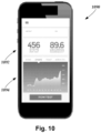
- FIG 10 illustrates one embodiment of a user interface 1090 for the patient device or clinician device.
- the illustrated user interface 1090 is particularly useful for a mobile device such as a smartphone or tablet.
- the user interface 1090 can provide information such as steps per day (or number of repetitions of an exercise or the like) and a temperature measurement as shown in section 1092.
- the user interface 1090 may also include a section 1092 that shows graphs of the data such as the hourly number of steps, as illustrated in Figure 10 .
- the illustrated user interface 1090 permits the user to select from other charts such as exercise history (labeled "ROM"), temperature, and number of impacts or shocks to the sensor module.
- ROM exercise history
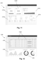
- Figure 11 illustrates a user interface 1190 that may be suitable for a computer or web interface.
- the illustrated user interface includes a region 1192 displaying the results of temperature measurements 1192a, step measurements 1192b, range of motion tests 1192c, specific exercises and tests 1192d, and adverse events 1192e.
- These results may include numerical information and graphical information.
- These results may also illustrate graphically or numerically the degree of success in performing exercises (see, for example, region 1092d) and may also illustrate the degree of compliance with rehabilitation activities (such as the number of exercise repetitions performed).
- Such an arrangement of information can facilitate monitoring or patient progress, identification of progress or lack of progress, identification of concerns (such as elevated temperature or elevated number of shocks or impacts), and the like.
- Figure 12 illustrates a user interface 1290 for a clinician to monitor multiple patients.
- the region 1292 includes information such as patient name, surgery date, sensor date and results of tests 1292a, number of adverse events, location of the orthopedic implant, and the like.
- the clinician may also track number of surgeries 1294, rate of successful rehabilitation 1296, and other suitable information.
- the user interfaces 1090, 1190, 1290 can be web or application interfaces that are accessible when the patient device or clinician device accesses a server for a content provider.
- the server or other servers or memory storage devices can store information for the web interface and may also store patient-specific information including patient identification data, sensor data or information derived from sensor data, patient or clinician comments or the like, or any other suitable data.
- the patient-specific information can be accessed from the patient device, clinician device or other device which, in some embodiments, may require providing credentials (e.g., username or password or both) to access the information.
Landscapes
- Health & Medical Sciences (AREA)
- Life Sciences & Earth Sciences (AREA)
- Engineering & Computer Science (AREA)
- Physics & Mathematics (AREA)
- Surgery (AREA)
- Public Health (AREA)
- Heart & Thoracic Surgery (AREA)
- General Health & Medical Sciences (AREA)
- Biophysics (AREA)
- Pathology (AREA)
- Animal Behavior & Ethology (AREA)
- Biomedical Technology (AREA)
- Veterinary Medicine (AREA)
- Medical Informatics (AREA)
- Molecular Biology (AREA)
- Dentistry (AREA)
- Oral & Maxillofacial Surgery (AREA)
- Physiology (AREA)
- Nuclear Medicine, Radiotherapy & Molecular Imaging (AREA)
- Computer Networks & Wireless Communication (AREA)
- Radar, Positioning & Navigation (AREA)
- Remote Sensing (AREA)
- Radiology & Medical Imaging (AREA)
- Orthopedic Medicine & Surgery (AREA)
- General Physics & Mathematics (AREA)
- Rheumatology (AREA)
- Optics & Photonics (AREA)
- Geometry (AREA)
- Physical Education & Sports Medicine (AREA)
- Cardiology (AREA)
- Automation & Control Theory (AREA)
- Transplantation (AREA)
- Measuring And Recording Apparatus For Diagnosis (AREA)
- Rehabilitation Tools (AREA)
- Measurement Of The Respiration, Hearing Ability, Form, And Blood Characteristics Of Living Organisms (AREA)
- Prostheses (AREA)
Description
- This application claims the benefit of
U.S. Provisional Patent Application serial number 62/136,892 filed March 23, 2015 - The present invention is directed to the area of orthopedic implants and rehabilitation. The present invention is also directed to systems and methods for monitoring an orthopedic implant and rehabilitation after orthopedic replacement surgery.
- Joint replacement surgery is a common orthopedic procedure for joints such as the shoulder, hip, knee, ankle, and wrist. In situations where the patient has worn-out or damaged a j oint, it is possible to replace the joint with an implant that can merge with the skeletal structure and restore pain free movement and function. Prior to implanting prosthetic components in a joint of a patient, a surgeon generally resects at least a portion of the patient's native bone in order to create a platform, recess, or cavity for receiving at least a portion of the prosthetic components being implanted. During the process of implanting the prosthetic components muscles and tendons must be repositioned and reattached.
- The patient must go through physical therapy in order to recover from this major surgery. The patient must exercise regularly as well as push for flexibility and balance in muscles that have been displaced. While the goal is to have the patient extend their range of motion, there can be an increased risk of falls or over-extension that can damage the implant and injure the patient. If the patient does not push their rehabilitation and achieve the needed range of motion, they will find themselves with a stiff joint which may require an additional surgical operation (MUA - Manipulation Under Anesthesia) to achieve an adequate range of motion to maintain their active lifestyle. Measuring or monitoring the progress of the physical therapy can be problematic but is very useful for maintaining the patient's dedication and participation.
- Documents
US 2011/245711 A1 andUS 2012/143135 A1 disclose a system for monitoring a joint of a patient according to prior art. - One embodiment is a system for monitoring a j oint of a patient according to claim 1.
- In at least some embodiments, the at least one communication unit includes a sensor processor to receive the sensor data and a wireless communications unit to wirelessly transmit the sensor information to or through the external device. In at least some embodiments, at least one of the sensors is configured and arranged to be implanted in the patient.
- In at least some embodiments, the system further includes a sensor module having a housing, the sensors disposed in the housing, and the at least one communication unit disposed in the housing, where the sensor module is configured and arranged to be disposed adjacent skin of the patient to monitor the joint. In at least some embodiments, the sensor module further includes an adhesive pad coupleable to the housing to adhesively adhere the sensor module to the skin of the patient for at least one hour. In at least some embodiments, the system further includes a wearable article to receive the sensor module within the wearable article and to be worn by the patient so that the sensor module is disposed near the joint.
- In at least some embodiments, the sensors include at least one sensor to provide sensor data that can be processed to determine a range of motion of the joint. In at least some embodiments, the at least one sensor includes a first accelerometer in combination with at least one of a second accelerometer, a gyroscope, or a magnetometer. In at least some embodiments, the sensors include at least two proximity sensors to provide sensor data that can be processed to determine a number of repetitions of joint movement. In at least some embodiments, the sensors include at least one temperature sensor or pulse sensor.
- In at least some embodiments, the system further includes a patient device to receive the sensor information from the at least one communications module and to process the sensor information and display the processed information for viewing by the patient. In at least some embodiments, the system further includes a clinician device to receive the sensor information from the at least one communications module or from a patient device and to process the sensor information and display the processed information for viewing by a clinician.
- Another embodiment is a sensor module that includes a housing to be disposed near a joint of a patient and adjacent to skin of the patient; multiple sensors disposed within the housing; a sensor processor disposed within the housing and coupled to the plurality of sensors to receive sensor data from the plurality of sensors; and a communications unit disposed within the housing and coupled to the sensor processor to transmit sensor information, based on the sensor data, to an external device. The sensors include at least one sensor to provide sensor data that can be processed to determine a range of motion of the joint;
- In at least some embodiments, the sensor module further includes an adhesive pad coupleable to the housing to adhesively adhere the sensor module to the skin of the patient for at least one hour. In at least some embodiments, the adhesive pad includes at least one first locating feature and the housing includes at least one second locating feature having a shape complementary to a shape of the at least one first locating feature to facilitate alignment of the adhesive pad with the housing. In at least some embodiments, one of the at least one first locating feature or the at least one second locating feature includes a magnet and another one of the at least one locating feature or the at least one second locating feature includes a second magnet or a magnetically attractive material to facilitate coupling of the adhesive pad to the housing.
- In at least some embodiments, the sensor module further includes a wearable article to receive the housing of the sensor module within the wearable article and to be worn by the patient so that the housing of the sensor module is disposed near the joint.
- In at least some embodiments, the sensors include a first accelerometer in combination with at least one of a second accelerometer, a gyroscope, or a magnetometer. In at least some embodiments, the sensors include at least two proximity sensors configured and arranged to provide sensor data that can be processed to determine a number of repetitions of joint movement. In at least some embodiments, the sensors include at least one temperature sensor or pulse sensor.
- A further embodiment is a system for monitoring rehabilitation. The system includes multiple sensors to be disposed near a rehabilitation site on a patient to measure or observe actions or physical quantities associated with the rehabilitation; and at least one communications module coupled to the sensors to receive data from the sensors and to transmit sensor information to an external device.
- Yet another embodiment is a sensor module including a housing to be disposed near a rehabilitation site of a patient and adjacent to skin of the patient; multiple sensors disposed within the housing; a sensor processor disposed within the housing and coupled to the sensors to receive sensor data from the sensors; and a communications unit disposed within the housing and coupled to the sensor processor to transmit sensor information, based on the sensor data, to an external device. The sensors include at least one sensor configured and arranged to provide sensor data that can be processed to determine a range of motion at the rehabilitation site.
- Non-limiting and non-exhaustive embodiments of the present invention are described with reference to the following drawings. In the drawings, like reference numerals refer to like parts throughout the various figures unless otherwise specified.
- For a better understanding of the present invention, reference will be made to the following Detailed Description, which is to be read in association with the accompanying drawings, wherein:
-
FIG. 1 is a schematic diagram of one embodiment of a system for monitoring rehabilitation of a patient after implant surgery, according to the invention; -
FIG. 2 is a schematic diagram of one embodiment of a computing device for use in the system ofFIG. 1 , according to the invention; -
FIG. 3 is a schematic diagram of one embodiment of components of the system ofFIG. 1 implanted near a knee replacement implant, according to the invention; -
FIG. 4 is a schematic diagram of another embodiment of components of the system ofFIG. 1 implanted near a knee replacement implant, according to the invention; -
FIG. 5 is a schematic diagram of one embodiment of components of the system ofFIG. 1 implanted near a finger joint replacement implant, according to the invention; -
FIG. 6 is a schematic diagram of one embodiment of a sensor module that contains sensors for monitoring rehabilitation of a patient after implant surgery, according to the invention; -
FIG. 7A is a top view of a second embodiment of a sensor module that contains sensors for monitoring rehabilitation of a patient after implant surgery, according to the invention; -
FIG. 7B is a bottom view of the sensor module ofFIG. 7A , according to the invention; -
FIG. 8A is a top view of a third embodiment of a sensor module that contains sensors for monitoring rehabilitation of a patient after implant surgery, according to the invention; -
FIG. 8B is a top view of the sensor module ofFIG. 8A with an adhesive pad, according to the invention; -
FIG. 9A is a top view of a fourth embodiment of a sensor module that contains sensors for monitoring rehabilitation of a patient after implant surgery, according to the invention; -
FIG. 9B is a top view of the sensor module ofFIG. 8A without the adhesive pad, according to the invention; -
FIG. 9C is a top view of one embodiment of an adhesive pad for the sensor module ofFIG. 8A , according to the invention; -
FIG. 9D is a bottom view of one embodiment of the sensor module ofFIG. 9A for use with the adhesive pad ofFIG. 9C , according to the invention; -
FIG. 10 is a diagram of one embodiment of a user interface for a mobile device to display information obtained from a sensor module, according to the invention; -
FIG. 11 is a diagram of another embodiment of a user interface to display information obtained from a sensor module, according to the invention; and -
FIG. 12 is a diagram of a third embodiment of a user interface for a mobile device to display information obtained from a sensor module, according to the invention. - The present invention is directed to the area of orthopedic implants and rehabilitation. The present invention is also directed to systems and methods for monitoring an orthopedic implant and rehabilitation after orthopedic replacement surgery.
- A system, as described herein, can be used to monitor the healing process of the patient as well as monitor or verify the extent of the patient's activity. The system includes one or more sensors that can communicate with a processor that can produce information, based on the sensor readings and data, that can facilitate the patient or another user, such as a clinician, doctor, or physical therapist, monitoring the patient's activity, the status of the orthopedic implant or surrounding tissues, or the effects of rehabilitation or other therapy. It will be understood, however, that the systems, devices, and methods described herein can be used in the context of other surgeries or even rehabilitation without surgical intervention. The sensors, described below, are placed near a rehabilitation site, such as a surgical site or the body portion to be rehabilitated.
- The system may also provide alerts if patient tissue becomes inflamed or if the effectiveness of, or compliance to, rehabilitation therapy is insufficient. In at least some embodiments, at least one sensor is implanted and, in some embodiments, all of the sensors may be implanted. In at least some embodiments, at least one sensor is external to the patient and, in some embodiments, all of the sensors are external. For example, one or more sensors may be provided on a device that is applied to the skin of the patient or is carried in a brace or other article (for example, socks, shirt, shorts, pants, glove, or the like) that is worn by the patient.
- In at least some embodiments, the one or more sensors communicate with a sensor processor on the device containing or near the sensors. In at least some embodiments, the sensor processor, or, alternatively or additionally, the sensors, communicate with a processor of a patient device, such as a mobile phone, tablet, computer or the like, or with a processor of a clinician device, such as a mobile phone, tablet, computer or the like.
-
Figure 1 illustrates one embodiment of asystem 100 for monitoring an orthopedic implant and rehabilitation after orthopedic replacement surgery. Thesystem 100 includes one ormore sensors 102, anoptional sensor processor 104, apatient device 106, aclinician device 108, and anetwork 110. In other embodiments, the system may include fewer or more components, but the system typically includes the sensor(s) 102 and a processor (such assensor processor 104,patient device 106, or clinician device 108) to communicate with the sensor(s) and provide information based on the sensor data. In at least some embodiments, the one ormore sensors 102 may be combined into a sensor module that may also include thesensor processor 104. - In at least some embodiments, the one or
more sensors 102 and theoptional sensor processor 104 can be implanted into the patient. In other embodiments, the one or more sensors and theoptional sensor processor 104 can be provided in a device that is external to the patient such as, for example, a device that is applied to the skin of the patient or is carried in a brace or other article or textile that is worn by the patient. In yet other embodiments, at least one of the sensors (or all of the sensors) are implanted and the optional sensor processor and, optionally, one or more sensors external to the patient. - In
Figure 1 , the solid lines indicate communication between components in at least some embodiments of the system. Dotted lines indicate alternative or additional modes of communication between components. In addition to the communication illustrated inFigure 1 , in at least some embodiments, thesensor processor 104 orsensors 102 may also communicate directly with the clinician device. Communications can include, but is not limited to, wireless communication, wired communication, optical communication, ultrasonic communication, or the combination thereof. Satellite communication, cellular communication, Bluetooth™, near field communications (NFC), Infrared Data Association standard (IrDA), wireless fidelity (WiFi), and worldwide interoperability for microwave access (WiMAX) are non-limiting examples of wireless communication that can be used for communications. Ethernet, digital subscriber line (DSL), fiber to the home (FTTH), and plain old telephone service (POTS) are non-limiting examples of wired communication that can be used for communications. - The
network 110 can be any suitable type of network including, but not limited to, a personal area network (PAN), local area network (LAN), metropolitan area network (MAN), wide area network (WAN), the Internet, or any combination thereof. In at least some embodiments, thenetwork 110 can be bypassed to provide direct connection between components. It will be understood that other devices, such as a server or server farm, memory storage device, or the like can be connected to thepatient device 106 orclinician device 108 through thenetwork 110 or directly. For example, a server may be coupled to thepatient device 106 orclinician device 108 that stores patient or other medical information, applications, user interfaces, a web interface, or the like for access by thepatient device 106 orclinician device 108. - The
patient device 106 and theclinician device 108 can be any of a variety of devices, such as computers (for example, a notebook computer, a mobile medical station or computer, a server, a mainframe computer, or a desktop computer), mobile devices (for example, a cellular phone or smartphone, personal digital assistant, or a tablet), or any other suitable device. In at least some embodiments, theclinician device 108 can be incorporated into a medical station or system. -
Figure 2 illustrates one embodiment of acomputing device 201 for use as thepatient device 106 orclinician device 108. Thecomputing device 201 includes aprocessor 212 and amemory 214, adisplay 216, and aninput device 218. Thecomputing device 201 can be local to the user or can include components that are non-local to the computer including one or both of theprocessor 212 or memory 214 (or portions thereof). For example, in some embodiments, the user may operate a terminal that is connected to a non-local processor or memory. - The
computing device 201 can utilize anysuitable processor 212 including one or more hardware processors that may be local to the user or non-local to the user or other components of the computing device. Theprocessor 212 is configured to execute instructions provided to the processor. Such instructions can include any of the steps of methods or processes described herein. - Any
suitable memory 214 can be used for thecomputing device 212. Thememory 214 illustrates a type of computer-readable media, namely computer-readable storage media. Computer-readable storage media may include, but is not limited to, nonvolatile, non-transitory, removable, and non-removable media implemented in any method or technology for storage of information, such as computer readable instructions, data structures, program modules, or other data. Examples of computer-readable storage media include RAM, ROM, EEPROM, flash memory, or other memory technology, CD-ROM, digital versatile disks ("DVD") or other optical storage, magnetic cassettes, magnetic tape, magnetic disk storage or other magnetic storage devices, or any other medium which can be used to store the desired information and which can be accessed by a computing device. - Communication methods provide another type of computer readable media; namely communication media. Communication media typically embodies computer-readable instructions, data structures, program modules, or other data in a modulated data signal such as a carrier wave, data signal, or other transport mechanism and include any information delivery media. The terms "modulated data signal," and "carrier-wave signal" includes a signal that has one or more of its characteristics set or changed in such a manner as to encode information, instructions, data, and the like, in the signal. By way of example, communication media includes wired media such as twisted pair, coaxial cable, fiber optics, wave guides, and other wired media and wireless media such as acoustic, RF, infrared, Bluetooth™, near field communication, and other wireless media.
- The
display 216 can be any suitable display device, such as a monitor, screen, display, or the like, and can include a printer. Theinput device 218 can be, for example, a keyboard, mouse, touch screen, track ball, joystick, voice recognition system, camera, microphone, or any combination thereof, or the like. - Returning to
Figure 1 , thesensor processor 104 can be any suitable processor including one or more hardware processors. Thesensor processor 104 is configured to execute instructions provided to the processor. Thesensor processor 104 is configured to receive sensor data from the sensor(s) and communicate with thepatient device 106,network 110,clinician device 108, or any combination thereof. Optionally, thesensor processor 104 may also process or analyze the sensor data and may have instructions stored thereon to perform such processing or analysis including, for example, instructions to perform the steps of any of the processing or analysis described herein. In at least some embodiments, one or more of the sensor(s) 102 can each include a processor that perhaps some or all of the functions of thesensor processor 104. - The one or
more sensors 102 are provided to monitor the orthopedic implant and surrounding tissue or monitor rehabilitation after orthopedic surgery whether an implant was required or not, or to provide preparatory therapy in advance of a surgery, or any combination thereof. This disclosure will use an orthopedic knee implant as an example, but it will be understood that other joint implants, such as, for example, implants for the shoulder, hip, ankle, wrist, or any other joint, or any other orthopedic device, such as an orthopedic spinal implant, whether joint replacement, joint resurfacing, soft tissue reconstruction, debridement, limb correction surgery, ligament replacement, or the like. - Any suitable type of
sensor 102 can be used including, but not limited to, accelerometers, magnetometers, gyroscopes, proximity sensors, infrared sensors, ultrasound sensors, thermistors or other temperature sensors, cameras, piezoelectric or other pressure sensors, sonar sensors, external fluid sensor, skin discoloration sensor, pH sensor, microphone, or the like or any combination thereof. In at least some embodiments, thesystem 100 includes at least one, two, three, four, five, six, or more different types ofsensors 102. The system may include at least one, two, three, four, five, six, eight, ten, ormore sensors 102. - The one or
more sensors 102 can be used to measure, monitor, or otherwise observe one or more aspects of the orthopedic device, surrounding tissue, or patient activity, or the like. The following are examples of observations or measurements that can be made or interpreted using one or more of the sensors: number of steps, repetitions of an exercise, repetitions of joint movement (e.g., joint pivoting), type of exercise being performed, or other actions; stability, or lack thereof; flexion angle or range of motion; rate of motion; temperature of skin or internal tissues; pulse or pulse profile or heart rate recovery time after activity; particles in a joint space; ultrasound images, flow measurements, or Doppler measurements; sonar images, flow measurements, or Doppler measurements; pressure or load bearing measurements; detection of a limp or body orientation (e.g., subluxation, posture, scoliosis) or a change in body orientation; joint shock or impact monitoring; sleep profile or rest duration; gait analysis, body/limb/joint alignments; or the like. Asystem 100 can observe or measure one or more of these items or any combination of the items. - The following provides further details on some of these measurements or observations. One or more sensors (for example, accelerometers, gyroscopes, magnetometers, proximity sensors, or the like) may count steps or repetitions of an exercise or number of joint movements or other actions experienced by the sensor, and may be utilized to determine what type of exercise or movement is occurring. This can be used, for example, to monitor patient activity, monitor compliance with exercise therapy, or monitor possible signs of pain or other conditions that may hinder or aid rehabilitation. The sensor data may also be used to monitor changes in activity or trends in activity.
- One or more sensors (for example, accelerometers, gyroscopes, magnetometers, proximity sensors, or the like) may sense or detect or compute the range of motion of the sensor, joint, or other portion of the patient body or the flexion of the joint. This can be used, for example, to monitor patient rehabilitation, patient activity, monitor compliance with exercise therapy, or monitor possible signs of pain or other conditions that may hinder or aid rehabilitation. These sensors or other sensors may be used to monitor shock to, or impact on, the orthopedic device or tissue around the orthopedic device. The sensor data may also be used to monitor changes in range of motion or flexion or trends in range of motion or flexion.
- As an illustrative example, two proximity sensors (for example, a magnetometer and a magnet - such as a permanent magnet, electromagnet, or polymagnet or the like) can be implanted or placed externally on opposing sides of a joint. The distance between the two proximity sensors can be detected, measured, or otherwise observed. The distance between the two proximity sensors can be correlated to flexion or range of motion of the patient's joint. The variation in the distance between the two proximity sensors can be used to measure number of repetitions of joint motion or to monitor compliance with patient therapy. The variation in distance among repetitions or the trend in the variation among repetitions may be used to monitor improvement in joint flexibility or may indicate pain or other deleterious physical conditions of orthopedic implant or surrounding tissue. This information can be used to measure progress in the physical therapy following the surgery.
- As another illustrative example, one or more accelerometers can measure the acceleration from joint movement. A ratio of measured acceleration between accelerometers of known distance apart can be used to assess the joint movement and region of motion or flexion by calculating the center of rotation about which the device is being rotated. This information can be used for the same purposes as described in the preceding example.
- In another illustrative example, 1) an accelerometer and 2) a gyroscope or magnetometer (which indicates direction relative to magnetic north) can be used to measure range of motion, rate of motion, number of repetitions, or the like. This information can be used for the same purposes as described in the preceding two examples.
- In another illustrative example, a single sensor such as an accelerometer, gyroscope, or magnetometer can be used to measure or otherwise observe range of motion, rate of motion, number of repetitions, or the like. In at least some embodiments, these measurements or other observations are determined using the sensor data and one or more assumptions about the sensor or sensor data based on, for example, the recognition of patterns in the sensor data, the upper and lower limits of the range in the data collected, or the like. Such information can be used in a manner similar to that in the preceding three examples.
- One or more sensors (for example, thermistors or infrared sensors) may sense or detect or compute a temperature or a change in temperature or a temperature trend. The temperature may be a skin temperature or internal temperature of, for example, tissue near the orthopedic device. The temperature measurements may be used, for example, to indicate the possibility of inflammation or pain or another condition that may hinder rehabilitation or patient health. The temperature measurement may also be used, for example, to monitor if icing is being performed effectively, which can help reduce inflammation and aid healing. These sensors may also or alternatively be used to sense, detect, or measure a pulse, a change in pulse, trends in the patient's pulse, a pulse profile, or heart rate recovery after patient activity (such as exercise or other exertion). In addition, when a joint is immobilized by a cast, monitoring temperature and pulse can facilitate monitoring of the patient's health and possibility of inflammation or other deleterious condition.
- One or more sensors (for example, ultrasound or sonar sensors or cameras or the like) can sense or detect or compute particles or density of particles or a particle density trend. These sensors may also be used to sense the tissue surrounding the orthopedic device, detect wear or dimensional changes on the orthopedic device or surrounding tissue, or the like. Ultrasound and sonar sensors may also be used to determine how close other parts of the knee (or other joint) are to the implant.
- One or more sensors (for example, piezoelectric, strain gage, or other pressure or load bearing sensors) can sense or detect or compute pressure or load with or around the sensor or orthopedic device. The sensor data may also be used to monitor changes in range of pressure or load bearing or trends in pressure or load bearing. These sensors or other sensors may be used to monitor shock to, or impact on, the orthopedic device or tissue around the orthopedic device. A pressure or load bearing sensor may also be used to detect swelling of the tissue around the orthopedic implant. Multiple pressure or load bearing sensors may also be used to detect flexion (which may be indicated by a uniaxial stretching of the tissue) and swelling (which may be indicated by biaxial stretching of the tissue.)
- Power can be provided to the
sensors 102 andoptional sensor processor 104 using any suitable power source including, but not limited to, primary cells, rechargeable batteries, storage capacitors, other power storage devices, or the like or any combination thereof. In some embodiments, the power can be provided by a kinetic energy power source that utilizes the movements of the patient's body to generate power for the components or to or to charge a battery or storage capacitor or other power storage device coupled to the components. In some embodiments, power can be provided by an induction power source disposed on or adjacent the patient's body (such as, for example, disposed in a brace or other article of clothing worn by the patient or in a mat upon which the patient sits or sleeps) and radiates electromagnetic energy to the sensors or optional sensor processor to power these components or to charge a battery or storage capacitor or other power storage device coupled to the components. Other wireless power sources can be used in place of the induction power source such as, for example, a wireless power source that utilizes ultrasound or WiFi or other rf power signals to generate power in the for charging a battery or storage capacitor or other power storage device. - In addition, for sensors or optional sensor processor disposed outside the body, a charging port can be provided for charging the battery or storage capacitor or other power storage device from a source such as a wall socket. It will be understood that in some embodiments there may be multiple methods for providing power to the component or to a power storage device associated with the component. All of the sensors and optional sensor processor may be coupled to the same power source or some of the sensors (or even all of the sensors) and sensor processor may have individual power sources.
- In at least some embodiments, the sensors and optional sensor processor can be active at all times to measure, monitor, or otherwise observe. In other embodiments, one or more of the sensors and optional sensor processor can be active periodically (with a period of, for example, 15 or 30 seconds or 1, 5, 10, 15, or 30 minutes or 1, 2, 3, 4, 6, 12, or 24 hours) or randomly to measure, monitor, or otherwise observe. Optionally, the period may be programmable. In addition, the period may be optionally altered based on data from one or more of the sensors. In yet other embodiments, one or more of the sensors and optional sensor processor may be activated manually or automatically by the sensor module, patient device, clinician device, or other device. In at least some embodiments, the sensors and optional sensor processor may have different activation schedules (continuous, periodic, random, or manual). For example, a sensor to measure temperature may do so periodically, a sensor to measure number of steps or movement of the joint may be continuous, and a sensor to measure range of motion may be activated manually by the sensor module, patient device, or clinician device when the patient performs rehabilitation exercises.
-
Figure 3 illustrates a knee joint 350 having anorthopedic knee implant 352 andsensors knee joint 350. Theorthopedic knee implant 352 can be made of, for example, surgical steel, carbon fiber, Kevlar fiber, or a combination thereof. To monitor the recovery of the joint 350, the set of sensors can, for example, include afirst proximity sensor 302a, asecond proximity sensor 302b, a thermal andacoustic sensor 302c, and ashock sensor 302d. It will be understood that other or different sensors can be used. The thermal andacoustic sensor 302c can be directly coupled to a portion of theorthopedic knee implant 352 or disposed in the tissue away from the device. The thermal andacoustic sensor 302c can detect any unexpected contact between the component parts of theorthopedic knee implant 352. Any acoustic noise or vibrations that come from theorthopedic knee implant 352 can be sampled and recorded by the thermal andacoustic sensor 302c. The thermal andacoustic sensor 302c may also be used to measure temperature of theimplant 352 or surrounding tissue. - The
shock sensor 302d can record or measure shocks or impacts to theimplant 352. In at least some embodiments, theshock sensor 302d can be biased to only record shock or impact events over a preset threshold. - In at least some embodiments, the
first proximity sensor 302a and thesecond proximity sensor 302b can be mounted along acenterline 212 of the joint to work in tandem. The distance between thefirst proximity sensor 302a and thesecond proximity sensor 302b can be detected and recorded. The distance between thefirst proximity sensor 302a and thesecond proximity sensor 302b can be correlated to the deflection of theorthopedic knee implant 352. This information can be used, for example, to measure progress in the physical therapy following the surgery to install theorthopedic knee implant 352. Other arrangements of sensors can be used to measure range of motion, as described herein. Theproximity sensor - The
sensors patient device 106, orclinician device 108 ofFigure 1 . The sensor processor may be implanted with the body of the patient or may be disposed outside the body. For example, the patient can wear a knee brace that includes sensor processor and an optional induction power source used to power one or more of the sensors. - It will be recognized that other arrangements of sensors can be implanted during the surgery for placement of the
orthopedic knee implant 352.Figure 4 illustrates another knee joint 450 having anorthopedic knee implant 452 andsensors knee joint 450. Thesensors implant 452. If theorthopedic knee implant 452 is flexed in the direction of adeflection angle 454, by bending the knee, theseparation distance 456 will be decreased until the flexing is reversed. Thefirst proximity sensor 402a and thesecond proximity sensor 402b measure or otherwise observe theseparation distance 456 which can then be used to determine thedeflection angle 454. In at least some embodiments, the cycling of thedeflection angle 454 can also be used as a step counter. It will be understood that other or different sensors can be used instead of, or in addition to,proximity sensors - Similar techniques and arrangements can be used with other joints including, but not limited to, the finger j oint, wrist j oint, elbow j oint, shoulder j oint, hip joint, ankle joint, or toe joint.
Figure 5 illustrates one example of an arrangement disposed around a finger joint 550 with a fingerjoint implant 552,proximity sensors temperature sensor 502c, andpulse sensor 502d. Theproximity sensors Figures 3 and 4 . Thetemperature sensor 502c can be used to measure temperature of theimplant 552 or surrounding tissue and thepulse sensor 502d can be used to measure the patient's pulse. -
Figure 6 illustrates one embodiment of animplantable sensor module 658 with one ormore sensors housing 660, apower source 662, acircuit carrier 664, a storage andcommunications unit 666, and atreatment unit 668. The one or more sensors can be any of the sensors described above including, for example, a proximity sensor and an acoustic sensor. Other embodiments of a sensor module can include more or fewer components. - The
housing 660, can be formed of materials that are resistant to ingress of body fluids including metals, polymers, or the like such as, for example, polycarbonate, stainless steel, Kevlar fibers, or the like. The one ormore sensors power source 662. The storage and communication unit 612 can save the sensor data in a non-volatile storage device and pass the saved data through wireless or wired communication to thesensor processor 104,patient device 106, orclinician device 108 illustrated inFigure 1 . Theoptional treatment unit 668 may provide vibrations or pulses or release drugs that can enhance bone growth. -
Figures 7A and 7B are top and bottom views, respectively, of one embodiment of asensor module 758 that can be adhered, or otherwise placed adjacent, to the skin of the patient. The sensor module includes ahousing 760, optionaladhesive pad 770,sensors power source 762,communications unit 766, andsensor processor 704. It will be recognized that other sensor modules may have more or fewer sensors and that the sensors may be the same or of different types. - The
housing 760 can be made of any suitable material, such as plastic materials, and preferably has sufficient flexibility to fit comfortably on the patient's skin following the anatomical contours and to also flex as the patient moves. In at least some embodiments, thehousing 760 is also water resistant to resist ingress of sweat, rain, and other fluids into the interior of the housing. In at least some embodiments, thehousing 760 is sufficiently water resistant to allow the patient to shower with thesensor module 758 remaining attached to the skin of the patient and without any covering over the sensor module. In some embodiments, thehousing 760 is sufficiently water resistant to allow the patient to bathe or swim without any covering over thesensor module 758. - According to the invention, the
housing 760 has a shape or indicia on the housing that visually indicates or suggests the orientation of the device when the housing is attached to the patient. One end of the device is narrower than the other end which indicates or suggests to the user that the narrow end is pointed toward the knee or other joint. - The illustrated embodiment also features a
power light 772 that is lit when thesensor module 758 is functioning to assure the patient that the device is operating. In some embodiments, thepower light 772 may also flash or change color to indicate device functions such as, for example, a low battery, pairing with another device (for example, thepatient device 106,clinician device 108, ornetwork 110 ofFigure 1 ), actively taking readings using one or more of the sensors (particularly for sensors that are manually or periodically activated), alert the patient that it is time to perform exercises, change adhesives or the like. - The illustrated embodiment also features a
power button 774 that can be activated to turn the device on and, optionally, to turn the device off. In at least some embodiments, thepower button 774 may also be activated to manually direct one or more of the sensors to take readings. - The optional
adhesive pad 770 is designed to hold thesensor module 758 on the patient's skin. Theadhesive pad 770 can have, for example, a substrate with adhesive on both sides of the substrate so that one side can be adhered to the patient's skin and the other side adhered to thehousing 760. In at least some embodiments, theadhesive pad 770 can be periodically replaced (for example, every 1, 2, 5, or 7 days or every 2, 3, 4, or more weeks) as the adhesive next to the patient's skin or thehousing 760 may degrade or otherwise lose some or all of its adhesiveness. Preferably, at least the adhesive to be adhered to the patient's skin is selected to prevent or resist causing skin irritation. Preferably, the adhesive on both sides of the substrate is selected to be water resistant and resist losing adherence due to contact with sweat. In at least some embodiments, theadhesive pad 770 extends around the circumference of thesensor module 758, but includes one or more openings so allow thehousing 760 to make contact with the skin of the patient or access to the patient without an intervening portion of theadhesive pad 770. - In the invention, instead of the
adhesive pad 770, adhesive may be applied directly to the housing for adhering the housing directly to the skin. In yet other embodiments, instead of adhering the sensor module to the skin, the sensor module can be inserted into a brace or other item to be worn by the patient and hold the sensor module in place at the desired position on the body. This wearable item, such as a brace, optionally includes an opening that allows the sensor module to make contact with the skin of the patient. - The
sensors power source 762,communications unit 766, andsensor processor 704 can be disposed within thehousing 760. In some embodiments, a portion of one or more of the sensors, such as a temperature, pulse, or pressure sensor; moisture sensor, strain gage, may extend through the housing to provide contact with the skin or access to the patient without an intervening portion of thehousing 760 or other parts of thesensor module 758. In some embodiments of thesensor module 758,sensor 702a is an accelerometer,sensor 702b is a gyroscope, andsensor 702c is a temperature sensor. The temperature sensor can be, for example, a thermistor or an infrared sensor. Theaccelerometer 702a andgyroscope 702b can be used to measure range of motion, number of steps, type of exercise, number of exercise repetitions or joint movements, and the like. In other embodiments, thesensors - Any of the power sources described above can be used for a
power source 762. For example, thepower source 762 can be a primary cell and may have an expected lifetime under normal usage of at least 1, 2, or 4 weeks or at least 1, 2, 3, 4, 6, 8, 10, 12, 15, 18, 24, months or more. In some embodiments, thepower source 762 is rechargeable using, for example, a recharge port in thesensor module 758 or is capable of being wirelessly charged such as with an inductive recharge device (such as an inductive mat or sleeve), or using WiFi or ultrasonic charging as described above. The power could be provided to the device by energy harvesting means, such as with cantilevered piezo reeds, a generator and pendulum setup, passive magnets rolling/sliding/bouncing through or by coils, or the like to convert some amount of kinetic energy into electrical energy to be used by the device. Thepower source 762 provides power to thesensors communications unit 766,sensor processor 704, and any other components in the sensor module. - The
sensor processor 704 can be any suitable processor and may include, or be coupled to, a memory unit for storing sensor data. Thesensor processor 704 can be wired or wirelessly coupled to thesensor sensor processor 704 may include analysis algorithms for analyzing or partially analyzing the sensor data. In other embodiments, thesensor processor 704 may be primarily designed to receive, store, and transmit sensor data. - The
communications unit 766 can be any suitable communications arrangement that can transmit information from thesensor processor 704 orsensors patient device 106,clinician device 108, ornetwork 110 ofFigure 1 .) Thecommunications unit 766 can transmit this information by any suitable wired or wireless technique including, but not limited to, Bluetooth™, near field communications, WiFi, infrared, radio frequency, acoustic, optical, or using a wired connection through a data port in the sensor module or any other communications technique presented herein or the like. -
Figures 8A and 8B illustrate another embodiment of asensor module 858 without (Figure 8A ) and with (Figure 8B ) anadhesive pad 870. Thesensor module 858 is similar to thesensor module 758 except in the shape of theadhesive pad 870 and that thehousing 860 of this embodiment has pullingfeatures 880 that facilitate gripping thesensor module 858 to more easily remove or pull the sensor module from the skin of the patient. -
Figure 9A illustrates another embodiments of asensor module 958 with ahousing 960 and anadhesive pad 970. Thesensor module 958 is similar to thesensor module 758 except as described below.Figure 9B illustrates thehousing 960 with gripping features that facilitate gripping thesensor module 958 to more easily remove or pull the sensor module from the skin of the patient. -
Figure 9C illustrates theadhesive pad 970 with one or more shaped locating features 982 attached to the adhesive pad and extending away from asubstrate 971 of the adhesive pad.Figure 9D illustrates the bottom of thehousing 960 with one or more shaped locating features 984 that are preferably complementary in shape to the locating features 982 of theadhesive pad 970. The locating features 982, 984 facilitate properly attached theadhesive pad 970 to thehousing 960. - In some embodiments, a second sensor module can be used. For example, the second sensor module can be placed on the same leg on the other side of the joint and the sensors in the two sensor module can be used to measure flexion angles, range of motion, and the like. The two sensor modules optionally can communicate with each other. As another example, a second sensor module may be placed on the other leg for use in detecting or observing limp or other gait deficiencies or placed on the torso to detect or observe body orientation. A second sensor module (or more additional sensor modules) may also be used when two or more replacements are implanted in the body, for example, with multiple joint or vertebra replacements, to detect or observe, for example, subluxations, changes or defects in posture, scoliosis, or the like.
- In at least some embodiments, each of the locating features 982, 984 has a magnet to facilitate proper attachment and continued attachment of the
housing 960 to theadhesive pad 970. Alternatively, one set of locatingfeatures adhesive pad 970 optionally has adhesive on the side of the pad containing the locating features 982, 984. - U.S. Patent Application Serial No. , entitled "Joint Sensor System and Method of Operation Thereof', filed on even date herewith (Attorney Docket No. CONO-1-002.1), includes other systems and methods of using sensors, such as a camera, for monitoring a joint or other surgical site.
- As indicated above, the sensor processor or sensor communicate with a patient device or clinician device to provide sensor data or information derived from the sensor data.
Figure 10 illustrates one embodiment of auser interface 1090 for the patient device or clinician device. The illustrateduser interface 1090 is particularly useful for a mobile device such as a smartphone or tablet. Theuser interface 1090 can provide information such as steps per day (or number of repetitions of an exercise or the like) and a temperature measurement as shown insection 1092. Theuser interface 1090 may also include asection 1092 that shows graphs of the data such as the hourly number of steps, as illustrated inFigure 10 . The illustrateduser interface 1090 permits the user to select from other charts such as exercise history (labeled "ROM"), temperature, and number of impacts or shocks to the sensor module. It will be understood that other measurement or observations from the sensor described above can be graphed. In at least some embodiments, the user may also be able to select the time period of the graph to display data in periods of time such as, for example, minutes, hours, days, or weeks. - This user interface can be useful in monitoring patient activity and progress. The graphs in
section 1094 may be useful for showing patient exercise history and progress. In some embodiments, the user interface may also allow the user to set goals such as, for example, a number of steps or a number of exercise repetitions over a particular period (for example, 1, 2, 4, 6, or 12 hours or 1 day or 1 week). The user interface may also display the current status towards attaining those goals. The user interface may also highlight notable events, such as, for example, the largest number of steps or exercise repetitions, elevated temperature readings, large numbers of impacts or shocks, or the like. The user interface may also highlight the attainment of goals. -
Figure 11 illustrates auser interface 1190 that may be suitable for a computer or web interface. The illustrated user interface includes a region 1192 displaying the results oftemperature measurements 1192a,step measurements 1192b, range ofmotion tests 1192c, specific exercises andtests 1192d, andadverse events 1192e. These results may include numerical information and graphical information. These results may also illustrate graphically or numerically the degree of success in performing exercises (see, for example, region 1092d) and may also illustrate the degree of compliance with rehabilitation activities (such as the number of exercise repetitions performed). Such an arrangement of information can facilitate monitoring or patient progress, identification of progress or lack of progress, identification of concerns (such as elevated temperature or elevated number of shocks or impacts), and the like. -
Figure 12 illustrates auser interface 1290 for a clinician to monitor multiple patients. Theregion 1292 includes information such as patient name, surgery date, sensor date and results oftests 1292a, number of adverse events, location of the orthopedic implant, and the like. The clinician may also track number ofsurgeries 1294, rate ofsuccessful rehabilitation 1296, and other suitable information. - In at least some embodiments, the
user interfaces - The above specification, examples and data provide a description of the manufacture and use of the composition of the invention. The invention is defined by the appended claims.
Claims (15)
- A system for monitoring a joint of a patient, the system comprising:a sensor module configured to be positioned on skin of the patient near the joint, the sensor module comprisinga housing, wherein the housing has a first end and a second end opposite the first end, wherein the second end is narrower than the first end indicating to the patient that the second end is to be positioned on the skin of the patient pointed toward the joint;a plurality of sensors (102, 602a, 602b, 702a, 702b, 702c) disposed in the housing and configured and arranged to measure or observe actions or physical quantities associated with the joint; andat least one communications unit (666, 766) coupled to the plurality of sensors (102, 602a, 602b, 702a, 702b, 702c) and configured and arranged to receive data from the sensors (102, 602a, 602b, 702a, 702b, 702c) and configured and arranged to transmit sensor information to an external device; andeither a) adhesive directly disposed on the housing or b) an adhesive pad coupled, or coupleable, to the housing, wherein the adhesive or adhesive pad is configured to adhere the sensor module to the skin of the patient.
- The system of claim 1, wherein the at least one communication unit (666, 766) comprises a sensor processor (104, 704) configured and arranged to receive the sensor data and a wireless communications unit (666, 766) configured and arranged to wirelessly transmit the sensor information to or through the external device.
- The system of claim 1, wherein the system comprises the adhesive pad (770, 870, 970) configured and arranged to adhesively adhere the sensor module (658, 758, 858, 958) to the skin of the patient for at least one hour.
- The system of any one of claims 1-3, wherein the plurality of sensors (102, 602a, 602b, 702a, 702b, 702c) comprises at least one sensor configured and arranged to provide sensor data to determine a range of motion of the j oint.
- The system of claim 4, wherein the at least one sensor comprises a first accelerometer in combination with at least one of a second accelerometer, a gyroscope, or a magnetometer.
- The system of any one of claims 1-5, wherein the plurality of sensors (102, 602a, 602b, 702a, 702b, 702c) comprises at least two proximity sensors configured and arranged to provide sensor data to determine a number of repetitions of joint movement.
- The system of any one of claims 1-6, wherein the plurality of sensors (102, 602a, 602b, 702a, 702b, 702c) comprises at least one temperature sensor or pulse sensor.
- The system of any one of claims 1-7, further comprising a patient device (106) configured and arranged to receive the sensor information from the at least one communications unit (666, 766) and to process the sensor information and display the processed information for viewing by the patient.
- The system of any one of claims 1-8, further comprising a clinician device (108) configured and arranged to receive the sensor information from the at least one communications unit (666, 766) or from a patient device (106) and to process the sensor information and display the processed information for viewing by a clinician.
- The system of any one of claims 1-9, wherein the sensor module (658, 758, 858, 958) comprises
a sensor processor (104, 704) disposed within the housing (660, 760, 860, 960) and coupled to the plurality of sensors (102, 602a, 602b, 702a, 702b, 702c) and configured and arranged to receive sensor data from the plurality of sensors (102, 602a, 602b, 702a, 702b, 702c). - The system of any one of claim 1-10, wherein the adhesive pad (770, 870, 970) comprises at least one first locating feature (982, 984) and the housing (660, 760, 860, 960) comprises at least one second locating feature (982, 984) having a shape complementary to a shape of the at least one first locating feature (982, 984) to facilitate alignment of the adhesive pad (770, 870, 970) with the housing (660, 760, 860, 960).
- The system of claim 11, wherein one of the at least one first locating feature (982, 984) or the at least one second locating feature (982, 984) comprises a magnet and another one of the at least one locating feature (982, 984) or the at least one second locating feature (982, 984) comprises a second magnet or a magnetically attractive material to facilitate coupling of the adhesive pad (770, 870, 970) to the housing (660, 760, 860, 960).
- The system of any one of claims 1-12, wherein a portion of at least one of the sensors (102, 602a, 602b, 702a, 702b, 702c) extends through the housing (660, 760, 860, 960) to provide access to the patient without an intervening portion of the housing (660, 760, 860, 960).
- The system of any one of claims 1-13, wherein the plurality of sensors (102, 602a, 602b, 702a, 702b, 702c) comprises the first accelerometer and a second accelerometer arranged in-line with each other within the housing.
- The system of any one of claims 1-14, wherein the system comprises the adhesive pad (770, 870, 970) the and the adhesive pad extends around a circumference of the housing (660, 760, 860, 960) of the sensor module (658, 758, 858, 958).
Applications Claiming Priority (3)
| Application Number | Priority Date | Filing Date | Title |
|---|---|---|---|
| US201562136892P | 2015-03-23 | 2015-03-23 | |
| US201562136925P | 2015-03-23 | 2015-03-23 | |
| PCT/US2016/023637 WO2016154230A1 (en) | 2015-03-23 | 2016-03-22 | Systems and methods for monitoring an orthopedic implant and rehabilitation |
Publications (2)
| Publication Number | Publication Date |
|---|---|
| EP3273858A1 EP3273858A1 (en) | 2018-01-31 |
| EP3273858B1 true EP3273858B1 (en) | 2024-08-14 |
Family
ID=56978755
Family Applications (2)
| Application Number | Title | Priority Date | Filing Date |
|---|---|---|---|
| EP16717498.6A Withdrawn EP3273846A1 (en) | 2015-03-23 | 2016-03-22 | Joint sensor system and method of operation thereof |
| EP16714167.0A Active EP3273858B1 (en) | 2015-03-23 | 2016-03-22 | Systems for monitoring an orthopedic implant and rehabilitation |
Family Applications Before (1)
| Application Number | Title | Priority Date | Filing Date |
|---|---|---|---|
| EP16717498.6A Withdrawn EP3273846A1 (en) | 2015-03-23 | 2016-03-22 | Joint sensor system and method of operation thereof |
Country Status (8)
| Country | Link |
|---|---|
| US (3) | US20160310066A1 (en) |
| EP (2) | EP3273846A1 (en) |
| JP (1) | JP6964067B2 (en) |
| CN (2) | CN107613866B (en) |
| AU (3) | AU2016235325A1 (en) |
| BR (1) | BR112017020261A2 (en) |
| IL (1) | IL254584B (en) |
| WO (2) | WO2016154230A1 (en) |
Families Citing this family (157)
| Publication number | Priority date | Publication date | Assignee | Title |
|---|---|---|---|---|
| US10159825B2 (en) | 2009-09-17 | 2018-12-25 | Zipline Medical, Inc. | Rapid closing surgical closure device |
| AU2011267977B2 (en) | 2010-06-14 | 2015-02-05 | Zipline Medical, Inc. | Methods and apparatus for inhibiting scar formation |
| US12171432B2 (en) | 2011-11-01 | 2024-12-24 | Zipline Medical, Inc. | Closure apparatuses and methods for ulcers and irregular skin defects |
| US9561034B2 (en) | 2011-11-01 | 2017-02-07 | Zipline Medical, Inc. | Surgical incision and closure apparatus |
| US10123800B2 (en) | 2011-11-01 | 2018-11-13 | Zipline Medical, Inc. | Surgical incision and closure apparatus with integrated force distribution |
| US10123801B2 (en) | 2011-11-01 | 2018-11-13 | Zipline Medical, Inc. | Means to prevent wound dressings from adhering to closure device |
| CN112168143A (en) | 2013-03-15 | 2021-01-05 | 威廉·L·亨特 | Devices, systems, and methods for monitoring hip replacements |
| EP3013283B8 (en) | 2013-06-23 | 2021-03-03 | Canary Medical Inc. | Devices, systems and methods for monitoring knee replacements |
| EP3089677B1 (en) | 2014-01-05 | 2020-04-01 | Zipline Medical, Inc. | Instrumented wound closure device |
| US20170196507A1 (en) * | 2014-06-19 | 2017-07-13 | Mirus Llc | Systems and methods for measuring performance parameters related to artificial orthopedic joints |
| CA2990825A1 (en) | 2014-06-25 | 2015-12-30 | William L. Hunter | Devices, systems and methods for using and monitoring orthopedic hardware |
| WO2016044651A1 (en) | 2014-09-17 | 2016-03-24 | Canary Medical Inc. | Devices, systems and methods for using and monitoring medical devices |
| US11272879B2 (en) | 2015-03-23 | 2022-03-15 | Consensus Orthopedics, Inc. | Systems and methods using a wearable device for monitoring an orthopedic implant and rehabilitation |
| US10582891B2 (en) | 2015-03-23 | 2020-03-10 | Consensus Orthopedics, Inc. | System and methods for monitoring physical therapy and rehabilitation of joints |
| US11684260B2 (en) | 2015-03-23 | 2023-06-27 | Tracpatch Health, Inc. | System and methods with user interfaces for monitoring physical therapy and rehabilitation |
| BR112017020261A2 (en) | 2015-03-23 | 2018-05-22 | Consensus Orthopedics Inc | ? system for monitoring a joint, and sensor module? |
| US20170068792A1 (en) * | 2015-09-03 | 2017-03-09 | Bruce Reiner | System and method for medical device security, data tracking and outcomes analysis |
| US9786148B2 (en) | 2016-01-21 | 2017-10-10 | Plethy, Inc. | Devices, systems, and methods for health monitoring using circumferential changes of a body portion |
| WO2017127157A1 (en) | 2016-01-21 | 2017-07-27 | Plethy, Inc. | Devices, systems and methods for health monitoring using circumferential changes of a body portion |
| US10463279B2 (en) | 2016-02-19 | 2019-11-05 | Trustees Of Dartmouth College | Movement monitoring systems and methods |
| WO2017143400A1 (en) * | 2016-02-26 | 2017-08-31 | Macquarie University | Implanted sensing system for joint replacements |
| US20170265800A1 (en) * | 2016-03-15 | 2017-09-21 | Claris Healthcare Inc. | Apparatus and Method for Monitoring Rehabilitation from Joint Surgery |
| IL294630B2 (en) | 2016-03-23 | 2023-12-01 | Canary Medical Inc | An implantable report processor for an alert implant |
| US11191479B2 (en) | 2016-03-23 | 2021-12-07 | Canary Medical Inc. | Implantable reporting processor for an alert implant |
| US20170367644A1 (en) * | 2016-06-27 | 2017-12-28 | Claris Healthcare Inc. | Apparatus and Method for Monitoring Rehabilitation from Joint Surgery |
| US10646746B1 (en) | 2016-09-12 | 2020-05-12 | Rom Technologies, Inc. | Adjustable rehabilitation and exercise device |
| WO2018081795A1 (en) * | 2016-10-31 | 2018-05-03 | Zipline Medical, Inc. | Systems and methods for monitoring physical therapy of the knee and other joints |
| FI127689B (en) * | 2016-11-07 | 2018-12-14 | Oulun Yliopisto | Arrangement for knee diagnostics |
| WO2018085822A1 (en) * | 2016-11-07 | 2018-05-11 | Synergistic Biosensors, LLC | Systems and methods for monitoring implantable devices for detection of implant failure utilizing wireless in vivo micro sensors |
| CN110582229B (en) | 2017-02-01 | 2022-11-18 | 合意骨科有限公司 | System and method for monitoring orthopedic implants and rehabilitation using wearable devices |
| AU2018216893B2 (en) * | 2017-02-01 | 2023-07-20 | Consensus Orthopedics, Inc. | System and methods for monitoring physical therapy and rehabilitation of joints |
| EP3576614A4 (en) * | 2017-02-01 | 2020-09-02 | Consensus Orthopedics, Inc. | System and methods with user interfaces for monitoring physical therapy and rehabilitation |
| US10298334B2 (en) | 2017-02-21 | 2019-05-21 | International Business Machines Corporation | Signal strength boosting in human-body near-field communication system |
| WO2018165448A1 (en) | 2017-03-08 | 2018-09-13 | Obma Padraic | A method for identifying human joint characteristics |
| US10456075B2 (en) | 2017-03-27 | 2019-10-29 | Claris Healthcare Inc. | Method for calibrating apparatus for monitoring rehabilitation from joint surgery |
| CN110944594A (en) | 2017-06-19 | 2020-03-31 | 穆罕默德·R·马赫福兹 | Hip Surgical Navigation Using Fluoroscopy and Tracking Sensors |
| US9924921B1 (en) | 2017-06-20 | 2018-03-27 | Qualcomm Incorporated | System for mapping joint performance |
| US11000229B2 (en) | 2017-08-03 | 2021-05-11 | Orthini, LLC | Systems, methods, and apparatuses for integrating a body joint rehabilitation regimen with a wearable movement capture device operable in conjunction with a cloud based computing environment |
| WO2019075185A1 (en) | 2017-10-11 | 2019-04-18 | Plethy, Inc. | Devices, systems, and methods for adaptive health monitoring using behavioral, psychological, and physiological changes of a body portion |
| US10959674B2 (en) | 2017-10-23 | 2021-03-30 | Datafeel Inc. | Communication devices, methods, and systems |
| US20190117411A1 (en) * | 2017-10-24 | 2019-04-25 | Hae Sun Paik | Artificial joint with abrasion measuring element and method for measuring abrasion of artificial joint |
| GB2579923B (en) * | 2017-11-30 | 2020-12-30 | Bruin Biometrics Llc | Implant evaluation using acoustic emissions |
| US11638554B2 (en) | 2018-02-21 | 2023-05-02 | T.J.Smith And Nephew, Limited | Negative pressure dressing system with foot load monitoring |
| US11451965B2 (en) | 2018-06-04 | 2022-09-20 | T.J.Smith And Nephew, Limited | Device communication management in user activity monitoring systems |
| US20210330249A1 (en) * | 2020-04-22 | 2021-10-28 | Warsaw Orthopedic, Inc. | System and method for post-operative assessment of spinal motion and implant based strain correlation |
| GB2574074B (en) | 2018-07-27 | 2020-05-20 | Mclaren Applied Tech Ltd | Time synchronisation |
| EP3843616A1 (en) * | 2018-08-29 | 2021-07-07 | Avent, Inc. | Patient monitoring system for determining movement activity |
| EP3922039A1 (en) * | 2019-02-07 | 2021-12-15 | NuVasive Specialized Orthopedics, Inc. | Ultrasonic communication in medical devices |
| US11185735B2 (en) | 2019-03-11 | 2021-11-30 | Rom Technologies, Inc. | System, method and apparatus for adjustable pedal crank |
| US11471729B2 (en) | 2019-03-11 | 2022-10-18 | Rom Technologies, Inc. | System, method and apparatus for a rehabilitation machine with a simulated flywheel |
| US12029940B2 (en) | 2019-03-11 | 2024-07-09 | Rom Technologies, Inc. | Single sensor wearable device for monitoring joint extension and flexion |
| US20220183537A1 (en) * | 2019-03-27 | 2022-06-16 | Given Imaging Ltd | A communication module for an in-vivo device |
| US20200335222A1 (en) | 2019-04-19 | 2020-10-22 | Zimmer Us, Inc. | Movement feedback for orthopedic patient |
| US12239454B2 (en) | 2019-05-01 | 2025-03-04 | T.J.Smith And Nephew, Limited | Communication and user interface control in user activity monitoring systems |
| US11937896B1 (en) * | 2019-05-10 | 2024-03-26 | Smith & Nephew, Inc. | Orthopedic implants with improved sensors |
| US11801423B2 (en) | 2019-05-10 | 2023-10-31 | Rehab2Fit Technologies, Inc. | Method and system for using artificial intelligence to interact with a user of an exercise device during an exercise session |
| US11957960B2 (en) | 2019-05-10 | 2024-04-16 | Rehab2Fit Technologies Inc. | Method and system for using artificial intelligence to adjust pedal resistance |
| US12102878B2 (en) | 2019-05-10 | 2024-10-01 | Rehab2Fit Technologies, Inc. | Method and system for using artificial intelligence to determine a user's progress during interval training |
| US11904207B2 (en) | 2019-05-10 | 2024-02-20 | Rehab2Fit Technologies, Inc. | Method and system for using artificial intelligence to present a user interface representing a user's progress in various domains |
| US11433276B2 (en) | 2019-05-10 | 2022-09-06 | Rehab2Fit Technologies, Inc. | Method and system for using artificial intelligence to independently adjust resistance of pedals based on leg strength |
| US11833393B2 (en) | 2019-05-15 | 2023-12-05 | Rehab2Fit Technologies, Inc. | System and method for using an exercise machine to improve completion of an exercise |
| US20210366610A1 (en) | 2019-06-06 | 2021-11-25 | Canary Medical Inc. | Intelligent joint prosthesis |
| CA3176873A1 (en) | 2019-06-06 | 2020-12-10 | Canary Medical Inc. | Intelligent joint prosthesis |
| US11707224B2 (en) * | 2019-06-28 | 2023-07-25 | Orthosensor, Inc. | Orthopedic system for pre-operative, intraoperative, and post-operative assessment |
| US11071597B2 (en) | 2019-10-03 | 2021-07-27 | Rom Technologies, Inc. | Telemedicine for orthopedic treatment |
| US11701548B2 (en) | 2019-10-07 | 2023-07-18 | Rom Technologies, Inc. | Computer-implemented questionnaire for orthopedic treatment |
| US12402804B2 (en) | 2019-09-17 | 2025-09-02 | Rom Technologies, Inc. | Wearable device for coupling to a user, and measuring and monitoring user activity |
| USD928635S1 (en) | 2019-09-18 | 2021-08-24 | Rom Technologies, Inc. | Goniometer |
| US11830601B2 (en) | 2019-10-03 | 2023-11-28 | Rom Technologies, Inc. | System and method for facilitating cardiac rehabilitation among eligible users |
| US11887717B2 (en) | 2019-10-03 | 2024-01-30 | Rom Technologies, Inc. | System and method for using AI, machine learning and telemedicine to perform pulmonary rehabilitation via an electromechanical machine |
| US12347543B2 (en) | 2019-10-03 | 2025-07-01 | Rom Technologies, Inc. | Systems and methods for using artificial intelligence to implement a cardio protocol via a relay-based system |
| US12562243B2 (en) | 2019-10-03 | 2026-02-24 | Rom Technologies, Inc. | System and method for processing medical claims using biometric signatures |
| US12154672B2 (en) | 2019-10-03 | 2024-11-26 | Rom Technologies, Inc. | Method and system for implementing dynamic treatment environments based on patient information |
| US11955223B2 (en) | 2019-10-03 | 2024-04-09 | Rom Technologies, Inc. | System and method for using artificial intelligence and machine learning to provide an enhanced user interface presenting data pertaining to cardiac health, bariatric health, pulmonary health, and/or cardio-oncologic health for the purpose of performing preventative actions |
| US12539446B2 (en) | 2019-10-03 | 2026-02-03 | Rom Technologies, Inc. | Method and system for using sensors to optimize a user treatment plan in a telemedicine environment |
| US11069436B2 (en) | 2019-10-03 | 2021-07-20 | Rom Technologies, Inc. | System and method for use of telemedicine-enabled rehabilitative hardware and for encouraging rehabilitative compliance through patient-based virtual shared sessions with patient-enabled mutual encouragement across simulated social networks |
| US11515028B2 (en) | 2019-10-03 | 2022-11-29 | Rom Technologies, Inc. | Method and system for using artificial intelligence and machine learning to create optimal treatment plans based on monetary value amount generated and/or patient outcome |
| US11075000B2 (en) | 2019-10-03 | 2021-07-27 | Rom Technologies, Inc. | Method and system for using virtual avatars associated with medical professionals during exercise sessions |
| US12427376B2 (en) | 2019-10-03 | 2025-09-30 | Rom Technologies, Inc. | Systems and methods for an artificial intelligence engine to optimize a peak performance |
| US11270795B2 (en) | 2019-10-03 | 2022-03-08 | Rom Technologies, Inc. | Method and system for enabling physician-smart virtual conference rooms for use in a telehealth context |
| US11923065B2 (en) | 2019-10-03 | 2024-03-05 | Rom Technologies, Inc. | Systems and methods for using artificial intelligence and machine learning to detect abnormal heart rhythms of a user performing a treatment plan with an electromechanical machine |
| US11317975B2 (en) | 2019-10-03 | 2022-05-03 | Rom Technologies, Inc. | Method and system for treating patients via telemedicine using sensor data from rehabilitation or exercise equipment |
| US12220201B2 (en) | 2019-10-03 | 2025-02-11 | Rom Technologies, Inc. | Remote examination through augmented reality |
| US11515021B2 (en) | 2019-10-03 | 2022-11-29 | Rom Technologies, Inc. | Method and system to analytically optimize telehealth practice-based billing processes and revenue while enabling regulatory compliance |
| US11756666B2 (en) | 2019-10-03 | 2023-09-12 | Rom Technologies, Inc. | Systems and methods to enable communication detection between devices and performance of a preventative action |
| US11955222B2 (en) | 2019-10-03 | 2024-04-09 | Rom Technologies, Inc. | System and method for determining, based on advanced metrics of actual performance of an electromechanical machine, medical procedure eligibility in order to ascertain survivability rates and measures of quality-of-life criteria |
| US11978559B2 (en) | 2019-10-03 | 2024-05-07 | Rom Technologies, Inc. | Systems and methods for remotely-enabled identification of a user infection |
| US12020800B2 (en) | 2019-10-03 | 2024-06-25 | Rom Technologies, Inc. | System and method for using AI/ML and telemedicine to integrate rehabilitation for a plurality of comorbid conditions |
| US12605613B2 (en) | 2022-05-04 | 2026-04-21 | Rom Technologies, Inc. | Systems and methods for using smart exercise devices to perform cardiovascular rehabilitation |
| US11101028B2 (en) | 2019-10-03 | 2021-08-24 | Rom Technologies, Inc. | Method and system using artificial intelligence to monitor user characteristics during a telemedicine session |
| US12469587B2 (en) | 2019-10-03 | 2025-11-11 | Rom Technologies, Inc. | Systems and methods for assigning healthcare professionals to remotely monitor users performing treatment plans on electromechanical machines |
| US12224052B2 (en) | 2019-10-03 | 2025-02-11 | Rom Technologies, Inc. | System and method for using AI, machine learning and telemedicine for long-term care via an electromechanical machine |
| US11955220B2 (en) | 2019-10-03 | 2024-04-09 | Rom Technologies, Inc. | System and method for using AI/ML and telemedicine for invasive surgical treatment to determine a cardiac treatment plan that uses an electromechanical machine |
| US12548656B2 (en) | 2019-10-03 | 2026-02-10 | Rom Technologies, Inc. | System and method for an enhanced patient user interface displaying real-time measurement information during a telemedicine session |
| US12230381B2 (en) | 2019-10-03 | 2025-02-18 | Rom Technologies, Inc. | System and method for an enhanced healthcare professional user interface displaying measurement information for a plurality of users |
| US11087865B2 (en) | 2019-10-03 | 2021-08-10 | Rom Technologies, Inc. | System and method for use of treatment device to reduce pain medication dependency |
| US12230382B2 (en) | 2019-10-03 | 2025-02-18 | Rom Technologies, Inc. | Systems and methods for using artificial intelligence and machine learning to predict a probability of an undesired medical event occurring during a treatment plan |
| US12020799B2 (en) | 2019-10-03 | 2024-06-25 | Rom Technologies, Inc. | Rowing machines, systems including rowing machines, and methods for using rowing machines to perform treatment plans for rehabilitation |
| US12176089B2 (en) | 2019-10-03 | 2024-12-24 | Rom Technologies, Inc. | System and method for using AI ML and telemedicine for cardio-oncologic rehabilitation via an electromechanical machine |
| US11265234B2 (en) | 2019-10-03 | 2022-03-01 | Rom Technologies, Inc. | System and method for transmitting data and ordering asynchronous data |
| US11139060B2 (en) | 2019-10-03 | 2021-10-05 | Rom Technologies, Inc. | Method and system for creating an immersive enhanced reality-driven exercise experience for a user |
| US12478837B2 (en) | 2019-10-03 | 2025-11-25 | Rom Technologies, Inc. | Method and system for monitoring actual patient treatment progress using sensor data |
| US20230245750A1 (en) | 2019-10-03 | 2023-08-03 | Rom Technologies, Inc. | Systems and methods for using elliptical machine to perform cardiovascular rehabilitation |
| US12087426B2 (en) | 2019-10-03 | 2024-09-10 | Rom Technologies, Inc. | Systems and methods for using AI ML to predict, based on data analytics or big data, an optimal number or range of rehabilitation sessions for a user |
| US11282604B2 (en) | 2019-10-03 | 2022-03-22 | Rom Technologies, Inc. | Method and system for use of telemedicine-enabled rehabilitative equipment for prediction of secondary disease |
| US12589279B2 (en) | 2019-10-03 | 2026-03-31 | Rom Technologies, Inc. | Systems and methods of using artificial intelligence and machine learning for generating an alignment plan capable of enabling the aligning of a user's body during a treatment session |
| US12420143B1 (en) | 2019-10-03 | 2025-09-23 | Rom Technologies, Inc. | System and method for enabling residentially-based cardiac rehabilitation by using an electromechanical machine and educational content to mitigate risk factors and optimize user behavior |
| US11915816B2 (en) | 2019-10-03 | 2024-02-27 | Rom Technologies, Inc. | Systems and methods of using artificial intelligence and machine learning in a telemedical environment to predict user disease states |
| US11955221B2 (en) | 2019-10-03 | 2024-04-09 | Rom Technologies, Inc. | System and method for using AI/ML to generate treatment plans to stimulate preferred angiogenesis |
| US11282599B2 (en) | 2019-10-03 | 2022-03-22 | Rom Technologies, Inc. | System and method for use of telemedicine-enabled rehabilitative hardware and for encouragement of rehabilitative compliance through patient-based virtual shared sessions |
| US12246222B2 (en) | 2019-10-03 | 2025-03-11 | Rom Technologies, Inc. | Method and system for using artificial intelligence to assign patients to cohorts and dynamically controlling a treatment apparatus based on the assignment during an adaptive telemedical session |
| US12100499B2 (en) | 2020-08-06 | 2024-09-24 | Rom Technologies, Inc. | Method and system for using artificial intelligence and machine learning to create optimal treatment plans based on monetary value amount generated and/or patient outcome |
| US12380984B2 (en) | 2019-10-03 | 2025-08-05 | Rom Technologies, Inc. | Systems and methods for using artificial intelligence and machine learning to generate treatment plans having dynamically tailored cardiac protocols for users to manage a state of an electromechanical machine |
| US20210134458A1 (en) | 2019-10-03 | 2021-05-06 | Rom Technologies, Inc. | System and method to enable remote adjustment of a device during a telemedicine session |
| US12555667B2 (en) | 2019-10-03 | 2026-02-17 | Rom Technologies, Inc. | Systems and methods for using AI/ML and for cardiac and pulmonary treatment via an electromechanical machine related to urologic disorders and antecedents and sequelae of certain urologic surgeries |
| US11915815B2 (en) | 2019-10-03 | 2024-02-27 | Rom Technologies, Inc. | System and method for using artificial intelligence and machine learning and generic risk factors to improve cardiovascular health such that the need for additional cardiac interventions is mitigated |
| US12191018B2 (en) | 2019-10-03 | 2025-01-07 | Rom Technologies, Inc. | System and method for using artificial intelligence in telemedicine-enabled hardware to optimize rehabilitative routines capable of enabling remote rehabilitative compliance |
| US12062425B2 (en) | 2019-10-03 | 2024-08-13 | Rom Technologies, Inc. | System and method for implementing a cardiac rehabilitation protocol by using artificial intelligence and standardized measurements |
| US12150792B2 (en) | 2019-10-03 | 2024-11-26 | Rom Technologies, Inc. | Augmented reality placement of goniometer or other sensors |
| US11961603B2 (en) | 2019-10-03 | 2024-04-16 | Rom Technologies, Inc. | System and method for using AI ML and telemedicine to perform bariatric rehabilitation via an electromechanical machine |
| US11337648B2 (en) | 2020-05-18 | 2022-05-24 | Rom Technologies, Inc. | Method and system for using artificial intelligence to assign patients to cohorts and dynamically controlling a treatment apparatus based on the assignment during an adaptive telemedical session |
| US12420145B2 (en) | 2019-10-03 | 2025-09-23 | Rom Technologies, Inc. | Systems and methods of using artificial intelligence and machine learning for generating alignment plans to align a user with an imaging sensor during a treatment session |
| US11325005B2 (en) | 2019-10-03 | 2022-05-10 | Rom Technologies, Inc. | Systems and methods for using machine learning to control an electromechanical device used for prehabilitation, rehabilitation, and/or exercise |
| US11282608B2 (en) | 2019-10-03 | 2022-03-22 | Rom Technologies, Inc. | Method and system for using artificial intelligence and machine learning to provide recommendations to a healthcare provider in or near real-time during a telemedicine session |
| US12327623B2 (en) | 2019-10-03 | 2025-06-10 | Rom Technologies, Inc. | System and method for processing medical claims |
| GB2588236B (en) | 2019-10-18 | 2024-03-20 | Mclaren Applied Ltd | Gyroscope bias estimation |
| US11826613B2 (en) | 2019-10-21 | 2023-11-28 | Rom Technologies, Inc. | Persuasive motivation for orthopedic treatment |
| US12562271B2 (en) | 2019-11-06 | 2026-02-24 | Rom Technologies, Inc. | System for remote treatment utilizing privacy controls |
| US10842415B1 (en) | 2019-10-25 | 2020-11-24 | Plethy, Inc. | Devices, systems, and methods for monitoring and assessing gait, stability, and/or balance of a user |
| US12424319B2 (en) | 2019-11-06 | 2025-09-23 | Rom Technologies, Inc. | System for remote treatment utilizing privacy controls |
| USD907143S1 (en) | 2019-12-17 | 2021-01-05 | Rom Technologies, Inc. | Rehabilitation device |
| CN111035535A (en) * | 2019-12-19 | 2020-04-21 | 成都信息工程大学 | A stroke rehabilitation training system and method |
| EP3839975A1 (en) * | 2019-12-20 | 2021-06-23 | Nagravision S.A. | Device monitoring system |
| GB2586526B (en) * | 2019-12-20 | 2021-08-11 | Digital & Future Tech Limited | System and method for monitoring body movement |
| US10863928B1 (en) | 2020-01-28 | 2020-12-15 | Consensus Orthopedics, Inc. | System and methods for monitoring the spine, balance, gait, or posture of a patient |
| US20210251488A1 (en) * | 2020-02-13 | 2021-08-19 | Cardiac Pacemakers. Inc. | Hermetically sealed implantable medical device and method of formation |
| WO2021168337A1 (en) | 2020-02-20 | 2021-08-26 | Adler Mark A | Medical device for implanting in boney tissue and characterization of bone fractures |
| US11107591B1 (en) | 2020-04-23 | 2021-08-31 | Rom Technologies, Inc. | Method and system for describing and recommending optimal treatment plans in adaptive telemedical or other contexts |
| CN111588338B (en) * | 2020-06-01 | 2022-08-19 | 上海安翰医疗技术有限公司 | Capsule device and method for starting same |
| WO2021262809A1 (en) | 2020-06-26 | 2021-12-30 | Rom Technologies, Inc. | System, method and apparatus for anchoring an electronic device and measuring a joint angle |
| US12367960B2 (en) | 2020-09-15 | 2025-07-22 | Rom Technologies, Inc. | System and method for using AI ML and telemedicine to perform bariatric rehabilitation via an electromechanical machine |
| US20230363907A1 (en) * | 2020-09-22 | 2023-11-16 | Shifamed Holdings, Llc | Prosthetic cardiac valve sensor devices, systems, and methods with imaging |
| US12515104B2 (en) | 2020-10-28 | 2026-01-06 | Rom Technologies, Inc. | Systems and methods for using machine learning to control a rehabilitation and exercise electromechanical device |
| KR20240083855A (en) | 2020-10-30 | 2024-06-12 | 데이터필 인코포레이티드 | Wearable data communication devices, kits, methods, and systems |
| US20220304595A1 (en) * | 2021-03-25 | 2022-09-29 | Zimmer, Inc. | Shoulder implant for center of rotation tracking |
| US12354279B2 (en) | 2021-06-02 | 2025-07-08 | Zimmer Us, Inc. | Movement tracking |
| AU2021106605A4 (en) * | 2021-07-12 | 2021-11-11 | Jasper Medtech Pty Ltd | System and method for determining fall risk |
| US20250135286A1 (en) * | 2021-08-20 | 2025-05-01 | Evolve Patents PTY PTD | Tibial shock absorption apparatus and methods |
| US20230114876A1 (en) * | 2021-10-13 | 2023-04-13 | Zimmer, Inc. | Body area network having sensing capability |
| USD1110333S1 (en) | 2021-11-05 | 2026-01-27 | Howmedica Osteonics Corp. | Display screen or portion thereof with animated graphical user interface |
| USD1084008S1 (en) | 2021-11-05 | 2025-07-15 | Howmedica Osteonics Corp. | Display screen or portion thereof with graphical user interface |
| USD1053901S1 (en) | 2021-11-05 | 2024-12-10 | Howmedica Osteonics Corp. | Display screen or portion thereof with graphical user interface |
| USD1067239S1 (en) | 2021-11-05 | 2025-03-18 | Howmedica Osteonics Corp. | Display screen or portion thereof with animated graphical user interface |
| USD1120934S1 (en) | 2021-11-05 | 2026-03-31 | Howmedica Osteonics Corp. | Display screen or portion thereof with graphical user interface |
| US20230293302A1 (en) * | 2022-03-16 | 2023-09-21 | Boston Scientific Scimed, Inc. | Electronic implantable penile prosthesis with remote activation |
| WO2025029804A1 (en) * | 2023-07-31 | 2025-02-06 | Orthoiq, Llc | Implant stability sensor system and method |
| CN117898710B (en) * | 2024-03-18 | 2024-05-17 | 华中科技大学 | A device for determining abnormal hand movement based on finger muscle signals |
Citations (6)
| Publication number | Priority date | Publication date | Assignee | Title |
|---|---|---|---|---|
| US20030163287A1 (en) * | 2000-12-15 | 2003-08-28 | Vock Curtis A. | Movement and event systems and associated methods related applications |
| US20070250286A1 (en) * | 2003-07-01 | 2007-10-25 | Queensland University Of Technology | Motion Monitoring and Analysis System |
| WO2010088696A1 (en) * | 2009-02-02 | 2010-08-05 | Mohamed Rashwan Mahfouz | Noninvasive diagnostic system |
| US20110245711A1 (en) * | 2010-04-05 | 2011-10-06 | Corventis, Inc. | Method and apparatus for personalized physiologic parameters |
| US20120143135A1 (en) * | 2010-11-30 | 2012-06-07 | Cole Russell S | Insulin Pump Dermal Infusion Set Having Partially Integrated Mechanized Cannula Insertion With Disposable Activation Portion |
| US20130211259A1 (en) * | 2009-02-02 | 2013-08-15 | Jointvue, Llc | Determination of joint condition based on vibration analysis |
Family Cites Families (53)
| Publication number | Priority date | Publication date | Assignee | Title |
|---|---|---|---|---|
| US3724651A (en) | 1971-03-03 | 1973-04-03 | Johnson & Johnson | Peelable surgical package |
| US4353135A (en) * | 1980-05-09 | 1982-10-12 | Minnesota Mining And Manufacturing Company | Patellar flange and femoral knee-joint prosthesis |
| US4756312A (en) | 1984-03-22 | 1988-07-12 | Advanced Hearing Technology, Inc. | Magnetic attachment device for insertion and removal of hearing aid |
| JPH08509882A (en) * | 1993-05-07 | 1996-10-22 | マルチビジネス エンタープライズ フィントレード オイ | Device for registering joint movements |
| US5833603A (en) | 1996-03-13 | 1998-11-10 | Lipomatrix, Inc. | Implantable biosensing transponder |
| DE69941304D1 (en) * | 1998-09-14 | 2009-10-01 | Univ R | CONDITIONAL STATEMENT OF A JOINT AND DAMAGE |
| US7239908B1 (en) | 1998-09-14 | 2007-07-03 | The Board Of Trustees Of The Leland Stanford Junior University | Assessing the condition of a joint and devising treatment |
| US6588931B2 (en) | 2000-12-07 | 2003-07-08 | Delphi Technologies, Inc. | Temperature sensor with flexible circuit substrate |
| US6847913B2 (en) | 2001-10-04 | 2005-01-25 | The Johns Hopkins University | Ambulatory surface skin temperature monitor |
| AU2003272524A1 (en) | 2002-09-19 | 2004-04-08 | Alfred E. Mann Institute For Biomedical Engineering At The University Of Southern California | Ventilation and volume change measurements using permanent magnet and magnet sensor affixed to body |
| DE602004030449D1 (en) | 2003-07-11 | 2011-01-20 | Depuy Products Inc | IN VIVO JOINT IMPLANT-CYCLE COUNTER |
| EP1648354A4 (en) * | 2003-07-11 | 2010-03-31 | Depuy Products Inc | In vivo joint space measurement device and method |
| DK1706019T3 (en) | 2003-12-22 | 2009-02-02 | Paul Hadvary | Dermally attached sensor device |
| KR20070095407A (en) | 2005-01-26 | 2007-09-28 | 벤틀리 키네틱스 인코포레이티드 | Method and system for analysis and instruction of movement |
| JP5134972B2 (en) * | 2006-01-19 | 2013-01-30 | オリンパスメディカルシステムズ株式会社 | In-subject medical system |
| CN201005678Y (en) * | 2006-05-29 | 2008-01-16 | 廖植生 | Intelligent supersonic beauty detector |
| US8626472B2 (en) | 2006-07-21 | 2014-01-07 | James C. Solinsky | System and method for measuring balance and track motion in mammals |
| US20080161731A1 (en) * | 2006-12-27 | 2008-07-03 | Woods Sherrod A | Apparatus, system, and method for monitoring the range of motion of a patient's joint |
| WO2008120215A2 (en) * | 2007-04-02 | 2008-10-09 | Novocart Medical Solutions Ltd | Intra-articular implant for treating irregularities in cartilage surfaces |
| US9028430B2 (en) * | 2007-04-19 | 2015-05-12 | Nike, Inc. | Footwork training system and method |
| US7722358B2 (en) | 2007-06-15 | 2010-05-25 | Microsoft Corporation | Electrical connection between devices |
| CN101108125B (en) * | 2007-08-02 | 2010-06-16 | 无锡微感科技有限公司 | A dynamic monitoring system for physical signs |
| US8235903B2 (en) * | 2007-10-12 | 2012-08-07 | Innoscion, Llc | Remotely controlled implantable transducer and associated displays and controls |
| JP5011060B2 (en) * | 2007-10-22 | 2012-08-29 | オリンパスメディカルシステムズ株式会社 | Medical equipment |
| US20090309683A1 (en) | 2008-06-16 | 2009-12-17 | Cochran William T | Sensor inductors, sensors for monitoring movements and positioning, apparatus, systems and methods therefore |
| US9531156B2 (en) * | 2008-06-18 | 2016-12-27 | Versatile Power, Inc. | Endoscopic light source |
| DE102008030534A1 (en) * | 2008-06-27 | 2009-12-31 | Bort Medical Gmbh | Device for determining the stability of a knee joint |
| WO2010022272A1 (en) * | 2008-08-20 | 2010-02-25 | Synvasive Technology, Inc. | Sensing force during partial and total knee replacement surgery |
| US20100274115A1 (en) * | 2009-04-24 | 2010-10-28 | Medtronic, Inc. | Lead extension with physiological data recorder |
| US8672873B2 (en) | 2009-08-18 | 2014-03-18 | Cequr Sa | Medicine delivery device having detachable pressure sensing unit |
| JP5660608B2 (en) * | 2010-11-26 | 2015-01-28 | 国立大学法人 千葉大学 | Dynamic knee joint diagnosis device |
| US9757241B2 (en) | 2011-09-01 | 2017-09-12 | R. Thomas Grotz | Resilient interpositional arthroplasty device |
| US9335793B2 (en) | 2011-01-31 | 2016-05-10 | Apple Inc. | Cover attachment with flexible display |
| US9655530B2 (en) * | 2011-04-29 | 2017-05-23 | Tensys Medical, Inc. | Apparatus and methods for non-invasively measuring physiologic parameters of one or more subjects |
| GB2492069A (en) | 2011-06-16 | 2012-12-26 | Teesside University | Measuring total expended energy of a moving body |
| WO2013023004A2 (en) * | 2011-08-08 | 2013-02-14 | Solinsky James C | Systems and methods for sensing balanced-action for improving mammal work-track efficiency |
| CN103997963B (en) * | 2011-09-23 | 2016-11-09 | 奥索传感器公司 | Enable the apparatus and method of the orthopedic tool of measurement parameter |
| EP2775915B1 (en) | 2011-11-11 | 2018-12-05 | National University of Ireland Galway | Apparatus for prevention of syncope |
| ES2405033B1 (en) | 2011-11-16 | 2014-07-18 | Telefónica, S.A. | Method and system for calculating the correction of a physical exercise |
| US9271675B2 (en) * | 2012-02-27 | 2016-03-01 | Orthosensor Inc. | Muscular-skeletal joint stability detection and method therefor |
| US20140012510A1 (en) | 2012-07-09 | 2014-01-09 | Dexcom, Inc | Systems and methods for leveraging smartphone features in continuous glucose monitoring |
| JP2015534495A (en) * | 2012-10-12 | 2015-12-03 | デルタ、ダンスク・エレクトリニク、リス・オ・アクスティクDelta,Dansk Elektronik,Lys Og Akustik | Monitoring device |
| CN104000678A (en) * | 2013-02-24 | 2014-08-27 | 北京银万特科技有限公司 | Intelligent body correcting method and device |
| EP2967353A4 (en) * | 2013-03-15 | 2016-11-02 | Joint Vue Llc | Motion tracking system with inertial-based sensing units |
| US20140378810A1 (en) | 2013-04-18 | 2014-12-25 | Digimarc Corporation | Physiologic data acquisition and analysis |
| US20150019135A1 (en) * | 2013-06-03 | 2015-01-15 | Mc10, Inc. | Motion sensor and analysis |
| SG11201509901VA (en) * | 2013-06-06 | 2016-01-28 | Tricord Holdings L L C | Modular physiologic monitoring systems, kits, and methods |
| US20150045700A1 (en) * | 2013-08-09 | 2015-02-12 | University Of Washington Through Its Center For Commercialization | Patient activity monitoring systems and associated methods |
| GB2518369A (en) | 2013-09-18 | 2015-03-25 | Biomet Global Supply Chain Ct B V | Apparatus and Method for User Exercise Monitoring |
| US9037199B1 (en) | 2014-02-13 | 2015-05-19 | Google Inc. | Detecting transitions between physical activity |
| US9848779B2 (en) | 2014-02-24 | 2017-12-26 | Medtronic Monitoring, Inc. | Separable monitoring device and method |
| WO2016029138A1 (en) | 2014-08-22 | 2016-02-25 | The Trustees Of The University Of Pennsylvania | Systems and methods for joint activity monitoring |
| BR112017020261A2 (en) | 2015-03-23 | 2018-05-22 | Consensus Orthopedics Inc | ? system for monitoring a joint, and sensor module? |
-
2016
- 2016-03-22 BR BR112017020261A patent/BR112017020261A2/en not_active Application Discontinuation
- 2016-03-22 EP EP16717498.6A patent/EP3273846A1/en not_active Withdrawn
- 2016-03-22 US US15/077,793 patent/US20160310066A1/en not_active Abandoned
- 2016-03-22 CN CN201680027074.1A patent/CN107613866B/en not_active Expired - Fee Related
- 2016-03-22 JP JP2018501144A patent/JP6964067B2/en active Active
- 2016-03-22 EP EP16714167.0A patent/EP3273858B1/en active Active
- 2016-03-22 AU AU2016235325A patent/AU2016235325A1/en not_active Abandoned
- 2016-03-22 AU AU2016267980A patent/AU2016267980A1/en not_active Abandoned
- 2016-03-22 WO PCT/US2016/023637 patent/WO2016154230A1/en not_active Ceased
- 2016-03-22 WO PCT/US2016/023632 patent/WO2016190948A1/en not_active Ceased
- 2016-03-22 CN CN201680028316.9A patent/CN107708526A/en active Pending
- 2016-03-22 US US15/077,809 patent/US10709377B2/en active Active
-
2017
- 2017-09-19 IL IL254584A patent/IL254584B/en active IP Right Grant
-
2020
- 2020-07-13 US US16/927,561 patent/US20200337629A1/en not_active Abandoned
-
2021
- 2021-02-25 AU AU2021201226A patent/AU2021201226B2/en active Active
Patent Citations (6)
| Publication number | Priority date | Publication date | Assignee | Title |
|---|---|---|---|---|
| US20030163287A1 (en) * | 2000-12-15 | 2003-08-28 | Vock Curtis A. | Movement and event systems and associated methods related applications |
| US20070250286A1 (en) * | 2003-07-01 | 2007-10-25 | Queensland University Of Technology | Motion Monitoring and Analysis System |
| WO2010088696A1 (en) * | 2009-02-02 | 2010-08-05 | Mohamed Rashwan Mahfouz | Noninvasive diagnostic system |
| US20130211259A1 (en) * | 2009-02-02 | 2013-08-15 | Jointvue, Llc | Determination of joint condition based on vibration analysis |
| US20110245711A1 (en) * | 2010-04-05 | 2011-10-06 | Corventis, Inc. | Method and apparatus for personalized physiologic parameters |
| US20120143135A1 (en) * | 2010-11-30 | 2012-06-07 | Cole Russell S | Insulin Pump Dermal Infusion Set Having Partially Integrated Mechanized Cannula Insertion With Disposable Activation Portion |
Also Published As
| Publication number | Publication date |
|---|---|
| US20160310066A1 (en) | 2016-10-27 |
| CN107708526A (en) | 2018-02-16 |
| CN107613866B (en) | 2021-12-17 |
| EP3273858A1 (en) | 2018-01-31 |
| US10709377B2 (en) | 2020-07-14 |
| AU2016235325A1 (en) | 2017-11-02 |
| CN107613866A (en) | 2018-01-19 |
| EP3273846A1 (en) | 2018-01-31 |
| US20160302721A1 (en) | 2016-10-20 |
| AU2021201226A1 (en) | 2021-03-11 |
| WO2016154230A1 (en) | 2016-09-29 |
| BR112017020261A2 (en) | 2018-05-22 |
| AU2021201226B2 (en) | 2022-09-29 |
| IL254584B (en) | 2021-05-31 |
| US20200337629A1 (en) | 2020-10-29 |
| IL254584A0 (en) | 2017-11-30 |
| JP2018515298A (en) | 2018-06-14 |
| AU2016267980A1 (en) | 2017-11-02 |
| JP6964067B2 (en) | 2021-11-10 |
| WO2016190948A1 (en) | 2016-12-01 |
Similar Documents
| Publication | Publication Date | Title |
|---|---|---|
| AU2021201226B2 (en) | Systems and methods for monitoring an orthopedic implant and rehabilitation | |
| US12433487B2 (en) | System and methods with user interfaces for monitoring physical therapy and rehabilitation | |
| US12569194B2 (en) | Medical system having a position measurement patch device for providing measurement data or a therapy | |
| US11272879B2 (en) | Systems and methods using a wearable device for monitoring an orthopedic implant and rehabilitation | |
| US10582891B2 (en) | System and methods for monitoring physical therapy and rehabilitation of joints | |
| AU2018216893B2 (en) | System and methods for monitoring physical therapy and rehabilitation of joints | |
| EP3576623B1 (en) | Systems using a wearable device for monitoring an orthopedic implant and rehabilitation | |
| AU2018216895B2 (en) | System and methods with user interfaces for monitoring physical therapy and rehabilitation | |
| EP4355213A1 (en) | Intelligent implants and associated antenna and data sampling methods |
Legal Events
| Date | Code | Title | Description |
|---|---|---|---|
| STAA | Information on the status of an ep patent application or granted ep patent |
Free format text: STATUS: THE INTERNATIONAL PUBLICATION HAS BEEN MADE |
|
| PUAI | Public reference made under article 153(3) epc to a published international application that has entered the european phase |
Free format text: ORIGINAL CODE: 0009012 |
|
| STAA | Information on the status of an ep patent application or granted ep patent |
Free format text: STATUS: REQUEST FOR EXAMINATION WAS MADE |
|
| 17P | Request for examination filed |
Effective date: 20171023 |
|
| AK | Designated contracting states |
Kind code of ref document: A1 Designated state(s): AL AT BE BG CH CY CZ DE DK EE ES FI FR GB GR HR HU IE IS IT LI LT LU LV MC MK MT NL NO PL PT RO RS SE SI SK SM TR |
|
| AX | Request for extension of the european patent |
Extension state: BA ME |
|
| RIN1 | Information on inventor provided before grant (corrected) |
Inventor name: CREEL, JUSTIN ANTHONY Inventor name: WIEDENHOEFER, CURT Inventor name: KATERBERG, BRIAN JAMES Inventor name: HOWARD, JOSHUA DALE |
|
| DAV | Request for validation of the european patent (deleted) | ||
| DAX | Request for extension of the european patent (deleted) | ||
| STAA | Information on the status of an ep patent application or granted ep patent |
Free format text: STATUS: EXAMINATION IS IN PROGRESS |
|
| PUAG | Search results despatched under rule 164(2) epc together with communication from examining division |
Free format text: ORIGINAL CODE: 0009017 |
|
| 17Q | First examination report despatched |
Effective date: 20190712 |
|
| B565 | Issuance of search results under rule 164(2) epc |
Effective date: 20190712 |
|
| RIC1 | Information provided on ipc code assigned before grant |
Ipc: G01C 22/00 20060101ALI20190709BHEP Ipc: A61B 5/107 20060101AFI20190709BHEP Ipc: A61B 5/00 20060101ALI20190709BHEP Ipc: G01C 21/12 20060101ALI20190709BHEP Ipc: A61B 5/11 20060101ALI20190709BHEP Ipc: G01C 9/00 20060101ALI20190709BHEP |
|
| GRAP | Despatch of communication of intention to grant a patent |
Free format text: ORIGINAL CODE: EPIDOSNIGR1 |
|
| STAA | Information on the status of an ep patent application or granted ep patent |
Free format text: STATUS: GRANT OF PATENT IS INTENDED |
|
| INTG | Intention to grant announced |
Effective date: 20231218 |
|
| GRAS | Grant fee paid |
Free format text: ORIGINAL CODE: EPIDOSNIGR3 |
|
| GRAJ | Information related to disapproval of communication of intention to grant by the applicant or resumption of examination proceedings by the epo deleted |
Free format text: ORIGINAL CODE: EPIDOSDIGR1 |
|
| GRAL | Information related to payment of fee for publishing/printing deleted |
Free format text: ORIGINAL CODE: EPIDOSDIGR3 |
|
| STAA | Information on the status of an ep patent application or granted ep patent |
Free format text: STATUS: EXAMINATION IS IN PROGRESS |
|
| INTC | Intention to grant announced (deleted) | ||
| GRAP | Despatch of communication of intention to grant a patent |
Free format text: ORIGINAL CODE: EPIDOSNIGR1 |
|
| STAA | Information on the status of an ep patent application or granted ep patent |
Free format text: STATUS: GRANT OF PATENT IS INTENDED |
|
| GRAA | (expected) grant |
Free format text: ORIGINAL CODE: 0009210 |
|
| STAA | Information on the status of an ep patent application or granted ep patent |
Free format text: STATUS: THE PATENT HAS BEEN GRANTED |
|
| INTG | Intention to grant announced |
Effective date: 20240624 |
|
| AK | Designated contracting states |
Kind code of ref document: B1 Designated state(s): AL AT BE BG CH CY CZ DE DK EE ES FI FR GB GR HR HU IE IS IT LI LT LU LV MC MK MT NL NO PL PT RO RS SE SI SK SM TR |
|
| REG | Reference to a national code |
Ref country code: GB Ref legal event code: FG4D |
|
| REG | Reference to a national code |
Ref country code: CH Ref legal event code: EP |
|
| REG | Reference to a national code |
Ref country code: DE Ref legal event code: R096 Ref document number: 602016088872 Country of ref document: DE |
|
| REG | Reference to a national code |
Ref country code: IE Ref legal event code: FG4D |
|
| REG | Reference to a national code |
Ref country code: LT Ref legal event code: MG9D |
|
| REG | Reference to a national code |
Ref country code: NL Ref legal event code: MP Effective date: 20240814 |
|
| PG25 | Lapsed in a contracting state [announced via postgrant information from national office to epo] |
Ref country code: NO Free format text: LAPSE BECAUSE OF FAILURE TO SUBMIT A TRANSLATION OF THE DESCRIPTION OR TO PAY THE FEE WITHIN THE PRESCRIBED TIME-LIMIT Effective date: 20241114 |
|
| REG | Reference to a national code |
Ref country code: AT Ref legal event code: MK05 Ref document number: 1712514 Country of ref document: AT Kind code of ref document: T Effective date: 20240814 |
|
| PG25 | Lapsed in a contracting state [announced via postgrant information from national office to epo] |
Ref country code: PT Free format text: LAPSE BECAUSE OF FAILURE TO SUBMIT A TRANSLATION OF THE DESCRIPTION OR TO PAY THE FEE WITHIN THE PRESCRIBED TIME-LIMIT Effective date: 20241216 Ref country code: GR Free format text: LAPSE BECAUSE OF FAILURE TO SUBMIT A TRANSLATION OF THE DESCRIPTION OR TO PAY THE FEE WITHIN THE PRESCRIBED TIME-LIMIT Effective date: 20241115 Ref country code: PL Free format text: LAPSE BECAUSE OF FAILURE TO SUBMIT A TRANSLATION OF THE DESCRIPTION OR TO PAY THE FEE WITHIN THE PRESCRIBED TIME-LIMIT Effective date: 20240814 Ref country code: FI Free format text: LAPSE BECAUSE OF FAILURE TO SUBMIT A TRANSLATION OF THE DESCRIPTION OR TO PAY THE FEE WITHIN THE PRESCRIBED TIME-LIMIT Effective date: 20240814 Ref country code: NL Free format text: LAPSE BECAUSE OF FAILURE TO SUBMIT A TRANSLATION OF THE DESCRIPTION OR TO PAY THE FEE WITHIN THE PRESCRIBED TIME-LIMIT Effective date: 20240814 |
|
| PG25 | Lapsed in a contracting state [announced via postgrant information from national office to epo] |
Ref country code: BG Free format text: LAPSE BECAUSE OF FAILURE TO SUBMIT A TRANSLATION OF THE DESCRIPTION OR TO PAY THE FEE WITHIN THE PRESCRIBED TIME-LIMIT Effective date: 20240814 |
|
| PG25 | Lapsed in a contracting state [announced via postgrant information from national office to epo] |
Ref country code: LV Free format text: LAPSE BECAUSE OF FAILURE TO SUBMIT A TRANSLATION OF THE DESCRIPTION OR TO PAY THE FEE WITHIN THE PRESCRIBED TIME-LIMIT Effective date: 20240814 |
|
| PG25 | Lapsed in a contracting state [announced via postgrant information from national office to epo] |
Ref country code: IS Free format text: LAPSE BECAUSE OF FAILURE TO SUBMIT A TRANSLATION OF THE DESCRIPTION OR TO PAY THE FEE WITHIN THE PRESCRIBED TIME-LIMIT Effective date: 20241214 Ref country code: AT Free format text: LAPSE BECAUSE OF FAILURE TO SUBMIT A TRANSLATION OF THE DESCRIPTION OR TO PAY THE FEE WITHIN THE PRESCRIBED TIME-LIMIT Effective date: 20240814 |
|
| PG25 | Lapsed in a contracting state [announced via postgrant information from national office to epo] |
Ref country code: HR Free format text: LAPSE BECAUSE OF FAILURE TO SUBMIT A TRANSLATION OF THE DESCRIPTION OR TO PAY THE FEE WITHIN THE PRESCRIBED TIME-LIMIT Effective date: 20240814 |
|
| PG25 | Lapsed in a contracting state [announced via postgrant information from national office to epo] |
Ref country code: ES Free format text: LAPSE BECAUSE OF FAILURE TO SUBMIT A TRANSLATION OF THE DESCRIPTION OR TO PAY THE FEE WITHIN THE PRESCRIBED TIME-LIMIT Effective date: 20240814 Ref country code: RS Free format text: LAPSE BECAUSE OF FAILURE TO SUBMIT A TRANSLATION OF THE DESCRIPTION OR TO PAY THE FEE WITHIN THE PRESCRIBED TIME-LIMIT Effective date: 20241114 |
|
| PG25 | Lapsed in a contracting state [announced via postgrant information from national office to epo] |
Ref country code: RS Free format text: LAPSE BECAUSE OF FAILURE TO SUBMIT A TRANSLATION OF THE DESCRIPTION OR TO PAY THE FEE WITHIN THE PRESCRIBED TIME-LIMIT Effective date: 20241114 Ref country code: PT Free format text: LAPSE BECAUSE OF FAILURE TO SUBMIT A TRANSLATION OF THE DESCRIPTION OR TO PAY THE FEE WITHIN THE PRESCRIBED TIME-LIMIT Effective date: 20241216 Ref country code: PL Free format text: LAPSE BECAUSE OF FAILURE TO SUBMIT A TRANSLATION OF THE DESCRIPTION OR TO PAY THE FEE WITHIN THE PRESCRIBED TIME-LIMIT Effective date: 20240814 Ref country code: NO Free format text: LAPSE BECAUSE OF FAILURE TO SUBMIT A TRANSLATION OF THE DESCRIPTION OR TO PAY THE FEE WITHIN THE PRESCRIBED TIME-LIMIT Effective date: 20241114 Ref country code: NL Free format text: LAPSE BECAUSE OF FAILURE TO SUBMIT A TRANSLATION OF THE DESCRIPTION OR TO PAY THE FEE WITHIN THE PRESCRIBED TIME-LIMIT Effective date: 20240814 Ref country code: LV Free format text: LAPSE BECAUSE OF FAILURE TO SUBMIT A TRANSLATION OF THE DESCRIPTION OR TO PAY THE FEE WITHIN THE PRESCRIBED TIME-LIMIT Effective date: 20240814 Ref country code: IS Free format text: LAPSE BECAUSE OF FAILURE TO SUBMIT A TRANSLATION OF THE DESCRIPTION OR TO PAY THE FEE WITHIN THE PRESCRIBED TIME-LIMIT Effective date: 20241214 Ref country code: HR Free format text: LAPSE BECAUSE OF FAILURE TO SUBMIT A TRANSLATION OF THE DESCRIPTION OR TO PAY THE FEE WITHIN THE PRESCRIBED TIME-LIMIT Effective date: 20240814 Ref country code: GR Free format text: LAPSE BECAUSE OF FAILURE TO SUBMIT A TRANSLATION OF THE DESCRIPTION OR TO PAY THE FEE WITHIN THE PRESCRIBED TIME-LIMIT Effective date: 20241115 Ref country code: FI Free format text: LAPSE BECAUSE OF FAILURE TO SUBMIT A TRANSLATION OF THE DESCRIPTION OR TO PAY THE FEE WITHIN THE PRESCRIBED TIME-LIMIT Effective date: 20240814 Ref country code: ES Free format text: LAPSE BECAUSE OF FAILURE TO SUBMIT A TRANSLATION OF THE DESCRIPTION OR TO PAY THE FEE WITHIN THE PRESCRIBED TIME-LIMIT Effective date: 20240814 Ref country code: BG Free format text: LAPSE BECAUSE OF FAILURE TO SUBMIT A TRANSLATION OF THE DESCRIPTION OR TO PAY THE FEE WITHIN THE PRESCRIBED TIME-LIMIT Effective date: 20240814 Ref country code: AT Free format text: LAPSE BECAUSE OF FAILURE TO SUBMIT A TRANSLATION OF THE DESCRIPTION OR TO PAY THE FEE WITHIN THE PRESCRIBED TIME-LIMIT Effective date: 20240814 |
|
| PGFP | Annual fee paid to national office [announced via postgrant information from national office to epo] |
Ref country code: DE Payment date: 20250319 Year of fee payment: 10 |
|
| PG25 | Lapsed in a contracting state [announced via postgrant information from national office to epo] |
Ref country code: RO Free format text: LAPSE BECAUSE OF FAILURE TO SUBMIT A TRANSLATION OF THE DESCRIPTION OR TO PAY THE FEE WITHIN THE PRESCRIBED TIME-LIMIT Effective date: 20240814 Ref country code: DK Free format text: LAPSE BECAUSE OF FAILURE TO SUBMIT A TRANSLATION OF THE DESCRIPTION OR TO PAY THE FEE WITHIN THE PRESCRIBED TIME-LIMIT Effective date: 20240814 Ref country code: SM Free format text: LAPSE BECAUSE OF FAILURE TO SUBMIT A TRANSLATION OF THE DESCRIPTION OR TO PAY THE FEE WITHIN THE PRESCRIBED TIME-LIMIT Effective date: 20240814 |
|
| PG25 | Lapsed in a contracting state [announced via postgrant information from national office to epo] |
Ref country code: EE Free format text: LAPSE BECAUSE OF FAILURE TO SUBMIT A TRANSLATION OF THE DESCRIPTION OR TO PAY THE FEE WITHIN THE PRESCRIBED TIME-LIMIT Effective date: 20240814 |
|
| PG25 | Lapsed in a contracting state [announced via postgrant information from national office to epo] |
Ref country code: CZ Free format text: LAPSE BECAUSE OF FAILURE TO SUBMIT A TRANSLATION OF THE DESCRIPTION OR TO PAY THE FEE WITHIN THE PRESCRIBED TIME-LIMIT Effective date: 20240814 |
|
| PGFP | Annual fee paid to national office [announced via postgrant information from national office to epo] |
Ref country code: FR Payment date: 20250321 Year of fee payment: 10 |
|
| PG25 | Lapsed in a contracting state [announced via postgrant information from national office to epo] |
Ref country code: SK Free format text: LAPSE BECAUSE OF FAILURE TO SUBMIT A TRANSLATION OF THE DESCRIPTION OR TO PAY THE FEE WITHIN THE PRESCRIBED TIME-LIMIT Effective date: 20240814 Ref country code: IT Free format text: LAPSE BECAUSE OF FAILURE TO SUBMIT A TRANSLATION OF THE DESCRIPTION OR TO PAY THE FEE WITHIN THE PRESCRIBED TIME-LIMIT Effective date: 20240814 |
|
| PGFP | Annual fee paid to national office [announced via postgrant information from national office to epo] |
Ref country code: GB Payment date: 20250313 Year of fee payment: 10 |
|
| REG | Reference to a national code |
Ref country code: DE Ref legal event code: R097 Ref document number: 602016088872 Country of ref document: DE |
|
| PLBE | No opposition filed within time limit |
Free format text: ORIGINAL CODE: 0009261 |
|
| STAA | Information on the status of an ep patent application or granted ep patent |
Free format text: STATUS: NO OPPOSITION FILED WITHIN TIME LIMIT |
|
| 26N | No opposition filed |
Effective date: 20250515 |
|
| PG25 | Lapsed in a contracting state [announced via postgrant information from national office to epo] |
Ref country code: SE Free format text: LAPSE BECAUSE OF FAILURE TO SUBMIT A TRANSLATION OF THE DESCRIPTION OR TO PAY THE FEE WITHIN THE PRESCRIBED TIME-LIMIT Effective date: 20240814 |
|
| PG25 | Lapsed in a contracting state [announced via postgrant information from national office to epo] |
Ref country code: MC Free format text: LAPSE BECAUSE OF FAILURE TO SUBMIT A TRANSLATION OF THE DESCRIPTION OR TO PAY THE FEE WITHIN THE PRESCRIBED TIME-LIMIT Effective date: 20240814 |
|
| REG | Reference to a national code |
Ref country code: CH Ref legal event code: H13 Free format text: ST27 STATUS EVENT CODE: U-0-0-H10-H13 (AS PROVIDED BY THE NATIONAL OFFICE) Effective date: 20251023 |
|
| PG25 | Lapsed in a contracting state [announced via postgrant information from national office to epo] |
Ref country code: LU Free format text: LAPSE BECAUSE OF NON-PAYMENT OF DUE FEES Effective date: 20250322 |
|
| REG | Reference to a national code |
Ref country code: BE Ref legal event code: MM Effective date: 20250331 |
|
| PG25 | Lapsed in a contracting state [announced via postgrant information from national office to epo] |
Ref country code: BE Free format text: LAPSE BECAUSE OF NON-PAYMENT OF DUE FEES Effective date: 20250331 |
|
| PG25 | Lapsed in a contracting state [announced via postgrant information from national office to epo] |
Ref country code: CH Free format text: LAPSE BECAUSE OF NON-PAYMENT OF DUE FEES Effective date: 20250331 |
|
| PG25 | Lapsed in a contracting state [announced via postgrant information from national office to epo] |
Ref country code: IE Free format text: LAPSE BECAUSE OF NON-PAYMENT OF DUE FEES Effective date: 20250322 |