EP3273622A1 - Strong filter compensation method and device, and computer storage medium - Google Patents
Strong filter compensation method and device, and computer storage medium Download PDFInfo
- Publication number
- EP3273622A1 EP3273622A1 EP15893955.3A EP15893955A EP3273622A1 EP 3273622 A1 EP3273622 A1 EP 3273622A1 EP 15893955 A EP15893955 A EP 15893955A EP 3273622 A1 EP3273622 A1 EP 3273622A1
- Authority
- EP
- European Patent Office
- Prior art keywords
- path
- sampling point
- data
- module
- paths
- Prior art date
- Legal status (The legal status is an assumption and is not a legal conclusion. Google has not performed a legal analysis and makes no representation as to the accuracy of the status listed.)
- Withdrawn
Links
- 238000000034 method Methods 0.000 title claims abstract description 28
- 238000001914 filtration Methods 0.000 claims abstract 3
- 238000005070 sampling Methods 0.000 claims description 58
- 230000003111 delayed effect Effects 0.000 claims description 17
- 238000004364 calculation method Methods 0.000 claims description 9
- 238000000926 separation method Methods 0.000 claims description 3
- 230000005540 biological transmission Effects 0.000 description 14
- 230000000694 effects Effects 0.000 description 9
- 230000006870 function Effects 0.000 description 6
- 238000010586 diagram Methods 0.000 description 5
- 238000004891 communication Methods 0.000 description 4
- 238000004590 computer program Methods 0.000 description 4
- 239000006185 dispersion Substances 0.000 description 4
- 230000008878 coupling Effects 0.000 description 3
- 238000010168 coupling process Methods 0.000 description 3
- 238000005859 coupling reaction Methods 0.000 description 3
- 238000005516 engineering process Methods 0.000 description 2
- 230000003287 optical effect Effects 0.000 description 2
- 239000013307 optical fiber Substances 0.000 description 2
- 230000010287 polarization Effects 0.000 description 2
- 238000009825 accumulation Methods 0.000 description 1
- 238000004422 calculation algorithm Methods 0.000 description 1
- 230000011664 signaling Effects 0.000 description 1
- 239000007787 solid Substances 0.000 description 1
Images



Classifications
-
- H—ELECTRICITY
- H04—ELECTRIC COMMUNICATION TECHNIQUE
- H04B—TRANSMISSION
- H04B10/00—Transmission systems employing electromagnetic waves other than radio-waves, e.g. infrared, visible or ultraviolet light, or employing corpuscular radiation, e.g. quantum communication
- H04B10/25—Arrangements specific to fibre transmission
- H04B10/2507—Arrangements specific to fibre transmission for the reduction or elimination of distortion or dispersion
-
- G—PHYSICS
- G02—OPTICS
- G02B—OPTICAL ELEMENTS, SYSTEMS OR APPARATUS
- G02B6/00—Light guides; Structural details of arrangements comprising light guides and other optical elements, e.g. couplings
- G02B6/24—Coupling light guides
- G02B6/26—Optical coupling means
- G02B6/28—Optical coupling means having data bus means, i.e. plural waveguides interconnected and providing an inherently bidirectional system by mixing and splitting signals
- G02B6/2804—Optical coupling means having data bus means, i.e. plural waveguides interconnected and providing an inherently bidirectional system by mixing and splitting signals forming multipart couplers without wavelength selective elements, e.g. "T" couplers, star couplers
- G02B6/2861—Optical coupling means having data bus means, i.e. plural waveguides interconnected and providing an inherently bidirectional system by mixing and splitting signals forming multipart couplers without wavelength selective elements, e.g. "T" couplers, star couplers using fibre optic delay lines and optical elements associated with them, e.g. for use in signal processing, e.g. filtering
-
- G—PHYSICS
- G02—OPTICS
- G02F—OPTICAL DEVICES OR ARRANGEMENTS FOR THE CONTROL OF LIGHT BY MODIFICATION OF THE OPTICAL PROPERTIES OF THE MEDIA OF THE ELEMENTS INVOLVED THEREIN; NON-LINEAR OPTICS; FREQUENCY-CHANGING OF LIGHT; OPTICAL LOGIC ELEMENTS; OPTICAL ANALOGUE/DIGITAL CONVERTERS
- G02F1/00—Devices or arrangements for the control of the intensity, colour, phase, polarisation or direction of light arriving from an independent light source, e.g. switching, gating or modulating; Non-linear optics
- G02F1/35—Non-linear optics
- G02F1/353—Frequency conversion, i.e. wherein a light beam is generated with frequency components different from those of the incident light beams
Definitions
- the disclosure relates to high-speed data transmission communications and, in particular to, a strong filter compensation method and device in cable dense Wavelength Division Multiplexing (WDM) transmission, and a computer storage medium.
- WDM Wavelength Division Multiplexing
- an optical fiber is proved to be an indispensable medium.
- SDM Space Division Multiplexing
- TDM Time Division Multiplexing
- WDM Wideband Division Multiplexing
- the system capacity can only be enlarged by laying a new optical cable or adding new equipment.
- time and cost are multiplied in a capacity enlargement process. Therefore, a new replacement method for enlarging the system capacity is found.
- the TDM once plays a dominant role in system capacity enlargement.
- the system capacity enlargement by the TDM undergoes a ceiling effect.
- the system capacity enlargement naturally enters the stage of the WDM.
- the WDM quickly becomes a mainstream solution for system capacity enlargement due to the characteristics of economy, quickness, maturity and the like.
- the chromatic dispersion is solved by using a filter method, and the polarization film dispersion is solved by using a constant modulus algorithm.
- the strong filter effect does not greatly affect the transmission performance in the stages of 10G, 40G and the like. Any effective solution has not been adopted yet in the device.
- an embodiment of the disclosure provides a strong filter compensation method.
- the method includes the steps as follows.
- a high-frequency noise is filtered out by delay summation.
- a correct path is determined from one or more interference item paths.
- the determined correct path for every data input during a pre-set period of time is comprehensively analyzed, the correct path which has the largest number of occurrences is taken as a final correct path, and data in the path is output.
- the operation that the high-frequency noise is filtered out by the delay summation includes that:
- the method further includes:
- the operation that the correct path is determined from one or more interference item paths includes:
- the operation that the determined correct path for every data input during the pre-set period of time is comprehensively analyzed, the correct path which has the largest number of occurrences is taken as the final correct path and the data in the path is output includes:
- the delay summation module includes:
- the delaying sub-module is further configured to multiply, after one of the paths of sampling point data is delayed, this path of sampling point data by a weight parameter; and the summation sub-module is further configured to summate the path of sampling point data multiplied by the weight parameter and the other path of sampling point data.
- the optimal path selection module includes:
- the compensation result judgment output module includes:
- a computer storage medium provided by an embodiment of the disclosure stores a computer program, the computer program being used to execute the abovementioned strong filter compensation methods.
- a strong filter compensation device is divided into a delay summation module, an optimal path selection module, and a compensation result judgment output module.
- the delay summation module adopts delay summation to filter out influence of a high-frequency noise, but meanwhile, some inter-symbol interference is introduced.
- the optimal path selection module determines a path having a maximum correct path probability from a plurality of interference item paths, thereby reducing the influence on a channel caused by the inter-symbol interference.
- the compensation result judgment output module takes a result of every judgment into comprehensive consideration, and finds out the most correct path data to be output.
- the embodiments of the disclosure removes a strong filter effect by creatively using delay summation instead of direct compensation based on calculation of the influence of the strong filter effect.
- inter-symbol interference is introduced, the problem is redirected to solving of the inter-symbol interference, thereby finally solving the strong filter effect in a line transmission process.
- This method for indirectly solving the strong filter effect is relatively simple in hardware implementation, and can reduce the wiring complexity, reduce the resource overhead and improve the transmission performance.
- the technical solutions of the embodiments of the disclosure solve a strong filter effect through three steps: delay summation to solve the influence of a high-frequency noise; optimal path selection to find each correct path having a maximum probability; and compensation result judgment output where correct paths having the maximum probability within a period of time are taken into consideration to determine a final correct path.
- FIG. 1 is a flowchart showing a strong filter compensation method according to an embodiment of the disclosure. As shown in FIG. 1 , the strong filter compensation method includes the steps as follows.
- step 101 a high-frequency noise is filtered out by delay summation.
- received sampling point data is divided into two paths.
- One of the paths of sampling point data is delayed; and the delayed path of sampling point data and the other path of sampling point data are summated to filter out the high-frequency noise.
- the delay summation refers to summation of adjacent sampling points to complete filter-out of a high-frequency noise.
- a filter receives L sampling points Xi(0), Xi(1), ..., Xi(L-1), L ⁇ [0, ⁇ ) at each clock period.
- this path of sampling point data is multiplied by a weight parameter.
- the inputted sampling point data is X
- X is divided into two paths, one of the paths is subjected to Z -1 delaying, and then the delayed sampling point data and the other path of directly-output sampling point data are summated to obtain S.
- a correct path is determined from one or more interference item paths.
- data subjected to delay summation is divided into four paths to calculate four measure results; the four measure results are divided into two groups and are compared and selected to determine a minimum measure result in each group and a path corresponding to the minimum measure result; the two minimum measure results are subtracted from each other, and an absolute value is calculated; and the absolute value is stored in a soft bit register group, and the paths corresponding to the minimum measure results are stored in a preceding state register group as correct paths.
- W 00 ⁇ ⁇ ⁇ 00 ⁇ S
- W 01 ⁇ ⁇ ⁇ ⁇ 01 ⁇ S + ⁇
- W 10 ⁇ ⁇ ⁇ ⁇ 10 ⁇ S
- W 11 ⁇ ⁇ ⁇ 11 ⁇ S + ⁇
- ⁇ 00 , ⁇ 01 , ⁇ 10 and ⁇ 11 in the formula are acquired in two ways. In one way which is the same as the way of acquiring ⁇ , the parameter is acquired by configuration. In the other way, the parameter is acquired by calculating ⁇ .
- ⁇ in the above formula is used to calculate next W ij , an initial value of ⁇ being 0. It is acquired in two ways. In one way, the parameter is acquired by configuration. In the other way, the parameter is acquired by calculation.
- W 00 and W 10 are compared and selected, and a smaller output is D 0 .
- W 01 and W 11 are compared and selected, and a smaller output is D 1 .
- a result of abs ( D 1 - D 0 ) is stored into a soft bit register group and used to output a soft bit.
- abs ( D 1 - D 0 ) represents calculation of an absolute value for ( D 1 - D 0 ) .
- step 103 the determined correct path for every data input during a pre-set period of time is comprehensively analyzed, the correct path which has the largest number of occurrences is taken as a final correct path, and data in the path is output.
- data in the preceding state register group is backtracked to determine a hard decision symbol; and when the hard decision symbol is identical to data in a corresponding soft bit register, a corresponding soft bit value is output, and when the hard decision symbol is different from the data in the corresponding soft bit register, a product of the hard decision symbol and a parameter K is output, wherein K is a configured parameter.
- FIG. 3 shows a situation where a preceding state register group with the length of 18 is backtracked.
- a horizontal axis is time
- a longitudinal axis is a state value.
- Each solid dot in the figure corresponds to a register in the register group, and each dot has a line connected to a dot on the left of this dot, representing a preceding state stored in this register.
- a preceding state stored in a preceding state register is transferred to at one time.
- a solid line in FIG. 4 marks a one-time backtracking process. The whole process undergoes (M+1) states. An output hard decision symbol corresponding to a state 0 is - and an output hard decision symbol corresponding to a state 1 is +. Only the leftmost hard decision symbol is outputted, and the following M hard decision symbols are abandoned.
- the hard decision symbol is the same as a correspondingly-stored soft bit symbol, a corresponding soft bit value is outputted. If the symbols are different, the output hard decision symbol is multiplied by a parameter K, K being a configured parameter.
- FIG. 5 is a structural diagram illustrating a strong filter compensation device according to an embodiment of the disclosure. As shown in FIG. 5 , the device includes:
- the delay summation module 51 includes:
- the delaying sub-module 512 is further configured to multiply, after one of the paths of sampling point data is delayed, this path of sampling point data by a weight parameter; and the summation sub-module 513 is further configured to summate the path of sampling point data multiplied by the weight parameter and the other path of sampling point data.
- the optimal path selection module 52 includes:
- the compensation result judgment output module 53 includes:
- each unit and sub-units thereof in the strong filter compensation device as shown in FIG. 5 may be understood with reference to relevant description for the aforementioned strong filter compensation method.
- Functions of each unit and sub-units thereof in the strong filter compensation device as shown in FIG. 5 may be implemented by a program running on a processor or may be implemented by a specific logic circuit.
- each unit module in the strong filter compensation device may be implemented by a Central Processing Unit (CPU), or a Digital Signal Processor (DSP), or a Field-Programmable Gate Array (FPGA).
- CPU Central Processing Unit
- DSP Digital Signal Processor
- FPGA Field-Programmable Gate Array
- the abovementioned service signaling tracking device in the embodiment of the disclosure may also be stored in a computer-readable storage medium.
- the technical solutions of the embodiments of the disclosure substantially or parts making contributions to the conventional art may be embodied in form of software product, and the computer software product is stored in a storage medium, including a plurality of instructions used to enable a computer device (which may be a personal computer, a server, network equipment or the like) to execute all or part of the method in each embodiment of the disclosure.
- the abovementioned storage medium includes: various media capable of storing program codes such as a U disk, a mobile hard disk, a Read-Only Memory (ROM), a magnetic disk or an optical disk.
- program codes such as a U disk, a mobile hard disk, a Read-Only Memory (ROM), a magnetic disk or an optical disk.
- the embodiments of the disclosure also provide a computer storage medium in which a computer program is stored, the computer program being used to execute the strong filter compensation methods in the embodiments of the disclosure.
- the disclosed method and intelligent equipment may be implemented in another manner.
- the equipment embodiment described above is only schematic, and for example, division of the units is only logic function division, and other division manners may be adopted during practical implementation. For example, multiple units or components may be combined or integrated into another system, or some characteristics may be neglected or not executed.
- coupling or direct coupling or communication connection between each displayed or discussed component may be indirect coupling or communication connection, implemented through some interfaces, of the equipment or the units, and may be electrical and mechanical or adopt other forms.
- the abovementioned units described as separate parts may or may not be physically separated, and parts displayed as units may or may not be physical units, and namely may be located in the same place, or may also be distributed to multiple network units. Part or all of the units may be selected to achieve the purpose of the solutions of the embodiment according to a practical requirement.
- each function unit in each embodiment of the disclosure may be integrated into a second processing unit, each unit may also exist independently, and two or more than two units may also be integrated into a unit.
- the abovementioned integrated unit may be implemented in a form of hardware, and may also be implemented in a form of hardware and software function unit.
Landscapes
- Engineering & Computer Science (AREA)
- Computer Networks & Wireless Communication (AREA)
- Signal Processing (AREA)
- Physics & Mathematics (AREA)
- Electromagnetism (AREA)
- Noise Elimination (AREA)
- Cable Transmission Systems, Equalization Of Radio And Reduction Of Echo (AREA)
- Optical Communication System (AREA)
- Filters That Use Time-Delay Elements (AREA)
Abstract
Description
- The disclosure relates to high-speed data transmission communications and, in particular to, a strong filter compensation method and device in cable dense Wavelength Division Multiplexing (WDM) transmission, and a computer storage medium.
- During development of a transmission technology, an optical fiber is proved to be an indispensable medium. In view of an exploration about how to transmit the richest information by using a minimum number of optical fibers, the development of light transmission basically goes through the following stages: Space Division Multiplexing (SDM), Time Division Multiplexing (TDM) and WDM.
- In the stage of the SDM, the system capacity can only be enlarged by laying a new optical cable or adding new equipment. Thus, time and cost are multiplied in a capacity enlargement process. Therefore, a new replacement method for enlarging the system capacity is found. The TDM once plays a dominant role in system capacity enlargement. Then, since the TDM affects existing services in an upgrade process and is short of flexibility in system upgrade and most importantly, the transmission rate of electronic devices is limited in a high-rate stage particularly 40G, the system capacity enlargement by the TDM undergoes a ceiling effect. At this time, the system capacity enlargement naturally enters the stage of the WDM. The WDM quickly becomes a mainstream solution for system capacity enlargement due to the characteristics of economy, quickness, maturity and the like.
- Even now cable transmission is still dominated by a dense wavelength division system. However, the dense wavelength division system will cause the problems to be solved in a transmission process, such as chromatic dispersion, polarization film dispersion, strong filter effect and the like.
- At present, in the industry, the chromatic dispersion is solved by using a filter method, and the polarization film dispersion is solved by using a constant modulus algorithm. However, the strong filter effect does not greatly affect the transmission performance in the stages of 10G, 40G and the like. Any effective solution has not been adopted yet in the device.
- With the development of a communication technology, an initial 40G transmission is gradually evolved into 100G and 400G transmissions. Meanwhile, a data transmission distance is continuously extended. Thus, the strong filter effect has become a non-ignorable factor for performance influence in the dense wavelength division transmission.
- To solve the abovementioned technical problem(s), an embodiment of the disclosure provides a strong filter compensation method. The method includes the steps as follows.
- A high-frequency noise is filtered out by delay summation.
- A correct path is determined from one or more interference item paths.
- The determined correct path for every data input during a pre-set period of time is comprehensively analyzed, the correct path which has the largest number of occurrences is taken as a final correct path, and data in the path is output.
- In the embodiment of the disclosure, the operation that the high-frequency noise is filtered out by the delay summation includes that:
- received sampling point data is divided into two paths;
- one of the paths of sampling point data is delayed; and
- the delayed path of sampling point data and the other path of sampling point data are summated to filter out the high-frequency noise.
- In the embodiment of the disclosure, the method further includes:
- after one of the paths of sampling point data is delayed, this path of sampling point data is multiplied by a weight parameter; and
- the operation that the delayed path of sampling point data and the other path of sampling point data are summated includes:
- the path of sampling point data multiplied by the weight parameter and the other path of sampling point data are summated.
- In the embodiment of the disclosure, the operation that the correct path is determined from one or more interference item paths includes:
- data subjected to the delay summation is divided into four paths to calculate four measure results;
- the four measure results are divided into two groups and are compared and selected to determine a minimum measure result in each group and a path corresponding to the minimum measure result;
- the two minimum measure results are subtracted from each other, and an absolute value is calculated; and
- the absolute value is stored in a soft bit register group, and the paths corresponding to the minimum measure results, as correct paths, are stored in a preceding state register group.
- In the embodiment of the disclosure, the operation that the determined correct path for every data input during the pre-set period of time is comprehensively analyzed, the correct path which has the largest number of occurrences is taken as the final correct path and the data in the path is output includes:
- data in the preceding state register group is backtracked to determine a hard decision symbol; and
- when the hard decision symbol is identical to data in a corresponding soft bit register, a corresponding soft bit value is output, and when the hard decision symbol is different from the data in the corresponding soft bit register, a product of the hard decision symbol and a parameter K is output, wherein K is a configured parameter.
- A strong filter compensation device provided by an embodiment of the disclosure includes:
- a delay summation module, configured to filter out a high-frequency noise by delay summation;
- an optimal path selection module, configured to determine a correct path from one or more interference item paths; and
- a compensation result judgment output module, configured to comprehensively analyze the determined correct path for every data input during a pre-set period of time, take the correct path which has the largest number of occurrences as a final correct path, and output data in the path.
- In the embodiment of the disclosure, the delay summation module includes:
- a separation sub-module, configured to divide received sampling point data into two paths;
- a delaying sub-module, configured to delay one of the paths of sampling point data; and
- a summation sub-module, configured to summate the delayed path of sampling point data and the other path of sampling point data to filter out the high-frequency noise.
- In the embodiment of the disclosure, the delaying sub-module is further configured to multiply, after one of the paths of sampling point data is delayed, this path of sampling point data by a weight parameter; and
the summation sub-module is further configured to summate the path of sampling point data multiplied by the weight parameter and the other path of sampling point data. - In the embodiment of the disclosure, the optimal path selection module includes:
- a calculation sub-module, configured to divide data subjected to the delay summation into four paths to calculate four measure results;
- a comparison and selection sub-module, configured to divide the four measure results into two groups to be compared and selected so as to determine a minimum measure result in each group and a path corresponding to the minimum measure result;
- a subtraction sub-module, configured to subtract the two minimum measure results from each other, and calculate an absolute value; and
- a storage sub-module, configured to store the absolute value in a soft bit register group, and store the paths corresponding to the minimum measure results, as correct paths, in a preceding state register group.
- In the embodiment of the disclosure, the compensation result judgment output module includes:
- a backtracking sub-module, configured to backtrack data in the preceding state register group to determine a hard decision symbol; and
- an output sub-module, configured to output, when the hard decision symbol is identical to data in a corresponding soft bit register, a corresponding soft bit value, and output, when the hard decision symbol is different from the data in the corresponding soft bit register, a product of the hard decision symbol and a parameter K, wherein K is a configured parameter.
- A computer storage medium provided by an embodiment of the disclosure stores a computer program, the computer program being used to execute the abovementioned strong filter compensation methods.
- In the technical solutions of the embodiments of the disclosure, a strong filter compensation device is divided into a delay summation module, an optimal path selection module, and a compensation result judgment output module. The delay summation module adopts delay summation to filter out influence of a high-frequency noise, but meanwhile, some inter-symbol interference is introduced. The optimal path selection module determines a path having a maximum correct path probability from a plurality of interference item paths, thereby reducing the influence on a channel caused by the inter-symbol interference. The compensation result judgment output module takes a result of every judgment into comprehensive consideration, and finds out the most correct path data to be output. The embodiments of the disclosure removes a strong filter effect by creatively using delay summation instead of direct compensation based on calculation of the influence of the strong filter effect. Although inter-symbol interference is introduced, the problem is redirected to solving of the inter-symbol interference, thereby finally solving the strong filter effect in a line transmission process. This method for indirectly solving the strong filter effect is relatively simple in hardware implementation, and can reduce the wiring complexity, reduce the resource overhead and improve the transmission performance.
-
-
FIG. 1 is a flowchart showing a strong filter compensation method according to an embodiment of the disclosure. -
FIG. 2 is a structure diagram illustrating a parallel delay summation part according to an embodiment of the disclosure. -
FIG. 3 is a block diagram illustrating a strong filter compensation device according to an embodiment of the disclosure. -
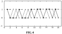
FIG. 4 is a structure diagram illustrating strong filter backtracking according to an embodiment of the disclosure. -
FIG. 5 is a structural diagram illustrating a strong filter compensation device according to an embodiment of the disclosure. - In order to understand the features and technical contents of the embodiments of the disclosure in more detail, the implementation of the embodiments of the disclosure will be elaborated herein below with reference to the drawings. The accompanying drawings are only used for illustration and reference, but to limit the embodiments of the disclosure.
- The technical solutions of the embodiments of the disclosure solve a strong filter effect through three steps: delay summation to solve the influence of a high-frequency noise; optimal path selection to find each correct path having a maximum probability; and compensation result judgment output where correct paths having the maximum probability within a period of time are taken into consideration to determine a final correct path.
-
FIG. 1 is a flowchart showing a strong filter compensation method according to an embodiment of the disclosure. As shown inFIG. 1 , the strong filter compensation method includes the steps as follows. - In
step 101, a high-frequency noise is filtered out by delay summation. - In the embodiment of the disclosure, received sampling point data is divided into two paths. One of the paths of sampling point data is delayed; and the delayed path of sampling point data and the other path of sampling point data are summated to filter out the high-frequency noise.
- Specifically, the delay summation refers to summation of adjacent sampling points to complete filter-out of a high-frequency noise. During specific implementation, it is supposed that a filter receives L sampling points Xi(0), Xi(1), ..., Xi(L-1), L ∈[0, ∞) at each clock period. The last data in L data received by a previous clock period is Xi-1(L-1), and outputs of the filter are f0, f1, ..., fL-1, so f0=Xi-1(L-1)+Xi(0), f1=Xi(0)+Xi(1), ..., fL-1=Xi(L-2)+Xi(L-1). In addition to data of the present clock period, the last sampling point of a previous clock period is needed for calculation of each clock period. In order to reduce an accumulation delay in a parallel operation, data of the last sampling point of the previous clock period is stored. Thus, a rate requirement can be met by adopting a structure as shown in
FIG. 2 . After power-up initialization or reset of a system, an initial value of the filter may be configurable on line, and may be solidified into a constant value such as the value of a first sampling point Xi-1(L-1)=0. - In the embodiment of the disclosure, after one of the paths of sampling point data is delayed, this path of sampling point data is multiplied by a weight parameter. Referring to
FIG. 3 , in the embodiment of the disclosure, the inputted sampling point data is X, X is divided into two paths, one of the paths is subjected to Z-1 delaying, and then the delayed sampling point data and the other path of directly-output sampling point data are summated to obtain S. A hardware implementation formula for a delay summation part is: Sk = (1 - α)●Xk + α●X k-1, where α is a configured parameter, a value range thereof is [0, 1], and a specific configured value is determined according to a channel situation. - In
step 102, a correct path is determined from one or more interference item paths. - In the embodiment of the disclosure, data subjected to delay summation is divided into four paths to calculate four measure results; the four measure results are divided into two groups and are compared and selected to determine a minimum measure result in each group and a path corresponding to the minimum measure result; the two minimum measure results are subtracted from each other, and an absolute value is calculated; and the absolute value is stored in a soft bit register group, and the paths corresponding to the minimum measure results are stored in a preceding state register group as correct paths.
- Specifically, referring to
FIG. 3 , after S is calculated by delay summation, four measures are calculated in four paths:


- β 00, β 01, β 10 and β 11 in the formula are acquired in two ways. In one way which is the same as the way of acquiring α, the parameter is acquired by configuration. In the other way, the parameter is acquired by calculating α. A calculation formula is as follows:


- W 00 and W 01 are compared and selected, a smaller output is W 0, and meanwhile, a selected output is serial number sel 0. If W 0 = W 00, sel 0 = 0, and otherwise, sel 0 =1. Similarly, W 10 and W 11 are compared and selected, and W 1 and sel 1 are outputted.
- δ in the above formula is used to calculate next Wij , an initial value of δ being 0. It is acquired in two ways. In one way, the parameter is acquired by configuration. In the other way, the parameter is acquired by calculation. A calculation formula is as follows:

- W 00 and W 10 are compared and selected, and a smaller output is D 0. W 01 and W 11 are compared and selected, and a smaller output is D 1. A result of abs(D 1 - D 0) is stored into a soft bit register group and used to output a soft bit. Here, abs(D 1 - D 0) represents calculation of an absolute value for (D 1 - D 0).
- In
step 103, the determined correct path for every data input during a pre-set period of time is comprehensively analyzed, the correct path which has the largest number of occurrences is taken as a final correct path, and data in the path is output. - In the embodiment of the disclosure, data in the preceding state register group is backtracked to determine a hard decision symbol; and when the hard decision symbol is identical to data in a corresponding soft bit register, a corresponding soft bit value is output, and when the hard decision symbol is different from the data in the corresponding soft bit register, a product of the hard decision symbol and a parameter K is output, wherein K is a configured parameter.
- Specifically, referring to
FIG. 3 , after M pieces of initial data are inputted, the preceding state register group will be backtracked every time one piece of data is inputted, and a hard decision symbol at corresponding time is outputted according to a backtracking state. Here, an output hard decision symbol corresponding to astate 0 is -, and an output hard decision symbol corresponding to astate 1 is +.FIG. 4 shows a situation where a preceding state register group with the length of 18 is backtracked. In the figure, a horizontal axis is time, and a longitudinal axis is a state value. Each solid dot in the figure corresponds to a register in the register group, and each dot has a line connected to a dot on the left of this dot, representing a preceding state stored in this register. - When backtracking is started, an initial state is determined according to a current δ value. If δ > 0, it is represented that W 0 > W 1, and backtracking is started from a register into which sel 0 is just stored. Otherwise, backtracking is started from a register into which sel 1 is just stored.
- In backtracking, a preceding state stored in a preceding state register is transferred to at one time. A solid line in
FIG. 4 marks a one-time backtracking process. The whole process undergoes (M+1) states. An output hard decision symbol corresponding to astate 0 is - and an output hard decision symbol corresponding to astate 1 is +. Only the leftmost hard decision symbol is outputted, and the following M hard decision symbols are abandoned. - If the hard decision symbol is the same as a correspondingly-stored soft bit symbol, a corresponding soft bit value is outputted. If the symbols are different, the output hard decision symbol is multiplied by a parameter K, K being a configured parameter.
-
FIG. 5 is a structural diagram illustrating a strong filter compensation device according to an embodiment of the disclosure. As shown inFIG. 5 , the device includes: - a
delay summation module 51, configured to filter out a high-frequency noise by delay summation; - an optimal
path selection module 52, configured to determine a correct path from one or more interference item paths; and - a compensation result
judgment output module 53, configured to comprehensively analyze the determined correct path for every data input during a pre-set period of time, take the correct path which has the largest number of occurrences as a final correct path, and output data in the path. - In the embodiment of the disclosure, the
delay summation module 51 includes: - a
separation sub-module 511, configured to divide received sampling point data into two paths; - a delaying sub-module 512, configured to delay one of the paths of sampling point data; and
- a summation sub-module 513, configured to summate the delayed path of sampling point data and the other path of sampling point data to filter out the high-frequency noise.
- In the embodiment of the disclosure, the delaying sub-module 512 is further configured to multiply, after one of the paths of sampling point data is delayed, this path of sampling point data by a weight parameter; and
the summation sub-module 513 is further configured to summate the path of sampling point data multiplied by the weight parameter and the other path of sampling point data. - In the embodiment of the disclosure, the optimal
path selection module 52 includes: - a
calculation sub-module 521, configured to divide data subjected to delay summation into four paths to calculate four measure results; - a comparison and
selection sub-module 522, configured to divide the four measure results into two groups to be compared and selected so as to determine a minimum measure result in each group and a path corresponding to the minimum measure result; - a
subtraction sub-module 523, configured to subtract the two minimum measure results from each other, and calculate an absolute value; and - a
storage sub-module 524, configured to store the absolute value in a soft bit register group, and store the paths corresponding to the minimum measure results, as correct paths, in a preceding state register group. - In the embodiment of the disclosure, the compensation result
judgment output module 53 includes: - a backtracking sub-module 531, configured to backtrack data in the preceding state register group to determine a hard decision symbol; and
- an
output sub-module 532, configured to output, when the hard decision symbol is identical to data in a corresponding soft bit register, a corresponding soft bit value, and output, when the hard decision symbol is different from the data in the corresponding soft bit register, a product of the hard decision symbol and a parameter K, wherein K is a configured parameter. - A person skilled in the art should understand that implementation functions of each unit and sub-units thereof in the strong filter compensation device as shown in
FIG. 5 may be understood with reference to relevant description for the aforementioned strong filter compensation method. Functions of each unit and sub-units thereof in the strong filter compensation device as shown inFIG. 5 may be implemented by a program running on a processor or may be implemented by a specific logic circuit. - In practical application, each unit module in the strong filter compensation device may be implemented by a Central Processing Unit (CPU), or a Digital Signal Processor (DSP), or a Field-Programmable Gate Array (FPGA).
- If being implemented in a form of software function module and sold or used as an independent product, the abovementioned service signaling tracking device in the embodiment of the disclosure may also be stored in a computer-readable storage medium. Based on such understanding, the technical solutions of the embodiments of the disclosure substantially or parts making contributions to the conventional art may be embodied in form of software product, and the computer software product is stored in a storage medium, including a plurality of instructions used to enable a computer device (which may be a personal computer, a server, network equipment or the like) to execute all or part of the method in each embodiment of the disclosure. The abovementioned storage medium includes: various media capable of storing program codes such as a U disk, a mobile hard disk, a Read-Only Memory (ROM), a magnetic disk or an optical disk. Thus, the embodiments of the disclosure are not limited to combination of any specific hardware and software.
- Correspondingly, the embodiments of the disclosure also provide a computer storage medium in which a computer program is stored, the computer program being used to execute the strong filter compensation methods in the embodiments of the disclosure.
- The technical solutions provided in the embodiments of the disclosure may be randomly combined without conflicts.
- In some embodiments provided by the disclosure, it should be understood that the disclosed method and intelligent equipment may be implemented in another manner. The equipment embodiment described above is only schematic, and for example, division of the units is only logic function division, and other division manners may be adopted during practical implementation. For example, multiple units or components may be combined or integrated into another system, or some characteristics may be neglected or not executed. In addition, coupling or direct coupling or communication connection between each displayed or discussed component may be indirect coupling or communication connection, implemented through some interfaces, of the equipment or the units, and may be electrical and mechanical or adopt other forms.
- The abovementioned units described as separate parts may or may not be physically separated, and parts displayed as units may or may not be physical units, and namely may be located in the same place, or may also be distributed to multiple network units. Part or all of the units may be selected to achieve the purpose of the solutions of the embodiment according to a practical requirement.
- In addition, each function unit in each embodiment of the disclosure may be integrated into a second processing unit, each unit may also exist independently, and two or more than two units may also be integrated into a unit. The abovementioned integrated unit may be implemented in a form of hardware, and may also be implemented in a form of hardware and software function unit.
- The above is only the specific implementation manners of the disclosure, but the scope of protection of the disclosure is not limited to this. As will occur to any person skilled in the art, the disclosure is susceptible to changes or replacements within the disclosed technical scope. These changes or replacements should fall within the scope of protection of the disclosure.
Claims (11)
- A strong filter compensation method, comprising:filtering out a high-frequency noise by delay summation;determining a correct path from one or more interference item paths for every data input; andcomprehensively analyzing the determined correct path for the every data input during a pre-set period of time, taking the correct path which has the largest number of occurrences as a final correct path, and outputting data in the path.
- The strong filter compensation method according to claim 1, wherein filtering out the high-frequency noise by the delay summation comprises:dividing received sampling point data into two paths;delaying one of the paths of sampling point data; andsummating the delayed path of sampling point data and the other path of sampling point data to filter out the high-frequency noise.
- The strong filter compensation method according to claim 2, further comprising:after one of the paths of sampling point data is delayed, multiplying the path of sampling point data by a weight parameter,wherein summating the delayed path of sampling point data and the other path of sampling point data comprises:summating the path of sampling point data multiplied by the weight parameter and the other path of sampling point data.
- The strong filter compensation method according to claim 1, wherein determining the correct path from one or more interference item paths comprises:dividing data subjected to the delay summation into four paths to calculate four measure results;dividing the four measure results into two groups to be compared and selected so as to determine a minimum measure result in each group and a path corresponding to the minimum measure result;subtracting the two minimum measure results from each other, and calculating an absolute value; andstoring the absolute value in a soft bit register group, and storing the paths corresponding to the minimum measure results, as correct paths, in a preceding state register group.
- The strong filter compensation method according to claim 4, wherein the step of comprehensively analyzing the determined correct path for the every data input during the pre-set period of time, taking the correct path which has the largest number of occurrences as the final correct path and outputting the data in the path comprises:backtracking data in the preceding state register group to determine a hard decision symbol; andwhen the hard decision symbol is identical to data in a corresponding soft bit register, outputting a corresponding soft bit value, and when the hard decision symbol is different from the data in the corresponding soft bit register, outputting a product of the hard decision symbol and a parameter K, K being a configured parameter.
- A strong filter compensation device, comprising:a delay summation module, configured to filter out a high-frequency noise by delay summation;an optimal path selection module, configured to determine a correct path from one or more interference item paths; anda compensation result judgment output module, configured to comprehensively analyze the determined correct path for every data input during a pre-set period of time, take the correct path which has the largest number of occurrences as a final correct path, and output data in the path.
- The strong filter compensation device according to claim 6, wherein the delay summation module comprises:a separation sub-module, configured to divide received sampling point data into two paths;a delaying sub-module, configured to delay one of the paths of sampling point data; anda summation sub-module, configured to summate the delayed path of sampling point data and the other path of sampling point data to filter out the high-frequency noise.
- The strong filter compensation device according to claim 7, wherein the delaying sub-module is further configured to multiply, after one of the paths of sampling point data is delayed, the path of sampling point data by a weight parameter; and
the summation sub-module is further configured to summate the path of sampling point data multiplied by the weight parameter and the other path of sampling point data. - The strong filter compensation device according to claim 6, wherein the optimal path selection module comprises:a calculation sub-module, configured to divide data subjected to the delay summation into four paths to calculate four measure results;a comparison and selection sub-module, configured to divide the four measure results into two groups to be compared and selected so as to determine a minimum measure result in each group and a path corresponding to the minimum measure result;a subtraction sub-module, configured to subtract the two minimum measure results from each other, and calculate an absolute value; anda storage sub-module, configured to store the absolute value in a soft bit register group, and store the paths corresponding to the minimum measure results, as correct paths, in a preceding state register group.
- The strong filter compensation device according to any one of claims 6 to 9, wherein the compensation result judgment output module comprises:a backtracking sub-module, configured to backtrack data in the preceding state register group to determine a hard decision symbol; andan output sub-module, configured to output, when the hard decision symbol is identical to data in a corresponding soft bit register, a corresponding soft bit value, and output, when the hard decision symbol is different from the data in the corresponding soft bit register, a product of the hard decision symbol and a parameter K, K being a configured parameter.
- A computer storage medium having computer-executable instructions stored, wherein the computer-executable instructions are configured to execute the strong filter compensation method according to any one of claims 1 to 5.
Applications Claiming Priority (2)
| Application Number | Priority Date | Filing Date | Title |
|---|---|---|---|
| CN201510304273.XA CN105024757B (en) | 2015-06-04 | 2015-06-04 | A kind of method and device of strong filtering compensation |
| PCT/CN2015/094349 WO2016192310A1 (en) | 2015-06-04 | 2015-11-11 | Strong filter compensation method and device, and computer storage medium |
Publications (2)
| Publication Number | Publication Date |
|---|---|
| EP3273622A1 true EP3273622A1 (en) | 2018-01-24 |
| EP3273622A4 EP3273622A4 (en) | 2018-04-25 |
Family
ID=54414502
Family Applications (1)
| Application Number | Title | Priority Date | Filing Date |
|---|---|---|---|
| EP15893955.3A Withdrawn EP3273622A4 (en) | 2015-06-04 | 2015-11-11 | Strong filter compensation method and device, and computer storage medium |
Country Status (6)
| Country | Link |
|---|---|
| US (1) | US10411803B2 (en) |
| EP (1) | EP3273622A4 (en) |
| JP (1) | JP6454797B2 (en) |
| KR (1) | KR102092084B1 (en) |
| CN (1) | CN105024757B (en) |
| WO (1) | WO2016192310A1 (en) |
Families Citing this family (2)
| Publication number | Priority date | Publication date | Assignee | Title |
|---|---|---|---|---|
| CN105024757B (en) * | 2015-06-04 | 2017-10-24 | 深圳市中兴微电子技术有限公司 | A kind of method and device of strong filtering compensation |
| CN107786477A (en) * | 2016-08-25 | 2018-03-09 | 深圳市中兴微电子技术有限公司 | A kind of data processing method and device |
Family Cites Families (14)
| Publication number | Priority date | Publication date | Assignee | Title |
|---|---|---|---|---|
| US7925079B1 (en) * | 1997-12-24 | 2011-04-12 | Mills Randell L | Method and system for pattern recognition and processing |
| EP1421700A4 (en) * | 2001-08-10 | 2008-04-23 | Adaptive Networks Inc | Digital equalization process and mechanism |
| WO2010057345A1 (en) * | 2008-11-24 | 2010-05-27 | 深圳市好易通科技有限公司 | Improved method for digitizing bit synchronization |
| WO2011030897A1 (en) * | 2009-09-14 | 2011-03-17 | 日本電信電話株式会社 | Band-variable communication method, band-variable communication apparatus, transmission band deciding apparatus, transmission band deciding method, node apparatus, communication path setting system, and communication path setting method |
| GB201002963D0 (en) | 2010-02-22 | 2010-04-07 | Uws Ventures Ltd | A communication system |
| CN102195903A (en) * | 2010-03-11 | 2011-09-21 | 南方医科大学 | Signal denoising method and amplifier |
| US8737496B2 (en) | 2010-04-01 | 2014-05-27 | Telefonaktiebolaget L M Ericsson (Publ) | Channel quality estimation for MLSE receiver |
| CN101827045B (en) | 2010-04-26 | 2013-06-05 | 华为技术有限公司 | Method for processing received signal and receiver |
| US8531980B2 (en) | 2010-06-29 | 2013-09-10 | Intel Corporation | Multi-channel communication station for communicating a multi-channel PPDU and methods of reducing collisions on secondary channels in multi-channel wireless networks |
| US8767531B2 (en) * | 2010-10-27 | 2014-07-01 | International Business Machines Corporation | Dynamic fault detection and repair in a data communications mechanism |
| CN102243880B (en) * | 2011-03-16 | 2015-02-18 | 中国科学院上海光学精密机械研究所 | Variable parameter self-adaptive PRML data receiver and data processing method thereof |
| US8891695B2 (en) | 2012-04-30 | 2014-11-18 | National Instruments Corporation | Maximizing the viterbi winning path metric to estimate carrier phase offset in continuous phase modulated signals |
| EP2782282A3 (en) | 2013-03-20 | 2018-04-04 | ZTE (USA) Inc. | Soft maximum likelihood sequence estimation in digital communication |
| CN105024757B (en) | 2015-06-04 | 2017-10-24 | 深圳市中兴微电子技术有限公司 | A kind of method and device of strong filtering compensation |
-
2015
- 2015-06-04 CN CN201510304273.XA patent/CN105024757B/en active Active
- 2015-11-11 JP JP2017554473A patent/JP6454797B2/en active Active
- 2015-11-11 KR KR1020177029716A patent/KR102092084B1/en active Active
- 2015-11-11 WO PCT/CN2015/094349 patent/WO2016192310A1/en not_active Ceased
- 2015-11-11 EP EP15893955.3A patent/EP3273622A4/en not_active Withdrawn
- 2015-11-11 US US15/564,924 patent/US10411803B2/en active Active
Also Published As
| Publication number | Publication date |
|---|---|
| JP6454797B2 (en) | 2019-01-16 |
| US10411803B2 (en) | 2019-09-10 |
| EP3273622A4 (en) | 2018-04-25 |
| US20180097566A1 (en) | 2018-04-05 |
| KR102092084B1 (en) | 2020-03-24 |
| WO2016192310A1 (en) | 2016-12-08 |
| JP2018513645A (en) | 2018-05-24 |
| CN105024757B (en) | 2017-10-24 |
| CN105024757A (en) | 2015-11-04 |
| KR20170129210A (en) | 2017-11-24 |
Similar Documents
| Publication | Publication Date | Title |
|---|---|---|
| KR102240293B1 (en) | System and method for maintaining high speed communication | |
| JP6149150B2 (en) | Timestamp correction in skewed multilane communication links | |
| US12126375B2 (en) | Automatic trend identification and anomaly detection in optical channel monitoring spectrum | |
| US10411803B2 (en) | Strong filter compensation method and device, and computer storage medium | |
| US11936505B2 (en) | Decision feedback equalization with efficient burst error correction | |
| CN105790792B (en) | A kind of subscriber line far-end crosstalk cancellation vector calculation method and device | |
| WO2023138516A1 (en) | Systems and methods for optical filter fault localization | |
| GB2532284A (en) | Method to reduce dynamic clock skew and/or slew in an electronic circuit | |
| CN115660957A (en) | Resampling method, device, equipment and medium for waveform data | |
| KR20130113276A (en) | PCI Express deskew device and method thereof | |
| JP2012244537A (en) | Data recovery method and data recovery device | |
| CN104467939A (en) | Method and device for optimizing receiving of multiple antennas | |
| WO2016192321A1 (en) | Phase ambiguity correction method and device, and computer storage medium | |
| CN118337629A (en) | Data transmission system, method, device, equipment and medium | |
| US20090245395A1 (en) | Transmission control apparatus and transmission control method | |
| US9641386B2 (en) | Networking device port multiplexing | |
| WO2016206225A1 (en) | Strong filtering cancellation method and apparatus, and computer storage medium | |
| CN111600784B (en) | Data processing method, network equipment, main control board and logic chip | |
| CN121547075B (en) | Methods, systems, and electronic devices for optimizing synchronous data crosstalk effects | |
| EP4582327A1 (en) | Method and apparatus for switching signal mode, and device and storage medium | |
| CN107925513B (en) | Error monitoring apparatus, method and recording medium | |
| ITMI20102436A1 (en) | CROSS-CORRELATION RECEIVER | |
| CN111901178B (en) | Risk pre-judging method, device and equipment for network flow direction | |
| EP4213437B1 (en) | Clock and data recovery system and operating method thereof | |
| CN120825461B (en) | A Method and System for Parallel Processing and Buffer Optimization of High-Speed Fiber Optic Data Streams Based on FPGA |
Legal Events
| Date | Code | Title | Description |
|---|---|---|---|
| PUAI | Public reference made under article 153(3) epc to a published international application that has entered the european phase |
Free format text: ORIGINAL CODE: 0009012 |
|
| 17P | Request for examination filed |
Effective date: 20171018 |
|
| AK | Designated contracting states |
Kind code of ref document: A1 Designated state(s): AL AT BE BG CH CY CZ DE DK EE ES FI FR GB GR HR HU IE IS IT LI LT LU LV MC MK MT NL NO PL PT RO RS SE SI SK SM TR |
|
| AX | Request for extension of the european patent |
Extension state: BA ME |
|
| A4 | Supplementary search report drawn up and despatched |
Effective date: 20180322 |
|
| RIC1 | Information provided on ipc code assigned before grant |
Ipc: H04J 14/02 20060101ALI20180316BHEP Ipc: H04B 10/2507 20130101AFI20180316BHEP |
|
| DAV | Request for validation of the european patent (deleted) | ||
| DAX | Request for extension of the european patent (deleted) | ||
| STAA | Information on the status of an ep patent application or granted ep patent |
Free format text: STATUS: THE APPLICATION IS DEEMED TO BE WITHDRAWN |
|
| 18D | Application deemed to be withdrawn |
Effective date: 20181023 |