EP3273475A2 - Fan-out package structure - Google Patents
Fan-out package structure Download PDFInfo
- Publication number
- EP3273475A2 EP3273475A2 EP17173260.5A EP17173260A EP3273475A2 EP 3273475 A2 EP3273475 A2 EP 3273475A2 EP 17173260 A EP17173260 A EP 17173260A EP 3273475 A2 EP3273475 A2 EP 3273475A2
- Authority
- EP
- European Patent Office
- Prior art keywords
- layer
- semiconductor package
- package structure
- rdl
- conductive layer
- Prior art date
- Legal status (The legal status is an assumption and is not a legal conclusion. Google has not performed a legal analysis and makes no representation as to the accuracy of the status listed.)
- Granted
Links
Images



Classifications
-
- H—ELECTRICITY
- H10—SEMICONDUCTOR DEVICES; ELECTRIC SOLID-STATE DEVICES NOT OTHERWISE PROVIDED FOR
- H10W—GENERIC PACKAGES, INTERCONNECTIONS, CONNECTORS OR OTHER CONSTRUCTIONAL DETAILS OF DEVICES COVERED BY CLASS H10
- H10W70/00—Package substrates; Interposers; Redistribution layers [RDL]
- H10W70/60—Insulating or insulated package substrates; Interposers; Redistribution layers
- H10W70/62—Insulating or insulated package substrates; Interposers; Redistribution layers characterised by their interconnections
- H10W70/65—Shapes or dispositions of interconnections
-
- H—ELECTRICITY
- H10—SEMICONDUCTOR DEVICES; ELECTRIC SOLID-STATE DEVICES NOT OTHERWISE PROVIDED FOR
- H10W—GENERIC PACKAGES, INTERCONNECTIONS, CONNECTORS OR OTHER CONSTRUCTIONAL DETAILS OF DEVICES COVERED BY CLASS H10
- H10W42/00—Arrangements for protection of devices
- H10W42/20—Arrangements for protection of devices protecting against electromagnetic or particle radiation, e.g. light, X-rays, gamma-rays or electrons
-
- H—ELECTRICITY
- H10—SEMICONDUCTOR DEVICES; ELECTRIC SOLID-STATE DEVICES NOT OTHERWISE PROVIDED FOR
- H10W—GENERIC PACKAGES, INTERCONNECTIONS, CONNECTORS OR OTHER CONSTRUCTIONAL DETAILS OF DEVICES COVERED BY CLASS H10
- H10W44/00—Electrical arrangements for controlling or matching impedance
- H10W44/20—Electrical arrangements for controlling or matching impedance at high-frequency [HF] or radio frequency [RF]
-
- H—ELECTRICITY
- H10—SEMICONDUCTOR DEVICES; ELECTRIC SOLID-STATE DEVICES NOT OTHERWISE PROVIDED FOR
- H10W—GENERIC PACKAGES, INTERCONNECTIONS, CONNECTORS OR OTHER CONSTRUCTIONAL DETAILS OF DEVICES COVERED BY CLASS H10
- H10W70/00—Package substrates; Interposers; Redistribution layers [RDL]
- H10W70/60—Insulating or insulated package substrates; Interposers; Redistribution layers
-
- H—ELECTRICITY
- H10—SEMICONDUCTOR DEVICES; ELECTRIC SOLID-STATE DEVICES NOT OTHERWISE PROVIDED FOR
- H10W—GENERIC PACKAGES, INTERCONNECTIONS, CONNECTORS OR OTHER CONSTRUCTIONAL DETAILS OF DEVICES COVERED BY CLASS H10
- H10W70/00—Package substrates; Interposers; Redistribution layers [RDL]
- H10W70/60—Insulating or insulated package substrates; Interposers; Redistribution layers
- H10W70/611—Insulating or insulated package substrates; Interposers; Redistribution layers for connecting multiple chips together
-
- H—ELECTRICITY
- H10—SEMICONDUCTOR DEVICES; ELECTRIC SOLID-STATE DEVICES NOT OTHERWISE PROVIDED FOR
- H10W—GENERIC PACKAGES, INTERCONNECTIONS, CONNECTORS OR OTHER CONSTRUCTIONAL DETAILS OF DEVICES COVERED BY CLASS H10
- H10W74/00—Encapsulations, e.g. protective coatings
- H10W74/10—Encapsulations, e.g. protective coatings characterised by their shape or disposition
- H10W74/131—Encapsulations, e.g. protective coatings characterised by their shape or disposition the semiconductor body being only partially enclosed
- H10W74/141—Encapsulations, e.g. protective coatings characterised by their shape or disposition the semiconductor body being only partially enclosed the encapsulations being on at least the sidewalls of the semiconductor body
-
- H—ELECTRICITY
- H10—SEMICONDUCTOR DEVICES; ELECTRIC SOLID-STATE DEVICES NOT OTHERWISE PROVIDED FOR
- H10W—GENERIC PACKAGES, INTERCONNECTIONS, CONNECTORS OR OTHER CONSTRUCTIONAL DETAILS OF DEVICES COVERED BY CLASS H10
- H10W90/00—Package configurations
- H10W90/701—Package configurations characterised by the relative positions of pads or connectors relative to package parts
-
- H—ELECTRICITY
- H10—SEMICONDUCTOR DEVICES; ELECTRIC SOLID-STATE DEVICES NOT OTHERWISE PROVIDED FOR
- H10W—GENERIC PACKAGES, INTERCONNECTIONS, CONNECTORS OR OTHER CONSTRUCTIONAL DETAILS OF DEVICES COVERED BY CLASS H10
- H10W44/00—Electrical arrangements for controlling or matching impedance
- H10W44/20—Electrical arrangements for controlling or matching impedance at high-frequency [HF] or radio frequency [RF]
- H10W44/241—Electrical arrangements for controlling or matching impedance at high-frequency [HF] or radio frequency [RF] for passive devices or passive elements
- H10W44/248—Electrical arrangements for controlling or matching impedance at high-frequency [HF] or radio frequency [RF] for passive devices or passive elements for antennas
-
- H—ELECTRICITY
- H10—SEMICONDUCTOR DEVICES; ELECTRIC SOLID-STATE DEVICES NOT OTHERWISE PROVIDED FOR
- H10W—GENERIC PACKAGES, INTERCONNECTIONS, CONNECTORS OR OTHER CONSTRUCTIONAL DETAILS OF DEVICES COVERED BY CLASS H10
- H10W70/00—Package substrates; Interposers; Redistribution layers [RDL]
- H10W70/60—Insulating or insulated package substrates; Interposers; Redistribution layers
- H10W70/611—Insulating or insulated package substrates; Interposers; Redistribution layers for connecting multiple chips together
- H10W70/614—Insulating or insulated package substrates; Interposers; Redistribution layers for connecting multiple chips together the multiple chips being integrally enclosed
-
- H—ELECTRICITY
- H10—SEMICONDUCTOR DEVICES; ELECTRIC SOLID-STATE DEVICES NOT OTHERWISE PROVIDED FOR
- H10W—GENERIC PACKAGES, INTERCONNECTIONS, CONNECTORS OR OTHER CONSTRUCTIONAL DETAILS OF DEVICES COVERED BY CLASS H10
- H10W70/00—Package substrates; Interposers; Redistribution layers [RDL]
- H10W70/60—Insulating or insulated package substrates; Interposers; Redistribution layers
- H10W70/62—Insulating or insulated package substrates; Interposers; Redistribution layers characterised by their interconnections
- H10W70/63—Vias, e.g. via plugs
-
- H—ELECTRICITY
- H10—SEMICONDUCTOR DEVICES; ELECTRIC SOLID-STATE DEVICES NOT OTHERWISE PROVIDED FOR
- H10W—GENERIC PACKAGES, INTERCONNECTIONS, CONNECTORS OR OTHER CONSTRUCTIONAL DETAILS OF DEVICES COVERED BY CLASS H10
- H10W70/00—Package substrates; Interposers; Redistribution layers [RDL]
- H10W70/60—Insulating or insulated package substrates; Interposers; Redistribution layers
- H10W70/67—Insulating or insulated package substrates; Interposers; Redistribution layers characterised by their insulating layers or insulating parts
- H10W70/68—Shapes or dispositions thereof
- H10W70/685—Shapes or dispositions thereof comprising multiple insulating layers
-
- H—ELECTRICITY
- H10—SEMICONDUCTOR DEVICES; ELECTRIC SOLID-STATE DEVICES NOT OTHERWISE PROVIDED FOR
- H10W—GENERIC PACKAGES, INTERCONNECTIONS, CONNECTORS OR OTHER CONSTRUCTIONAL DETAILS OF DEVICES COVERED BY CLASS H10
- H10W72/00—Interconnections or connectors in packages
- H10W72/071—Connecting or disconnecting
- H10W72/072—Connecting or disconnecting of bump connectors
-
- H—ELECTRICITY
- H10—SEMICONDUCTOR DEVICES; ELECTRIC SOLID-STATE DEVICES NOT OTHERWISE PROVIDED FOR
- H10W—GENERIC PACKAGES, INTERCONNECTIONS, CONNECTORS OR OTHER CONSTRUCTIONAL DETAILS OF DEVICES COVERED BY CLASS H10
- H10W72/00—Interconnections or connectors in packages
- H10W72/071—Connecting or disconnecting
- H10W72/073—Connecting or disconnecting of die-attach connectors
-
- H—ELECTRICITY
- H10—SEMICONDUCTOR DEVICES; ELECTRIC SOLID-STATE DEVICES NOT OTHERWISE PROVIDED FOR
- H10W—GENERIC PACKAGES, INTERCONNECTIONS, CONNECTORS OR OTHER CONSTRUCTIONAL DETAILS OF DEVICES COVERED BY CLASS H10
- H10W72/00—Interconnections or connectors in packages
- H10W72/20—Bump connectors, e.g. solder bumps or copper pillars; Dummy bumps; Thermal bumps
- H10W72/241—Dispositions, e.g. layouts
-
- H—ELECTRICITY
- H10—SEMICONDUCTOR DEVICES; ELECTRIC SOLID-STATE DEVICES NOT OTHERWISE PROVIDED FOR
- H10W—GENERIC PACKAGES, INTERCONNECTIONS, CONNECTORS OR OTHER CONSTRUCTIONAL DETAILS OF DEVICES COVERED BY CLASS H10
- H10W72/00—Interconnections or connectors in packages
- H10W72/90—Bond pads, in general
- H10W72/941—Dispositions of bond pads
- H10W72/9413—Dispositions of bond pads on encapsulations
-
- H—ELECTRICITY
- H10—SEMICONDUCTOR DEVICES; ELECTRIC SOLID-STATE DEVICES NOT OTHERWISE PROVIDED FOR
- H10W—GENERIC PACKAGES, INTERCONNECTIONS, CONNECTORS OR OTHER CONSTRUCTIONAL DETAILS OF DEVICES COVERED BY CLASS H10
- H10W74/00—Encapsulations, e.g. protective coatings
- H10W74/10—Encapsulations, e.g. protective coatings characterised by their shape or disposition
- H10W74/111—Encapsulations, e.g. protective coatings characterised by their shape or disposition the semiconductor body being completely enclosed
- H10W74/114—Encapsulations, e.g. protective coatings characterised by their shape or disposition the semiconductor body being completely enclosed by a substrate and the encapsulations
- H10W74/117—Encapsulations, e.g. protective coatings characterised by their shape or disposition the semiconductor body being completely enclosed by a substrate and the encapsulations the substrate having spherical bumps for external connection
-
- H—ELECTRICITY
- H10—SEMICONDUCTOR DEVICES; ELECTRIC SOLID-STATE DEVICES NOT OTHERWISE PROVIDED FOR
- H10W—GENERIC PACKAGES, INTERCONNECTIONS, CONNECTORS OR OTHER CONSTRUCTIONAL DETAILS OF DEVICES COVERED BY CLASS H10
- H10W74/00—Encapsulations, e.g. protective coatings
- H10W74/10—Encapsulations, e.g. protective coatings characterised by their shape or disposition
- H10W74/15—Encapsulations, e.g. protective coatings characterised by their shape or disposition on active surfaces of flip-chip devices, e.g. underfills
-
- H—ELECTRICITY
- H10—SEMICONDUCTOR DEVICES; ELECTRIC SOLID-STATE DEVICES NOT OTHERWISE PROVIDED FOR
- H10W—GENERIC PACKAGES, INTERCONNECTIONS, CONNECTORS OR OTHER CONSTRUCTIONAL DETAILS OF DEVICES COVERED BY CLASS H10
- H10W90/00—Package configurations
-
- H—ELECTRICITY
- H10—SEMICONDUCTOR DEVICES; ELECTRIC SOLID-STATE DEVICES NOT OTHERWISE PROVIDED FOR
- H10W—GENERIC PACKAGES, INTERCONNECTIONS, CONNECTORS OR OTHER CONSTRUCTIONAL DETAILS OF DEVICES COVERED BY CLASS H10
- H10W90/00—Package configurations
- H10W90/10—Configurations of laterally-adjacent chips
-
- H—ELECTRICITY
- H10—SEMICONDUCTOR DEVICES; ELECTRIC SOLID-STATE DEVICES NOT OTHERWISE PROVIDED FOR
- H10W—GENERIC PACKAGES, INTERCONNECTIONS, CONNECTORS OR OTHER CONSTRUCTIONAL DETAILS OF DEVICES COVERED BY CLASS H10
- H10W90/00—Package configurations
- H10W90/701—Package configurations characterised by the relative positions of pads or connectors relative to package parts
- H10W90/721—Package configurations characterised by the relative positions of pads or connectors relative to package parts of bump connectors
- H10W90/724—Package configurations characterised by the relative positions of pads or connectors relative to package parts of bump connectors between a chip and a stacked insulating package substrate, interposer or RDL
-
- H—ELECTRICITY
- H10—SEMICONDUCTOR DEVICES; ELECTRIC SOLID-STATE DEVICES NOT OTHERWISE PROVIDED FOR
- H10W—GENERIC PACKAGES, INTERCONNECTIONS, CONNECTORS OR OTHER CONSTRUCTIONAL DETAILS OF DEVICES COVERED BY CLASS H10
- H10W90/00—Package configurations
- H10W90/701—Package configurations characterised by the relative positions of pads or connectors relative to package parts
- H10W90/721—Package configurations characterised by the relative positions of pads or connectors relative to package parts of bump connectors
- H10W90/729—Package configurations characterised by the relative positions of pads or connectors relative to package parts of bump connectors between a chip and a laterally-adjacent discrete passive device
-
- H—ELECTRICITY
- H10—SEMICONDUCTOR DEVICES; ELECTRIC SOLID-STATE DEVICES NOT OTHERWISE PROVIDED FOR
- H10W—GENERIC PACKAGES, INTERCONNECTIONS, CONNECTORS OR OTHER CONSTRUCTIONAL DETAILS OF DEVICES COVERED BY CLASS H10
- H10W90/00—Package configurations
- H10W90/701—Package configurations characterised by the relative positions of pads or connectors relative to package parts
- H10W90/731—Package configurations characterised by the relative positions of pads or connectors relative to package parts of die-attach connectors
- H10W90/734—Package configurations characterised by the relative positions of pads or connectors relative to package parts of die-attach connectors between a chip and a stacked insulating package substrate, interposer or RDL
Definitions
- the present invention relates to a semiconductor package structure, and in particular to a fan-out package structure.
- RF radio frequency
- SiP system-in-package
- a discrete antenna component is individually encapsulated or mounted on a printed circuit board (PCB) or package.
- PCB printed circuit board
- semiconductor dies, components, and passive devices are arranged side-by-side. However, it is required to provide additional area for the antenna component mounted thereon. Moreover, it is required to provide a large area for arrangement of these semiconductor dies, components, and passive devices.
- the SiP structure As a result, it is difficult to reduce the footprint (i.e., plane size) of the SiP structure. Additionally, the reduction of the total height of the SiP structure is also difficult due to the configuration including the antenna component encapsulated or mounted on the package and the underlying semiconductor dies, components, and passive devices with a side-by-side arrangement.
- An exemplary embodiment of a semiconductor package structure including a redistribution layer (RDL) structure having a first surface and a second surface opposite thereto is provided.
- the RDL structure includes an inter-metal dielectric (IMD) layer and a first conductive layer disposed at a first layer-level of the IMD layer.
- IMD inter-metal dielectric
- a molding compound covers the first surface of the RDL structure.
- a first semiconductor die is disposed over the second surface of the RDL structure and electrically coupled to the RDL structure.
- a plurality of bump structures is disposed over the second surface of the RDL structure and electrically coupled to the RDL structure.
- a semiconductor package structure including an RDL structure having a first surface and a second surface opposite thereto.
- the RDL structure includes an IMD layer, a first conductive layer disposed at a first layer-level of the IMD layer, and a second conductive layer disposed at a second layer-level below the first layer-level of the IMD layer.
- a molding compound covers the first surface of the RDL structure.
- a first semiconductor die is disposed over the second surface of the RDL structure and electrically coupled to the RDL structure.
- a plurality of bump structures is disposed over the second surface of the RDL structure and electrically coupled to the RDL structure.
- a semiconductor package structure including an RDL structure having a first surface and a second surface opposite thereto.
- the RDL structure includes an IMD layer, a first conductive layer disposed at a first layer-level of the IMD layer, a second conductive layer disposed at a second layer-level below the first layer-level of the IMD layer, and a third conductive layer disposed at a third layer-level below the second layer-level of the IMD layer.
- a molding compound covers the first surface of the RDL structure.
- a first semiconductor die is disposed over the second surface of the RDL structure and electrically coupled to the RDL structure.
- a plurality of bump structures is disposed over the second surface of the RDL structure and electrically coupled to the RDL structure.
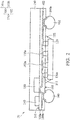
- FIG. 1 is a cross-sectional view of a semiconductor package structure 10 in accordance with some embodiments of the disclosure.
- the semiconductor package structure 10 is a wafer-level semiconductor package structure, for example, a flip-chip semiconductor package structure.
- the semiconductor package structure 10 may be a wafer-level semiconductor package structure that may be mounted on a base (not shown).
- the semiconductor package structure 10 may be a system-on-chip (SOC) package structure.
- the base may include a printed circuit board (PCB) and may be formed of polypropylene (PP).
- the base may include a package substrate.
- the semiconductor package structure 10 is mounted on the base by a bonding process.
- the semiconductor package structure 10 includes bump structures 160 (such as conductive ball structures, conductive pillar structure, or conductive paste structures) that is mounted on and electrically coupled to the base by the bonding process.
- the semiconductor package structure 10 includes an RDL structure 110 and the bump structures 160 electrically coupled thereto.
- the RDL structure 110 which is also referred to as a fan-out structure, has a first surface 101 and a second surface 103 opposite thereto.
- the RDL structure 110 includes one or more conductive layers disposed in an IMD layer 100. For example, a single first conductive layer 102 is disposed at a first layer-level of the IMD layer 100.
- the IMD layer 100 may include first and second sub-dielectric layers 100a and 100b successively stacked from the first surface 101 of the RDL structure 110 toward the second surface 103 of the RDL structure 110, such that the first conductive layer 102 is positioned between the first and second sub-dielectric layers 100a and 100b.
- the IMD layer 100 may be formed of organic materials, which include a polymer base material, non-organic materials, which include silicon nitride (SiN x ), silicon oxide (SiO x ), graphene, or the like.
- the first and second sub-dielectric layers 100a and 100b are made of a polymer base material.
- the bump structures 160 are disposed over the second surface 103 of the RDL structure 110 and electrically coupled to the RDL structure 110.
- pad portions of the first conductive layer 102 are exposed to openings of the second sub-dielectric layer 100b and connected to the corresponding bump structures 160 through the corresponding under bump metallization (UBM) layers 160a.
- UBM under bump metallization
- the semiconductor package structure 10 further includes a first semiconductor die 120, such as an SOC die.
- the first semiconductor die 120 is disposed over the second surface 103 of the RDL structure 110 and the first conductive layer 102 is electrically coupled to the first semiconductor die 120.
- the first semiconductor die 120 is fabricated by flip-chip technology.
- Bump structures 120a of the first semiconductor die 120 are electrically connected to the circuitry (not shown) of the first semiconductor die 120.
- the bump structures 120a of the first semiconductor die 120 are surrounded by an underfill layer 122 that is interposed between the second surface 103 of the RDL structure 110 and the first semiconductor die 120.
- the bump structures 120a of the first semiconductor die 120 are in contact with corresponding conductive structures 111 (e.g., conductive bumps, posts or solder pastes), so that the first semiconductor die 120 is electrically coupled to the first conductive layers 102 through conductive structures 111.
- conductive structures 111 e.g., conductive bumps, posts or solder pastes
- the semiconductor package structure 10 further includes one or more second semiconductor dies 130 and one or more electronic components 140 disposed on the second surface 103 of the RDL structure 110.
- the semiconductor package structure 10 further includes one or more second semiconductor dies 130 and one or more electronic components 140 disposed on the second surface 103 of the RDL structure 110.
- the semiconductor package structure 10 further includes one or more second semiconductor dies 130 and one or more electronic components 140 disposed on the second surface 103 of the RDL structure 110.
- a second semiconductor die 130 and three electronic components 140 are depicted.
- the number of semiconductor dies or electronic components integrated in the semiconductor package structure 10 is not limited to that disclosed in the embodiment.
- the second semiconductor die 130 and the electronic components 140 are arranged side-by-side and electrically coupled to the RDL structure 110 through the first conductive layer 102.
- the second semiconductor die 130 is a radio frequency front-end component, an integrated passive device (IPD)), or a combination thereof.
- the second semiconductor die 130 may include a microcontroller (MCU), a microprocessor (MPU), a random access memory (RAM), a power management integrated circuit (PMIC), a flash memory, or a global positioning system (GPS) device, or any combination thereof.
- the electronic component 140 is a passive device, such as a capacitor, an inductor, a resistor, or a combination thereof.
- the semiconductor package structure 10 further includes a molding compound 150 covering the first surface 101 of the RDL structure 110.
- the second semiconductor die 130 and the electronic components 140 are disposed within the molding compound 150.
- the molding compound 150 may be formed of an epoxy, a resin, a moldable polymer, or the like. The molding compound 150 may be applied while substantially liquid, and then may be cured through a chemical reaction, such as in an epoxy or resin.
- the molding compound 150 may be an ultraviolet (UV) or thermally cured polymer applied as a gel or malleable solid capable of being disposed around the second semiconductor die 130 and the electronic components 140, and then may be cured through a UV or thermal curing process. The molding compound 150 may be cured with a mold (not shown).
- the bump structures 160 are separated from the molding compound 150 through the RDL structure 110. In other words, the bump structures 160 are free from contact with the molding compound 150.
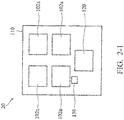
- FIG. 2 is a cross-sectional view of an exemplary semiconductor package structure 20 in accordance with some embodiments of the disclosure and FIG. 2-1 is a plan view of an arrangement of an antenna pattern in the semiconductor package structure 20 shown in FIG. 2 .
- Descriptions of elements of the embodiments hereinafter that are the same as or similar to those previously described with reference to FIG. 1 are omitted for brevity.
- the semiconductor package structure 20 is similar to the semiconductor package structure 10 shown in FIG. 1 , except that the first conductive layer 102 has one or more antenna patterns 102a.
- the first conductive layer 102 with antenna patterns 102a enables wireless communication for the semiconductor package structure 20.
- a second semiconductor die 130 and an electronic component 140 are depicted.
- the number of semiconductor dies or electronic components integrated in the semiconductor package structure 20 is not limited to that disclosed in the embodiment.
- the first conductive layer 102 has four antenna patterns 102a that are arranged in an array as seen from a top view.
- the antenna patterns 102a of first conductive layer 102 are laterally spaced apart from the first semiconductor die 120, the second semiconductor die 130, and the electronic components 140 (not shown), as viewed from a top-view aspect.
- each of the antenna patterns 102a of the first conductive layer 102 is rectangular, as viewed from a top-view aspect.
- the antenna patterns 102a of the first conductive layer 102 can be used for various shapes. Also, it should be noted that the number of antenna patterns integrated in the semiconductor package structure 20 and the arrangement of the antenna patterns are not limited to those disclosed in the embodiment.
- the antenna component is integrated in the RDL structure 110, the overall height of the semiconductor package structure 20 can be reduced.
- the first conductive layer 102 semiconductor package structure 20 may have a ground shielding pattern (not shown) instead of the antenna patterns.
- the antenna patterns may be mounted on the semiconductor package structure 20.
- the ground shielding component may reduce the effect of electrical noise on the signals, and to reduce the electromagnetic radiation that can interfere with other devices.
- FIG. 3 is a cross-sectional view of an exemplary semiconductor package structure 30 in accordance with some embodiments of the disclosure. Descriptions of elements of the embodiments hereinafter that are the same as or similar to those previously described with reference to FIG. 1 or 2 are omitted for brevity.
- the semiconductor package structure 30 is similar to the semiconductor package structure 20 shown in FIG. 2 , except the configuration of the RDL structure 110.
- the RDL structure 110 includes two conductive layers disposed at different layer-levels of the IMD layer 100.
- a first conductive layer 102 is disposed at a first layer-level of the IMD layer 100 and a second conductive layer 104 is disposed at a second layer-level below the first layer-level of the IMD layer 100.
- the IMD layer 100 may include first, second, and third sub-dielectric layers 100a, 100b, and 100c successively stacked from the first surface 101 of the RDL structure 110 toward the second surface 103 of the RDL structure 110, such that the first conductive layer 102 is positioned between the first and second sub-dielectric layers 100a and 100b.
- the second conductive layer 104 is positioned between the second and third sub-dielectric layers 100b and 100c.
- pad portions of the second conductive layer 104 are exposed to openings of the third sub-dielectric layer 100c and connected to the corresponding bump structures 160 through the corresponding UBM layers 160a.
- the antenna patterns 102a of the first conductive layer 102 may have a shape and an arrangement that are the same as or different than those shown in FIG. 2-1 . It should be understood that those of ordinary skill in the art know that various shapes can be used for the antenna patterns 102a of the first conductive layer 102. Also, it should be noted that the number of antenna patterns integrated in the semiconductor package structure 30 and the arrangement of the antenna patterns are not limited to those disclosed in the embodiment.
- the first conductive layer 102 in the semiconductor package structure 30 may have a ground shielding pattern (not shown) instead of the antenna patterns.
- the antenna patterns may be mounted on the semiconductor package structure 30.
- FIG. 4 is a cross-sectional view of an exemplary semiconductor package structure 40 in accordance with some embodiments of the disclosure and FIG. 4-1 is a plan view of an arrangement of an antenna pattern and a ground shielding pattern in the semiconductor package structure 40 shown in FIG. 4 .
- Descriptions of elements of the embodiments hereinafter that are the same as or similar to those previously described with reference to FIG. 3 are omitted for brevity.
- the semiconductor package structure 40 is similar to the semiconductor package structure 30 shown in FIG. 3 , except the configuration of the RDL structure 110.
- the first conductive layer 102 has one or more antenna patterns 102a and the second conductive layer 104 has a ground shielding pattern 104a that is arranged underneath the antenna patterns 102a.
- the second conductive layer 104 with the ground shielding pattern 104a may reduce electrical noise between the antenna patterns 102a and the first semiconductor die 120, and reduce the electromagnetic radiation that can interfere with other devices.
- the RDL structure 110 includes three conductive layers disposed at different layer-levels of the IMD layer 100.
- a first conductive layer 102 is disposed at a first layer-level of the IMD layer 100
- a second conductive layer 104 is disposed at a second layer-level below the first layer-level of the IMD layer 100
- a third conductive layer 106 disposed at a third layer-level below the second layer-level of the IMD layer 100.
- the IMD layer 100 may include first, second, third, and fourth sub-dielectric layers 100a, 100b, 100c, and 100d successively stacked from the first surface 101 of the RDL structure 110 toward the second surface 103 of the RDL structure 110, such that the first conductive layer 102 is positioned between the first and second sub-dielectric layers 100a and 100b.
- the second conductive layer 104 is positioned between the second and third sub-dielectric layers 100b and 100c.
- the third conductive layer 106 is positioned between the third and fourth sub-dielectric layers 100c and 100d.
- pad portions of the third conductive layer 106 are exposed to openings of the fourth sub-dielectric layer 100d and connected to the corresponding bump structures 160 through the corresponding UBM layers 160a.
- the first conductive layer 102 has four antenna patterns 102a that are arranged in an array as seen from a top view.
- the surface of the first semiconductor die 120 is entirely covered by the ground shielding pattern 104a, as viewed from a top-view aspect.
- the antenna patterns 102a of first conductive layer 102 are laterally spaced apart from the second semiconductor die 130 and the electronic components 140 (not shown), as viewed from a top-view aspect.
- Each of the antenna patterns 102a of the first conductive layer 102 is rectangular, as viewed from a top-view aspect.
- the number of antenna patterns integrated in the semiconductor package structure 40 and the arrangement of the antenna patterns are not limited to those disclosed in the embodiment.
- the antenna component is integrated in the RDL structure 110
- the overall height of the semiconductor package structure 40 can be reduced.
- the ground shielding component is integrated in the RDL structure 110, the electrical noise between the antenna patterns 102a and the first semiconductor die 120 can be prevented by the ground shielding component.
- the first semiconductor die 120 can be arranged underneath the antenna component, as shown in FIG. 4-1 , thereby reducing the footprint (i.e., plane size) of the semiconductor package structure 40.
- FIG. 5 is a cross-sectional view of an exemplary semiconductor package structure 50 in accordance with some embodiments of the disclosure and FIG. 5-1 is a plan view of an arrangement of an antenna pattern and a ground shielding pattern in the semiconductor package structure 50 shown in FIG. 5 .
- the semiconductor package structure 50 is similar to the semiconductor package structure 40 shown in FIG. 4 . Unlike the semiconductor package structure 40, the second semiconductor die 130 and electronic components 140 (as shown in FIG. 4 ) are not disposed in the semiconductor package structure 50.
- the antenna patterns 102a of the first conductive layer 102 may have a shape and an arrangement that are the same as those shown in FIG. 4-1 . Moreover, the arrangement of the ground shielding pattern 104a and the first semiconductor die 120 is the same as that shown in FIG. 4-1 . However, it should be understood that those of ordinary skill in the art know that various shapes can be used for the antenna patterns 102a of the first conductive layer 102. Also, it should be noted that the number of antenna patterns integrated in the semiconductor package structure 50 and the arrangement of the antenna patterns are not limited to those disclosed in the embodiment
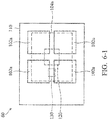
- FIG. 6 is a cross-sectional view of an exemplary semiconductor package structure 60 in accordance with some embodiments of the disclosure and FIG. 6-1 is a plan view of an arrangement of an antenna pattern and a ground shielding pattern in the semiconductor package structure 60 shown in FIG. 6 .
- the semiconductor package structure 60 is similar to the semiconductor package structure 40 shown in FIG. 4 .
- the second semiconductor die 130 and the electronic components 140 are disposed over the second surface 103 of the RDL structure 110, such that the first semiconductor die 120, the second semiconductor die 130 and the electronic components 140 are arranged side-by-side.
- the antenna patterns 102a of the first conductive layer 102 may have a shape and an arrangement that are the same as those shown in FIG. 4-1 .
- the antenna patterns 102a of the first conductive layer 102 may have a shape and an arrangement that are the same as those shown in FIG. 4-1 .
- those of ordinary skill in the art know that various shapes can be used for the antenna patterns 102a of the first conductive layer 102.
- the number of antenna patterns integrated in the semiconductor package structure 60 and the arrangement of the antenna patterns are not limited to those disclosed in the embodiment.
- the surfaces of the first semiconductor die 120, the second semiconductor die 130, and the electronic components 140 are entirely covered by the ground shielding pattern 104a, as viewed from a top-view aspect.
- the antenna component is integrated in the RDL structure 110
- the overall height of the semiconductor package structure 60 can be reduced.
- the ground shielding component is integrated in the RDL structure 110, the electrical noise between the antenna patterns 102a and the first semiconductor die 120 can be prevented by the ground shielding component.
- the first semiconductor die 120, the second semiconductor die 130, and the electronic components 140 can be arranged underneath the antenna component, as shown in FIG. 6-1 .
- the footprint (i.e., plane size) of the semiconductor package structure 60 can be further reduced compared to the semiconductor package structure 40.
- the semiconductor package structure is designed to fabricate an antenna component and a ground shielding component integrated into the semiconductor package(s). These components can be formed by an RDL process. Accordingly, there is no need to perform an additional process for forming the antenna component and the ground shielding component. As a result, reliability, yield, and throughput of the semiconductor package structure are increased and the manufacturing cost of the semiconductor package structure is reduced. Additionally, the integrated antenna and ground shielding components can provide design flexibility for the system integration of the semiconductor package structure and effectively reduce the package size.
Landscapes
- Structures Or Materials For Encapsulating Or Coating Semiconductor Devices Or Solid State Devices (AREA)
- Physics & Mathematics (AREA)
- Health & Medical Sciences (AREA)
- Electromagnetism (AREA)
- Toxicology (AREA)
- Geometry (AREA)
Abstract
Description
- This application claims the benefit of
U.S. Provisional Application No. 62/365,402 filed on July 22,2016 - The present invention relates to a semiconductor package structure, and in particular to a fan-out package structure.
- In order to ensure the continued miniaturization and multi-functionality of electronic products and communication devices, it is desired that semiconductor packages be small in size, support multi-pin connection, operate at high speeds, and have high functionality. Additionally, in a high frequency application, such as a radio frequency (RF) system-in-package (SiP) assembly, antennas are typically used for enabling wireless communication.
- In a conventional SiP structure, a discrete antenna component is individually encapsulated or mounted on a printed circuit board (PCB) or package. Moreover, semiconductor dies, components, and passive devices are arranged side-by-side. However, it is required to provide additional area for the antenna component mounted thereon. Moreover, it is required to provide a large area for arrangement of these semiconductor dies, components, and passive devices.
- As a result, it is difficult to reduce the footprint (i.e., plane size) of the SiP structure. Additionally, the reduction of the total height of the SiP structure is also difficult due to the configuration including the antenna component encapsulated or mounted on the package and the underlying semiconductor dies, components, and passive devices with a side-by-side arrangement.
- Therefore, a novel semiconductor package structure is desirable.
- Semiconductor package structures are provided. An exemplary embodiment of a semiconductor package structure including a redistribution layer (RDL) structure having a first surface and a second surface opposite thereto is provided. The RDL structure includes an inter-metal dielectric (IMD) layer and a first conductive layer disposed at a first layer-level of the IMD layer. A molding compound covers the first surface of the RDL structure. A first semiconductor die is disposed over the second surface of the RDL structure and electrically coupled to the RDL structure. A plurality of bump structures is disposed over the second surface of the RDL structure and electrically coupled to the RDL structure.
- Another exemplary embodiment of a semiconductor package structure including an RDL structure having a first surface and a second surface opposite thereto is provided. The RDL structure includes an IMD layer, a first conductive layer disposed at a first layer-level of the IMD layer, and a second conductive layer disposed at a second layer-level below the first layer-level of the IMD layer. A molding compound covers the first surface of the RDL structure. A first semiconductor die is disposed over the second surface of the RDL structure and electrically coupled to the RDL structure. A plurality of bump structures is disposed over the second surface of the RDL structure and electrically coupled to the RDL structure.
- Yet another exemplary embodiment of a semiconductor package structure including an RDL structure having a first surface and a second surface opposite thereto is provided. The RDL structure includes an IMD layer, a first conductive layer disposed at a first layer-level of the IMD layer, a second conductive layer disposed at a second layer-level below the first layer-level of the IMD layer, and a third conductive layer disposed at a third layer-level below the second layer-level of the IMD layer. A molding compound covers the first surface of the RDL structure. A first semiconductor die is disposed over the second surface of the RDL structure and electrically coupled to the RDL structure. A plurality of bump structures is disposed over the second surface of the RDL structure and electrically coupled to the RDL structure.
- A detailed description is given in the following embodiments with reference to the accompanying drawings.
- The present invention can be more fully understood by reading the subsequent detailed description and examples with references made to the accompanying drawings, wherein:
-
FIG. 1 is a cross-sectional view of an exemplary semiconductor package structure in accordance with some embodiments of the disclosure. -
FIG. 2 is a cross-sectional view of an exemplary semiconductor package structure in accordance with some embodiments of the disclosure. -
FIG. 2-1 is a plan view of an arrangement of an antenna pattern in the semiconductor package structure shown inFIG. 2 . -
FIG. 3 is a cross-sectional view of an exemplary semiconductor package structure in accordance with some embodiments of the disclosure. -
FIG. 4 is a cross-sectional view of an exemplary semiconductor package structure in accordance with some embodiments of the disclosure. -
FIG. 4-1 is a plan view of an arrangement of an antenna pattern and a ground shielding pattern in the semiconductor package structure shown inFIG. 4 . -
FIG. 5 is a cross-sectional view of an exemplary semiconductor package structure in accordance with some embodiments of the disclosure. -
FIG. 5-1 is a plan view of an arrangement of an antenna pattern and a ground shielding pattern in the semiconductor package structure shown inFIG. 5 . -
FIG. 6 is a cross-sectional view of an exemplary semiconductor package structure in accordance with some embodiments of the disclosure. -
FIG. 6-1 is a plan view of an arrangement of an antenna pattern and a ground shielding pattern in the semiconductor package structure shown inFIG. 6 . - The following description is of the best-contemplated mode of carrying out the invention. This description is made for the purpose of illustrating the general principles of the invention and should not be taken in a limiting sense. The scope of the invention is determined by reference to the appended claims.
- The present invention will be described with respect to particular embodiments and with reference to certain drawings, but the invention is not limited thereto and is only limited by the claims. The drawings described are only schematic and are non-limiting. In the drawings, the size of some of the elements may be exaggerated for illustrative purposes and not drawn to scale. The dimensions and the relative dimensions do not correspond to actual dimensions in the practice of the invention.
-
FIG. 1 is a cross-sectional view of asemiconductor package structure 10 in accordance with some embodiments of the disclosure. In some embodiments, thesemiconductor package structure 10 is a wafer-level semiconductor package structure, for example, a flip-chip semiconductor package structure. - Referring to
FIG. 1 , thesemiconductor package structure 10 may be a wafer-level semiconductor package structure that may be mounted on a base (not shown). In some embodiments, thesemiconductor package structure 10 may be a system-on-chip (SOC) package structure. Moreover, the base may include a printed circuit board (PCB) and may be formed of polypropylene (PP). In some embodiments, the base may include a package substrate. Thesemiconductor package structure 10 is mounted on the base by a bonding process. For example, thesemiconductor package structure 10 includes bump structures 160 (such as conductive ball structures, conductive pillar structure, or conductive paste structures) that is mounted on and electrically coupled to the base by the bonding process. - In the embodiment, the
semiconductor package structure 10 includes anRDL structure 110 and thebump structures 160 electrically coupled thereto. TheRDL structure 110, which is also referred to as a fan-out structure, has afirst surface 101 and asecond surface 103 opposite thereto. In some embodiments, theRDL structure 110 includes one or more conductive layers disposed in anIMD layer 100. For example, a single firstconductive layer 102 is disposed at a first layer-level of theIMD layer 100. In such cases, theIMD layer 100 may include first andsecond sub-dielectric layers first surface 101 of theRDL structure 110 toward thesecond surface 103 of theRDL structure 110, such that the firstconductive layer 102 is positioned between the first andsecond sub-dielectric layers IMD layer 100 may be formed of organic materials, which include a polymer base material, non-organic materials, which include silicon nitride (SiNx), silicon oxide (SiOx), graphene, or the like. For example, the first and secondsub-dielectric layers - Moreover, the
bump structures 160 are disposed over thesecond surface 103 of theRDL structure 110 and electrically coupled to theRDL structure 110. In some embodiments, pad portions of the firstconductive layer 102 are exposed to openings of the secondsub-dielectric layer 100b and connected to thecorresponding bump structures 160 through the corresponding under bump metallization (UBM) layers 160a. - In the embodiment, the
semiconductor package structure 10 further includes a first semiconductor die 120, such as an SOC die. The first semiconductor die 120 is disposed over thesecond surface 103 of theRDL structure 110 and the firstconductive layer 102 is electrically coupled to the first semiconductor die 120. As shown inFIG. 1 , the first semiconductor die 120 is fabricated by flip-chip technology.Bump structures 120a of the first semiconductor die 120 are electrically connected to the circuitry (not shown) of the first semiconductor die 120. In some embodiments, thebump structures 120a of the first semiconductor die 120 are surrounded by anunderfill layer 122 that is interposed between thesecond surface 103 of theRDL structure 110 and the first semiconductor die 120. Moreover, thebump structures 120a of the first semiconductor die 120 are in contact with corresponding conductive structures 111 (e.g., conductive bumps, posts or solder pastes), so that the first semiconductor die 120 is electrically coupled to the firstconductive layers 102 throughconductive structures 111. It should be noted that the number of SOC dies integrated in thesemiconductor package structure 10 is not limited to that disclosed in the embodiment. - In the embodiment, the
semiconductor package structure 10 further includes one or more second semiconductor dies 130 and one or moreelectronic components 140 disposed on thesecond surface 103 of theRDL structure 110. In order to simplify the diagram, only a second semiconductor die 130 and threeelectronic components 140 are depicted. Also, it should be noted that the number of semiconductor dies or electronic components integrated in thesemiconductor package structure 10 is not limited to that disclosed in the embodiment. - In some embodiments, the second semiconductor die 130 and the
electronic components 140 are arranged side-by-side and electrically coupled to theRDL structure 110 through the firstconductive layer 102. In some embodiments, the second semiconductor die 130 is a radio frequency front-end component, an integrated passive device (IPD)), or a combination thereof. Alternatively, the second semiconductor die 130 may include a microcontroller (MCU), a microprocessor (MPU), a random access memory (RAM), a power management integrated circuit (PMIC), a flash memory, or a global positioning system (GPS) device, or any combination thereof. In some embodiments, theelectronic component 140 is a passive device, such as a capacitor, an inductor, a resistor, or a combination thereof. - In the embodiment, the
semiconductor package structure 10 further includes amolding compound 150 covering thefirst surface 101 of theRDL structure 110. In such a case, the second semiconductor die 130 and theelectronic components 140 are disposed within themolding compound 150. In some embodiments, themolding compound 150 may be formed of an epoxy, a resin, a moldable polymer, or the like. Themolding compound 150 may be applied while substantially liquid, and then may be cured through a chemical reaction, such as in an epoxy or resin. In some other embodiments, themolding compound 150 may be an ultraviolet (UV) or thermally cured polymer applied as a gel or malleable solid capable of being disposed around the second semiconductor die 130 and theelectronic components 140, and then may be cured through a UV or thermal curing process. Themolding compound 150 may be cured with a mold (not shown). - The
bump structures 160 are separated from themolding compound 150 through theRDL structure 110. In other words, thebump structures 160 are free from contact with themolding compound 150. -
FIG. 2 is a cross-sectional view of an exemplarysemiconductor package structure 20 in accordance with some embodiments of the disclosure andFIG. 2-1 is a plan view of an arrangement of an antenna pattern in thesemiconductor package structure 20 shown inFIG. 2 . Descriptions of elements of the embodiments hereinafter that are the same as or similar to those previously described with reference toFIG. 1 are omitted for brevity. - In the embodiment, the
semiconductor package structure 20 is similar to thesemiconductor package structure 10 shown inFIG. 1 , except that the firstconductive layer 102 has one ormore antenna patterns 102a. The firstconductive layer 102 withantenna patterns 102a enables wireless communication for thesemiconductor package structure 20. Additionally, in order to simplify the diagram, only a second semiconductor die 130 and anelectronic component 140 are depicted. Also, it should be noted that the number of semiconductor dies or electronic components integrated in thesemiconductor package structure 20 is not limited to that disclosed in the embodiment. - As shown in
FIG. 2-1 , for example, the firstconductive layer 102 has fourantenna patterns 102a that are arranged in an array as seen from a top view. In such cases, theantenna patterns 102a of firstconductive layer 102 are laterally spaced apart from the first semiconductor die 120, the second semiconductor die 130, and the electronic components 140 (not shown), as viewed from a top-view aspect. Moreover, each of theantenna patterns 102a of the firstconductive layer 102 is rectangular, as viewed from a top-view aspect. - However, it should be understood that those of ordinary skill in the art know that various shapes can be used for the
antenna patterns 102a of the firstconductive layer 102. Also, it should be noted that the number of antenna patterns integrated in thesemiconductor package structure 20 and the arrangement of the antenna patterns are not limited to those disclosed in the embodiment. - In the embodiment, since the antenna component is integrated in the
RDL structure 110, the overall height of thesemiconductor package structure 20 can be reduced. - In some embodiments, the first
conductive layer 102semiconductor package structure 20 may have a ground shielding pattern (not shown) instead of the antenna patterns. In such cases, the antenna patterns may be mounted on thesemiconductor package structure 20. The ground shielding component may reduce the effect of electrical noise on the signals, and to reduce the electromagnetic radiation that can interfere with other devices. -
FIG. 3 is a cross-sectional view of an exemplarysemiconductor package structure 30 in accordance with some embodiments of the disclosure. Descriptions of elements of the embodiments hereinafter that are the same as or similar to those previously described with reference toFIG. 1 or2 are omitted for brevity. - In the embodiment, the
semiconductor package structure 30 is similar to thesemiconductor package structure 20 shown inFIG. 2 , except the configuration of theRDL structure 110. In the embodiment, theRDL structure 110 includes two conductive layers disposed at different layer-levels of theIMD layer 100. For example, a firstconductive layer 102 is disposed at a first layer-level of theIMD layer 100 and a secondconductive layer 104 is disposed at a second layer-level below the first layer-level of theIMD layer 100. In such a case, theIMD layer 100 may include first, second, and thirdsub-dielectric layers first surface 101 of theRDL structure 110 toward thesecond surface 103 of theRDL structure 110, such that the firstconductive layer 102 is positioned between the first and secondsub-dielectric layers conductive layer 104 is positioned between the second and thirdsub-dielectric layers - In some embodiments, pad portions of the second
conductive layer 104 are exposed to openings of the thirdsub-dielectric layer 100c and connected to thecorresponding bump structures 160 through thecorresponding UBM layers 160a. - In the embodiment, the
antenna patterns 102a of the firstconductive layer 102 may have a shape and an arrangement that are the same as or different than those shown inFIG. 2-1 . It should be understood that those of ordinary skill in the art know that various shapes can be used for theantenna patterns 102a of the firstconductive layer 102. Also, it should be noted that the number of antenna patterns integrated in thesemiconductor package structure 30 and the arrangement of the antenna patterns are not limited to those disclosed in the embodiment. - In some embodiments, the first
conductive layer 102 in thesemiconductor package structure 30 may have a ground shielding pattern (not shown) instead of the antenna patterns. In such cases, the antenna patterns may be mounted on thesemiconductor package structure 30. -
FIG. 4 is a cross-sectional view of an exemplarysemiconductor package structure 40 in accordance with some embodiments of the disclosure andFIG. 4-1 is a plan view of an arrangement of an antenna pattern and a ground shielding pattern in thesemiconductor package structure 40 shown inFIG. 4 . Descriptions of elements of the embodiments hereinafter that are the same as or similar to those previously described with reference toFIG. 3 are omitted for brevity. - In the embodiment, the
semiconductor package structure 40 is similar to thesemiconductor package structure 30 shown inFIG. 3 , except the configuration of theRDL structure 110. In the embodiment, the firstconductive layer 102 has one ormore antenna patterns 102a and the secondconductive layer 104 has aground shielding pattern 104a that is arranged underneath theantenna patterns 102a. The secondconductive layer 104 with theground shielding pattern 104a may reduce electrical noise between theantenna patterns 102a and the first semiconductor die 120, and reduce the electromagnetic radiation that can interfere with other devices. - Moreover, in the embodiment, the
RDL structure 110 includes three conductive layers disposed at different layer-levels of theIMD layer 100. For example, a firstconductive layer 102 is disposed at a first layer-level of theIMD layer 100, a secondconductive layer 104 is disposed at a second layer-level below the first layer-level of theIMD layer 100, and a thirdconductive layer 106 disposed at a third layer-level below the second layer-level of theIMD layer 100. In such a case, theIMD layer 100 may include first, second, third, and fourthsub-dielectric layers first surface 101 of theRDL structure 110 toward thesecond surface 103 of theRDL structure 110, such that the firstconductive layer 102 is positioned between the first and secondsub-dielectric layers conductive layer 104 is positioned between the second and thirdsub-dielectric layers conductive layer 106 is positioned between the third and fourthsub-dielectric layers - In some embodiments, pad portions of the third
conductive layer 106 are exposed to openings of the fourthsub-dielectric layer 100d and connected to thecorresponding bump structures 160 through thecorresponding UBM layers 160a. - As shown in
FIG. 4-1 , for example, the firstconductive layer 102 has fourantenna patterns 102a that are arranged in an array as seen from a top view. In such a case, the surface of the first semiconductor die 120 is entirely covered by theground shielding pattern 104a, as viewed from a top-view aspect. Moreover, theantenna patterns 102a of firstconductive layer 102 are laterally spaced apart from the second semiconductor die 130 and the electronic components 140 (not shown), as viewed from a top-view aspect. Each of theantenna patterns 102a of the firstconductive layer 102 is rectangular, as viewed from a top-view aspect. - However, it should be understood that those of ordinary skill in the art know that various shapes can be used for the
antenna patterns 102a of the firstconductive layer 102. Also, it should be noted that the number of antenna patterns integrated in thesemiconductor package structure 40 and the arrangement of the antenna patterns are not limited to those disclosed in the embodiment. - In the embodiment, since the antenna component is integrated in the
RDL structure 110, the overall height of thesemiconductor package structure 40 can be reduced. Moreover, since the ground shielding component is integrated in theRDL structure 110, the electrical noise between theantenna patterns 102a and the first semiconductor die 120 can be prevented by the ground shielding component. As a result, the first semiconductor die 120 can be arranged underneath the antenna component, as shown inFIG. 4-1 , thereby reducing the footprint (i.e., plane size) of thesemiconductor package structure 40. -
FIG. 5 is a cross-sectional view of an exemplarysemiconductor package structure 50 in accordance with some embodiments of the disclosure andFIG. 5-1 is a plan view of an arrangement of an antenna pattern and a ground shielding pattern in thesemiconductor package structure 50 shown inFIG. 5 . Descriptions of elements of the embodiments hereinafter that are the same as or similar to those previously described with reference toFIG. 4 or4-1 are omitted for brevity. - In the embodiment, the
semiconductor package structure 50 is similar to thesemiconductor package structure 40 shown inFIG. 4 . Unlike thesemiconductor package structure 40, the second semiconductor die 130 and electronic components 140 (as shown inFIG. 4 ) are not disposed in thesemiconductor package structure 50. - As shown in
FIG. 5-1 , in thesemiconductor package structure 50, theantenna patterns 102a of the firstconductive layer 102 may have a shape and an arrangement that are the same as those shown inFIG. 4-1 . Moreover, the arrangement of theground shielding pattern 104a and the first semiconductor die 120 is the same as that shown inFIG. 4-1 . However, it should be understood that those of ordinary skill in the art know that various shapes can be used for theantenna patterns 102a of the firstconductive layer 102. Also, it should be noted that the number of antenna patterns integrated in thesemiconductor package structure 50 and the arrangement of the antenna patterns are not limited to those disclosed in the embodiment -
FIG. 6 is a cross-sectional view of an exemplarysemiconductor package structure 60 in accordance with some embodiments of the disclosure andFIG. 6-1 is a plan view of an arrangement of an antenna pattern and a ground shielding pattern in thesemiconductor package structure 60 shown inFIG. 6 . Descriptions of elements of the embodiments hereinafter that are the same as or similar to those previously described with reference toFIG. 4 or4-1 are omitted for brevity. - In the embodiment, the
semiconductor package structure 60 is similar to thesemiconductor package structure 40 shown inFIG. 4 . In thesemiconductor package structure 60, unlike thesemiconductor package structure 40, the second semiconductor die 130 and theelectronic components 140 are disposed over thesecond surface 103 of theRDL structure 110, such that the first semiconductor die 120, the second semiconductor die 130 and theelectronic components 140 are arranged side-by-side. - As shown in
FIG. 6-1 , in thesemiconductor package structure 60, theantenna patterns 102a of the firstconductive layer 102 may have a shape and an arrangement that are the same as those shown inFIG. 4-1 . However, it should be understood that those of ordinary skill in the art know that various shapes can be used for theantenna patterns 102a of the firstconductive layer 102. Also, it should be noted that the number of antenna patterns integrated in thesemiconductor package structure 60 and the arrangement of the antenna patterns are not limited to those disclosed in the embodiment. - In the embodiment, unlike the
semiconductor package structure 40, the surfaces of the first semiconductor die 120, the second semiconductor die 130, and the electronic components 140 (not shown) are entirely covered by theground shielding pattern 104a, as viewed from a top-view aspect. - In the embodiment, since the antenna component is integrated in the
RDL structure 110, the overall height of thesemiconductor package structure 60 can be reduced. Moreover, since the ground shielding component is integrated in theRDL structure 110, the electrical noise between theantenna patterns 102a and the first semiconductor die 120 can be prevented by the ground shielding component. As a result, the first semiconductor die 120, the second semiconductor die 130, and the electronic components 140 (not shown) can be arranged underneath the antenna component, as shown inFIG. 6-1 . As a result, the footprint (i.e., plane size) of thesemiconductor package structure 60 can be further reduced compared to thesemiconductor package structure 40. - According to the foregoing embodiments, the semiconductor package structure is designed to fabricate an antenna component and a ground shielding component integrated into the semiconductor package(s). These components can be formed by an RDL process. Accordingly, there is no need to perform an additional process for forming the antenna component and the ground shielding component. As a result, reliability, yield, and throughput of the semiconductor package structure are increased and the manufacturing cost of the semiconductor package structure is reduced. Additionally, the integrated antenna and ground shielding components can provide design flexibility for the system integration of the semiconductor package structure and effectively reduce the package size.
- While the invention has been described by way of example and in terms of the preferred embodiments, it is to be understood that the invention is not limited to the disclosed embodiments. On the contrary, it is intended to cover various modifications and similar arrangements (as would be apparent to those skilled in the art). Therefore, the scope of the appended claims should be accorded the broadest interpretation so as to encompass all such modifications and similar arrangements.
Claims (10)
- A semiconductor package structure, comprising:a redistribution layer (RDL) structure having a first surface and a second surface opposite thereto, wherein the RDL structure comprises an inter-metal dielectric (IMD) layer and a first conductive layer disposed at a first layer-level of the IMD layer;a molding compound covering the first surface of the RDL structure;a first semiconductor die disposed over the second surface of the RDL structure and electrically coupled to the RDL structure; anda plurality of bump structures disposed over the second surface of the RDL structure and electrically coupled to the RDL structure.
- The semiconductor package structure as claimed in claim 1, further comprising an underfill layer interposed between the second surface of the RDL structure and the first semiconductor die.
- The semiconductor package structure as claimed in claim 1 or 2, further comprising a second semiconductor die and an electronic component disposed within the molding compound, arranged side-by-side, and electrically coupled to the RDL structure.
- The semiconductor package structure as claimed in claim 3, wherein the electronic component comprises a capacitor, an inductor, a resistor, or a combination thereof.
- The semiconductor package structure as claimed in claim 3 or 4, wherein the second semiconductor die comprises a radio frequency front-end component, an integrated passive device, or a combination thereof.
- The semiconductor package structure as claimed in one of claims 3 to 5, wherein the first conductive layer has an antenna pattern that is laterally spaced apart from the first semiconductor die, the second semiconductor die, and the electronic component, as viewed from a top-view aspect.
- The semiconductor package structure as claimed in one of the preceding claims, wherein the first conductive layer has a ground shielding pattern.
- The semiconductor package structure as claimed in one of the preceding claims, further comprising:a redistribution layer (RDL) structure having a first surface and a second a second conductive layer disposed at a second layer-level below the first layer-level of the IMD layer.
- The semiconductor package structure as claimed in claim 8, whereinthe first conductive layer has an antenna pattern;the second conductive layer has a ground shielding pattern; and further comprising:a third conductive layer disposed at a third layer-level below the second layer-level of the IMD layer.
- The semiconductor package structure as claimed in claim 9, wherein the ground shielding pattern is disposed underneath the antenna pattern and entirely covers a surface of the first semiconductor die and the antenna pattern is laterally spaced apart from the second semiconductor die, as viewed from a top-view aspect.
Applications Claiming Priority (2)
| Application Number | Priority Date | Filing Date | Title |
|---|---|---|---|
| US201662365402P | 2016-07-22 | 2016-07-22 | |
| US15/498,542 US10128192B2 (en) | 2016-07-22 | 2017-04-27 | Fan-out package structure |
Publications (4)
| Publication Number | Publication Date |
|---|---|
| EP3273475A2 true EP3273475A2 (en) | 2018-01-24 |
| EP3273475A3 EP3273475A3 (en) | 2018-05-16 |
| EP3273475B1 EP3273475B1 (en) | 2021-02-17 |
| EP3273475B8 EP3273475B8 (en) | 2021-08-18 |
Family
ID=59021250
Family Applications (1)
| Application Number | Title | Priority Date | Filing Date |
|---|---|---|---|
| EP17173260.5A Active EP3273475B8 (en) | 2016-07-22 | 2017-05-29 | Fan-out package structure |
Country Status (4)
| Country | Link |
|---|---|
| US (1) | US10128192B2 (en) |
| EP (1) | EP3273475B8 (en) |
| CN (1) | CN107644851A (en) |
| TW (1) | TWI676217B (en) |
Cited By (2)
| Publication number | Priority date | Publication date | Assignee | Title |
|---|---|---|---|---|
| EP3869555A3 (en) * | 2020-01-30 | 2021-12-01 | STMicroelectronics S.r.l. | Integrated circuit and electronic device comprising a plurality of integrated circuits electrically coupled through a synchronization signal routed through the integrated circuit |
| US11742311B2 (en) | 2020-01-30 | 2023-08-29 | Stmicroelectronics S.R.L. | Integrated circuit and electronic device comprising a plurality of integrated circuits electrically coupled through a synchronization signal |
Families Citing this family (8)
| Publication number | Priority date | Publication date | Assignee | Title |
|---|---|---|---|---|
| CN109346455A (en) * | 2018-10-12 | 2019-02-15 | 开元通信技术(厦门)有限公司 | A kind of radio frequency front-end chip packaging structure and method |
| KR102513078B1 (en) * | 2018-10-12 | 2023-03-23 | 삼성전자주식회사 | Semiconductor package |
| US10847479B2 (en) * | 2018-12-04 | 2020-11-24 | Micron Technology, Inc. | Antenna formation by integrated metal layer or redistribution layer |
| CN112928077A (en) * | 2021-01-20 | 2021-06-08 | 上海先方半导体有限公司 | Multi-chip heterogeneous integrated packaging unit and manufacturing method and stacking structure thereof |
| US11978729B2 (en) * | 2021-07-08 | 2024-05-07 | Taiwan Semiconductor Manufacturing Company, Ltd. | Semiconductor device package having warpage control and method of forming the same |
| KR102954383B1 (en) | 2021-10-01 | 2026-04-20 | 삼성전자주식회사 | Semiconductor package |
| US20230139843A1 (en) * | 2021-11-03 | 2023-05-04 | Taiwan Semiconductor Manufacturing Company, Ltd. | Semiconductor devices and methods of manufacturing thereof |
| US20240234401A9 (en) * | 2022-10-20 | 2024-07-11 | Taiwan Semiconductor Manufacturing Company, Ltd. | Semiconductor die package and methods of formation |
Family Cites Families (16)
| Publication number | Priority date | Publication date | Assignee | Title |
|---|---|---|---|---|
| US7057564B2 (en) | 2004-08-31 | 2006-06-06 | Freescale Semiconductor, Inc. | Multilayer cavity slot antenna |
| US7615856B2 (en) | 2004-09-01 | 2009-11-10 | Sanyo Electric Co., Ltd. | Integrated antenna type circuit apparatus |
| DE102006001767B4 (en) | 2006-01-12 | 2009-04-30 | Infineon Technologies Ag | Semiconductor module with semiconductor chips and method for producing the same |
| US7790503B2 (en) * | 2007-12-18 | 2010-09-07 | Stats Chippac, Ltd. | Semiconductor device and method of forming integrated passive device module |
| US7759212B2 (en) * | 2007-12-26 | 2010-07-20 | Stats Chippac, Ltd. | System-in-package having integrated passive devices and method therefor |
| US9484279B2 (en) | 2010-06-02 | 2016-11-01 | STATS ChipPAC Pte. Ltd. | Semiconductor device and method of forming EMI shielding layer with conductive material around semiconductor die |
| US8451618B2 (en) | 2010-10-28 | 2013-05-28 | Infineon Technologies Ag | Integrated antennas in wafer level package |
| US9281292B2 (en) | 2012-06-25 | 2016-03-08 | Intel Corporation | Single layer low cost wafer level packaging for SFF SiP |
| US10403511B2 (en) | 2013-01-14 | 2019-09-03 | Intel Corporation | Backside redistribution layer patch antenna |
| US9837701B2 (en) * | 2013-03-04 | 2017-12-05 | Advanced Semiconductor Engineering, Inc. | Semiconductor package including antenna substrate and manufacturing method thereof |
| US9172131B2 (en) * | 2013-03-15 | 2015-10-27 | Advanced Semiconductor Engineering, Inc. | Semiconductor structure having aperture antenna |
| WO2015047257A1 (en) * | 2013-09-25 | 2015-04-02 | Intel Corporation | Device, system and method for providing mems structures of a semiconductor package |
| JP6356450B2 (en) | 2014-03-20 | 2018-07-11 | 株式会社東芝 | Semiconductor device and electronic circuit device |
| KR101830043B1 (en) | 2014-09-18 | 2018-02-19 | 인텔 코포레이션 | Method of embedding wlcsp components in e-wlb and e-plb |
| CN105762138B (en) * | 2014-12-15 | 2019-01-25 | 财团法人工业技术研究院 | Integrated mmWave chip package structure |
| US20170098589A1 (en) | 2015-10-05 | 2017-04-06 | Mediatek Inc. | Fan-out wafer level package structure |
-
2017
- 2017-04-27 US US15/498,542 patent/US10128192B2/en active Active
- 2017-05-29 EP EP17173260.5A patent/EP3273475B8/en active Active
- 2017-07-04 CN CN201710536646.5A patent/CN107644851A/en active Pending
- 2017-07-07 TW TW106122825A patent/TWI676217B/en active
Cited By (4)
| Publication number | Priority date | Publication date | Assignee | Title |
|---|---|---|---|---|
| EP3869555A3 (en) * | 2020-01-30 | 2021-12-01 | STMicroelectronics S.r.l. | Integrated circuit and electronic device comprising a plurality of integrated circuits electrically coupled through a synchronization signal routed through the integrated circuit |
| US11742311B2 (en) | 2020-01-30 | 2023-08-29 | Stmicroelectronics S.R.L. | Integrated circuit and electronic device comprising a plurality of integrated circuits electrically coupled through a synchronization signal |
| US11854954B2 (en) | 2020-01-30 | 2023-12-26 | Stmicroelectronics S.R.L. | Integrated circuit and electronic device comprising a plurality of integrated circuits electrically coupled through a synchronization signal routed through the integrated circuit |
| US12424578B2 (en) | 2020-01-30 | 2025-09-23 | Stmicroelectronics S.R.L. | Integrated circuit and electronic device comprising a plurality of integrated circuits electrically coupled through a synchronization signal |
Also Published As
| Publication number | Publication date |
|---|---|
| US10128192B2 (en) | 2018-11-13 |
| EP3273475A3 (en) | 2018-05-16 |
| TW201804542A (en) | 2018-02-01 |
| US20180025985A1 (en) | 2018-01-25 |
| CN107644851A (en) | 2018-01-30 |
| EP3273475B8 (en) | 2021-08-18 |
| EP3273475B1 (en) | 2021-02-17 |
| TWI676217B (en) | 2019-11-01 |
Similar Documents
| Publication | Publication Date | Title |
|---|---|---|
| US11728292B2 (en) | Semiconductor package assembly having a conductive electromagnetic shield layer | |
| EP3091571B1 (en) | Fan-out package structure including a conductive shielding layer | |
| US10128192B2 (en) | Fan-out package structure | |
| US11574881B2 (en) | Semiconductor package structure with antenna | |
| US10304790B2 (en) | Method of fabricating an integrated fan-out package | |
| US10217724B2 (en) | Semiconductor package assembly with embedded IPD | |
| US10978406B2 (en) | Semiconductor package including EMI shielding structure and method for forming the same | |
| US10177125B2 (en) | Semiconductor package assembly | |
| US10468341B2 (en) | Semiconductor package assembly | |
| US11824020B2 (en) | Semiconductor package structure including antenna | |
| US20210313299A1 (en) | Semiconductor package structure | |
| CN107393880A (en) | Semiconductor packaging structure | |
| US9997498B2 (en) | Semiconductor package assembly | |
| US20170141041A1 (en) | Semiconductor package assembly | |
| EP3171403A2 (en) | Fan-out package structure including antenna |
Legal Events
| Date | Code | Title | Description |
|---|---|---|---|
| PUAI | Public reference made under article 153(3) epc to a published international application that has entered the european phase |
Free format text: ORIGINAL CODE: 0009012 |
|
| STAA | Information on the status of an ep patent application or granted ep patent |
Free format text: STATUS: THE APPLICATION HAS BEEN PUBLISHED |
|
| AK | Designated contracting states |
Kind code of ref document: A2 Designated state(s): AL AT BE BG CH CY CZ DE DK EE ES FI FR GB GR HR HU IE IS IT LI LT LU LV MC MK MT NL NO PL PT RO RS SE SI SK SM TR |
|
| AX | Request for extension of the european patent |
Extension state: BA ME |
|
| PUAL | Search report despatched |
Free format text: ORIGINAL CODE: 0009013 |
|
| AK | Designated contracting states |
Kind code of ref document: A3 Designated state(s): AL AT BE BG CH CY CZ DE DK EE ES FI FR GB GR HR HU IE IS IT LI LT LU LV MC MK MT NL NO PL PT RO RS SE SI SK SM TR |
|
| AX | Request for extension of the european patent |
Extension state: BA ME |
|
| RIC1 | Information provided on ipc code assigned before grant |
Ipc: H01L 23/66 20060101ALI20180409BHEP Ipc: H01L 23/538 20060101ALI20180409BHEP Ipc: H01L 23/552 20060101AFI20180409BHEP |
|
| STAA | Information on the status of an ep patent application or granted ep patent |
Free format text: STATUS: REQUEST FOR EXAMINATION WAS MADE |
|
| 17P | Request for examination filed |
Effective date: 20181106 |
|
| RBV | Designated contracting states (corrected) |
Designated state(s): AL AT BE BG CH CY CZ DE DK EE ES FI FR GB GR HR HU IE IS IT LI LT LU LV MC MK MT NL NO PL PT RO RS SE SI SK SM TR |
|
| STAA | Information on the status of an ep patent application or granted ep patent |
Free format text: STATUS: EXAMINATION IS IN PROGRESS |
|
| 17Q | First examination report despatched |
Effective date: 20200513 |
|
| GRAP | Despatch of communication of intention to grant a patent |
Free format text: ORIGINAL CODE: EPIDOSNIGR1 |
|
| STAA | Information on the status of an ep patent application or granted ep patent |
Free format text: STATUS: GRANT OF PATENT IS INTENDED |
|
| RIC1 | Information provided on ipc code assigned before grant |
Ipc: H01L 23/538 20060101ALI20200817BHEP Ipc: H01L 23/66 20060101ALI20200817BHEP Ipc: H01L 23/31 20060101ALN20200817BHEP Ipc: H01L 23/552 20060101AFI20200817BHEP Ipc: H01L 21/60 20060101ALN20200817BHEP |
|
| INTG | Intention to grant announced |
Effective date: 20200902 |
|
| GRAS | Grant fee paid |
Free format text: ORIGINAL CODE: EPIDOSNIGR3 |
|
| GRAA | (expected) grant |
Free format text: ORIGINAL CODE: 0009210 |
|
| STAA | Information on the status of an ep patent application or granted ep patent |
Free format text: STATUS: THE PATENT HAS BEEN GRANTED |
|
| AK | Designated contracting states |
Kind code of ref document: B1 Designated state(s): AL AT BE BG CH CY CZ DE DK EE ES FI FR GB GR HR HU IE IS IT LI LT LU LV MC MK MT NL NO PL PT RO RS SE SI SK SM TR |
|
| REG | Reference to a national code |
Ref country code: GB Ref legal event code: FG4D |
|
| REG | Reference to a national code |
Ref country code: CH Ref legal event code: EP |
|
| REG | Reference to a national code |
Ref country code: DE Ref legal event code: R096 Ref document number: 602017032511 Country of ref document: DE |
|
| REG | Reference to a national code |
Ref country code: AT Ref legal event code: REF Ref document number: 1362594 Country of ref document: AT Kind code of ref document: T Effective date: 20210315 |
|
| REG | Reference to a national code |
Ref country code: IE Ref legal event code: FG4D |
|
| GRAT | Correction requested after decision to grant or after decision to maintain patent in amended form |
Free format text: ORIGINAL CODE: EPIDOSNCDEC |
|
| REG | Reference to a national code |
Ref country code: LT Ref legal event code: MG9D |
|
| REG | Reference to a national code |
Ref country code: NL Ref legal event code: MP Effective date: 20210217 |
|
| RAP4 | Party data changed (patent owner data changed or rights of a patent transferred) |
Owner name: MEDIATEK INC. |
|
| PG25 | Lapsed in a contracting state [announced via postgrant information from national office to epo] |
Ref country code: FI Free format text: LAPSE BECAUSE OF FAILURE TO SUBMIT A TRANSLATION OF THE DESCRIPTION OR TO PAY THE FEE WITHIN THE PRESCRIBED TIME-LIMIT Effective date: 20210217 Ref country code: GR Free format text: LAPSE BECAUSE OF FAILURE TO SUBMIT A TRANSLATION OF THE DESCRIPTION OR TO PAY THE FEE WITHIN THE PRESCRIBED TIME-LIMIT Effective date: 20210518 Ref country code: HR Free format text: LAPSE BECAUSE OF FAILURE TO SUBMIT A TRANSLATION OF THE DESCRIPTION OR TO PAY THE FEE WITHIN THE PRESCRIBED TIME-LIMIT Effective date: 20210217 Ref country code: PT Free format text: LAPSE BECAUSE OF FAILURE TO SUBMIT A TRANSLATION OF THE DESCRIPTION OR TO PAY THE FEE WITHIN THE PRESCRIBED TIME-LIMIT Effective date: 20210617 Ref country code: NO Free format text: LAPSE BECAUSE OF FAILURE TO SUBMIT A TRANSLATION OF THE DESCRIPTION OR TO PAY THE FEE WITHIN THE PRESCRIBED TIME-LIMIT Effective date: 20210517 Ref country code: BG Free format text: LAPSE BECAUSE OF FAILURE TO SUBMIT A TRANSLATION OF THE DESCRIPTION OR TO PAY THE FEE WITHIN THE PRESCRIBED TIME-LIMIT Effective date: 20210517 Ref country code: LT Free format text: LAPSE BECAUSE OF FAILURE TO SUBMIT A TRANSLATION OF THE DESCRIPTION OR TO PAY THE FEE WITHIN THE PRESCRIBED TIME-LIMIT Effective date: 20210217 |
|
| REG | Reference to a national code |
Ref country code: CH Ref legal event code: PK Free format text: BERICHTIGUNG B8 |
|
| REG | Reference to a national code |
Ref country code: AT Ref legal event code: MK05 Ref document number: 1362594 Country of ref document: AT Kind code of ref document: T Effective date: 20210217 |
|
| PG25 | Lapsed in a contracting state [announced via postgrant information from national office to epo] |
Ref country code: SE Free format text: LAPSE BECAUSE OF FAILURE TO SUBMIT A TRANSLATION OF THE DESCRIPTION OR TO PAY THE FEE WITHIN THE PRESCRIBED TIME-LIMIT Effective date: 20210217 Ref country code: LV Free format text: LAPSE BECAUSE OF FAILURE TO SUBMIT A TRANSLATION OF THE DESCRIPTION OR TO PAY THE FEE WITHIN THE PRESCRIBED TIME-LIMIT Effective date: 20210217 Ref country code: NL Free format text: LAPSE BECAUSE OF FAILURE TO SUBMIT A TRANSLATION OF THE DESCRIPTION OR TO PAY THE FEE WITHIN THE PRESCRIBED TIME-LIMIT Effective date: 20210217 Ref country code: RS Free format text: LAPSE BECAUSE OF FAILURE TO SUBMIT A TRANSLATION OF THE DESCRIPTION OR TO PAY THE FEE WITHIN THE PRESCRIBED TIME-LIMIT Effective date: 20210217 Ref country code: PL Free format text: LAPSE BECAUSE OF FAILURE TO SUBMIT A TRANSLATION OF THE DESCRIPTION OR TO PAY THE FEE WITHIN THE PRESCRIBED TIME-LIMIT Effective date: 20210217 |
|
| PG25 | Lapsed in a contracting state [announced via postgrant information from national office to epo] |
Ref country code: IS Free format text: LAPSE BECAUSE OF FAILURE TO SUBMIT A TRANSLATION OF THE DESCRIPTION OR TO PAY THE FEE WITHIN THE PRESCRIBED TIME-LIMIT Effective date: 20210617 |
|
| PG25 | Lapsed in a contracting state [announced via postgrant information from national office to epo] |
Ref country code: SM Free format text: LAPSE BECAUSE OF FAILURE TO SUBMIT A TRANSLATION OF THE DESCRIPTION OR TO PAY THE FEE WITHIN THE PRESCRIBED TIME-LIMIT Effective date: 20210217 Ref country code: AT Free format text: LAPSE BECAUSE OF FAILURE TO SUBMIT A TRANSLATION OF THE DESCRIPTION OR TO PAY THE FEE WITHIN THE PRESCRIBED TIME-LIMIT Effective date: 20210217 Ref country code: CZ Free format text: LAPSE BECAUSE OF FAILURE TO SUBMIT A TRANSLATION OF THE DESCRIPTION OR TO PAY THE FEE WITHIN THE PRESCRIBED TIME-LIMIT Effective date: 20210217 Ref country code: EE Free format text: LAPSE BECAUSE OF FAILURE TO SUBMIT A TRANSLATION OF THE DESCRIPTION OR TO PAY THE FEE WITHIN THE PRESCRIBED TIME-LIMIT Effective date: 20210217 |
|
| REG | Reference to a national code |
Ref country code: DE Ref legal event code: R097 Ref document number: 602017032511 Country of ref document: DE |
|
| PG25 | Lapsed in a contracting state [announced via postgrant information from national office to epo] |
Ref country code: SK Free format text: LAPSE BECAUSE OF FAILURE TO SUBMIT A TRANSLATION OF THE DESCRIPTION OR TO PAY THE FEE WITHIN THE PRESCRIBED TIME-LIMIT Effective date: 20210217 Ref country code: RO Free format text: LAPSE BECAUSE OF FAILURE TO SUBMIT A TRANSLATION OF THE DESCRIPTION OR TO PAY THE FEE WITHIN THE PRESCRIBED TIME-LIMIT Effective date: 20210217 Ref country code: DK Free format text: LAPSE BECAUSE OF FAILURE TO SUBMIT A TRANSLATION OF THE DESCRIPTION OR TO PAY THE FEE WITHIN THE PRESCRIBED TIME-LIMIT Effective date: 20210217 |
|
| PLBE | No opposition filed within time limit |
Free format text: ORIGINAL CODE: 0009261 |
|
| STAA | Information on the status of an ep patent application or granted ep patent |
Free format text: STATUS: NO OPPOSITION FILED WITHIN TIME LIMIT |
|
| REG | Reference to a national code |
Ref country code: CH Ref legal event code: PL |
|
| 26N | No opposition filed |
Effective date: 20211118 |
|
| PG25 | Lapsed in a contracting state [announced via postgrant information from national office to epo] |
Ref country code: LI Free format text: LAPSE BECAUSE OF NON-PAYMENT OF DUE FEES Effective date: 20210531 Ref country code: MC Free format text: LAPSE BECAUSE OF FAILURE TO SUBMIT A TRANSLATION OF THE DESCRIPTION OR TO PAY THE FEE WITHIN THE PRESCRIBED TIME-LIMIT Effective date: 20210217 Ref country code: LU Free format text: LAPSE BECAUSE OF NON-PAYMENT OF DUE FEES Effective date: 20210529 Ref country code: CH Free format text: LAPSE BECAUSE OF NON-PAYMENT OF DUE FEES Effective date: 20210531 Ref country code: AL Free format text: LAPSE BECAUSE OF FAILURE TO SUBMIT A TRANSLATION OF THE DESCRIPTION OR TO PAY THE FEE WITHIN THE PRESCRIBED TIME-LIMIT Effective date: 20210217 Ref country code: ES Free format text: LAPSE BECAUSE OF FAILURE TO SUBMIT A TRANSLATION OF THE DESCRIPTION OR TO PAY THE FEE WITHIN THE PRESCRIBED TIME-LIMIT Effective date: 20210217 |
|
| REG | Reference to a national code |
Ref country code: BE Ref legal event code: MM Effective date: 20210531 |
|
| PG25 | Lapsed in a contracting state [announced via postgrant information from national office to epo] |
Ref country code: SI Free format text: LAPSE BECAUSE OF FAILURE TO SUBMIT A TRANSLATION OF THE DESCRIPTION OR TO PAY THE FEE WITHIN THE PRESCRIBED TIME-LIMIT Effective date: 20210217 |
|
| PG25 | Lapsed in a contracting state [announced via postgrant information from national office to epo] |
Ref country code: IT Free format text: LAPSE BECAUSE OF FAILURE TO SUBMIT A TRANSLATION OF THE DESCRIPTION OR TO PAY THE FEE WITHIN THE PRESCRIBED TIME-LIMIT Effective date: 20210217 Ref country code: IE Free format text: LAPSE BECAUSE OF NON-PAYMENT OF DUE FEES Effective date: 20210529 |
|
| PG25 | Lapsed in a contracting state [announced via postgrant information from national office to epo] |
Ref country code: IS Free format text: LAPSE BECAUSE OF FAILURE TO SUBMIT A TRANSLATION OF THE DESCRIPTION OR TO PAY THE FEE WITHIN THE PRESCRIBED TIME-LIMIT Effective date: 20210617 |
|
| PG25 | Lapsed in a contracting state [announced via postgrant information from national office to epo] |
Ref country code: BE Free format text: LAPSE BECAUSE OF NON-PAYMENT OF DUE FEES Effective date: 20210531 |
|
| PG25 | Lapsed in a contracting state [announced via postgrant information from national office to epo] |
Ref country code: HU Free format text: LAPSE BECAUSE OF FAILURE TO SUBMIT A TRANSLATION OF THE DESCRIPTION OR TO PAY THE FEE WITHIN THE PRESCRIBED TIME-LIMIT; INVALID AB INITIO Effective date: 20170529 |
|
| PG25 | Lapsed in a contracting state [announced via postgrant information from national office to epo] |
Ref country code: CY Free format text: LAPSE BECAUSE OF FAILURE TO SUBMIT A TRANSLATION OF THE DESCRIPTION OR TO PAY THE FEE WITHIN THE PRESCRIBED TIME-LIMIT Effective date: 20210217 |
|
| P01 | Opt-out of the competence of the unified patent court (upc) registered |
Effective date: 20230607 |
|
| PG25 | Lapsed in a contracting state [announced via postgrant information from national office to epo] |
Ref country code: MK Free format text: LAPSE BECAUSE OF FAILURE TO SUBMIT A TRANSLATION OF THE DESCRIPTION OR TO PAY THE FEE WITHIN THE PRESCRIBED TIME-LIMIT Effective date: 20210217 |
|
| PG25 | Lapsed in a contracting state [announced via postgrant information from national office to epo] |
Ref country code: TR Free format text: LAPSE BECAUSE OF FAILURE TO SUBMIT A TRANSLATION OF THE DESCRIPTION OR TO PAY THE FEE WITHIN THE PRESCRIBED TIME-LIMIT Effective date: 20210217 |
|
| PG25 | Lapsed in a contracting state [announced via postgrant information from national office to epo] |
Ref country code: MT Free format text: LAPSE BECAUSE OF FAILURE TO SUBMIT A TRANSLATION OF THE DESCRIPTION OR TO PAY THE FEE WITHIN THE PRESCRIBED TIME-LIMIT Effective date: 20210217 |
|
| PGFP | Annual fee paid to national office [announced via postgrant information from national office to epo] |
Ref country code: DE Payment date: 20250402 Year of fee payment: 9 |
|
| PGFP | Annual fee paid to national office [announced via postgrant information from national office to epo] |
Ref country code: FR Payment date: 20250401 Year of fee payment: 9 |
|
| REG | Reference to a national code |
Ref country code: DE Ref legal event code: R079 Ref document number: 602017032511 Country of ref document: DE Free format text: PREVIOUS MAIN CLASS: H01L0023552000 Ipc: H10W0042200000 |
|
| PGFP | Annual fee paid to national office [announced via postgrant information from national office to epo] |
Ref country code: GB Payment date: 20260313 Year of fee payment: 10 |