EP3273464A1 - Mechanism coupling structure of molded case circuit breaker - Google Patents
Mechanism coupling structure of molded case circuit breaker Download PDFInfo
- Publication number
- EP3273464A1 EP3273464A1 EP17158437.8A EP17158437A EP3273464A1 EP 3273464 A1 EP3273464 A1 EP 3273464A1 EP 17158437 A EP17158437 A EP 17158437A EP 3273464 A1 EP3273464 A1 EP 3273464A1
- Authority
- EP
- European Patent Office
- Prior art keywords
- lower link
- rotating pin
- circuit breaker
- molded
- case circuit
- Prior art date
- Legal status (The legal status is an assumption and is not a legal conclusion. Google has not performed a legal analysis and makes no representation as to the accuracy of the status listed.)
- Granted
Links
- 238000010168 coupling process Methods 0.000 title claims abstract description 48
- 238000005859 coupling reaction Methods 0.000 title claims abstract description 48
- 230000008878 coupling Effects 0.000 title claims abstract description 47
- 230000000149 penetrating effect Effects 0.000 claims abstract description 12
- 230000002265 prevention Effects 0.000 claims abstract description 4
- 230000000694 effects Effects 0.000 description 4
- 230000002159 abnormal effect Effects 0.000 description 1
- 230000004308 accommodation Effects 0.000 description 1
- 238000012986 modification Methods 0.000 description 1
- 230000004048 modification Effects 0.000 description 1
Images




Classifications
-
- H—ELECTRICITY
- H01—ELECTRIC ELEMENTS
- H01H—ELECTRIC SWITCHES; RELAYS; SELECTORS; EMERGENCY PROTECTIVE DEVICES
- H01H71/00—Details of the protective switches or relays covered by groups H01H73/00 - H01H83/00
- H01H71/10—Operating or release mechanisms
- H01H71/50—Manual reset mechanisms which may be also used for manual release
- H01H71/52—Manual reset mechanisms which may be also used for manual release actuated by lever
- H01H71/528—Manual reset mechanisms which may be also used for manual release actuated by lever comprising a toggle or collapsible link between handle and contact arm, e.g. sear pin mechanism
-
- H—ELECTRICITY
- H01—ELECTRIC ELEMENTS
- H01H—ELECTRIC SWITCHES; RELAYS; SELECTORS; EMERGENCY PROTECTIVE DEVICES
- H01H71/00—Details of the protective switches or relays covered by groups H01H73/00 - H01H83/00
- H01H71/02—Housings; Casings; Bases; Mountings
- H01H71/0207—Mounting or assembling the different parts of the circuit breaker
-
- H—ELECTRICITY
- H01—ELECTRIC ELEMENTS
- H01H—ELECTRIC SWITCHES; RELAYS; SELECTORS; EMERGENCY PROTECTIVE DEVICES
- H01H71/00—Details of the protective switches or relays covered by groups H01H73/00 - H01H83/00
- H01H71/10—Operating or release mechanisms
-
- H—ELECTRICITY
- H01—ELECTRIC ELEMENTS
- H01H—ELECTRIC SWITCHES; RELAYS; SELECTORS; EMERGENCY PROTECTIVE DEVICES
- H01H71/00—Details of the protective switches or relays covered by groups H01H73/00 - H01H83/00
- H01H71/10—Operating or release mechanisms
- H01H71/1009—Interconnected mechanisms
-
- H—ELECTRICITY
- H01—ELECTRIC ELEMENTS
- H01H—ELECTRIC SWITCHES; RELAYS; SELECTORS; EMERGENCY PROTECTIVE DEVICES
- H01H73/00—Protective overload circuit-breaking switches in which excess current opens the contacts by automatic release of mechanical energy stored by previous operation of a hand reset mechanism
- H01H73/02—Details
- H01H73/18—Means for extinguishing or suppressing arc
-
- H—ELECTRICITY
- H01—ELECTRIC ELEMENTS
- H01H—ELECTRIC SWITCHES; RELAYS; SELECTORS; EMERGENCY PROTECTIVE DEVICES
- H01H71/00—Details of the protective switches or relays covered by groups H01H73/00 - H01H83/00
- H01H71/02—Housings; Casings; Bases; Mountings
- H01H71/0207—Mounting or assembling the different parts of the circuit breaker
- H01H71/0214—Housing or casing lateral walls containing guiding grooves or special mounting facilities
Definitions
- the present disclosure relates to a mechanism coupling structure of a molded-case circuit breaker, and more particularly, to a mechanism coupling structure of a molded-case circuit breaker for preventing a lower link from being released from a rotating pin by an arc pressure generated at the time of breaking.
- Molded-Case Circuit Breaker is an electric device for automatically breaking a circuit in the event of an electrical overload or short circuit to protect the circuit and a load thereof.
- the molded-case circuit breaker may largely include a terminal portion that can be connected to a power side or load side, a contact portion including a fiexd contactor and a movable contactor brought into contact with or separated from the fiexd contactor to connect or separate the circuit thereto or therefrom, a switch mechanism configured to move the movable contactor to provide power required for the switching of the circuit, a trip portion configured to sense an overcurrent or a short-circuit current at the switch mechanism and the power side to induce a tripping operation of the switch mechanism, and an extinguisher for extinguishing an arc generated when an abnormal current is interrupted.
- FIG. 1 illustrates a circuit breaker according to the prior art.
- molded-case circuit breaker is disassembled into a switch mechanism assembly 1, a base assembly 13, and a shaft assembly 16 in a state that an enclosure (case) is removed.
- FIG. 2 illustrates a front view of a switch mechanism of a molded-case circuit breaker according to the prior art.
- the switch mechanism is constituted by coupling a pair of side plates 11 with a toggle link mechanism, a release mechanism, and the like.
- the toggle link mechanism includes a switch lever 3 connected to a handle 2 to rotate, an upper link 6 and a lower link 4, connected to a link shaft 5, and provided between a movable contactor 7 and a latch 8.
- a release mechanism is connected to a lever-shaped latch 8 and a latch holder 9 to release the latch 8 in conjunction with the operation of an overcurrent releasing device (not shown).
- a main spring 10 is provided between the switch lever 3 and the link shaft 5 of the toggle link mechanism.
- the upper link 6 and lower link 4 of the toggle link mechanism receives an elastic force of the main spring 10 to rotate the shaft 16 while being bent in a " ⁇ "-shape such that the movable contactor 7 is separated from the fiexd contact (not shown) to open the circuit.
- the release mechanism is activated by an output of the overcurrent release device to release the latch 8 held in the latch holder 9.
- the latch 8 rotates in a counter-clockwise direction, and the switch mechanism 8 performs a trip operation to switch the movable contact 7 to interrupt the current.
- the mechanism coupling of a molded-case circuit breaker may couple the lower link 4 and the shaft assembly 16 of the mechanism with a single rotating pin 12 formed in a straight line shape.
- the operation of the lower link 4 rotates a shaft 17 by a rotating pinhole 18 formed on the shaft 17 and coupled in a penetrating manner to a pinhole 4a of the lower link 4.
- the shaft assembly 16 is inserted and coupled into an accommodation space formed within the base assembly 13.
- the base assembly 13 is provided with a through hole 14 formed in an arc shape to form a space in which the rotating pin 12 can operate.
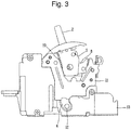
- FIG. 3 is a side view in which a mechanism of a molded-case circuit breaker according to the related art is in a coupled state. It illustrates an ON state.
- FIG. 4 is a perspective view illustrating the lower link.
- the present invention is contrived to solve the foregoing problem, and an aspect of the present invention is to provide a mechanism coupling structure of a molded-case circuit breaker for preventing a lower link from being released from a rotating pin by an arc pressure generated at the time of breaking.
- a mechanism coupling structure of a molded-case circuit breaker including a shaft to one side of which a movable contactor is coupled, and on a part of which a rotating pinhole is formed in a penetrating manner; a base assembly into which the shaft is rotatably accommodated and coupled, a switch mechanism coupled to an upper portion of the base assembly and exposed with a first lower link and a second lower link at a lower side thereof, and a rotating pin coupled in a penetrating manner to the first lower link, second lower link and rotating pinhole may be provided therein, wherein the rotating pin has a protruding portion for release prevention at one end thereof.
- the rotating pin may include a first rotating pin having a first protruding portion and a second rotating pin having a second protruding portion.
- first rotating pin and second rotating pin may be symmetrically provided in such a manner that the first protruding portion and second protruding portion face outward.
- first protruding portion and second protruding portion may be brought into contact with the first lower link and second lower link.
- an arc-shaped pinhole may be formed on the base assembly to expose the rotating pinhole when the shaft rotates, and a discharge groove configured to open a part of the pinhole may be formed at a lower portion of the first lower link and second lower link to discharge an arc pressure generated at the time of interruption to an outside thereof.
- the discharge groove may be formed by cutting a part of the first lower link and second lower link.
- a screw groove and a screw portion may be formed at body end portions of the first rotating pin and second rotating pin, respectively, to allow the first rotating pin and second rotating pin to be screw-coupled to each other.
- threads may be formed on rotating pin coupling holes of the first lower link and second lower link, and the first rotating pin and second rotating pin may be configured with screws.
- a part of an arc pressure generated at the time of interruption may be discharged through a discharge groove on a lower link, thereby having an effect of reducing a pressure acting on the lower link.
- a rotating pin may have a protruding portion, thereby having an effect of preventing the rotating pin from being released from a lower link even when receiving a force due to an arc pressure.
- FIG. 5 is a perspective view illustrating a mechanism coupling structure of a molded-case circuit breaker according to an embodiment of the present disclosure
- FIG. 6 is a front view illustrating a switch mechanism of a molded-case circuit breaker according to an embodiment of the present disclosure
- FIG. 7 is a side view in which a mechanism of a molded-case circuit breaker according to an embodiment of the present disclosure is in a coupled state
- FIGS. 8 and FIG. 9 are perspective views illustrating a rotating pin and a lower link applied to a mechanism of a molded-case circuit breaker according to an embodiment of the present disclosure.
- a mechanism coupling structure of a molded-case circuit breaker may include a shaft 21 to one side of which a movable contactor 25 is coupled, and on a part of which a rotating pinhole 22 is formed in a penetrating manner; a base assembly 30 into which the shaft 21 is rotatably accommodated and coupled, a switch mechanism 50 coupled to an upper portion of the base assembly 30 and exposed with a first lower link 40 and a second lower link 45 at a lower side thereof, and a rotating pin 60, 65 coupled in a penetrating manner to the first lower link 40, second lower link 45 and rotating pinhole 22, wherein the rotating pin 60, 65 has a protruding portion 61, 66 for release prevention at one end thereof.
- FIGS. 5 and 7 illustrate an exploded perspective view and a coupled front view of a mechanism of a molded-case circuit breaker according to an embodiment of the present disclosure
- FIG. 6 illustrates a front view of a switch mechanism.
- the mechanism of the molded-case circuit breaker may largely include a shaft assembly 20 including a movable contactor 25 and a shaft 21 to which the movable contactor 25 is coupled at one side thereof, a base assembly 30 provided with a contact portion, an extinguisher and a terminal portion including a fiexd contactor (not shown) and a movable contactor 25, and a switch mechanism 50 configured to rotate the shaft 21.
- a shaft assembly 20 including a movable contactor 25 and a shaft 21 to which the movable contactor 25 is coupled at one side thereof
- a base assembly 30 provided with a contact portion, an extinguisher and a terminal portion including a fiexd contactor (not shown) and a movable contactor 25, and a switch mechanism 50
- the base assembly 30 accommodates the movable contactor 25 and fiexd contactor to provide a space for accommodating the contact portion to perform breaking of an electrical circuit.
- the base assembly 30 may be configured with a pair of molds divided into the left and the right.
- the terminal portions are provided at both end portions of the base assembly 30 in a length direction.
- a power side (or load side) terminal portion 31 is provided at one end thereof, and a coupling portion 23 coupled to a load side (or power side) terminal portion (not shown) is provided at the other end thereof.
- Coupling holes 33, 34 to which the switch mechanism 50 can be coupled are formed in a penetrating manner on a part of the base assembly 30.
- Couplings pins 38, 39 are coupled in a penetrating manner to the coupling holes 33, 34, respectively.
- a mounting portion 35 on which the switch mechanism 50 can be mounted may be formed in a step or a groove shape on both sides of the base assembly 30 in a width direction.
- the coupling holes 33, 34 may be formed on a part of the mounting portion 35.
- a link operation portion 36 may be formed in a step or groove shape on a part of the mounting part 35 to operate the first lower link 40 and second lower link 45.
- a pinhole 37 that is a space in which the rotating pins 60, 65 which will be described later can be exposed and operated is formed on both sides of the base assembly 30.
- the pinhole 37 may be provided in a part of the link operation portion 36.
- the pinhole 37 may be formed in an arc shape.
- the pinhole 37 may be formed to be larger than an operating space of the rotating pins 60, 65.
- the switch mechanism 50 may include a pair of side plates 51 fixed to the base assembly 30, a switch lever 52 rotatably provided on the side plates 51, a handle 53 coupled to an upper portion of the switch lever 52 to transfer a user's power, a main spring 54 elastically operated by the rotation of the handle 53 to transfer power to a link shaft 55, and a first lower link 40 and a second lower link 45 upper ends of which are coupled to the link shaft 55 to move.
- Side plate coupling holes 51 a, 51 b are formed on the side plates 51, and side plates 51 are inserted and coupled into the base assembly 30 to allow the positions of the side plate coupling holes 51a, 51b to correspond to the coupling holes 33, 34 of the base assembly 30, and coupling is fixed and maintained by the coupling pins 38, 39 passing through the side plate coupling holes 51a, 51b and coupling holes 33, 34.
- the side plates 51 is inserted to surround the mounting portion 35, and the first lower link 40 and second lower link 45 are placed at a position of the pinhole 37 on the link operation portion 36 .
- the shaft assembly 20 is accommodated into the base assembly 30.
- the base assembly 30 may include a shaft 21, a movable contactor 25 coupled to one side of the shaft 21, and a terminal coupling portion 23 coupled to the other side of the shaft 21.
- the terminal coupling portion 23 is fixed to the other end of the base assembly 30, and the shaft 21 is rotatably provided to rotate the movable contactor 25 along with the shaft 21 when turned on or off.
- a rotating pinhole 22 into which the rotating pin 60, 65 can be inserted and coupled is formed in a penetrating manner on the shaft 21.
- the shaft 21 receives a force of the first lower link 40 and second lower link 45 by the rotating pin 60, 65 coupled to the rotating pinhole 22 to move.
- the rotating pin 60, 65 may be configured with a first rotating pin 60 and a second rotating pin 65.
- the first rotating pin 60 and second rotating pin 65 may be formed in the same shape.
- the first rotating pin 60 and second rotating pin 65 are inserted and coupled into the first lower link 40 and second lower link 45, respectively.
- a first protruding portion 61 and a second protruding portion 66 are formed at an outside of the first rotating pin 60 and second rotating pin 65, respectively.
- the first protruding portion 61 and second protruding portion 66 may be formed to have a larger diameter than a body portion of the first rotating pin 60 and second rotating pin 65.
- An inner surface 61 a of the first protruding portion 61 and an inner surface 66a of the second protruding portion 66 are brought into contact with the first lower link 40 and second lower link 45.
- the first rotating pin 60 and second rotating pin 65 are symmetrically provided to each other in such a manner that end portions of the body portion are brought into contact with each other (the first protruding portion 61 and second protruding portion 66 face outward. Accordingly, the first rotating pin 60 and second rotating pin 65 are brought into contact with the first lower link 40 and second lower link 45 to prevent movement so as not to be pulled inward as well as not to be released from the link 40 and second lower link 45.
- the first lower link 40 and second lower link 45 may be formed in an arc shape.
- the link shaft coupling holes 41, 46 may be formed at upper ends of the first lower link 40 and second lower link 45, respectively, and the rotating pin coupling holes 42, 47 at lower ends of the first lower link 40 and second lower link 45, respectively.
- a first discharge groove 43 and a second discharge groove 48 are formed on a part of the first lower link 40 and second lower link 45, respectively.
- the first discharge groove 43 and second discharge groove 48 may be formed by cutting a part of a rear portion on which the first lower link 40 and second lower link 45 are formed in a bent shape.
- inner surfaces of the first discharge groove 43 and second discharge groove 48 may be formed into a convex curved surface.
- a part of an arc pressure generated at the time of interruption may be discharged through a discharge groove on a lower link, thereby having an effect of reducing a pressure acting on the lower link.
- a rotating pin may have a protruding portion, thereby having an effect of preventing the rotating pin from being released from a lower link even when receiving a force due to an arc pressure.
- FIGS. 10A and 10B illustrate a mechanism coupling structure of a molded-case circuit breaker according to another embodiment of the present invention. Here, only a portion to which the lower link and the rotating pin are coupled is illustrated.
- a screw groove 62 is formed in a body end portion of the first rotating pin 60, and a screw portion 67 is formed in the body end portion of the second rotating pin 6 to allow the first rotating pin 60 and second rotating pin 65 to be screw-coupled to each other.
- FIG. 10B it is illustrated that threads are formed on rotating pin coupling holes 42a, 47a of the first lower link 40 and second lower link 45, and the first rotating pin 60a and second rotating pin 65a are configured with screws.
- the first rotating pin and second rotating pin may be coupled by screw-coupling, and thus have an excellent coupling force, thereby more effectively preventing the lower link from being released from the rotating pin.
Landscapes
- Breakers (AREA)
- Driving Mechanisms And Operating Circuits Of Arc-Extinguishing High-Tension Switches (AREA)
Abstract
Description
- The present disclosure relates to a mechanism coupling structure of a molded-case circuit breaker, and more particularly, to a mechanism coupling structure of a molded-case circuit breaker for preventing a lower link from being released from a rotating pin by an arc pressure generated at the time of breaking.
- In general, Molded-Case Circuit Breaker (MCCB) is an electric device for automatically breaking a circuit in the event of an electrical overload or short circuit to protect the circuit and a load thereof. The molded-case circuit breaker may largely include a terminal portion that can be connected to a power side or load side, a contact portion including a fiexd contactor and a movable contactor brought into contact with or separated from the fiexd contactor to connect or separate the circuit thereto or therefrom, a switch mechanism configured to move the movable contactor to provide power required for the switching of the circuit, a trip portion configured to sense an overcurrent or a short-circuit current at the switch mechanism and the power side to induce a tripping operation of the switch mechanism, and an extinguisher for extinguishing an arc generated when an abnormal current is interrupted.
-
FIG. 1 illustrates a circuit breaker according to the prior art. Here, it is shown that molded-case circuit breaker is disassembled into aswitch mechanism assembly 1, abase assembly 13, and ashaft assembly 16 in a state that an enclosure (case) is removed. Furthermore,FIG. 2 illustrates a front view of a switch mechanism of a molded-case circuit breaker according to the prior art. - Here, the switch mechanism is constituted by coupling a pair of
side plates 11 with a toggle link mechanism, a release mechanism, and the like. The toggle link mechanism includes aswitch lever 3 connected to ahandle 2 to rotate, anupper link 6 and alower link 4, connected to alink shaft 5, and provided between amovable contactor 7 and alatch 8. A release mechanism is connected to a lever-shaped latch 8 and alatch holder 9 to release thelatch 8 in conjunction with the operation of an overcurrent releasing device (not shown). Amain spring 10 is provided between theswitch lever 3 and thelink shaft 5 of the toggle link mechanism. - For a switching operation of the molded-case circuit breaker, when the
handle 2 is moved to an OFF position in a closed (ON) state, theupper link 6 andlower link 4 of the toggle link mechanism receives an elastic force of themain spring 10 to rotate theshaft 16 while being bent in a "¬"-shape such that themovable contactor 7 is separated from the fiexd contact (not shown) to open the circuit. - Furthermore, when an overcurrent flows during electrical conduction to operate an overcurrent release device (not shown), the release mechanism is activated by an output of the overcurrent release device to release the
latch 8 held in thelatch holder 9. As a result, thelatch 8 rotates in a counter-clockwise direction, and theswitch mechanism 8 performs a trip operation to switch themovable contact 7 to interrupt the current. - The mechanism coupling of a molded-case circuit breaker according to the prior art may couple the
lower link 4 and theshaft assembly 16 of the mechanism with a single rotatingpin 12 formed in a straight line shape. In other words, the operation of thelower link 4 rotates ashaft 17 by a rotatingpinhole 18 formed on theshaft 17 and coupled in a penetrating manner to apinhole 4a of thelower link 4. Here, theshaft assembly 16 is inserted and coupled into an accommodation space formed within thebase assembly 13. Furthermore, thebase assembly 13 is provided with athrough hole 14 formed in an arc shape to form a space in which the rotatingpin 12 can operate. -
FIG. 3 is a side view in which a mechanism of a molded-case circuit breaker according to the related art is in a coupled state. It illustrates an ON state.FIG. 4 is a perspective view illustrating the lower link. - In an electrical conduction (ON) state as illustrated in
FIG. 3 , thelower link 4 moves downward to completely cover the throughhole 14 of thebase assembly 13. However, in the coupled state of such a mechanism, an internal pressure generated at the time of interruption may leak along a fine gap between the components to act on thelower link 4. Accordingly, the leaked pressure may act on thelower link 4 coupled to the rotatingpin 12 with a force of pushing thelower link 4 in an outward direction, thereby causing a problem of releasing thelower link 4 from the rotatingpin 12. - The present invention is contrived to solve the foregoing problem, and an aspect of the present invention is to provide a mechanism coupling structure of a molded-case circuit breaker for preventing a lower link from being released from a rotating pin by an arc pressure generated at the time of breaking.
- A mechanism coupling structure of a molded-case circuit breaker according to an embodiment of the present disclosure including a shaft to one side of which a movable contactor is coupled, and on a part of which a rotating pinhole is formed in a penetrating manner; a base assembly into which the shaft is rotatably accommodated and coupled, a switch mechanism coupled to an upper portion of the base assembly and exposed with a first lower link and a second lower link at a lower side thereof, and a rotating pin coupled in a penetrating manner to the first lower link, second lower link and rotating pinhole may be provided therein, wherein the rotating pin has a protruding portion for release prevention at one end thereof.
- Here, the rotating pin may include a first rotating pin having a first protruding portion and a second rotating pin having a second protruding portion.
- Furthermore, the first rotating pin and second rotating pin may be symmetrically provided in such a manner that the first protruding portion and second protruding portion face outward.
- Furthermore, the first protruding portion and second protruding portion may be brought into contact with the first lower link and second lower link.
- Furthermore, an arc-shaped pinhole may be formed on the base assembly to expose the rotating pinhole when the shaft rotates, and a discharge groove configured to open a part of the pinhole may be formed at a lower portion of the first lower link and second lower link to discharge an arc pressure generated at the time of interruption to an outside thereof.
- Furthermore, the discharge groove may be formed by cutting a part of the first lower link and second lower link.
- Furthermore, a screw groove and a screw portion may be formed at body end portions of the first rotating pin and second rotating pin, respectively, to allow the first rotating pin and second rotating pin to be screw-coupled to each other.
- In addition, threads may be formed on rotating pin coupling holes of the first lower link and second lower link, and the first rotating pin and second rotating pin may be configured with screws.
- According to a mechanism coupling structure of a molded-case circuit breaker in accordance with an embodiment of the present disclosure, a part of an arc pressure generated at the time of interruption may be discharged through a discharge groove on a lower link, thereby having an effect of reducing a pressure acting on the lower link.
- Furthermore, a rotating pin may have a protruding portion, thereby having an effect of preventing the rotating pin from being released from a lower link even when receiving a force due to an arc pressure.
- The accompanying drawings, which are included to provide a further understanding of the invention and are incorporated in and constitute a part of this specification, illustrate embodiments of the invention and together with the description serve to explain the principles of the invention.
- In the drawings:
-
FIG. 1 is a perspective view illustrating a mechanism coupling structure of a molded-case circuit breaker according to the related art; -
FIG. 2 is a front view illustrating a switch mechanism of a molded-case circuit breaker according to the related art; -
FIG. 3 is a side view in which a mechanism of a molded-case circuit breaker according to the related art is in a coupled state; -
FIG. 4 is a perspective view illustrating a lower link applied to a molded-case circuit breaker according to the related art; -
FIG. 5 is a perspective view illustrating a mechanism coupling structure of a molded-case circuit breaker according to an embodiment of the present disclosure; -
FIG. 6 is a front view illustrating a switch mechanism of a molded-case circuit breaker according to an embodiment of the present disclosure; -
FIG. 7 is a side view in which a mechanism of a molded-case circuit breaker according to an embodiment of the present disclosure is in a coupled state; -
FIG. 8 is a perspective view illustrating a rotating pin applied to a mechanism of a molded-case circuit breaker according to an embodiment of the present disclosure; and -
FIG. 9 is a perspective view illustrating a lower link applied to a molded-case circuit breaker according to an embodiment of the present disclosure. -
FIGS. 10A and 10B are sectional views illustrating a mechanism coupling structure of a molded-case circuit breaker according to another embodiment of the present invention. - Hereinafter, a preferred embodiment of the present invention will be described in detail with reference to the accompanying drawings to such an extent that the present invention can be easily implemented by a person having ordinary skill in the art to which the present invention pertains, but it does not mean that the technical concept and scope of the present invention are limited due to this.
-
FIG. 5 is a perspective view illustrating a mechanism coupling structure of a molded-case circuit breaker according to an embodiment of the present disclosure, andFIG. 6 is a front view illustrating a switch mechanism of a molded-case circuit breaker according to an embodiment of the present disclosure, andFIG. 7 is a side view in which a mechanism of a molded-case circuit breaker according to an embodiment of the present disclosure is in a coupled state, andFIGS. 8 and FIG. 9 are perspective views illustrating a rotating pin and a lower link applied to a mechanism of a molded-case circuit breaker according to an embodiment of the present disclosure. A mechanism coupling structure of a molded-case circuit breaker according to each embodiment of the present disclosure will be described in detail with reference to the accompanying drawings. - A mechanism coupling structure of a molded-case circuit breaker according to an embodiment of the present disclosure may include a
shaft 21 to one side of which amovable contactor 25 is coupled, and on a part of which arotating pinhole 22 is formed in a penetrating manner; abase assembly 30 into which theshaft 21 is rotatably accommodated and coupled, aswitch mechanism 50 coupled to an upper portion of thebase assembly 30 and exposed with a firstlower link 40 and a secondlower link 45 at a lower side thereof, and a rotatingpin lower link 40, secondlower link 45 and rotatingpinhole 22, wherein the rotatingpin portion -
FIGS. 5 and7 illustrate an exploded perspective view and a coupled front view of a mechanism of a molded-case circuit breaker according to an embodiment of the present disclosure, andFIG. 6 illustrates a front view of a switch mechanism. The mechanism of the molded-case circuit breaker may largely include ashaft assembly 20 including amovable contactor 25 and ashaft 21 to which themovable contactor 25 is coupled at one side thereof, abase assembly 30 provided with a contact portion, an extinguisher and a terminal portion including a fiexd contactor (not shown) and amovable contactor 25, and aswitch mechanism 50 configured to rotate theshaft 21. Here, an entire enclosure of the molded-case circuit breaker is not illustrated. - The
base assembly 30 accommodates themovable contactor 25 and fiexd contactor to provide a space for accommodating the contact portion to perform breaking of an electrical circuit. Thebase assembly 30 may be configured with a pair of molds divided into the left and the right. The terminal portions are provided at both end portions of thebase assembly 30 in a length direction. Here, a power side (or load side)terminal portion 31 is provided at one end thereof, and acoupling portion 23 coupled to a load side (or power side) terminal portion (not shown) is provided at the other end thereof. - Coupling holes 33, 34 to which the
switch mechanism 50 can be coupled are formed in a penetrating manner on a part of thebase assembly 30. Couplings pins 38, 39 are coupled in a penetrating manner to the coupling holes 33, 34, respectively. - A mounting
portion 35 on which theswitch mechanism 50 can be mounted may be formed in a step or a groove shape on both sides of thebase assembly 30 in a width direction. The coupling holes 33, 34 may be formed on a part of the mountingportion 35. Alink operation portion 36 may be formed in a step or groove shape on a part of the mountingpart 35 to operate the firstlower link 40 and secondlower link 45. - A
pinhole 37 that is a space in which therotating pins base assembly 30. Thepinhole 37 may be provided in a part of thelink operation portion 36. Thepinhole 37 may be formed in an arc shape. Thepinhole 37 may be formed to be larger than an operating space of therotating pins - The
switch mechanism 50 may include a pair ofside plates 51 fixed to thebase assembly 30, aswitch lever 52 rotatably provided on theside plates 51, ahandle 53 coupled to an upper portion of theswitch lever 52 to transfer a user's power, amain spring 54 elastically operated by the rotation of thehandle 53 to transfer power to alink shaft 55, and a firstlower link 40 and a secondlower link 45 upper ends of which are coupled to thelink shaft 55 to move. - Side plate coupling holes 51 a, 51 b are formed on the
side plates 51, andside plates 51 are inserted and coupled into thebase assembly 30 to allow the positions of the sideplate coupling holes base assembly 30, and coupling is fixed and maintained by the coupling pins 38, 39 passing through the sideplate coupling holes side plates 51 is inserted to surround the mountingportion 35, and the firstlower link 40 and secondlower link 45 are placed at a position of thepinhole 37 on thelink operation portion 36 . - The
shaft assembly 20 is accommodated into thebase assembly 30. Thebase assembly 30 may include ashaft 21, amovable contactor 25 coupled to one side of theshaft 21, and aterminal coupling portion 23 coupled to the other side of theshaft 21. Theterminal coupling portion 23 is fixed to the other end of thebase assembly 30, and theshaft 21 is rotatably provided to rotate themovable contactor 25 along with theshaft 21 when turned on or off. - A
rotating pinhole 22 into which therotating pin shaft 21. Theshaft 21 receives a force of the firstlower link 40 and secondlower link 45 by the rotatingpin rotating pinhole 22 to move. - The rotating
pin rotating pin 60 and a secondrotating pin 65. The firstrotating pin 60 and secondrotating pin 65 may be formed in the same shape. The firstrotating pin 60 and secondrotating pin 65 are inserted and coupled into the firstlower link 40 and secondlower link 45, respectively. - A first protruding
portion 61 and a second protrudingportion 66 are formed at an outside of the firstrotating pin 60 and secondrotating pin 65, respectively. The first protrudingportion 61 and second protrudingportion 66 may be formed to have a larger diameter than a body portion of the firstrotating pin 60 and secondrotating pin 65. Aninner surface 61 a of the first protrudingportion 61 and aninner surface 66a of the second protrudingportion 66 are brought into contact with the firstlower link 40 and secondlower link 45. - Referring to
FIG. 6 , the firstrotating pin 60 and secondrotating pin 65 are symmetrically provided to each other in such a manner that end portions of the body portion are brought into contact with each other (the first protrudingportion 61 and second protrudingportion 66 face outward. Accordingly, the firstrotating pin 60 and secondrotating pin 65 are brought into contact with the firstlower link 40 and secondlower link 45 to prevent movement so as not to be pulled inward as well as not to be released from thelink 40 and secondlower link 45. - Referring to
FIG. 9 , the firstlower link 40 and secondlower link 45 may be formed in an arc shape. The link shaft coupling holes 41, 46 may be formed at upper ends of the firstlower link 40 and secondlower link 45, respectively, and the rotating pin coupling holes 42, 47 at lower ends of the firstlower link 40 and secondlower link 45, respectively. - A
first discharge groove 43 and asecond discharge groove 48 are formed on a part of the firstlower link 40 and secondlower link 45, respectively. Thefirst discharge groove 43 andsecond discharge groove 48 may be formed by cutting a part of a rear portion on which the firstlower link 40 and secondlower link 45 are formed in a bent shape. Here, inner surfaces of thefirst discharge groove 43 andsecond discharge groove 48 may be formed into a convex curved surface. - Referring to
FIG. 7 , though a part of thepinhole 37 is open by thefirst discharge groove 43 andsecond discharge groove 48 of the firstlower link 40 and secondlower link 45 in an ON state of the circuit breaker to form an exhaust space (B), and most of an arc pressure generated at the time of interruption is discharged through an arc extinguisher and an exhaust portion (A), a part of the residual pressure may be also discharged through the exhaust space (B), thereby reducing a pressure receiving at the firstlower link 40 and secondlower link 45 due to an arc impact. - According to a mechanism coupling structure of a molded-case circuit breaker in accordance with an embodiment of the present disclosure, a part of an arc pressure generated at the time of interruption may be discharged through a discharge groove on a lower link, thereby having an effect of reducing a pressure acting on the lower link. Furthermore, a rotating pin may have a protruding portion, thereby having an effect of preventing the rotating pin from being released from a lower link even when receiving a force due to an arc pressure.
-
FIGS. 10A and 10B illustrate a mechanism coupling structure of a molded-case circuit breaker according to another embodiment of the present invention. Here, only a portion to which the lower link and the rotating pin are coupled is illustrated. - According to the present embodiment illustrated in
FIG. 10A , it is illustrated that ascrew groove 62 is formed in a body end portion of the firstrotating pin 60, and ascrew portion 67 is formed in the body end portion of the secondrotating pin 6 to allow the firstrotating pin 60 and secondrotating pin 65 to be screw-coupled to each other. - According to the present embodiment illustrated in
FIG. 10B , it is illustrated that threads are formed on rotatingpin coupling holes lower link 40 and secondlower link 45, and the firstrotating pin 60a and secondrotating pin 65a are configured with screws. - According to the embodiments illustrated in
FIGS. 10A and 10B , the first rotating pin and second rotating pin may be coupled by screw-coupling, and thus have an excellent coupling force, thereby more effectively preventing the lower link from being released from the rotating pin. - It will be apparent to those skilled in this art that various changes and modifications may be made thereto without departing from the gist of the present invention. Accordingly, it should be noted that the embodiments disclosed in the present invention are only illustrative and not limitative to the concept of the present invention, and the scope of the concept of the invention is not limited by those embodiments. The scope protected by the present invention should be construed by the accompanying claims, and all the concept within the equivalent scope of the invention should be construed to be included in the scope of the right of the present invention.
Claims (8)
- A mechanism coupling structure of a molded-case circuit breaker, comprising a shaft (21) to one side of which a movable contactor (25) is coupled, and on a part of which a rotating pinhole (22) is formed in a penetrating manner; a base assembly (3) into which the shaft (21) is rotatably accommodated and coupled, a switch mechanism (50) coupled to an upper portion of the base assembly (30) and exposed with a first lower link (40) and a second lower link (45) at a lower side thereof, and a rotating pin (60, 65) coupled in a penetrating manner to the first lower link (40), second lower link (45) and rotating pinhole (22),
wherein the rotating pin (60, 65) has a protruding portion (61, 66) for release prevention at one end thereof. - The mechanism coupling structure of a molded-case circuit breaker of claim 1, wherein the rotating pin (60, 65) comprises a first rotating pin (60) having a first protruding portion (61) and a second rotating pin (65) having a second protruding portion (66).
- The mechanism coupling structure of a molded-case circuit breaker of claim 1, wherein the first rotating pin (60) and second rotating pin (65) are symmetrically provided in such a manner that the first protruding portion (61) and second protruding portion (66) face outward.
- The mechanism coupling structure of a molded-case circuit breaker of claim 1, wherein the first protruding portion (61) and second protruding portion (66) are brought into contact with the first lower link (40) and second lower link (45).
- The mechanism coupling structure of a molded-case circuit breaker of claim 1, wherein an arc-shaped pinhole (37) is formed on the base assembly (30) to expose the rotating pinhole (22) when the shaft (21) rotates, and a discharge groove (43, 48) configured to open a part of the pinhole (37) is formed at a lower portion of the first lower link (40) and second lower link (45) to discharge an arc pressure generated at the time of interruption to an outside thereof.
- The mechanism coupling structure of a molded-case circuit breaker of claim 5, wherein the discharge groove (43, 48) is formed by cutting a part of the first lower link (40) and second lower link (45).
- The mechanism coupling structure of a molded-case circuit breaker of claim 1, wherein a screw groove (62) and a screw portion (67) are formed at body end portions of the first rotating pin (60) and second rotating pin (65), respectively, to allow the first rotating pin (60) and second rotating pin (65) to be screw-coupled to each other.
- The mechanism coupling structure of a molded-case circuit breaker of claim 1, wherein threads are formed on rotating pin coupling holes (42a, 47a) of the first lower link (40) and second lower link (45), and the first rotating pin (60) and second rotating pin (65) are configured with screws.
Applications Claiming Priority (1)
| Application Number | Priority Date | Filing Date | Title |
|---|---|---|---|
| KR1020160093670A KR101810472B1 (en) | 2016-07-22 | 2016-07-22 | Coupling Structure of Mechanism of Molded Case Circuit Breaker |
Publications (2)
| Publication Number | Publication Date |
|---|---|
| EP3273464A1 true EP3273464A1 (en) | 2018-01-24 |
| EP3273464B1 EP3273464B1 (en) | 2019-09-18 |
Family
ID=58227916
Family Applications (1)
| Application Number | Title | Priority Date | Filing Date |
|---|---|---|---|
| EP17158437.8A Active EP3273464B1 (en) | 2016-07-22 | 2017-02-28 | Mechanism coupling structure of molded case circuit breaker |
Country Status (5)
| Country | Link |
|---|---|
| US (1) | US10147578B2 (en) |
| EP (1) | EP3273464B1 (en) |
| KR (1) | KR101810472B1 (en) |
| CN (1) | CN107644794B (en) |
| ES (1) | ES2760549T3 (en) |
Families Citing this family (1)
| Publication number | Priority date | Publication date | Assignee | Title |
|---|---|---|---|---|
| EP4260355A4 (en) * | 2020-12-14 | 2024-09-04 | ABB S.p.A. | Adjustment mechanism for circuit breaker and corresponding circuit breaker |
Citations (4)
| Publication number | Priority date | Publication date | Assignee | Title |
|---|---|---|---|---|
| US6495781B2 (en) * | 2000-12-27 | 2002-12-17 | General Electric Company | Handle position indicator |
| EP2023365A2 (en) * | 2007-08-10 | 2009-02-11 | LS Industrial Systems Co., Ltd | Molded case circuit breaker with contact on mechanism |
| US20130206558A1 (en) * | 2012-02-09 | 2013-08-15 | Thomas Bunk | Switching unit for an electrical switching device |
| CN203644705U (en) * | 2013-12-27 | 2014-06-11 | 常熟开关制造有限公司(原常熟开关厂) | Circuit breaker opening lever |
Family Cites Families (14)
| Publication number | Priority date | Publication date | Assignee | Title |
|---|---|---|---|---|
| US4737603A (en) * | 1987-07-09 | 1988-04-12 | Service Machine Company | Isolation switch |
| JPH0575944A (en) | 1991-09-10 | 1993-03-26 | Sony Corp | Television receiver |
| JPH09320442A (en) | 1996-05-30 | 1997-12-12 | Matsushita Electric Works Ltd | Circuit breaker |
| JP3548700B2 (en) | 1998-08-06 | 2004-07-28 | 三菱電機株式会社 | Circuit breaker |
| JP3778051B2 (en) | 2001-10-26 | 2006-05-24 | 松下電工株式会社 | Circuit breaker |
| US7218192B2 (en) * | 2004-10-01 | 2007-05-15 | Eaton Corporation | Lockable fastener and circuit breaker employing the same |
| KR100662751B1 (en) | 2005-09-30 | 2007-01-02 | 엘에스산전 주식회사 | 4-pole wiring breaker |
| KR100676967B1 (en) * | 2005-12-28 | 2007-02-02 | 엘에스산전 주식회사 | Circuit breaker |
| KR101027780B1 (en) | 2006-10-17 | 2011-04-07 | 현대중공업 주식회사 | Arc pressure trip device of circuit breaker |
| KR101010083B1 (en) | 2008-12-04 | 2011-01-24 | 엘에스산전 주식회사 | Cable operation link device of wiring breaker |
| KR101191158B1 (en) * | 2009-12-04 | 2012-10-15 | 엘에스산전 주식회사 | Rotating pin compensation device of 4-pole wiring breaker |
| KR20120001549U (en) | 2010-08-26 | 2012-03-07 | 주식회사 유니세트 | Hinge pin for connecting operation member |
| KR20120004950A (en) | 2011-12-21 | 2012-01-13 | 한국벤토나이트 주식회사 | Sensor type automatic vinyl house snow sprayer |
| EP2871653B1 (en) | 2013-10-17 | 2017-04-26 | LSIS Co., Ltd. | Circuit breaker |
-
2016
- 2016-07-22 KR KR1020160093670A patent/KR101810472B1/en active Active
-
2017
- 2017-02-28 EP EP17158437.8A patent/EP3273464B1/en active Active
- 2017-02-28 ES ES17158437T patent/ES2760549T3/en active Active
- 2017-03-29 US US15/473,530 patent/US10147578B2/en active Active
- 2017-06-06 CN CN201710419628.9A patent/CN107644794B/en active Active
Patent Citations (4)
| Publication number | Priority date | Publication date | Assignee | Title |
|---|---|---|---|---|
| US6495781B2 (en) * | 2000-12-27 | 2002-12-17 | General Electric Company | Handle position indicator |
| EP2023365A2 (en) * | 2007-08-10 | 2009-02-11 | LS Industrial Systems Co., Ltd | Molded case circuit breaker with contact on mechanism |
| US20130206558A1 (en) * | 2012-02-09 | 2013-08-15 | Thomas Bunk | Switching unit for an electrical switching device |
| CN203644705U (en) * | 2013-12-27 | 2014-06-11 | 常熟开关制造有限公司(原常熟开关厂) | Circuit breaker opening lever |
Also Published As
| Publication number | Publication date |
|---|---|
| US10147578B2 (en) | 2018-12-04 |
| ES2760549T3 (en) | 2020-05-14 |
| KR101810472B1 (en) | 2017-12-19 |
| EP3273464B1 (en) | 2019-09-18 |
| CN107644794B (en) | 2019-08-06 |
| US20180025876A1 (en) | 2018-01-25 |
| CN107644794A (en) | 2018-01-30 |
Similar Documents
| Publication | Publication Date | Title |
|---|---|---|
| EP2492944B1 (en) | Circuit breaker | |
| KR101026306B1 (en) | Circuit breaker with instantaneous trip device | |
| EP2023365B1 (en) | Molded case circuit breaker with contact on mechanism | |
| CN108511283B (en) | Molded case circuit breaker with primary contact interlock | |
| ES2761845T3 (en) | Molded Case Circuit Breaker | |
| EP3273464B1 (en) | Mechanism coupling structure of molded case circuit breaker | |
| EP3594986B1 (en) | Switching mechanism of circuit breaker | |
| EP2107588A2 (en) | Circuit breaker | |
| KR101158639B1 (en) | A switching mechanism for circuit braker | |
| JPWO2001071750A1 (en) | circuit breaker | |
| CN103109341B (en) | Composite switchgear and switchgear module for the composite switchgear | |
| CN103681145B (en) | Arc-control device and adopt the chopper of this arc-control device | |
| KR100574424B1 (en) | Circuit breaker | |
| KR100379691B1 (en) | Contact point closing/open apparatus for circuit breaker | |
| JP4641008B2 (en) | Circuit breaker | |
| KR100631827B1 (en) | Pressure trip device of circuit breaker | |
| KR20210053079A (en) | Molded Case Circuit Breaker | |
| KR200376476Y1 (en) | A Circuit Breaker Having a Safety Device | |
| KR102111462B1 (en) | Molded Case Circuit Breaker | |
| KR101076288B1 (en) | Wiring breaker with quick reverse mechanism | |
| JP3933387B2 (en) | Circuit breaker | |
| KR200382138Y1 (en) | A Mould Cased Circuit Breaker | |
| JP3862498B2 (en) | Circuit breaker | |
| JP5554210B2 (en) | Circuit breaker | |
| JP2002208339A (en) | Circuit breaker |
Legal Events
| Date | Code | Title | Description |
|---|---|---|---|
| PUAI | Public reference made under article 153(3) epc to a published international application that has entered the european phase |
Free format text: ORIGINAL CODE: 0009012 |
|
| STAA | Information on the status of an ep patent application or granted ep patent |
Free format text: STATUS: THE APPLICATION HAS BEEN PUBLISHED |
|
| AK | Designated contracting states |
Kind code of ref document: A1 Designated state(s): AL AT BE BG CH CY CZ DE DK EE ES FI FR GB GR HR HU IE IS IT LI LT LU LV MC MK MT NL NO PL PT RO RS SE SI SK SM TR |
|
| AX | Request for extension of the european patent |
Extension state: BA ME |
|
| STAA | Information on the status of an ep patent application or granted ep patent |
Free format text: STATUS: REQUEST FOR EXAMINATION WAS MADE |
|
| 17P | Request for examination filed |
Effective date: 20180718 |
|
| RBV | Designated contracting states (corrected) |
Designated state(s): AL AT BE BG CH CY CZ DE DK EE ES FI FR GB GR HR HU IE IS IT LI LT LU LV MC MK MT NL NO PL PT RO RS SE SI SK SM TR |
|
| GRAP | Despatch of communication of intention to grant a patent |
Free format text: ORIGINAL CODE: EPIDOSNIGR1 |
|
| STAA | Information on the status of an ep patent application or granted ep patent |
Free format text: STATUS: GRANT OF PATENT IS INTENDED |
|
| RIC1 | Information provided on ipc code assigned before grant |
Ipc: H01H 71/02 20060101AFI20190320BHEP Ipc: H01H 71/10 20060101ALI20190320BHEP |
|
| INTG | Intention to grant announced |
Effective date: 20190405 |
|
| RIN1 | Information on inventor provided before grant (corrected) |
Inventor name: YOO, SUNGROK Inventor name: OH, KIHWAN |
|
| GRAS | Grant fee paid |
Free format text: ORIGINAL CODE: EPIDOSNIGR3 |
|
| GRAJ | Information related to disapproval of communication of intention to grant by the applicant or resumption of examination proceedings by the epo deleted |
Free format text: ORIGINAL CODE: EPIDOSDIGR1 |
|
| GRAL | Information related to payment of fee for publishing/printing deleted |
Free format text: ORIGINAL CODE: EPIDOSDIGR3 |
|
| STAA | Information on the status of an ep patent application or granted ep patent |
Free format text: STATUS: REQUEST FOR EXAMINATION WAS MADE |
|
| GRAR | Information related to intention to grant a patent recorded |
Free format text: ORIGINAL CODE: EPIDOSNIGR71 |
|
| STAA | Information on the status of an ep patent application or granted ep patent |
Free format text: STATUS: GRANT OF PATENT IS INTENDED |
|
| GRAA | (expected) grant |
Free format text: ORIGINAL CODE: 0009210 |
|
| STAA | Information on the status of an ep patent application or granted ep patent |
Free format text: STATUS: THE PATENT HAS BEEN GRANTED |
|
| INTC | Intention to grant announced (deleted) | ||
| AK | Designated contracting states |
Kind code of ref document: B1 Designated state(s): AL AT BE BG CH CY CZ DE DK EE ES FI FR GB GR HR HU IE IS IT LI LT LU LV MC MK MT NL NO PL PT RO RS SE SI SK SM TR |
|
| INTG | Intention to grant announced |
Effective date: 20190812 |
|
| REG | Reference to a national code |
Ref country code: GB Ref legal event code: FG4D |
|
| REG | Reference to a national code |
Ref country code: CH Ref legal event code: EP |
|
| REG | Reference to a national code |
Ref country code: DE Ref legal event code: R096 Ref document number: 602017007065 Country of ref document: DE |
|
| REG | Reference to a national code |
Ref country code: AT Ref legal event code: REF Ref document number: 1182292 Country of ref document: AT Kind code of ref document: T Effective date: 20191015 |
|
| REG | Reference to a national code |
Ref country code: IE Ref legal event code: FG4D |
|
| REG | Reference to a national code |
Ref country code: NL Ref legal event code: MP Effective date: 20190918 |
|
| PG25 | Lapsed in a contracting state [announced via postgrant information from national office to epo] |
Ref country code: LT Free format text: LAPSE BECAUSE OF FAILURE TO SUBMIT A TRANSLATION OF THE DESCRIPTION OR TO PAY THE FEE WITHIN THE PRESCRIBED TIME-LIMIT Effective date: 20190918 Ref country code: FI Free format text: LAPSE BECAUSE OF FAILURE TO SUBMIT A TRANSLATION OF THE DESCRIPTION OR TO PAY THE FEE WITHIN THE PRESCRIBED TIME-LIMIT Effective date: 20190918 Ref country code: SE Free format text: LAPSE BECAUSE OF FAILURE TO SUBMIT A TRANSLATION OF THE DESCRIPTION OR TO PAY THE FEE WITHIN THE PRESCRIBED TIME-LIMIT Effective date: 20190918 Ref country code: HR Free format text: LAPSE BECAUSE OF FAILURE TO SUBMIT A TRANSLATION OF THE DESCRIPTION OR TO PAY THE FEE WITHIN THE PRESCRIBED TIME-LIMIT Effective date: 20190918 Ref country code: BG Free format text: LAPSE BECAUSE OF FAILURE TO SUBMIT A TRANSLATION OF THE DESCRIPTION OR TO PAY THE FEE WITHIN THE PRESCRIBED TIME-LIMIT Effective date: 20191218 Ref country code: NO Free format text: LAPSE BECAUSE OF FAILURE TO SUBMIT A TRANSLATION OF THE DESCRIPTION OR TO PAY THE FEE WITHIN THE PRESCRIBED TIME-LIMIT Effective date: 20191218 |
|
| REG | Reference to a national code |
Ref country code: LT Ref legal event code: MG4D |
|
| PG25 | Lapsed in a contracting state [announced via postgrant information from national office to epo] |
Ref country code: AL Free format text: LAPSE BECAUSE OF FAILURE TO SUBMIT A TRANSLATION OF THE DESCRIPTION OR TO PAY THE FEE WITHIN THE PRESCRIBED TIME-LIMIT Effective date: 20190918 Ref country code: LV Free format text: LAPSE BECAUSE OF FAILURE TO SUBMIT A TRANSLATION OF THE DESCRIPTION OR TO PAY THE FEE WITHIN THE PRESCRIBED TIME-LIMIT Effective date: 20190918 Ref country code: RS Free format text: LAPSE BECAUSE OF FAILURE TO SUBMIT A TRANSLATION OF THE DESCRIPTION OR TO PAY THE FEE WITHIN THE PRESCRIBED TIME-LIMIT Effective date: 20190918 Ref country code: GR Free format text: LAPSE BECAUSE OF FAILURE TO SUBMIT A TRANSLATION OF THE DESCRIPTION OR TO PAY THE FEE WITHIN THE PRESCRIBED TIME-LIMIT Effective date: 20191219 |
|
| REG | Reference to a national code |
Ref country code: AT Ref legal event code: MK05 Ref document number: 1182292 Country of ref document: AT Kind code of ref document: T Effective date: 20190918 |
|
| PG25 | Lapsed in a contracting state [announced via postgrant information from national office to epo] |
Ref country code: PL Free format text: LAPSE BECAUSE OF FAILURE TO SUBMIT A TRANSLATION OF THE DESCRIPTION OR TO PAY THE FEE WITHIN THE PRESCRIBED TIME-LIMIT Effective date: 20190918 Ref country code: EE Free format text: LAPSE BECAUSE OF FAILURE TO SUBMIT A TRANSLATION OF THE DESCRIPTION OR TO PAY THE FEE WITHIN THE PRESCRIBED TIME-LIMIT Effective date: 20190918 Ref country code: PT Free format text: LAPSE BECAUSE OF FAILURE TO SUBMIT A TRANSLATION OF THE DESCRIPTION OR TO PAY THE FEE WITHIN THE PRESCRIBED TIME-LIMIT Effective date: 20200120 Ref country code: AT Free format text: LAPSE BECAUSE OF FAILURE TO SUBMIT A TRANSLATION OF THE DESCRIPTION OR TO PAY THE FEE WITHIN THE PRESCRIBED TIME-LIMIT Effective date: 20190918 Ref country code: NL Free format text: LAPSE BECAUSE OF FAILURE TO SUBMIT A TRANSLATION OF THE DESCRIPTION OR TO PAY THE FEE WITHIN THE PRESCRIBED TIME-LIMIT Effective date: 20190918 Ref country code: RO Free format text: LAPSE BECAUSE OF FAILURE TO SUBMIT A TRANSLATION OF THE DESCRIPTION OR TO PAY THE FEE WITHIN THE PRESCRIBED TIME-LIMIT Effective date: 20190918 |
|
| REG | Reference to a national code |
Ref country code: ES Ref legal event code: FG2A Ref document number: 2760549 Country of ref document: ES Kind code of ref document: T3 Effective date: 20200514 |
|
| PG25 | Lapsed in a contracting state [announced via postgrant information from national office to epo] |
Ref country code: SK Free format text: LAPSE BECAUSE OF FAILURE TO SUBMIT A TRANSLATION OF THE DESCRIPTION OR TO PAY THE FEE WITHIN THE PRESCRIBED TIME-LIMIT Effective date: 20190918 Ref country code: SM Free format text: LAPSE BECAUSE OF FAILURE TO SUBMIT A TRANSLATION OF THE DESCRIPTION OR TO PAY THE FEE WITHIN THE PRESCRIBED TIME-LIMIT Effective date: 20190918 Ref country code: IS Free format text: LAPSE BECAUSE OF FAILURE TO SUBMIT A TRANSLATION OF THE DESCRIPTION OR TO PAY THE FEE WITHIN THE PRESCRIBED TIME-LIMIT Effective date: 20200224 Ref country code: CZ Free format text: LAPSE BECAUSE OF FAILURE TO SUBMIT A TRANSLATION OF THE DESCRIPTION OR TO PAY THE FEE WITHIN THE PRESCRIBED TIME-LIMIT Effective date: 20190918 |
|
| REG | Reference to a national code |
Ref country code: DE Ref legal event code: R097 Ref document number: 602017007065 Country of ref document: DE |
|
| PLBE | No opposition filed within time limit |
Free format text: ORIGINAL CODE: 0009261 |
|
| STAA | Information on the status of an ep patent application or granted ep patent |
Free format text: STATUS: NO OPPOSITION FILED WITHIN TIME LIMIT |
|
| PG2D | Information on lapse in contracting state deleted |
Ref country code: IS |
|
| PG25 | Lapsed in a contracting state [announced via postgrant information from national office to epo] |
Ref country code: DK Free format text: LAPSE BECAUSE OF FAILURE TO SUBMIT A TRANSLATION OF THE DESCRIPTION OR TO PAY THE FEE WITHIN THE PRESCRIBED TIME-LIMIT Effective date: 20190918 Ref country code: IS Free format text: LAPSE BECAUSE OF FAILURE TO SUBMIT A TRANSLATION OF THE DESCRIPTION OR TO PAY THE FEE WITHIN THE PRESCRIBED TIME-LIMIT Effective date: 20200119 |
|
| 26N | No opposition filed |
Effective date: 20200619 |
|
| PG25 | Lapsed in a contracting state [announced via postgrant information from national office to epo] |
Ref country code: SI Free format text: LAPSE BECAUSE OF FAILURE TO SUBMIT A TRANSLATION OF THE DESCRIPTION OR TO PAY THE FEE WITHIN THE PRESCRIBED TIME-LIMIT Effective date: 20190918 |
|
| REG | Reference to a national code |
Ref country code: CH Ref legal event code: PL |
|
| REG | Reference to a national code |
Ref country code: BE Ref legal event code: MM Effective date: 20200229 |
|
| PG25 | Lapsed in a contracting state [announced via postgrant information from national office to epo] |
Ref country code: LU Free format text: LAPSE BECAUSE OF NON-PAYMENT OF DUE FEES Effective date: 20200228 Ref country code: MC Free format text: LAPSE BECAUSE OF FAILURE TO SUBMIT A TRANSLATION OF THE DESCRIPTION OR TO PAY THE FEE WITHIN THE PRESCRIBED TIME-LIMIT Effective date: 20190918 |
|
| PG25 | Lapsed in a contracting state [announced via postgrant information from national office to epo] |
Ref country code: CH Free format text: LAPSE BECAUSE OF NON-PAYMENT OF DUE FEES Effective date: 20200229 Ref country code: LI Free format text: LAPSE BECAUSE OF NON-PAYMENT OF DUE FEES Effective date: 20200229 |
|
| PG25 | Lapsed in a contracting state [announced via postgrant information from national office to epo] |
Ref country code: IE Free format text: LAPSE BECAUSE OF NON-PAYMENT OF DUE FEES Effective date: 20200228 |
|
| PG25 | Lapsed in a contracting state [announced via postgrant information from national office to epo] |
Ref country code: BE Free format text: LAPSE BECAUSE OF NON-PAYMENT OF DUE FEES Effective date: 20200229 |
|
| PGFP | Annual fee paid to national office [announced via postgrant information from national office to epo] |
Ref country code: FR Payment date: 20211223 Year of fee payment: 6 Ref country code: GB Payment date: 20211220 Year of fee payment: 6 |
|
| PGFP | Annual fee paid to national office [announced via postgrant information from national office to epo] |
Ref country code: DE Payment date: 20211220 Year of fee payment: 6 |
|
| PG25 | Lapsed in a contracting state [announced via postgrant information from national office to epo] |
Ref country code: TR Free format text: LAPSE BECAUSE OF FAILURE TO SUBMIT A TRANSLATION OF THE DESCRIPTION OR TO PAY THE FEE WITHIN THE PRESCRIBED TIME-LIMIT Effective date: 20190918 Ref country code: MT Free format text: LAPSE BECAUSE OF FAILURE TO SUBMIT A TRANSLATION OF THE DESCRIPTION OR TO PAY THE FEE WITHIN THE PRESCRIBED TIME-LIMIT Effective date: 20190918 Ref country code: CY Free format text: LAPSE BECAUSE OF FAILURE TO SUBMIT A TRANSLATION OF THE DESCRIPTION OR TO PAY THE FEE WITHIN THE PRESCRIBED TIME-LIMIT Effective date: 20190918 |
|
| PGFP | Annual fee paid to national office [announced via postgrant information from national office to epo] |
Ref country code: IT Payment date: 20211221 Year of fee payment: 6 Ref country code: ES Payment date: 20220311 Year of fee payment: 6 |
|
| PG25 | Lapsed in a contracting state [announced via postgrant information from national office to epo] |
Ref country code: MK Free format text: LAPSE BECAUSE OF FAILURE TO SUBMIT A TRANSLATION OF THE DESCRIPTION OR TO PAY THE FEE WITHIN THE PRESCRIBED TIME-LIMIT Effective date: 20190918 |
|
| REG | Reference to a national code |
Ref country code: DE Ref legal event code: R119 Ref document number: 602017007065 Country of ref document: DE |
|
| GBPC | Gb: european patent ceased through non-payment of renewal fee |
Effective date: 20230228 |
|
| PG25 | Lapsed in a contracting state [announced via postgrant information from national office to epo] |
Ref country code: GB Free format text: LAPSE BECAUSE OF NON-PAYMENT OF DUE FEES Effective date: 20230228 |
|
| PG25 | Lapsed in a contracting state [announced via postgrant information from national office to epo] |
Ref country code: IT Free format text: LAPSE BECAUSE OF NON-PAYMENT OF DUE FEES Effective date: 20230228 Ref country code: GB Free format text: LAPSE BECAUSE OF NON-PAYMENT OF DUE FEES Effective date: 20230228 Ref country code: FR Free format text: LAPSE BECAUSE OF NON-PAYMENT OF DUE FEES Effective date: 20230228 Ref country code: DE Free format text: LAPSE BECAUSE OF NON-PAYMENT OF DUE FEES Effective date: 20230901 |
|
| REG | Reference to a national code |
Ref country code: ES Ref legal event code: FD2A Effective date: 20240405 |
|
| PG25 | Lapsed in a contracting state [announced via postgrant information from national office to epo] |
Ref country code: ES Free format text: LAPSE BECAUSE OF NON-PAYMENT OF DUE FEES Effective date: 20230301 |
|
| PG25 | Lapsed in a contracting state [announced via postgrant information from national office to epo] |
Ref country code: ES Free format text: LAPSE BECAUSE OF NON-PAYMENT OF DUE FEES Effective date: 20230301 |