EP3273424A1 - System and method of aircraft surveillance and tracking - Google Patents
System and method of aircraft surveillance and tracking Download PDFInfo
- Publication number
- EP3273424A1 EP3273424A1 EP16382356.0A EP16382356A EP3273424A1 EP 3273424 A1 EP3273424 A1 EP 3273424A1 EP 16382356 A EP16382356 A EP 16382356A EP 3273424 A1 EP3273424 A1 EP 3273424A1
- Authority
- EP
- European Patent Office
- Prior art keywords
- aircraft
- sector
- data
- header
- sectors
- Prior art date
- Legal status (The legal status is an assumption and is not a legal conclusion. Google has not performed a legal analysis and makes no representation as to the accuracy of the status listed.)
- Granted
Links
Images


Classifications
-
- H—ELECTRICITY
- H04—ELECTRIC COMMUNICATION TECHNIQUE
- H04W—WIRELESS COMMUNICATION NETWORKS
- H04W4/00—Services specially adapted for wireless communication networks; Facilities therefor
- H04W4/02—Services making use of location information
- H04W4/029—Location-based management or tracking services
-
- G—PHYSICS
- G08—SIGNALLING
- G08G—TRAFFIC CONTROL SYSTEMS
- G08G5/00—Traffic control systems for aircraft
- G08G5/20—Arrangements for acquiring, generating, sharing or displaying traffic information
- G08G5/22—Arrangements for acquiring, generating, sharing or displaying traffic information located on the ground
-
- G—PHYSICS
- G08—SIGNALLING
- G08G—TRAFFIC CONTROL SYSTEMS
- G08G5/00—Traffic control systems for aircraft
- G08G5/20—Arrangements for acquiring, generating, sharing or displaying traffic information
- G08G5/26—Transmission of traffic-related information between aircraft and ground stations
-
- G—PHYSICS
- G08—SIGNALLING
- G08G—TRAFFIC CONTROL SYSTEMS
- G08G5/00—Traffic control systems for aircraft
- G08G5/50—Navigation or guidance aids
- G08G5/53—Navigation or guidance aids for cruising
-
- G—PHYSICS
- G08—SIGNALLING
- G08G—TRAFFIC CONTROL SYSTEMS
- G08G5/00—Traffic control systems for aircraft
- G08G5/50—Navigation or guidance aids
- G08G5/55—Navigation or guidance aids for a single aircraft
-
- G—PHYSICS
- G08—SIGNALLING
- G08G—TRAFFIC CONTROL SYSTEMS
- G08G5/00—Traffic control systems for aircraft
- G08G5/50—Navigation or guidance aids
- G08G5/56—Navigation or guidance aids for two or more aircraft
-
- G—PHYSICS
- G08—SIGNALLING
- G08G—TRAFFIC CONTROL SYSTEMS
- G08G5/00—Traffic control systems for aircraft
- G08G5/70—Arrangements for monitoring traffic-related situations or conditions
- G08G5/72—Arrangements for monitoring traffic-related situations or conditions for monitoring traffic
- G08G5/723—Arrangements for monitoring traffic-related situations or conditions for monitoring traffic from the aircraft
-
- H—ELECTRICITY
- H04—ELECTRIC COMMUNICATION TECHNIQUE
- H04W—WIRELESS COMMUNICATION NETWORKS
- H04W4/00—Services specially adapted for wireless communication networks; Facilities therefor
- H04W4/02—Services making use of location information
- H04W4/021—Services related to particular areas, e.g. point of interest [POI] services, venue services or geofences
-
- H—ELECTRICITY
- H04—ELECTRIC COMMUNICATION TECHNIQUE
- H04W—WIRELESS COMMUNICATION NETWORKS
- H04W4/00—Services specially adapted for wireless communication networks; Facilities therefor
- H04W4/06—Selective distribution of broadcast services, e.g. multimedia broadcast multicast service [MBMS]; Services to user groups; One-way selective calling services
- H04W4/08—User group management
-
- G—PHYSICS
- G08—SIGNALLING
- G08G—TRAFFIC CONTROL SYSTEMS
- G08G5/00—Traffic control systems for aircraft
- G08G5/70—Arrangements for monitoring traffic-related situations or conditions
- G08G5/72—Arrangements for monitoring traffic-related situations or conditions for monitoring traffic
- G08G5/727—Arrangements for monitoring traffic-related situations or conditions for monitoring traffic from a ground station
-
- H—ELECTRICITY
- H04—ELECTRIC COMMUNICATION TECHNIQUE
- H04W—WIRELESS COMMUNICATION NETWORKS
- H04W84/00—Network topologies
- H04W84/02—Hierarchically pre-organised networks, e.g. paging networks, cellular networks, WLAN [Wireless Local Area Network] or WLL [Wireless Local Loop]
- H04W84/04—Large scale networks; Deep hierarchical networks
- H04W84/06—Airborne or Satellite Networks
Definitions
- the present disclosure is comprised in the field of surveillance and tracking of aircraft.
- ADS-B Automatic Dependent Surveillance-Broadcast
- IP Internet Protocol
- Internet onboard is a new opportunity that provides global coverage.
- radio links such as VHF or 1090MHz
- satellite link the range of the system is not limited by the distance between emitter and receiver.
- an aircraft sends location data at a rate of twice per second (as current ADS-B).
- a ground-based server receives the location data, and sends back to the aircraft, information including location data of other airplanes located within a certain distance range.
- the ground-based server needs to calculate the distance between every pair of airplanes registered. Since there are around twenty thousand concurrent flights, for each cycle (0.5 seconds) the server has to compute around 400 million distances. As these calculations are trigonometry-based, the server performance is overloaded, making the solution difficult to resolve.
- the present disclosure refers to an aircraft surveillance and tracking system and method based on the Internet connectivity available onboard.
- the aircraft surveillance and tracking platform implements different client applications based on each potential user (aircraft, airline, air traffic control (ATC)) and a server application.
- the server application is in charge of receiving and distributing the information among the different clients.
- the method of aircraft surveillance and tracking comprises the steps of determining a range of interest, decomposing an airspace region into a plurality of sectors and associating each of the sectors with a primary identifier. For each of the sectors, the surrounding sectors located within the range of interest are obtained.
- the method also comprises the step of further associating each of the sectors with secondary identifiers, wherein the secondary identifiers correspond to the primary identifiers of the surrounding sectors located within the range of interest.
- the following steps are performed: determining the primary identifier of the sector on which the aircraft is located; storing at least part of the aircraft data on a table associated to the sector having said primary identifier; and further storing at least part of the aircraft data on each of the tables associated to surrounding sectors having a secondary identifier correspondent with said primary identifier.
- the method comprises sending to one or more aircraft the aircraft data stored in the table associated to the sector on which the corresponding aircraft is located.
- the communication with the aircraft is preferably carried out based on Internet Protocol, using IP packets.
- the aircraft data preferably includes information about the aircraft position, which may comprise the primary identifier of the sector on which the aircraft is located and/or the latitude and longitude of the aircraft.
- the information about the aircraft position may be incorporated into the source address field of the header.
- the source address field of the header preferably further includes a unique identifier.
- the version field of the header is preferably assigned a pre-established value different than the value assigned to IPv4 or IPv6.
- the method may comprise a prior step of checking if the version of the header coincides with said pre-established value.
- the method may also comprise the steps of establishing multicast groups taking into account the source address of each aircraft, such that the aircraft belonging to the same multicast group are geographically located in the same sector; and transmitting to the aircraft of each multicast group, through multicast channels, the aircraft data stored in the table associated to the sector of the corresponding multicast group.
- the airspace region is divided into a plurality of sectors and each sector is associated with a primary identifier and secondary identifiers, wherein the secondary identifiers correspond to the primary identifiers of surrounding sectors located within a range of interest.
- the system comprises a database, a communications unit for receiving aircraft data from one or more aircraft, and a ground-based server.
- the server comprises a control unit configured to, upon reception of aircraft data from an aircraft, determine the primary identifier of the sector on which the aircraft is located; store at least part of the aircraft data on a table of the database associated to the sector having said primary identifier; and store at least part of the aircraft data on each of the tables of the database associated to surrounding sectors having a secondary identifier correspondent with said primary identifier.
- the control unit is configured to send to one or more aircraft, through the communications unit, the aircraft data stored in the table associated to the sector on which the corresponding aircraft is located.
- the control unit of the server may be further configured to send the aircraft data to multicast groups through multicast channels. All the aircraft belonging to the same multicast group are geographically located in the same sector. The aircraft data for each multicast group is stored in the table associated to the sector of the corresponding multicast group.
- a further aspect to the present disclosure refers to a method of communicating aircraft data for aircraft surveillance and tracking, the method comprising the step of generating, in an aircraft, a header of an IP packet by assigning, to the version field of the header, a pre-established value different than the value assigned to IPv4 or IPv6; and incorporating information about the position of the aircraft into the source address field of the header.
- the method further comprises generating aircraft data comprising at least one IP packet with the previously generated header; and sending, from the aircraft, the generated aircraft data.
- the information about the position of the aircraft may comprise a primary identifier of the sector on which the aircraft is located and/or the latitude and longitude of the aircraft.
- a further aspect to the present disclosure refers to an onboard system for communicating aircraft data for aircraft surveillance and tracking.
- the onboard system is installed on an aircraft and comprises an onboard control module configured for retrieving information about the position of the aircraft; generating a header of an IP packet and generating aircraft data comprising at least one IP packet with the previously generated header.
- the header comprises a version field with an assigned pre-established value different than the value assigned to IPv4 or IPv6; and a source address field including information about the position of the aircraft.
- the onboard system also comprises a communications module for transmitting the generated aircraft data.
- the onboard system may also comprise a sector database storing the correspondence between aircraft coordinates and sectors.
- the aircraft surveillance and tracking method comprises the following steps:
- An aircraft autonomously generates a geographically-based network identifier (similar to the IP address) and then, based on this identifier, the aircraft is automatically subscribed to a multicast channel where data of interest (surrounding aircraft, weather reports, etc.) is being transmitted.
- the present disclosure refers to a method and system to optimize the performance of an aircraft surveillance system based on the secure air traffic data transfer through IP channels.
- the aircraft surveillance method can be summarized with the following three steps:
- the information of the surrounding traffic is provided to each aircraft by a ground-based server.
- the first step of the method refers to the airspace sectorization, which includes decomposing an airspace region 100 into a plurality of sectors 102 based on the latitude and the longitude, as shown in Figure 1 .
- the airspace region can be the global airspace region of the Earth or a portion thereof.
- P RX is the power of the signal received (dBm)
- P TX is the power of the signal transmitted (dBm)
- L is the attenuation suffered by the signal (dB).
- IP Internet Protocol
- the present method is based on a sectorization of the airspace 100, wherein each of the sectors 102 of the grid is associated with a primary identifier 104 (shown in Figure 2 ), based on the latitude and longitude.
- Figure 2 represents an example of assignment of primary identifiers 104 to sectors 102 of the airspace region 100.
- the method also assigns secondary identifiers to each of the sectors of the grid, based on the surrounding sectors.
- Figure 3 depicts the example of Figure 2 with primary identifiers 104 (in the middle of each sector) and secondary identifiers 106 (in the periphery of each sector) assigned to each sector 102.
- the purpose of the secondary identifiers 106 is to artificially establish the area or range of interest of each aircraft. As the surface of the sectors vary based on the latitude and longitude, in order to establish a range of interest (e.g. 120 nautical miles) not all the sectors 102 have the same number of secondary identifiers 106.
- Figure 4 depicts the different size of the sectors 102 depending on latitude. Near the poles the sectors 102a are smaller; however, next to the equator the sectors 102b are much larger. Therefore, an aircraft flying in a given sector 102a near the poles will need a larger number of surrounding sectors in order to obtain from the server the air traffic in the range of interest. On the contrary, an aircraft flying in a given sector 102b near the equator will need a smaller number of surrounding sectors to obtain from the server the air traffic in the same range of interest, which is normally set to around 120 nautical miles.
- Figure 5 shows several examples of different number of surrounding sectors 110 within the range of interest of a primary sector 108 where the aircraft (marked with a triangle) is located.
- the number of surrounding sectors 110 of interest depends on the location of the aircraft, and more particularly on the latitude of the primary sector 108 where the aircraft is located. As shown in Figure 5 the number of surrounding sectors 110 within the range of interest is much larger when the primary sector is located near the pole.
- each sector 102 has associated a primary identifier 104 (which is unique and may be based on the longitude and latitude of the sector) and a plurality of secondary identifiers 106 to cover a range of interest (120 nautical miles for a system equivalent to ADS-B).
- the method comprises determining, for each of the sectors 102, the surrounding sectors 110 located within the range of interest.
- the method further comprises associating each of the sectors 102 with the secondary identifiers 106.
- the secondary identifiers 106 correspond to the primary identifiers 104 of the surrounding sectors 110 located within the range of interest to the corresponding sector 102.
- Figure 6 shows the storing of information in a database 150 of a ground-based server 140.
- An aircraft 120 determines its position using instruments onboard (e.g. geographical coordinates obtained by a global navigation satellite system (GNSS) receiver).
- the aircraft 120 sends data 122 including an aircraft identifier and the aircraft position using the internet connection onboard through a satellite 130.
- instruments onboard e.g. geographical coordinates obtained by a global navigation satellite system (GNSS) receiver
- the server 140 receives the aircraft data and, based on the aircraft location, records the information in a database 150.
- the server 140 obtains, using the aircraft position, the sector 102 on which the aircraft is currently located.
- the aircraft data may include information with the sector 108 on which the aircraft 120 is located, obtained by the aircraft 120 using a correlating table.
- the server 140 stores the aircraft data in a table 152 correspondent with the sector 108 where the aircraft 120 is located, sector with primary identifier (1,1) in the example of Figure 6 . Moreover, the aircraft data is also stored in the tables 154 correspondent with the surrounding sectors 110 located within the range of interest, in the example of Figure 6 the surrounding sectors are those with secondary identifier (1,1).
- the database 150 stores the information in one table per sector, each table being associated with the primary identifier 104.
- the data is stored not only in the table 152 associated to the sector 108 where the aircraft is located, but also in the tables 154 associated to the surrounding sectors 110 within the range of interest, the surrounding sectors 110 having a secondary identifier 106 equal to the primary identifier 104 of the sector 108 where the aircraft 120 is located.
- the data is stored in the table 152 with primary identifier (1,1) and in the tables 154 of the surrounding sectors 110 having the secondary identifier (1,1).
- the method also comprises providing an aircraft identifier to each aircraft.
- aircraft IP address is autonomously and dynamically generated based on geolocation.
- the header 700 of an IP packet includes the following customized fields:
- the source address 720 may include a prefix or first sub-field 722 with the primary identifier 104 of the current sector 108 where the aircraft 120 is located, along with the unique identifier 728.
- the source address 720 may include a first sub-field 722 with the primary identifier 104 of the sector 108 where the aircraft 120 is located, in addition to the longitude 724 and latitude 726 of the aircraft 120 and the unique identifier 728.
- a control module installed onboard may access a local database to retrieve the primary identifier 104 of the sector 108 corresponding to the current position (longitude and latitude) of the aircraft 120.
- This IP-based protocol enables the ground-based server 140, by analyzing the source address field 720 of the IP header 700 received, to determine where (i.e. in which tables) to store the information sent by each aircraft 120.
- the IP header 700 also allows grouping the surrounding aircraft by IP address.
- all of the aircraft within the same sector will share the first sub-field 722 (containing the primary identifier 104 of the current sector 108) of the source address 720.
- the sectors 102 are defined with a size of 1° latitude x 1° longitude, every aircraft within the same sector will share the first two sub-fields (724,726) of the source address 720. This feature is extremely useful to determine multicast groups.
- the information received by the server 140 may be distributed back to the aircraft 120 by means of multicast groups (800a, 800b).
- Multicasting groups (800a, 800b) are established taking into account the IP address of the aircraft. All of the aircraft 120 within the same sector (108a, 108b) share the first sub-field 722 of the source address 720 according to the embodiment of Figure 7B (or the first 17 bits corresponding to the longitude 724 and latitude 726 in the embodiment of Figure 7A ), and will therefore receive the same information each cycle. This feature drastically reduces the calculations to be performed by the server 140, as well as the number of IP packets to be sent.
- All of the aircraft 120 belonging to the same multicast group (800a, 800b) are geographically located in the same sector (108a, 108b). Each multicast group (800a, 800b) corresponds to a different sector (108a, 108b). Different multicast channels (802a, 802b) are established to distribute the information stored in the table (152a, 152b) of the database 150 corresponding to the sector (108a, 108b) of the multicast group (800a, 800b).
- Information is sent to the aircraft using the internet connection onboard.
- Each aircraft receives only the information of interest associated to the sector on which the aircraft is located, the being data sent through the multicast channel the aircraft belongs to.
- the server 140 acts as a first filter of the information.
- all of the aircraft 120 flying in a first sector 108a, sector (1,1) will receive the same data, the information stored in the table 152a associated to the sector (1,1), having as primary identifier (1,1), thus including the aircraft data 122 (e.g. aircraft identifier and aircraft position) of all aircraft flying in sectors ⁇ (0,0), (0,1), (0,2), (1,0), (1,1), (1,2), (2,0), (2,1), (2,2) ⁇ .
- the server 140 sends the same data to all the aircraft 120 flying in a second sector 108b, sector (2,1): the information stored in the table 152b associated to the sector (2,1), having as primary identifier (2,1), and therefore including the aircraft data 122 of all the airplanes flying in sectors ⁇ (1,0), (1,1), (1,2), (2,0), (2,1), (2,2), (3,0), (3,1), (3,2) ⁇ .
- an aircraft 120 receives from the server 140 the identifier and position of the airplanes flying in its sector (108) and the surrounding sectors (110) within the range of interest, said aircraft 120 then computes the distance to all these airplanes. Trigonometric calculations are therefore performed by the client, the aircraft 120, over a very limited number of airplanes (only over those within a determined range). Therefore, trigonometric calculations performed by the server 140 are greatly reduced, optimizing the performance and avoiding saturation of the server 140.
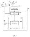
- the system 900 comprises a communications unit 902, a ground-based server 140 and one or more database 150.
- the communications unit 902 is configured for receiving and sending aircraft data 122 from/to one or more aircraft 120.
- the ground-based server 140 comprises a control unit 904.
- the control unit 904 determines the primary identifier 104 of the sector 108 on which the aircraft 120 is located and stores the aircraft data 122 on the database 150.
- the information is stores on a table 152 associated to the sector 108 having said primary identifier 104 and on each of the tables 154 associated to surrounding sectors 110 having a secondary identifier 106 correspondent with said primary identifier 104.
- the communications unit 902 repeatedly transmits to each aircraft 120 the aircraft data stored in the table 152 associated to the sector 108 on which the corresponding aircraft 120 is located.
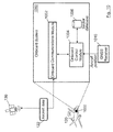
- Figure 10 depicts an embodiment of an onboard system 1000, installed on an aircraft 120, for communicating aircraft data for aircraft surveillance and tracking.
- the onboard system 1000 may be part of the Flight Management System (FMS) or a separate entity.
- the onboard system 1000 comprises an onboard communications module 1002 and an onboard control module 1004.
- the onboard control module 1004 retrieves information about the position of the aircraft 120.
- the onboard control module 1004 obtains the aircraft position (longitude, latitude) from a relevant avionics system (such as GNSS receiver 1010).
- the onboard control module 1004 may also obtain the primary identifier 104 of the sector 108 corresponding to the current aircraft position by accessing a sector database 1006 storing the correspondence between the coordinates of the aircraft (longitude and latitude) and sectors 102.
- the information about the position of the aircraft 120 may comprise the aircraft position (longitude, latitude) and/or the primary identifier 104 of the sector 108 on which the aircraft 120 is located.
- the onboard control module 1004 then generates a header 700 of an IP packet.
- the header 700 comprises a version 710 field with an assigned pre-established value different than the value assigned to IPv4 or IPv6 and a source address 720 field including the retrieved information about the position of the aircraft 120.
- the onboard control module 1004 generates aircraft data 122 comprising at least one IP packet with the previously generated header 700 and sends the generated aircraft data 122 through the onboard communications module 1002.
- the onboard control module 1004 may also receive, originating from the server 140, IP packets with aircraft data corresponding to other aircraft located on the same sector 108 and on the surrounding sectors 110 within the range of interest. For each IP packet received, the onboard control module 1004 checks if the version 710 of the header 700 coincides with the pre-established value, and then extracts the position of all the surrounding aircraft included in the IP packets. Finally, the onboard control module 1004 computes the distance to each individual aircraft. This way the load and data processing of the ground-based server 140 is drastically reduced.
Landscapes
- Engineering & Computer Science (AREA)
- Aviation & Aerospace Engineering (AREA)
- Physics & Mathematics (AREA)
- General Physics & Mathematics (AREA)
- Computer Networks & Wireless Communication (AREA)
- Signal Processing (AREA)
- Multimedia (AREA)
- Traffic Control Systems (AREA)
- Mobile Radio Communication Systems (AREA)
Abstract
Description
- The present disclosure is comprised in the field of surveillance and tracking of aircraft.
- Current air-traffic communication systems, such as primary and secondary radars, multilateration systems and Automatic Dependent Surveillance-Broadcast (ADS-B), present several limitations. First, these communication systems do not provide global coverage. Besides, current communication systems are close to saturation. For instance, ADS-B uses a lot of resources to transmit data to an airplane in an area of interest, rendering the 1090 MHz band close to saturation.
- Furthermore, current communication systems will hardly be able to manage the expected growth of air traffic density for the upcoming years due to the rising number of unmanned aircraft vehicles (UAVs).
- New technologies are arising to deal with the air traffic density growth. One of these emerging technologies is the Internet Protocol (IP)-based communication systems. Internet connectivity available onboard ("Internet onboard") is a new opportunity that provides global coverage. As this type of communication does not use traditional radio links (such as VHF or 1090MHz), but instead satellite link, the range of the system is not limited by the distance between emitter and receiver.
- Through an IP-based communication link, an aircraft sends location data at a rate of twice per second (as current ADS-B). A ground-based server receives the location data, and sends back to the aircraft, information including location data of other airplanes located within a certain distance range. However, in order to determine the information to be sent back to each aircraft, the ground-based server needs to calculate the distance between every pair of airplanes registered. Since there are around twenty thousand concurrent flights, for each cycle (0.5 seconds) the server has to compute around 400 million distances. As these calculations are trigonometry-based, the server performance is overloaded, making the solution difficult to resolve.
- Therefore, there is a need to reduce the big amount of resources needed by the server to determine the information to be sent to each of the aircraft.
- The present disclosure refers to an aircraft surveillance and tracking system and method based on the Internet connectivity available onboard. The aircraft surveillance and tracking platform implements different client applications based on each potential user (aircraft, airline, air traffic control (ATC)) and a server application. The server application is in charge of receiving and distributing the information among the different clients.
- The method of aircraft surveillance and tracking comprises the steps of determining a range of interest, decomposing an airspace region into a plurality of sectors and associating each of the sectors with a primary identifier. For each of the sectors, the surrounding sectors located within the range of interest are obtained.
- The method also comprises the step of further associating each of the sectors with secondary identifiers, wherein the secondary identifiers correspond to the primary identifiers of the surrounding sectors located within the range of interest.
- Upon reception of aircraft data from an aircraft, the following steps are performed: determining the primary identifier of the sector on which the aircraft is located; storing at least part of the aircraft data on a table associated to the sector having said primary identifier; and further storing at least part of the aircraft data on each of the tables associated to surrounding sectors having a secondary identifier correspondent with said primary identifier. Finally, the method comprises sending to one or more aircraft the aircraft data stored in the table associated to the sector on which the corresponding aircraft is located.
- According to an embodiment of the method, the communication with the aircraft is preferably carried out based on Internet Protocol, using IP packets.
- The aircraft data preferably includes information about the aircraft position, which may comprise the primary identifier of the sector on which the aircraft is located and/or the latitude and longitude of the aircraft.
- When the aircraft data includes a header of an IP packet, the information about the aircraft position may be incorporated into the source address field of the header. The source address field of the header preferably further includes a unique identifier.
- In another embodiment, the version field of the header is preferably assigned a pre-established value different than the value assigned to IPv4 or IPv6. Upon reception of aircraft data from an aircraft, the method may comprise a prior step of checking if the version of the header coincides with said pre-established value.
- The method may also comprise the steps of establishing multicast groups taking into account the source address of each aircraft, such that the aircraft belonging to the same multicast group are geographically located in the same sector; and transmitting to the aircraft of each multicast group, through multicast channels, the aircraft data stored in the table associated to the sector of the corresponding multicast group.
- Another aspect of the present disclosure refers to a system of aircraft surveillance and tracking. The airspace region is divided into a plurality of sectors and each sector is associated with a primary identifier and secondary identifiers, wherein the secondary identifiers correspond to the primary identifiers of surrounding sectors located within a range of interest. The system comprises a database, a communications unit for receiving aircraft data from one or more aircraft, and a ground-based server.
- The server comprises a control unit configured to, upon reception of aircraft data from an aircraft, determine the primary identifier of the sector on which the aircraft is located; store at least part of the aircraft data on a table of the database associated to the sector having said primary identifier; and store at least part of the aircraft data on each of the tables of the database associated to surrounding sectors having a secondary identifier correspondent with said primary identifier. Finally, the control unit is configured to send to one or more aircraft, through the communications unit, the aircraft data stored in the table associated to the sector on which the corresponding aircraft is located.
- The control unit of the server may be further configured to send the aircraft data to multicast groups through multicast channels. All the aircraft belonging to the same multicast group are geographically located in the same sector. The aircraft data for each multicast group is stored in the table associated to the sector of the corresponding multicast group.
- A further aspect to the present disclosure refers to a method of communicating aircraft data for aircraft surveillance and tracking, the method comprising the step of generating, in an aircraft, a header of an IP packet by assigning, to the version field of the header, a pre-established value different than the value assigned to IPv4 or IPv6; and incorporating information about the position of the aircraft into the source address field of the header. The method further comprises generating aircraft data comprising at least one IP packet with the previously generated header; and sending, from the aircraft, the generated aircraft data. The information about the position of the aircraft may comprise a primary identifier of the sector on which the aircraft is located and/or the latitude and longitude of the aircraft.
- A further aspect to the present disclosure refers to an onboard system for communicating aircraft data for aircraft surveillance and tracking. The onboard system is installed on an aircraft and comprises an onboard control module configured for retrieving information about the position of the aircraft; generating a header of an IP packet and generating aircraft data comprising at least one IP packet with the previously generated header. The header comprises a version field with an assigned pre-established value different than the value assigned to IPv4 or IPv6; and a source address field including information about the position of the aircraft. The onboard system also comprises a communications module for transmitting the generated aircraft data. The onboard system may also comprise a sector database storing the correspondence between aircraft coordinates and sectors.
- To summarize, the aircraft surveillance and tracking method comprises the following steps:
- An aircraft determines its location (geographical coordinates).
- The aircraft sends these data to a ground-based server.
- The server stores the received information.
- The server sends back to the aircraft the data about the surrounding aircraft (those within a certain range, normally of around 120 nautical miles).
- The server also sends information to other clients according to their need-to-know (e.g. tracking of all the aircraft fleet to a determined airline, or to the aircraft within an area of interest for an Air Traffic Control).
- In order to establish a surveillance system where the information from/to aircraft is transmitted using the onboard available broadband internet connection, it is a priority to minimize the information exchanged between ground-based servers and aircraft, and to optimize the trigonometric calculation processes needed to determine the surrounding air traffic.
- The present invention deals with these two issues. An aircraft autonomously generates a geographically-based network identifier (similar to the IP address) and then, based on this identifier, the aircraft is automatically subscribed to a multicast channel where data of interest (surrounding aircraft, weather reports, etc.) is being transmitted.
- The features, functions, and advantages that have been discussed can be achieved independently in various embodiments or may be combined in yet other embodiments further details of which can be seen with reference to the following description and drawings.
- A series of drawings which aid in better understanding the invention and which are expressly related with an embodiment of said invention, presented as a non-limiting example thereof, are very briefly described below.
-
Figure 1 depicts the airspace sectorization. -
Figure 2 illustrates the primary identifiers assigned to sectors. -
Figure 3 shows the primary and secondary identifiers assigned to each sector. -
Figure 4 depicts the differences in sectors size depending on latitude. -
Figure 5 shows several examples, for different latitudes of a primary sector, of the surrounding sectors within the range of interest of the primary sector. -
Figure 6 shows the storing of aircraft data in the ground-based server. -
Figures 7A and7B depicts two different examples of the header of an IP packet including the aircraft IP address autonomously generated based on its geolocation. -
Figure 8 shows an example of multicast channels and multicast groups. -
Figure 9 depicts a schematic view of an aircraft surveillance and tracking system. -
Figure 10 illustrates an embodiment of an onboard system for communicating aircraft data. - The present disclosure refers to a method and system to optimize the performance of an aircraft surveillance system based on the secure air traffic data transfer through IP channels.
- The aircraft surveillance method can be summarized with the following three steps:
- 1. Airspace sectorization: Split the airspace and implement a database based on that division with multiple tables, each table storing the information of the aircraft within the sector where it is located and the information of the aircraft within the surrounding sectors of interest (sectors within a determined range of interest).
- 2. Provide an identifier to each aircraft based on its location.
- 3. Use multicast techniques to provide each aircraft with the information of the surrounding traffic.
- The information of the surrounding traffic is provided to each aircraft by a ground-based server.
- The first step of the method refers to the airspace sectorization, which includes decomposing an
airspace region 100 into a plurality ofsectors 102 based on the latitude and the longitude, as shown inFigure 1 . The airspace region can be the global airspace region of the Earth or a portion thereof. - The range of current aircraft communication systems is limited by the attenuation of the signal transmitted and the sensitivity of the receiver, according to the following equation:

- Where PRX is the power of the signal received (dBm), PTX is the power of the signal transmitted (dBm), and L is the attenuation suffered by the signal (dB).
- However, when using Internet Protocol (IP) techniques, there is no limitation based on the attenuation of the transmitted signal. A system using such IP techniques will have to deal with the information of each flying aircraft, independently of its location. In order to determine the information of interest to be sent to each of the aircraft, it is necessary to artificially limit the range of the system.
- The present method is based on a sectorization of the
airspace 100, wherein each of thesectors 102 of the grid is associated with a primary identifier 104 (shown inFigure 2 ), based on the latitude and longitude.Figure 2 represents an example of assignment ofprimary identifiers 104 tosectors 102 of theairspace region 100. - The method also assigns secondary identifiers to each of the sectors of the grid, based on the surrounding sectors.
Figure 3 depicts the example ofFigure 2 with primary identifiers 104 (in the middle of each sector) and secondary identifiers 106 (in the periphery of each sector) assigned to eachsector 102. - The purpose of the
secondary identifiers 106 is to artificially establish the area or range of interest of each aircraft. As the surface of the sectors vary based on the latitude and longitude, in order to establish a range of interest (e.g. 120 nautical miles) not all thesectors 102 have the same number ofsecondary identifiers 106. -
Figure 4 depicts the different size of thesectors 102 depending on latitude. Near the poles thesectors 102a are smaller; however, next to the equator thesectors 102b are much larger. Therefore, an aircraft flying in a givensector 102a near the poles will need a larger number of surrounding sectors in order to obtain from the server the air traffic in the range of interest. On the contrary, an aircraft flying in a givensector 102b near the equator will need a smaller number of surrounding sectors to obtain from the server the air traffic in the same range of interest, which is normally set to around 120 nautical miles. -
Figure 5 shows several examples of different number of surroundingsectors 110 within the range of interest of aprimary sector 108 where the aircraft (marked with a triangle) is located. In order to establish a determined range of interest to cover, the number of surroundingsectors 110 of interest depends on the location of the aircraft, and more particularly on the latitude of theprimary sector 108 where the aircraft is located. As shown inFigure 5 the number of surroundingsectors 110 within the range of interest is much larger when the primary sector is located near the pole. - Therefore, as represented in
Figure 3 , eachsector 102 has associated a primary identifier 104 (which is unique and may be based on the longitude and latitude of the sector) and a plurality ofsecondary identifiers 106 to cover a range of interest (120 nautical miles for a system equivalent to ADS-B). The method comprises determining, for each of thesectors 102, the surroundingsectors 110 located within the range of interest. The method further comprises associating each of thesectors 102 with thesecondary identifiers 106. Thesecondary identifiers 106 correspond to theprimary identifiers 104 of the surroundingsectors 110 located within the range of interest to thecorresponding sector 102. -
Figure 6 shows the storing of information in adatabase 150 of a ground-basedserver 140. Anaircraft 120 determines its position using instruments onboard (e.g. geographical coordinates obtained by a global navigation satellite system (GNSS) receiver). Theaircraft 120 sendsdata 122 including an aircraft identifier and the aircraft position using the internet connection onboard through asatellite 130. - The
server 140 receives the aircraft data and, based on the aircraft location, records the information in adatabase 150. Theserver 140 obtains, using the aircraft position, thesector 102 on which the aircraft is currently located. Alternatively, the aircraft data may include information with thesector 108 on which theaircraft 120 is located, obtained by theaircraft 120 using a correlating table. - The
server 140 stores the aircraft data in a table 152 correspondent with thesector 108 where theaircraft 120 is located, sector with primary identifier (1,1) in the example ofFigure 6 . Moreover, the aircraft data is also stored in the tables 154 correspondent with the surroundingsectors 110 located within the range of interest, in the example ofFigure 6 the surrounding sectors are those with secondary identifier (1,1). - Therefore, the
database 150 stores the information in one table per sector, each table being associated with theprimary identifier 104. When information from anaircraft 120 is received, the data is stored not only in the table 152 associated to thesector 108 where the aircraft is located, but also in the tables 154 associated to the surroundingsectors 110 within the range of interest, the surroundingsectors 110 having asecondary identifier 106 equal to theprimary identifier 104 of thesector 108 where theaircraft 120 is located. In the case represented inFigure 6 , the data is stored in the table 152 with primary identifier (1,1) and in the tables 154 of the surroundingsectors 110 having the secondary identifier (1,1). - The method also comprises providing an aircraft identifier to each aircraft. In the present IP-based communication, aircraft IP address is autonomously and dynamically generated based on geolocation.
- The
header 700 of an IP packet, as depicted in the examples ofFigures 7A and7B , includes the following customized fields: - Version 710: The first header field in an IP packet is the four-bit version field. This field is used to indicate the format of the IP header (e.g. for IPv4, this has a value of 4). Any available value (such as a value of 10) may be used for this field to indicate that the format of the IP packet is the one used in the present IP-based protocol. Knowing the IP protocol used, the receiver will be able to interpret the customized fields of the IP packets.
- Source address 720: This field is the address of the sender of the IP packet. According to a first embodiment of the IP-based protocol shown in
Figure 7A , the source address field contains the following data:- Bits 0 - 8: The integer value of the
current longitude 724 of theaircraft 120 is coded in the first nine bits. It may include longitude values within [-180, 180]. - Bits 9 - 16: The integer value of the
current latitude 726 of theaircraft 120 is included in the following eight bits. It may include latitude values within [-90, 90]. - Bits 17 - 31: A randomly generated value,
unique identifier 728, is included here. It helps to establish a unique source IP address. A new value may be generated when thelongitude 724 and/or thelatitude 726 change.
- Bits 0 - 8: The integer value of the
- According to another embodiment, shown in
Figure 7B , instead of including thelongitude 724 andlatitude 726 of theaircraft 120, thesource address 720 may include a prefix orfirst sub-field 722 with theprimary identifier 104 of thecurrent sector 108 where theaircraft 120 is located, along with theunique identifier 728. Alternatively, as shown below, thesource address 720 may include afirst sub-field 722 with theprimary identifier 104 of thesector 108 where theaircraft 120 is located, in addition to thelongitude 724 andlatitude 726 of theaircraft 120 and theunique identifier 728. To obtain the content of thefirst sub-field 722, a control module installed onboard may access a local database to retrieve theprimary identifier 104 of thesector 108 corresponding to the current position (longitude and latitude) of theaircraft 120. - In the embodiments of
Figures 7A and7B different sizes in bits for the sub-fields of the source address 720 (primary identifier 722,longitude 724,latitude 726, unique identifier 728) may be envisaged. - This IP-based protocol enables the ground-based
server 140, by analyzing thesource address field 720 of theIP header 700 received, to determine where (i.e. in which tables) to store the information sent by eachaircraft 120. - The
IP header 700 also allows grouping the surrounding aircraft by IP address. In the embodiments ofFigure 7B , all of the aircraft within the same sector will share the first sub-field 722 (containing theprimary identifier 104 of the current sector 108) of thesource address 720. For the embodiment ofFigure 7A , if thesectors 102 are defined with a size of 1° latitude x 1° longitude, every aircraft within the same sector will share the first two sub-fields (724,726) of thesource address 720. This feature is extremely useful to determine multicast groups. - According to the embodiment of
Figure 8 , the information received by theserver 140 may be distributed back to theaircraft 120 by means of multicast groups (800a, 800b). Multicasting groups (800a, 800b) are established taking into account the IP address of the aircraft. All of theaircraft 120 within the same sector (108a, 108b) share thefirst sub-field 722 of thesource address 720 according to the embodiment ofFigure 7B (or the first 17 bits corresponding to thelongitude 724 andlatitude 726 in the embodiment ofFigure 7A ), and will therefore receive the same information each cycle. This feature drastically reduces the calculations to be performed by theserver 140, as well as the number of IP packets to be sent. - All of the
aircraft 120 belonging to the same multicast group (800a, 800b) are geographically located in the same sector (108a, 108b). Each multicast group (800a, 800b) corresponds to a different sector (108a, 108b). Different multicast channels (802a, 802b) are established to distribute the information stored in the table (152a, 152b) of thedatabase 150 corresponding to the sector (108a, 108b) of the multicast group (800a, 800b). - Information is sent to the aircraft using the internet connection onboard. Each aircraft receives only the information of interest associated to the sector on which the aircraft is located, the being data sent through the multicast channel the aircraft belongs to.
- This way, the
server 140 acts as a first filter of the information. In the example ofFigure 8 , all of theaircraft 120 flying in afirst sector 108a, sector (1,1), will receive the same data, the information stored in the table 152a associated to the sector (1,1), having as primary identifier (1,1), thus including the aircraft data 122 (e.g. aircraft identifier and aircraft position) of all aircraft flying in sectors {(0,0), (0,1), (0,2), (1,0), (1,1), (1,2), (2,0), (2,1), (2,2)}. Similarly, theserver 140 sends the same data to all theaircraft 120 flying in asecond sector 108b, sector (2,1): the information stored in the table 152b associated to the sector (2,1), having as primary identifier (2,1), and therefore including theaircraft data 122 of all the airplanes flying in sectors {(1,0), (1,1), (1,2), (2,0), (2,1), (2,2), (3,0), (3,1), (3,2)}. - Once an
aircraft 120 receives from theserver 140 the identifier and position of the airplanes flying in its sector (108) and the surrounding sectors (110) within the range of interest, saidaircraft 120 then computes the distance to all these airplanes. Trigonometric calculations are therefore performed by the client, theaircraft 120, over a very limited number of airplanes (only over those within a determined range). Therefore, trigonometric calculations performed by theserver 140 are greatly reduced, optimizing the performance and avoiding saturation of theserver 140. - An embodiment of an aircraft surveillance and
tracking system 900, implementing the method previously described, is depicted inFigure 9 . Thesystem 900 comprises acommunications unit 902, a ground-basedserver 140 and one ormore database 150. Thecommunications unit 902 is configured for receiving and sendingaircraft data 122 from/to one ormore aircraft 120. - The ground-based
server 140 comprises acontrol unit 904. Whenaircraft data 122 from anaircraft 120 is received, thecontrol unit 904 determines theprimary identifier 104 of thesector 108 on which theaircraft 120 is located and stores theaircraft data 122 on thedatabase 150. In particular, the information is stores on a table 152 associated to thesector 108 having saidprimary identifier 104 and on each of the tables 154 associated to surroundingsectors 110 having asecondary identifier 106 correspondent with saidprimary identifier 104. - The
communications unit 902 repeatedly transmits to eachaircraft 120 the aircraft data stored in the table 152 associated to thesector 108 on which thecorresponding aircraft 120 is located. -
Figure 10 depicts an embodiment of anonboard system 1000, installed on anaircraft 120, for communicating aircraft data for aircraft surveillance and tracking. Theonboard system 1000 may be part of the Flight Management System (FMS) or a separate entity. Theonboard system 1000 comprises anonboard communications module 1002 and anonboard control module 1004. - The
onboard control module 1004 retrieves information about the position of theaircraft 120. In particular, theonboard control module 1004 obtains the aircraft position (longitude, latitude) from a relevant avionics system (such as GNSS receiver 1010). Theonboard control module 1004 may also obtain theprimary identifier 104 of thesector 108 corresponding to the current aircraft position by accessing asector database 1006 storing the correspondence between the coordinates of the aircraft (longitude and latitude) andsectors 102. The information about the position of theaircraft 120 may comprise the aircraft position (longitude, latitude) and/or theprimary identifier 104 of thesector 108 on which theaircraft 120 is located. - The
onboard control module 1004 then generates aheader 700 of an IP packet. Theheader 700 comprises aversion 710 field with an assigned pre-established value different than the value assigned to IPv4 or IPv6 and asource address 720 field including the retrieved information about the position of theaircraft 120. Theonboard control module 1004 generatesaircraft data 122 comprising at least one IP packet with the previously generatedheader 700 and sends the generatedaircraft data 122 through theonboard communications module 1002. - The
onboard control module 1004 may also receive, originating from theserver 140, IP packets with aircraft data corresponding to other aircraft located on thesame sector 108 and on the surroundingsectors 110 within the range of interest. For each IP packet received, theonboard control module 1004 checks if theversion 710 of theheader 700 coincides with the pre-established value, and then extracts the position of all the surrounding aircraft included in the IP packets. Finally, theonboard control module 1004 computes the distance to each individual aircraft. This way the load and data processing of the ground-basedserver 140 is drastically reduced.
Claims (15)
- A method of aircraft surveillance and tracking, comprising:- determining a range of interest;- decomposing an airspace region (100) into a plurality of sectors (102);- associating each of the sectors with a primary identifier (104);- for each of the sectors (102), determining surrounding sectors (110) located within a range of interest;- further associating each of the sectors (102) with secondary identifiers (106), wherein the secondary identifiers (106) correspond to the primary identifiers (104) of the surrounding sectors (110) located within the range of interest;- upon reception of aircraft data (122) from an aircraft (120):determining the primary identifier (104) of a sector (108) on which the aircraft (120) is located;storing at least part of the aircraft data (122) on a table (152) associated to the sector (108) having said primary identifier (104);further storing at least part of the aircraft data (122) on each of the tables (154) associated to the surrounding sectors (110) having a secondary identifier (106) correspondent with said primary identifier (104);- sending to one or more aircraft (120) the aircraft data stored in the table (152) associated to the sector (108) on which a corresponding aircraft (120) is located.
- The method of claim 1, wherein communication with the aircraft (120) is based on Internet Protocol.
- The method of claim 1 or 2, wherein the aircraft data (122) includes information about a position of the aircraft.
- The method of claim 3, wherein the information about the aircraft position comprises the primary identifier (104) of the sector (108) on which the aircraft (120) is located.
- The method of claim 3 or 4, wherein the information about the aircraft position comprises the latitude (724) and longitude (726) of the aircraft (120).
- The method of any of claims 3 to 5, wherein the aircraft data (122) comprises a header (700) of an IP packet, and wherein the information about the aircraft position is included in a source address (720) field of the header (700).
- The method of claim 6, wherein the source address (720) field of the header (700) further includes a unique identifier (728).
- The method of any of claims 6 to 7, wherein the version (710) field of the header (700) is assigned a pre-established value different than the value assigned to IPv4 or IPv6, and wherein the method comprises, upon reception of aircraft data (122) from an aircraft (120), a prior step of checking if the version (710) of the header (700) coincides with said pre-established value.
- The method of any of claims 6 to 8, further comprising:establishing multicast groups (800a, 800b) taking into account the source address (720) of each aircraft (120), such that the aircraft (120) belonging to the same multicast group (800a, 800b) are geographically located in the same sector (108a, 108b);transmitting to the aircraft (120) of each multicast group (800a, 800b), through multicast channels (802a, 802b), the aircraft data (122) stored in the table (152a, 152b) associated to the sector (108a, 108b) of the corresponding multicast group (800a, 800b).
- A system of aircraft surveillance and tracking, wherein the airspace region (100) is divided into a plurality of sectors (102), each sector (102) being associated with a primary identifier (104) and secondary identifiers (106), wherein the secondary identifiers (106) correspond to the primary identifiers (104) of surrounding sectors (110) located within a range of interest; the system (900) comprising:- a database (150);- a communications unit (902) configured for receiving aircraft data (122) from one or more aircraft (120);- a ground-based server (140) with a control unit (904) configured for:upon reception of aircraft data (122) from an aircraft (120):• determining the primary identifier (104) of the sector (108) on which the aircraft (120) is located;• storing at least part of the aircraft data (122) on a table (152) of the database (150) associated to the sector (108) having said primary identifier (104);• further storing at least part of the aircraft data (122) on each of the tables (154) of the database (150) associated to surrounding sectors (110) having a secondary identifier (106) correspondent with said primary identifier (104);• sending to one or more aircraft (120), through the communications unit (902), the aircraft data stored in the table (152) associated to the sector (108) on which the corresponding aircraft (120) is located.
- A system of claim 10, wherein the communication with the aircraft (120) is based on Internet Protocol.
- The system of claim 11, wherein the control unit (904) is configured to send the aircraft data to multicast groups (800a, 800b) through multicast channels (802a, 802b), wherein all the aircraft (120) belonging to the same multicast group (800a, 800b) are geographically located in the same sector (108a, 108b),
and wherein the aircraft data for each multicast group (800a, 800b) is stored in the table (152a, 152b) associated to the sector (108a, 108b) of the corresponding multicast group (800a, 800b). - A method of communicating aircraft data for aircraft surveillance and tracking, the method comprising:- generating, in an aircraft (120), a header (700) of an IP packet by:assigning, to a version (710) field of the header (700), a pre-established value different than a value assigned to IPv4 or IPv6;incorporating information about the position of the aircraft (120) into the source address (720) field of the header (700);- generating aircraft data (122) comprising at least one IP packet with the previously generated header (700);- sending, from the aircraft (120), the generated aircraft data (122).
- The method of claim 13, wherein the information about the position of the aircraft (120) comprises at least one of:a primary identifier (104) of the sector (108) on which the aircraft (120) is located;the latitude (724) and longitude (726) of the aircraft (120).
- An onboard system for communicating aircraft data for aircraft surveillance and tracking, the onboard system (1000) being installed on an aircraft (120) and comprising:- an onboard control module (1004) configured for:retrieving information about the position of the aircraft;generating a header (700) of an IP packet, the header (700) comprising:a version (710) field with an assigned pre-established value different than a value assigned to IPv4 or IPv6;a source address (720) field including information about the position of the aircraft (120);generating aircraft data (122) comprising at least one IP packet with the previously generated header (700);- an onboard communications module (1002) configured for transmitting the generated aircraft data (122).
Priority Applications (2)
| Application Number | Priority Date | Filing Date | Title |
|---|---|---|---|
| EP16382356.0A EP3273424B1 (en) | 2016-07-21 | 2016-07-21 | System and method of aircraft surveillance and tracking |
| US15/587,089 US10542381B2 (en) | 2016-07-21 | 2017-05-04 | System and method of aircraft surveillance and tracking |
Applications Claiming Priority (1)
| Application Number | Priority Date | Filing Date | Title |
|---|---|---|---|
| EP16382356.0A EP3273424B1 (en) | 2016-07-21 | 2016-07-21 | System and method of aircraft surveillance and tracking |
Publications (2)
| Publication Number | Publication Date |
|---|---|
| EP3273424A1 true EP3273424A1 (en) | 2018-01-24 |
| EP3273424B1 EP3273424B1 (en) | 2019-03-13 |
Family
ID=56787395
Family Applications (1)
| Application Number | Title | Priority Date | Filing Date |
|---|---|---|---|
| EP16382356.0A Active EP3273424B1 (en) | 2016-07-21 | 2016-07-21 | System and method of aircraft surveillance and tracking |
Country Status (2)
| Country | Link |
|---|---|
| US (1) | US10542381B2 (en) |
| EP (1) | EP3273424B1 (en) |
Families Citing this family (6)
| Publication number | Priority date | Publication date | Assignee | Title |
|---|---|---|---|---|
| EP3273424B1 (en) * | 2016-07-21 | 2019-03-13 | The Boeing Company | System and method of aircraft surveillance and tracking |
| US10347136B2 (en) * | 2016-12-23 | 2019-07-09 | Wing Aviation Llc | Air traffic communication |
| US10977954B2 (en) * | 2018-04-27 | 2021-04-13 | Seamatica Aerospace Ltd. | Method and system for communicating unicast/multicast messages using automatic dependent surveillance—broadcast (ADS-B) protocol |
| US12014643B2 (en) * | 2018-04-27 | 2024-06-18 | Seamatica Aerospace Ltd. | Method and system for communicating unicast/multicast messages using automatic dependent surveillance-broadcast (ADS-B) protocol |
| US11388587B2 (en) * | 2018-06-04 | 2022-07-12 | Smartsky Networks, Llc | Contextually aware, smart IP address |
| EP4165799B1 (en) * | 2021-09-03 | 2023-08-02 | Flarm Technology AG | Aircraft collision avoidance method and device |
Citations (6)
| Publication number | Priority date | Publication date | Assignee | Title |
|---|---|---|---|---|
| US6275771B1 (en) * | 1999-01-28 | 2001-08-14 | International Business Machines Corporation | Time multiplexed global positioning system cell location beacon system |
| US20070162197A1 (en) * | 2006-01-12 | 2007-07-12 | Global Aerospace, Llc | Airplane system for an atmospheric turbulence analysis system |
| US20080004792A1 (en) * | 2006-06-29 | 2008-01-03 | Gerald Bowden Wise | Air traffic demand prediction |
| US20120303253A1 (en) * | 2009-09-21 | 2012-11-29 | Nats (En Route) Public Limited Company | Air traffic control |
| US20130126679A1 (en) * | 2011-11-23 | 2013-05-23 | Regina I. Estkowski | System and methods for situation awareness, advisory, tracking, and aircraft control information |
| US9310477B1 (en) * | 2013-01-29 | 2016-04-12 | The Boeing Company | Systems and methods for monitoring airborne objects |
Family Cites Families (61)
| Publication number | Priority date | Publication date | Assignee | Title |
|---|---|---|---|---|
| US6195609B1 (en) * | 1993-09-07 | 2001-02-27 | Harold Robert Pilley | Method and system for the control and management of an airport |
| US6133867A (en) * | 1998-01-02 | 2000-10-17 | Eberwine; David Brent | Integrated air traffic management and collision avoidance system |
| US6243647B1 (en) * | 1999-01-28 | 2001-06-05 | International Business Machines Corporation | Three dimensional display for time multiplexed global positioning system cell location beacon system |
| US8078163B2 (en) * | 2000-10-11 | 2011-12-13 | Gogo Llc | System for customizing electronic content for delivery to a passenger in an airborne wireless cellular network |
| JP2002176432A (en) * | 2000-12-05 | 2002-06-21 | Sony Corp | Communication relay device, communication relay method, communication terminal device, and program storage medium |
| DE10217222A1 (en) * | 2002-04-18 | 2003-11-06 | Diehl Avionik Systeme Gmbh | Aircraft security system |
| US7272148B2 (en) * | 2002-06-27 | 2007-09-18 | Hewlett-Packard Development Company, L.P. | Non-ALG approach for application layer session traversal of IPv6/IPv4 NAT-PT gateway |
| JP4076071B2 (en) * | 2002-08-19 | 2008-04-16 | アルパイン株式会社 | Communication method and vehicle communication apparatus between moving bodies |
| US20040098479A1 (en) * | 2002-10-25 | 2004-05-20 | General Instrument Corporation | Method for using different packet type and port options values in an IP measurement protocol packet from those used to process the packet |
| JP2004221745A (en) * | 2003-01-10 | 2004-08-05 | Fujitsu Ltd | Address translator |
| CA2444827C (en) * | 2003-10-10 | 2011-11-29 | Nav Canada | Database architecture for an air traffic information system |
| US7330726B2 (en) * | 2004-06-07 | 2008-02-12 | Spyder Navigation Llc | Determining geographical position in IPv6 networks |
| US7194353B1 (en) * | 2004-12-03 | 2007-03-20 | Gestalt, Llc | Method and system for route planning of aircraft using rule-based expert system and threat assessment |
| US20070022479A1 (en) * | 2005-07-21 | 2007-01-25 | Somsubhra Sikdar | Network interface and firewall device |
| US8660526B1 (en) * | 2005-06-24 | 2014-02-25 | Rockwell Collins, Inc. | Location-based intrusion detection system |
| US7708493B2 (en) * | 2005-08-26 | 2010-05-04 | Searete, Llc | Modifiable display marker |
| US9419955B2 (en) * | 2006-03-28 | 2016-08-16 | Inventergy Inc. | System and method for carrying trusted network provided access network information in session initiation protocol |
| US7605688B1 (en) * | 2006-05-19 | 2009-10-20 | Rockwell Collins, Inc. | Vehicle location determination system using an RFID system |
| US20130150004A1 (en) * | 2006-08-11 | 2013-06-13 | Michael Rosen | Method and apparatus for reducing mobile phone usage while driving |
| US8314736B2 (en) * | 2008-03-31 | 2012-11-20 | Golba Llc | Determining the position of a mobile device using the characteristics of received signals and a reference database |
| CN101247317B (en) * | 2007-02-15 | 2011-07-20 | 华为技术有限公司 | Routing switching method and system |
| US8355864B2 (en) * | 2007-03-27 | 2013-01-15 | Nec Corporation | Map matching system, map matching method and program |
| US8811265B2 (en) * | 2007-10-19 | 2014-08-19 | Honeywell International Inc. | Ad-hoc secure communication networking based on formation flight technology |
| WO2009059618A1 (en) * | 2007-11-07 | 2009-05-14 | Panasonic Corporation | Mobile ip route optimization in ip version transition scenarios |
| US20090147759A1 (en) * | 2007-12-10 | 2009-06-11 | Electronics & Telecommunications Research Institute | Method and apparatus for supporting mobility of node using layer 2/layer 3 addresses |
| JP4600513B2 (en) * | 2008-04-25 | 2010-12-15 | ソニー株式会社 | Data transmission apparatus, transmission rate control method, and program |
| JP5332854B2 (en) * | 2009-04-20 | 2013-11-06 | ソニー株式会社 | Wireless transmitter, wireless transmission method, wireless receiver, and wireless reception method |
| CN102577458B (en) * | 2009-08-12 | 2016-07-06 | 黑莓有限公司 | Adapt to mixed IPV4V6 network support |
| US8188907B2 (en) * | 2009-09-12 | 2012-05-29 | International Business Machines Corporation | Aircraft collision avoidance alarm |
| CN102025606B (en) * | 2009-09-23 | 2012-12-19 | 中兴通讯股份有限公司 | Data transmission method and system |
| US8811616B2 (en) * | 2010-04-12 | 2014-08-19 | Flight Focus Pte. Ltd. | Secure aircraft data channel communication for aircraft operations |
| US9461996B2 (en) * | 2010-05-07 | 2016-10-04 | Citrix Systems, Inc. | Systems and methods for providing a single click access to enterprise, SAAS and cloud hosted application |
| US9143738B2 (en) * | 2010-06-22 | 2015-09-22 | Livetv, Llc | Aircraft IFE system interfacing with a personal electronic device (PED) for redeeming an in-flight coupon and associated methods |
| US20120047572A1 (en) * | 2010-08-17 | 2012-02-23 | Richard Jeremy Duncan | Decapsulation of data packet tunnels to process encapsulated ipv4 or ipv6 packets |
| WO2012137044A1 (en) * | 2011-04-07 | 2012-10-11 | Telefonaktiebolaget L M Ericsson (Publ) | Ethernet based local ip access |
| US8612530B1 (en) * | 2011-05-27 | 2013-12-17 | Mu Dynamics, Inc. | Pass-through testing using message exchange identifiers |
| US9225633B2 (en) * | 2011-10-31 | 2015-12-29 | At&T Intellectual Property I, L.P. | Methods, apparatus, and articles of manufacture to provide a multicast virtual private network (MVPN) |
| US20130124089A1 (en) * | 2011-11-11 | 2013-05-16 | Lockheed Martin Corporation | Spatiotemporal survivability data compression using objective oriented constraints |
| US9408177B2 (en) * | 2011-12-19 | 2016-08-02 | Cisco Technology, Inc. | System and method for resource management for operator services and internet |
| US20130157611A1 (en) * | 2011-12-20 | 2013-06-20 | Eric Small | Mobile cellular node method and apparatus for emergency relief and rescue |
| US8971932B2 (en) * | 2011-12-24 | 2015-03-03 | Secure Sigint, LLC | Secure witness or criminal participant location or position and time recording information apparatus, systemts and methods |
| KR20170013417A (en) * | 2012-03-02 | 2017-02-06 | 인터디지탈 패튼 홀딩스, 인크 | Method and system for providing beacon information |
| EP4683387A3 (en) * | 2012-07-03 | 2026-04-01 | InterDigital Patent Holdings, Inc. | Fast initial link setup discovery frames |
| US10212076B1 (en) * | 2012-12-27 | 2019-02-19 | Sitting Man, Llc | Routing methods, systems, and computer program products for mapping a node-scope specific identifier |
| US20140189156A1 (en) * | 2012-12-27 | 2014-07-03 | Deep River Ventures, Llc | Methods, Systems, and Computer Program Products for Routing Based on a Path-Based Protocol Address |
| US9674649B2 (en) * | 2013-01-14 | 2017-06-06 | Qualcomm Incorporated | Methods and apparatus for providing location information with private expressions |
| JP2015050758A (en) * | 2013-09-05 | 2015-03-16 | 株式会社日立製作所 | Radio communication system, radio communication method, and base station |
| US10102755B1 (en) * | 2013-10-07 | 2018-10-16 | Satcom Direct, Inc. | Method and system for aircraft positioning—automated tracking using onboard global voice and high-speed data |
| US9718557B2 (en) * | 2014-01-17 | 2017-08-01 | The Research Foundation For The State University Of New York | Flight data tracker |
| WO2015106346A1 (en) * | 2014-01-20 | 2015-07-23 | Skytrac Systems Ltd. | Method and system for tracking distance travelled by aircraft |
| WO2016057098A2 (en) * | 2014-07-15 | 2016-04-14 | Richard Postrel | System and method for automated traffic management of intelligent unmanned aerial vehicles |
| WO2016019543A1 (en) * | 2014-08-07 | 2016-02-11 | 华为技术有限公司 | Method and apparatus for reporting location information of user equipment |
| EP2985926B1 (en) * | 2014-08-12 | 2017-06-07 | Airbus Operations GmbH | Radio aircraft network with an operator station storing aircraft and ground-based stations locations and establishing a path between the aircraft and the ground stations based on the locations. |
| EP3088911B1 (en) * | 2015-04-20 | 2019-03-13 | The Boeing Company | A method of communicating airborne multilateration information |
| US9922571B1 (en) * | 2015-05-08 | 2018-03-20 | Rockwell Collins, Inc. | Virtual ADS-B for small aircraft |
| EP3340717B1 (en) * | 2015-08-17 | 2021-06-09 | LG Electronics Inc. | Method for transmitting and receiving packets in wireless communication system, and apparatus therefor |
| US10075810B2 (en) * | 2015-10-30 | 2018-09-11 | Qualcomm Incorporated | Techniques for wide area network based vehicle-to-vehicle signaling |
| EP3338059A4 (en) * | 2015-11-10 | 2019-04-10 | Thales Defense & Security Inc. | SEMI-AUTOMATIC DRONE FOR VERIFICATION OF AVIONIC NAVIGATION SIGNALS AND METHODS OF OPERATION THEREOF AND USE THEREOF |
| US9793978B2 (en) * | 2016-01-22 | 2017-10-17 | Honeywell International Inc. | Efficient aeronautical information download coupled with ADS-B function |
| WO2017171923A1 (en) * | 2016-04-01 | 2017-10-05 | Intel Corporation | V2x communication configuration based on geographical location |
| EP3273424B1 (en) * | 2016-07-21 | 2019-03-13 | The Boeing Company | System and method of aircraft surveillance and tracking |
-
2016
- 2016-07-21 EP EP16382356.0A patent/EP3273424B1/en active Active
-
2017
- 2017-05-04 US US15/587,089 patent/US10542381B2/en active Active
Patent Citations (6)
| Publication number | Priority date | Publication date | Assignee | Title |
|---|---|---|---|---|
| US6275771B1 (en) * | 1999-01-28 | 2001-08-14 | International Business Machines Corporation | Time multiplexed global positioning system cell location beacon system |
| US20070162197A1 (en) * | 2006-01-12 | 2007-07-12 | Global Aerospace, Llc | Airplane system for an atmospheric turbulence analysis system |
| US20080004792A1 (en) * | 2006-06-29 | 2008-01-03 | Gerald Bowden Wise | Air traffic demand prediction |
| US20120303253A1 (en) * | 2009-09-21 | 2012-11-29 | Nats (En Route) Public Limited Company | Air traffic control |
| US20130126679A1 (en) * | 2011-11-23 | 2013-05-23 | Regina I. Estkowski | System and methods for situation awareness, advisory, tracking, and aircraft control information |
| US9310477B1 (en) * | 2013-01-29 | 2016-04-12 | The Boeing Company | Systems and methods for monitoring airborne objects |
Also Published As
| Publication number | Publication date |
|---|---|
| EP3273424B1 (en) | 2019-03-13 |
| US20180027382A1 (en) | 2018-01-25 |
| US10542381B2 (en) | 2020-01-21 |
Similar Documents
| Publication | Publication Date | Title |
|---|---|---|
| EP3273424B1 (en) | System and method of aircraft surveillance and tracking | |
| US11424817B2 (en) | Enhanced LDACS system having mesh network topology and associated methods | |
| US20220317290A1 (en) | Enhanced ldacs that uses doppler shifts in carrier signals for positioning and navigation | |
| US10650688B1 (en) | Air traffic situational awareness using HF communication | |
| US10453347B2 (en) | Method and systems for increasing capacity and safety of aeronautical safety-of-life services and data links | |
| US10531505B2 (en) | Communicating with unmanned aerial vehicles and air traffic control | |
| EP2980775B1 (en) | Remote air traffic surveillance data compositing based on datalinked radio surveillance | |
| US20030158963A1 (en) | Smartbridge for tactical network routing applications | |
| Ertürk et al. | Requirements and technologies towards uam: Communication, navigation, and surveillance | |
| Garcia et al. | Aireon space based ADS-B performance model | |
| US10362531B2 (en) | Systems and methods for enhanced subnetwork preference logic | |
| Fuger et al. | Modeling of communication requirements for distributed utm using stochastic geometry | |
| Medina et al. | Topology characterization of high density airspace aeronautical ad hoc networks | |
| Ponchak et al. | An implementation analysis of communications, navigation, and surveillance (CNS) technologies for unmanned air systems (UAS) | |
| NZ532853A (en) | Selection of one among several networks for data transmissions by creating interface between civil and military communication systems | |
| CN105842709A (en) | Aerial monitoring system and method thereof | |
| Ponchak et al. | Advancing the Standards for Unmanned Air System Communications, Navigation and Surveillance | |
| Leonardo et al. | VHF Data Link communications to provide air traffic services in Colombia | |
| US11259193B2 (en) | Systems and methods for obtaining and distributing dynamic frequency selection data for wireless networks on airplanes | |
| Yeniçeri et al. | Enabling Centralized UTM services through cellular network for VLL UAVs | |
| CN119233291B (en) | Traffic distribution determination method, device, equipment, storage medium and program product | |
| Donovan | Concept for an integrated national surveillance and data communication infrastructure | |
| Gomez et al. | Implementation of automatic dependent surveillance (ADS-B) in Colombia | |
| EP1435155A2 (en) | Selection of one among several networks for data transmissions | |
| Gupta | A product development decision model for cockpit weather information systems |
Legal Events
| Date | Code | Title | Description |
|---|---|---|---|
| STAA | Information on the status of an ep patent application or granted ep patent |
Free format text: STATUS: EXAMINATION IS IN PROGRESS |
|
| PUAI | Public reference made under article 153(3) epc to a published international application that has entered the european phase |
Free format text: ORIGINAL CODE: 0009012 |
|
| 17P | Request for examination filed |
Effective date: 20160721 |
|
| AK | Designated contracting states |
Kind code of ref document: A1 Designated state(s): AL AT BE BG CH CY CZ DE DK EE ES FI FR GB GR HR HU IE IS IT LI LT LU LV MC MK MT NL NO PL PT RO RS SE SI SK SM TR |
|
| AX | Request for extension of the european patent |
Extension state: BA ME |
|
| RIC1 | Information provided on ipc code assigned before grant |
Ipc: G06F 3/00 20060101ALI20180222BHEP Ipc: G06F 12/00 20060101ALI20180222BHEP Ipc: H04W 4/06 20090101ALI20180222BHEP Ipc: G08G 5/00 20060101ALI20180222BHEP Ipc: H04W 84/06 20090101ALI20180222BHEP Ipc: H04W 4/021 20180101AFI20180222BHEP Ipc: H04W 4/08 20090101ALI20180222BHEP Ipc: H04W 4/029 20180101ALI20180222BHEP |
|
| GRAP | Despatch of communication of intention to grant a patent |
Free format text: ORIGINAL CODE: EPIDOSNIGR1 |
|
| STAA | Information on the status of an ep patent application or granted ep patent |
Free format text: STATUS: GRANT OF PATENT IS INTENDED |
|
| RIC1 | Information provided on ipc code assigned before grant |
Ipc: G08G 5/00 20060101ALI20181030BHEP Ipc: G06F 12/00 20060101ALI20181030BHEP Ipc: H04W 4/08 20090101ALI20181030BHEP Ipc: G06F 3/00 20060101ALI20181030BHEP Ipc: H04W 84/06 20090101ALI20181030BHEP Ipc: H04W 4/029 20180101ALI20181030BHEP Ipc: H04W 4/021 20180101AFI20181030BHEP Ipc: G06F 17/30 20060101ALI20181030BHEP Ipc: H04W 4/06 20090101ALI20181030BHEP |
|
| INTG | Intention to grant announced |
Effective date: 20181122 |
|
| GRAJ | Information related to disapproval of communication of intention to grant by the applicant or resumption of examination proceedings by the epo deleted |
Free format text: ORIGINAL CODE: EPIDOSDIGR1 |
|
| STAA | Information on the status of an ep patent application or granted ep patent |
Free format text: STATUS: EXAMINATION IS IN PROGRESS |
|
| REG | Reference to a national code |
Ref country code: DE Ref legal event code: R079 Ref document number: 602016011003 Country of ref document: DE Free format text: PREVIOUS MAIN CLASS: G08G0005000000 Ipc: G06F0016000000 |
|
| GRAR | Information related to intention to grant a patent recorded |
Free format text: ORIGINAL CODE: EPIDOSNIGR71 |
|
| GRAS | Grant fee paid |
Free format text: ORIGINAL CODE: EPIDOSNIGR3 |
|
| STAA | Information on the status of an ep patent application or granted ep patent |
Free format text: STATUS: GRANT OF PATENT IS INTENDED |
|
| GRAA | (expected) grant |
Free format text: ORIGINAL CODE: 0009210 |
|
| STAA | Information on the status of an ep patent application or granted ep patent |
Free format text: STATUS: THE PATENT HAS BEEN GRANTED |
|
| INTC | Intention to grant announced (deleted) | ||
| RIC1 | Information provided on ipc code assigned before grant |
Ipc: H04W 4/029 20180101ALI20190115BHEP Ipc: G06F 16/00 20190101AFI20190115BHEP Ipc: G08G 5/00 20060101ALI20190115BHEP Ipc: G06F 3/00 20060101ALI20190115BHEP Ipc: H04W 4/08 20090101ALI20190115BHEP Ipc: H04W 84/06 20090101ALI20190115BHEP Ipc: H04W 4/021 20180101ALI20190115BHEP |
|
| INTG | Intention to grant announced |
Effective date: 20190131 |
|
| AK | Designated contracting states |
Kind code of ref document: B1 Designated state(s): AL AT BE BG CH CY CZ DE DK EE ES FI FR GB GR HR HU IE IS IT LI LT LU LV MC MK MT NL NO PL PT RO RS SE SI SK SM TR |
|
| REG | Reference to a national code |
Ref country code: GB Ref legal event code: FG4D |
|
| REG | Reference to a national code |
Ref country code: CH Ref legal event code: EP Ref country code: AT Ref legal event code: REF Ref document number: 1108663 Country of ref document: AT Kind code of ref document: T Effective date: 20190315 |
|
| REG | Reference to a national code |
Ref country code: IE Ref legal event code: FG4D |
|
| REG | Reference to a national code |
Ref country code: DE Ref legal event code: R096 Ref document number: 602016011003 Country of ref document: DE |
|
| REG | Reference to a national code |
Ref country code: NL Ref legal event code: MP Effective date: 20190313 |
|
| REG | Reference to a national code |
Ref country code: LT Ref legal event code: MG4D |
|
| PG25 | Lapsed in a contracting state [announced via postgrant information from national office to epo] |
Ref country code: FI Free format text: LAPSE BECAUSE OF FAILURE TO SUBMIT A TRANSLATION OF THE DESCRIPTION OR TO PAY THE FEE WITHIN THE PRESCRIBED TIME-LIMIT Effective date: 20190313 Ref country code: NO Free format text: LAPSE BECAUSE OF FAILURE TO SUBMIT A TRANSLATION OF THE DESCRIPTION OR TO PAY THE FEE WITHIN THE PRESCRIBED TIME-LIMIT Effective date: 20190613 Ref country code: SE Free format text: LAPSE BECAUSE OF FAILURE TO SUBMIT A TRANSLATION OF THE DESCRIPTION OR TO PAY THE FEE WITHIN THE PRESCRIBED TIME-LIMIT Effective date: 20190313 Ref country code: LT Free format text: LAPSE BECAUSE OF FAILURE TO SUBMIT A TRANSLATION OF THE DESCRIPTION OR TO PAY THE FEE WITHIN THE PRESCRIBED TIME-LIMIT Effective date: 20190313 |
|
| PG25 | Lapsed in a contracting state [announced via postgrant information from national office to epo] |
Ref country code: LV Free format text: LAPSE BECAUSE OF FAILURE TO SUBMIT A TRANSLATION OF THE DESCRIPTION OR TO PAY THE FEE WITHIN THE PRESCRIBED TIME-LIMIT Effective date: 20190313 Ref country code: NL Free format text: LAPSE BECAUSE OF FAILURE TO SUBMIT A TRANSLATION OF THE DESCRIPTION OR TO PAY THE FEE WITHIN THE PRESCRIBED TIME-LIMIT Effective date: 20190313 Ref country code: RS Free format text: LAPSE BECAUSE OF FAILURE TO SUBMIT A TRANSLATION OF THE DESCRIPTION OR TO PAY THE FEE WITHIN THE PRESCRIBED TIME-LIMIT Effective date: 20190313 Ref country code: BG Free format text: LAPSE BECAUSE OF FAILURE TO SUBMIT A TRANSLATION OF THE DESCRIPTION OR TO PAY THE FEE WITHIN THE PRESCRIBED TIME-LIMIT Effective date: 20190613 Ref country code: HR Free format text: LAPSE BECAUSE OF FAILURE TO SUBMIT A TRANSLATION OF THE DESCRIPTION OR TO PAY THE FEE WITHIN THE PRESCRIBED TIME-LIMIT Effective date: 20190313 Ref country code: GR Free format text: LAPSE BECAUSE OF FAILURE TO SUBMIT A TRANSLATION OF THE DESCRIPTION OR TO PAY THE FEE WITHIN THE PRESCRIBED TIME-LIMIT Effective date: 20190614 |
|
| REG | Reference to a national code |
Ref country code: AT Ref legal event code: MK05 Ref document number: 1108663 Country of ref document: AT Kind code of ref document: T Effective date: 20190313 |
|
| PG25 | Lapsed in a contracting state [announced via postgrant information from national office to epo] |
Ref country code: EE Free format text: LAPSE BECAUSE OF FAILURE TO SUBMIT A TRANSLATION OF THE DESCRIPTION OR TO PAY THE FEE WITHIN THE PRESCRIBED TIME-LIMIT Effective date: 20190313 Ref country code: PT Free format text: LAPSE BECAUSE OF FAILURE TO SUBMIT A TRANSLATION OF THE DESCRIPTION OR TO PAY THE FEE WITHIN THE PRESCRIBED TIME-LIMIT Effective date: 20190713 Ref country code: AL Free format text: LAPSE BECAUSE OF FAILURE TO SUBMIT A TRANSLATION OF THE DESCRIPTION OR TO PAY THE FEE WITHIN THE PRESCRIBED TIME-LIMIT Effective date: 20190313 Ref country code: CZ Free format text: LAPSE BECAUSE OF FAILURE TO SUBMIT A TRANSLATION OF THE DESCRIPTION OR TO PAY THE FEE WITHIN THE PRESCRIBED TIME-LIMIT Effective date: 20190313 Ref country code: IT Free format text: LAPSE BECAUSE OF FAILURE TO SUBMIT A TRANSLATION OF THE DESCRIPTION OR TO PAY THE FEE WITHIN THE PRESCRIBED TIME-LIMIT Effective date: 20190313 Ref country code: RO Free format text: LAPSE BECAUSE OF FAILURE TO SUBMIT A TRANSLATION OF THE DESCRIPTION OR TO PAY THE FEE WITHIN THE PRESCRIBED TIME-LIMIT Effective date: 20190313 Ref country code: SK Free format text: LAPSE BECAUSE OF FAILURE TO SUBMIT A TRANSLATION OF THE DESCRIPTION OR TO PAY THE FEE WITHIN THE PRESCRIBED TIME-LIMIT Effective date: 20190313 Ref country code: ES Free format text: LAPSE BECAUSE OF FAILURE TO SUBMIT A TRANSLATION OF THE DESCRIPTION OR TO PAY THE FEE WITHIN THE PRESCRIBED TIME-LIMIT Effective date: 20190313 |
|
| PG25 | Lapsed in a contracting state [announced via postgrant information from national office to epo] |
Ref country code: SM Free format text: LAPSE BECAUSE OF FAILURE TO SUBMIT A TRANSLATION OF THE DESCRIPTION OR TO PAY THE FEE WITHIN THE PRESCRIBED TIME-LIMIT Effective date: 20190313 Ref country code: PL Free format text: LAPSE BECAUSE OF FAILURE TO SUBMIT A TRANSLATION OF THE DESCRIPTION OR TO PAY THE FEE WITHIN THE PRESCRIBED TIME-LIMIT Effective date: 20190313 |
|
| REG | Reference to a national code |
Ref country code: DE Ref legal event code: R097 Ref document number: 602016011003 Country of ref document: DE |
|
| PG25 | Lapsed in a contracting state [announced via postgrant information from national office to epo] |
Ref country code: AT Free format text: LAPSE BECAUSE OF FAILURE TO SUBMIT A TRANSLATION OF THE DESCRIPTION OR TO PAY THE FEE WITHIN THE PRESCRIBED TIME-LIMIT Effective date: 20190313 Ref country code: IS Free format text: LAPSE BECAUSE OF FAILURE TO SUBMIT A TRANSLATION OF THE DESCRIPTION OR TO PAY THE FEE WITHIN THE PRESCRIBED TIME-LIMIT Effective date: 20190713 |
|
| PLBE | No opposition filed within time limit |
Free format text: ORIGINAL CODE: 0009261 |
|
| STAA | Information on the status of an ep patent application or granted ep patent |
Free format text: STATUS: NO OPPOSITION FILED WITHIN TIME LIMIT |
|
| PG25 | Lapsed in a contracting state [announced via postgrant information from national office to epo] |
Ref country code: DK Free format text: LAPSE BECAUSE OF FAILURE TO SUBMIT A TRANSLATION OF THE DESCRIPTION OR TO PAY THE FEE WITHIN THE PRESCRIBED TIME-LIMIT Effective date: 20190313 |
|
| 26N | No opposition filed |
Effective date: 20191216 |
|
| PG25 | Lapsed in a contracting state [announced via postgrant information from national office to epo] |
Ref country code: MC Free format text: LAPSE BECAUSE OF FAILURE TO SUBMIT A TRANSLATION OF THE DESCRIPTION OR TO PAY THE FEE WITHIN THE PRESCRIBED TIME-LIMIT Effective date: 20190313 Ref country code: SI Free format text: LAPSE BECAUSE OF FAILURE TO SUBMIT A TRANSLATION OF THE DESCRIPTION OR TO PAY THE FEE WITHIN THE PRESCRIBED TIME-LIMIT Effective date: 20190313 |
|
| REG | Reference to a national code |
Ref country code: CH Ref legal event code: PL |
|
| PG25 | Lapsed in a contracting state [announced via postgrant information from national office to epo] |
Ref country code: TR Free format text: LAPSE BECAUSE OF FAILURE TO SUBMIT A TRANSLATION OF THE DESCRIPTION OR TO PAY THE FEE WITHIN THE PRESCRIBED TIME-LIMIT Effective date: 20190313 |
|
| REG | Reference to a national code |
Ref country code: BE Ref legal event code: MM Effective date: 20190731 |
|
| PG25 | Lapsed in a contracting state [announced via postgrant information from national office to epo] |
Ref country code: CH Free format text: LAPSE BECAUSE OF NON-PAYMENT OF DUE FEES Effective date: 20190731 Ref country code: BE Free format text: LAPSE BECAUSE OF NON-PAYMENT OF DUE FEES Effective date: 20190731 Ref country code: LI Free format text: LAPSE BECAUSE OF NON-PAYMENT OF DUE FEES Effective date: 20190731 Ref country code: LU Free format text: LAPSE BECAUSE OF NON-PAYMENT OF DUE FEES Effective date: 20190721 |
|
| PG25 | Lapsed in a contracting state [announced via postgrant information from national office to epo] |
Ref country code: IE Free format text: LAPSE BECAUSE OF NON-PAYMENT OF DUE FEES Effective date: 20190721 |
|
| PG25 | Lapsed in a contracting state [announced via postgrant information from national office to epo] |
Ref country code: CY Free format text: LAPSE BECAUSE OF FAILURE TO SUBMIT A TRANSLATION OF THE DESCRIPTION OR TO PAY THE FEE WITHIN THE PRESCRIBED TIME-LIMIT Effective date: 20190313 |
|
| PG25 | Lapsed in a contracting state [announced via postgrant information from national office to epo] |
Ref country code: MT Free format text: LAPSE BECAUSE OF FAILURE TO SUBMIT A TRANSLATION OF THE DESCRIPTION OR TO PAY THE FEE WITHIN THE PRESCRIBED TIME-LIMIT Effective date: 20190313 Ref country code: HU Free format text: LAPSE BECAUSE OF FAILURE TO SUBMIT A TRANSLATION OF THE DESCRIPTION OR TO PAY THE FEE WITHIN THE PRESCRIBED TIME-LIMIT; INVALID AB INITIO Effective date: 20160721 |
|
| PG25 | Lapsed in a contracting state [announced via postgrant information from national office to epo] |
Ref country code: MK Free format text: LAPSE BECAUSE OF FAILURE TO SUBMIT A TRANSLATION OF THE DESCRIPTION OR TO PAY THE FEE WITHIN THE PRESCRIBED TIME-LIMIT Effective date: 20190313 |
|
| P01 | Opt-out of the competence of the unified patent court (upc) registered |
Effective date: 20230516 |
|
| PGFP | Annual fee paid to national office [announced via postgrant information from national office to epo] |
Ref country code: DE Payment date: 20250729 Year of fee payment: 10 |
|
| PGFP | Annual fee paid to national office [announced via postgrant information from national office to epo] |
Ref country code: GB Payment date: 20250728 Year of fee payment: 10 |
|
| PGFP | Annual fee paid to national office [announced via postgrant information from national office to epo] |
Ref country code: FR Payment date: 20250725 Year of fee payment: 10 |