EP3273408A1 - Device and method for determining a distance to a vehicle - Google Patents
Device and method for determining a distance to a vehicle Download PDFInfo
- Publication number
- EP3273408A1 EP3273408A1 EP16465520.1A EP16465520A EP3273408A1 EP 3273408 A1 EP3273408 A1 EP 3273408A1 EP 16465520 A EP16465520 A EP 16465520A EP 3273408 A1 EP3273408 A1 EP 3273408A1
- Authority
- EP
- European Patent Office
- Prior art keywords
- vehicle
- distance
- identification tag
- feature
- information
- Prior art date
- Legal status (The legal status is an assumption and is not a legal conclusion. Google has not performed a legal analysis and makes no representation as to the accuracy of the status listed.)
- Granted
Links
Images


Classifications
-
- G—PHYSICS
- G06—COMPUTING OR CALCULATING; COUNTING
- G06T—IMAGE DATA PROCESSING OR GENERATION, IN GENERAL
- G06T7/00—Image analysis
- G06T7/50—Depth or shape recovery
-
- G—PHYSICS
- G06—COMPUTING OR CALCULATING; COUNTING
- G06V—IMAGE OR VIDEO RECOGNITION OR UNDERSTANDING
- G06V20/00—Scenes; Scene-specific elements
- G06V20/50—Context or environment of the image
- G06V20/56—Context or environment of the image exterior to a vehicle by using sensors mounted on the vehicle
- G06V20/58—Recognition of moving objects or obstacles, e.g. vehicles or pedestrians; Recognition of traffic objects, e.g. traffic signs, traffic lights or roads
-
- G—PHYSICS
- G06—COMPUTING OR CALCULATING; COUNTING
- G06T—IMAGE DATA PROCESSING OR GENERATION, IN GENERAL
- G06T2207/00—Indexing scheme for image analysis or image enhancement
- G06T2207/30—Subject of image; Context of image processing
- G06T2207/30248—Vehicle exterior or interior
- G06T2207/30252—Vehicle exterior; Vicinity of vehicle
Definitions
- the invention relates to a device and a method for determining a distance to a vehicle.
- the invention relates to a device for determining a distance to a neighboring vehicle for use in an ego-vehicle.
- the invention further relates to a driver assistance system and a vehicle.
- Modern driver assistance systems can assist the driver by performing certain driving functions or can autonomously drive the vehicle without the need of any further interventions by the driver.
- driving functions In order to perform driving functions, a detailed and precise knowledge of the surrounding of the vehicle is required.
- modern vehicles comprise a plurality of sensors which can measure the distance from the vehicle to other objects within its surrounding.
- Radar sensors provide a good accuracy for measuring the distance of objects up to several hundred meters.
- the angular resolution of radar sensors is usually not very high.
- multiple antennas are needed which raises the costs of such a sensor system.
- stereo cameras allow a calculation of the distance based on a triangulation method.
- Such cameras are usually rather expensive and require high computing power.
- Laser sensors or Lidar sensors such as the device known from document US 5266955 A , measure the time of flight of the emitted laser light in order to determine the distance of objects. The accuracy of these sensors is usually rather restricted.
- the present invention provides a device for determining a distance to a vehicle with the features as recited in claim 1.
- the invention further provides a driver assistance system with the features as recited in claim 8, a vehicle with the features as recited in claim 9, and a method for determining a distance to a vehicle with the features as recited in claim 10.
- a device for determining a distance to a vehicle which comprises a sensor unit that is adapted to capture a camera image of the vehicle.
- the device further comprises a recognizing unit which is adapted to recognize an identification tag of the vehicle, and an information-obtaining unit which is adapted to obtain vehicle information about the vehicle from a database, based on the recognized identification tag of the vehicle.
- the vehicle information comprises a dimension of the vehicle.
- the device further comprises a distance-determining unit which is adapted to determine a current distance to the vehicle, based on the dimension of the vehicle comprised in the vehicle information and on a vehicle image dimension of the vehicle within the captured camera image.
- the identification tag of the vehicle can be a physical feature of the vehicle or information about the vehicle which allows an unambiguous identification of the vehicle.
- the database preferably comprises vehicle information of a large set of vehicles, for instance all vehicles registered in a certain city, region, country, continent, or of all vehicles registered world-wide.
- the dimension of the vehicle can include information about the size of the vehicle, for instance a width and/or a length and/or a height of the vehicle, but can also comprise a distance between certain well-defined elements or features of the vehicle, such as a distance between the stop lamps of the vehicle or a width and/or length of the license plate of the vehicle.
- the vehicle image dimension preferably refers to a size, preferably measured in pixels, of a region of the camera image of the vehicle which corresponds to the respective physical dimension of the vehicle.
- a driver assistance system comprising a device for determining a distance to a vehicle is provided.
- the invention provides a vehicle comprising a device for determining a distance to a neighboring vehicle.
- a method for determining a distance to a vehicle is provided.
- a camera image of the vehicle is captured and an identification tag of the vehicle is recognized.
- Vehicle information about the vehicle is obtained from a database, based on the recognized identification tag of the vehicle.
- the vehicle information comprises a dimension of the vehicle.
- a current distance to the vehicle is determined, based on the dimension of the vehicle comprised in the vehicle information and on a vehicle image dimension of the vehicle within the captured camera image.
- the invention provides a reliable method for determining a distance to a vehicle with high precision. No additional hardware components are needed apart from those usually already present in modern vehicles. Therefore, the device and the method can be implemented in an easy and economical way.
- the device comprises a memory for storing the database.
- the device can be autonomously used without the need of a remote connection to the vehicle.
- the device comprises a remote interface which is adapted to receive and to store at least a subset of the database from a server via a remote connection.
- a remote interface which is adapted to receive and to store at least a subset of the database from a server via a remote connection.
- the device has always access to the most recent and up-to-date vehicle information.
- the remote interface is adapted to send GPS coordinates of the device to the server via the remote connection.
- the subset of the database depends on the GPS coordinates of the device.
- a traffic monitoring system can recognize the vehicles which are present in certain regions, sections of a road or areas.
- the traffic monitoring system may recognize the vehicles that pass a certain section of a road and may further store the moment in time when each vehicle passes this section.
- the traffic monitoring system sends to the receiving device the identification tags of the vehicles that passed the section of the road and the corresponding moment in time when each vehicle passed the area.
- the recognizing unit is adapted to identify the vehicles based on the vehicle identification tags and the time of passing the area.
- the recognizing unit is able to increase the accuracy and to reduce the time needed for identification of the vehicles in the vicinity.
- the device may only receive and store the vehicle information of vehicles which have been identified within the region around the device. Therefore, not the entire database has to be stored and less memory space is needed.
- the recognizing unit is adapted to recognize the identification tag of the vehicle on the basis of the camera image. Therefore, there is no need for any additional sensors.
- the recognizing unit comprises a vehicle interface which is adapted to receive the identification tag from the vehicle via a remote connection.
- the vehicle interface can be part of a car-to-car communication. Since the vehicle identifies itself, there is no danger of misrecognition.
- the vehicle information obtained by the information-obtaining unit further comprises a feature of the vehicle other than the dimension of the vehicle.
- the sensor unit is adapted to recognize the feature of the vehicle
- the device further comprises a check unit, which is adapted to verify the feature of the vehicle comprised in the vehicle information based on the feature of the vehicle recognized by the sensor unit. If the verification of the feature of the vehicle is positive, the check unit is further adapted to confirm the recognized identification tag of the vehicle. If the verification of the feature of the vehicle is negative, the check unit is further adapted to reject the recognized identification tag of the vehicle. In this case, the check unit controls the recognizing unit to recognize a new identification tag of the vehicle.
- the feature of the vehicle can comprise for instance at least one of a color of the vehicle, a model of the vehicle, a brand of the vehicle, a presence of particular elements such as a third stop lamp, or the color or size of the license plate of the vehicle.
- the identification tag is given by a license plate number of the vehicle. This allows an easy and unique identification of the vehicle.
- the identification tag is recognized on the basis of the camera image.
- the identification tag of the vehicle is obtained from the vehicle via a remote connection.
- the vehicle information further comprises a feature of the vehicle other than the dimension of the vehicle.
- the feature of the vehicle is recognized and the feature of the vehicle comprised in the vehicle information is verified based on the recognized feature of the vehicle. If the verification of the feature of the vehicle is positive, the recognized identification tag of the vehicle is confirmed. If the verification of the feature of the vehicle is negative, the recognized identification tag of the vehicle is rejected and a new identification tag of the vehicle is recognized.
- a comparison distance is determined based on a standard license plate size obtained from the database and on a license plate image size of the license plate within the captured camera image.
- the determined current distance is confirmed based on the comparison distance.
- the standard license plate size can be determined as the standard size of license plates within the country where the device is currently located, which can be determined based on GPS coordinates of the device.
- the determined current distance can be confirmed if a difference between the determined current distance and the comparison distance is smaller than a predetermined threshold value. Otherwise, the determined current distance can be rejected.
- Figure 1 shows a block diagram of a device 1a for determining a distance to a vehicle according to a first embodiment of the invention.
- the device is adapted for use within an ego-vehicle for determining a distance to another neighboring vehicle. Further, the device can also be used for traffic control or monitoring systems.
- a vehicle can comprise a motor vehicle such as a car, a truck, an aircraft, an eBike, a scooter, a motorcycle or a boat.
- a motor vehicle such as a car, a truck, an aircraft, an eBike, a scooter, a motorcycle or a boat.
- the device 1a comprises a sensor unit 2 which is adapted to capture a camera image of the vehicle.
- the sensor unit 2 can comprise one or more cameras, preferably a surround view system.
- the device further comprises a recognizing unit 3 which is adapted to recognize an identification tag of the vehicle.
- the identification tag is given by a license plate number of the vehicle.
- the recognizing unit 3 is adapted to recognize the license plate number of the vehicle based on the camera image of the vehicle.
- the device 1a further comprises an information-obtaining unit 4 which is adapted to obtain vehicle information about the vehicle from a database DB.
- the database DB may be part of the device 1a or may be an external database DB.
- the database DB preferably comprises a list of a large number of vehicles which preferably has the form of a hash table, wherein a key is given by the identification tag of the vehicles. For each identification tag, vehicle information of the corresponding vehicle is stored in the database DB.
- the information-obtaining unit 4 is adapted to obtain the vehicle information about the vehicle corresponding to the recognized identification tag of the vehicle.
- the vehicle information comprises a dimension of the vehicle, which may comprise a width and/or a length and/or a height of the vehicle.
- the information of the vehicle can also comprise a distance between two elements of the vehicle, such as the two stop lights of the vehicle.
- the vehicle information can also comprise the size, i.e. the width and a length of the license plate of the vehicle.
- the device comprises a distance-determining unit 5, which is adapted to determine a current distance to the vehicle, based on the dimension of the vehicle comprised in the vehicle information and on a vehicle image dimension of the vehicle within the captured camera image.
- a quotient of a vehicle image dimension of the vehicle and the dimension of the vehicle comprised in the vehicle information is computed. For instance, a width of a vehicle image of the vehicle within the captured camera image is divided by an actual physical width of the vehicle comprised in the vehicle information.
- the distance-determining unit 5 comprises a lookup table, which assigns a distance to the vehicle for a large number of quotients. The distance-determining unit 5 is then adapted to determine the distance to the vehicle using the lookup table and the quotient.
- Figure 2 shows a block diagram of a device 1b for determining a distance to a vehicle according to a second embodiment of the invention.
- the device 1b additionally comprises a memory 6 for storing the database DB.
- the database DB is locally stored on the memory 6 of the device 1b.
- Fig. 3 shows a block diagram of a device 1c for determining a distance to a vehicle according to a third embodiment of the invention.
- the device 1c comprises a remote interface 7, which is adapted to receive and store at least a subset of the database DB from a server S via a first remote connection RC1.
- the device 1c and the server S can be part of a system.
- the remote interface 7 can be adapted to send GPS coordinates of the device 1c to the server S via the first remote connection RC1.
- the database DB on the server S is classified and divided according to a number of spatial regions. For instance, a traffic monitoring system can identify the vehicles at certain locations of the road, for instance by their license plate, and can thus determine which vehicles are located within a given spatial region during a given time interval. Based on the GPS coordinates of the device, only the subset of the database corresponding to the spatial region around the device is received and stored via the remote interface 7.
- the remote interface 7 is adapted to transmit the recognized identification tag to the server S, such that the database DB on the server S can be updated by adding the current position of the vehicle corresponding to the recognized identification tag.
- the current position can be part of the vehicle information of the vehicle.
- the recognizing unit 3 of the device 1c further comprises a vehicle interface 30, which is adapted to receive the identification tag, preferably the license plate number, from the vehicle via a second remote connection RC2.
- the vehicle information obtained by the information-obtaining unit 4 further comprises at least one additional feature of the vehicle other than the dimension of the vehicle.
- the additional feature can comprise a color of the vehicle, a brand of the vehicle or a distance between the stop lights of the vehicle.
- the sensor unit 2 is further adapted to measure or recognize the feature of the vehicle.
- the sensor unit 2 can comprise a plurality of further sensors for this task, such as radar sensors, lidar sensors, laser sensors, or additional cameras.
- the device 1c further comprises a check unit 8 which is adapted to verify the feature of the vehicle comprised in the vehicle information based on the feature of the vehicle recognized by the sensor unit 2.
- the vehicle information corresponding to a recognized identification tag includes that the vehicle is of green color.
- the check unit 8 verifies whether the recognized color of the vehicle is green, i.e., is identical to the color comprised in the vehicle information. If this is the case, the verification is positive, i.e., the feature of the vehicle comprised in the vehicle information is identical to the feature of the vehicle recognized by the sensor unit 2. If the verification of the feature of the vehicle is positive, the check unit 8 is further adapted to confirm the recognized identification tag of the vehicle.
- a check unit 8 transmits a signal to the information-obtaining unit 4 to proceed further with obtaining the vehicle information.
- the check unit 8 is further adapted to reject the recognized identification tag of the vehicle.
- the check unit 8 is adapted to control the recognizing unit 3 to recognize a new identification tag of the vehicle. This process is reiterated until the verification of the feature of the vehicle is positive. Only in this case, the information-obtaining unit 4 obtains the vehicle information about the vehicle from the database DB.
- the upper part of Figure 4 shows a schematic top view on a scene comprising an ego-vehicle EV with a device for determining a distance to a vehicle V according to any of the previous embodiments, and a neighboring vehicle V (in the following simply denoted as "vehicle V").
- the lower part of Figure 4 illustrates a schematic camera image CI of the vehicle V captured by the sensor unit 2 of the device of the ego-vehicle EV.
- the camera image CI comprises a vehicle image, i.e., an image of the vehicle V.
- the sensor unit 2 comprises a vehicle camera with an opening angle ⁇ (angle of view).
- the vehicle V is located at a distance D from the ego-vehicle EV.
- the area captured by the sensor unit 2 at the distance D has a horizontal extent d.
- the horizontal extent d corresponds to a width Nx of the camera image CI, measured in pixels.
- the recognizing unit 3 is adapted to recognize a license plate number of the vehicle V. Based on the license plate number, the information-obtaining unit 4 obtains vehicle information about the vehicle V from the database, which comprises a width w of the vehicle V.
- the distance-determining unit 5 is adapted to determine the vehicle image dimension of the vehicle V from the camera image (CI), which comprises a width Nw of the vehicle image, which is measured in numbers of pixels.
- the distance-determining unit 5 determines the width Nw of the vehicle image to be 200 pixels.
- the distance-determining unit 5 has stored information about an optical distortion of the sensor unit 2.
- the distortion can be taken into account by a gradient formula grad( ⁇ ), wherein ⁇ describes an angle of pixels from a center of the camera image CI, corresponding to an optical axis of the sensor unit 2.
- the angle ⁇ is increasing for pixels on the edge of the image sensor.
- the maximum value for the angle ⁇ is given by the opening angle ⁇ of the sensor unit 2.
- the distance-determining unit 5 can also determine the current distance D of the vehicle V based on a distance Ns between stop lights within the vehicle image and an actual physical distance between the stop lights comprised in the vehicle information about the vehicle V.
- the distance-determining unit 5 can also determine the current distance D of the vehicle V based on a height Nh of the vehicle image, a height Ny of the camera image CI measured in pixels, and a physical height of the vehicle V comprised in the vehicle information about the vehicle V.
- the corresponding formulas are similar to the formulas above.
- Figure 5 shows schematic top views on traffic scenario for illustrating the determination of the distance D.
- the upper part of Figure 5 shows a vehicle V at a distance D in front of an ego-vehicle EV at a first time t1.
- the lower part of Figure 5 shows the vehicle V at a distance D to the ego-vehicle EV at a second time t2.
- the recognizing unit 3 recognizes the identification tag of the vehicle V only at the first time t1, wherein the distance-determining unit 5 is adapted to determine the current distance D of the vehicle V for an arbitrary number of different time points, in particular both at the first time t1 and at the second time t2.
- the distance-determining unit 5 can continuously determine the current distance D to the vehicle V.
- FIG. 6 shows a schematic top view on an illustrative traffic scenario showing an ego-vehicle EV comprising a device for determining a distance to a vehicle V according to any of the above embodiments.
- a vehicle V is driving on a traffic lane parallel to the ego-vehicle EV.
- the location of the vehicle V is illustrated at a first time t1 and at a second time t2.
- a license plate LP of the vehicle V is visible to the sensor unit 2 of the ego-vehicle EV and the recognizing unit 3 identifies a license plate number from the license plate LP of the vehicle V.
- the information-obtaining unit 4 obtains vehicle information from the database DB based on the identified license plate number.
- the distance to the vehicle V from the sensor unit 2 is determined by the distance-determining unit 5.
- the top part of Figure 6 shows a corresponding camera image CI of the vehicle V at the second time t2 comprising a vehicle image of the vehicle V.
- the distance-determining unit 5 can determine the current distance D of the vehicle V based on the relation of a length Nl of the vehicle image, measured in pixels, and a width Nx of the camera image CI. This ratio is compared to an actual length 1 of the vehicle V comprised in the vehicle information about the vehicle V.
- the distance-determining unit 5 determines the distance D based the formulas as above, using an opening angle ⁇ of the sensor unit 2.
- the distance-determining unit 5 can determine the distance D of the vehicle V based on a height Nh of the vehicle image, a height Ny of the camera image CI, and a physical height of the vehicle V comprised in the vehicle information about the vehicle V.
- the dimension of the vehicle can also be a physical width of a vehicle door of the vehicle V which is compared to a vehicle image width Nz of the vehicle door.
- the distance-determining unit 5 determines a comparison distance to the vehicle based on a standard license plate size obtained from the database DB and on a license plate image size of the license plate within the captured camera image CI. If a difference between the comparison distance to the vehicle and the determined current distance D to the vehicle V is below a predetermined value, the determined current distance D to the vehicle V is confirmed. Otherwise, the current distance D to the vehicle V is rejected and a new determination is performed.
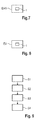
- Figure 7 shows a block diagram of a driver assistance system DAS comprising a device 1 for determining a distance D to a vehicle V according to any of the previous embodiments.
- Figure 8 shows a block diagram of an ego-vehicle EV comprising a device 1 for determining a distance to a neighboring vehicle V according to any of the previous embodiments.
- Figure 9 shows a flowchart of a method for determining a distance D to a vehicle V.
- a camera image CI of the vehicle V is captured.
- an identification tag of the vehicle V is recognized, and in a third step S3, vehicle information about the vehicle V is obtained from a database DB, based on the recognized identification tag of the vehicle V.
- the vehicle information comprises a dimension of the vehicle V.
- a current distance to the vehicle V is determined based on the dimension of the vehicle V comprised in the vehicle information and on a vehicle image dimension of the vehicle V within the captured camera image CI.
- the identification tag is given by a license plate number of the vehicle V.
- the identification tag is preferably recognized on the basis of the camera image CI.
- the identification tag of the vehicle V is obtained from the vehicle V via a remote connection RC2.
- the vehicle information further comprises a feature of the vehicle V other than the dimension of the vehicle V.
- the feature of the vehicle V is recognized, and the feature of the vehicle V comprised in the vehicle information is verified based on the recognized feature of the vehicle V. If the verification of the feature of the vehicle V is positive, a recognized identification tag of the vehicle V is confirmed. In contrast, if the verification of the feature of the vehicle V is negative, the recognized identification tag of the vehicle V is rejected and a new identification tag of the vehicle V is recognized.
- a comparison distance is determined based on a standard license plate size obtained from the database DB and on a license plate image size of the license plate within the captured camera image CI.
- the method can comprise any of the further step described above for the device.
- the terms “comprise”, “comprising”, “include”, “including”, “contain”, “containing”, “have”, “having”, and any variations thereof, are intended to be understood in an inclusive (i.e. non-exclusive) sense, such that the process, method, device, apparatus or system described herein is not limited to those features or parts or elements or steps recited but may include other elements, features, parts or steps not expressly listed or inherent to such process, method, article, or apparatus.
- the terms “a” and “an” used herein are intended to be understood as meaning one or more unless explicitly stated otherwise.
- the terms “first”, “second”, “third”, etc. are used merely as labels, and are not intended to impose numerical requirements on or to establish a certain ranking of importance of their objects.
Landscapes
- Engineering & Computer Science (AREA)
- Physics & Mathematics (AREA)
- General Physics & Mathematics (AREA)
- Theoretical Computer Science (AREA)
- Multimedia (AREA)
- Computer Vision & Pattern Recognition (AREA)
- Traffic Control Systems (AREA)
- Image Analysis (AREA)
Abstract
Description
- The invention relates to a device and a method for determining a distance to a vehicle. In particular, the invention relates to a device for determining a distance to a neighboring vehicle for use in an ego-vehicle. The invention further relates to a driver assistance system and a vehicle.
- Modern driver assistance systems can assist the driver by performing certain driving functions or can autonomously drive the vehicle without the need of any further interventions by the driver. In order to perform driving functions, a detailed and precise knowledge of the surrounding of the vehicle is required. For this purpose, modern vehicles comprise a plurality of sensors which can measure the distance from the vehicle to other objects within its surrounding.
- Radar sensors provide a good accuracy for measuring the distance of objects up to several hundred meters. However, the angular resolution of radar sensors is usually not very high. In order to obtain a good angular localization, multiple antennas are needed which raises the costs of such a sensor system.
- As an alternative, stereo cameras allow a calculation of the distance based on a triangulation method. Such cameras are usually rather expensive and require high computing power.
- Laser sensors or Lidar sensors, such as the device known from document
US 5266955 A , measure the time of flight of the emitted laser light in order to determine the distance of objects. The accuracy of these sensors is usually rather restricted. - Correspondingly, there is a need to measure distances at good precision with reasonable demands on costs and computing power. In particular, there is a need for a setup to measure distances which can be realized by simple hardware components.
- The present invention provides a device for determining a distance to a vehicle with the features as recited in
claim 1. The invention further provides a driver assistance system with the features as recited inclaim 8, a vehicle with the features as recited in claim 9, and a method for determining a distance to a vehicle with the features as recited in claim 10. - According to a first aspect, a device for determining a distance to a vehicle is provided, which comprises a sensor unit that is adapted to capture a camera image of the vehicle. The device further comprises a recognizing unit which is adapted to recognize an identification tag of the vehicle, and an information-obtaining unit which is adapted to obtain vehicle information about the vehicle from a database, based on the recognized identification tag of the vehicle. The vehicle information comprises a dimension of the vehicle. The device further comprises a distance-determining unit which is adapted to determine a current distance to the vehicle, based on the dimension of the vehicle comprised in the vehicle information and on a vehicle image dimension of the vehicle within the captured camera image.
- Preferably, the identification tag of the vehicle can be a physical feature of the vehicle or information about the vehicle which allows an unambiguous identification of the vehicle. The database preferably comprises vehicle information of a large set of vehicles, for instance all vehicles registered in a certain city, region, country, continent, or of all vehicles registered world-wide. The dimension of the vehicle can include information about the size of the vehicle, for instance a width and/or a length and/or a height of the vehicle, but can also comprise a distance between certain well-defined elements or features of the vehicle, such as a distance between the stop lamps of the vehicle or a width and/or length of the license plate of the vehicle. The vehicle image dimension preferably refers to a size, preferably measured in pixels, of a region of the camera image of the vehicle which corresponds to the respective physical dimension of the vehicle.
- According to a second aspect of the invention, a driver assistance system comprising a device for determining a distance to a vehicle is provided.
- According to a third aspect, the invention provides a vehicle comprising a device for determining a distance to a neighboring vehicle.
- According to a fourth aspect of the invention, a method for determining a distance to a vehicle is provided. A camera image of the vehicle is captured and an identification tag of the vehicle is recognized. Vehicle information about the vehicle is obtained from a database, based on the recognized identification tag of the vehicle. The vehicle information comprises a dimension of the vehicle. Further, a current distance to the vehicle is determined, based on the dimension of the vehicle comprised in the vehicle information and on a vehicle image dimension of the vehicle within the captured camera image.
- The invention provides a reliable method for determining a distance to a vehicle with high precision. No additional hardware components are needed apart from those usually already present in modern vehicles. Therefore, the device and the method can be implemented in an easy and economical way.
- According to an embodiment, the device comprises a memory for storing the database. In this case, the device can be autonomously used without the need of a remote connection to the vehicle.
- According to another preferred embodiment, the device comprises a remote interface which is adapted to receive and to store at least a subset of the database from a server via a remote connection. In this case, it is possible to update and modify the database in a central way at the server. The device has always access to the most recent and up-to-date vehicle information.
- According to another embodiment of the invention, the remote interface is adapted to send GPS coordinates of the device to the server via the remote connection. The subset of the database depends on the GPS coordinates of the device. For instance, a traffic monitoring system can recognize the vehicles which are present in certain regions, sections of a road or areas. The traffic monitoring system may recognize the vehicles that pass a certain section of a road and may further store the moment in time when each vehicle passes this section. Preferably, the traffic monitoring system sends to the receiving device the identification tags of the vehicles that passed the section of the road and the corresponding moment in time when each vehicle passed the area. The recognizing unit is adapted to identify the vehicles based on the vehicle identification tags and the time of passing the area. In this way, the recognizing unit is able to increase the accuracy and to reduce the time needed for identification of the vehicles in the vicinity. Depending on the GPS coordinates, the device may only receive and store the vehicle information of vehicles which have been identified within the region around the device. Therefore, not the entire database has to be stored and less memory space is needed.
- According to another embodiment of the device, the recognizing unit is adapted to recognize the identification tag of the vehicle on the basis of the camera image. Therefore, there is no need for any additional sensors.
- According to a further embodiment of the device, the recognizing unit comprises a vehicle interface which is adapted to receive the identification tag from the vehicle via a remote connection. The vehicle interface can be part of a car-to-car communication. Since the vehicle identifies itself, there is no danger of misrecognition.
- According to another embodiment of the invention, the vehicle information obtained by the information-obtaining unit further comprises a feature of the vehicle other than the dimension of the vehicle. The sensor unit is adapted to recognize the feature of the vehicle, and the device further comprises a check unit, which is adapted to verify the feature of the vehicle comprised in the vehicle information based on the feature of the vehicle recognized by the sensor unit. If the verification of the feature of the vehicle is positive, the check unit is further adapted to confirm the recognized identification tag of the vehicle. If the verification of the feature of the vehicle is negative, the check unit is further adapted to reject the recognized identification tag of the vehicle. In this case, the check unit controls the recognizing unit to recognize a new identification tag of the vehicle. This embodiment allows double-checking that the identification tag is correct, i.e., really corresponds to the vehicle. The feature of the vehicle can comprise for instance at least one of a color of the vehicle, a model of the vehicle, a brand of the vehicle, a presence of particular elements such as a third stop lamp, or the color or size of the license plate of the vehicle.
- According to another embodiment of the method, the identification tag is given by a license plate number of the vehicle. This allows an easy and unique identification of the vehicle.
- According to another embodiment of the method, the identification tag is recognized on the basis of the camera image.
- According to a further embodiment of the method, the identification tag of the vehicle is obtained from the vehicle via a remote connection.
- According to a further embodiment of the method, the vehicle information further comprises a feature of the vehicle other than the dimension of the vehicle. The feature of the vehicle is recognized and the feature of the vehicle comprised in the vehicle information is verified based on the recognized feature of the vehicle. If the verification of the feature of the vehicle is positive, the recognized identification tag of the vehicle is confirmed. If the verification of the feature of the vehicle is negative, the recognized identification tag of the vehicle is rejected and a new identification tag of the vehicle is recognized.
- According to another preferred embodiment of the method, a comparison distance is determined based on a standard license plate size obtained from the database and on a license plate image size of the license plate within the captured camera image. The determined current distance is confirmed based on the comparison distance. The standard license plate size can be determined as the standard size of license plates within the country where the device is currently located, which can be determined based on GPS coordinates of the device. The determined current distance can be confirmed if a difference between the determined current distance and the comparison distance is smaller than a predetermined threshold value. Otherwise, the determined current distance can be rejected.
- For a more complete understanding of the invention and the advantages thereof, exemplary embodiments of the invention are explained in more detail in the following description with reference to the accompanying drawing figures, in which like reference characters designate like parts and in which:
- Fig. 1
- shows a block diagram of a device for determining a distance to a vehicle according to a first embodiment of the invention;
- Fig. 2
- shows a block diagram of a device for determining a distance to a vehicle according to a second embodiment of the invention;
- Fig. 3
- shows a block diagram of a device for determining a distance to a vehicle according to a third embodiment of the invention;
- Fig. 4
- shows a schematic top view on an illustrative scenario for explaining the determination of the distance, and a corresponding camera image;
- Fig. 5
- shows a top view on an illustrative scenario for explaining the determination of the distance to a neighboring vehicle, which is driving in front of the ego-vehicle;
- Fig. 6
- shows a schematic top view on an illustrative scenario for explaining the determination of the distance to a neighboring vehicle, which is driving in parallel to the ego-vehicle;
- Fig. 7
- shows a block diagram of a driver assistance system according to an embodiment of the invention;
- Fig. 8
- shows a block diagram of a vehicle according to an embodiment of the invention; and
- Fig. 9
- shows a flowchart of a method for determining a distance to a vehicle according to an embodiment of the invention.
- The accompanying drawings are included to provide a further understanding of the present invention and are incorporated in and constitute a part of this specification. The drawings illustrate particular embodiments of the invention and together with the description serve to explain the principles of the invention. Other embodiments of the invention and many of the attendant advantages of the invention will be readily appreciated as they become better understood with reference to the following detailed description.
- It will be appreciated that common and well understood elements that may be useful or necessary in a commercially feasible embodiment are not necessarily depicted in order to facilitate a more abstracted view of the embodiments. The elements of the drawings are not necessarily illustrated to scale relative to each other. It will further be appreciated that certain actions and/or steps in an embodiment of a method may be described or depicted in a particular order of occurrences while those skilled in the art will understand that such specificity with respect to sequence is not actually required. It will also be understood that the terms and expressions used in the present specification have the ordinary meaning as is accorded to such terms and expressions with respect to their corresponding respective areas of inquiry and study, except where specific meanings have otherwise been set forth herein.
-
Figure 1 shows a block diagram of adevice 1a for determining a distance to a vehicle according to a first embodiment of the invention. - Preferably, the device is adapted for use within an ego-vehicle for determining a distance to another neighboring vehicle. Further, the device can also be used for traffic control or monitoring systems.
- A vehicle can comprise a motor vehicle such as a car, a truck, an aircraft, an eBike, a scooter, a motorcycle or a boat.
- The
device 1a comprises asensor unit 2 which is adapted to capture a camera image of the vehicle. Thesensor unit 2 can comprise one or more cameras, preferably a surround view system. - The device further comprises a recognizing
unit 3 which is adapted to recognize an identification tag of the vehicle. According to a preferred embodiment, the identification tag is given by a license plate number of the vehicle. Preferably, the recognizingunit 3 is adapted to recognize the license plate number of the vehicle based on the camera image of the vehicle. - The
device 1a further comprises an information-obtainingunit 4 which is adapted to obtain vehicle information about the vehicle from a database DB. The database DB may be part of thedevice 1a or may be an external database DB. The database DB preferably comprises a list of a large number of vehicles which preferably has the form of a hash table, wherein a key is given by the identification tag of the vehicles. For each identification tag, vehicle information of the corresponding vehicle is stored in the database DB. The information-obtainingunit 4 is adapted to obtain the vehicle information about the vehicle corresponding to the recognized identification tag of the vehicle. - The vehicle information comprises a dimension of the vehicle, which may comprise a width and/or a length and/or a height of the vehicle. The information of the vehicle can also comprise a distance between two elements of the vehicle, such as the two stop lights of the vehicle. The vehicle information can also comprise the size, i.e. the width and a length of the license plate of the vehicle.
- Further, the device comprises a distance-determining
unit 5, which is adapted to determine a current distance to the vehicle, based on the dimension of the vehicle comprised in the vehicle information and on a vehicle image dimension of the vehicle within the captured camera image. - According to an embodiment, a quotient of a vehicle image dimension of the vehicle and the dimension of the vehicle comprised in the vehicle information is computed. For instance, a width of a vehicle image of the vehicle within the captured camera image is divided by an actual physical width of the vehicle comprised in the vehicle information. The distance-determining
unit 5 comprises a lookup table, which assigns a distance to the vehicle for a large number of quotients. The distance-determiningunit 5 is then adapted to determine the distance to the vehicle using the lookup table and the quotient. -
Figure 2 shows a block diagram of adevice 1b for determining a distance to a vehicle according to a second embodiment of the invention. Thedevice 1b additionally comprises amemory 6 for storing the database DB. Thus, the database DB is locally stored on thememory 6 of thedevice 1b. -
Fig. 3 shows a block diagram of adevice 1c for determining a distance to a vehicle according to a third embodiment of the invention. Thedevice 1c comprises aremote interface 7, which is adapted to receive and store at least a subset of the database DB from a server S via a first remote connection RC1. Thedevice 1c and the server S can be part of a system. - The
remote interface 7 can be adapted to send GPS coordinates of thedevice 1c to the server S via the first remote connection RC1. The database DB on the server S is classified and divided according to a number of spatial regions. For instance, a traffic monitoring system can identify the vehicles at certain locations of the road, for instance by their license plate, and can thus determine which vehicles are located within a given spatial region during a given time interval. Based on the GPS coordinates of the device, only the subset of the database corresponding to the spatial region around the device is received and stored via theremote interface 7. - According to another embodiment, the
remote interface 7 is adapted to transmit the recognized identification tag to the server S, such that the database DB on the server S can be updated by adding the current position of the vehicle corresponding to the recognized identification tag. The current position can be part of the vehicle information of the vehicle. - The recognizing
unit 3 of thedevice 1c further comprises avehicle interface 30, which is adapted to receive the identification tag, preferably the license plate number, from the vehicle via a second remote connection RC2. - The vehicle information obtained by the information-obtaining
unit 4 further comprises at least one additional feature of the vehicle other than the dimension of the vehicle. In particular, the additional feature can comprise a color of the vehicle, a brand of the vehicle or a distance between the stop lights of the vehicle. Thesensor unit 2 is further adapted to measure or recognize the feature of the vehicle. Thesensor unit 2 can comprise a plurality of further sensors for this task, such as radar sensors, lidar sensors, laser sensors, or additional cameras. - The
device 1c further comprises acheck unit 8 which is adapted to verify the feature of the vehicle comprised in the vehicle information based on the feature of the vehicle recognized by thesensor unit 2. For instance, the vehicle information corresponding to a recognized identification tag includes that the vehicle is of green color. With a camera of thesensor unit 2, the color of the vehicle can be recognized. Thecheck unit 8 verifies whether the recognized color of the vehicle is green, i.e., is identical to the color comprised in the vehicle information. If this is the case, the verification is positive, i.e., the feature of the vehicle comprised in the vehicle information is identical to the feature of the vehicle recognized by thesensor unit 2. If the verification of the feature of the vehicle is positive, thecheck unit 8 is further adapted to confirm the recognized identification tag of the vehicle. Acheck unit 8 transmits a signal to the information-obtainingunit 4 to proceed further with obtaining the vehicle information. - If the verification of the feature of the vehicle is negative, i.e., the feature of the vehicle comprised in the vehicle information is not identical to the feature of the vehicle recognized by the
sensor unit 2, thecheck unit 8 is further adapted to reject the recognized identification tag of the vehicle. In this case, thecheck unit 8 is adapted to control the recognizingunit 3 to recognize a new identification tag of the vehicle. This process is reiterated until the verification of the feature of the vehicle is positive. Only in this case, the information-obtainingunit 4 obtains the vehicle information about the vehicle from the database DB. - The upper part of
Figure 4 shows a schematic top view on a scene comprising an ego-vehicle EV with a device for determining a distance to a vehicle V according to any of the previous embodiments, and a neighboring vehicle V (in the following simply denoted as "vehicle V"). The lower part ofFigure 4 illustrates a schematic camera image CI of the vehicle V captured by thesensor unit 2 of the device of the ego-vehicle EV. The camera image CI comprises a vehicle image, i.e., an image of the vehicle V. - The
sensor unit 2 comprises a vehicle camera with an opening angle φ (angle of view). The vehicle V is located at a distance D from the ego-vehicle EV. The area captured by thesensor unit 2 at the distance D has a horizontal extent d. In the camera image CI, the horizontal extent d corresponds to a width Nx of the camera image CI, measured in pixels. - By observing a license plate LP of the vehicle V, the recognizing
unit 3 is adapted to recognize a license plate number of the vehicle V. Based on the license plate number, the information-obtainingunit 4 obtains vehicle information about the vehicle V from the database, which comprises a width w of the vehicle V. - The distance-determining
unit 5 is adapted to determine the vehicle image dimension of the vehicle V from the camera image (CI), which comprises a width Nw of the vehicle image, which is measured in numbers of pixels. The distance-determiningunit 5 is adapted to determine a current distance D of the vehicle V, based on the following formula:
- This formula follows from the following geometric relation:

- As an example, the
sensor unit 2 comprises a front view camera with an opening angle φ = 45° and a horizontal resolution or width Nx of the camera image given by Nx = 1920 pixels. The width w of the vehicle V comprised in the vehicle information obtained from the database DB is given by w = 1.8 m. The distance-determiningunit 5 determines the width Nw of the vehicle image to be 200 pixels. The distance-determiningunit 5 then determines the distance D of the vehicle V using the above formula as follows:
- According to another embodiment, the distance-determining
unit 5 has stored information about an optical distortion of thesensor unit 2. The distortion can be taken into account by a gradient formula grad(α), wherein α describes an angle of pixels from a center of the camera image CI, corresponding to an optical axis of thesensor unit 2. The angle α is increasing for pixels on the edge of the image sensor. The maximum value for the angle α is given by the opening angle φ of thesensor unit 2. In this case, the distance-determiningunit 5 is adapted to determine the current distance D of the vehicle V by the following formula:
- The distance-determining
unit 5 can also determine the current distance D of the vehicle V based on a distance Ns between stop lights within the vehicle image and an actual physical distance between the stop lights comprised in the vehicle information about the vehicle V. The distance-determiningunit 5 can also determine the current distance D of the vehicle V based on a height Nh of the vehicle image, a height Ny of the camera image CI measured in pixels, and a physical height of the vehicle V comprised in the vehicle information about the vehicle V. The corresponding formulas are similar to the formulas above. -
Figure 5 shows schematic top views on traffic scenario for illustrating the determination of the distance D. The upper part ofFigure 5 shows a vehicle V at a distance D in front of an ego-vehicle EV at a first time t1. The lower part ofFigure 5 shows the vehicle V at a distance D to the ego-vehicle EV at a second time t2. Preferably, the recognizingunit 3 recognizes the identification tag of the vehicle V only at the first time t1, wherein the distance-determiningunit 5 is adapted to determine the current distance D of the vehicle V for an arbitrary number of different time points, in particular both at the first time t1 and at the second time t2. In particular, after an initial recognition of the vehicle V, the distance-determiningunit 5 can continuously determine the current distance D to the vehicle V. - The lower part of
Figure 6 shows a schematic top view on an illustrative traffic scenario showing an ego-vehicle EV comprising a device for determining a distance to a vehicle V according to any of the above embodiments. A vehicle V is driving on a traffic lane parallel to the ego-vehicle EV. The location of the vehicle V is illustrated at a first time t1 and at a second time t2. At the first time t1, a license plate LP of the vehicle V is visible to thesensor unit 2 of the ego-vehicle EV and the recognizingunit 3 identifies a license plate number from the license plate LP of the vehicle V. The information-obtainingunit 4 obtains vehicle information from the database DB based on the identified license plate number. At the second time t2, the distance to the vehicle V from thesensor unit 2 is determined by the distance-determiningunit 5. The top part ofFigure 6 shows a corresponding camera image CI of the vehicle V at the second time t2 comprising a vehicle image of the vehicle V. The distance-determiningunit 5 can determine the current distance D of the vehicle V based on the relation of a length Nl of the vehicle image, measured in pixels, and a width Nx of the camera image CI. This ratio is compared to anactual length 1 of the vehicle V comprised in the vehicle information about the vehicle V. The distance-determiningunit 5 determines the distance D based the formulas as above, using an opening angle φ of thesensor unit 2. - According to another embodiment, the distance-determining
unit 5 can determine the distance D of the vehicle V based on a height Nh of the vehicle image, a height Ny of the camera image CI, and a physical height of the vehicle V comprised in the vehicle information about the vehicle V. The dimension of the vehicle can also be a physical width of a vehicle door of the vehicle V which is compared to a vehicle image width Nz of the vehicle door. - According to a further embodiment, the distance-determining
unit 5 determines a comparison distance to the vehicle based on a standard license plate size obtained from the database DB and on a license plate image size of the license plate within the captured camera image CI. If a difference between the comparison distance to the vehicle and the determined current distance D to the vehicle V is below a predetermined value, the determined current distance D to the vehicle V is confirmed. Otherwise, the current distance D to the vehicle V is rejected and a new determination is performed. -
Figure 7 shows a block diagram of a driver assistance system DAS comprising adevice 1 for determining a distance D to a vehicle V according to any of the previous embodiments. -
Figure 8 shows a block diagram of an ego-vehicle EV comprising adevice 1 for determining a distance to a neighboring vehicle V according to any of the previous embodiments. -
Figure 9 shows a flowchart of a method for determining a distance D to a vehicle V. In a first method step S1, a camera image CI of the vehicle V is captured. In a second step S2, an identification tag of the vehicle V is recognized, and in a third step S3, vehicle information about the vehicle V is obtained from a database DB, based on the recognized identification tag of the vehicle V. The vehicle information comprises a dimension of the vehicle V. Further, in a step S4, a current distance to the vehicle V is determined based on the dimension of the vehicle V comprised in the vehicle information and on a vehicle image dimension of the vehicle V within the captured camera image CI. - Preferably, the identification tag is given by a license plate number of the vehicle V.
- The identification tag is preferably recognized on the basis of the camera image CI.
- According to an embodiment, the identification tag of the vehicle V is obtained from the vehicle V via a remote connection RC2.
- According to a preferred embodiment, the vehicle information further comprises a feature of the vehicle V other than the dimension of the vehicle V. The feature of the vehicle V is recognized, and the feature of the vehicle V comprised in the vehicle information is verified based on the recognized feature of the vehicle V. If the verification of the feature of the vehicle V is positive, a recognized identification tag of the vehicle V is confirmed. In contrast, if the verification of the feature of the vehicle V is negative, the recognized identification tag of the vehicle V is rejected and a new identification tag of the vehicle V is recognized.
- According to an embodiment, a comparison distance is determined based on a standard license plate size obtained from the database DB and on a license plate image size of the license plate within the captured camera image CI.
- The method can comprise any of the further step described above for the device.
- Although specific embodiments of the invention have been illustrated and described herein, it will be appreciated by those of ordinary skill in the art that a variety of alternate and/or equivalent implementations exist. It should be appreciated that the exemplary embodiment or exemplary embodiments are only examples, and are not intended to limit the scope, applicability, or configuration in any way. Rather, the foregoing summary and detailed description will provide those skilled in the art with a convenient road map for implementing at least one exemplary embodiment, it being understood that various changes may be made in the function and arrangement of elements described in an exemplary embodiment without departing from the scope as set forth in the appended claims and their legal equivalents. Generally, this application is intended to cover any adaptations or variations of the specific embodiments discussed herein.
- In this document, the terms "comprise", "comprising", "include", "including", "contain", "containing", "have", "having", and any variations thereof, are intended to be understood in an inclusive (i.e. non-exclusive) sense, such that the process, method, device, apparatus or system described herein is not limited to those features or parts or elements or steps recited but may include other elements, features, parts or steps not expressly listed or inherent to such process, method, article, or apparatus. Furthermore, the terms "a" and "an" used herein are intended to be understood as meaning one or more unless explicitly stated otherwise. Moreover, the terms "first", "second", "third", etc. are used merely as labels, and are not intended to impose numerical requirements on or to establish a certain ranking of importance of their objects.
-
- 1a
- device for determining a distance to a vehicle
- 1b
- device for determining a distance to a vehicle
- 1c
- device for determining a distance to a vehicle
- 2
- sensor unit
- 3
- recognizing unit
- 4
- information-obtaining unit
- 5
- distance-determining unit
- 6
- memory
- 7
- remote interface
- 8
- check unit
- CI
- camera image
- d
- horizontal extent
- D
- distance to the vehicle
- DB
- database
- EV
- ego-vehicle
- Nw
- width of the vehicle image
- Nh
- height of the vehicle image
- Ns
- distance between stop lights within the vehicle image
- Nx
- width of the camera image
- Ny
- height of the camera image
- RC1
- first remote connection
- RC2
- second remote connection
- S
- server
- t1
- first time
- t2
- second time
- V
- vehicle
- w
- width of the vehicle
- φ
- opening angle
Claims (15)
- A device (1; 1a; 1b; 1c) for determining a distance (D) to a vehicle (V), comprising:a sensor unit (2), adapted to capture a camera image (CI) of the vehicle (V);a recognizing unit (3), adapted to recognizing an identification tag of the vehicle (V);an information-obtaining unit (4), adapted to obtain vehicle information about the vehicle (V) from a database (DB), based on the recognized identification tag of the vehicle (V), wherein the vehicle information comprises a dimension of the vehicle (V); anda distance-determining unit (5), adapted to determine a current distance (D) to the vehicle (V), based on the dimension of the vehicle (V) comprised in the vehicle information and on a vehicle image dimension of the vehicle (V) within the captured camera image (CI).
- The device (1; 1b) according to claim 1, comprising a memory (6) for storing the database (DB).
- The device (1; 1c) according to claim 1 or 2, comprising a remote interface (7), adapted to receive and store at least a subset of the database (DB) from a server (S) via a remote connection (RC1).
- The device (1; 1c) according to claim 3, wherein the remote interface (7) is adapted to send GPS coordinates of the device (1; 1a; 1b; 1c) to the server (S) via the remote connection (RC1), and wherein the subset of the database depends on the GPS coordinates of the device (1; 1a; 1b; 1c).
- The device (1; 1a; 1b; 1c) according to any of the preceding claims, wherein the recognizing unit (3) is adapted to recognize the identification tag on the basis of the camera image (CI).
- The device (1; 1c) according to any of the preceding claims, wherein the recognizing unit (3) comprises a vehicle interface (30), adapted to receive the identification tag from the vehicle (V) via a remote connection (RC2).
- The device (1; 1c) according to any of the preceding claims, wherein:the vehicle information obtained by the information-obtaining unit (4) further comprises a feature of the vehicle (V) other than the dimension of the vehicle (V);the sensor unit (2) is adapted to recognize the feature of the vehicle (V);the device (1; 1c) further comprises a check unit (8), adapted to verify the feature of the vehicle (V) comprised in the vehicle information based on the feature of the vehicle (V) recognized by the sensor unit (2);if the verification of the feature of the vehicle (V) is positive, the check unit (8) is further adapted to confirm the recognized identification tag of the vehicle (V); andif the verification of the feature of the vehicle (V) is negative, the check unit (8) is further adapted to reject the recognized identification tag of the vehicle (V) and to control the recognizing unit (3) to recognize a new identification tag of the vehicle (V).
- A driver assistance system (DAS) comprising a device (1; 1a; 1b; 1c) for determining a distance (D) to a vehicle (V) according to any of claims 1 to 7.
- A vehicle (EV) comprising a device (1; 1a; 1b; 1c) for determining a distance (D) to a neighboring vehicle (V) according to any of claims 1 to 7.
- A method for determining a distance (D) to a vehicle (V), comprising the steps:capturing (S1) a camera image (CI) of the vehicle (V);recognizing (S2) an identification tag of the vehicle (V);obtaining (S3) vehicle information about the vehicle (V) from a database, based on the recognized identification tag of the vehicle (V), wherein the vehicle information comprises a dimension of the vehicle (V); anddetermining (S4) a current distance (D) to the vehicle (V), based on the dimension of the vehicle (V) comprised in the vehicle information and on a vehicle image dimension of the vehicle (V) within the captured camera image (CI).
- The method according to claim 10, wherein the identification tag is given by a license plate number of the vehicle (V).
- The method according to claim 10 or 11, wherein the identification tag of the vehicle (V) is recognized on the basis of the camera image (CI).
- The method according to any of claims 10 to 12, wherein the identification tag of the vehicle (V) is obtained from the vehicle (V) via a remote connection (RC2).
- The method according to any of claims 10 to 13, wherein the vehicle information further comprises a feature of the vehicle (V) other than the dimension of the vehicle (V), the method further comprising the following steps:recognizing the feature of the vehicle (V); andverifying the feature of the vehicle (V) comprised in the vehicle information based on the recognized feature of the vehicle (V);wherein, if the verification of the feature of the vehicle is positive, the recognized identification tag of the vehicle (V) is confirmed; andwherein, if the verification of the feature of the vehicle is negative, the recognized identification tag of the vehicle (V) is rejected and a new identification tag of the vehicle (V) is recognized.
- The method according to any of claims 10 to 14, wherein a comparison distance is determined based on a standard license plate size obtained from the database (DB) and on a license plate image size of the license plate (LP) within the captured camera image (CI), and wherein the determined current distance (D) is confirmed based on the comparison distance.
Priority Applications (1)
| Application Number | Priority Date | Filing Date | Title |
|---|---|---|---|
| EP16465520.1A EP3273408B1 (en) | 2016-07-19 | 2016-07-19 | Device and method for determining a distance to a vehicle |
Applications Claiming Priority (1)
| Application Number | Priority Date | Filing Date | Title |
|---|---|---|---|
| EP16465520.1A EP3273408B1 (en) | 2016-07-19 | 2016-07-19 | Device and method for determining a distance to a vehicle |
Publications (2)
| Publication Number | Publication Date |
|---|---|
| EP3273408A1 true EP3273408A1 (en) | 2018-01-24 |
| EP3273408B1 EP3273408B1 (en) | 2020-09-09 |
Family
ID=56787403
Family Applications (1)
| Application Number | Title | Priority Date | Filing Date |
|---|---|---|---|
| EP16465520.1A Active EP3273408B1 (en) | 2016-07-19 | 2016-07-19 | Device and method for determining a distance to a vehicle |
Country Status (1)
| Country | Link |
|---|---|
| EP (1) | EP3273408B1 (en) |
Cited By (2)
| Publication number | Priority date | Publication date | Assignee | Title |
|---|---|---|---|---|
| WO2020214294A1 (en) * | 2019-04-15 | 2020-10-22 | Qualcomm Incorporated | Proximate vehicle localization and identification |
| WO2023097125A1 (en) * | 2021-11-24 | 2023-06-01 | Harman Connected Services, Inc. | Systems and methods for automatic camera calibration |
Citations (6)
| Publication number | Priority date | Publication date | Assignee | Title |
|---|---|---|---|---|
| US5266955A (en) | 1991-07-08 | 1993-11-30 | Kansei Corporation | Laser-radar type distance measuring equipment |
| JPH1096626A (en) * | 1996-09-20 | 1998-04-14 | Oki Electric Ind Co Ltd | Detector for distance between vehicles |
| US5867256A (en) * | 1997-07-16 | 1999-02-02 | Raytheon Ti Systems, Inc. | Passive range estimation using image size measurements |
| US20090240432A1 (en) * | 2008-03-18 | 2009-09-24 | Denso Corporation | Vehicle-installation obstacle detection apparatus |
| US20160150070A1 (en) * | 2013-07-18 | 2016-05-26 | Secure4Drive Communication Ltd. | Method and device for assisting in safe driving of a vehicle |
| EP3035315A1 (en) * | 2014-12-15 | 2016-06-22 | Volvo Car Corporation | Information retrieval arrangement |
-
2016
- 2016-07-19 EP EP16465520.1A patent/EP3273408B1/en active Active
Patent Citations (6)
| Publication number | Priority date | Publication date | Assignee | Title |
|---|---|---|---|---|
| US5266955A (en) | 1991-07-08 | 1993-11-30 | Kansei Corporation | Laser-radar type distance measuring equipment |
| JPH1096626A (en) * | 1996-09-20 | 1998-04-14 | Oki Electric Ind Co Ltd | Detector for distance between vehicles |
| US5867256A (en) * | 1997-07-16 | 1999-02-02 | Raytheon Ti Systems, Inc. | Passive range estimation using image size measurements |
| US20090240432A1 (en) * | 2008-03-18 | 2009-09-24 | Denso Corporation | Vehicle-installation obstacle detection apparatus |
| US20160150070A1 (en) * | 2013-07-18 | 2016-05-26 | Secure4Drive Communication Ltd. | Method and device for assisting in safe driving of a vehicle |
| EP3035315A1 (en) * | 2014-12-15 | 2016-06-22 | Volvo Car Corporation | Information retrieval arrangement |
Cited By (4)
| Publication number | Priority date | Publication date | Assignee | Title |
|---|---|---|---|---|
| WO2020214294A1 (en) * | 2019-04-15 | 2020-10-22 | Qualcomm Incorporated | Proximate vehicle localization and identification |
| US11222219B2 (en) | 2019-04-15 | 2022-01-11 | Qualcomm Incorporated | Proximate vehicle localization and identification |
| WO2023097125A1 (en) * | 2021-11-24 | 2023-06-01 | Harman Connected Services, Inc. | Systems and methods for automatic camera calibration |
| US20250037311A1 (en) * | 2021-11-24 | 2025-01-30 | Harman Connected Services, Inc. | Systems and methods for automatic camera calibration |
Also Published As
| Publication number | Publication date |
|---|---|
| EP3273408B1 (en) | 2020-09-09 |
Similar Documents
| Publication | Publication Date | Title |
|---|---|---|
| CN110146097B (en) | Method and system for generating automatic driving navigation map, vehicle-mounted terminal and server | |
| US11455808B2 (en) | Method for the classification of parking spaces in a surrounding region of a vehicle with a neural network | |
| CN113127583B (en) | Data transmission method and device | |
| CN110942623B (en) | A kind of auxiliary traffic accident processing method and system | |
| US9569962B2 (en) | Method for identifying a vehicle detected by a sensor device | |
| EP3705371A1 (en) | Obstacle detecting device | |
| US10846546B2 (en) | Traffic signal recognition device | |
| CN108475467B (en) | Method for identifying wrongly parked cars | |
| CN110998684B (en) | Image collection system, image collection method, image collection device, and recording medium | |
| KR102159144B1 (en) | Unmanned vehicle crackdown system around a walking signal | |
| CN106370162A (en) | Animal type determination device | |
| JP6302920B2 (en) | Method and means for recognizing marked danger locations and / or construction sites in the area of the roadway | |
| CN110717438A (en) | Traffic signal lamp identification method and device | |
| CN103890784A (en) | Apparatus and method for detecting objects in a stream of sensor data | |
| JP2019067201A (en) | Vehicle search system, vehicle search method, and vehicle and program employed in the same | |
| JP2015535106A5 (en) | ||
| CN112896160B (en) | Traffic sign information acquisition method and related equipment | |
| EP3273408B1 (en) | Device and method for determining a distance to a vehicle | |
| US11935414B1 (en) | Identification of confusing objects for color deficient vision | |
| CN105702027A (en) | Information retrieval arrangement | |
| EP3223188A1 (en) | A vehicle environment mapping system | |
| CN111731304B (en) | Vehicle control device, vehicle control method, and storage medium | |
| CN110745145A (en) | Multi-sensor management system for ADAS | |
| KR20140085848A (en) | Detecting system of traffic signal based on vehicle position, and detecting method using the system | |
| CN105283873B (en) | Method and system for finding one or more persons passing by a vehicle |
Legal Events
| Date | Code | Title | Description |
|---|---|---|---|
| PUAI | Public reference made under article 153(3) epc to a published international application that has entered the european phase |
Free format text: ORIGINAL CODE: 0009012 |
|
| STAA | Information on the status of an ep patent application or granted ep patent |
Free format text: STATUS: THE APPLICATION HAS BEEN PUBLISHED |
|
| AK | Designated contracting states |
Kind code of ref document: A1 Designated state(s): AL AT BE BG CH CY CZ DE DK EE ES FI FR GB GR HR HU IE IS IT LI LT LU LV MC MK MT NL NO PL PT RO RS SE SI SK SM TR |
|
| AX | Request for extension of the european patent |
Extension state: BA ME |
|
| STAA | Information on the status of an ep patent application or granted ep patent |
Free format text: STATUS: REQUEST FOR EXAMINATION WAS MADE |
|
| 17P | Request for examination filed |
Effective date: 20180724 |
|
| RBV | Designated contracting states (corrected) |
Designated state(s): AL AT BE BG CH CY CZ DE DK EE ES FI FR GB GR HR HU IE IS IT LI LT LU LV MC MK MT NL NO PL PT RO RS SE SI SK SM TR |
|
| STAA | Information on the status of an ep patent application or granted ep patent |
Free format text: STATUS: EXAMINATION IS IN PROGRESS |
|
| 17Q | First examination report despatched |
Effective date: 20190924 |
|
| REG | Reference to a national code |
Ref country code: DE Ref legal event code: R079 Ref document number: 602016043615 Country of ref document: DE Free format text: PREVIOUS MAIN CLASS: G06T0007000000 Ipc: G06T0007500000 |
|
| GRAP | Despatch of communication of intention to grant a patent |
Free format text: ORIGINAL CODE: EPIDOSNIGR1 |
|
| STAA | Information on the status of an ep patent application or granted ep patent |
Free format text: STATUS: GRANT OF PATENT IS INTENDED |
|
| INTG | Intention to grant announced |
Effective date: 20200421 |
|
| RIC1 | Information provided on ipc code assigned before grant |
Ipc: G06T 7/50 20170101AFI20200403BHEP |
|
| GRAS | Grant fee paid |
Free format text: ORIGINAL CODE: EPIDOSNIGR3 |
|
| GRAA | (expected) grant |
Free format text: ORIGINAL CODE: 0009210 |
|
| STAA | Information on the status of an ep patent application or granted ep patent |
Free format text: STATUS: THE PATENT HAS BEEN GRANTED |
|
| RAP1 | Party data changed (applicant data changed or rights of an application transferred) |
Owner name: CONTINENTAL AUTOMOTIVE GMBH |
|
| AK | Designated contracting states |
Kind code of ref document: B1 Designated state(s): AL AT BE BG CH CY CZ DE DK EE ES FI FR GB GR HR HU IE IS IT LI LT LU LV MC MK MT NL NO PL PT RO RS SE SI SK SM TR |
|
| REG | Reference to a national code |
Ref country code: GB Ref legal event code: FG4D |
|
| REG | Reference to a national code |
Ref country code: AT Ref legal event code: REF Ref document number: 1312527 Country of ref document: AT Kind code of ref document: T Effective date: 20200915 Ref country code: CH Ref legal event code: EP |
|
| REG | Reference to a national code |
Ref country code: DE Ref legal event code: R096 Ref document number: 602016043615 Country of ref document: DE |
|
| REG | Reference to a national code |
Ref country code: IE Ref legal event code: FG4D |
|
| REG | Reference to a national code |
Ref country code: SE Ref legal event code: TRGR |
|
| REG | Reference to a national code |
Ref country code: LT Ref legal event code: MG4D |
|
| PG25 | Lapsed in a contracting state [announced via postgrant information from national office to epo] |
Ref country code: LT Free format text: LAPSE BECAUSE OF FAILURE TO SUBMIT A TRANSLATION OF THE DESCRIPTION OR TO PAY THE FEE WITHIN THE PRESCRIBED TIME-LIMIT Effective date: 20200909 Ref country code: HR Free format text: LAPSE BECAUSE OF FAILURE TO SUBMIT A TRANSLATION OF THE DESCRIPTION OR TO PAY THE FEE WITHIN THE PRESCRIBED TIME-LIMIT Effective date: 20200909 Ref country code: NO Free format text: LAPSE BECAUSE OF FAILURE TO SUBMIT A TRANSLATION OF THE DESCRIPTION OR TO PAY THE FEE WITHIN THE PRESCRIBED TIME-LIMIT Effective date: 20201209 Ref country code: FI Free format text: LAPSE BECAUSE OF FAILURE TO SUBMIT A TRANSLATION OF THE DESCRIPTION OR TO PAY THE FEE WITHIN THE PRESCRIBED TIME-LIMIT Effective date: 20200909 Ref country code: GR Free format text: LAPSE BECAUSE OF FAILURE TO SUBMIT A TRANSLATION OF THE DESCRIPTION OR TO PAY THE FEE WITHIN THE PRESCRIBED TIME-LIMIT Effective date: 20201210 Ref country code: BG Free format text: LAPSE BECAUSE OF FAILURE TO SUBMIT A TRANSLATION OF THE DESCRIPTION OR TO PAY THE FEE WITHIN THE PRESCRIBED TIME-LIMIT Effective date: 20201209 |
|
| REG | Reference to a national code |
Ref country code: AT Ref legal event code: MK05 Ref document number: 1312527 Country of ref document: AT Kind code of ref document: T Effective date: 20200909 |
|
| REG | Reference to a national code |
Ref country code: NL Ref legal event code: MP Effective date: 20200909 |
|
| PG25 | Lapsed in a contracting state [announced via postgrant information from national office to epo] |
Ref country code: LV Free format text: LAPSE BECAUSE OF FAILURE TO SUBMIT A TRANSLATION OF THE DESCRIPTION OR TO PAY THE FEE WITHIN THE PRESCRIBED TIME-LIMIT Effective date: 20200909 Ref country code: PL Free format text: LAPSE BECAUSE OF FAILURE TO SUBMIT A TRANSLATION OF THE DESCRIPTION OR TO PAY THE FEE WITHIN THE PRESCRIBED TIME-LIMIT Effective date: 20200909 Ref country code: RS Free format text: LAPSE BECAUSE OF FAILURE TO SUBMIT A TRANSLATION OF THE DESCRIPTION OR TO PAY THE FEE WITHIN THE PRESCRIBED TIME-LIMIT Effective date: 20200909 |
|
| PG25 | Lapsed in a contracting state [announced via postgrant information from national office to epo] |
Ref country code: EE Free format text: LAPSE BECAUSE OF FAILURE TO SUBMIT A TRANSLATION OF THE DESCRIPTION OR TO PAY THE FEE WITHIN THE PRESCRIBED TIME-LIMIT Effective date: 20200909 Ref country code: PT Free format text: LAPSE BECAUSE OF FAILURE TO SUBMIT A TRANSLATION OF THE DESCRIPTION OR TO PAY THE FEE WITHIN THE PRESCRIBED TIME-LIMIT Effective date: 20210111 Ref country code: RO Free format text: LAPSE BECAUSE OF FAILURE TO SUBMIT A TRANSLATION OF THE DESCRIPTION OR TO PAY THE FEE WITHIN THE PRESCRIBED TIME-LIMIT Effective date: 20200909 Ref country code: SM Free format text: LAPSE BECAUSE OF FAILURE TO SUBMIT A TRANSLATION OF THE DESCRIPTION OR TO PAY THE FEE WITHIN THE PRESCRIBED TIME-LIMIT Effective date: 20200909 Ref country code: CZ Free format text: LAPSE BECAUSE OF FAILURE TO SUBMIT A TRANSLATION OF THE DESCRIPTION OR TO PAY THE FEE WITHIN THE PRESCRIBED TIME-LIMIT Effective date: 20200909 |
|
| PG25 | Lapsed in a contracting state [announced via postgrant information from national office to epo] |
Ref country code: ES Free format text: LAPSE BECAUSE OF FAILURE TO SUBMIT A TRANSLATION OF THE DESCRIPTION OR TO PAY THE FEE WITHIN THE PRESCRIBED TIME-LIMIT Effective date: 20200909 Ref country code: AT Free format text: LAPSE BECAUSE OF FAILURE TO SUBMIT A TRANSLATION OF THE DESCRIPTION OR TO PAY THE FEE WITHIN THE PRESCRIBED TIME-LIMIT Effective date: 20200909 Ref country code: AL Free format text: LAPSE BECAUSE OF FAILURE TO SUBMIT A TRANSLATION OF THE DESCRIPTION OR TO PAY THE FEE WITHIN THE PRESCRIBED TIME-LIMIT Effective date: 20200909 Ref country code: IS Free format text: LAPSE BECAUSE OF FAILURE TO SUBMIT A TRANSLATION OF THE DESCRIPTION OR TO PAY THE FEE WITHIN THE PRESCRIBED TIME-LIMIT Effective date: 20210109 |
|
| REG | Reference to a national code |
Ref country code: DE Ref legal event code: R097 Ref document number: 602016043615 Country of ref document: DE |
|
| PG25 | Lapsed in a contracting state [announced via postgrant information from national office to epo] |
Ref country code: SK Free format text: LAPSE BECAUSE OF FAILURE TO SUBMIT A TRANSLATION OF THE DESCRIPTION OR TO PAY THE FEE WITHIN THE PRESCRIBED TIME-LIMIT Effective date: 20200909 |
|
| PLBE | No opposition filed within time limit |
Free format text: ORIGINAL CODE: 0009261 |
|
| STAA | Information on the status of an ep patent application or granted ep patent |
Free format text: STATUS: NO OPPOSITION FILED WITHIN TIME LIMIT |
|
| 26N | No opposition filed |
Effective date: 20210610 |
|
| PG25 | Lapsed in a contracting state [announced via postgrant information from national office to epo] |
Ref country code: SI Free format text: LAPSE BECAUSE OF FAILURE TO SUBMIT A TRANSLATION OF THE DESCRIPTION OR TO PAY THE FEE WITHIN THE PRESCRIBED TIME-LIMIT Effective date: 20200909 Ref country code: DK Free format text: LAPSE BECAUSE OF FAILURE TO SUBMIT A TRANSLATION OF THE DESCRIPTION OR TO PAY THE FEE WITHIN THE PRESCRIBED TIME-LIMIT Effective date: 20200909 |
|
| PG25 | Lapsed in a contracting state [announced via postgrant information from national office to epo] |
Ref country code: IT Free format text: LAPSE BECAUSE OF FAILURE TO SUBMIT A TRANSLATION OF THE DESCRIPTION OR TO PAY THE FEE WITHIN THE PRESCRIBED TIME-LIMIT Effective date: 20200909 |
|
| REG | Reference to a national code |
Ref country code: CH Ref legal event code: PL |
|
| PG25 | Lapsed in a contracting state [announced via postgrant information from national office to epo] |
Ref country code: MC Free format text: LAPSE BECAUSE OF FAILURE TO SUBMIT A TRANSLATION OF THE DESCRIPTION OR TO PAY THE FEE WITHIN THE PRESCRIBED TIME-LIMIT Effective date: 20200909 |
|
| REG | Reference to a national code |
Ref country code: BE Ref legal event code: MM Effective date: 20210731 |
|
| PG25 | Lapsed in a contracting state [announced via postgrant information from national office to epo] |
Ref country code: LI Free format text: LAPSE BECAUSE OF NON-PAYMENT OF DUE FEES Effective date: 20210731 Ref country code: CH Free format text: LAPSE BECAUSE OF NON-PAYMENT OF DUE FEES Effective date: 20210731 |
|
| PG25 | Lapsed in a contracting state [announced via postgrant information from national office to epo] |
Ref country code: LU Free format text: LAPSE BECAUSE OF NON-PAYMENT OF DUE FEES Effective date: 20210719 |
|
| REG | Reference to a national code |
Ref country code: DE Ref legal event code: R081 Ref document number: 602016043615 Country of ref document: DE Owner name: CONTINENTAL AUTONOMOUS MOBILITY GERMANY GMBH, DE Free format text: FORMER OWNER: CONTINENTAL AUTOMOTIVE GMBH, 30165 HANNOVER, DE Ref country code: DE Ref legal event code: R081 Ref document number: 602016043615 Country of ref document: DE Owner name: AUMOVIO AUTONOMOUS MOBILITY GERMANY GMBH, DE Free format text: FORMER OWNER: CONTINENTAL AUTOMOTIVE GMBH, 30165 HANNOVER, DE |
|
| PG25 | Lapsed in a contracting state [announced via postgrant information from national office to epo] |
Ref country code: IE Free format text: LAPSE BECAUSE OF NON-PAYMENT OF DUE FEES Effective date: 20210719 Ref country code: BE Free format text: LAPSE BECAUSE OF NON-PAYMENT OF DUE FEES Effective date: 20210731 |
|
| REG | Reference to a national code |
Ref country code: GB Ref legal event code: 732E Free format text: REGISTERED BETWEEN 20230126 AND 20230201 |
|
| PG25 | Lapsed in a contracting state [announced via postgrant information from national office to epo] |
Ref country code: HU Free format text: LAPSE BECAUSE OF FAILURE TO SUBMIT A TRANSLATION OF THE DESCRIPTION OR TO PAY THE FEE WITHIN THE PRESCRIBED TIME-LIMIT; INVALID AB INITIO Effective date: 20160719 |
|
| P01 | Opt-out of the competence of the unified patent court (upc) registered |
Effective date: 20230522 |
|
| PG25 | Lapsed in a contracting state [announced via postgrant information from national office to epo] |
Ref country code: NL Free format text: LAPSE BECAUSE OF NON-PAYMENT OF DUE FEES Effective date: 20200923 Ref country code: CY Free format text: LAPSE BECAUSE OF FAILURE TO SUBMIT A TRANSLATION OF THE DESCRIPTION OR TO PAY THE FEE WITHIN THE PRESCRIBED TIME-LIMIT Effective date: 20200909 |
|
| PG25 | Lapsed in a contracting state [announced via postgrant information from national office to epo] |
Ref country code: MK Free format text: LAPSE BECAUSE OF FAILURE TO SUBMIT A TRANSLATION OF THE DESCRIPTION OR TO PAY THE FEE WITHIN THE PRESCRIBED TIME-LIMIT Effective date: 20200909 |
|
| PG25 | Lapsed in a contracting state [announced via postgrant information from national office to epo] |
Ref country code: TR Free format text: LAPSE BECAUSE OF FAILURE TO SUBMIT A TRANSLATION OF THE DESCRIPTION OR TO PAY THE FEE WITHIN THE PRESCRIBED TIME-LIMIT Effective date: 20200909 |
|
| PG25 | Lapsed in a contracting state [announced via postgrant information from national office to epo] |
Ref country code: MT Free format text: LAPSE BECAUSE OF FAILURE TO SUBMIT A TRANSLATION OF THE DESCRIPTION OR TO PAY THE FEE WITHIN THE PRESCRIBED TIME-LIMIT Effective date: 20200909 |
|
| REG | Reference to a national code |
Ref country code: DE Ref legal event code: R081 Ref document number: 602016043615 Country of ref document: DE Owner name: AUMOVIO AUTONOMOUS MOBILITY GERMANY GMBH, DE Free format text: FORMER OWNER: CONTINENTAL AUTONOMOUS MOBILITY GERMANY GMBH, 85057 INGOLSTADT, DE |
|
| PGFP | Annual fee paid to national office [announced via postgrant information from national office to epo] |
Ref country code: DE Payment date: 20250731 Year of fee payment: 10 |
|
| PGFP | Annual fee paid to national office [announced via postgrant information from national office to epo] |
Ref country code: GB Payment date: 20250722 Year of fee payment: 10 |
|
| PGFP | Annual fee paid to national office [announced via postgrant information from national office to epo] |
Ref country code: FR Payment date: 20250725 Year of fee payment: 10 |
|
| PGFP | Annual fee paid to national office [announced via postgrant information from national office to epo] |
Ref country code: SE Payment date: 20250722 Year of fee payment: 10 |