EP3273180A1 - Heat pump - Google Patents
Heat pump Download PDFInfo
- Publication number
- EP3273180A1 EP3273180A1 EP16764909.4A EP16764909A EP3273180A1 EP 3273180 A1 EP3273180 A1 EP 3273180A1 EP 16764909 A EP16764909 A EP 16764909A EP 3273180 A1 EP3273180 A1 EP 3273180A1
- Authority
- EP
- European Patent Office
- Prior art keywords
- oil
- pressure
- compressor
- refrigerant
- return channel
- Prior art date
- Legal status (The legal status is an assumption and is not a legal conclusion. Google has not performed a legal analysis and makes no representation as to the accuracy of the status listed.)
- Withdrawn
Links
Images

Classifications
-
- F—MECHANICAL ENGINEERING; LIGHTING; HEATING; WEAPONS; BLASTING
- F25—REFRIGERATION OR COOLING; COMBINED HEATING AND REFRIGERATION SYSTEMS; HEAT PUMP SYSTEMS; MANUFACTURE OR STORAGE OF ICE; LIQUEFACTION SOLIDIFICATION OF GASES
- F25B—REFRIGERATION MACHINES, PLANTS OR SYSTEMS; COMBINED HEATING AND REFRIGERATION SYSTEMS; HEAT PUMP SYSTEMS
- F25B31/00—Compressor arrangements
- F25B31/002—Lubrication
- F25B31/004—Lubrication oil recirculating arrangements
-
- F—MECHANICAL ENGINEERING; LIGHTING; HEATING; WEAPONS; BLASTING
- F25—REFRIGERATION OR COOLING; COMBINED HEATING AND REFRIGERATION SYSTEMS; HEAT PUMP SYSTEMS; MANUFACTURE OR STORAGE OF ICE; LIQUEFACTION SOLIDIFICATION OF GASES
- F25B—REFRIGERATION MACHINES, PLANTS OR SYSTEMS; COMBINED HEATING AND REFRIGERATION SYSTEMS; HEAT PUMP SYSTEMS
- F25B49/00—Arrangement or mounting of control or safety devices
- F25B49/02—Arrangement or mounting of control or safety devices for compression type machines, plants or systems
- F25B49/022—Compressor control arrangements
-
- F—MECHANICAL ENGINEERING; LIGHTING; HEATING; WEAPONS; BLASTING
- F04—POSITIVE - DISPLACEMENT MACHINES FOR LIQUIDS; PUMPS FOR LIQUIDS OR ELASTIC FLUIDS
- F04D—NON-POSITIVE-DISPLACEMENT PUMPS
- F04D27/00—Control, e.g. regulation, of pumps, pumping installations or pumping systems specially adapted for elastic fluids
- F04D27/009—Control, e.g. regulation, of pumps, pumping installations or pumping systems specially adapted for elastic fluids by bleeding, by passing or recycling fluid
-
- F—MECHANICAL ENGINEERING; LIGHTING; HEATING; WEAPONS; BLASTING
- F25—REFRIGERATION OR COOLING; COMBINED HEATING AND REFRIGERATION SYSTEMS; HEAT PUMP SYSTEMS; MANUFACTURE OR STORAGE OF ICE; LIQUEFACTION SOLIDIFICATION OF GASES
- F25B—REFRIGERATION MACHINES, PLANTS OR SYSTEMS; COMBINED HEATING AND REFRIGERATION SYSTEMS; HEAT PUMP SYSTEMS
- F25B1/00—Compression machines, plants or systems with non-reversible cycle
-
- F—MECHANICAL ENGINEERING; LIGHTING; HEATING; WEAPONS; BLASTING
- F25—REFRIGERATION OR COOLING; COMBINED HEATING AND REFRIGERATION SYSTEMS; HEAT PUMP SYSTEMS; MANUFACTURE OR STORAGE OF ICE; LIQUEFACTION SOLIDIFICATION OF GASES
- F25B—REFRIGERATION MACHINES, PLANTS OR SYSTEMS; COMBINED HEATING AND REFRIGERATION SYSTEMS; HEAT PUMP SYSTEMS
- F25B41/00—Fluid-circulation arrangements
- F25B41/30—Expansion means; Dispositions thereof
- F25B41/37—Capillary tubes
-
- F—MECHANICAL ENGINEERING; LIGHTING; HEATING; WEAPONS; BLASTING
- F25—REFRIGERATION OR COOLING; COMBINED HEATING AND REFRIGERATION SYSTEMS; HEAT PUMP SYSTEMS; MANUFACTURE OR STORAGE OF ICE; LIQUEFACTION SOLIDIFICATION OF GASES
- F25B—REFRIGERATION MACHINES, PLANTS OR SYSTEMS; COMBINED HEATING AND REFRIGERATION SYSTEMS; HEAT PUMP SYSTEMS
- F25B43/00—Arrangements for separating or purifying gases or liquids; Arrangements for vaporising the residuum of liquid refrigerant, e.g. by heat
- F25B43/02—Arrangements for separating or purifying gases or liquids; Arrangements for vaporising the residuum of liquid refrigerant, e.g. by heat for separating lubricants from the refrigerant
-
- F—MECHANICAL ENGINEERING; LIGHTING; HEATING; WEAPONS; BLASTING
- F25—REFRIGERATION OR COOLING; COMBINED HEATING AND REFRIGERATION SYSTEMS; HEAT PUMP SYSTEMS; MANUFACTURE OR STORAGE OF ICE; LIQUEFACTION SOLIDIFICATION OF GASES
- F25B—REFRIGERATION MACHINES, PLANTS OR SYSTEMS; COMBINED HEATING AND REFRIGERATION SYSTEMS; HEAT PUMP SYSTEMS
- F25B49/00—Arrangement or mounting of control or safety devices
- F25B49/02—Arrangement or mounting of control or safety devices for compression type machines, plants or systems
-
- F—MECHANICAL ENGINEERING; LIGHTING; HEATING; WEAPONS; BLASTING
- F25—REFRIGERATION OR COOLING; COMBINED HEATING AND REFRIGERATION SYSTEMS; HEAT PUMP SYSTEMS; MANUFACTURE OR STORAGE OF ICE; LIQUEFACTION SOLIDIFICATION OF GASES
- F25B—REFRIGERATION MACHINES, PLANTS OR SYSTEMS; COMBINED HEATING AND REFRIGERATION SYSTEMS; HEAT PUMP SYSTEMS
- F25B2500/00—Problems to be solved
- F25B2500/06—Damage
-
- F—MECHANICAL ENGINEERING; LIGHTING; HEATING; WEAPONS; BLASTING
- F25—REFRIGERATION OR COOLING; COMBINED HEATING AND REFRIGERATION SYSTEMS; HEAT PUMP SYSTEMS; MANUFACTURE OR STORAGE OF ICE; LIQUEFACTION SOLIDIFICATION OF GASES
- F25B—REFRIGERATION MACHINES, PLANTS OR SYSTEMS; COMBINED HEATING AND REFRIGERATION SYSTEMS; HEAT PUMP SYSTEMS
- F25B2500/00—Problems to be solved
- F25B2500/27—Problems to be solved characterised by the stop of the refrigeration cycle
-
- F—MECHANICAL ENGINEERING; LIGHTING; HEATING; WEAPONS; BLASTING
- F25—REFRIGERATION OR COOLING; COMBINED HEATING AND REFRIGERATION SYSTEMS; HEAT PUMP SYSTEMS; MANUFACTURE OR STORAGE OF ICE; LIQUEFACTION SOLIDIFICATION OF GASES
- F25B—REFRIGERATION MACHINES, PLANTS OR SYSTEMS; COMBINED HEATING AND REFRIGERATION SYSTEMS; HEAT PUMP SYSTEMS
- F25B2600/00—Control issues
- F25B2600/02—Compressor control
- F25B2600/025—Compressor control by controlling speed
-
- F—MECHANICAL ENGINEERING; LIGHTING; HEATING; WEAPONS; BLASTING
- F25—REFRIGERATION OR COOLING; COMBINED HEATING AND REFRIGERATION SYSTEMS; HEAT PUMP SYSTEMS; MANUFACTURE OR STORAGE OF ICE; LIQUEFACTION SOLIDIFICATION OF GASES
- F25B—REFRIGERATION MACHINES, PLANTS OR SYSTEMS; COMBINED HEATING AND REFRIGERATION SYSTEMS; HEAT PUMP SYSTEMS
- F25B2600/00—Control issues
- F25B2600/25—Control of valves
- F25B2600/2519—On-off valves
-
- F—MECHANICAL ENGINEERING; LIGHTING; HEATING; WEAPONS; BLASTING
- F25—REFRIGERATION OR COOLING; COMBINED HEATING AND REFRIGERATION SYSTEMS; HEAT PUMP SYSTEMS; MANUFACTURE OR STORAGE OF ICE; LIQUEFACTION SOLIDIFICATION OF GASES
- F25B—REFRIGERATION MACHINES, PLANTS OR SYSTEMS; COMBINED HEATING AND REFRIGERATION SYSTEMS; HEAT PUMP SYSTEMS
- F25B2700/00—Sensing or detecting of parameters; Sensors therefor
- F25B2700/19—Pressures
-
- F—MECHANICAL ENGINEERING; LIGHTING; HEATING; WEAPONS; BLASTING
- F25—REFRIGERATION OR COOLING; COMBINED HEATING AND REFRIGERATION SYSTEMS; HEAT PUMP SYSTEMS; MANUFACTURE OR STORAGE OF ICE; LIQUEFACTION SOLIDIFICATION OF GASES
- F25B—REFRIGERATION MACHINES, PLANTS OR SYSTEMS; COMBINED HEATING AND REFRIGERATION SYSTEMS; HEAT PUMP SYSTEMS
- F25B2700/00—Sensing or detecting of parameters; Sensors therefor
- F25B2700/19—Pressures
- F25B2700/193—Pressures of the compressor
- F25B2700/1932—Oil pressures
Definitions
- the present invention relates to a heat pump.
- an oil separator collects refrigerating machine oil (oil) included in refrigerant discharged from a compressor and the collected oil is returned to the compressor.
- a heat pump described in Patent Literature 1 includes an oil return channel for returning oil collected by an oil separator to a compressor.
- the oil return channel includes a shut-off valve and a capillary.
- the oil return channel is provided with a pressure sensor that detects an oil pressure in a portion of the oil return channel at an oil separator side relative to the capillary.
- the heat pump described in PTL 1 is configured to detect an abnormality of the oil return channel such as breakage or clogging by comparing the pressure detected by the pressure sensor with a discharge pressure or a suction pressure of the compressor.
- the pressure sensor can detect a pressure near the discharge pressure of the compressor both when oil normally flows in the oil return channel and when the capillary is clogged. This leads to a low accuracy in detecting an abnormality of the oil return channel.
- detection of an abnormality of the oil return channel is carried out based on a comparison between the temperature of oil in the oil return channel and the discharge temperature of the compressor. If the temperature of oil in the oil return channel is near the discharge temperature of the compressor, the oil return channel is determined to be normal.
- a plurality of compressors are provided, and refrigerant streams discharged from the compressors are merged, and from the merged refrigerant, oil is collected by one oil separator.
- an oil return channel starts from the oil separator and is branched into a plurality of paths that are individually connected to the compressors.
- Each of the branch paths is provided with a shut-off valve and a temperature sensor.
- an abnormality of the oil return channel is detected based on a difference in oil temperature between the branch paths of the oil return channel.
- an abnormality of the oil return channel is detected base on the difference in oil temperature between the two branch paths. For example, while only one of the compressors operates, that is, while the shut-off valve on the branch path connected to the nonoperating compressor is closed and the shut-off valve on the branch path connected to the operating compressor is open, a temperature difference occurs between oil in the two branch paths. At this time, if no temperature difference occurs, there is an abnormality that the shut-off valve corresponding to the nonoperating compressor is not normally closed or the shut-off valve corresponding to the operating compressor is not normally open.
- an aspect of the present invention provides a heat pump including:
- an abnormality of the oil return channel can be accurately detected at an early stage.
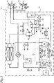
- FIG. 1 is a circuit diagram illustrating a configuration of a heat pump according to an embodiment of the present invention.
- the heat pump is a heat pump incorporated in an air conditioner.
- a solid line indicates a refrigerant channel (refrigerant pipe) in which refrigerant flows
- a broken line indicates an oil channel (oil pipe) in which refrigerating machine oil (oil) flows.
- components of the heat pump such as a filter, are not shown for simplicity of description.
- a heat pump 10 includes an outdoor unit 12 that exchanges heat with outdoor air and at least one indoor unit 14 that exchanges heat with indoor air.
- the heat pump 10 includes two indoor units 14.
- the outdoor unit 12 includes compressors 16A and 16B that compress refrigerant and discharge the compressed refrigerant, heat exchangers 18 that perform heat exchange between refrigerant and outdoor air, and a four-way valve 20.
- Each of the indoor units 14 includes a heat exchanger 22 that performs heat exchange between refrigerant and indoor air.
- the compressors 16A and 16B are driven by a gas engine 24.
- the two compressors 16A and 16B and the one gas engine 24 are mounted in the outdoor unit 12. At least one of the compressors 16A and 16B is selectively driven by one gas engine 24.
- the driving source of the compressors 16A and 16B is not limited to the gas engine 24, and may be a motor or a gasoline engine, for example.
- High-temperature and high-pressure gas refrigerant discharged from at least one of discharge ports 16aa and 16ba of the compressors 16A and 16B is directed to the heat exchangers 18 of the outdoor unit 12 or the heat exchangers 22 of the indoor units 14 by the four-way valve 20.
- the gas refrigerant discharged from the compressors 16A and 16B is sent to the heat exchangers 22 of the indoor units 14.
- the gas refrigerant is sent to the heat exchangers 18 of the outdoor unit 12.
- An oil separator 30 that separates oil included in refrigerant is disposed on a discharge path from the compressors 16A and 16B, that is, on a refrigerant channel between the discharge ports 16aa and 16ba of the compressors 16A and 16B and the four-way valve 20.
- the high-temperature and high-pressure gas refrigerant that is discharged from at least one of the compressors 16A and 16B and has passed through the four-way valve 20 (solid line) exchanges heat with indoor air in the heat exchanger 22 of at least one of the indoor units 14. That is, heat is transferred from the refrigerant to the indoor air through the heat exchanger 22. Consequently, the refrigerant becomes a low-temperature and high-pressure liquid state.
- Each of the indoor units 14 includes an expansion valve 32 whose opening degree is adjustable.
- the expansion valve 32 is disposed in the indoor unit 14 and is located between the heat exchanger 22 of the indoor unit 14 and the heat exchangers 18 of the outdoor unit 12 on the refrigerant channel. While the expansion valve 32 is open, refrigerant can pass through the heat exchanger 22 of the indoor unit 14. While the indoor unit 14 stops, the expansion valve 32 is closed. In the heating operation, the expansion valve 32 is fully open.
- the outdoor unit 12 includes a receiver 34.
- the receiver 34 is a buffer tank that temporarily stores low-temperature and high-pressure liquid refrigerant subjected to heat exchange with indoor air in the heat exchangers 22 of the indoor units 14 in the heating operation.
- the liquid refrigerant that has flowed from the heat exchangers 22 of the indoor units 14 flows into the receiver 34 through a check valve 36.
- the low-temperature and high-pressure liquid refrigerant in the receiver 34 is sent to the heat exchangers 18 of the outdoor unit 12.
- a check valve 38 and expansion valves 40 are provided on the refrigerant channel between the receiver 34 and the heat exchangers 18.
- the expansion valves 40 are expansion valves whose opening degrees are adjustable. In the heating operation, the opening degrees of the expansion valves 40 are adjusted in such a manner that the refrigerant superheating degree of a suction port 16ab or 16bb of the compressor 16A or 16B is a predetermined temperature or more.
- the refrigerant superheating degree of the suction port 16ab or 16bb is a difference between a saturated steam temperature determined from a pressure detected by a pressure sensor 68 and a temperature detected by a temperature sensor 66, and is controlled in such a manner that the detected temperature is higher than the saturated stem temperature by a predetermined temperature (e.g., 5°C) or more.
- the low-temperature and high-pressure liquid refrigerant that has flowed from the receiver 34 is expanded (subjected to pressure reduction) by the expansion valves 40 to be a low-temperature and low-pressure liquid state (mist state).
- the refrigerant superheating degree may be calculated by using a temperature detected by an (unillustrated) temperature sensor disposed on the refrigerant path downstream of a merging point with refrigerant that has passed through an evaporation assisting heat exchanger 64, instead of the temperature detected by the temperature sensor 66, depending on the operating state.
- the low-temperature and low-pressure liquid refrigerant that has passed through the expansion valves 40 exchanges heat with outdoor air in the heat exchangers 18 of the outdoor unit 12. That is, heat is transferred from the outdoor air to the refrigerant through the heat exchangers 18. Consequently, the refrigerant becomes a low-temperature and low-pressure gas state.
- the outdoor unit 12 also includes an accumulator 42.
- the accumulator 42 temporarily stores the low-temperature and low-pressure gas refrigerant subjected to heat exchange with outdoor air in the heat exchangers 18 of the outdoor unit 12.
- the accumulator 42 is disposed on a suction path of the compressors 16A and 16B (refrigerant channel between the suction ports 16ab and 16bb of the compressors 16A and 16B and the four-way valve 20).
- the low-temperature and low-pressure gas refrigerant in the accumulator 42 is sucked in at least one of the compressors 16A and 16B and is compressed therein. Consequently, the refrigerant becomes a high-temperature and high-pressure gas state, and in the heating operation, is sent to the heat exchangers 22 of the indoor units 14 again.
- a shut-off valve 62 is open in a normal air-conditioning operation.
- the shut-off valve 62 is closed in a period in which liquid refrigerant is present because of a rapid decrease of an air-conditioning load, such as a non-operating period or an initial stage of start-up, and thereby, the liquid refrigerant is stored in the accumulator 42.
- the heat pump 10 also includes the evaporation assisting heat exchanger 64 disposed in parallel with the heat exchangers 18 in a refrigerant flow in the heating operation.
- liquid refrigerant in the receiver 34 is caused to flow to the evaporation assisting heat exchanger 64.
- an expansion valve 70 whose opening degree is adjustable is disposed between the receiver 34 and the evaporation assisting heat exchanger 64.
- a control device (not shown) of the heat pump 10 opens the expansion valve 70 if the refrigerant superheating degree of the suction port 16ab or 16bb is the predetermined temperature or less.
- the expansion valve 70 When the expansion valve 70 is opened, at least a part of the liquid refrigerant flows from the receiver 34 toward the evaporation assisting heat exchanger 64 through the expansion valve 70 to be a low-temperature and low-pressure mist state.
- the mist refrigerant that has passed through the expansion valve 70 is heated in the evaporation assisting heat exchanger 64 by, for example, a high-temperature exhaust gas or cooling water of the gas engine 24 (i.e., waste heat of the gas engine 24).
- a high-temperature exhaust gas or cooling water of the gas engine 24 i.e., waste heat of the gas engine 24.
- the mist refrigerant that has flowed into the evaporation assisting heat exchanger 64 through the expansion valve 70 is changed to a high-temperature and low-pressure gas state.
- the high-temperature gas refrigerant heated by the evaporation assisting heat exchanger 64 comes to have a superheating degree higher than that of refrigerant that has passed through the heat exchangers 18, and is merged with the refrigerant channel between the four-way valve 20 and the accumulator 42.
- liquid refrigerant included in the gas refrigerant that has passed through the four-way valve 20 and returns to the compressors 16 is heated by the high-temperature gas refrigerant from the evaporation assisting heat exchanger 64 and is evaporated (gasified).
- refrigerant flowing into the accumulator 42 is substantially caused to be in a gas state.
- the refrigerant that has flowed from the heat exchangers 18 passes through a shut-off valve 50 and a check valve 52 and flows into the receiver 34.
- the shut-off valve 50 is closed in the heating operation.
- the refrigerant that has flowed from the heat exchangers 18 flows into the receiver 34 only through the shut-off valve 50 and the check valve 52, and in some cases, additionally through the expansion valves 40 and a check valve 54.
- the refrigerant that has flowed into the receiver 34 passes through a check valve 56 and then passes through the expansion valves 32 of the indoor units 14.
- the refrigerant is subjected to pressure reduction and becomes a low-temperature and low-pressure liquid state (mist state).
- the refrigerant that has passed through the expansion valves 32 passes through the heat exchangers 22 of the indoor units 14 and exchanges heat with indoor air therein. In this manner, the refrigerant takes heat from the indoor air (cools the indoor air). As a result, the refrigerant becomes a low-temperature and low-pressure gas state.
- the refrigerant that has flowed from the heat exchangers 22 passes through the four-way valve 20 and the accumulator 42, and returns to at least one of the compressors 16A and 16B.
- the heat pump 10 includes a cooling heat exchanger 58 for cooling refrigerant flowing from the receiver 34 toward the check valve 56.
- the cooling heat exchanger 58 is configured to perform heat exchange between the liquid refrigerant flowing from the receiver 34 toward the check valve 56 and mist refrigerant, that is, to cool the liquid refrigerant by mist refrigerant.
- This mist refrigerant is obtained by changing part of the liquid refrigerant flowing from the cooling heat exchanger 58 toward the check valve 56 into mist (reducing the pressure of the refrigerant) by using an expansion valve 60.
- the expansion valve 60 is a valve whose opening degree is adjustable in order to selectively cool liquid refrigerant with the cooling heat exchanger 58.
- the expansion valve 60 When the expansion valve 60 is at least partially opened by control of the expansion valve 60 by the control device (not shown) of the heat pump 10, part of liquid yet to pass through the check valve 56 after the cooling heat exchanger 58 passes through the expansion valve 60 to be changed into mist (subjected to pressure reduction).
- the mist refrigerant obtained by the expansion valve 60 flows into the cooling heat exchanger 58, takes heat from the liquid refrigerant that has flowed out of the receiver 34 and yet to pass through the check valve 56, and is thereby gasified.
- liquid refrigerant at a temperature lower than that in a state where the expansion valve 60 is closed flows into the heat exchangers 22 of the indoor units 14.
- the gas refrigerant that has taken heat from the liquid refrigerant that has flowed out of the receiver 34 and yet to pass through the check valve 56 is directly returned to the compressors 16A and 16B from the cooling heat exchanger 58.
- This gas refrigerant is used for evaporating liquid refrigerant stored in the accumulator 42. That is, by opening the shut-off valve 62, the liquid refrigerant in the accumulator 42 is mixed with gas refrigerant returning from the cooling heat exchanger 58 to the compressors 16A and 16B to be gasified, and is returned to the compressors 16A and 16B.
- the oil separator 30 separates (collects) oil from refrigerant discharged from at least one of the compressors 16A and 16B.
- the oil collected by the oil separator 30 is returned to the compressors 16A and 16B through an oil return channel 80.
- oil is directly returned to oil reservoirs of the compressors 16A and 16B or is returned while being mixed in refrigerant flowing into the suction ports 16ab and 16bb of the compressors 16A and 16B.
- the heat pump 10 includes the two compressors 16A and 16B.
- the oil return channel 80 is branched into a branch path 80A connected to the compressor 16A and a branch path 80B connected to the compressor 16B.
- the branch path 80A of the oil return channel 80 connected to the compressor 16A is provided with a shut-off valve 82A, a capillary 84A, a pressure sensor 86A, and a capillary 88A in this order from the oil separator 30.
- the branch path 80B of the oil return channel 80 connected to the compressor 16B is provided with a shut-off valve 82B, a capillary 84B, a pressure sensor 86B, and a capillary 88B in this order from the oil separator 30.
- Each of the shut-off valves 82A and 82B is kept open while the corresponding one of the compressors 16A and 16B is operating, and is kept closed while the corresponding one of the compressors 16A and 16B is stopped. In this manner, an appropriate amount of oil is supplied only to the operating compressor.
- the capillaries 84A, 84B, 88A, and 88B are pressure loss members that reduce the pressure of oil returning from the oil separator 30 to the compressors 16A and 16B. That is, the capillaries 84A, 84B, 88A, and 88B reduce the pressure of oil flowing in the oil return channel 80 under a pressure substantially equal to the discharge pressure of the compressors 16A and 16B. As long as a pressure loss occurs, the capillaries may be replaced by, for example, expansion valves.
- the pressure sensors 86A and 86B detect the pressure of oil in the corresponding branch paths 80A and 80B of the oil return channel 80. Based on the pressures detected by the pressure sensors 86A and 86B, the control device of the heat pump 10 detects an abnormality of the oil return channel 80. A method for detecting an abnormality of the oil return channel 80 will be described.
- the pressure sensor 86A detects the pressure of oil in a portion of the branch path 80A between the capillaries 84A and 88A.
- the pressure sensor 86B detects the pressure of oil in a portion of the branch path 80B between the capillaries 84B and 88B.
- the pressure in a portion of the oil return channel 80 upstream of the capillaries 84A and 84B is substantially equal to a discharge pressure P OUT of the compressors 16A and 16B.
- the pressure in a portion of the oil return channel 80 downstream of the capillaries 88A and 88B is substantially equal to a suction pressure P IN of the compressors 16A and 16B.
- the pressure sensors 86A and 86B detect a normal pressure value P N greater than the suction pressure P IN of the compressors 16A and 16B and less than the discharge pressure P OUT of the compressors 16A and 16B. Specifically, the pressure sensors 86A and 86B detect the normal pressure value P N based on pressure losses of the capillaries 84A, 84B, 88A, and 88B.
- the normal pressure value P N detected by the pressure sensors 86A and 86B when the oil return channel 80 is normal is substantially an intermediate value between the discharge pressure P OUT and the suction pressure P IN of the compressors 16A and 16B.
- the normal pressure value P N detected by the pressure sensors 86A and 86B when the oil return channel 80 is normal is near the suction pressure P IN .
- the pressure sensor 86A detects a pressure substantially equal to the discharge pressure P OUT of the compressors 16A and 16B.
- the pressure sensor 86B detects a pressure substantially equal to the suction pressure P IN of the compressors 16A and 16B.
- the discharge pressure P OUT of the compressors 16A and 16B is determined by a pressure sensor 90 that detects a pressure in the refrigerant channel between the discharge ports 1 6aa and 16ba of the compressors 16A and 16B and the oil separator 30.
- the suction pressure P IN of the compressors 16A and 1 6B is determined by the pressure sensor 68 that detects a pressure in the refrigerant channel between the four-way valve 20 and the accumulator 42.
- the control device of the heat pump 10 determines whether an abnormality occurs in the oil return channel 80 or not, based on the pressures detected by the pressure sensors 86A and 86B. That is, the control device determines whether the pressures detected by the pressure sensors 86A and 86B exceed the suction pressure P IN of the compressors 16A and 16B and less than the discharge pressure P OUT of the compressors 16A and 16B.
- the control device of the heat pump 10 increases the outputs of the compressors 16A and 16B (permits an increase in outputs) as necessary.
- the control device of the heat pump 10 restricts an increase in the outputs of the compressors 16A and 16B and maintains operation of the compressors 16A and 16B.
- the control device stops the compressors 16A and 16B and issues a notification of an abnormality of the oil return channel 80 as a warning.
- an abnormality of the oil return channel 80 can be accurately detected at an early stage.
- the abnormality of the oil return channel 80 can be accurately detected at an early stage, as compared to a case where the abnormality is detected based on an oil temperature.
- the heat pump 10 includes the two compressors 16A and 16B in the embodiment, the present invention is not limited to this example.
- the heat pump may include one compressor.
- the shut-off valve on the oil return channel can be omitted. That is, if a plurality of compressors are provided, a shut-off valve is needed for selectively returning oil to an operating compressor. However, since only one compressor is provided in this case, no shut-off valve is needed.
- the heat pump 10 is an air conditioner that controls the temperature of indoor air as a target of temperature adjustment, but the embodiment of the present invention is not limited to this example.
- the heat pump according to the embodiment of the present invention may be a chiller for adjusting the temperature of water using refrigerant.
- the heat pump broadly includes: a compressor that compresses refrigerant and discharges the compressed refrigerant; an oil separator that separates oil from the refrigerant discharged from the compressor; an oil return channel that returns the oil separated by the oil separator to the compressor; a pressure sensor that detects a pressure in the oil return channel; first and second pressure loss members disposed in portions of the oil return channel at an oil separator side and a compressor side relative to the pressure sensor; and a control device that controls the compressor to increase an output of the compressor in a case where a pressure detected by the pressure sensor exceeds a suction pressure of the compressor and less than a discharge pressure of the compressor.
- the present invention is applicable to a heat pump including an oil separator that collects oil included in refrigerant discharged from a compressor and returns the collected oil to the compressor.
Landscapes
- Engineering & Computer Science (AREA)
- Mechanical Engineering (AREA)
- General Engineering & Computer Science (AREA)
- Physics & Mathematics (AREA)
- Thermal Sciences (AREA)
- Chemical & Material Sciences (AREA)
- Analytical Chemistry (AREA)
- Power Engineering (AREA)
- Life Sciences & Earth Sciences (AREA)
- Sustainable Development (AREA)
- Air Conditioning Control Device (AREA)
- Compressor (AREA)
Abstract
Description
- The present invention relates to a heat pump.
- In a heat pump that has been known to date, an oil separator collects refrigerating machine oil (oil) included in refrigerant discharged from a compressor and the collected oil is returned to the compressor. For example, a heat pump described in Patent Literature 1 (PTL 1) includes an oil return channel for returning oil collected by an oil separator to a compressor. The oil return channel includes a shut-off valve and a capillary. The oil return channel is provided with a pressure sensor that detects an oil pressure in a portion of the oil return channel at an oil separator side relative to the capillary. The heat pump described in PTL 1 is configured to detect an abnormality of the oil return channel such as breakage or clogging by comparing the pressure detected by the pressure sensor with a discharge pressure or a suction pressure of the compressor.
- PTL 1: Japanese Patent Application Laid-Open No.
2012-82992 - In the heat pump described in PTL 1, however, the pressure sensor can detect a pressure near the discharge pressure of the compressor both when oil normally flows in the oil return channel and when the capillary is clogged. This leads to a low accuracy in detecting an abnormality of the oil return channel.
- Instead, detection of an abnormality of the oil return channel is carried out based on a comparison between the temperature of oil in the oil return channel and the discharge temperature of the compressor. If the temperature of oil in the oil return channel is near the discharge temperature of the compressor, the oil return channel is determined to be normal.
- In this case, however, if a large amount of oil is stored in the oil separator at start-up of the heat pump, it takes time for the oil temperature in the oil return channel to reach a temperature near the discharge temperature of the compressor. Thus, for a while after the start-up of the heat pump, the oil return channel is determined to be abnormal, although oil normally flows in the oil return channel. Thus, for a while after the start-up of the heat pump, abnormality determination of the oil return channel cannot be performed.
- In another known heat pump, a plurality of compressors are provided, and refrigerant streams discharged from the compressors are merged, and from the merged refrigerant, oil is collected by one oil separator. In this case, an oil return channel starts from the oil separator and is branched into a plurality of paths that are individually connected to the compressors. Each of the branch paths is provided with a shut-off valve and a temperature sensor. In this configuration, an abnormality of the oil return channel is detected based on a difference in oil temperature between the branch paths of the oil return channel.
- For example, in a configuration in which two compressors are provided and the oil return channel is branched into two paths, an abnormality of the oil return channel is detected base on the difference in oil temperature between the two branch paths. For example, while only one of the compressors operates, that is, while the shut-off valve on the branch path connected to the nonoperating compressor is closed and the shut-off valve on the branch path connected to the operating compressor is open, a temperature difference occurs between oil in the two branch paths. At this time, if no temperature difference occurs, there is an abnormality that the shut-off valve corresponding to the nonoperating compressor is not normally closed or the shut-off valve corresponding to the operating compressor is not normally open.
- It should be noted that residual heat of the compressor immediately after stopping its operation prevents the temperature of oil near this compressor from decreasing immediately. Thus, in a case where temperature sensors are disposed on portions of branch paths near the compressors, no temperature difference occurs for a while between the temperature detected by the temperature sensor corresponding to the operating compressor and the temperature detected by the temperature sensor corresponding to the compressor immediately after stopping its operation. Accordingly, determination of an abnormality of the oil return channel cannot be performed for a while after one of the compressors stops.
- It is therefore an object of an aspect of the present invention to accurately detect an abnormality of an oil return channel at an early stage in a heat pump in which oil in refrigerant discharged from a compressor is collected by an oil separator and the collected oil is returned to the compressor by using the oil return channel.
- To solve the technical problems described above, an aspect of the present invention provides a heat pump including:
- a compressor that compresses refrigerant and discharges the compressed refrigerant;
- an oil separator that separates oil from the refrigerant discharged from the compressor;
- an oil return channel that returns oil separated by the oil separator to the compressor;
- a pressure sensor that detects a pressure in the oil return channel; and
- first and second pressure loss members disposed in portions of the oil return channel at an oil separator side and a compressor side relative to the pressure sensor; and
- a control device that controls the compressor to increase an output of the compressor if a pressure detected by the pressure sensor exceeds a suction pressure of the compressor and less than a discharge pressure of the compressor.
- According to an aspect of the present invention, in a heat pump in which oil in refrigerant discharged from a compressor is collected by an oil separator and the collected oil is returned to the compressor by using an oil return channel, an abnormality of the oil return channel can be accurately detected at an early stage.
-
- [
FIG. 1 ] A circuit diagram illustrating a configuration of a heat pump according to an embodiment of the present invention. - [
FIG. 2 ] A circuit diagram illustrating a vicinity of an oil return channel. - An embodiment of the present invention will be described hereinafter with reference to the drawings.
-
FIG. 1 is a circuit diagram illustrating a configuration of a heat pump according to an embodiment of the present invention. In this embodiment, the heat pump is a heat pump incorporated in an air conditioner. InFIG. 1 , a solid line indicates a refrigerant channel (refrigerant pipe) in which refrigerant flows, and a broken line indicates an oil channel (oil pipe) in which refrigerating machine oil (oil) flows. In the circuit diagram illustrated inFIG. 1 , components of the heat pump, such as a filter, are not shown for simplicity of description. - As illustrated in
FIG. 1 , aheat pump 10 includes anoutdoor unit 12 that exchanges heat with outdoor air and at least oneindoor unit 14 that exchanges heat with indoor air. In this embodiment, theheat pump 10 includes twoindoor units 14. - The
outdoor unit 12 includescompressors heat exchangers 18 that perform heat exchange between refrigerant and outdoor air, and a four-way valve 20. Each of theindoor units 14 includes aheat exchanger 22 that performs heat exchange between refrigerant and indoor air. - The
compressors gas engine 24. In this embodiment, the twocompressors gas engine 24 are mounted in theoutdoor unit 12. At least one of thecompressors gas engine 24. The driving source of thecompressors gas engine 24, and may be a motor or a gasoline engine, for example. - High-temperature and high-pressure gas refrigerant discharged from at least one of discharge ports 16aa and 16ba of the
compressors heat exchangers 18 of theoutdoor unit 12 or theheat exchangers 22 of theindoor units 14 by the four-way valve 20. In a heating operation, the gas refrigerant discharged from thecompressors heat exchangers 22 of theindoor units 14. On the other hand, in a cooling operation, the gas refrigerant is sent to theheat exchangers 18 of theoutdoor unit 12. - An
oil separator 30 that separates oil included in refrigerant is disposed on a discharge path from thecompressors compressors way valve 20. - In the heating operation, the high-temperature and high-pressure gas refrigerant that is discharged from at least one of the
compressors heat exchanger 22 of at least one of theindoor units 14. That is, heat is transferred from the refrigerant to the indoor air through theheat exchanger 22. Consequently, the refrigerant becomes a low-temperature and high-pressure liquid state. - Each of the
indoor units 14 includes anexpansion valve 32 whose opening degree is adjustable. Theexpansion valve 32 is disposed in theindoor unit 14 and is located between theheat exchanger 22 of theindoor unit 14 and theheat exchangers 18 of theoutdoor unit 12 on the refrigerant channel. While theexpansion valve 32 is open, refrigerant can pass through theheat exchanger 22 of theindoor unit 14. While theindoor unit 14 stops, theexpansion valve 32 is closed. In the heating operation, theexpansion valve 32 is fully open. - The
outdoor unit 12 includes areceiver 34. Thereceiver 34 is a buffer tank that temporarily stores low-temperature and high-pressure liquid refrigerant subjected to heat exchange with indoor air in theheat exchangers 22 of theindoor units 14 in the heating operation. The liquid refrigerant that has flowed from theheat exchangers 22 of theindoor units 14 flows into thereceiver 34 through acheck valve 36. - In the heating operation, the low-temperature and high-pressure liquid refrigerant in the
receiver 34 is sent to theheat exchangers 18 of theoutdoor unit 12. Acheck valve 38 andexpansion valves 40 are provided on the refrigerant channel between thereceiver 34 and theheat exchangers 18. Theexpansion valves 40 are expansion valves whose opening degrees are adjustable. In the heating operation, the opening degrees of theexpansion valves 40 are adjusted in such a manner that the refrigerant superheating degree of a suction port 16ab or 16bb of thecompressor pressure sensor 68 and a temperature detected by atemperature sensor 66, and is controlled in such a manner that the detected temperature is higher than the saturated stem temperature by a predetermined temperature (e.g., 5°C) or more. The low-temperature and high-pressure liquid refrigerant that has flowed from thereceiver 34 is expanded (subjected to pressure reduction) by theexpansion valves 40 to be a low-temperature and low-pressure liquid state (mist state). The refrigerant superheating degree may be calculated by using a temperature detected by an (unillustrated) temperature sensor disposed on the refrigerant path downstream of a merging point with refrigerant that has passed through an evaporation assistingheat exchanger 64, instead of the temperature detected by thetemperature sensor 66, depending on the operating state. - In the heating operation, the low-temperature and low-pressure liquid refrigerant that has passed through the
expansion valves 40 exchanges heat with outdoor air in theheat exchangers 18 of theoutdoor unit 12. That is, heat is transferred from the outdoor air to the refrigerant through theheat exchangers 18. Consequently, the refrigerant becomes a low-temperature and low-pressure gas state. - The
outdoor unit 12 also includes anaccumulator 42. In the heating operation, theaccumulator 42 temporarily stores the low-temperature and low-pressure gas refrigerant subjected to heat exchange with outdoor air in theheat exchangers 18 of theoutdoor unit 12. Theaccumulator 42 is disposed on a suction path of thecompressors compressors - The low-temperature and low-pressure gas refrigerant in the
accumulator 42 is sucked in at least one of thecompressors heat exchangers 22 of theindoor units 14 again. - Since only the gas refrigerant is generally caused to flow into the
accumulator 42 by controlling the opening degree of theexpansion valves 40 or theexpansion valve 32 described later, a shut-offvalve 62 is open in a normal air-conditioning operation. The shut-offvalve 62 is closed in a period in which liquid refrigerant is present because of a rapid decrease of an air-conditioning load, such as a non-operating period or an initial stage of start-up, and thereby, the liquid refrigerant is stored in theaccumulator 42. - The
heat pump 10 also includes the evaporation assistingheat exchanger 64 disposed in parallel with theheat exchangers 18 in a refrigerant flow in the heating operation. - In a case where the refrigerant superheating degree of the suction port 16ab or 16bb does not increase to the predetermined temperature or more only by heat exchange of the
heat exchangers 18, such as a case where the outdoor air temperature is less than 0°C, liquid refrigerant in thereceiver 34 is caused to flow to the evaporation assistingheat exchanger 64. To cause the refrigerant to flow in this direction, anexpansion valve 70 whose opening degree is adjustable is disposed between thereceiver 34 and the evaporation assistingheat exchanger 64. - A control device (not shown) of the
heat pump 10 opens theexpansion valve 70 if the refrigerant superheating degree of the suction port 16ab or 16bb is the predetermined temperature or less. - When the
expansion valve 70 is opened, at least a part of the liquid refrigerant flows from thereceiver 34 toward the evaporation assistingheat exchanger 64 through theexpansion valve 70 to be a low-temperature and low-pressure mist state. - The mist refrigerant that has passed through the
expansion valve 70 is heated in the evaporation assistingheat exchanger 64 by, for example, a high-temperature exhaust gas or cooling water of the gas engine 24 (i.e., waste heat of the gas engine 24). In this manner, the mist refrigerant that has flowed into the evaporation assistingheat exchanger 64 through theexpansion valve 70 is changed to a high-temperature and low-pressure gas state. The high-temperature gas refrigerant heated by the evaporation assistingheat exchanger 64 comes to have a superheating degree higher than that of refrigerant that has passed through theheat exchangers 18, and is merged with the refrigerant channel between the four-way valve 20 and theaccumulator 42. In this manner, liquid refrigerant included in the gas refrigerant that has passed through the four-way valve 20 and returns to the compressors 16 is heated by the high-temperature gas refrigerant from the evaporation assistingheat exchanger 64 and is evaporated (gasified). As a result, refrigerant flowing into theaccumulator 42 is substantially caused to be in a gas state. - On the other hand, in a cooling operation, high-temperature and high-pressure gas refrigerant discharged from at least one of the
compressors heat exchangers 18 of theoutdoor unit 12 through the four-way valve 20 (indicated by chain double-dashed lines). Through heat exchange with outdoor air in theheat exchangers 18, the gas refrigerant becomes a low-temperature and high-pressure liquid state. - The refrigerant that has flowed from the
heat exchangers 18 passes through a shut-offvalve 50 and acheck valve 52 and flows into thereceiver 34. The shut-offvalve 50 is closed in the heating operation. - In the cooling operation, the refrigerant that has flowed from the
heat exchangers 18 flows into thereceiver 34 only through the shut-offvalve 50 and thecheck valve 52, and in some cases, additionally through theexpansion valves 40 and acheck valve 54. - In the cooling operation, the refrigerant that has flowed into the
receiver 34 passes through acheck valve 56 and then passes through theexpansion valves 32 of theindoor units 14. By the passage through theexpansion valves 32, the refrigerant is subjected to pressure reduction and becomes a low-temperature and low-pressure liquid state (mist state). - The refrigerant that has passed through the
expansion valves 32 passes through theheat exchangers 22 of theindoor units 14 and exchanges heat with indoor air therein. In this manner, the refrigerant takes heat from the indoor air (cools the indoor air). As a result, the refrigerant becomes a low-temperature and low-pressure gas state. The refrigerant that has flowed from theheat exchangers 22 passes through the four-way valve 20 and theaccumulator 42, and returns to at least one of thecompressors - To increase a cooling efficiency, the
heat pump 10 includes acooling heat exchanger 58 for cooling refrigerant flowing from thereceiver 34 toward thecheck valve 56. - The
cooling heat exchanger 58 is configured to perform heat exchange between the liquid refrigerant flowing from thereceiver 34 toward thecheck valve 56 and mist refrigerant, that is, to cool the liquid refrigerant by mist refrigerant. This mist refrigerant is obtained by changing part of the liquid refrigerant flowing from thecooling heat exchanger 58 toward thecheck valve 56 into mist (reducing the pressure of the refrigerant) by using anexpansion valve 60. Theexpansion valve 60 is a valve whose opening degree is adjustable in order to selectively cool liquid refrigerant with thecooling heat exchanger 58. - When the
expansion valve 60 is at least partially opened by control of theexpansion valve 60 by the control device (not shown) of theheat pump 10, part of liquid yet to pass through thecheck valve 56 after thecooling heat exchanger 58 passes through theexpansion valve 60 to be changed into mist (subjected to pressure reduction). The mist refrigerant obtained by theexpansion valve 60 flows into thecooling heat exchanger 58, takes heat from the liquid refrigerant that has flowed out of thereceiver 34 and yet to pass through thecheck valve 56, and is thereby gasified. As a result, liquid refrigerant at a temperature lower than that in a state where theexpansion valve 60 is closed, flows into theheat exchangers 22 of theindoor units 14. - On the other hand, the gas refrigerant that has taken heat from the liquid refrigerant that has flowed out of the
receiver 34 and yet to pass through thecheck valve 56, is directly returned to thecompressors cooling heat exchanger 58. This gas refrigerant is used for evaporating liquid refrigerant stored in theaccumulator 42. That is, by opening the shut-offvalve 62, the liquid refrigerant in theaccumulator 42 is mixed with gas refrigerant returning from thecooling heat exchanger 58 to thecompressors compressors - The foregoing description is schematically directed to components of the
heat pump 10 related to refrigerant. Now, a configuration of theheat pump 10 related to oil will be described with reference toFIG. 2 . - As described above, the
oil separator 30 separates (collects) oil from refrigerant discharged from at least one of thecompressors oil separator 30 is returned to thecompressors oil return channel 80. For example, oil is directly returned to oil reservoirs of thecompressors compressors - In this embodiment, the
heat pump 10 includes the twocompressors oil return channel 80 is branched into abranch path 80A connected to thecompressor 16A and abranch path 80B connected to thecompressor 16B. - The
branch path 80A of theoil return channel 80 connected to thecompressor 16A is provided with a shut-offvalve 82A, acapillary 84A, a pressure sensor 86A, and a capillary 88A in this order from theoil separator 30. On the other hand, thebranch path 80B of theoil return channel 80 connected to thecompressor 16B is provided with a shut-offvalve 82B, a capillary 84B, apressure sensor 86B, and a capillary 88B in this order from theoil separator 30. - Each of the shut-off
valves compressors compressors - The
capillaries oil separator 30 to thecompressors capillaries oil return channel 80 under a pressure substantially equal to the discharge pressure of thecompressors - The
pressure sensors 86A and 86B detect the pressure of oil in thecorresponding branch paths oil return channel 80. Based on the pressures detected by thepressure sensors 86A and 86B, the control device of theheat pump 10 detects an abnormality of theoil return channel 80. A method for detecting an abnormality of theoil return channel 80 will be described. - As illustrated in
FIG. 2 , the pressure sensor 86A detects the pressure of oil in a portion of thebranch path 80A between thecapillaries pressure sensor 86B detects the pressure of oil in a portion of thebranch path 80B between thecapillaries - In a case where the
compressors oil return channel 80, the pressure in a portion of theoil return channel 80 upstream of thecapillaries capillaries compressors - On the other hand, in the case where the
compressors oil return channel 80, the pressure in a portion of theoil return channel 80 downstream of thecapillaries branch path 80A between the capillary 88A and thecompressor 16A and a portion of thebranch path 80B between the capillary 88B and thecompressor 16B) is substantially equal to a suction pressure PIN of thecompressors - Thus, in the case where the
compressors oil return channel 80 is normal), thepressure sensors 86A and 86B detect a normal pressure value PN greater than the suction pressure PIN of thecompressors compressors pressure sensors 86A and 86B detect the normal pressure value PN based on pressure losses of thecapillaries - For example, in a case where the
capillaries pressure sensors 86A and 86B when theoil return channel 80 is normal is substantially an intermediate value between the discharge pressure POUT and the suction pressure PIN of thecompressors - In a case where pressure losses of the
capillaries oil separator 30 side are larger than pressure losses of thecapillaries compressors pressure sensors 86A and 86B when theoil return channel 80 is normal is near the suction pressure PIN. - In a case where the pressure detected by at least of one of the
pressure sensors 86A and 86B is not the normal pressure value PN but near the discharge pressure POUT or the suction pressure PIN, this detection result suggests the possibility of occurrence of an abnormality in theoil return channel 80. - For example, in a case where the
capillary 88A is clogged, the pressure sensor 86A detects a pressure substantially equal to the discharge pressure POUT of thecompressors valve 82B is not open, for example, thepressure sensor 86B detects a pressure substantially equal to the suction pressure PIN of thecompressors - Thus, based on the pressures detected by the
pressure sensors 86A and 86B, not only detection of normality or abnormality of theoil return channel 80 but also specification to some degree of a reason of a possible abnormality can be performed. - The discharge pressure POUT of the
compressors pressure sensor 90 that detects a pressure in the refrigerant channel between the discharge ports 1 6aa and 16ba of thecompressors oil separator 30. - On the other hand, the suction pressure PIN of the
compressors 16A and 1 6B is determined by thepressure sensor 68 that detects a pressure in the refrigerant channel between the four-way valve 20 and theaccumulator 42. - The control device of the
heat pump 10 determines whether an abnormality occurs in theoil return channel 80 or not, based on the pressures detected by thepressure sensors 86A and 86B. That is, the control device determines whether the pressures detected by thepressure sensors 86A and 86B exceed the suction pressure PIN of thecompressors compressors - If the
oil return channel 80 is normal (i.e., if the pressures detected by thepressure sensors 86A and 86B exceed the suction pressure PIN of thecompressors compressors heat pump 10 increases the outputs of thecompressors - On the other hand, while an abnormality of the
oil return channel 80 is detected (i.e., if the pressures detected by thepressure sensors 86A and 86B neither exceed the suction pressure PIN of thecompressors compressors heat pump 10 restricts an increase in the outputs of thecompressors compressors compressors oil return channel 80 as a warning. - In the foregoing embodiment, in the
heat pump 10 in which oil in refrigerant discharged from thecompressors oil separator 30 and the collected oil is returned to thecompressors oil return channel 80, an abnormality of theoil return channel 80 can be accurately detected at an early stage. - That is, as described above, since an abnormality of the
oil return channel 80 is detected based on the pressure of oil in theoil return channel 80, the abnormality of theoil return channel 80 can be accurately detected at an early stage, as compared to a case where the abnormality is detected based on an oil temperature. - The present invention has been described using the embodiment, but is not limited to the embodiment described above.
- For example, although the
heat pump 10 includes the twocompressors - In addition, in the embodiment, for example, the
heat pump 10 is an air conditioner that controls the temperature of indoor air as a target of temperature adjustment, but the embodiment of the present invention is not limited to this example. The heat pump according to the embodiment of the present invention may be a chiller for adjusting the temperature of water using refrigerant. That is, the heat pump according to an aspect of the present invention broadly includes: a compressor that compresses refrigerant and discharges the compressed refrigerant; an oil separator that separates oil from the refrigerant discharged from the compressor; an oil return channel that returns the oil separated by the oil separator to the compressor; a pressure sensor that detects a pressure in the oil return channel; first and second pressure loss members disposed in portions of the oil return channel at an oil separator side and a compressor side relative to the pressure sensor; and a control device that controls the compressor to increase an output of the compressor in a case where a pressure detected by the pressure sensor exceeds a suction pressure of the compressor and less than a discharge pressure of the compressor. - The present invention is applicable to a heat pump including an oil separator that collects oil included in refrigerant discharged from a compressor and returns the collected oil to the compressor.
- The present disclosure has been fully described in relation to a preferred embodiment with reference to the accompanying drawings, but it is obvious for those skilled in the art to which the present invention pertains that various modifications and changes are possible. Such modifications and changes, unless they depart from the scope of the present invention as set forth in a claim attached hereto, shall be understood as to be encompassed by the present invention.
- The disclosed contents of the specification, drawings, and claim of Japanese Patent Application Laid-Open No.
2015-53178 -
- 10
- heat pump
- 16
- compressor
- 30
- oil separator
- 80
- oil return channel
- 84A
- first pressure loss member (capillary)
- 84B
- first pressure loss member (capillary)
- 86A
- pressure sensor
- 86B
- pressure sensor
- 88A
- second pressure loss member (capillary)
- 88B
- second pressure loss member (capillary)
Claims (1)
- A heat pump comprising:a compressor that compresses refrigerant and discharges the compressed refrigerant;an oil separator that separates oil from the refrigerant discharged from the compressor;an oil return channel that returns the oil separated by the oil separator to the compressor;a pressure sensor that detects a pressure in the oil return channel;first and second pressure loss members disposed in portions of the oil return channel at an oil separator side and a compressor side relative to the pressure sensor; anda control device that controls the compressor to increase an output of the compressor in a case where a pressure detected by the pressure sensor exceeds a suction pressure of the compressor and less than a discharge pressure of the compressor.
Applications Claiming Priority (2)
| Application Number | Priority Date | Filing Date | Title |
|---|---|---|---|
| JP2015053178A JP6318107B2 (en) | 2015-03-17 | 2015-03-17 | heat pump |
| PCT/JP2016/057840 WO2016148079A1 (en) | 2015-03-17 | 2016-03-11 | Heat pump |
Publications (2)
| Publication Number | Publication Date |
|---|---|
| EP3273180A1 true EP3273180A1 (en) | 2018-01-24 |
| EP3273180A4 EP3273180A4 (en) | 2018-11-07 |
Family
ID=56920086
Family Applications (1)
| Application Number | Title | Priority Date | Filing Date |
|---|---|---|---|
| EP16764909.4A Withdrawn EP3273180A4 (en) | 2015-03-17 | 2016-03-11 | Heat pump |
Country Status (6)
| Country | Link |
|---|---|
| US (1) | US10641530B2 (en) |
| EP (1) | EP3273180A4 (en) |
| JP (1) | JP6318107B2 (en) |
| KR (1) | KR101992039B1 (en) |
| CN (1) | CN108027175B (en) |
| WO (1) | WO2016148079A1 (en) |
Families Citing this family (9)
| Publication number | Priority date | Publication date | Assignee | Title |
|---|---|---|---|---|
| JP6937831B2 (en) * | 2016-09-22 | 2021-09-22 | キャリア コーポレイションCarrier Corporation | Control method of freezing unit for transportation |
| JP6946163B2 (en) * | 2017-12-19 | 2021-10-06 | 三菱重工サーマルシステムズ株式会社 | Oil pump controller, control method, and control program and turbo chiller |
| JP7649773B2 (en) | 2019-08-06 | 2025-03-21 | ダウ グローバル テクノロジーズ エルエルシー | Multilayer film having at least three layers and method for producing same - Patents.com |
| US11969976B2 (en) | 2019-08-06 | 2024-04-30 | Dow Global Technologies Llc | Multilayer films that include at least five layers and methods of producing the same |
| ES2938408T3 (en) | 2019-08-06 | 2023-04-10 | Dow Global Technologies Llc | Multilayer films comprising polyethylene and barrier layers and methods for producing the same |
| MX2020008168A (en) | 2019-08-06 | 2021-02-08 | Dow Global Technologies Llc | Polyethylene compositions. |
| CN110749126A (en) * | 2019-11-14 | 2020-02-04 | 珠海格力电器股份有限公司 | Compressor assembly and air conditioning system with same |
| MX2022008119A (en) | 2019-12-31 | 2022-07-21 | Dow Global Technologies Llc | Polyethylene compositions. |
| US11933527B2 (en) * | 2020-02-27 | 2024-03-19 | Heatcraft Refrigeration Products Llc | Cooling system with oil return to accumulator |
Family Cites Families (13)
| Publication number | Priority date | Publication date | Assignee | Title |
|---|---|---|---|---|
| US5067326A (en) * | 1979-07-31 | 1991-11-26 | Alsenz Richard H | Method and apparatus for controlling capacity of a multiple-stage cooling system |
| JPS6363659U (en) * | 1986-10-14 | 1988-04-27 | ||
| JPH01152819U (en) * | 1988-04-13 | 1989-10-20 | ||
| JPH0452466A (en) * | 1990-06-18 | 1992-02-20 | Daikin Ind Ltd | Refrigerator and operation controller therefor |
| US5724821A (en) * | 1996-06-28 | 1998-03-10 | Carrier Corporation | Compressor oil pressure control method |
| JPH11107966A (en) * | 1997-10-06 | 1999-04-20 | Mitsubishi Electric Corp | Air conditioner |
| JP3937884B2 (en) * | 2002-03-22 | 2007-06-27 | 三菱電機株式会社 | Refrigeration air conditioner |
| DE60332823D1 (en) * | 2002-04-08 | 2010-07-15 | Daikin Ind Ltd | COOLER |
| GB0716329D0 (en) * | 2007-08-21 | 2007-10-03 | Compair Uk Ltd | Improvements in compressors control |
| KR101280381B1 (en) * | 2009-11-18 | 2013-07-01 | 엘지전자 주식회사 | Heat pump |
| JP5631684B2 (en) * | 2010-10-07 | 2014-11-26 | ヤンマー株式会社 | air conditioner |
| JP2013024538A (en) * | 2011-07-26 | 2013-02-04 | Hitachi Appliances Inc | Refrigeration unit |
| JP5921425B2 (en) * | 2012-12-12 | 2016-05-24 | ヤンマー株式会社 | air conditioner |
-
2015
- 2015-03-17 JP JP2015053178A patent/JP6318107B2/en active Active
-
2016
- 2016-03-11 WO PCT/JP2016/057840 patent/WO2016148079A1/en not_active Ceased
- 2016-03-11 KR KR1020177025622A patent/KR101992039B1/en not_active Expired - Fee Related
- 2016-03-11 CN CN201680007063.7A patent/CN108027175B/en not_active Expired - Fee Related
- 2016-03-11 US US15/558,470 patent/US10641530B2/en active Active
- 2016-03-11 EP EP16764909.4A patent/EP3273180A4/en not_active Withdrawn
Also Published As
| Publication number | Publication date |
|---|---|
| US20180051704A1 (en) | 2018-02-22 |
| US10641530B2 (en) | 2020-05-05 |
| KR101992039B1 (en) | 2019-06-21 |
| CN108027175B (en) | 2020-04-28 |
| JP6318107B2 (en) | 2018-04-25 |
| WO2016148079A1 (en) | 2016-09-22 |
| JP2016173202A (en) | 2016-09-29 |
| EP3273180A4 (en) | 2018-11-07 |
| CN108027175A (en) | 2018-05-11 |
| KR20170117494A (en) | 2017-10-23 |
Similar Documents
| Publication | Publication Date | Title |
|---|---|---|
| US10641530B2 (en) | Heat pump | |
| AU2004267299B2 (en) | Refrigeration system | |
| EP2413065B1 (en) | Refrigerator | |
| EP3545243B1 (en) | A method for controlling a vapour compression system during gas bypass valve malfunction | |
| WO2009082367A1 (en) | Refrigerant system and method of operating the same | |
| EP2246650A1 (en) | Turbo-refrigerator, refrigerating system, and their control method | |
| JP2014145325A (en) | Air compressor | |
| WO2016014144A1 (en) | Heat pump with ejector | |
| KR20200118968A (en) | Air conditioning apparatus | |
| EP2321593B1 (en) | Improved operation of a refrigerant system | |
| EP3273185B1 (en) | Heat pump | |
| KR100876285B1 (en) | Gas Heat Pump System | |
| KR102872745B1 (en) | An air conditioning apparatus | |
| EP1471316A1 (en) | Reversible heat pump system | |
| CN101124442A (en) | refrigeration circuit | |
| US10816251B2 (en) | Heat pump | |
| EP2417405B1 (en) | Refrigerating circuit and method for controlling the oil distribution within the same | |
| GB2559899A (en) | Air-conditioning device | |
| KR20200134805A (en) | An air conditioning apparatus | |
| JP2006317024A (en) | Refrigeration equipment | |
| CN116734428A (en) | Start control method of air conditioner |
Legal Events
| Date | Code | Title | Description |
|---|---|---|---|
| STAA | Information on the status of an ep patent application or granted ep patent |
Free format text: STATUS: THE INTERNATIONAL PUBLICATION HAS BEEN MADE |
|
| PUAI | Public reference made under article 153(3) epc to a published international application that has entered the european phase |
Free format text: ORIGINAL CODE: 0009012 |
|
| STAA | Information on the status of an ep patent application or granted ep patent |
Free format text: STATUS: REQUEST FOR EXAMINATION WAS MADE |
|
| 17P | Request for examination filed |
Effective date: 20170914 |
|
| AK | Designated contracting states |
Kind code of ref document: A1 Designated state(s): AL AT BE BG CH CY CZ DE DK EE ES FI FR GB GR HR HU IE IS IT LI LT LU LV MC MK MT NL NO PL PT RO RS SE SI SK SM TR |
|
| AX | Request for extension of the european patent |
Extension state: BA ME |
|
| DAV | Request for validation of the european patent (deleted) | ||
| DAX | Request for extension of the european patent (deleted) | ||
| A4 | Supplementary search report drawn up and despatched |
Effective date: 20181008 |
|
| RIC1 | Information provided on ipc code assigned before grant |
Ipc: F25B 43/02 20060101ALI20181001BHEP Ipc: F25B 1/00 20060101AFI20181001BHEP Ipc: F25B 31/00 20060101ALI20181001BHEP Ipc: F25B 49/02 20060101ALI20181001BHEP Ipc: F25B 41/06 20060101ALI20181001BHEP |
|
| RAP1 | Party data changed (applicant data changed or rights of an application transferred) |
Owner name: YANMAR POWER TECHNOLOGY CO., LTD. |
|
| STAA | Information on the status of an ep patent application or granted ep patent |
Free format text: STATUS: EXAMINATION IS IN PROGRESS |
|
| 17Q | First examination report despatched |
Effective date: 20210309 |
|
| STAA | Information on the status of an ep patent application or granted ep patent |
Free format text: STATUS: THE APPLICATION IS DEEMED TO BE WITHDRAWN |
|
| 18D | Application deemed to be withdrawn |
Effective date: 20240202 |