EP3272950B1 - Work vehicle with abnormality detection system - Google Patents
Work vehicle with abnormality detection system Download PDFInfo
- Publication number
- EP3272950B1 EP3272950B1 EP16203450.8A EP16203450A EP3272950B1 EP 3272950 B1 EP3272950 B1 EP 3272950B1 EP 16203450 A EP16203450 A EP 16203450A EP 3272950 B1 EP3272950 B1 EP 3272950B1
- Authority
- EP
- European Patent Office
- Prior art keywords
- abnormality
- work
- work vehicle
- travelling
- early
- Prior art date
- Legal status (The legal status is an assumption and is not a legal conclusion. Google has not performed a legal analysis and makes no representation as to the accuracy of the status listed.)
- Active
Links
Images

Classifications
-
- G—PHYSICS
- G07—CHECKING-DEVICES
- G07C—TIME OR ATTENDANCE REGISTERS; REGISTERING OR INDICATING THE WORKING OF MACHINES; GENERATING RANDOM NUMBERS; VOTING OR LOTTERY APPARATUS; ARRANGEMENTS, SYSTEMS OR APPARATUS FOR CHECKING NOT PROVIDED FOR ELSEWHERE
- G07C5/00—Registering or indicating the working of vehicles
- G07C5/08—Registering or indicating performance data other than driving, working, idle, or waiting time, with or without registering driving, working, idle or waiting time
- G07C5/0841—Registering performance data
-
- E—FIXED CONSTRUCTIONS
- E02—HYDRAULIC ENGINEERING; FOUNDATIONS; SOIL SHIFTING
- E02F—DREDGING; SOIL-SHIFTING
- E02F9/00—Component parts of dredgers or soil-shifting machines, not restricted to one of the kinds covered by groups E02F3/00 - E02F7/00
- E02F9/26—Indicating devices
- E02F9/267—Diagnosing or detecting failure of vehicles
-
- A—HUMAN NECESSITIES
- A01—AGRICULTURE; FORESTRY; ANIMAL HUSBANDRY; HUNTING; TRAPPING; FISHING
- A01B—SOIL WORKING IN AGRICULTURE OR FORESTRY; PARTS, DETAILS, OR ACCESSORIES OF AGRICULTURAL MACHINES OR IMPLEMENTS, IN GENERAL
- A01B69/00—Steering of agricultural machines or implements; Guiding agricultural machines or implements on a desired track
- A01B69/007—Steering or guiding of agricultural vehicles, e.g. steering of the tractor to keep the plough in the furrow
-
- A—HUMAN NECESSITIES
- A01—AGRICULTURE; FORESTRY; ANIMAL HUSBANDRY; HUNTING; TRAPPING; FISHING
- A01B—SOIL WORKING IN AGRICULTURE OR FORESTRY; PARTS, DETAILS, OR ACCESSORIES OF AGRICULTURAL MACHINES OR IMPLEMENTS, IN GENERAL
- A01B76/00—Parts, details or accessories of agricultural machines or implements, not provided for in groups A01B51/00 - A01B75/00
-
- A—HUMAN NECESSITIES
- A01—AGRICULTURE; FORESTRY; ANIMAL HUSBANDRY; HUNTING; TRAPPING; FISHING
- A01D—HARVESTING; MOWING
- A01D41/00—Combines, i.e. harvesters or mowers combined with threshing devices
- A01D41/12—Details of combines
- A01D41/127—Control or measuring arrangements specially adapted for combines
- A01D41/1271—Control or measuring arrangements specially adapted for combines for measuring crop flow
-
- G—PHYSICS
- G05—CONTROLLING; REGULATING
- G05D—SYSTEMS FOR CONTROLLING OR REGULATING NON-ELECTRIC VARIABLES
- G05D1/00—Control of position, course, altitude or attitude of land, water, air or space vehicles, e.g. using automatic pilots
- G05D1/02—Control of position or course in two dimensions
- G05D1/021—Control of position or course in two dimensions specially adapted to land vehicles
- G05D1/0276—Control of position or course in two dimensions specially adapted to land vehicles using signals provided by a source external to the vehicle
-
- G—PHYSICS
- G07—CHECKING-DEVICES
- G07C—TIME OR ATTENDANCE REGISTERS; REGISTERING OR INDICATING THE WORKING OF MACHINES; GENERATING RANDOM NUMBERS; VOTING OR LOTTERY APPARATUS; ARRANGEMENTS, SYSTEMS OR APPARATUS FOR CHECKING NOT PROVIDED FOR ELSEWHERE
- G07C5/00—Registering or indicating the working of vehicles
- G07C5/008—Registering or indicating the working of vehicles communicating information to a remotely located station
-
- G—PHYSICS
- G07—CHECKING-DEVICES
- G07C—TIME OR ATTENDANCE REGISTERS; REGISTERING OR INDICATING THE WORKING OF MACHINES; GENERATING RANDOM NUMBERS; VOTING OR LOTTERY APPARATUS; ARRANGEMENTS, SYSTEMS OR APPARATUS FOR CHECKING NOT PROVIDED FOR ELSEWHERE
- G07C5/00—Registering or indicating the working of vehicles
- G07C5/08—Registering or indicating performance data other than driving, working, idle, or waiting time, with or without registering driving, working, idle or waiting time
- G07C5/0808—Diagnosing performance data
-
- G—PHYSICS
- G07—CHECKING-DEVICES
- G07C—TIME OR ATTENDANCE REGISTERS; REGISTERING OR INDICATING THE WORKING OF MACHINES; GENERATING RANDOM NUMBERS; VOTING OR LOTTERY APPARATUS; ARRANGEMENTS, SYSTEMS OR APPARATUS FOR CHECKING NOT PROVIDED FOR ELSEWHERE
- G07C5/00—Registering or indicating the working of vehicles
- G07C5/08—Registering or indicating performance data other than driving, working, idle, or waiting time, with or without registering driving, working, idle or waiting time
- G07C5/0816—Indicating performance data, e.g. occurrence of a malfunction
Definitions
- the present disclosure relates to a work vehicle having a function of determining an abnormality, based on signals sent from a group of sensors detecting states of a vehicle body and a work device.
- Document JP 10-155327 A discloses a combine.
- the combine computes, when an engine is started, a drive load, i.e., an idling load on the engine during no-load operation, based on results of detection by a rack position sensor and an engine speed sensor. If the idling load is outside a set range, the combine provides notification of an abnormality of the engine by blinking an engine lamp and sounding a buzzer simultaneously.
- a grain threshing unit is driven by operating a grain threshing clutch lever to engage a grain threshing clutch.
- the combine provides notification of an abnormality of the grain threshing unit by blinking a grain threshing lamp and sounding a buzzer simultaneously.
- This combine can detect the abnormality of the engine and the abnormality of the grain threshing unit and provide notification of the abnormalities through the buzzers and the lamps, but does not provide the notification to the outside.
- the combine Since the combine notifies an abnormality based on a determination whether a result of detection falls within a set range, a user is not able to promptly know the abnormality if the set range is not fully rigorous; however, the combine notifies abnormalities more than necessary if the set range is too rigorous.
- Document JP 2000-201104 A discloses a vehicle equipped with an information transmitter for recording maintenance information for the vehicle, and transmitting the maintenance information with a mobile phone, and also discloses a maintenance station for servicing this vehicle.
- the vehicle When detecting an abnormality on a vehicle state, the vehicle transmits information regarding this abnormality to the maintenance station.
- the maintenance station recognizes that the vehicle owned by a customer is required to be serviced, and notifies the customer through the vehicle for a corresponding action, such as the vehicle should be brought into the maintenance station, or the customer himself/herself is urged to service the vehicle.
- an abnormality found in the vehicle is notified to the maintenance station through the mobile phone, a location of the abnormality occurred in the vehicle is still unknown.
- a riding control machine is an autonomous travel vehicle equipped with a GPS and sensors for detecting information necessary for the vehicle to travel in an autonomous manner, such as a vehicle speed, an orientation, an engine speed, and a steering angle.
- This vehicle has a function of continuing an autonomous travelling operation by switching a navigation mode to a dead reckoning navigation mode or an inertial navigation mode if positional information cannot be obtained through the GPS or positional information obtained through the GPS is deteriorated in precision, and of aborting the autonomous travelling operation if a state where positional information cannot be obtained through the GPS extends for a predetermined time, a state where positional information obtained through the GPS is deteriorated in precision extends for a predetermined time, or a steering mechanism cannot be controlled.
- this riding control machine has no technique of combining an own position calculated using the GPS and an abnormality occurred in a vehicle.
- JP 2011-220104 A a current position of a loaned moving work vehicle, a value of a service meter, a fuel quantity, an engine speed, an engine cooling water temperature, a battery voltage, a discharge pressure of a hydraulic pump, an oil quantity, an abnormality (error code), an image captured by a camera, and the like are sent via a communication device to and displayed on a terminal device in a remote location, as moving body information.
- This feature controls the moving work vehicle that is away from the terminal device, and, if it is determined that the moving work vehicle is used in a harsh environment, notifies a user to whom the moving work vehicle is loaned about the determination.
- the document EP 1 441 077 A1 relates to a device for managing work machines such as construction machines.
- driver identification data for identifying a driver A is inputted at the operating start time of a work machine
- the inputted driver identification data, the operating time of the construction machine, and the time and date at which the driver identification data was inputted are transmitted from the work machine to a terminal device.
- the amount of time the construction machine was operated by the driver A is displayed on the terminal, and the work machine can be managed on the basis of this display content.
- service person identification data and attachment data can be entered and transmitted to the terminal device.
- a method of monitoring a fluid system of a mining machine including sensing a pressure level of a fluid in the fluid system of the mining machine to generate pressure level data; analyzing the pressure level data to detect pressure level deviations; determining at least one selected from the group of when a frequency of the pressure level deviations exceeds a predetermined frequency, and when the fluid pressure level fails to reach a threshold within a predetermined reaction time period; and outputting an alert in response to the determination
- a work vehicle according to claim 1 is provided.
- a work vehicle comprises an own position calculation unit that calculates, based on positioning data, an own position which is a position of the work vehicle, a group of travelling work state detection sensors that outputs detected signals indicating a travelling work state, an early abnormality determination unit that determines, as an early abnormality, an abnormality at an early stage, which causes trouble in travelling work, based on the detected signals and a first condition, an actual abnormality determination unit that determines, as an actual abnormality, the abnormality at an actual stage, based on the detected signals and a second condition which is more rigorous than the first condition, a first notification unit that externally provides a notification of the early abnormality, based on a result of determination of the early abnormality, a second notification unit that externally provides a notification of the actual abnormality, based on a result of determination of the actual abnormality, and an abnormality information generation unit that generates abnormality information which is a combination of one of or both the determined early abnormality and the determined actual abnormality with an own position at which the abnormality has
- an abnormality occurred in a work vehicle during travelling work may be determined and classified into an early abnormality which is an abnormality at an early stage, or an actual abnormality which is the abnormality at an actual stage and is further worsened from the early stage, and the early abnormality and the actual abnormality are externally notified. Therefore, a supervisor supervising the work vehicle externally receives notification of the early abnormality as a caution on the abnormality, for example, or the actual abnormality, a degree of which is further worsened from a degree of the early abnormality, as a warning on the abnormality, for example.
- One of or both the early abnormality and the actual abnormality is or are combined as abnormality information with the own position calculated when the abnormality has occurred.
- the supervisor of the work vehicle is present at a location from which the work vehicle cannot be seen or a position of the work vehicle cannot be identified, the supervisor is able to therefore know a location at where an abnormality has occurred, as well as is able to take a more appropriate action against the occurred abnormality.
- the work vehicle By investigating an abnormality occurred in a work vehicle during travelling, while taking into account a travel route along which the work vehicle has actually travelled, a cause of the abnormality and its countermeasure can be examined. To this end, generated abnormality information should be connected to travelling operations and recorded, and the record should be read later. Therefore, the work vehicle includes an abnormality information recording unit that records the abnormality information in line with a travel locus.
- a supervisor positioned away from the automatic travelling work vehicle or a driver operating another manned work vehicle is required to check a state of a travelling work, in particular, check if any abnormality occurs. Notifications of an early abnormality and an actual abnormality externally as described above are therefore particularly advantageous for such an automatic travelling work vehicle.
- the work vehicle includes an automatic travel control unit that generates, based on a difference between a predetermined target travel route and the own position, an automatic steering instruction for causing the work vehicle to travel along the target travel route, and notification information regarding the early abnormality and the actual abnormality is sent to a communication terminal held by a supervisor supervising an automatic travelling operation.
- This configuration allows the supervisor positioned away from the automatic travelling work vehicle or a driver operating another manned work vehicle to know promptly an abnormality occurred in the automatic travelling work vehicle, through the communication terminal.
- the supervisor is also able to know an abnormality occurred in the work vehicle even if the communication terminal is not held by the supervisor.
- the work vehicle includes an abnormality recovery processing unit that automatically executes an abnormality recovery process for resolving the abnormality, based on a result of determination of the early abnormality or the actual abnormality.
- This abnormality recovery processing function may also be executed while the work vehicle is operated manually by a driver.
- the abnormality recovery process includes, for example, a program for allowing the work vehicle to travel in a shortest distance toward a location at where fuel can be supplied if an abnormality relates to running short of fuel, a program for stopping the work vehicle and driving an engine at an appropriate engine speed if an abnormality relates to overheating, and a program for stopping the work vehicle and executing a filter regeneration process if an abnormality relates to excessive accumulation of particulate matter in a diesel particulate filter (DPF).
- DPF diesel particulate filter
- the abnormality recovery process includes a partial or complete stoppage of the automatic travelling operation.
- the abnormality recovery process includes an automatic travelling operation through which the work vehicle automatically approaches the one of the ridges.
- abnormality recovery processing unit may therefore be advantageous if a content of an abnormality recovery process is settable beforehand in accordance with a type of an abnormality.
- the work vehicle further comprises an abnormality information recording unit that records the abnormality information in line with a travel locus.
- the work vehicle may further comprise an automatic travel control unit that generates, based on a difference between a predetermined target travel route and the own position, an automatic steering instruction for causing the work vehicle to travel along the target travel route, wherein notification information regarding the early abnormality and the actual abnormality may be sent to a communication terminal held by a supervisor supervising an automatic travelling operation.
- an automatic travel control unit that generates, based on a difference between a predetermined target travel route and the own position, an automatic steering instruction for causing the work vehicle to travel along the target travel route, wherein notification information regarding the early abnormality and the actual abnormality may be sent to a communication terminal held by a supervisor supervising an automatic travelling operation.
- the work vehicle may further comprise an abnormality recovery processing unit that automatically executes an abnormality recovery process for resolving the abnormality, based on a result of determination of the early abnormality or the actual abnormality.
- the abnormality recovery process may include a partial or complete stoppage of the automatic travelling operation.
- the abnormality recovery process may include an automatic travelling operation through which the work vehicle automatically approaches the one of the ridges.
- a content of the abnormality recovery process may be settable beforehand in accordance with a type of the abnormality.
- the work vehicle is a tractor that travels and works in a field (work field) separated by ridges as boundaries.
- This tractor is provided with an operation unit 20 partitioned by a cabin 21 at a center of a vehicle body 1 supported by front wheels 11 and rear wheels 12.
- a work device 30 that is a rotary tilling machine is mounted via a hydraulic lifting mechanism 31.
- the front wheels 11 function as steering control wheels through which the tractor changes a travel direction when a steering angle of the steering control wheels is changed.
- the steering angle of the front wheels 11 is changed by an operation of a steering mechanism 13.
- the steering mechanism 13 includes a steering motor 14 for automatic steering.
- the front wheels 11 are steered by operating a steering wheel 22 disposed on the operation unit 20.
- An engine 4 is mounted in a front area of the vehicle body 1, and engine power is transmitted to the front wheels 11 and the rear wheels 12 via a transmission 15 including a multiple-transmission mechanism and a clutch mechanism.
- a fuel tank 23 for supplying fuel to the engine 4 is disposed under the cabin 21. The fuel tank 23 is attached with a residual fuel quantity sensor that detects a residual fuel quantity.
- a satellite positioning module 80 configured as a GNSS module is provided.
- a satellite antenna for receiving GPS signals and GNSS signals is attached at a ceiling area of the cabin 21.
- the satellite positioning module 80 may include an inertial navigation module incorporated with a gyro acceleration sensor and a magnetic director sensor for complementing satellite navigation.
- the inertial navigation module may also be provided in a different location from that of the satellite positioning module 80.
- Various sensors that output detected signals indicating a travelling work state of this work vehicle are further disposed around the vehicle body 1 and the work device 30.
- the engine 4 that is a diesel engine constitutes an engine unit EU attached with, for example, an exhaust pipe unit 40 for discharging exhaust gas from this engine 4, an exhaust gas purifier 41, a selective catalytic reduction (SCR) 42, and a separator 43.
- the exhaust gas purifier 41 includes a filter for collecting particulate matter contained in exhaust gas, i.e., a diesel particulate filter (DPF).
- DPF diesel particulate filter
- Exhaust gas from the engine 4 flows into a front end of the exhaust gas purifier 41, and exhaust gas treated by the exhaust gas purifier 41 flows from a rear end of the exhaust gas purifier 41.
- the exhaust gas flowed from the exhaust gas purifier 41 passes through the SCR 42. At that time, the SCR 42 sprays aqueous urea toward the exhaust gas to purify nitrogen oxide in the exhaust gas.
- a filter regeneration process is required to be performed to burn and remove the particulate matter when an accumulation amount (DPF accumulation amount) reaches a predetermined value.
- aqueous urea to be used in the SCR 42 is stored in an aqueous urea tank, the aqueous urea is required to be replenished when its residual quantity lowers below a predetermined value.
- a sensor for detecting the DPF accumulation amount and a sensor for detecting a residual aqueous urea quantity are disposed.
- the engine unit EU is further disposed with a sensor for detecting a water level in the separator 43 and a sensor for detecting an engine water temperature. In Fig. 2 , these sensors around the engine are collectively indicated as a group of engine system detection sensors 83.
- Fig. 3 illustrates a control system configured in this tractor.
- This control system has a function of controlling abnormalities on the tractor (work vehicle) that could occur during travelling works in fields (work fields).
- the controlling unit 5 is a core element of this control system, and includes an output processing unit 7A and an input processing unit 7B, which respectively function as input and output interfaces, and a communication processing unit 7C.
- the output processing unit 7A is connected with, for example, an engine controlling unit 70, a group of vehicle travel devices 71, a group of work devices 72, and a notification device 73.
- the engine controlling unit 70 controls various operation devices included in the engine unit EU based on control instructions sent through the output processing unit 7A, or based on an individual control program.
- the group of vehicle travel devices 71 includes the steering motor 14 and devices to be controlled for allowing the vehicle to travel normally, such as operation devices incorporated in the transmission 15.
- the group of work devices 72 includes, for example, a drive mechanism for the work device 30, and a lifting mechanism 31 that raises and lowers the work device 30.
- the notification device 73 includes a display, lamps, and a speaker, and is used to warn the driver and a supervisor of an abnormality occurred in a travelling work. Signals are transmitted between the notification device 73 and the output processing unit 7A in a wired or wireless manner.
- the communication processing unit 7C exchanges data with an external computer in conformity to a wireless communication standard and a wired communication standard.
- Fig. 3 shows a control computer 100 constituted as an external computer in a control center KS in a remote location, and a monitoring communication terminal 110 held by a supervisor supervising the work vehicle being unmanned operated.
- the input processing unit 7B is coupled to, for example, a group of travelling work state detection sensors 8, the satellite positioning module 80, an automatic/manual switch 85, and a touch panel 9.
- the group of travelling work state detection sensors 8 is a group of sensors for detecting various states of this tractor performing a travelling work (including switches and buttons).
- the group of travelling work state detection sensors 8 includes a group of travel system detection sensors 81, a group of work system detection sensors 82, and the group of engine system detection sensors 83.
- the group of travel system detection sensors 81 includes sensors for detecting vehicle body states and travel states including a vehicle speed, a transmission state, an inclination of the vehicle body, and a residual fuel quantity.
- the group of work system detection sensors 82 includes, for example, sensors for detecting a ground clearance and an inclination of the work device 30, and sensors for detecting workloads and the like.
- the group of engine system detection sensors 83 includes, for example, sensors for detecting an engine speed and an engine water temperature, a sensor for assuming or detecting a DPF accumulation amount, and sensors for detecting a residual SCR quantity (residual aqueous urea quantity) and a water level of the separator.
- the automatic/manual switch 85 is a switch that selects either an automatic steering mode for travelling with automatic steering or a manual steering mode for travelling with manual steering. For example, by operating the automatic/manual switch 85 while travelling, a mode of the work vehicle can be switched from the automatic travel (automatic steering) mode to the manual travel (manual steering) mode, and vice versa.
- the touch panel 9 cooperates with a liquid crystal display included in the notification device 73 to accept an entry of a user operation.
- the controlling unit 5 is configured to include an abnormality processing module 60 that is a core function unit for controlling abnormalities that could occur in the work vehicle during travelling work, in particular an unmanned travelling work.
- the controlling unit 5 also includes a travel control unit 50, a work control unit 53, an own position calculation unit 54, an unmanned/manned operation detection unit 55, a work field control unit 56, a route generation unit 57, and a notification unit 58.
- the controlling unit 5 is illustrated as a single unit in Fig. 3 in order to provide a simple description, the controlling unit 5 is normally divided into a plurality of subunits, and the subunits are connected in such a manner that data can be transmitted each other through an on-vehicle LAN or other communication lines.
- the travel control unit 50 for controlling the group of vehicle travel devices 71 includes a manual travel control unit 51 and an automatic travel control unit 52.
- the manual travel control unit 51 controls the group of vehicle travel devices 71.
- the automatic travel control unit 52 Based on a deviation between an own position and a target travel route, the automatic travel control unit 52 generates and outputs an automatic steering instruction to the steering motor 14 via the output processing unit 7A.
- the work control unit 53 provides control signals to the group of work devices 72.
- the own position calculation unit 54 calculates an own position.
- the unmanned/manned operation detection unit 55 determines whether the work vehicle is unmanned operated (no-driver operated) or manned operated based on a state signal sent from the automatic/manual switch 85. A determination as to whether the driver is seated on a driver's seat can also be made based on a state signal sent from a seat switch included in the group of travel system detection sensors 81.
- the notification unit 58 generates notification information (including a display signal, a voice signal, a lamp drive signal, and a buzzer drive signal) for externally notifying information regarding an early abnormality or an actual abnormality to the driver or the supervisor through the notification device 73 such as the display, the speaker, and the lamps.
- This notification unit 58 includes a first notification unit 581 and a second notification unit 582 each having different functions.
- the first notification unit 581 notifies the early abnormality outside the work vehicle.
- the second notification unit 582 notifies the actual abnormality outside the work vehicle.
- a message or an illustration may be used when a display signal is used as notification information.
- a notification of an early abnormality and a notification of an actual abnormality can be expressly distinguished.
- a lamp drive signal or a buzzer drive signal is used as notification information
- a notification of an early abnormality and a notification of an actual abnormality can be distinguished with a drive pattern of the lamps and the buzzer, such as different intermittent drive intervals, for example.
- a lamp drive signal is used as notification information, a format may be adopted, where a yellow lamp is driven to notify an early abnormality, whereas a red lamp is driven to notify an actual abnormality.
- the notification unit 58 can further transmit the above described notification information to the monitoring communication terminal 110 or an ordinary mobile phone through the communication processing unit 7C. Even when the tractor is automatically travelled and is not watched directly, the supervisor can promptly be notified of an abnormality occurred in the tractor being automatic travelled.
- the work field control unit 56 controls field information (work field information) that is information regarding the field in which the work vehicle works and travels.
- the field information includes data such as a map position, shape, and size of a field, as well as plant varieties.
- the field information can be downloaded from, for example, the control computer 100 disposed in the control center KS in the remote location or a farmer's home.
- the route generation unit 57 reads external shape data of the field, and generates a target travel route that fits to this field.
- This target travel route may be automatically generated based on basic initial parameters such as a start point and an end point entered by an operator, or may be automatically generated based on a simple route pattern entered by the operator.
- a configuration may be adopted, through which a target travel route itself is downloaded from the control computer 100.
- the target travel route obtained from the route generation unit 57 is developed in a memory, and used by the work vehicle to travel along the target travel route regardless of whether the work vehicle is operated in either the automatic travel (automatic steering) mode or the manual travel (manual steering) mode.
- the abnormality processing module 60 determines an abnormality that could cause trouble in travelling work, based on detected signals indicating a travelling work state, which are sent from the group of travelling work state detection sensors 8, and provides a result of determination of the abnormality to the notification unit 58.
- the abnormality processing module 60 includes an early abnormality determination unit 61, an actual abnormality determination unit 62, an abnormality information generation unit 63, an abnormality recovery processing unit 64, and an abnormality information recording unit 65.
- the early abnormality determination unit 61 determines, as an early abnormality, an abnormality at an early stage, which could cause trouble in travelling work, based on detected signals sent from the group of travelling work state detection sensors 8 and a first condition.
- the early abnormality determination unit 61 gives information about an event causing the early abnormality in the travelling work, for example, a rise in an engine water temperature, and a reduction in a residual fuel quantity, to the first notification unit 581.
- the actual abnormality determination unit 62 determines, as an actual abnormality, the abnormality at an actual stage, which is more serious than the early abnormality, based on detected signals sent from the group of travelling work state detection sensors 8 and a second condition that is more rigorous than the above described first condition.
- the actual abnormality determination unit 62 gives information about an event causing the actual abnormality in the travelling work to the second notification unit 582.
- the early abnormality determination unit 61 and the actual abnormality determination unit 62 determine various abnormalities in travelling work, and signals to be detected and used for determination vary depending on a type of abnormality.
- the first condition used for determining an early abnormality and the second condition used for determining an actual abnormality also vary depending on a type of a detected signal.
- the abnormality information generation unit 63 When the early abnormality determination unit 61 determines an early abnormality or when the actual abnormality determination unit 62 determines an actual abnormality, the abnormality information generation unit 63 generates, in a predetermined format, abnormality information combined with a content of the abnormality and a vehicle position at which the abnormality has occurred.
- the abnormality information recording unit 65 records the abnormality information generated by the abnormality information generation unit 63 in line with a travel locus recorded in a format created so as to conform to a travel locus calculated based on own positions of the work vehicle sequentially calculated by the own position calculation unit 54.
- the recorded abnormality information is sent to the control computer 100 in the control center KS with a real-time process or a batch process for use in future maintenance and inspection control of the tractor.
- An abnormality control first may notify an abnormality only when an early abnormality is determined, and, after that, when the abnormality worsens to an extent that the abnormality is determined as an actual abnormality, aborts a travelling work itself.
- An abnormality control will now be described herein.
- the abnormality recovery processing unit 64 Based on an early abnormality determined by the early abnormality determination unit 61 or an actual abnormality determined by the actual abnormality determination unit 62, the abnormality recovery processing unit 64 automatically executes any of the above described abnormality recovery processes for resolving the abnormality. Since abnormalities include abnormalities relating to various failure events, such as travel system abnormalities, work system abnormalities, and engine system abnormalities, the abnormality recovery processing unit 64 stores procedures for abnormality recovery processes associated with early abnormalities and actual abnormalities regarding the aforementioned abnormalities. Abnormality recovery processes often vary depending on whether the tractor is in automatic travelling (unmanned travelling) or manual travelling (manned travelling). In automatic travelling, if the supervisor fails to find a notification on an abnormality, the abnormality becomes serious.
- an abnormality recovery process is provided to partially or completely abort the automatic travelling if a particular abnormality has been determined.
- another abnormality recovery process is provided to cause the tractor to automatically travel, approach a ridge, and wait for supply. If a particular abnormality occurs, two options are available: to wait until a supervisor resolves the abnormality; and to perform an abnormality recovery process automatically by the work vehicle itself. However, such a selection can often differ depending on skills of the supervisor. Therefore, a content of an abnormality recovery process is set beforehand in accordance with a type of an abnormality.
- a basic flow of abnormality control performed by the abnormality processing module 60 and the notification unit 58 is as described below.
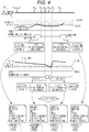
- FIG. 4 the tractor travels along a predetermined target travel route.
- a straight line in Fig. 4 illustrates the target travel route along which the tractor should travel.
- an actual travel route includes many straight travel routes and curved travel routes (180° turn and 90° turn) joining the adjacent straight travel routes.
- Reference signs Pn (n: a suffix) in Fig. 4 represent travel points identifying own positions on the target travel route. The travel points are each added with a map coordinate position (x, y).
- An engine water temperature representing state A corresponds to a detected signal sent from a water temperature sensor for detecting an engine water temperature.
- the detected signal sent from the water temperature sensor is compared with a first value (first condition) and a second value (second condition), which are water temperature thresholds set beforehand as conditions for determining abnormality.
- the second value is set higher than the first value.
- a residual fuel quantity representing state B corresponds to a detected signal sent from the residual fuel quantity sensor provided in the fuel tank 23.
- the detected signal on a residual fuel quantity is compared with a first value and a second value, which are thresholds for residual fuel quantity set beforehand as conditions for determining abnormality.
- the second value is set lower than the first value (a value close to a minimum fuel quantity).
- the work vehicle When the work vehicle is automatically travelled and controlled, the work vehicle is automatically travelled near an agricultural truck loaded with a reserve fuel tank and parked on a ridge. When fuel is supplied, the insufficient fuel warning and the insufficient fuel caution are cancelled at an own position of P31.
- abnormality information is generated by the abnormality information generation unit 63.
- the abnormality information includes, as attribute data, a type of a state determined as an abnormality, an executed notification operation, a detected signal value, and an own position at which the abnormality has occurred.
- a recovery process e.g., fuel supply, engine speed control
- a content of the recovery process is added to the abnormality information.
- the generated abnormality information is recorded by the abnormality information recording unit 65 in a format created such that the abnormality information follows a travel locus calculated based on own positions of the work vehicle calculated sequentially.
- a work vehicle like a tractor requires various entry operations even during travelling.
- a supervisor supervising the work vehicle being travelled automatically is also required to make various entry operations on the monitoring communication terminal 110 held by himself/herself.
- An erroneous operation prevention technique adopted in the touch panel 9 of this work vehicle will now be described herein with reference to Figs. 5, 6, and 7 .
- Fig. 5 shows an example of a touch surface 90 of the touch panel 9, where a plurality of (two in Fig. 5 ) valid operation areas 91 are disposed separately each other.
- An area on the touch surface 90 excluding the valid operation areas 91 is an invalid operation area 92 where a touch operation becomes invalid.
- the valid operation areas 91 include a first operation button 911 and a second operation button 912 disposed separately each other.
- a liquid crystal panel that cooperates with the touch panel 9 visibly displays the first operation button 911 and the second operation button 912.
- a condition satisfying a simultaneous touch of the first operation button 911 and the second operation button 912 is a simultaneous touch where a time difference is within approximately one second.
- a touch operation made before notified with a display or another method urging an entry operation is determined to be invalid. This configuration can reduce erroneous operations that could occur when the touch surface 90 is accidentally touched.
- the valid operation areas 91 configured by a plurality of dots defining a particular figure or a particular line are disposed on the touch surface 90 of the touch panel 9.
- An area on the touch surface 90 excluding the valid operation areas 91 is an invalid operation area 92 where a touch operation becomes invalid.
- the valid operation areas 91 configured by nine dots defines a circle.
- the valid operation areas 91 configured by eight dots define a check pattern.
- the liquid crystal panel that cooperates with the touch panel 9 visibly displays the particular figure (the circle in Fig. 6 ) or the particular diagram (the check pattern in Fig. 7 ) defined by the valid operation areas 91.
- An entry operation by a user is tracing of the circle or the check pattern in a single stroke made after notified with a display or another method urging the entry operation.
- a tracing operation may start at any position at that time, but continuity of an order of dots being traced becomes a condition for determining whether the tracing operation is valid or invalid.
- a total tracing time is also limited.
- a tracing operation made before notified with a display or another method urging an operation input is also determined to be invalid.
- a traced locus is visibly shown on the liquid crystal panel.
- the work vehicle in the above described exemplary embodiment has the automatic steering function of unmanned travel or no-driver travel with automatic steering and the manual steering function of manned travel with manual steering to select either the automatic travel (automatic steering) mode or the manual travel (manual steering) mode.
- the present invention is also applicable to a work vehicle having the manual steering function only or a work vehicle having the automatic steering function only.
- the present invention is also applicable to any work vehicles used in a work vehicle cooperation system where a plurality of work vehicles are loaded in a work field, and some of the plurality of work vehicles are operated in the manual travel (manual steering) mode, while the remaining work vehicles are operated in the automatic travel (automatic steering) mode.
- the first condition and the second condition that is more rigorous than first condition are applied to a single detected signal to determine either an early abnormality or an actual abnormality.
- a method for determining either an early abnormality or an actual abnormality based on a combination of different detected signals may be adopted.
- each function unit in the functional block diagram shown in Fig. 3 is separated for description purposes. In an actual case, each function unit can be integrated with other function units, or divided into a plurality of sub-function units.
- at least a part of the abnormality processing module 60 may be configured in a mobile phone or a tablet computer that can exchange data with the controlling unit 5 of the work vehicle.
- a tractor equipped with a rotary tilling machine as the work device 30.
- various work vehicles may be adopted as exemplary embodiments, such as agricultural vehicles including rice transplanters, fertilizer distributors, combines, and construction vehicles equipped with a dozer or a roller as the work device 30.
- the technology described above is applicable to all work vehicles that have an own position function and a travelling work state detection function, and that are used for performing a travelling work in a work field.
Landscapes
- Life Sciences & Earth Sciences (AREA)
- Engineering & Computer Science (AREA)
- General Physics & Mathematics (AREA)
- Physics & Mathematics (AREA)
- Environmental Sciences (AREA)
- Mechanical Engineering (AREA)
- Soil Sciences (AREA)
- General Engineering & Computer Science (AREA)
- Structural Engineering (AREA)
- Civil Engineering (AREA)
- Mining & Mineral Resources (AREA)
- Aviation & Aerospace Engineering (AREA)
- Radar, Positioning & Navigation (AREA)
- Remote Sensing (AREA)
- Automation & Control Theory (AREA)
- Guiding Agricultural Machines (AREA)
- Traffic Control Systems (AREA)
- Lifting Devices For Agricultural Implements (AREA)
- Alarm Systems (AREA)
- Control Of Position, Course, Altitude, Or Attitude Of Moving Bodies (AREA)
- Management, Administration, Business Operations System, And Electronic Commerce (AREA)
Description
- The present disclosure relates to a work vehicle having a function of determining an abnormality, based on signals sent from a group of sensors detecting states of a vehicle body and a work device.
- Document
JP 10-155327 A - Document
JP 2000-201104 A - A riding control machine according to
JP 2005-215742 A - According to
JP 2011-220104 A - The
document EP 1 441 077 A1 relates to a device for managing work machines such as construction machines. When driver identification data for identifying a driver A is inputted at the operating start time of a work machine, the inputted driver identification data, the operating time of the construction machine, and the time and date at which the driver identification data was inputted are transmitted from the work machine to a terminal device. As a result, the amount of time the construction machine was operated by the driver A is displayed on the terminal, and the work machine can be managed on the basis of this display content. Additionally service person identification data and attachment data can be entered and transmitted to the terminal device. - In the document
US 2014/236432 A1 , a method of monitoring a fluid system of a mining machine is disclosed, the method including sensing a pressure level of a fluid in the fluid system of the mining machine to generate pressure level data; analyzing the pressure level data to detect pressure level deviations; determining at least one selected from the group of when a frequency of the pressure level deviations exceeds a predetermined frequency, and when the fluid pressure level fails to reach a threshold within a predetermined reaction time period; and outputting an alert in response to the determination - In view of the above described circumstances, a technique has been demanded, which executes a more appropriate notification when any abnormality is detected in a work vehicle.
- A work vehicle according to
claim 1 is provided. - According to an aspect, a work vehicle comprises an own position calculation unit that calculates, based on positioning data, an own position which is a position of the work vehicle, a group of travelling work state detection sensors that outputs detected signals indicating a travelling work state, an early abnormality determination unit that determines, as an early abnormality, an abnormality at an early stage, which causes trouble in travelling work, based on the detected signals and a first condition, an actual abnormality determination unit that determines, as an actual abnormality, the abnormality at an actual stage, based on the detected signals and a second condition which is more rigorous than the first condition, a first notification unit that externally provides a notification of the early abnormality, based on a result of determination of the early abnormality, a second notification unit that externally provides a notification of the actual abnormality, based on a result of determination of the actual abnormality, and an abnormality information generation unit that generates abnormality information which is a combination of one of or both the determined early abnormality and the determined actual abnormality with an own position at which the abnormality has occurred. The term "travelling work" used herein includes work while travelling, a travelling operation itself, work itself, a state where at least one of the work while travelling, the travelling operation itself, and the work itself is performed, and a state where such travelling work is temporarily stopped.
- According to this configuration, an abnormality occurred in a work vehicle during travelling work may be determined and classified into an early abnormality which is an abnormality at an early stage, or an actual abnormality which is the abnormality at an actual stage and is further worsened from the early stage, and the early abnormality and the actual abnormality are externally notified. Therefore, a supervisor supervising the work vehicle externally receives notification of the early abnormality as a caution on the abnormality, for example, or the actual abnormality, a degree of which is further worsened from a degree of the early abnormality, as a warning on the abnormality, for example. One of or both the early abnormality and the actual abnormality is or are combined as abnormality information with the own position calculated when the abnormality has occurred. Even though the supervisor of the work vehicle is present at a location from which the work vehicle cannot be seen or a position of the work vehicle cannot be identified, the supervisor is able to therefore know a location at where an abnormality has occurred, as well as is able to take a more appropriate action against the occurred abnormality.
- By investigating an abnormality occurred in a work vehicle during travelling, while taking into account a travel route along which the work vehicle has actually travelled, a cause of the abnormality and its countermeasure can be examined. To this end, generated abnormality information should be connected to travelling operations and recorded, and the record should be read later. Therefore, the work vehicle includes an abnormality information recording unit that records the abnormality information in line with a travel locus.
- For an automatic travelling work vehicle that travels automatically with an automatic steering feature with which no driver is required, a supervisor positioned away from the automatic travelling work vehicle or a driver operating another manned work vehicle is required to check a state of a travelling work, in particular, check if any abnormality occurs. Notifications of an early abnormality and an actual abnormality externally as described above are therefore particularly advantageous for such an automatic travelling work vehicle. To this end, according to another advantageous exemplary embodiment of the present invention, the work vehicle includes an automatic travel control unit that generates, based on a difference between a predetermined target travel route and the own position, an automatic steering instruction for causing the work vehicle to travel along the target travel route, and notification information regarding the early abnormality and the actual abnormality is sent to a communication terminal held by a supervisor supervising an automatic travelling operation. This configuration allows the supervisor positioned away from the automatic travelling work vehicle or a driver operating another manned work vehicle to know promptly an abnormality occurred in the automatic travelling work vehicle, through the communication terminal. When the automatic travelling work vehicle provides notification of an abnormality through a lamp or a speaker, the supervisor is also able to know an abnormality occurred in the work vehicle even if the communication terminal is not held by the supervisor.
- If an actual abnormality occurs in a work vehicle, travelling work should be aborted, and the abnormality should be resolved, because the actual abnormality may cause serious trouble in the travelling work. In particular, for a work vehicle automatically travelling without a driver, any action should be taken automatically against an abnormality. To this end, according to still another advantageous exemplary embodiment of the present invention, the work vehicle includes an abnormality recovery processing unit that automatically executes an abnormality recovery process for resolving the abnormality, based on a result of determination of the early abnormality or the actual abnormality. This abnormality recovery processing function may also be executed while the work vehicle is operated manually by a driver. The abnormality recovery process includes, for example, a program for allowing the work vehicle to travel in a shortest distance toward a location at where fuel can be supplied if an abnormality relates to running short of fuel, a program for stopping the work vehicle and driving an engine at an appropriate engine speed if an abnormality relates to overheating, and a program for stopping the work vehicle and executing a filter regeneration process if an abnormality relates to excessive accumulation of particulate matter in a diesel particulate filter (DPF).
- If a determined abnormality may cause serious trouble in a travelling work, a process for immediately stopping the vehicle body, the engine, and the work device, stopping the vehicle body and the work device, or stopping the vehicle body only is required before executing a recovery process. In still another advantageous exemplary embodiment of the present invention, therefore, the abnormality recovery process includes a partial or complete stoppage of the automatic travelling operation.
- For a work vehicle for performing an agricultural operation in a field, it is preferable that fuel should be supplied and a troubled engine should be repaired, as an abnormality recovery process, around the field such as on a ridge, instead of within the field. To this end, according to still another advantageous exemplary embodiment of the present invention, when the travelling operation is performed in a field separated by ridges as boundaries and the abnormality recovery process is performed near one of the ridges, the abnormality recovery process includes an automatic travelling operation through which the work vehicle automatically approaches the one of the ridges.
- Abnormalities that may cause serious trouble in a travelling work vary, not a single one, thus abnormality recovery processes vary. Support contents for a supervisor and other persons, required when performing an abnormality recovery process at that time, also vary depending on skills of the supervisor and other persons. The abnormality recovery processing unit may therefore be advantageous if a content of an abnormality recovery process is settable beforehand in accordance with a type of an abnormality.
- The work vehicle further comprises an abnormality information recording unit that records the abnormality information in line with a travel locus.
- The work vehicle may further comprise an automatic travel control unit that generates, based on a difference between a predetermined target travel route and the own position, an automatic steering instruction for causing the work vehicle to travel along the target travel route, wherein notification information regarding the early abnormality and the actual abnormality may be sent to a communication terminal held by a supervisor supervising an automatic travelling operation.
- The work vehicle may further comprise an abnormality recovery processing unit that automatically executes an abnormality recovery process for resolving the abnormality, based on a result of determination of the early abnormality or the actual abnormality.
- The abnormality recovery process may include a partial or complete stoppage of the automatic travelling operation.
- When the travelling operation is performed in a field separated by ridges as boundaries and the abnormality recovery process may be performed near one of the ridges, the abnormality recovery process may include an automatic travelling operation through which the work vehicle automatically approaches the one of the ridges.
- A content of the abnormality recovery process may be settable beforehand in accordance with a type of the abnormality.
- Following, further embodiments are described in detail by referring to figures. In the figures, show:
- Fig. 1
- a side view of a tractor which is an exemplary embodiment of a work vehicle;
- Fig. 2
- an explanatory view illustrating a configuration of an engine system of the tractor;
- Fig. 3
- a functional block diagram illustrating a control system of the tractor;
- Fig. 4
- an explanatory view illustrating an example of an abnormality occurrence management control in a travelling work performed in a work field;
- Fig. 5
- an explanatory view illustrating a technique of preventing as much as possible erroneous touch operations on a touch panel;
- Fig. 6
- an explanatory view illustrating a technique of preventing as much as possible erroneous trace operations on the touch panel; and
- Fig. 7
- another explanatory view illustrating a technique of preventing as much as possible erroneous trace operations on the touch panel.
- Next, with reference to the drawings, exemplary embodiments of a work vehicle will now be described herein. In this exemplary embodiments, as shown in
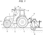
Fig. 1 , the work vehicle is a tractor that travels and works in a field (work field) separated by ridges as boundaries. This tractor is provided with anoperation unit 20 partitioned by acabin 21 at a center of avehicle body 1 supported byfront wheels 11 andrear wheels 12. At a rear of thevehicle body 1, awork device 30 that is a rotary tilling machine is mounted via ahydraulic lifting mechanism 31. Thefront wheels 11 function as steering control wheels through which the tractor changes a travel direction when a steering angle of the steering control wheels is changed. The steering angle of thefront wheels 11 is changed by an operation of asteering mechanism 13. Thesteering mechanism 13 includes asteering motor 14 for automatic steering. For manual travelling, thefront wheels 11 are steered by operating asteering wheel 22 disposed on theoperation unit 20. Anengine 4 is mounted in a front area of thevehicle body 1, and engine power is transmitted to thefront wheels 11 and therear wheels 12 via atransmission 15 including a multiple-transmission mechanism and a clutch mechanism. Afuel tank 23 for supplying fuel to theengine 4 is disposed under thecabin 21. Thefuel tank 23 is attached with a residual fuel quantity sensor that detects a residual fuel quantity. - In the
cabin 21 of the tractor, asatellite positioning module 80 configured as a GNSS module is provided. As a component of thesatellite positioning module 80, a satellite antenna for receiving GPS signals and GNSS signals is attached at a ceiling area of thecabin 21. Thesatellite positioning module 80 may include an inertial navigation module incorporated with a gyro acceleration sensor and a magnetic director sensor for complementing satellite navigation. The inertial navigation module may also be provided in a different location from that of thesatellite positioning module 80. Various sensors that output detected signals indicating a travelling work state of this work vehicle are further disposed around thevehicle body 1 and thework device 30. - As shown in
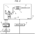
Fig. 2 , theengine 4 that is a diesel engine constitutes an engine unit EU attached with, for example, anexhaust pipe unit 40 for discharging exhaust gas from thisengine 4, anexhaust gas purifier 41, a selective catalytic reduction (SCR) 42, and aseparator 43. In this exemplary embodiment, theexhaust gas purifier 41 includes a filter for collecting particulate matter contained in exhaust gas, i.e., a diesel particulate filter (DPF). Exhaust gas from theengine 4 flows into a front end of theexhaust gas purifier 41, and exhaust gas treated by theexhaust gas purifier 41 flows from a rear end of theexhaust gas purifier 41. The exhaust gas flowed from theexhaust gas purifier 41 passes through theSCR 42. At that time, theSCR 42 sprays aqueous urea toward the exhaust gas to purify nitrogen oxide in the exhaust gas. - Since particulate matter accumulates in the DPF as a travel time increases, a filter regeneration process is required to be performed to burn and remove the particulate matter when an accumulation amount (DPF accumulation amount) reaches a predetermined value. Although aqueous urea to be used in the
SCR 42 is stored in an aqueous urea tank, the aqueous urea is required to be replenished when its residual quantity lowers below a predetermined value. To this end, a sensor for detecting the DPF accumulation amount and a sensor for detecting a residual aqueous urea quantity are disposed. The engine unit EU is further disposed with a sensor for detecting a water level in theseparator 43 and a sensor for detecting an engine water temperature. InFig. 2 , these sensors around the engine are collectively indicated as a group of enginesystem detection sensors 83. -
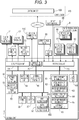
Fig. 3 illustrates a control system configured in this tractor. This control system has a function of controlling abnormalities on the tractor (work vehicle) that could occur during travelling works in fields (work fields). The controllingunit 5 is a core element of this control system, and includes anoutput processing unit 7A and aninput processing unit 7B, which respectively function as input and output interfaces, and a communication processing unit 7C. Theoutput processing unit 7A is connected with, for example, anengine controlling unit 70, a group ofvehicle travel devices 71, a group ofwork devices 72, and anotification device 73. Theengine controlling unit 70 controls various operation devices included in the engine unit EU based on control instructions sent through theoutput processing unit 7A, or based on an individual control program. The group ofvehicle travel devices 71 includes thesteering motor 14 and devices to be controlled for allowing the vehicle to travel normally, such as operation devices incorporated in thetransmission 15. The group ofwork devices 72 includes, for example, a drive mechanism for thework device 30, and alifting mechanism 31 that raises and lowers thework device 30. Thenotification device 73 includes a display, lamps, and a speaker, and is used to warn the driver and a supervisor of an abnormality occurred in a travelling work. Signals are transmitted between thenotification device 73 and theoutput processing unit 7A in a wired or wireless manner. - The communication processing unit 7C exchanges data with an external computer in conformity to a wireless communication standard and a wired communication standard.
Fig. 3 shows acontrol computer 100 constituted as an external computer in a control center KS in a remote location, and amonitoring communication terminal 110 held by a supervisor supervising the work vehicle being unmanned operated. - The
input processing unit 7B is coupled to, for example, a group of travelling workstate detection sensors 8, thesatellite positioning module 80, an automatic/manual switch 85, and atouch panel 9. The group of travelling workstate detection sensors 8 is a group of sensors for detecting various states of this tractor performing a travelling work (including switches and buttons). The group of travelling workstate detection sensors 8 includes a group of travelsystem detection sensors 81, a group of worksystem detection sensors 82, and the group of enginesystem detection sensors 83. The group of travelsystem detection sensors 81 includes sensors for detecting vehicle body states and travel states including a vehicle speed, a transmission state, an inclination of the vehicle body, and a residual fuel quantity. The group of worksystem detection sensors 82 includes, for example, sensors for detecting a ground clearance and an inclination of thework device 30, and sensors for detecting workloads and the like. The group of enginesystem detection sensors 83 includes, for example, sensors for detecting an engine speed and an engine water temperature, a sensor for assuming or detecting a DPF accumulation amount, and sensors for detecting a residual SCR quantity (residual aqueous urea quantity) and a water level of the separator. - The automatic/
manual switch 85 is a switch that selects either an automatic steering mode for travelling with automatic steering or a manual steering mode for travelling with manual steering. For example, by operating the automatic/manual switch 85 while travelling, a mode of the work vehicle can be switched from the automatic travel (automatic steering) mode to the manual travel (manual steering) mode, and vice versa. - The
touch panel 9 cooperates with a liquid crystal display included in thenotification device 73 to accept an entry of a user operation. - The controlling
unit 5 is configured to include anabnormality processing module 60 that is a core function unit for controlling abnormalities that could occur in the work vehicle during travelling work, in particular an unmanned travelling work. The controllingunit 5 also includes atravel control unit 50, awork control unit 53, an ownposition calculation unit 54, an unmanned/mannedoperation detection unit 55, a workfield control unit 56, aroute generation unit 57, and anotification unit 58. Although the controllingunit 5 is illustrated as a single unit inFig. 3 in order to provide a simple description, the controllingunit 5 is normally divided into a plurality of subunits, and the subunits are connected in such a manner that data can be transmitted each other through an on-vehicle LAN or other communication lines. - Since the automatic travel (automatic steering) mode and the manual travel (manual steering) mode are both configured to be available in this tractor for travelling, the
travel control unit 50 for controlling the group ofvehicle travel devices 71 includes a manualtravel control unit 51 and an automatictravel control unit 52. In accordance with operations of the driver, the manualtravel control unit 51 controls the group ofvehicle travel devices 71. Based on a deviation between an own position and a target travel route, the automatictravel control unit 52 generates and outputs an automatic steering instruction to thesteering motor 14 via theoutput processing unit 7A. To control movement of thework device 30, thework control unit 53 provides control signals to the group ofwork devices 72. Based on the positioning data sent from thesatellite positioning module 80, the ownposition calculation unit 54 calculates an own position. The unmanned/mannedoperation detection unit 55 determines whether the work vehicle is unmanned operated (no-driver operated) or manned operated based on a state signal sent from the automatic/manual switch 85. A determination as to whether the driver is seated on a driver's seat can also be made based on a state signal sent from a seat switch included in the group of travelsystem detection sensors 81. - The
notification unit 58 generates notification information (including a display signal, a voice signal, a lamp drive signal, and a buzzer drive signal) for externally notifying information regarding an early abnormality or an actual abnormality to the driver or the supervisor through thenotification device 73 such as the display, the speaker, and the lamps. Thisnotification unit 58 includes afirst notification unit 581 and asecond notification unit 582 each having different functions. As will be described in detail later, when theabnormality processing module 60 determines an early abnormality in a particular travelling work state, thefirst notification unit 581 notifies the early abnormality outside the work vehicle. When theabnormality processing module 60 determines an actual abnormality that is more serious than the early abnormality, thesecond notification unit 582 notifies the actual abnormality outside the work vehicle. A message or an illustration may be used when a display signal is used as notification information. Thus, a notification of an early abnormality and a notification of an actual abnormality can be expressly distinguished. When a lamp drive signal or a buzzer drive signal is used as notification information, a notification of an early abnormality and a notification of an actual abnormality can be distinguished with a drive pattern of the lamps and the buzzer, such as different intermittent drive intervals, for example. When a lamp drive signal is used as notification information, a format may be adopted, where a yellow lamp is driven to notify an early abnormality, whereas a red lamp is driven to notify an actual abnormality. - The
notification unit 58 can further transmit the above described notification information to themonitoring communication terminal 110 or an ordinary mobile phone through the communication processing unit 7C. Even when the tractor is automatically travelled and is not watched directly, the supervisor can promptly be notified of an abnormality occurred in the tractor being automatic travelled. - The work
field control unit 56 controls field information (work field information) that is information regarding the field in which the work vehicle works and travels. The field information includes data such as a map position, shape, and size of a field, as well as plant varieties. The field information can be downloaded from, for example, thecontrol computer 100 disposed in the control center KS in the remote location or a farmer's home. - Based on the field information, the
route generation unit 57 reads external shape data of the field, and generates a target travel route that fits to this field. This target travel route may be automatically generated based on basic initial parameters such as a start point and an end point entered by an operator, or may be automatically generated based on a simple route pattern entered by the operator. A configuration may be adopted, through which a target travel route itself is downloaded from thecontrol computer 100. In any case, the target travel route obtained from theroute generation unit 57 is developed in a memory, and used by the work vehicle to travel along the target travel route regardless of whether the work vehicle is operated in either the automatic travel (automatic steering) mode or the manual travel (manual steering) mode. - The
abnormality processing module 60 determines an abnormality that could cause trouble in travelling work, based on detected signals indicating a travelling work state, which are sent from the group of travelling workstate detection sensors 8, and provides a result of determination of the abnormality to thenotification unit 58. Theabnormality processing module 60 according to this exemplary embodiment includes an earlyabnormality determination unit 61, an actualabnormality determination unit 62, an abnormalityinformation generation unit 63, an abnormalityrecovery processing unit 64, and an abnormalityinformation recording unit 65. - The early
abnormality determination unit 61 determines, as an early abnormality, an abnormality at an early stage, which could cause trouble in travelling work, based on detected signals sent from the group of travelling workstate detection sensors 8 and a first condition. When the early abnormality is determined, the earlyabnormality determination unit 61 gives information about an event causing the early abnormality in the travelling work, for example, a rise in an engine water temperature, and a reduction in a residual fuel quantity, to thefirst notification unit 581. The actualabnormality determination unit 62 determines, as an actual abnormality, the abnormality at an actual stage, which is more serious than the early abnormality, based on detected signals sent from the group of travelling workstate detection sensors 8 and a second condition that is more rigorous than the above described first condition. When the actual abnormality is determined, the actualabnormality determination unit 62 gives information about an event causing the actual abnormality in the travelling work to thesecond notification unit 582. The earlyabnormality determination unit 61 and the actualabnormality determination unit 62 determine various abnormalities in travelling work, and signals to be detected and used for determination vary depending on a type of abnormality. The first condition used for determining an early abnormality and the second condition used for determining an actual abnormality also vary depending on a type of a detected signal. - When the early
abnormality determination unit 61 determines an early abnormality or when the actualabnormality determination unit 62 determines an actual abnormality, the abnormalityinformation generation unit 63 generates, in a predetermined format, abnormality information combined with a content of the abnormality and a vehicle position at which the abnormality has occurred. The abnormalityinformation recording unit 65 records the abnormality information generated by the abnormalityinformation generation unit 63 in line with a travel locus recorded in a format created so as to conform to a travel locus calculated based on own positions of the work vehicle sequentially calculated by the ownposition calculation unit 54. The recorded abnormality information is sent to thecontrol computer 100 in the control center KS with a real-time process or a batch process for use in future maintenance and inspection control of the tractor. - An abnormality control first may notify an abnormality only when an early abnormality is determined, and, after that, when the abnormality worsens to an extent that the abnormality is determined as an actual abnormality, aborts a travelling work itself. A specific example of such an abnormality control will now be described herein.
- (1) Engine water temperature: Since an engine water temperature could lead to a risk of overheat, first an early abnormality is notified when the engine water temperature reaches a predetermined temperature. After the engine water temperature further rises, and an actual abnormality is determined, the actual abnormality is notified, and a process for preventing the engine from being heated excessively is executed, such as the tractor is stopped and an engine speed is lowered to an appropriate speed.
- (2) DPF accumulation amount: An early abnormality is notified when a DPF accumulation amount reaches a predetermined, excessive accumulation amount, and a filter regeneration process through which particulate matter accumulated in the filter is burnt and removed is urged to be performed. If the filter regeneration process has not yet performed, but particulate matter accumulates excessively, thus an actual abnormality is determined, the actual abnormality is notified, the tractor is stopped, and the filter regeneration process is forcibly executed in order to avoid a risk of damage in the DPF, so that the DPF is not required to be replaced.
- (3) Residual fuel quantity: At a residual fuel quantity with which the tractor can still travel some distance, an early abnormality is notified, and supply of fuel is urged. If the tractor is kept travelled without supplied with fuel, and fuel is about to run short, an actual abnormality is determined and notified. When the tractor is automatically travelled, the tractor is forcibly stopped, or an automatic travelling operation is executed to cause the tractor to approach a ridge set as a fuel supply location.
- (4) Water level of separator: If an abnormality recovery process has not yet performed, thus a water level of separator rises, even after an early abnormality is notified, an actual abnormality is determined and notified, and the tractor is forcibly stopped.
- (5) Residual SCR quantity: Similar to the residual fuel quantity, if a reductant, i.e., aqueous urea has not yet replenished, thus aqueous urea reduces to a dangerous water level, even after an early abnormality is notified, an actual abnormality is notified, and the tractor is forcibly stopped, or an automatic travelling operation is executed to cause the tractor to approach a ridge set as an aqueous urea supply location.
- Based on an early abnormality determined by the early
abnormality determination unit 61 or an actual abnormality determined by the actualabnormality determination unit 62, the abnormalityrecovery processing unit 64 automatically executes any of the above described abnormality recovery processes for resolving the abnormality. Since abnormalities include abnormalities relating to various failure events, such as travel system abnormalities, work system abnormalities, and engine system abnormalities, the abnormalityrecovery processing unit 64 stores procedures for abnormality recovery processes associated with early abnormalities and actual abnormalities regarding the aforementioned abnormalities. Abnormality recovery processes often vary depending on whether the tractor is in automatic travelling (unmanned travelling) or manual travelling (manned travelling). In automatic travelling, if the supervisor fails to find a notification on an abnormality, the abnormality becomes serious. To avoid such an event, an abnormality recovery process is provided to partially or completely abort the automatic travelling if a particular abnormality has been determined. For an insufficient fuel abnormality and an insufficient SCR (insufficient aqueous urea) abnormality, another abnormality recovery process is provided to cause the tractor to automatically travel, approach a ridge, and wait for supply. If a particular abnormality occurs, two options are available: to wait until a supervisor resolves the abnormality; and to perform an abnormality recovery process automatically by the work vehicle itself. However, such a selection can often differ depending on skills of the supervisor. Therefore, a content of an abnormality recovery process is set beforehand in accordance with a type of an abnormality. - A basic flow of abnormality control performed by the
abnormality processing module 60 and thenotification unit 58 is as described below. - (a) In an automatic travelling work state, an abnormality that could damage the tractor (work vehicle) or an abnormality that could lower work efficiency is monitored by comparing the abnormality with conditions set per a type of an abnormality.
- (b) When an early abnormality is determined based on a first condition, a content of the early abnormality is externally notified to the supervisor by means of a visual or audio device, and is sent to other work vehicles and the
monitoring communication terminal 110 via a wireless communication or the like. - (c) When an actual abnormality is determined based on a second condition that is more rigorous than the first condition, since the tractor (work vehicle) could be damaged if the travelling work continues, the content of the actual abnormality is externally notified to the supervisor by means of a visual or audio device, and the automatic travelling work is aborted.
- (d) An own position at which the early abnormality has occurred and an own position at which the actual abnormality has occurred are recorded together with contents of the abnormalities.
- (e) An own position at which an early abnormality has occurred and an abnormality recovery process to be performed when an actual abnormality has occurred are set separately per a type of an abnormality.
- Next, flows of abnormality controls with regard to two states (state A: engine water temperature, state B: residual fuel quantity) of the tractor (work vehicle) in travelling work will now be described herein with reference to
Fig. 4 . In examples shown inFig. 4 , the tractor travels along a predetermined target travel route. A straight line inFig. 4 illustrates the target travel route along which the tractor should travel. However, an actual travel route includes many straight travel routes and curved travel routes (180° turn and 90° turn) joining the adjacent straight travel routes. Reference signs Pn (n: a suffix) inFig. 4 represent travel points identifying own positions on the target travel route. The travel points are each added with a map coordinate position (x, y). - An engine water temperature representing state A, which is one of travelling work states, corresponds to a detected signal sent from a water temperature sensor for detecting an engine water temperature. The detected signal sent from the water temperature sensor is compared with a first value (first condition) and a second value (second condition), which are water temperature thresholds set beforehand as conditions for determining abnormality. The second value is set higher than the first value. When an abnormality where a detected signal exceeds the first value (a type of an early abnormality) occurs, notification is provided to urge execution of a measure for reducing an engine load. When an abnormality where a detected signal exceeds the second value (a type of an actual abnormality) further occurs, the tractor is stopped, and notification is provided to urge execution of a measure for driving the engine at an engine speed around an idling speed provided that a radiator is normal. These actions are executed automatically in an automatic travelling operation where no passenger is attended. In the examples shown in
Fig. 4 , since a detected signal sent from the water temperature sensor exceeds the first value at an own position of P18, an overheat caution is notified as a notification operation of state A. When a user receives this notification, he/she lowers an operation speed to reduce an engine load of the tractor. Next, since a detected signal sent from the water temperature sensor lowers below the first value at an own position of P23, the notification operation of state A is cancelled. In the examples shown inFig. 4 , since a detected signal sent from the water temperature sensor exceeds the first value again at an own position of P37, an overheat caution is notified as a notification operation of state A. - A residual fuel quantity representing state B, which is another one of travelling work states, corresponds to a detected signal sent from the residual fuel quantity sensor provided in the
fuel tank 23. The detected signal on a residual fuel quantity is compared with a first value and a second value, which are thresholds for residual fuel quantity set beforehand as conditions for determining abnormality. The second value is set lower than the first value (a value close to a minimum fuel quantity). When an abnormality where a detected signal lowers below the first value (a type of an early abnormality) occurs, an insufficient fuel caution is notified. When an abnormality where a detected signal lowers below the second value (a type of an actual abnormality) further occurs, an insufficient fuel warning is notified to urge immediate supply of fuel. - In the examples shown in
Fig. 4 , since a detected signal sent from the residual fuel quantity sensor lowers below the first value at an own position of P26, an insufficient fuel caution is notified as a notification operation of state B. When the supervisor of this travelling work receives this caution, he/she investigates a time and a place for supplying fuel to the tractor. Since the tractor further consumes fuel, and a detected signal sent from the residual fuel quantity sensor lowers below the second value at an own position of P29, an insufficient fuel warning is notified. Accordingly, the tractor once stops the travelling work. The tractor is then supplied with fuel, or moved to a place appropriate for supplying fuel. When the work vehicle is automatically travelled and controlled, the work vehicle is automatically travelled near an agricultural truck loaded with a reserve fuel tank and parked on a ridge. When fuel is supplied, the insufficient fuel warning and the insufficient fuel caution are cancelled at an own position of P31. - As described above, when detected signals sent from the group of travelling work
state detection sensors 8 are evaluated with predetermined conditions, and an early abnormality or an actual abnormality is determined, abnormality information is generated by the abnormalityinformation generation unit 63. The abnormality information includes, as attribute data, a type of a state determined as an abnormality, an executed notification operation, a detected signal value, and an own position at which the abnormality has occurred. When a recovery process (e.g., fuel supply, engine speed control) is executed to resolve the abnormality at that time, a content of the recovery process is added to the abnormality information. The generated abnormality information is recorded by the abnormalityinformation recording unit 65 in a format created such that the abnormality information follows a travel locus calculated based on own positions of the work vehicle calculated sequentially. - A work vehicle like a tractor requires various entry operations even during travelling. A supervisor supervising the work vehicle being travelled automatically is also required to make various entry operations on the
monitoring communication terminal 110 held by himself/herself. When making these entry operations on thetouch panel 9 having a relatively smaller screen size, care should be taken to avoid erroneous operations. An erroneous operation prevention technique adopted in thetouch panel 9 of this work vehicle will now be described herein with reference toFigs. 5, 6, and 7 . -
Fig. 5 shows an example of atouch surface 90 of thetouch panel 9, where a plurality of (two inFig. 5 )valid operation areas 91 are disposed separately each other. An area on thetouch surface 90 excluding thevalid operation areas 91 is aninvalid operation area 92 where a touch operation becomes invalid. In this example, thevalid operation areas 91 include a first operation button 911 and a second operation button 912 disposed separately each other. A liquid crystal panel that cooperates with thetouch panel 9 visibly displays the first operation button 911 and the second operation button 912.
When the first operation button 911 and the second operation button 912 are kept touched simultaneously for a predetermined period, an operation entry command is generated and assigned to thevalid operation areas 91, and a process based on this operation entry command is executed. A condition satisfying a simultaneous touch of the first operation button 911 and the second operation button 912 is a simultaneous touch where a time difference is within approximately one second. A touch operation made before notified with a display or another method urging an entry operation is determined to be invalid. This configuration can reduce erroneous operations that could occur when thetouch surface 90 is accidentally touched. - In
Figs. 6 and 7 , thevalid operation areas 91 configured by a plurality of dots defining a particular figure or a particular line are disposed on thetouch surface 90 of thetouch panel 9. An area on thetouch surface 90 excluding thevalid operation areas 91 is aninvalid operation area 92 where a touch operation becomes invalid. InFig. 6 , thevalid operation areas 91 configured by nine dots defines a circle. InFig. 7 , thevalid operation areas 91 configured by eight dots define a check pattern. The liquid crystal panel that cooperates with thetouch panel 9 visibly displays the particular figure (the circle inFig. 6 ) or the particular diagram (the check pattern inFig. 7 ) defined by thevalid operation areas 91. An entry operation by a user is tracing of the circle or the check pattern in a single stroke made after notified with a display or another method urging the entry operation. A tracing operation may start at any position at that time, but continuity of an order of dots being traced becomes a condition for determining whether the tracing operation is valid or invalid. A total tracing time is also limited. A tracing operation made before notified with a display or another method urging an operation input is also determined to be invalid. To facilitate an easy tracing operation, a traced locus is visibly shown on the liquid crystal panel. - The work vehicle in the above described exemplary embodiment has the automatic steering function of unmanned travel or no-driver travel with automatic steering and the manual steering function of manned travel with manual steering to select either the automatic travel (automatic steering) mode or the manual travel (manual steering) mode. However, the present invention is also applicable to a work vehicle having the manual steering function only or a work vehicle having the automatic steering function only. The present invention is also applicable to any work vehicles used in a work vehicle cooperation system where a plurality of work vehicles are loaded in a work field, and some of the plurality of work vehicles are operated in the manual travel (manual steering) mode, while the remaining work vehicles are operated in the automatic travel (automatic steering) mode.
- In the above described exemplary embodiment, the first condition and the second condition that is more rigorous than first condition are applied to a single detected signal to determine either an early abnormality or an actual abnormality. However, instead of the first condition and the second condition, a method for determining either an early abnormality or an actual abnormality based on a combination of different detected signals may be adopted.
- Each function unit in the functional block diagram shown in
Fig. 3 is separated for description purposes. In an actual case, each function unit can be integrated with other function units, or divided into a plurality of sub-function units. In addition, at least a part of theabnormality processing module 60 may be configured in a mobile phone or a tablet computer that can exchange data with the controllingunit 5 of the work vehicle. - The above described exemplary embodiments have appointed, as the work vehicle, a tractor equipped with a rotary tilling machine as the
work device 30. However, in addition to such a tractor, various work vehicles may be adopted as exemplary embodiments, such as agricultural vehicles including rice transplanters, fertilizer distributors, combines, and construction vehicles equipped with a dozer or a roller as thework device 30. - The technology described above is applicable to all work vehicles that have an own position function and a travelling work state detection function, and that are used for performing a travelling work in a work field.
-
- 1
- vehicle body
- 23
- fuel tank
- 30
- work device
- 4
- engine
- 41
- DPF (exhaust gas purifier)
- 42
- SCR
- 43
- separator
- 5
- controlling unit
- 54
- own position calculation unit
- 58
- notification unit
- 581
- first notification unit
- 582
- second notification unit
- 60
- abnormality processing module
- 61
- early abnormality determination unit
- 62
- actual abnormality determination unit
- 63
- abnormality information generation unit
- 64
- abnormality recovery processing unit
- 65
- abnormality information recording unit
- 73
- notification device
- 8
- group of travelling work state detection sensors
- 80
- satellite positioning module
- 81
- group of travel system detection sensors
- 82
- group of work system detection sensors
- 83
- group of engine system detection sensors
Claims (6)
- A work vehicle comprising:- an own position calculation unit (54) that calculates, based on positioning data, an own position which is a position of the work vehicle;- a group of travelling work state detection sensors (8) that outputs detected signals indicating a travelling work state; characterised by- an early abnormality determination (61) unit that determines, as an early abnormality, an abnormality at an early stage, which causes trouble in travelling work, based on the detected signals and a first condition;- an actual abnormality determination unit (62) that determines, as an actual abnormality, the abnormality at an actual stage, based on the detected signals and a second condition which is more rigorous than the first condition;- a first notification unit (581) that externally provides a notification of the early abnormality, based on a result of determination of the early abnormality;- a second notification unit (582) that externally provides a notification of the actual abnormality, based on a result of determination of the actual abnormality; and- an abnormality information generation unit (63) that generates abnormality information which is a combination of one of or both the determined early abnormality and the determined actual abnormality with an own position calculated when the abnormality has occurred,- an abnormality information recording unit (65) that records the abnormality information in line with a travel locus.
- The work vehicle according to claim 1, further comprising an automatic travel control unit (52) that generates, based on a difference between a predetermined target travel route and the own position, an automatic steering instruction for causing the work vehicle to travel along the target travel route, wherein notification information regarding the early abnormality and the actual abnormality is sent to a communication terminal (110) held by a supervisor supervising an automatic travelling operation.
- The work vehicle according to claim 2, further comprising an abnormality recovery processing unit (63) that automatically executes an abnormality recovery process for resolving the abnormality, based on a result of determination of the early abnormality or the actual abnormality.
- The work vehicle according to claim 3, wherein the abnormality recovery process includes a partial or complete stoppage of the automatic travelling operation.
- The work vehicle according to claim 3 or 4, wherein when the travelling operation is performed in a field separated by ridges as boundaries and the abnormality recovery process is performed near one of the ridges, the abnormality recovery process includes an automatic travelling operation through which the work vehicle automatically approaches the one of the ridges.
- The work vehicle according to any one of claims 3 to 5, wherein a content of the abnormality recovery process is settable beforehand in accordance with a type of the abnormality.
Applications Claiming Priority (1)
| Application Number | Priority Date | Filing Date | Title |
|---|---|---|---|
| JP2016144563A JP6929026B2 (en) | 2016-07-22 | 2016-07-22 | Work platform |
Publications (2)
| Publication Number | Publication Date |
|---|---|
| EP3272950A1 EP3272950A1 (en) | 2018-01-24 |
| EP3272950B1 true EP3272950B1 (en) | 2019-07-17 |
Family
ID=57590307
Family Applications (1)
| Application Number | Title | Priority Date | Filing Date |
|---|---|---|---|
| EP16203450.8A Active EP3272950B1 (en) | 2016-07-22 | 2016-12-12 | Work vehicle with abnormality detection system |
Country Status (4)
| Country | Link |
|---|---|
| US (1) | US10109123B2 (en) |
| EP (1) | EP3272950B1 (en) |
| JP (1) | JP6929026B2 (en) |
| CN (1) | CN107640108B (en) |
Families Citing this family (20)
| Publication number | Priority date | Publication date | Assignee | Title |
|---|---|---|---|---|
| JP6059027B2 (en) * | 2013-01-21 | 2017-01-11 | 株式会社クボタ | Farm machine and farm work management program |
| JP6511148B2 (en) * | 2017-07-27 | 2019-05-15 | 株式会社小松製作所 | Control system, work machine, and control method |
| CN110293994A (en) * | 2018-03-21 | 2019-10-01 | 中车株洲电力机车研究所有限公司 | A kind of method and control system of the operation of control repair apparatus |
| JP2019176801A (en) * | 2018-03-30 | 2019-10-17 | 株式会社クボタ | Field work vehicle |
| JP7261468B2 (en) * | 2018-08-10 | 2023-04-20 | 和同産業株式会社 | Autonomous lawn mower |
| JP7034056B2 (en) * | 2018-12-21 | 2022-03-11 | 株式会社クボタ | Paddy field planting work machine and automatic running control system for paddy field planting work machine |
| JP7096531B2 (en) * | 2018-12-27 | 2022-07-06 | 井関農機株式会社 | Autonomous driving system for work vehicles |
| JP7075598B2 (en) * | 2019-02-27 | 2022-05-26 | 井関農機株式会社 | Work vehicle |
| JP7107270B2 (en) * | 2019-04-09 | 2022-07-27 | トヨタ自動車株式会社 | vehicle |
| CN110672482A (en) * | 2019-09-10 | 2020-01-10 | 烟台海德专用汽车有限公司 | Air dust intellectual detection system and dust fall operation dispatch system |
| JP7375690B2 (en) * | 2020-06-29 | 2023-11-08 | 井関農機株式会社 | Work vehicle control system |
| JP7428164B2 (en) * | 2021-06-09 | 2024-02-06 | トヨタ自動車株式会社 | tractor |
| JP7524136B2 (en) * | 2021-06-21 | 2024-07-29 | 株式会社クボタ | Machinery information collection system |
| EP4381511A4 (en) * | 2021-08-06 | 2025-06-18 | Blue River Technology Inc. | Detecting untraversable environment and preventing damage by a vehicle |
| AU2022275438B2 (en) * | 2021-12-28 | 2025-01-02 | Blue River Technology Inc. | Compensatory actions for automated farming machine failure |
| US12265383B2 (en) | 2021-12-28 | 2025-04-01 | Deere & Company | Compensatory actions for automated farming machine failure |
| US11926333B2 (en) * | 2021-12-28 | 2024-03-12 | Blue River Technology Inc. | Compensatory actions for automated farming machine failure |
| US20230334279A1 (en) * | 2022-04-13 | 2023-10-19 | Ford Global Technologies, Llc | Vehicle access card with an integrated display |
| DE102022110130A1 (en) * | 2022-04-27 | 2023-11-02 | Claas Selbstfahrende Erntemaschinen Gmbh | Method for monitoring operation of an autonomous agricultural machine |
| CN116090912B (en) * | 2023-04-12 | 2023-07-04 | 中通新能源汽车有限公司 | Sanitation operation state intelligent checking method, system and storage medium |
Citations (7)
| Publication number | Priority date | Publication date | Assignee | Title |
|---|---|---|---|---|
| EP1441077A1 (en) | 2003-01-24 | 2004-07-28 | Komatsu Ltd. | work machine management device |
| WO2010062329A1 (en) | 2008-10-28 | 2010-06-03 | The Gates Corporation | Diagnostic and response systems and methods for fluid power systems |
| DE102011086021A1 (en) | 2011-11-09 | 2013-05-16 | Deere & Company | Arrangement and method for automatic documentation of fieldwork situations |
| US20150310678A1 (en) | 2013-12-11 | 2015-10-29 | Komatsu Ltd. | Work machine, control system for work machine, and control method for work machine |
| WO2016056323A1 (en) | 2014-10-07 | 2016-04-14 | ヤンマー株式会社 | Remote server |
| EP3040936A1 (en) | 2013-08-28 | 2016-07-06 | Yanmar Co., Ltd. | Remote server |
| US10113423B2 (en) | 2013-02-18 | 2018-10-30 | Joy Global Surface Mining Inc | Systems and methods for monitoring a fluid system of a mining machine |
Family Cites Families (18)
| Publication number | Priority date | Publication date | Assignee | Title |
|---|---|---|---|---|
| JPH10155327A (en) | 1996-11-28 | 1998-06-16 | Yanmar Agricult Equip Co Ltd | Combine |
| JP2000201104A (en) | 1999-01-08 | 2000-07-18 | Hino Motors Ltd | Vehicle maintenance status notification device |
| JP2002042196A (en) * | 2000-07-31 | 2002-02-08 | Iseki & Co Ltd | Work vehicle management system |
| JP4126360B2 (en) * | 2003-09-09 | 2008-07-30 | 井関農機株式会社 | Paddy field machine |
| JP2005215742A (en) * | 2004-01-27 | 2005-08-11 | Yanmar Co Ltd | Agricultural work vehicle |
| JP4453764B2 (en) * | 2008-02-22 | 2010-04-21 | トヨタ自動車株式会社 | Vehicle diagnostic device, vehicle diagnostic system, and diagnostic method |
| JP5389858B2 (en) | 2011-05-12 | 2014-01-15 | 株式会社小松製作所 | Construction machine management equipment |
| US9366011B2 (en) * | 2012-04-27 | 2016-06-14 | Hitachi Corporation Machinery Co., Ltd. | Work machine management device |
| WO2015029228A1 (en) * | 2013-08-30 | 2015-03-05 | 株式会社小松製作所 | Management system and management method for mining machinery |
| CA2923679C (en) * | 2013-09-20 | 2019-08-20 | Komatsu Ltd. | Tire abnormality management system and tire abnormality management method |
| WO2015025535A1 (en) * | 2014-02-18 | 2015-02-26 | 株式会社小松製作所 | Display device for utility vehicle, and utility vehicle |
| KR20150098238A (en) * | 2014-02-18 | 2015-08-27 | 가부시키가이샤 고마쓰 세이사쿠쇼 | Utility vehicle and display device for utility vehicle |
| KR102099673B1 (en) * | 2014-03-28 | 2020-04-10 | 얀마 가부시키가이샤 | Autonomous travelling service vehicle |
| JP6239441B2 (en) * | 2014-05-22 | 2017-11-29 | ヤンマー株式会社 | Work vehicle parallel running system |
| US9763377B2 (en) * | 2014-05-22 | 2017-09-19 | Yanmar Co., Ltd. | Running system of work vehicle |
| EP3171241A4 (en) * | 2014-07-16 | 2017-12-13 | Ricoh Company, Ltd. | System, machine, control method, and program |
| CA2891308C (en) * | 2014-07-30 | 2017-06-13 | Komatsu Ltd. | Work vehicle and control method for work vehicle |
| CN105723733B (en) * | 2014-07-30 | 2019-05-14 | 株式会社小松制作所 | Work vehicle and work vehicle control method |
-
2016
- 2016-07-22 JP JP2016144563A patent/JP6929026B2/en active Active
- 2016-11-30 CN CN201611088652.0A patent/CN107640108B/en active Active
- 2016-12-12 EP EP16203450.8A patent/EP3272950B1/en active Active
- 2016-12-20 US US15/385,765 patent/US10109123B2/en active Active
Patent Citations (7)
| Publication number | Priority date | Publication date | Assignee | Title |
|---|---|---|---|---|
| EP1441077A1 (en) | 2003-01-24 | 2004-07-28 | Komatsu Ltd. | work machine management device |
| WO2010062329A1 (en) | 2008-10-28 | 2010-06-03 | The Gates Corporation | Diagnostic and response systems and methods for fluid power systems |
| DE102011086021A1 (en) | 2011-11-09 | 2013-05-16 | Deere & Company | Arrangement and method for automatic documentation of fieldwork situations |
| US10113423B2 (en) | 2013-02-18 | 2018-10-30 | Joy Global Surface Mining Inc | Systems and methods for monitoring a fluid system of a mining machine |
| EP3040936A1 (en) | 2013-08-28 | 2016-07-06 | Yanmar Co., Ltd. | Remote server |
| US20150310678A1 (en) | 2013-12-11 | 2015-10-29 | Komatsu Ltd. | Work machine, control system for work machine, and control method for work machine |
| WO2016056323A1 (en) | 2014-10-07 | 2016-04-14 | ヤンマー株式会社 | Remote server |
Non-Patent Citations (3)
| Title |
|---|
| "Entwicklung eines Datenmanagementsystems für Teleservicebei mobilen Arbeitsmaschinen", ABSCHLUSSBERICHT ZUM VERBUNDFORSCHUNGSPROJEKT, 2009, pages 1 - 152 |
| HANS-HEINRICH HARMS, ET AL: "Teleservice für morgen - Entwicklungen und Trends", VDI-TAGUNG LANDTECHNIK FÜR PROFIS, 29 January 2003 (2003-01-29), pages 1 - 24, XP055743626, [retrieved on 20201026] |
| NILS FÖLSTER, ET AL: "Teleservice bei Landmaschinen", LANDTECHNIK, 1 January 2001 (2001-01-01), pages 18 - 19, XP055743635, [retrieved on 20201026] |
Also Published As
| Publication number | Publication date |
|---|---|
| EP3272950A1 (en) | 2018-01-24 |
| JP6929026B2 (en) | 2021-09-01 |
| CN107640108A (en) | 2018-01-30 |
| CN107640108B (en) | 2022-05-10 |
| US10109123B2 (en) | 2018-10-23 |
| US20180025560A1 (en) | 2018-01-25 |
| JP2018014045A (en) | 2018-01-25 |
Similar Documents
| Publication | Publication Date | Title |
|---|---|---|
| EP3272950B1 (en) | Work vehicle with abnormality detection system | |
| EP3272195B1 (en) | Work vehicle and slope travel control system for work vehicle | |
| US10732628B2 (en) | Sensor management device and sensor management method | |
| EP3352037B1 (en) | Autonomously traveling work vehicle and method for autonomous travel control | |
| EP3345799B1 (en) | Travel working machine | |
| KR101974768B1 (en) | A running control device for automatically running the working vehicle and the working vehicle | |
| CN113031624B (en) | Driving area determination device | |
| EP3146823B1 (en) | Running system of work vehicle | |
| US10245905B2 (en) | Tire abnormality management system and tire abnormality management method | |
| KR101812088B1 (en) | Remote control based Stereo Vision guided vehicle system for the next generation smart factory | |
| US20140170617A1 (en) | Monitoring System for a Machine | |
| EP3900509B1 (en) | Field operation vehicle | |
| CN110291421B (en) | Satellite radio wave sensitivity distribution management system and method for operating vehicle | |
| JP2022149796A (en) | Remote control system of work vehicle, remote operation device, and remote control method | |
| JP6949162B2 (en) | Work platform | |
| CN109649305B (en) | Vehicle self-checking system and fire engine | |
| JP2021182887A (en) | Monitoring control system of working vehicle | |
| JP7505378B2 (en) | Work vehicle control system | |
| JP2022078439A (en) | Control system of work vehicle | |
| JP2022078440A (en) | Control system of work vehicle | |
| US20240059320A1 (en) | Method for monitoring at least one motor vehicle, and monitoring system | |
| JP2002370589A (en) | Method, program and system for supporting vehicle maintenance | |
| SE539247C2 (en) | A system and method for driver assistance |
Legal Events
| Date | Code | Title | Description |
|---|---|---|---|
| PUAI | Public reference made under article 153(3) epc to a published international application that has entered the european phase |
Free format text: ORIGINAL CODE: 0009012 |
|
| STAA | Information on the status of an ep patent application or granted ep patent |
Free format text: STATUS: THE APPLICATION HAS BEEN PUBLISHED |
|
| AK | Designated contracting states |
Kind code of ref document: A1 Designated state(s): AL AT BE BG CH CY CZ DE DK EE ES FI FR GB GR HR HU IE IS IT LI LT LU LV MC MK MT NL NO PL PT RO RS SE SI SK SM TR |
|
| AX | Request for extension of the european patent |
Extension state: BA ME |
|
| STAA | Information on the status of an ep patent application or granted ep patent |
Free format text: STATUS: REQUEST FOR EXAMINATION WAS MADE |
|
| 17P | Request for examination filed |
Effective date: 20180720 |
|
| RBV | Designated contracting states (corrected) |
Designated state(s): AL AT BE BG CH CY CZ DE DK EE ES FI FR GB GR HR HU IE IS IT LI LT LU LV MC MK MT NL NO PL PT RO RS SE SI SK SM TR |
|
| GRAP | Despatch of communication of intention to grant a patent |
Free format text: ORIGINAL CODE: EPIDOSNIGR1 |
|
| STAA | Information on the status of an ep patent application or granted ep patent |
Free format text: STATUS: GRANT OF PATENT IS INTENDED |
|
| RIC1 | Information provided on ipc code assigned before grant |
Ipc: A01D 41/127 20060101ALI20181121BHEP Ipc: A01B 1/00 20060101ALI20181121BHEP Ipc: G07C 5/08 20060101ALI20181121BHEP Ipc: A01B 76/00 20060101ALI20181121BHEP Ipc: E02F 9/26 20060101AFI20181121BHEP Ipc: A01B 69/00 20060101ALI20181121BHEP Ipc: B62D 49/00 20060101ALI20181121BHEP |
|
| INTG | Intention to grant announced |
Effective date: 20181206 |
|
| GRAS | Grant fee paid |
Free format text: ORIGINAL CODE: EPIDOSNIGR3 |
|
| GRAA | (expected) grant |
Free format text: ORIGINAL CODE: 0009210 |
|
| STAA | Information on the status of an ep patent application or granted ep patent |
Free format text: STATUS: THE PATENT HAS BEEN GRANTED |
|
| AK | Designated contracting states |
Kind code of ref document: B1 Designated state(s): AL AT BE BG CH CY CZ DE DK EE ES FI FR GB GR HR HU IE IS IT LI LT LU LV MC MK MT NL NO PL PT RO RS SE SI SK SM TR |
|
| REG | Reference to a national code |
Ref country code: GB Ref legal event code: FG4D |
|
| REG | Reference to a national code |
Ref country code: CH Ref legal event code: EP |
|
| REG | Reference to a national code |
Ref country code: IE Ref legal event code: FG4D |
|
| REG | Reference to a national code |
Ref country code: DE Ref legal event code: R096 Ref document number: 602016016945 Country of ref document: DE |
|
| REG | Reference to a national code |
Ref country code: AT Ref legal event code: REF Ref document number: 1155947 Country of ref document: AT Kind code of ref document: T Effective date: 20190815 |
|
| REG | Reference to a national code |
Ref country code: NL Ref legal event code: MP Effective date: 20190717 |
|
| REG | Reference to a national code |
Ref country code: LT Ref legal event code: MG4D |
|
| REG | Reference to a national code |
Ref country code: AT Ref legal event code: MK05 Ref document number: 1155947 Country of ref document: AT Kind code of ref document: T Effective date: 20190717 |
|
| PG25 | Lapsed in a contracting state [announced via postgrant information from national office to epo] |
Ref country code: FI Free format text: LAPSE BECAUSE OF FAILURE TO SUBMIT A TRANSLATION OF THE DESCRIPTION OR TO PAY THE FEE WITHIN THE PRESCRIBED TIME-LIMIT Effective date: 20190717 Ref country code: LT Free format text: LAPSE BECAUSE OF FAILURE TO SUBMIT A TRANSLATION OF THE DESCRIPTION OR TO PAY THE FEE WITHIN THE PRESCRIBED TIME-LIMIT Effective date: 20190717 Ref country code: HR Free format text: LAPSE BECAUSE OF FAILURE TO SUBMIT A TRANSLATION OF THE DESCRIPTION OR TO PAY THE FEE WITHIN THE PRESCRIBED TIME-LIMIT Effective date: 20190717 Ref country code: SE Free format text: LAPSE BECAUSE OF FAILURE TO SUBMIT A TRANSLATION OF THE DESCRIPTION OR TO PAY THE FEE WITHIN THE PRESCRIBED TIME-LIMIT Effective date: 20190717 Ref country code: BG Free format text: LAPSE BECAUSE OF FAILURE TO SUBMIT A TRANSLATION OF THE DESCRIPTION OR TO PAY THE FEE WITHIN THE PRESCRIBED TIME-LIMIT Effective date: 20191017 Ref country code: NL Free format text: LAPSE BECAUSE OF FAILURE TO SUBMIT A TRANSLATION OF THE DESCRIPTION OR TO PAY THE FEE WITHIN THE PRESCRIBED TIME-LIMIT Effective date: 20190717 Ref country code: PT Free format text: LAPSE BECAUSE OF FAILURE TO SUBMIT A TRANSLATION OF THE DESCRIPTION OR TO PAY THE FEE WITHIN THE PRESCRIBED TIME-LIMIT Effective date: 20191118 Ref country code: NO Free format text: LAPSE BECAUSE OF FAILURE TO SUBMIT A TRANSLATION OF THE DESCRIPTION OR TO PAY THE FEE WITHIN THE PRESCRIBED TIME-LIMIT Effective date: 20191017 Ref country code: AT Free format text: LAPSE BECAUSE OF FAILURE TO SUBMIT A TRANSLATION OF THE DESCRIPTION OR TO PAY THE FEE WITHIN THE PRESCRIBED TIME-LIMIT Effective date: 20190717 |
|
| PG25 | Lapsed in a contracting state [announced via postgrant information from national office to epo] |
Ref country code: ES Free format text: LAPSE BECAUSE OF FAILURE TO SUBMIT A TRANSLATION OF THE DESCRIPTION OR TO PAY THE FEE WITHIN THE PRESCRIBED TIME-LIMIT Effective date: 20190717 Ref country code: AL Free format text: LAPSE BECAUSE OF FAILURE TO SUBMIT A TRANSLATION OF THE DESCRIPTION OR TO PAY THE FEE WITHIN THE PRESCRIBED TIME-LIMIT Effective date: 20190717 Ref country code: LV Free format text: LAPSE BECAUSE OF FAILURE TO SUBMIT A TRANSLATION OF THE DESCRIPTION OR TO PAY THE FEE WITHIN THE PRESCRIBED TIME-LIMIT Effective date: 20190717 Ref country code: IS Free format text: LAPSE BECAUSE OF FAILURE TO SUBMIT A TRANSLATION OF THE DESCRIPTION OR TO PAY THE FEE WITHIN THE PRESCRIBED TIME-LIMIT Effective date: 20191117 Ref country code: GR Free format text: LAPSE BECAUSE OF FAILURE TO SUBMIT A TRANSLATION OF THE DESCRIPTION OR TO PAY THE FEE WITHIN THE PRESCRIBED TIME-LIMIT Effective date: 20191018 Ref country code: RS Free format text: LAPSE BECAUSE OF FAILURE TO SUBMIT A TRANSLATION OF THE DESCRIPTION OR TO PAY THE FEE WITHIN THE PRESCRIBED TIME-LIMIT Effective date: 20190717 |
|
| PG25 | Lapsed in a contracting state [announced via postgrant information from national office to epo] |
Ref country code: TR Free format text: LAPSE BECAUSE OF FAILURE TO SUBMIT A TRANSLATION OF THE DESCRIPTION OR TO PAY THE FEE WITHIN THE PRESCRIBED TIME-LIMIT Effective date: 20190717 |
|
| REG | Reference to a national code |
Ref country code: DE Ref legal event code: R026 Ref document number: 602016016945 Country of ref document: DE |
|
| PLBI | Opposition filed |
Free format text: ORIGINAL CODE: 0009260 |
|
| PG25 | Lapsed in a contracting state [announced via postgrant information from national office to epo] |
Ref country code: EE Free format text: LAPSE BECAUSE OF FAILURE TO SUBMIT A TRANSLATION OF THE DESCRIPTION OR TO PAY THE FEE WITHIN THE PRESCRIBED TIME-LIMIT Effective date: 20190717 Ref country code: DK Free format text: LAPSE BECAUSE OF FAILURE TO SUBMIT A TRANSLATION OF THE DESCRIPTION OR TO PAY THE FEE WITHIN THE PRESCRIBED TIME-LIMIT Effective date: 20190717 Ref country code: PL Free format text: LAPSE BECAUSE OF FAILURE TO SUBMIT A TRANSLATION OF THE DESCRIPTION OR TO PAY THE FEE WITHIN THE PRESCRIBED TIME-LIMIT Effective date: 20190717 Ref country code: RO Free format text: LAPSE BECAUSE OF FAILURE TO SUBMIT A TRANSLATION OF THE DESCRIPTION OR TO PAY THE FEE WITHIN THE PRESCRIBED TIME-LIMIT Effective date: 20190717 Ref country code: IT Free format text: LAPSE BECAUSE OF FAILURE TO SUBMIT A TRANSLATION OF THE DESCRIPTION OR TO PAY THE FEE WITHIN THE PRESCRIBED TIME-LIMIT Effective date: 20190717 |
|
| 26 | Opposition filed |
Opponent name: JOHN DEERE GMBH & CO. KG/DEERE & COMPANY Effective date: 20200417 |
|
| PG25 | Lapsed in a contracting state [announced via postgrant information from national office to epo] |
Ref country code: IS Free format text: LAPSE BECAUSE OF FAILURE TO SUBMIT A TRANSLATION OF THE DESCRIPTION OR TO PAY THE FEE WITHIN THE PRESCRIBED TIME-LIMIT Effective date: 20200224 Ref country code: SM Free format text: LAPSE BECAUSE OF FAILURE TO SUBMIT A TRANSLATION OF THE DESCRIPTION OR TO PAY THE FEE WITHIN THE PRESCRIBED TIME-LIMIT Effective date: 20190717 Ref country code: SK Free format text: LAPSE BECAUSE OF FAILURE TO SUBMIT A TRANSLATION OF THE DESCRIPTION OR TO PAY THE FEE WITHIN THE PRESCRIBED TIME-LIMIT Effective date: 20190717 Ref country code: CZ Free format text: LAPSE BECAUSE OF FAILURE TO SUBMIT A TRANSLATION OF THE DESCRIPTION OR TO PAY THE FEE WITHIN THE PRESCRIBED TIME-LIMIT Effective date: 20190717 |
|
| PLAX | Notice of opposition and request to file observation + time limit sent |
Free format text: ORIGINAL CODE: EPIDOSNOBS2 |
|
| PG2D | Information on lapse in contracting state deleted |
Ref country code: IS |
|
| REG | Reference to a national code |
Ref country code: CH Ref legal event code: PL |
|
| REG | Reference to a national code |
Ref country code: BE Ref legal event code: MM Effective date: 20191231 |
|
| PG25 | Lapsed in a contracting state [announced via postgrant information from national office to epo] |
Ref country code: SI Free format text: LAPSE BECAUSE OF FAILURE TO SUBMIT A TRANSLATION OF THE DESCRIPTION OR TO PAY THE FEE WITHIN THE PRESCRIBED TIME-LIMIT Effective date: 20190717 Ref country code: MC Free format text: LAPSE BECAUSE OF FAILURE TO SUBMIT A TRANSLATION OF THE DESCRIPTION OR TO PAY THE FEE WITHIN THE PRESCRIBED TIME-LIMIT Effective date: 20190717 |
|
| PG25 | Lapsed in a contracting state [announced via postgrant information from national office to epo] |
Ref country code: IE Free format text: LAPSE BECAUSE OF NON-PAYMENT OF DUE FEES Effective date: 20191212 Ref country code: LU Free format text: LAPSE BECAUSE OF NON-PAYMENT OF DUE FEES Effective date: 20191212 |
|
| PLBB | Reply of patent proprietor to notice(s) of opposition received |
Free format text: ORIGINAL CODE: EPIDOSNOBS3 |
|
| PG25 | Lapsed in a contracting state [announced via postgrant information from national office to epo] |
Ref country code: BE Free format text: LAPSE BECAUSE OF NON-PAYMENT OF DUE FEES Effective date: 20191231 Ref country code: LI Free format text: LAPSE BECAUSE OF NON-PAYMENT OF DUE FEES Effective date: 20191231 Ref country code: CH Free format text: LAPSE BECAUSE OF NON-PAYMENT OF DUE FEES Effective date: 20191231 |
|
| PG25 | Lapsed in a contracting state [announced via postgrant information from national office to epo] |
Ref country code: CY Free format text: LAPSE BECAUSE OF FAILURE TO SUBMIT A TRANSLATION OF THE DESCRIPTION OR TO PAY THE FEE WITHIN THE PRESCRIBED TIME-LIMIT Effective date: 20190717 |
|
| PG25 | Lapsed in a contracting state [announced via postgrant information from national office to epo] |
Ref country code: MT Free format text: LAPSE BECAUSE OF FAILURE TO SUBMIT A TRANSLATION OF THE DESCRIPTION OR TO PAY THE FEE WITHIN THE PRESCRIBED TIME-LIMIT Effective date: 20190717 Ref country code: HU Free format text: LAPSE BECAUSE OF FAILURE TO SUBMIT A TRANSLATION OF THE DESCRIPTION OR TO PAY THE FEE WITHIN THE PRESCRIBED TIME-LIMIT; INVALID AB INITIO Effective date: 20161212 |
|
| GBPC | Gb: european patent ceased through non-payment of renewal fee |
Effective date: 20201212 |
|
| PG25 | Lapsed in a contracting state [announced via postgrant information from national office to epo] |
Ref country code: GB Free format text: LAPSE BECAUSE OF NON-PAYMENT OF DUE FEES Effective date: 20201212 |
|
| PG25 | Lapsed in a contracting state [announced via postgrant information from national office to epo] |
Ref country code: MK Free format text: LAPSE BECAUSE OF FAILURE TO SUBMIT A TRANSLATION OF THE DESCRIPTION OR TO PAY THE FEE WITHIN THE PRESCRIBED TIME-LIMIT Effective date: 20190717 |
|
| PLCK | Communication despatched that opposition was rejected |
Free format text: ORIGINAL CODE: EPIDOSNREJ1 |
|
| APBM | Appeal reference recorded |
Free format text: ORIGINAL CODE: EPIDOSNREFNO |
|
| APBP | Date of receipt of notice of appeal recorded |
Free format text: ORIGINAL CODE: EPIDOSNNOA2O |
|
| APAH | Appeal reference modified |
Free format text: ORIGINAL CODE: EPIDOSCREFNO |
|
| APBQ | Date of receipt of statement of grounds of appeal recorded |
Free format text: ORIGINAL CODE: EPIDOSNNOA3O |
|
| APAH | Appeal reference modified |
Free format text: ORIGINAL CODE: EPIDOSCREFNO |
|
| PLAB | Opposition data, opponent's data or that of the opponent's representative modified |
Free format text: ORIGINAL CODE: 0009299OPPO |
|
| R26 | Opposition filed (corrected) |
Opponent name: JOHN DEERE GMBH & CO. KG/DEERE & COMPANY Effective date: 20200417 |
|
| REG | Reference to a national code |
Ref country code: DE Ref legal event code: R100 Ref document number: 602016016945 Country of ref document: DE |
|
| APBU | Appeal procedure closed |
Free format text: ORIGINAL CODE: EPIDOSNNOA9O |
|
| PLBN | Opposition rejected |
Free format text: ORIGINAL CODE: 0009273 |
|
| STAA | Information on the status of an ep patent application or granted ep patent |
Free format text: STATUS: OPPOSITION REJECTED |
|
| 27O | Opposition rejected |
Effective date: 20240425 |
|
| PG25 | Lapsed in a contracting state [announced via postgrant information from national office to epo] |
Ref country code: IS Free format text: LAPSE BECAUSE OF NON-PAYMENT OF DUE FEES Effective date: 20200224 |
|
| PGFP | Annual fee paid to national office [announced via postgrant information from national office to epo] |
Ref country code: DE Payment date: 20251028 Year of fee payment: 10 |
|
| PGFP | Annual fee paid to national office [announced via postgrant information from national office to epo] |
Ref country code: FR Payment date: 20251110 Year of fee payment: 10 |