EP3272930A1 - Laundry washing machine equipped with a treating agents dispenser - Google Patents
Laundry washing machine equipped with a treating agents dispenser Download PDFInfo
- Publication number
- EP3272930A1 EP3272930A1 EP16180617.9A EP16180617A EP3272930A1 EP 3272930 A1 EP3272930 A1 EP 3272930A1 EP 16180617 A EP16180617 A EP 16180617A EP 3272930 A1 EP3272930 A1 EP 3272930A1
- Authority
- EP
- European Patent Office
- Prior art keywords
- drawer
- guard element
- machine
- underside
- treating agents
- Prior art date
- Legal status (The legal status is an assumption and is not a legal conclusion. Google has not performed a legal analysis and makes no representation as to the accuracy of the status listed.)
- Granted
Links
- 238000010412 laundry washing Methods 0.000 title claims abstract description 40
- 239000003795 chemical substances by application Substances 0.000 claims abstract description 69
- XLYOFNOQVPJJNP-UHFFFAOYSA-N water Substances O XLYOFNOQVPJJNP-UHFFFAOYSA-N 0.000 claims abstract description 44
- 239000007788 liquid Substances 0.000 claims description 14
- 238000005406 washing Methods 0.000 claims description 13
- 238000005304 joining Methods 0.000 claims description 4
- 210000002105 tongue Anatomy 0.000 description 15
- 239000003599 detergent Substances 0.000 description 6
- 239000000654 additive Substances 0.000 description 5
- 238000009825 accumulation Methods 0.000 description 4
- 238000001035 drying Methods 0.000 description 4
- 239000004744 fabric Substances 0.000 description 3
- 239000002979 fabric softener Substances 0.000 description 3
- 238000000034 method Methods 0.000 description 3
- 239000000843 powder Substances 0.000 description 3
- 241000894006 Bacteria Species 0.000 description 2
- ZAMOUSCENKQFHK-UHFFFAOYSA-N Chlorine atom Chemical compound [Cl] ZAMOUSCENKQFHK-UHFFFAOYSA-N 0.000 description 2
- 239000000460 chlorine Substances 0.000 description 2
- 229910052801 chlorine Inorganic materials 0.000 description 2
- 238000006073 displacement reaction Methods 0.000 description 2
- 239000003623 enhancer Substances 0.000 description 2
- 230000035755 proliferation Effects 0.000 description 2
- 238000011012 sanitization Methods 0.000 description 2
- 238000004078 waterproofing Methods 0.000 description 2
- 239000007844 bleaching agent Substances 0.000 description 1
- 238000004140 cleaning Methods 0.000 description 1
- 238000011010 flushing procedure Methods 0.000 description 1
- 239000003292 glue Substances 0.000 description 1
- 230000004048 modification Effects 0.000 description 1
- 238000012986 modification Methods 0.000 description 1
- 238000009428 plumbing Methods 0.000 description 1
- 230000035943 smell Effects 0.000 description 1
- 238000009987 spinning Methods 0.000 description 1
- 238000003466 welding Methods 0.000 description 1
Images


Classifications
-
- D—TEXTILES; PAPER
- D06—TREATMENT OF TEXTILES OR THE LIKE; LAUNDERING; FLEXIBLE MATERIALS NOT OTHERWISE PROVIDED FOR
- D06F—LAUNDERING, DRYING, IRONING, PRESSING OR FOLDING TEXTILE ARTICLES
- D06F39/00—Details of washing machines not specific to a single type of machines covered by groups D06F9/00 - D06F27/00
- D06F39/02—Devices for adding soap or other washing agents
Definitions
- the present invention concerns the field of laundry washing techniques.
- the present invention refers to a treating agents dispenser in a laundry washing machine.
- laundry washing machines both "simple” laundry washing machines (i.e. laundry washing machines which can only wash and rinse laundry) and laundry washing-drying machines (i.e. laundry washing machines which can also dry laundry), is widespread.
- laundry washing machine will refer to both simple laundry washing machine and laundry washing-drying machine.
- Laundry washing machines generally comprise an external casing, or cabinet, provided with a washing tub which contains a rotatable perforated drum where the laundry is placed.
- a loading/unloading door ensures access to the drum.
- Laundry washing machines typically comprise a treating agents dispenser for the introduction of water and treating agents (i.e. detergent, softener, rinse conditioner, etc.) into the tub.
- treating agents i.e. detergent, softener, rinse conditioner, etc.
- Known treating agents dispensers comprise a drawer having one or more compartments adapted to be filled with at least one treating agent and one or more respective channels for conveying water to the compartments.
- Treating agents dispenser also comprises a housing on which the drawer can slide from a normal closed position to an opening position.
- the housing is typically mounted at an opening provided on the upper part of the front side of the cabinet.
- the opening allows entrance and exit of the drawer so that it can be positioned by the user in said positions.
- the housing of the known type preferably has a box-like structure comprising upright side walls which are connected below by a bottom side wall.
- the treating agents dispenser then comprises a water distributor which connects above the upright side walls of the housing.
- the water distributor is advantageously placed above the compartments and opportunely shaped to define said channels which are provided with apertures allowing water coming from an external water source to fall down in the underlying compartments.
- the bottom side wall of the housing communicates with a supply pipe connected to the tub for guiding and supplying the water, which passes through the compartments and which mixes with the treating agent, into the tub.
- Compartments are opportunely shaped to allow the treating agent and water flowing therethrough to reach the bottom side of the housing and then, from there, to the tub through the supply pipe.
- compartments comprises an aperture through which water and treating agent flow and then, from there, towards the bottom side of the housing.
- compartments comprise a siphon. Water coming from the channel flushed into the compartment triggers the siphon and treating agent is drawn through the siphon. Treating agent and water then fall down into the housing.
- compartments are shaped so that water and treating agent overflow from the compartment and fall down into the housing.
- a first drawback posed by the treating agents dispensers of the known art and/or the laundry washing machines having such dispenser lies in that residues of treating agents, especially powder treating agents, often stuck at the side walls of the housing. Residues of treating agent may accumulate and may form a sticky, gelatinous mass, which will ultimately adhere to the side walls of the housing.
- treating agents dispensers of the known art Another drawback posed by the treating agents dispensers of the known art is that the accumulation of treating agent may favour the proliferation of bacteria, which may then worsen the hygienic conditions and may cause bad smells.
- a further drawback posed by the treating agents dispensers of the known art lies in that water and/or treating agent may leak from the drawer when the latter is extracted from the housing by the user and eventually getting the floor dirty.
- the object of the present invention is therefore to overcome the drawbacks posed by the known technique.
- a laundry washing machine having a treating agents dispenser comprising a drawer having one or more compartments for receiving at least one agent for treating laundry wherein a guard element is movably connected to an underside of the drawer, it is possible to reduce or prevent accumulation of residues of treating agent in the treating agents dispenser or allowing removal of residues compared to known techniques.
- the guard element may be easily moved in an opened position with respect to the drawer and then cleaned by the user.
- the present invention relates, therefore, to a laundry washing machine connectable to an external water source comprising a cabinet supporting a washing tub enclosing a rotatable washing drum suited to receive laundry and a treating agents dispenser connectable to said external water source and fluidly connected to said washing tub, said treating agents dispenser comprising:
- the guard element is swingably connected to the underside of said drawer.
- the guard element is removably connected to the underside of the drawer.
- the guard element is hinged to the underside of the drawer to allow the pivoting of the guard element with respect to the underside of the drawer.
- the guard element is hinged to the underside of the drawer at a front part thereof.
- the guard element is hinged to the underside of the drawer at a rear part thereof.
- the treating agents dispenser comprises a release device realesably connecting the guard element to the underside of the drawer.
- the release device comprises an elastic tongue provided with a tooth associated to the guard element or the drawer, the tooth being apt to be received in a slot associated to the drawer or the guard element, respectively.
- the release device comprises an elastic tongue provided with a slot associated to the guard element or the drawer, the slot being apt to receive a tooth associated to the drawer or the guard element, respectively.
- a side of the guard element facing the underside of the drawer comprises at least one rib defining at least one channel apt to canalize liquid therethrough.
- At least one of said one or more compartments comprises and outlet apt to fluidly connecting said at least one of said one or more compartments to the underside of the drawer.
- the outlet comprises a siphon.
- the guard element comprises two side lateral walls and a bottom side wall joining said side lateral walls.
- the length of the guard element is equal to, or greater than, the length of the drawer.
- the width of the guard element is equal to, or slightly smaller than, the width of the drawer.
- the water distributor is placed above the drawer when the treating agents dispenser is mounted in an operational position.
- the drawer is slidable from a closed position to an opened position or from an opened position to a closed position.
- the present invention has proved to be particularly advantageous when applied to laundry washing machines, as described below. It should in any case be underlined that the present invention is not limited to laundry washing machines.
- laundry washing-drying machines i.e. laundry washing machines which can also dry laundry.
- laundry washing machine will refer to both simple laundry washing machine and laundry washing-drying machine.
- a laundry washing machine 1 equipped with a treating agents dispenser 20 according to a preferred embodiment of the invention is described with reference to Figures 1 to 11 .
- the laundry washing machine 1 comprises an external casing or cabinet 2, in which a washing tub, not shown, is provided that contains a perforated washing drum, not shown, where the laundry to be treated can be loaded.
- the cabinet 2 comprises a vertical front side wall 2a, a vertical rear side wall 2b, two vertical lateral side walls 2c, 2d and an upper side wall 2e.
- the cabinet 2 is provided with a loading/unloading door 8 which allows access to the drum.
- Laundry washing machine 1 advantageously comprises a control unit (not shown), connected to the various parts of the laundry washing machine 1 in order to ensure its operation.
- Laundry washing machine 1 preferably comprises an interface unit 16, connected to the control unit, accessible to the user and by means of which the user may select and set the washing parameters, like for example a desired washing program. Usually, other parameters can optionally be inserted by the user, for example the washing temperature, the spinning speed, etc..
- the interface unit 16 preferably comprises a display 16a which displays machine working conditions.
- the unit interface 16 then preferably comprises one or more selector devices which allow to select the appropriate washing program and/or to set other parameters.
- the laundry washing machine 1 advantageously comprises said treating agents dispenser 20 to supply treating agents into the tub during a washing cycle.
- Treating agents may comprise, for example, detergents, rinse additives, fabric softeners or fabric conditioners, waterproofing agents, fabric enhancers, rinse sanitization additives, chlorine-based additives, etc..
- the treating agents dispenser 20 comprises a box-shaped housing 21, connected to the cabinet 2, internally to the latter, preferably by suitable fixing means, comprising, for example, screws or rivets, not illustrated, or also glue, or welding.
- the housing 21 is advantageously substantially prism shaped, and it is connected to the frontal side wall 2a of the cabinet 2, opportunely in an upper region of the latter, positioned above the tub.
- the housing 21 preferably comprises two inclined side walls 21a and 21b, as visible in Figure 3 .
- An outlet port 21c is preferably defined at the rear portion of the housing 21.
- the outlet port 21c is adapted to allow the flowing of a liquid into a supply pipe (not shown) fluidly connecting the treating agents dispenser 20 to the tub.
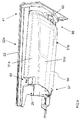
- the housing 21 is suited to receive a removable drawer 22 which can be extracted from the housing 21, such as to protrude from the cabinet 2 in an opened position, as illustrated for example in figures 1 , 2 or 3 , or can be fully inserted into the housing 21 in a closed position, such position not illustrated in the Figures.
- the drawer 22 preferably comprises a front panel 15 associated to a frontal part 41 of the drawer 22 and preferably has a handle by means of which the drawer 22 can be moved from the closed position and an opened position and, vice-versa, can be moved from the opened position to the closed position.
- the drawer 22 comprises an upper side 22a and an opposite underside 22b.
- the drawer 22 is preferably provided with one or more compartments 23a, 23b, 23c, 23d adapted to be filled with treating agents.
- compartments 23a, 23b, 23c, 23d are preferably opened upwardly to allow filling with treating agents from above.
- the number of compartments may be different, according to the desired type and number of treating agents which are used in the particular model of laundry washing machine.
- the first compartment 23a is preferably adapted for receiving a powder detergent; the second compartment 23b is preferably adapted for receiving a quantity of liquid detergent; the third compartment 23c is preferably adapted for receiving bleach; the fourth compartment 23d is preferably adapted for receiving a softener.
- treating agents such as fabric conditioners, waterproofing agents, fabric enhancers, rinse sanitization additives, chlorine-based additives, etc.
- the treating agents dispenser 20 further comprises a water distributor 35, associated to the housing 21 and placed above the drawer 22 in such a way to allow the flowing of water to one or more of said compartments 23a, 23b, 23c, 23d.
- the water distributor 35 preferably comprises one or more channels, not shown, adapted for selectively conveying water to one or more of said compartments 23a, 23b, 23c, 23d.
- the channels are opportunely shaped for conveying water to one or more of said compartments 23a, 23b, 23c, 23d of the drawer 22 when the latter is placed in its closed operative position.
- the water distributor 35 is apt to be connected to an external water source, which could comprise, for example, the plumbing of the building in which the laundry washing machine 1 is installed.
- the first water source is preferably a source for the adduction of cold water.
- the water distributor 35 is preferably connected to the external water source by means of valves 40.
- the first compartment 23a is preferably provided with an aperture 26 defined at the rear of the first compartment 23a.
- the aperture 26 is adapted to allow the flowing of a liquid therethrough and then to the side walls 21a, 21b of the housing and the outlet port 21c to convey liquid to the supply pipe towards the tub.
- the other compartments 23b, 23c and 23d of the drawer 22 are preferably provided with respective siphons 24a, 24b and 24c.
- the first siphon 24a connects the second compartment 23b to the underside 22b of the drawer 22.
- the second siphon 24b connects the third compartment 23c to the underside 22b of the drawer 22 and the third siphon 24c connects the fourth compartment 23d to the underside 22b of the drawer 22.
- Aperture 26 and siphons 24a, 24b and 24c define outlets apt to fluidly connecting a respective compartment 23a, 23b, 23c and 23d to the underside 22b of the drawer 22.
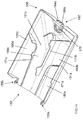
- the treating agents dispenser 20 comprises a guard element 50 movably associated to the underside 22b of the drawer 22.
- the guard element 50 according to a preferred embodiment of the invention is apt to be positioned in a first operative position, or closed position as illustrated in Figure 5 , and in a second operative position, or opened position as illustrated in Figure 6 .
- the guard element 50 preferably comprises two side lateral walls 51a, 51b and a bottom side wall 51c joining side lateral walls 51a, 51b.
- the guard element 50 therefore, is preferably U-shaped.
- the length of the guard element 50 is preferably equal to, or greater than, the length of the drawer 22.
- the width of the guard element 50 is then preferably equal to, or slightly smaller than, the width of the drawer 22.
- the guard element 50 is normally maintained in the closed position, in particular when the drawer 22 is fully inserted into the housing 21 in the closed position, which corresponds to the normal working position.
- the guard element 50 is advantageously arranged below the siphons 24a, 24b and 24c and therefore it collects the liquid coming from the siphons.
- the bottom side wall 51c of the guard element 50 is slightly inclined with respect to the horizontal plane so that to provide a ramp sloping down towards the rear side of the drawer 22.
- the liquid may therefore flow towards the rear side of the drawer 22 and in particular towards the outlet port 21c and, from there, into the supply pipe up to the tub.
- the guard element 50 advantageously guides the water and the treating agents drawn through the siphons 24a, 24b and 24c towards the tub.
- the guard element 50 also advantageously collects the liquid coming from the aperture 26 of the first compartment 23a, for example water and powder detergent, and it conveys it substantially directly to the outlet port 21c and then to the tub. This avoids, or reduces the risk, that residues of treating agent, in particular detergent, stuck at the side walls 21a, 21b of the housing 21 and/or reduces splashing of liquid.
- the liquid coming from the aperture 26 of the first compartment 23a for example water and powder detergent
- the guard element 50 substantially entirely surrounds the underside 22b of the drawer 22. This avoids, or reduces the risk, that residues of treating agent falling from the compartments 23a, 23b, 23c and 23d stuck at the side walls 21a, 21b of the housing 21 and/or reduces splashing of liquid.
- the guard element 50 is also preferably maintained in the closed position when the drawer 22 is extracted from the housing 21, such as to protrude from the cabinet 2 in an opened position, as illustrated for example in figures 1 , 2 or 3 (for example when a compartment is filled with a treating agent).
- leaking liquid from the drawer 22, for example water and/or treating agents do not fall down but again guided towards the outlet port 21c and from there into the supply pipe up to the tub. This prevent the floor getting wet.
- the guard element 50 is moved in the opened position, in particular when the drawer 22 is totally extracted from the housing 21.
- the guard element 50 in the opened position may be easily cleaned by the user, for example by flushing with water or by rubbing with a cloth.
- the guard element 50 is swingably associated to the underside 22b of the drawer 22.
- the guard element 50 is hinged to the underside 22b of the drawer 22 at the front part 41 thereof, which allows the pivoting of the guard element 50 with respect to the underside 22b of the drawer 22.
- guard element 50 is hinged at the front part 41 of the drawer 22, it has to be underlined that in different embodiments the guard element may be hinged at any different position of the underside of the drawer.
- a shaft 54 is supported by means of two ribs 55a, 55b extending from a front side 56 of the guard element 50.
- the shaft 54 is rotatably received in a seat 58 defined by a curved tongue 60 protruding from the drawer 22.
- a release device 62 then, allows a rear side 57 of the guard element 50 to be realesably connected to the underside 22b of the drawer 22.
- the release device 62 preferably comprises a first elastic tongue 64a at a first side of the guard element 50 provided with a respective first tooth 66a which is apt to be received in a corresponding first rectangular slot 70a defined in a first protruding tab 72a of the drawer 22.
- the release device 62 further preferably comprises a second elastic tongue 64b at a second side of the guard element 50 provided with a respective second tooth, not visible in the Figures, which is apt to be received in a corresponding second rectangular slot, not visible in the Figures, defined in a second protruding tab of the drawer 22.
- the second operative position of the guard element 50 is obtained by disengagement of the teeth 66a from the slots 70a by acting on the elastic tongues 64a, 64b.
- the elastic tongues 64a, 64b are deflected so that the teeth 66a disengage the slots 70a.
- the guard element 50 is then rotated around the shaft 54 and positioned in the opened position.
- the guard element 50 further to its displacement in the opened position may be preferably completely removed from the drawer 22.
- removal of the guard element 50 is obtained by forcing out the shaft 54 of the guard element 50 from the seat 58 of the drawer 22.
- the release device comprises two elastic tongues provided with teeth associated to said guard element and slots defined in protruding tabs of the drawer, it has to be underlined that in different embodiments slots may be defined in the elastic tongues and teeth may be associated to the drawer.
- the release device 62 comprises two elastic tongues provided with teeth associated to said guard element and slots defined in protruding tabs of the drawer, it has to be underlined that in different embodiments the two elastic tongues provided with teeth may be associated to the drawer and slots may be defined in the guard element.
- the number of teeth and corresponding slots may be different, even just one tooth and one slot.
- shape of the teeth and/or of the slots may be any shape suitable to obtained said releasability, as illustrated for example in embodiment illustrates in Figures 16 to 18 .
- Figures 12 to 15 illustrate a further embodiment of a drawer 122 of a treating agents dispenser according to the present invention.
- the drawer 122 comprises an upper side 122a and an opposite underside 122b.
- a guard element 150 is movably associated to the underside 122b of the drawer 122.
- the guard element 150 is apt to be positioned in a first operative position, or closed position as illustrated in Figure 12 , and in a second operative position, or opened position as illustrated in Figure 13 .
- the guard element 150 preferably comprises two side lateral walls 151a, 151b and a bottom side wall 151c joining side lateral walls 151a, 151b.
- the length of the guard element 150 is preferably equal to, or greater than, the length of the drawer 122.
- the guard element 150 is normally maintained in the closed position, in particular when the drawer 122 is fully inserted into the housing 21 in the closed position or when the drawer 122 is extracted from the housing 21, such as to protrude from the cabinet 2 in an opened position, as described above.
- leaking liquid from the drawer 122 do not fall down but are guided towards the outlet port 21c through the side walls 21a, 21b of the housing 21 and from there into the supply pipe up to the tub. This prevent the floor getting wet.
- the guard element 150 is moved in the opened position, in particular when the drawer 122 is totally extracted from the housing 21.
- the guard element 150 is swingably associated to the underside 122b of the drawer 122.
- the guard element 150 is hinged to the underside 122b of the drawer 122 at the rear part 142 thereof, which allows the pivoting of the guard element 150 with respect to the underside 122b of the drawer 122.
- Two pins 155a, 155b of the guard element 150, shown in Figure 14 are rotatably received in respective seats, non visible, defined in the drawer 122.
- a release device 162 then, allows a front side 156 of the guard element 150 to be realesably connected to the underside 122b of the drawer 122.
- the release device 162 preferably comprises an elastic tongue 164a provided with a tooth 166a at a first side of the guard element 150 which is apt to be received in a corresponding slot 170a defined at the frontal part 141 of the drawer 122.
- a closed rib 175 defines an aperture 176 wherein, advantageously, a finger of the user may be inserted.
- the tooth 166a is received in the slot 170a of the drawer 122, as illustrated in Figures 12 and 15 .
- the second operative position of the guard element 150 is obtained by disengagement of the tooth 166a from the slot 170a by acting on the elastic tongue 164a.
- the elastic tongue 164a may be deflected by the action the user's finger inserted in the aperture 176 so that the tooth 166a disengages the slot 170a.
- the guard element 150 is then rotated around the pins 155a, 155b and positioned in the opened position.
- the guard element 150 further to its displacement in the opened position may be preferably completely removed from the drawer 122.
- removal of the guard element 150 is obtained by forcing out the pins 155a, 115b from the seats of the drawer 122.
- the bottom side wall 151c of the guard element 150 is slightly inclined with respect to the horizontal plane so that to provide a ramp sloping down towards the rear side of the drawer 122.
- the inner side of the bottom side wall 151c of the guard element 150 i.e. the side facing the underside 122b of the drawer 122, is provided with ribs 171a, 171b, 171c which define respective channels 180a, 180b, 180c and 180d, as illustrated in Figure 14 .
- Channels 180a, 180b, 180c and 180d help to canalize the liquid coming from the compartments of the drawer 122 towards the outlet port 21c of the housing 21 and, from there, into the supply pipe up to the tub.
- the drawer 222 differs from the drawer 22 previously described with reference to Figures 1 to 11 in that the release device 262 comprises hemispheres 266a on elastic tongues 264a, instead of teeth 66a, which are apt to be received in corresponding oval slots 270a, instead of rectangular slots 70a.
- the present invention allows all the set objects to be achieved.
- it makes it possible to realize a laundry washing machine that makes it possible to reduce or prevent residues of treating agent in the treating agents dispensers .
- laundry washing machines illustrated in the enclosed figures are of the front-loading type; however it is clear that the system according to the invention can be applied as well to a top-loading laundry washing machine, substantially without any modification.
Landscapes
- Engineering & Computer Science (AREA)
- Textile Engineering (AREA)
- Detail Structures Of Washing Machines And Dryers (AREA)
- Main Body Construction Of Washing Machines And Laundry Dryers (AREA)
Abstract
Description
- The present invention concerns the field of laundry washing techniques.
- In particular, the present invention refers to a treating agents dispenser in a laundry washing machine.
- Nowadays the use of laundry washing machines, both "simple" laundry washing machines (i.e. laundry washing machines which can only wash and rinse laundry) and laundry washing-drying machines (i.e. laundry washing machines which can also dry laundry), is widespread.
- In the present description the term "laundry washing machine" will refer to both simple laundry washing machine and laundry washing-drying machine.
- Laundry washing machines generally comprise an external casing, or cabinet, provided with a washing tub which contains a rotatable perforated drum where the laundry is placed. A loading/unloading door ensures access to the drum.
- Laundry washing machines typically comprise a treating agents dispenser for the introduction of water and treating agents (i.e. detergent, softener, rinse conditioner, etc.) into the tub.
- Known treating agents dispensers comprise a drawer having one or more compartments adapted to be filled with at least one treating agent and one or more respective channels for conveying water to the compartments.
- Treating agents dispenser also comprises a housing on which the drawer can slide from a normal closed position to an opening position.
- The housing is typically mounted at an opening provided on the upper part of the front side of the cabinet. The opening allows entrance and exit of the drawer so that it can be positioned by the user in said positions.
- The housing of the known type preferably has a box-like structure comprising upright side walls which are connected below by a bottom side wall.
- The treating agents dispenser then comprises a water distributor which connects above the upright side walls of the housing. The water distributor is advantageously placed above the compartments and opportunely shaped to define said channels which are provided with apertures allowing water coming from an external water source to fall down in the underlying compartments.
- The bottom side wall of the housing communicates with a supply pipe connected to the tub for guiding and supplying the water, which passes through the compartments and which mixes with the treating agent, into the tub. Compartments are opportunely shaped to allow the treating agent and water flowing therethrough to reach the bottom side of the housing and then, from there, to the tub through the supply pipe.
- In preferred known embodiments, compartments comprises an aperture through which water and treating agent flow and then, from there, towards the bottom side of the housing. In further preferred known embodiments, compartments comprise a siphon. Water coming from the channel flushed into the compartment triggers the siphon and treating agent is drawn through the siphon. Treating agent and water then fall down into the housing.
- In further preferred know embodiments, compartments are shaped so that water and treating agent overflow from the compartment and fall down into the housing.
- However, the treating agents dispensers belonging to the known art poses some drawbacks.
- A first drawback posed by the treating agents dispensers of the known art and/or the laundry washing machines having such dispenser lies in that residues of treating agents, especially powder treating agents, often stuck at the side walls of the housing. Residues of treating agent may accumulate and may form a sticky, gelatinous mass, which will ultimately adhere to the side walls of the housing.
- Another drawback posed by the treating agents dispensers of the known art is that the accumulation of treating agent may favour the proliferation of bacteria, which may then worsen the hygienic conditions and may cause bad smells.
- A further drawback posed by the treating agents dispensers of the known art lies in that water and/or treating agent may leak from the drawer when the latter is extracted from the housing by the user and eventually getting the floor dirty.
- The object of the present invention is therefore to overcome the drawbacks posed by the known technique.
- It is a first object of the invention to provide a laundry washing machine that makes it possible to reduce or prevent accumulation of residues of treating agent in the treating agents dispensers.
- It is another object of the invention to provide a laundry washing machine that makes it possible to remove residues of treating agent in the treating agents dispensers.
- It is another object of the invention to provide a laundry washing machine that makes it possible to reduce proliferation of bacteria therefore improving hygienic conditions.
- It is a further object of the invention to provide a laundry washing machine that makes it possible to avoid housecleaning.
- The applicant has found that by providing a laundry washing machine having a treating agents dispenser comprising a drawer having one or more compartments for receiving at least one agent for treating laundry wherein a guard element is movably connected to an underside of the drawer, it is possible to reduce or prevent accumulation of residues of treating agent in the treating agents dispenser or allowing removal of residues compared to known techniques.
- Advantageously, the guard element may be easily moved in an opened position with respect to the drawer and then cleaned by the user.
- The present invention relates, therefore, to a laundry washing machine connectable to an external water source comprising a cabinet supporting a washing tub enclosing a rotatable washing drum suited to receive laundry and a treating agents dispenser connectable to said external water source and fluidly connected to said washing tub, said treating agents dispenser comprising:
- a drawer comprising one or more compartments for receiving at least one agent for treating laundry;
- a supporting structure on which said drawer can slide;
- a water distributor comprising at least one channel for conveying water from said external water source to at least one of said one or more compartments of said drawer;
- According to a preferred embodiment of the invention, the guard element is swingably connected to the underside of said drawer.
- According to another preferred embodiment of the invention, the guard element is removably connected to the underside of the drawer.
- Preferably, the guard element is hinged to the underside of the drawer to allow the pivoting of the guard element with respect to the underside of the drawer.
- In a preferred embodiment of the invention, the guard element is hinged to the underside of the drawer at a front part thereof.
- In another preferred embodiment of the invention, the guard element is hinged to the underside of the drawer at a rear part thereof.
- According to a preferred embodiment of the invention, the treating agents dispenser comprises a release device realesably connecting the guard element to the underside of the drawer.
- Preferably, the release device comprises an elastic tongue provided with a tooth associated to the guard element or the drawer, the tooth being apt to be received in a slot associated to the drawer or the guard element, respectively.
- In a further preferred embodiment of the invention, the release device comprises an elastic tongue provided with a slot associated to the guard element or the drawer, the slot being apt to receive a tooth associated to the drawer or the guard element, respectively.
- According to a preferred embodiment of the invention, a side of the guard element facing the underside of the drawer comprises at least one rib defining at least one channel apt to canalize liquid therethrough.
- Preferably, at least one of said one or more compartments comprises and outlet apt to fluidly connecting said at least one of said one or more compartments to the underside of the drawer. In a preferred embodiment of the invention, the outlet comprises a siphon.
- According to a preferred embodiment of the invention, the guard element comprises two side lateral walls and a bottom side wall joining said side lateral walls.
- Preferably, the length of the guard element is equal to, or greater than, the length of the drawer.
- Preferably, the width of the guard element is equal to, or slightly smaller than, the width of the drawer.
- According to a preferred embodiment of the invention, the water distributor is placed above the drawer when the treating agents dispenser is mounted in an operational position.
- Preferably, the drawer is slidable from a closed position to an opened position or from an opened position to a closed position.
- Further characteristics and advantages of the present invention will be highlighted in greater detail in the following detailed description of preferred embodiments of the invention, provided with reference to the enclosed drawings.
- In the drawings, corresponding characteristics and/or components are identified by the same reference numbers. In such drawings:
-
Figure 1 shows a perspective view of a laundry washing machine equipped with a treating agents dispenser with the drawer in an opened position according to a preferred embodiment of the invention; -
Figure 2 shows the laundry washing machine ofFigure 1 with the upper side wall removed therefrom; -
Figure 3 shows the laundry washing machine ofFigure 2 with an element of the treating agents dispenser removed therefrom; -
Figure 4 is a plan view from above of the drawer ofFigure 3 ; -
Figure 5 is a perspective view from below of the drawer ofFigure 4 in a first operative condition; -
Figure 6 shows the drawer ofFigure 5 in a different operative condition; -
Figure 7 shows an enlarged view of a detail ofFigure 5 ; -
Figure 8 shows the detail ofFigure 7 in a different operative condition; -
Figure 9 shows a plan view ofFigure 7 sectioned along line IX°-IX°; -
Figure 10 shows an enlarged view of a detail ofFigure 5 from another point of view; -
Figure 11 shows a plan view ofFigure 10 sectioned along line XI°-XI°; -
Figure 12 is a perspective view from below of a drawer in a first operative condition according to a further preferred embodiment of the invention; -
Figure 13 shows the drawer ofFigure 12 in a different operative condition; -
Figure 14 is a perspective view of an element ofFigure 13 isolated from the rest; -
Figure 15 shows a plan view ofFigure 12 sectioned along line XV°-XV°; -
Figure 16 is a perspective view from below of a drawer in an operative condition according to a further preferred embodiment of the invention; -
Figure 17 is a perspective view of a detail of the drawer ofFigure 16 in a closed position; -
Figure 18 shows a plan view ofFigure 17 sectioned along line XVIII°-XVIII°. - The present invention has proved to be particularly advantageous when applied to laundry washing machines, as described below. It should in any case be underlined that the present invention is not limited to laundry washing machines.
- On the contrary, the present invention can be conveniently applied to laundry washing-drying machines (i.e. laundry washing machines which can also dry laundry).
- In the present description, therefore, the term "laundry washing machine" will refer to both simple laundry washing machine and laundry washing-drying machine.
- A
laundry washing machine 1 equipped with a treatingagents dispenser 20 according to a preferred embodiment of the invention is described with reference toFigures 1 to 11 . - The
laundry washing machine 1 comprises an external casing orcabinet 2, in which a washing tub, not shown, is provided that contains a perforated washing drum, not shown, where the laundry to be treated can be loaded. Thecabinet 2 comprises a verticalfront side wall 2a, a verticalrear side wall 2b, two verticallateral side walls upper side wall 2e. - The
cabinet 2 is provided with a loading/unloading door 8 which allows access to the drum. -
Laundry washing machine 1 advantageously comprises a control unit (not shown), connected to the various parts of thelaundry washing machine 1 in order to ensure its operation.Laundry washing machine 1 preferably comprises aninterface unit 16, connected to the control unit, accessible to the user and by means of which the user may select and set the washing parameters, like for example a desired washing program. Usually, other parameters can optionally be inserted by the user, for example the washing temperature, the spinning speed, etc.. Theinterface unit 16 preferably comprises adisplay 16a which displays machine working conditions. - The
unit interface 16 then preferably comprises one or more selector devices which allow to select the appropriate washing program and/or to set other parameters. - The
laundry washing machine 1 advantageously comprises said treatingagents dispenser 20 to supply treating agents into the tub during a washing cycle. - Treating agents may comprise, for example, detergents, rinse additives, fabric softeners or fabric conditioners, waterproofing agents, fabric enhancers, rinse sanitization additives, chlorine-based additives, etc..
- Advantageously, the treating
agents dispenser 20 comprises a box-shapedhousing 21, connected to thecabinet 2, internally to the latter, preferably by suitable fixing means, comprising, for example, screws or rivets, not illustrated, or also glue, or welding. - In the enclosed Figures, the
housing 21 is advantageously substantially prism shaped, and it is connected to thefrontal side wall 2a of thecabinet 2, opportunely in an upper region of the latter, positioned above the tub. - The
housing 21 preferably comprises twoinclined side walls Figure 3 . - An
outlet port 21c is preferably defined at the rear portion of thehousing 21. Theoutlet port 21c is adapted to allow the flowing of a liquid into a supply pipe (not shown) fluidly connecting the treatingagents dispenser 20 to the tub. - The
housing 21 is suited to receive aremovable drawer 22 which can be extracted from thehousing 21, such as to protrude from thecabinet 2 in an opened position, as illustrated for example infigures 1 ,2 or3 , or can be fully inserted into thehousing 21 in a closed position, such position not illustrated in the Figures. - The
drawer 22 preferably comprises afront panel 15 associated to afrontal part 41 of thedrawer 22 and preferably has a handle by means of which thedrawer 22 can be moved from the closed position and an opened position and, vice-versa, can be moved from the opened position to the closed position. - The
drawer 22 comprises anupper side 22a and anopposite underside 22b. - The
drawer 22 is preferably provided with one ormore compartments - The
compartments - In the embodiment illustrated in the Figures, there are four compartments, 23a, 23b, 23c and 23d.
- In different embodiments, not illustrated, the number of compartments may be different, according to the desired type and number of treating agents which are used in the particular model of laundry washing machine.
- The
first compartment 23a is preferably adapted for receiving a powder detergent; thesecond compartment 23b is preferably adapted for receiving a quantity of liquid detergent; thethird compartment 23c is preferably adapted for receiving bleach; thefourth compartment 23d is preferably adapted for receiving a softener. - In different embodiments, other treating agents may be used, such as fabric conditioners, waterproofing agents, fabric enhancers, rinse sanitization additives, chlorine-based additives, etc.
- The treating
agents dispenser 20 further comprises awater distributor 35, associated to thehousing 21 and placed above thedrawer 22 in such a way to allow the flowing of water to one or more of saidcompartments - At this purpose, the
water distributor 35 preferably comprises one or more channels, not shown, adapted for selectively conveying water to one or more of saidcompartments - The channels are opportunely shaped for conveying water to one or more of said
compartments drawer 22 when the latter is placed in its closed operative position. - The
water distributor 35 is apt to be connected to an external water source, which could comprise, for example, the plumbing of the building in which thelaundry washing machine 1 is installed. The first water source is preferably a source for the adduction of cold water. - The
water distributor 35 is preferably connected to the external water source by means ofvalves 40. - The
first compartment 23a is preferably provided with anaperture 26 defined at the rear of thefirst compartment 23a. Theaperture 26 is adapted to allow the flowing of a liquid therethrough and then to theside walls outlet port 21c to convey liquid to the supply pipe towards the tub. - The
other compartments drawer 22 are preferably provided withrespective siphons - The first siphon 24a connects the
second compartment 23b to theunderside 22b of thedrawer 22. Analogously, the second siphon 24b connects thethird compartment 23c to theunderside 22b of thedrawer 22 and the third siphon 24c connects thefourth compartment 23d to theunderside 22b of thedrawer 22. -
Aperture 26 and siphons 24a, 24b and 24c define outlets apt to fluidly connecting arespective compartment underside 22b of thedrawer 22. - According to an aspect of the invention, the treating
agents dispenser 20 comprises aguard element 50 movably associated to theunderside 22b of thedrawer 22. - The
guard element 50 according to a preferred embodiment of the invention is apt to be positioned in a first operative position, or closed position as illustrated inFigure 5 , and in a second operative position, or opened position as illustrated inFigure 6 . - The
guard element 50 preferably comprises two sidelateral walls bottom side wall 51c joining sidelateral walls guard element 50, therefore, is preferably U-shaped. - The length of the
guard element 50 is preferably equal to, or greater than, the length of thedrawer 22. - The width of the
guard element 50 is then preferably equal to, or slightly smaller than, the width of thedrawer 22. - The
guard element 50 is normally maintained in the closed position, in particular when thedrawer 22 is fully inserted into thehousing 21 in the closed position, which corresponds to the normal working position. - The
guard element 50 is advantageously arranged below thesiphons - In a preferred embodiment, the
bottom side wall 51c of theguard element 50 is slightly inclined with respect to the horizontal plane so that to provide a ramp sloping down towards the rear side of thedrawer 22. The liquid may therefore flow towards the rear side of thedrawer 22 and in particular towards theoutlet port 21c and, from there, into the supply pipe up to the tub. - The
guard element 50 advantageously guides the water and the treating agents drawn through thesiphons - Furthermore, in particular when the length of the
guard element 50 is greater than the length of thedrawer 22, theguard element 50 also advantageously collects the liquid coming from theaperture 26 of thefirst compartment 23a, for example water and powder detergent, and it conveys it substantially directly to theoutlet port 21c and then to the tub. This avoids, or reduces the risk, that residues of treating agent, in particular detergent, stuck at theside walls housing 21 and/or reduces splashing of liquid. - Furthermore, advantageously, in particular when the width of the
guard element 50 is equal to the width of thedrawer 22, theguard element 50 substantially entirely surrounds theunderside 22b of thedrawer 22. This avoids, or reduces the risk, that residues of treating agent falling from thecompartments side walls housing 21 and/or reduces splashing of liquid. - The
guard element 50 is also preferably maintained in the closed position when thedrawer 22 is extracted from thehousing 21, such as to protrude from thecabinet 2 in an opened position, as illustrated for example infigures 1 ,2 or3 (for example when a compartment is filled with a treating agent). - Advantageously, leaking liquid from the
drawer 22, for example water and/or treating agents, do not fall down but again guided towards theoutlet port 21c and from there into the supply pipe up to the tub. This prevent the floor getting wet. - According to a further aspect of the invention, the
guard element 50 is moved in the opened position, in particular when thedrawer 22 is totally extracted from thehousing 21. - The
guard element 50 in the opened position may be easily cleaned by the user, for example by flushing with water or by rubbing with a cloth. - Accumulation of residues of treating agents is therefore prevented. This guarantees good hygienic conditions of the
guard element 50 and of the treatingagents dispenser 20, in particular when thelaundry washing machine 1 in not used for a long time between two successive washing cycles. - More preferably, the
guard element 50 is swingably associated to theunderside 22b of thedrawer 22. Theguard element 50 is hinged to theunderside 22b of thedrawer 22 at thefront part 41 thereof, which allows the pivoting of theguard element 50 with respect to theunderside 22b of thedrawer 22. - While in the preferred embodiment illustrated the
guard element 50 is hinged at thefront part 41 of thedrawer 22, it has to be underlined that in different embodiments the guard element may be hinged at any different position of the underside of the drawer. - As illustrated in
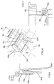
Figures 10 and 11 , ashaft 54 is supported by means of tworibs front side 56 of theguard element 50. Theshaft 54 is rotatably received in aseat 58 defined by acurved tongue 60 protruding from thedrawer 22. - A
release device 62, then, allows arear side 57 of theguard element 50 to be realesably connected to theunderside 22b of thedrawer 22. - The
release device 62 preferably comprises a firstelastic tongue 64a at a first side of theguard element 50 provided with a respectivefirst tooth 66a which is apt to be received in a corresponding firstrectangular slot 70a defined in a first protrudingtab 72a of thedrawer 22. - The
release device 62 further preferably comprises a secondelastic tongue 64b at a second side of theguard element 50 provided with a respective second tooth, not visible in the Figures, which is apt to be received in a corresponding second rectangular slot, not visible in the Figures, defined in a second protruding tab of thedrawer 22. - In the first operative position of the
guard element 50, theteeth 66a are received in theslots 70a of thetabs 72a, as illustrated inFigure 7 . - The second operative position of the
guard element 50 is obtained by disengagement of theteeth 66a from theslots 70a by acting on theelastic tongues elastic tongues teeth 66a disengage theslots 70a. Theguard element 50 is then rotated around theshaft 54 and positioned in the opened position. - More preferably, the
guard element 50 further to its displacement in the opened position may be preferably completely removed from thedrawer 22. - In the preferred embodiment above described, removal of the
guard element 50 is obtained by forcing out theshaft 54 of theguard element 50 from theseat 58 of thedrawer 22. - Removal of the
guard element 50 make the cleaning operations easy. - While in the preferred embodiment illustrated the release device comprises two elastic tongues provided with teeth associated to said guard element and slots defined in protruding tabs of the drawer, it has to be underlined that in different embodiments slots may be defined in the elastic tongues and teeth may be associated to the drawer.
- Furthermore, while in the preferred embodiment illustrated the
release device 62 comprises two elastic tongues provided with teeth associated to said guard element and slots defined in protruding tabs of the drawer, it has to be underlined that in different embodiments the two elastic tongues provided with teeth may be associated to the drawer and slots may be defined in the guard element. - In different embodiments, then, the number of teeth and corresponding slots may be different, even just one tooth and one slot.
- It has to be understood that shape of the teeth and/or of the slots may be any shape suitable to obtained said releasability, as illustrated for example in embodiment illustrates in
Figures 16 to 18 . -
Figures 12 to 15 illustrate a further embodiment of adrawer 122 of a treating agents dispenser according to the present invention. - The
drawer 122 comprises anupper side 122a and anopposite underside 122b. Aguard element 150 is movably associated to theunderside 122b of thedrawer 122. - The
guard element 150 is apt to be positioned in a first operative position, or closed position as illustrated inFigure 12 , and in a second operative position, or opened position as illustrated inFigure 13 . - The
guard element 150 preferably comprises twoside lateral walls bottom side wall 151c joining sidelateral walls - The length of the
guard element 150 is preferably equal to, or greater than, the length of thedrawer 122. - The
guard element 150 is normally maintained in the closed position, in particular when thedrawer 122 is fully inserted into thehousing 21 in the closed position or when thedrawer 122 is extracted from thehousing 21, such as to protrude from thecabinet 2 in an opened position, as described above. - Advantageously, leaking liquid from the
drawer 122, for example water and/or treating agents, do not fall down but are guided towards theoutlet port 21c through theside walls housing 21 and from there into the supply pipe up to the tub. This prevent the floor getting wet. - The
guard element 150 is moved in the opened position, in particular when thedrawer 122 is totally extracted from thehousing 21. - More preferably, the
guard element 150 is swingably associated to theunderside 122b of thedrawer 122. Theguard element 150 is hinged to theunderside 122b of thedrawer 122 at therear part 142 thereof, which allows the pivoting of theguard element 150 with respect to theunderside 122b of thedrawer 122. - Two
pins guard element 150, shown inFigure 14 , are rotatably received in respective seats, non visible, defined in thedrawer 122. - A
release device 162, then, allows afront side 156 of theguard element 150 to be realesably connected to theunderside 122b of thedrawer 122. - The
release device 162 preferably comprises anelastic tongue 164a provided with atooth 166a at a first side of theguard element 150 which is apt to be received in acorresponding slot 170a defined at thefrontal part 141 of thedrawer 122. Aclosed rib 175 defines anaperture 176 wherein, advantageously, a finger of the user may be inserted. - In the first operative position of the
guard element 150, thetooth 166a is received in theslot 170a of thedrawer 122, as illustrated inFigures 12 and15 . - The second operative position of the
guard element 150 is obtained by disengagement of thetooth 166a from theslot 170a by acting on theelastic tongue 164a. In particular, theelastic tongue 164a may be deflected by the action the user's finger inserted in theaperture 176 so that thetooth 166a disengages theslot 170a. Theguard element 150 is then rotated around thepins - More preferably, the
guard element 150 further to its displacement in the opened position may be preferably completely removed from thedrawer 122. - In the preferred embodiment above described, removal of the
guard element 150 is obtained by forcing out thepins 155a, 115b from the seats of thedrawer 122. - The
bottom side wall 151c of theguard element 150 is slightly inclined with respect to the horizontal plane so that to provide a ramp sloping down towards the rear side of thedrawer 122. - Preferably, the inner side of the
bottom side wall 151c of theguard element 150, i.e. the side facing theunderside 122b of thedrawer 122, is provided withribs respective channels Figure 14 . -
Channels drawer 122 towards theoutlet port 21c of thehousing 21 and, from there, into the supply pipe up to the tub. - With reference to
Figures 16 to 18 adrawer 222 according to a further preferred embodiment of the invention is described. - The
drawer 222 differs from thedrawer 22 previously described with reference toFigures 1 to 11 in that therelease device 262 compriseshemispheres 266a onelastic tongues 264a, instead ofteeth 66a, which are apt to be received in correspondingoval slots 270a, instead ofrectangular slots 70a. - This preferred embodiment achieves all the advantages above described for the previous embodiments.
- It has thus been shown that the present invention allows all the set objects to be achieved. In particular, it makes it possible to realize a laundry washing machine that makes it possible to reduce or prevent residues of treating agent in the treating agents dispensers .
- It is underlined that the laundry washing machines illustrated in the enclosed figures are of the front-loading type; however it is clear that the system according to the invention can be applied as well to a top-loading laundry washing machine, substantially without any modification.
- While the present invention has been described with reference to the particular embodiments shown in the figures, it should be noted that the present invention is not limited to the specific embodiments illustrated and described herein; on the contrary, further variants of the embodiments described herein fall within the scope of the present invention, which is defined in the claims.
Claims (15)
- A laundry washing machine (1) connectable to an external water source comprising a cabinet (2) supporting a washing tub enclosing a rotatable washing drum suited to receive laundry and a treating agents dispenser (20) connectable to said external water source and fluidly connected to said washing tub, said treating agents dispenser (20) comprising:- a drawer (22; 122; 222) comprising one or more compartments (23a, 23b, 23c, 23d) for receiving at least one agent for treating laundry;- a supporting structure (21) on which said drawer (22; 122; 222) can slide;- a water distributor (35) comprising at least one channel for conveying water from said external water source to at least one of said one or more compartments (23a, 23b, 23c, 23d) of said drawer (22; 122; 222);wherein a guard element (50; 150) is movably connected to an underside (22b; 122b) of said drawer (22; 122; 222).
- A machine (1) according to claim 1, wherein said guard element (50; 150) is swingably connected to said underside (22b; 122b) of said drawer (22; 122; 222).
- A machine (1) according to claim 1 or 2, wherein said guard element (50; 150) is removably connected to said underside (22b; 122b) of said drawer (22; 122; 222).
- A machine (1) according to any of the preceding claims, wherein said guard element (50; 150) is hinged to said underside (22b; 122b) of said drawer (22; 122; 222) to allow the pivoting of said guard element (50; 150) with respect to said underside (22b; 122b) of said drawer (22; 122; 222).
- A machine (1) according to claim 4, wherein said guard element (50; 150) is hinged to said underside (22b; 122b) of said drawer (22; 122; 222) at a front part thereof (41) or at a rear part thereof (142).
- A machine (1) according to any of the preceding claims, wherein treating agents dispenser (10) comprises a release device (62; 162; 262) realesably connecting said guard element (50; 150) to said underside (22b; 122b) of said drawer (22; 122; 222).
- A machine (1) according to claim 6, wherein said release device (62; 162; 262) comprises an elastic tongue (64a; 164a; 264a) provided with a tooth (66a; 166a; 266a) associated to said guard element (50; 150) or said drawer (22; 122; 222), said tooth (66a; 166a; 266a) being apt to be received in a slot (70a; 270a) associated to said drawer (22; 122; 222) or said guard element (50; 150), respectively.
- A machine (1) according to claim 6, wherein said release device comprises an elastic tongue provided with a slot associated to said guard element or said drawer, said slot being apt to receive a tooth associated to said drawer or said guard element, respectively.
- A machine (1) according to any of the preceding claims, wherein a side of said guard element (150) facing said underside (122b) of said drawer (122) comprises at least one rib (171a, 171b, 171c) defining at least one channel (180a, 180b, 180c) apt to canalize liquid therethrough.
- A machine (1) according to any of the preceding claims, wherein at least one of said one or more compartments (23a, 23b, 23c, 23d) comprises and outlet (26, 24a, 24b, 24c, 24d) apt to fluidly connecting said at least one of said one or more compartments (23a, 23b, 23c, 23d) to said underside (22b; 122b) of said drawer (22; 122; 222).
- A machine (1) according to claim 10, wherein said outlet comprises a siphon (24a, 24b, 24c, 24d).
- A machine (1) according to any of the preceding claims, wherein said guard element (50; 150) comprises two side lateral walls (51a, 51b; 151a, 151b) and a bottom side wall (51c; 151c) joining said side lateral walls (51a, 51b; 151a, 151b).
- A machine (1) according to any of the preceding claims, wherein the length of said guard element (50; 150) is equal to, or greater than, the length of said drawer (22; 122; 222).
- A machine (1) according to any of the preceding claims, wherein said water distributor (35) is placed above said drawer (22; 122; 222) when said treating agents dispenser (10) is mounted in an operational position.
- A machine (1) according to any of the preceding claims, wherein said drawer (22; 122; 222) is slidable from a closed position to an opened position or from an opened position to a closed position.
Priority Applications (2)
| Application Number | Priority Date | Filing Date | Title |
|---|---|---|---|
| EP16180617.9A EP3272930B1 (en) | 2016-07-21 | 2016-07-21 | Laundry washing machine equipped with a treating agents dispenser |
| PCT/EP2017/066602 WO2018015140A1 (en) | 2016-07-21 | 2017-07-04 | Laundry washing machine equipped with a treating agents dispenser |
Applications Claiming Priority (1)
| Application Number | Priority Date | Filing Date | Title |
|---|---|---|---|
| EP16180617.9A EP3272930B1 (en) | 2016-07-21 | 2016-07-21 | Laundry washing machine equipped with a treating agents dispenser |
Publications (2)
| Publication Number | Publication Date |
|---|---|
| EP3272930A1 true EP3272930A1 (en) | 2018-01-24 |
| EP3272930B1 EP3272930B1 (en) | 2021-02-24 |
Family
ID=56507486
Family Applications (1)
| Application Number | Title | Priority Date | Filing Date |
|---|---|---|---|
| EP16180617.9A Active EP3272930B1 (en) | 2016-07-21 | 2016-07-21 | Laundry washing machine equipped with a treating agents dispenser |
Country Status (2)
| Country | Link |
|---|---|
| EP (1) | EP3272930B1 (en) |
| WO (1) | WO2018015140A1 (en) |
Cited By (1)
| Publication number | Priority date | Publication date | Assignee | Title |
|---|---|---|---|---|
| EP3617378A1 (en) * | 2018-08-30 | 2020-03-04 | Electrolux Appliances Aktiebolag | Laundry appliance with improved drawer |
Citations (3)
| Publication number | Priority date | Publication date | Assignee | Title |
|---|---|---|---|---|
| US20030145633A1 (en) * | 2002-02-06 | 2003-08-07 | Merkle Scott A. | Dual use detergent dispenser |
| US20100095712A1 (en) * | 2008-10-17 | 2010-04-22 | Bo Yeon Kim | Fluid detergent and fabric softner box assembly for laundry machine and detergent dispenser having the same |
| EP2503049A1 (en) * | 2011-03-25 | 2012-09-26 | Miele & Cie. KG | Feed-in device for a washing machine with a push-in drawer |
-
2016
- 2016-07-21 EP EP16180617.9A patent/EP3272930B1/en active Active
-
2017
- 2017-07-04 WO PCT/EP2017/066602 patent/WO2018015140A1/en active Application Filing
Patent Citations (3)
| Publication number | Priority date | Publication date | Assignee | Title |
|---|---|---|---|---|
| US20030145633A1 (en) * | 2002-02-06 | 2003-08-07 | Merkle Scott A. | Dual use detergent dispenser |
| US20100095712A1 (en) * | 2008-10-17 | 2010-04-22 | Bo Yeon Kim | Fluid detergent and fabric softner box assembly for laundry machine and detergent dispenser having the same |
| EP2503049A1 (en) * | 2011-03-25 | 2012-09-26 | Miele & Cie. KG | Feed-in device for a washing machine with a push-in drawer |
Cited By (5)
| Publication number | Priority date | Publication date | Assignee | Title |
|---|---|---|---|---|
| EP3617378A1 (en) * | 2018-08-30 | 2020-03-04 | Electrolux Appliances Aktiebolag | Laundry appliance with improved drawer |
| WO2020043627A1 (en) * | 2018-08-30 | 2020-03-05 | Electrolux Appliances Aktiebolag | Laundry appliance with improved drawer |
| CN112585314A (en) * | 2018-08-30 | 2021-03-30 | 伊莱克斯家用电器股份公司 | Laundry appliance with improved drawer |
| CN112585314B (en) * | 2018-08-30 | 2023-09-19 | 伊莱克斯家用电器股份公司 | Laundry appliance with improved drawer |
| US11802362B2 (en) | 2018-08-30 | 2023-10-31 | Electrolux Appliances Aktiebolag | Laundry appliance with improved drawer |
Also Published As
| Publication number | Publication date |
|---|---|
| EP3272930B1 (en) | 2021-02-24 |
| WO2018015140A1 (en) | 2018-01-25 |
Similar Documents
| Publication | Publication Date | Title |
|---|---|---|
| US10316455B2 (en) | Laundry washing machine equipped with a treating agents dispenser having water supplying apparatus | |
| US9644308B2 (en) | Nozzle formed in a dispensing apparatus | |
| US7481082B2 (en) | Detergent supply apparatus of washing machine | |
| EP2239364B1 (en) | Washing machine with an improved washing/rinsing-liquid inlet circuit | |
| US11255038B2 (en) | Laundry washing machine equipped with a treating agents dispenser | |
| US20150345069A1 (en) | Dispensing apparatus with labyrinth seal | |
| EP2241669A1 (en) | Washing machine with an improved washing/rinsing-liquid inlet circuit | |
| US3727434A (en) | Additive dispensing system | |
| KR100873681B1 (en) | Top loader type washing machine | |
| US10422073B2 (en) | Laundry washing machine equipped with a treating agents dispenser having water supplying apparatus | |
| US20130180293A1 (en) | Washing machine soap and chemical dispenser with improved flushing | |
| US3760612A (en) | Additive dispensing system | |
| KR100830488B1 (en) | device for providing detergent in washing machine | |
| EP3272930B1 (en) | Laundry washing machine equipped with a treating agents dispenser | |
| KR20130033225A (en) | Detergent dispenser and clothes treating apparatus with the same | |
| US20170298562A1 (en) | Washing Machine Appliance with a Fluid Additive Receptacle | |
| US9103062B2 (en) | Appliance with features for preventing additive drying | |
| KR100830487B1 (en) | device for providing detergent in washing machine | |
| EP3985161B1 (en) | Laundry treating apparatus | |
| KR20070066596A (en) | Detergent applying apparatus of washing machine | |
| KR20140011192A (en) | Detergent supply device of laundry treatment machine | |
| KR20190009727A (en) | Laundry Treating Apparatus | |
| KR20070066595A (en) | Detergent applying apparatus of washing machine |
Legal Events
| Date | Code | Title | Description |
|---|---|---|---|
| PUAI | Public reference made under article 153(3) epc to a published international application that has entered the european phase |
Free format text: ORIGINAL CODE: 0009012 |
|
| STAA | Information on the status of an ep patent application or granted ep patent |
Free format text: STATUS: THE APPLICATION HAS BEEN PUBLISHED |
|
| AK | Designated contracting states |
Kind code of ref document: A1 Designated state(s): AL AT BE BG CH CY CZ DE DK EE ES FI FR GB GR HR HU IE IS IT LI LT LU LV MC MK MT NL NO PL PT RO RS SE SI SK SM TR |
|
| AX | Request for extension of the european patent |
Extension state: BA ME |
|
| STAA | Information on the status of an ep patent application or granted ep patent |
Free format text: STATUS: REQUEST FOR EXAMINATION WAS MADE |
|
| 17P | Request for examination filed |
Effective date: 20180724 |
|
| RBV | Designated contracting states (corrected) |
Designated state(s): AL AT BE BG CH CY CZ DE DK EE ES FI FR GB GR HR HU IE IS IT LI LT LU LV MC MK MT NL NO PL PT RO RS SE SI SK SM TR |
|
| GRAP | Despatch of communication of intention to grant a patent |
Free format text: ORIGINAL CODE: EPIDOSNIGR1 |
|
| STAA | Information on the status of an ep patent application or granted ep patent |
Free format text: STATUS: GRANT OF PATENT IS INTENDED |
|
| INTG | Intention to grant announced |
Effective date: 20200922 |
|
| GRAS | Grant fee paid |
Free format text: ORIGINAL CODE: EPIDOSNIGR3 |
|
| GRAA | (expected) grant |
Free format text: ORIGINAL CODE: 0009210 |
|
| STAA | Information on the status of an ep patent application or granted ep patent |
Free format text: STATUS: THE PATENT HAS BEEN GRANTED |
|
| AK | Designated contracting states |
Kind code of ref document: B1 Designated state(s): AL AT BE BG CH CY CZ DE DK EE ES FI FR GB GR HR HU IE IS IT LI LT LU LV MC MK MT NL NO PL PT RO RS SE SI SK SM TR |
|
| REG | Reference to a national code |
Ref country code: CH Ref legal event code: EP |
|
| REG | Reference to a national code |
Ref country code: AT Ref legal event code: REF Ref document number: 1364567 Country of ref document: AT Kind code of ref document: T Effective date: 20210315 |
|
| REG | Reference to a national code |
Ref country code: IE Ref legal event code: FG4D |
|
| REG | Reference to a national code |
Ref country code: DE Ref legal event code: R096 Ref document number: 602016052988 Country of ref document: DE |
|
| REG | Reference to a national code |
Ref country code: LT Ref legal event code: MG9D |
|
| REG | Reference to a national code |
Ref country code: NL Ref legal event code: MP Effective date: 20210224 |
|
| PG25 | Lapsed in a contracting state [announced via postgrant information from national office to epo] |
Ref country code: BG Free format text: LAPSE BECAUSE OF FAILURE TO SUBMIT A TRANSLATION OF THE DESCRIPTION OR TO PAY THE FEE WITHIN THE PRESCRIBED TIME-LIMIT Effective date: 20210524 Ref country code: GR Free format text: LAPSE BECAUSE OF FAILURE TO SUBMIT A TRANSLATION OF THE DESCRIPTION OR TO PAY THE FEE WITHIN THE PRESCRIBED TIME-LIMIT Effective date: 20210525 Ref country code: HR Free format text: LAPSE BECAUSE OF FAILURE TO SUBMIT A TRANSLATION OF THE DESCRIPTION OR TO PAY THE FEE WITHIN THE PRESCRIBED TIME-LIMIT Effective date: 20210224 Ref country code: FI Free format text: LAPSE BECAUSE OF FAILURE TO SUBMIT A TRANSLATION OF THE DESCRIPTION OR TO PAY THE FEE WITHIN THE PRESCRIBED TIME-LIMIT Effective date: 20210224 Ref country code: LT Free format text: LAPSE BECAUSE OF FAILURE TO SUBMIT A TRANSLATION OF THE DESCRIPTION OR TO PAY THE FEE WITHIN THE PRESCRIBED TIME-LIMIT Effective date: 20210224 Ref country code: NO Free format text: LAPSE BECAUSE OF FAILURE TO SUBMIT A TRANSLATION OF THE DESCRIPTION OR TO PAY THE FEE WITHIN THE PRESCRIBED TIME-LIMIT Effective date: 20210524 Ref country code: PT Free format text: LAPSE BECAUSE OF FAILURE TO SUBMIT A TRANSLATION OF THE DESCRIPTION OR TO PAY THE FEE WITHIN THE PRESCRIBED TIME-LIMIT Effective date: 20210624 |
|
| REG | Reference to a national code |
Ref country code: AT Ref legal event code: MK05 Ref document number: 1364567 Country of ref document: AT Kind code of ref document: T Effective date: 20210224 |
|
| PG25 | Lapsed in a contracting state [announced via postgrant information from national office to epo] |
Ref country code: SE Free format text: LAPSE BECAUSE OF FAILURE TO SUBMIT A TRANSLATION OF THE DESCRIPTION OR TO PAY THE FEE WITHIN THE PRESCRIBED TIME-LIMIT Effective date: 20210224 Ref country code: PL Free format text: LAPSE BECAUSE OF FAILURE TO SUBMIT A TRANSLATION OF THE DESCRIPTION OR TO PAY THE FEE WITHIN THE PRESCRIBED TIME-LIMIT Effective date: 20210224 Ref country code: RS Free format text: LAPSE BECAUSE OF FAILURE TO SUBMIT A TRANSLATION OF THE DESCRIPTION OR TO PAY THE FEE WITHIN THE PRESCRIBED TIME-LIMIT Effective date: 20210224 Ref country code: LV Free format text: LAPSE BECAUSE OF FAILURE TO SUBMIT A TRANSLATION OF THE DESCRIPTION OR TO PAY THE FEE WITHIN THE PRESCRIBED TIME-LIMIT Effective date: 20210224 Ref country code: NL Free format text: LAPSE BECAUSE OF FAILURE TO SUBMIT A TRANSLATION OF THE DESCRIPTION OR TO PAY THE FEE WITHIN THE PRESCRIBED TIME-LIMIT Effective date: 20210224 |
|
| PG25 | Lapsed in a contracting state [announced via postgrant information from national office to epo] |
Ref country code: IS Free format text: LAPSE BECAUSE OF FAILURE TO SUBMIT A TRANSLATION OF THE DESCRIPTION OR TO PAY THE FEE WITHIN THE PRESCRIBED TIME-LIMIT Effective date: 20210624 |
|
| PG25 | Lapsed in a contracting state [announced via postgrant information from national office to epo] |
Ref country code: CZ Free format text: LAPSE BECAUSE OF FAILURE TO SUBMIT A TRANSLATION OF THE DESCRIPTION OR TO PAY THE FEE WITHIN THE PRESCRIBED TIME-LIMIT Effective date: 20210224 Ref country code: EE Free format text: LAPSE BECAUSE OF FAILURE TO SUBMIT A TRANSLATION OF THE DESCRIPTION OR TO PAY THE FEE WITHIN THE PRESCRIBED TIME-LIMIT Effective date: 20210224 Ref country code: AT Free format text: LAPSE BECAUSE OF FAILURE TO SUBMIT A TRANSLATION OF THE DESCRIPTION OR TO PAY THE FEE WITHIN THE PRESCRIBED TIME-LIMIT Effective date: 20210224 Ref country code: SM Free format text: LAPSE BECAUSE OF FAILURE TO SUBMIT A TRANSLATION OF THE DESCRIPTION OR TO PAY THE FEE WITHIN THE PRESCRIBED TIME-LIMIT Effective date: 20210224 |
|
| REG | Reference to a national code |
Ref country code: DE Ref legal event code: R097 Ref document number: 602016052988 Country of ref document: DE |
|
| PG25 | Lapsed in a contracting state [announced via postgrant information from national office to epo] |
Ref country code: DK Free format text: LAPSE BECAUSE OF FAILURE TO SUBMIT A TRANSLATION OF THE DESCRIPTION OR TO PAY THE FEE WITHIN THE PRESCRIBED TIME-LIMIT Effective date: 20210224 Ref country code: SK Free format text: LAPSE BECAUSE OF FAILURE TO SUBMIT A TRANSLATION OF THE DESCRIPTION OR TO PAY THE FEE WITHIN THE PRESCRIBED TIME-LIMIT Effective date: 20210224 Ref country code: RO Free format text: LAPSE BECAUSE OF FAILURE TO SUBMIT A TRANSLATION OF THE DESCRIPTION OR TO PAY THE FEE WITHIN THE PRESCRIBED TIME-LIMIT Effective date: 20210224 |
|
| PLBE | No opposition filed within time limit |
Free format text: ORIGINAL CODE: 0009261 |
|
| STAA | Information on the status of an ep patent application or granted ep patent |
Free format text: STATUS: NO OPPOSITION FILED WITHIN TIME LIMIT |
|
| PG25 | Lapsed in a contracting state [announced via postgrant information from national office to epo] |
Ref country code: ES Free format text: LAPSE BECAUSE OF FAILURE TO SUBMIT A TRANSLATION OF THE DESCRIPTION OR TO PAY THE FEE WITHIN THE PRESCRIBED TIME-LIMIT Effective date: 20210224 Ref country code: AL Free format text: LAPSE BECAUSE OF FAILURE TO SUBMIT A TRANSLATION OF THE DESCRIPTION OR TO PAY THE FEE WITHIN THE PRESCRIBED TIME-LIMIT Effective date: 20210224 |
|
| 26N | No opposition filed |
Effective date: 20211125 |
|
| PG25 | Lapsed in a contracting state [announced via postgrant information from national office to epo] |
Ref country code: SI Free format text: LAPSE BECAUSE OF FAILURE TO SUBMIT A TRANSLATION OF THE DESCRIPTION OR TO PAY THE FEE WITHIN THE PRESCRIBED TIME-LIMIT Effective date: 20210224 |
|
| REG | Reference to a national code |
Ref country code: CH Ref legal event code: PL |
|
| GBPC | Gb: european patent ceased through non-payment of renewal fee |
Effective date: 20210721 |
|
| PG25 | Lapsed in a contracting state [announced via postgrant information from national office to epo] |
Ref country code: MC Free format text: LAPSE BECAUSE OF FAILURE TO SUBMIT A TRANSLATION OF THE DESCRIPTION OR TO PAY THE FEE WITHIN THE PRESCRIBED TIME-LIMIT Effective date: 20210224 |
|
| REG | Reference to a national code |
Ref country code: BE Ref legal event code: MM Effective date: 20210731 |
|
| PG25 | Lapsed in a contracting state [announced via postgrant information from national office to epo] |
Ref country code: LI Free format text: LAPSE BECAUSE OF NON-PAYMENT OF DUE FEES Effective date: 20210731 Ref country code: GB Free format text: LAPSE BECAUSE OF NON-PAYMENT OF DUE FEES Effective date: 20210721 Ref country code: CH Free format text: LAPSE BECAUSE OF NON-PAYMENT OF DUE FEES Effective date: 20210731 |
|
| PG25 | Lapsed in a contracting state [announced via postgrant information from national office to epo] |
Ref country code: IS Free format text: LAPSE BECAUSE OF FAILURE TO SUBMIT A TRANSLATION OF THE DESCRIPTION OR TO PAY THE FEE WITHIN THE PRESCRIBED TIME-LIMIT Effective date: 20210624 Ref country code: LU Free format text: LAPSE BECAUSE OF NON-PAYMENT OF DUE FEES Effective date: 20210721 Ref country code: FR Free format text: LAPSE BECAUSE OF NON-PAYMENT OF DUE FEES Effective date: 20210731 |
|
| PG25 | Lapsed in a contracting state [announced via postgrant information from national office to epo] |
Ref country code: IE Free format text: LAPSE BECAUSE OF NON-PAYMENT OF DUE FEES Effective date: 20210721 Ref country code: BE Free format text: LAPSE BECAUSE OF NON-PAYMENT OF DUE FEES Effective date: 20210731 |
|
| PG25 | Lapsed in a contracting state [announced via postgrant information from national office to epo] |
Ref country code: HU Free format text: LAPSE BECAUSE OF FAILURE TO SUBMIT A TRANSLATION OF THE DESCRIPTION OR TO PAY THE FEE WITHIN THE PRESCRIBED TIME-LIMIT; INVALID AB INITIO Effective date: 20160721 |
|
| PG25 | Lapsed in a contracting state [announced via postgrant information from national office to epo] |
Ref country code: CY Free format text: LAPSE BECAUSE OF FAILURE TO SUBMIT A TRANSLATION OF THE DESCRIPTION OR TO PAY THE FEE WITHIN THE PRESCRIBED TIME-LIMIT Effective date: 20210224 |
|
| P01 | Opt-out of the competence of the unified patent court (upc) registered |
Effective date: 20230625 |
|
| PGFP | Annual fee paid to national office [announced via postgrant information from national office to epo] |
Ref country code: IT Payment date: 20230721 Year of fee payment: 8 |
|
| PGFP | Annual fee paid to national office [announced via postgrant information from national office to epo] |
Ref country code: DE Payment date: 20230726 Year of fee payment: 8 |
|
| PG25 | Lapsed in a contracting state [announced via postgrant information from national office to epo] |
Ref country code: MK Free format text: LAPSE BECAUSE OF FAILURE TO SUBMIT A TRANSLATION OF THE DESCRIPTION OR TO PAY THE FEE WITHIN THE PRESCRIBED TIME-LIMIT Effective date: 20210224 |