EP3272791A1 - Process for producing resin-impregnated fiber bundle and process for producing roll of resin-impregnated fiber bundle - Google Patents
Process for producing resin-impregnated fiber bundle and process for producing roll of resin-impregnated fiber bundle Download PDFInfo
- Publication number
- EP3272791A1 EP3272791A1 EP16764694.2A EP16764694A EP3272791A1 EP 3272791 A1 EP3272791 A1 EP 3272791A1 EP 16764694 A EP16764694 A EP 16764694A EP 3272791 A1 EP3272791 A1 EP 3272791A1
- Authority
- EP
- European Patent Office
- Prior art keywords
- fiber bundle
- resin
- producing
- impregnation
- pass
- Prior art date
- Legal status (The legal status is an assumption and is not a legal conclusion. Google has not performed a legal analysis and makes no representation as to the accuracy of the status listed.)
- Withdrawn
Links
- 239000000835 fiber Substances 0.000 claims description 213
- 230000006837 decompression Effects 0.000 claims description 81
- 238000005470 impregnation Methods 0.000 claims description 75
- 229920005989 resin Polymers 0.000 claims description 56
- 239000011347 resin Substances 0.000 claims description 56
- 238000005192 partition Methods 0.000 claims description 53
- 238000000034 method Methods 0.000 claims description 47
- 230000001133 acceleration Effects 0.000 claims description 30
- 238000004804 winding Methods 0.000 claims description 21
- 238000011144 upstream manufacturing Methods 0.000 claims description 3
- 239000013013 elastic material Substances 0.000 description 21
- 238000007789 sealing Methods 0.000 description 16
- 238000004519 manufacturing process Methods 0.000 description 15
- 239000000047 product Substances 0.000 description 9
- 229920002430 Fibre-reinforced plastic Polymers 0.000 description 7
- 239000011151 fibre-reinforced plastic Substances 0.000 description 7
- 238000007599 discharging Methods 0.000 description 6
- 239000000463 material Substances 0.000 description 6
- 230000000694 effects Effects 0.000 description 4
- 238000013459 approach Methods 0.000 description 3
- 239000012467 final product Substances 0.000 description 3
- 238000012423 maintenance Methods 0.000 description 3
- 239000012466 permeate Substances 0.000 description 3
- 239000012783 reinforcing fiber Substances 0.000 description 3
- XEEYBQQBJWHFJM-UHFFFAOYSA-N Iron Chemical compound [Fe] XEEYBQQBJWHFJM-UHFFFAOYSA-N 0.000 description 2
- 239000002131 composite material Substances 0.000 description 2
- 230000009931 harmful effect Effects 0.000 description 2
- 239000007769 metal material Substances 0.000 description 2
- 238000012545 processing Methods 0.000 description 2
- 229920002379 silicone rubber Polymers 0.000 description 2
- 239000004945 silicone rubber Substances 0.000 description 2
- 229920001187 thermosetting polymer Polymers 0.000 description 2
- 229920000049 Carbon (fiber) Polymers 0.000 description 1
- 239000004593 Epoxy Substances 0.000 description 1
- 239000004952 Polyamide Substances 0.000 description 1
- 238000005299 abrasion Methods 0.000 description 1
- 229910052782 aluminium Inorganic materials 0.000 description 1
- XAGFODPZIPBFFR-UHFFFAOYSA-N aluminium Chemical compound [Al] XAGFODPZIPBFFR-UHFFFAOYSA-N 0.000 description 1
- 229920006231 aramid fiber Polymers 0.000 description 1
- 239000004917 carbon fiber Substances 0.000 description 1
- 230000006835 compression Effects 0.000 description 1
- 238000007906 compression Methods 0.000 description 1
- 230000007423 decrease Effects 0.000 description 1
- 238000005265 energy consumption Methods 0.000 description 1
- 238000005516 engineering process Methods 0.000 description 1
- 239000003822 epoxy resin Substances 0.000 description 1
- 239000003365 glass fiber Substances 0.000 description 1
- 239000012784 inorganic fiber Substances 0.000 description 1
- 238000003780 insertion Methods 0.000 description 1
- 230000037431 insertion Effects 0.000 description 1
- 229910052742 iron Inorganic materials 0.000 description 1
- 239000007788 liquid Substances 0.000 description 1
- VNWKTOKETHGBQD-UHFFFAOYSA-N methane Chemical compound C VNWKTOKETHGBQD-UHFFFAOYSA-N 0.000 description 1
- 230000000704 physical effect Effects 0.000 description 1
- 229920002647 polyamide Polymers 0.000 description 1
- 229920000647 polyepoxide Polymers 0.000 description 1
- 230000002265 prevention Effects 0.000 description 1
- 239000002994 raw material Substances 0.000 description 1
- 230000003746 surface roughness Effects 0.000 description 1
- 229920005992 thermoplastic resin Polymers 0.000 description 1
- 238000009966 trimming Methods 0.000 description 1
- 238000013024 troubleshooting Methods 0.000 description 1
- 229920006305 unsaturated polyester Polymers 0.000 description 1
- 239000011800 void material Substances 0.000 description 1
Images






Classifications
-
- B—PERFORMING OPERATIONS; TRANSPORTING
- B29—WORKING OF PLASTICS; WORKING OF SUBSTANCES IN A PLASTIC STATE IN GENERAL
- B29C—SHAPING OR JOINING OF PLASTICS; SHAPING OF MATERIAL IN A PLASTIC STATE, NOT OTHERWISE PROVIDED FOR; AFTER-TREATMENT OF THE SHAPED PRODUCTS, e.g. REPAIRING
- B29C70/00—Shaping composites, i.e. plastics material comprising reinforcements, fillers or preformed parts, e.g. inserts
- B29C70/04—Shaping composites, i.e. plastics material comprising reinforcements, fillers or preformed parts, e.g. inserts comprising reinforcements only, e.g. self-reinforcing plastics
- B29C70/28—Shaping operations therefor
- B29C70/40—Shaping or impregnating by compression not applied
- B29C70/50—Shaping or impregnating by compression not applied for producing articles of indefinite length, e.g. prepregs, sheet moulding compounds [SMC] or cross moulding compounds [XMC]
- B29C70/52—Pultrusion, i.e. forming and compressing by continuously pulling through a die
- B29C70/521—Pultrusion, i.e. forming and compressing by continuously pulling through a die and impregnating the reinforcement before the die
-
- B—PERFORMING OPERATIONS; TRANSPORTING
- B29—WORKING OF PLASTICS; WORKING OF SUBSTANCES IN A PLASTIC STATE IN GENERAL
- B29B—PREPARATION OR PRETREATMENT OF THE MATERIAL TO BE SHAPED; MAKING GRANULES OR PREFORMS; RECOVERY OF PLASTICS OR OTHER CONSTITUENTS OF WASTE MATERIAL CONTAINING PLASTICS
- B29B15/00—Pretreatment of the material to be shaped, not covered by groups B29B7/00 - B29B13/00
- B29B15/08—Pretreatment of the material to be shaped, not covered by groups B29B7/00 - B29B13/00 of reinforcements or fillers
- B29B15/10—Coating or impregnating independently of the moulding or shaping step
- B29B15/12—Coating or impregnating independently of the moulding or shaping step of reinforcements of indefinite length
- B29B15/122—Coating or impregnating independently of the moulding or shaping step of reinforcements of indefinite length with a matrix in liquid form, e.g. as melt, solution or latex
- B29B15/125—Coating or impregnating independently of the moulding or shaping step of reinforcements of indefinite length with a matrix in liquid form, e.g. as melt, solution or latex by dipping
-
- B—PERFORMING OPERATIONS; TRANSPORTING
- B05—SPRAYING OR ATOMISING IN GENERAL; APPLYING FLUENT MATERIALS TO SURFACES, IN GENERAL
- B05D—PROCESSES FOR APPLYING FLUENT MATERIALS TO SURFACES, IN GENERAL
- B05D1/00—Processes for applying liquids or other fluent materials
- B05D1/18—Processes for applying liquids or other fluent materials performed by dipping
-
- B—PERFORMING OPERATIONS; TRANSPORTING
- B05—SPRAYING OR ATOMISING IN GENERAL; APPLYING FLUENT MATERIALS TO SURFACES, IN GENERAL
- B05D—PROCESSES FOR APPLYING FLUENT MATERIALS TO SURFACES, IN GENERAL
- B05D3/00—Pretreatment of surfaces to which liquids or other fluent materials are to be applied; After-treatment of applied coatings, e.g. intermediate treating of an applied coating preparatory to subsequent applications of liquids or other fluent materials
- B05D3/12—Pretreatment of surfaces to which liquids or other fluent materials are to be applied; After-treatment of applied coatings, e.g. intermediate treating of an applied coating preparatory to subsequent applications of liquids or other fluent materials by mechanical means
-
- B—PERFORMING OPERATIONS; TRANSPORTING
- B29—WORKING OF PLASTICS; WORKING OF SUBSTANCES IN A PLASTIC STATE IN GENERAL
- B29C—SHAPING OR JOINING OF PLASTICS; SHAPING OF MATERIAL IN A PLASTIC STATE, NOT OTHERWISE PROVIDED FOR; AFTER-TREATMENT OF THE SHAPED PRODUCTS, e.g. REPAIRING
- B29C70/00—Shaping composites, i.e. plastics material comprising reinforcements, fillers or preformed parts, e.g. inserts
- B29C70/04—Shaping composites, i.e. plastics material comprising reinforcements, fillers or preformed parts, e.g. inserts comprising reinforcements only, e.g. self-reinforcing plastics
- B29C70/28—Shaping operations therefor
- B29C70/40—Shaping or impregnating by compression not applied
- B29C70/50—Shaping or impregnating by compression not applied for producing articles of indefinite length, e.g. prepregs, sheet moulding compounds [SMC] or cross moulding compounds [XMC]
- B29C70/52—Pultrusion, i.e. forming and compressing by continuously pulling through a die
- B29C70/525—Component parts, details or accessories; Auxiliary operations
-
- B—PERFORMING OPERATIONS; TRANSPORTING
- B29—WORKING OF PLASTICS; WORKING OF SUBSTANCES IN A PLASTIC STATE IN GENERAL
- B29C—SHAPING OR JOINING OF PLASTICS; SHAPING OF MATERIAL IN A PLASTIC STATE, NOT OTHERWISE PROVIDED FOR; AFTER-TREATMENT OF THE SHAPED PRODUCTS, e.g. REPAIRING
- B29C70/00—Shaping composites, i.e. plastics material comprising reinforcements, fillers or preformed parts, e.g. inserts
- B29C70/04—Shaping composites, i.e. plastics material comprising reinforcements, fillers or preformed parts, e.g. inserts comprising reinforcements only, e.g. self-reinforcing plastics
- B29C70/28—Shaping operations therefor
- B29C70/54—Component parts, details or accessories; Auxiliary operations, e.g. feeding or storage of prepregs or SMC after impregnation or during ageing
-
- B—PERFORMING OPERATIONS; TRANSPORTING
- B65—CONVEYING; PACKING; STORING; HANDLING THIN OR FILAMENTARY MATERIAL
- B65H—HANDLING THIN OR FILAMENTARY MATERIAL, e.g. SHEETS, WEBS, CABLES
- B65H16/00—Unwinding, paying-out webs
-
- B—PERFORMING OPERATIONS; TRANSPORTING
- B65—CONVEYING; PACKING; STORING; HANDLING THIN OR FILAMENTARY MATERIAL
- B65H—HANDLING THIN OR FILAMENTARY MATERIAL, e.g. SHEETS, WEBS, CABLES
- B65H18/00—Winding webs
- B65H18/08—Web-winding mechanisms
-
- D—TEXTILES; PAPER
- D06—TREATMENT OF TEXTILES OR THE LIKE; LAUNDERING; FLEXIBLE MATERIALS NOT OTHERWISE PROVIDED FOR
- D06M—TREATMENT, NOT PROVIDED FOR ELSEWHERE IN CLASS D06, OF FIBRES, THREADS, YARNS, FABRICS, FEATHERS OR FIBROUS GOODS MADE FROM SUCH MATERIALS
- D06M15/00—Treating fibres, threads, yarns, fabrics, or fibrous goods made from such materials, with macromolecular compounds; Such treatment combined with mechanical treatment
- D06M15/19—Treating fibres, threads, yarns, fabrics, or fibrous goods made from such materials, with macromolecular compounds; Such treatment combined with mechanical treatment with synthetic macromolecular compounds
Definitions
- Our invention relates to a process for producing a resin-impregnated fiber bundle to make a container or the like made of FRP (Fiber Reinforced Plastic).
- FRP Fiber Reinforced Plastic
- the FRP as a composite material made of resin reinforced by reinforcing fibers has been utilized broadly because it can exhibit strength and stiffness equal to or more than that of metal material while it is lighter than metal materials such as iron and aluminum.
- the FRP as a raw material comprises fiber bundle of single filaments and resin liquid, and therefore the fiber bundle and the resin have to be composited in an FRP production process.
- Such a process might cause a problem that voids remain in final products because of incomplete composite of the fiber bundle and resin.
- the void remaining in product is an important element for controlling product quality of physical properties such as strength and stiffness and appearance, technologies are being developed to reduce voids from viewpoints of material and process.
- Pressure difference is one of the factors influencing resin impregnation ability in fiber bundle.
- the impregnation ability can be improved by reducing pressure of atmosphere around fiber bundle in addition to improving pressurization of impregnating resin because the impregnation efficiency is proportional to the pressure difference between impregnating resin and air existing in the fiber bundle. Accordingly, it has been suggested that atmosphere pressure in a whole or a part of production process of resin-impregnated fiber bundle should be reduced to enhance the impregnation efficiency.
- Patent document 1 A method disclosed in Patent document 1 to retain a whole production device in a decompression space to produce resin-impregnated fiber bundle might increase the production cost because of required strong decompression device to increase the decompression degree in a large decompression space.
- a method disclosed in Patent documents 2 and 3 to decompress a part of production process of resin-impregnated fiber bundle might not keep spaces airtight because of fiber bundle transferring between the decompression space and ordinary pressure space.
- the sealing should be achieved with a contact-type structure from a viewpoint of airtightness, fiber bundle passing by the contact-type sealing might fluff the fiber bundle by abrasion to degrade quality while plugging fluff might suspend operation. Therefore a noncontact-type sealing is often employed but it has a poor airtightness, so that a strong decompression device is also required to achieve a sufficient decompression degree.
- decompression spaces commonly disclosed in Patent documents 1, 2 and 3 are not configured to care about workability. Namely, productivity might be degraded because devices have to be suspended and disassembled for doing maintenances in case that fluff plugging and fibers sticking inside the decompression section irregularly suspend operation.
- our invention has the following configurations.
- Our invention can provide a process for producing a resin-impregnated fiber bundle, by which decompression is performed by a simple device, the airtightness is easily maintained and the decompression space is configured to have a good workability.
- the production process comprises unwinding step 100 to unwind a resin-unimpregnated fiber bundle, resin impregnation step 200 to pass the fiber bundle through an impregnation bath filled with resin, and impregnation acceleration step 300 to make the resin permeate the fiber bundle.
- Unwinding step 100 comprises fiber bundle bobbin 101 and unwinding roll 102.
- Each production device is provided with suitably selected number of unwinding rolls 102 to lead fiber bundle 1 which has been unwound from fiber bundle bobbin 101 to impregnation step 200 from viewpoints of production facility layout constraint and economic efficiency.
- the axial direction of unwinding roll 102 should be orthogonal to the travelling direction of fiber bundle, and may be parallel, orthogonal or skew to the axial direction of fiber bundle bobbin 101.
- a single or plurality kinds of inorganic or organic fiber may be employed as a reinforcing fiber used in the production process.
- the inorganic fiber may be a glass fiber which is a general reinforcing fiber of FRP fibers while the organic fiber may be carbon fiber or aramid fiber.
- Impregnation step 200 comprises impregnation bath 201 to retain resin 2, introduction roll 203, resin impregnation roll 202 and discharging roll 204.
- fiber bundle 1 passes through introduction roll 203, impregnation roll 202 and discharging roll 204, and is led to the next impregnation acceleration step 300.
- Impregnation bath 201 is filled with resin 2 so that impregnation roll 202 is dipped into resin 2 to put the resin on the roll.
- resin 2 adheres to fiber bundle 1 traveling on impregnation roll 202 to impregnate the resin into fiber bundle.
- Fig. 1 shows an example in which each single introduction roll 203 and discharging roll 204 are provided although each plurality of rolls may be provided as roll group. It is preferable that the rotation axes of introduction roll 203, impregnation roll 202 and discharging roll 204 are in parallel to prevent fiber bundle 1 from being distorted and folded, although various positional relations of rolls are available.
- impregnation step of impregnation roll type is illustrative only.
- various alternatives are available such as dip type to dip the fiber bundle directly in the resin and constant discharge type in which the fiber bundle is fed into an impregnation die into which weighed resin is discharged, so that a predetermined amount of resin adheres to and impregnates the fiber bundle.
- Resin 2 may be a thermosetting resin such as epoxy and unsaturated polyester or a thermoplastic resin such as polyamide, depending on final product usage, usage environment and required specifications, although various alternatives are available. From viewpoints of workability and energy consumption, it is preferable to employ a thermosetting resin such as epoxy resin so that the impregnation step is performed at a low resin temperature.
- the viscosity of impregnating resin should be lower from a viewpoint of impregnation efficiency, the viscosity should be at a proper level to maintain a predetermined resin content by preventing the resin from dripping before impregnating sufficiently into the fiber bundle.
- the viscosity is preferably 10 to 2,000 mPa ⁇ s. It is more preferable that the viscosity is 100 to 1,100 mPa ⁇ s.
- impregnation acceleration step 300 comprises a plurality of impregnation acceleration bars 301 although various alternatives are available. It is preferable that impregnation acceleration bar 301 is prevented from rotating around the bar axis.
- Fiber bundle 1 passes through the step zigzag as hooked with impregnation acceleration bars 301.
- tension is applied to fiber bundle 1 so that fiber bundle 1 receives thickness-directional reactive force from impregnation acceleration bar 301 when passing through impregnation acceleration bar 301.
- the reactive force can accelerate an impregnation (permeation) of fiber bundle with resin 2 adhering to fiber bundle 1 so that voids of fiber bundle 1 are filled with resin 2.
- fiber bundle 1 travels at a speed of 0.1 - 300m/min from a viewpoint of productivity. Too high speed might deteriorate the product quality because of insufficient impregnation time. In addition, troubles such as yarn breakage might be caused by insufficient maintenance because the fiber bundle has increased travel resistance and fluffs generated by increased travelling fiber amount per unit time.
- the decompression means a pressure reduction below atmospheric pressure of neighboring space. It is preferable that a decompression degree indicated by an inner pressure of the decompression space is 0 to 750 mmHg. It is more preferable that it is vacuum (0mmHg to 76mmHg) so that impregnation is further accelerated.
- the zone occupied by decompression space 400 should include impregnation acceleration step 300.
- the decompression space may further include impregnation step 200 or further include unwinding step 100 (not illustrated). Alternatively, it may include impregnation acceleration step 300 only, as shown in Fig. 3 .
- Decompression in the step increases the pressure difference between pressure of resin 2 to impregnate and air pressure remaining in fiber bundle 1.
- a resin-impregnated fiber bundle has few voids because of accelerated impregnation.
- resin impregnation acceleration step 300 which greatly contributes to resin impregnation, is performed at a reduced pressure to efficiently improve the impregnation efficiency.
- Decompression means to provide decompression space 400 may be a generally available vacuum pump (not illustrated) to suck out the air through vacuum suction port 401 in the decompression space as shown in Figs. 2 to 4 although various alternatives are available.
- Fig. 4 is a perspective view showing an example.
- Decompression space 400 is isolated from the outer space to keep the inner space decompressed by partition walls 402 and 403 which can be sectioned in a direction approximately orthogonal to the travelling direction of fiber bundle.
- the outer surface of partition walls 402 and 403 is provided with fiber bundle pass-through 405 which may be an entrance to introduce fiber bundle 1 into decompression space 400 or an exit to discharge the fiber bundle out of decompression space 400.
- At least one of partition walls 402 and 403 is provided with at least one of vacuum suction port 401 to provide the decompression space.
- decompression space 400 should include at least an impregnation acceleration means (corresponding to impregnation acceleration bars 301 in the example).
- partition walls 402 and 403 can be selected freely as depending on desirable decompression degree and content. It is preferable that the walls have a minimum size corresponding to inner content so that decompression degree is improved efficiently.
- a seal structure is provided on a fastening surface to fasten partition walls 402 and 403 facing each other.
- partition walls 402 and 403 may be provided with each of flanges 404 between which a gasket is inserted to fasten them.
- the number of sectioned partition walls should be fewer like 2-sectioned structure shown in Fig. 4 so that airtightness is easily maintained and decompression degree is improved efficiently in the decompression space, although various alternatives are available.
- the elastic material may be a silicone rubber of adequate elasticity and workability, preferably having a thickness of 0.2 to 10 mm and a hardness of 20 to 90 degrees.
- the decompression space partition wall to be easily sectioned can improve in productivity because troubleshooting becomes easy in case of shutdown caused by fibers sticking around impregnation acceleration bar 301 installed in the decompression space and fluff plugging in fiber bundle pass-through 405.
- fiber bundle pass-through 405 has a minimum opening area just enough for fiber bundle 1 to pass through both entrance and exit as shown in Fig. 5 . Further, it is preferable that a zone which doesn't include fiber bundle pass-through 405 is not provided with an opening like the fiber bundle pass-through, as shown in Fig. 6 . As a result, the decompression degree in decompression space 400 can be maintained greater because only fiber bundle pass-through 405 communicates with the outer space.
- the fiber bundle pass-through 405 may have any shape to the extent of allowing fiber bundle 1 to pass through. As shown in Fig. 7 , it is possible that any one of partition walls 402 and 403 has a notch or a hole of which shape is rectangular or circular. Alternatively, fiber bundle pass-through 405 may be formed as combined with notches each provided on partition walls 402 and 403. As shown in Fig. 8 , it is possible that fiber bundle pass-through 405 is formed with elastic material 450 for sealing partition wall introduced for improving airtightness.
- yarn guide members 420 and 421 are sandwiched by partition walls 402 and 403 to form fiber bundle pass-through 405 on yarn guide members 420 and 421.
- yarn guide members 420 and 421 can be sectioned like partition walls 402 and 403.
- elastic material 451 for sealing yarn guide member is inserted between yarn guide members 420 and 421.
- the notch surrounding yarn guide members 420 and 421 provided on partition walls 402 and 403 has a size, which is just enough to surround yarn guide members 420 and 421 only or which is just enough to surround elastic material 450 for sealing partition wall sandwiched thereby.
- fiber bundle pass-through 405 provided on yarn guide members 420 and 421.
- fiber bundle pass-through 405 can be formed by yarn guide members 420 and 421, any one of which has a notch or a hole, or alternatively both of which have a notch. Also, it is possible that fiber bundle pass-through 405 is formed together with elastic material 451 for sealing yarn guide member.
- the fiber bundle pass-through having high dimension accuracy can be formed by processing with accuracy relative to partition walls 420 and 403 which are generally larger than yarn guide members 420 and 421.
- fiber bundle pass-through 405 and fiber bundle 1 should be non-contact type. It is preferable that fiber bundle pass-through 405 has 1.2 to 20 times the width and thickness of fiber bundle. Such a minimum opening area can minimize inflow of external air leak through fiber bundle pass-through 405 into decompression space 400 to enhance airtightness. Also, the airtightness is expected to be further improved by sealing the gap with resin between fiber bundle 1 and fiber bundle pass-through 405 because resin 2 adhering to fiber bundle in impregnation step 200 tends to adhere to a boundary part of fiber bundle pass-through 405.
- Airtight walls 406 and 407 are provided in decompression space 400.
- Airtight walls 406 and 407 may be provided as extending from both sides of partition walls 402 and 403 as shown in Fig. 10 .
- airtight wall 406 may be provided as extending from partition wall 402 only, as shown in Fig. 11 .
- the number of airtight walls is selected freely depending on inner content and desirable decompression degree.
- fiber bundle pass-through 405 for fiber bundle to pass through is provided on airtight walls 406 and 407. It is preferable that the size of the opening is decided based on the same approach as partition walls 402 and 403. Specifically, it is preferable that fiber bundle pass-through 405 has a minimum opening area just enough for fiber bundle 1 to pass through while a zone having no fiber bundle pass-through 405 has no opening to minimize the opening area from a viewpoint of maintaining airtightness. As shown in Fig. 12 , the fiber bundle pass-through can be formed by a notch or a hole on airtight wall 406, or alternatively be formed as striding across airtight walls 406 and 407. As shown in Fig. 13 , fiber bundle pass-through 405 may be formed with elastic material 450 for sealing partition wall introduced for improving airtightness.
- the same approach can be applied to a configuration inserting yarn guide materials 420 and 421.
- the notch surrounding yarn guide members 420 and 421 provided on airtight walls 406 and 407 has a size, which is just enough to surround yarn guide members 420 and 421 only or which is just enough to surround elastic material 450 for sealing partition wall sandwiched thereby.
- Openings of fiber bundle pass-through 405 provided on partition walls 402 and 403 and airtight walls 406 and 407 may have the same area.
- the opening area may increase toward the center of decompression space 400 as starting from the minimum opening area of fiber bundle pass-through 405 provided on partition walls 402 and 403.
- the airtightness can be maintained by designing the smaller opening area for a zone closer to the outer space. Although fluff tends to accumulate on a smaller opening, the accumulated fluff can easily be removed in good maintenance efficiency when the smaller opening is provided at the side of outer space.
- one or more fiber bundle pass-throughs 411 are not in a plane formed as including fiber bundle travelling direction and fiber bundle pass-through width direction at the most upstream fiber bundle pass-through 410 among all fiber bundle pass-throughs 405 provided on partition wall 402 or 403, airtight wall 406 or 407, or yarn guide material 420 or 421 as shown in Fig. 16 .
- Such a configuration corresponds to the configuration with different centerlines 413 and 414 shown in Fig. 17 as an enlarged view of zone 412 in Fig. 16 .
- contact part is formed in a fiber bundle guide shape to aim to lead the fiber bundle downstream in the process as preventing the fiber bundle from being hooked or damaged, because of unavoidable travelling of fiber bundle 1 while contacting a part of the fiber bundle pass-through.
- airtight walls 406 and 407 are formed in a shape which has a round tip as shown in Fig. 17 , and have an arithmetic average surface roughness Ra of 0.6 to 25.
- elastic material 452 for guiding fiber bundle.
- elastic material 450 for sealing partition wall and elastic material 451 for sealing yarn guide it is preferable to employ elastic material for guiding fiber bundle made of an elastic material having an adequate elasticity without harmful effect on products caused by reacting with resin 2 and damaging fiber bundle 1 when contacting fiber bundle 1.
- the elastic material may be a silicone rubber of adequate elasticity and workability, preferably having a thickness of 0.2 to 10 mm and a hardness of 20 to 90 degrees.
- the elastic material may be formed integrally with elastic material 450 for sealing partition wall or elastic material 451 for sealing yarn guide member.
- a resin-impregnated fiber bundle produced through our production process can be processed in various ways to make final products.
- the impregnating resin may further be processed to make semihard to prepare a prepreg to be wound temporarily around a bobbin which can be set to an apparatus for producing a roll of another resin-impregnated fiber bundle to make a final product.
- Winding step 500 comprises: winding head 501 provided to each mandrel; a plurality of winding rollers 502 provided in the winding head; and mandrel 503 as an object to wind.
- Fiber bundle 1 after passing through resin impregnation acceleration step passes through winding roller 502 fixed on winding head 501 and is wound up.
- Winding head 501 freely moves relative to mandrel 503 rotatable around a shaft fixed in a space according to settings of winding amount and winding angle of fiber bundle designed to meet required specification of roll, so that a roll of resin-impregnated fiber bundle is wound on the mandrel to make a product.
- the roll of resin-impregnated fiber bundle passes through a resin curing step and a finishing step including additional processing such as trimming of remnant to make a final product.
- the curing step may be performed in the same place as winding step without moving, or alternatively, may be performed in a different place shifted from the winding step.
Landscapes
- Engineering & Computer Science (AREA)
- Mechanical Engineering (AREA)
- Chemical & Material Sciences (AREA)
- Composite Materials (AREA)
- Textile Engineering (AREA)
- Reinforced Plastic Materials (AREA)
- Moulding By Coating Moulds (AREA)
Abstract
Description
- Our invention relates to a process for producing a resin-impregnated fiber bundle to make a container or the like made of FRP (Fiber Reinforced Plastic).
- The FRP as a composite material made of resin reinforced by reinforcing fibers has been utilized broadly because it can exhibit strength and stiffness equal to or more than that of metal material while it is lighter than metal materials such as iron and aluminum.
- Generally the FRP as a raw material comprises fiber bundle of single filaments and resin liquid, and therefore the fiber bundle and the resin have to be composited in an FRP production process. Such a process might cause a problem that voids remain in final products because of incomplete composite of the fiber bundle and resin. Because the void remaining in product is an important element for controlling product quality of physical properties such as strength and stiffness and appearance, technologies are being developed to reduce voids from viewpoints of material and process.
- Although a process in which resin adheres to and permeates into fiber bundle is called an impregnation process, a resin-impregnated fiber bundle having desirable production time and porosity can hardly be produced simply by expecting that adhered resin sufficiently permeates into fiber bundle by capillary action.
- Pressure difference is one of the factors influencing resin impregnation ability in fiber bundle. The impregnation ability can be improved by reducing pressure of atmosphere around fiber bundle in addition to improving pressurization of impregnating resin because the impregnation efficiency is proportional to the pressure difference between impregnating resin and air existing in the fiber bundle. Accordingly, it has been suggested that atmosphere pressure in a whole or a part of production process of resin-impregnated fiber bundle should be reduced to enhance the impregnation efficiency.
-
- Patent document 1:
JP-S60-240435-A - Patent document 2:
JP-H5-96539-A - Patent document 3:
JP2002-28924-A - A method disclosed in
Patent document 1 to retain a whole production device in a decompression space to produce resin-impregnated fiber bundle might increase the production cost because of required strong decompression device to increase the decompression degree in a large decompression space. - A method disclosed in
Patent documents 2 and 3 to decompress a part of production process of resin-impregnated fiber bundle might not keep spaces airtight because of fiber bundle transferring between the decompression space and ordinary pressure space. Although the sealing should be achieved with a contact-type structure from a viewpoint of airtightness, fiber bundle passing by the contact-type sealing might fluff the fiber bundle by abrasion to degrade quality while plugging fluff might suspend operation. Therefore a noncontact-type sealing is often employed but it has a poor airtightness, so that a strong decompression device is also required to achieve a sufficient decompression degree. - Also, decompression spaces commonly disclosed in
Patent documents - Accordingly, it could be helpful to provide a process for producing a resin-impregnated fiber bundle, by which decompression is performed by a simple device, the airtightness is easily maintained and the decompression space is configured to have a good workability.
- To solve the above-described problems, our invention has the following configurations.
- (1) A process for producing a resin-impregnated fiber bundle by continuously impregnating with a resin a fiber bundle continuously travelling, comprising: an unwinding step in which a resin-unimpregnated fiber bundle is unwound; a resin impregnation step in which the fiber bundle is passed into an impregnation bath filled with a resin; and an impregnation acceleration step in which the resin is permeated into the fiber bundle after the resin impregnation step, wherein at least the impregnation acceleration step is performed in a decompression space having a pressure lower than atmospheric pressure, and the decompression space has a pressure lower than a pressure in a space to perform the unwinding step and/or the resin impregnation step.
- (2) The process for producing a resin-impregnated fiber bundle according to (1), wherein the decompression space is a vacuum.
- (3) The process for producing a resin-impregnated fiber bundle according to (1) or (2), wherein the decompression space comprises two or more partition walls sectioned in a direction approximately orthogonal to a travelling direction of the fiber bundle.
- (4) The process for producing a resin-impregnated fiber bundle according to (3), wherein an outer surface of the partition wall is provided with a fiber bundle pass-through to supply and/or discharge the fiber bundle.
- (5) The process for producing a resin-impregnated fiber bundle according to (3) or (4), wherein an airtight wall structure having a fiber bundle pass-through for the fiber bundle to pass through is provided in the decompression space.
- (6) The process for producing a resin-impregnated fiber bundle according to (5), wherein a fiber bundle pass-through provided on an outer surface of the partition has an opening area equal to or less than an opening area of the fiber bundle pass-through in the airtight wall structure.
- (7) The process for producing a resin-impregnated fiber bundle according to (5) or (6), wherein one or more vacuum suction ports are provided in the airtight wall structure while one or more vacuum suction ports are provided outside the airtight wall structure, the vacuum ports being provided on the partition wall.
- (8) The process for producing a resin-impregnated fiber bundle according to any one of (5) to (7), wherein one or more of the fiber bundle pass-throughs on the partition wall or the airtight wall are not on a plane formed as including the travelling direction of the fiber bundle and a width direction of the fiber bundle pass-through at the most upstream fiber bundle pass-through.
- (9) The process for producing a resin-impregnated fiber bundle according to any one of (5) to (8), wherein a tip of an airtight wall forming the fiber bundle pass-through in the airtight wall structure is formed in a fiber bundle guide shape to aim to lead the fiber bundle downstream by contacting the fiber bundle.
- (10) The process for producing a resin-impregnated fiber bundle according to any one of (3) to (9), wherein the fiber bundle pass-through is quadrangular.
- (11) The process for producing a resin-impregnated fiber bundle according to any one of (3) to (10), wherein a sheet type elastic member for maintaining airtightness is sandwiched on a contact surface between the sectioned partition walls in the decompression space.
- (12) The process for producing a resin-impregnated fiber bundle according to (11), wherein the fiber bundle pass-through is formed with the sheet type elastic member, the partition wall and an airtight wall in the decompression space.
- (13) The process for producing a resin-impregnated fiber bundle according to any one of (3) to (12), wherein two or more additional yarn guide members sectioned in the direction approximately orthogonal to the travelling direction of the fiber bundle are sandwiched with a pair of the partition wall and an airtight wall to form the fiber bundle pass-through on the additional yarn guide member in the decompression space.
- (14) The process for producing a resin-impregnated fiber bundle according to any one of (1) to (13), wherein the impregnation acceleration step comprises a step of passing the fiber bundle onto an impregnation acceleration bar being prevented from rotating.
- (15) The process for producing a resin-impregnated fiber bundle according to any one of (1) to (14), wherein the impregnated fiber bundle is wound with a freely movable winding head onto a mandrel rotating around a fixed shaft to make a roll product after passing through the impregnation acceleration step.
- Our invention can provide a process for producing a resin-impregnated fiber bundle, by which decompression is performed by a simple device, the airtightness is easily maintained and the decompression space is configured to have a good workability.
-
- [
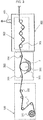
Fig. 1] Fig. 1 is a schematic view showing a process for producing our resin-impregnated fiber bundle. - [
Fig. 2] Fig. 2 is a schematic view showing an example of production process with decompression zone. - [
Fig. 3] Fig. 3 is a schematic view showing another example of production process with decompression zone. - [
Fig. 4] Fig. 4 is a perspective view showing an example of decompression space. - [
Fig. 5] Fig. 5 is a cross sectional view showing the example of decompression space. - [
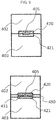
Fig. 6] Fig. 6 is cross sectional view showing another example of decompression space. - [
Fig. 7] Fig. 7 is a front view showing an example of pass-through for fiber bundle on a partition wall of decompression space. - [
Fig. 8] Fig. 8 is a front view showing another example of pass-through for fiber bundle on a partition wall of decompression space. - [
Fig. 9] Fig. 9 is a front view showing another example of pass-through for fiber bundle on a partition wall of decompression space. - [
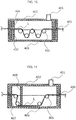
Fig. 10] Fig. 10 is a cross sectional view showing an example with an airtight wall in the decompression space. - [
Fig. 11] Fig. 11 is a cross sectional view showing another example with an airtight wall in the decompression space. - [
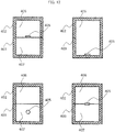
Fig. 12] Fig. 12 is a front view showing an example of pass-through for fiber bundle on the airtight wall. - [
Fig. 13] Fig. 13 is a front view showing another example of pass-through for fiber bundle on the airtight wall. - [
Fig. 14] Fig. 14 is a front view showing another example of pass-through for fiber bundle on the airtight wall. - [
Fig. 15] Fig. 15 is a cross sectional view showing a layout of suction port in the example with the airtight wall in the decompression space. - [
Fig. 16] Fig. 16 is a cross sectional view showing a layout of the fiber bundle pass-through in the example with the airtight wall in the decompression space. - [
Fig. 17] Fig. 17 is a partial enlarged view ofzone 412 inFig. 16 . - [
Fig. 18] Fig. 18 is a schematic view showing a process for producing a roll of our resin-impregnated fiber bundle. - Hereinafter, our invention will be explained in detail.
- With reference to the process shown in
Fig. 1 , our process for producing a resin-impregnated fiber bundle will be explained. The production process comprises unwindingstep 100 to unwind a resin-unimpregnated fiber bundle,resin impregnation step 200 to pass the fiber bundle through an impregnation bath filled with resin, andimpregnation acceleration step 300 to make the resin permeate the fiber bundle. - Unwinding
step 100 comprisesfiber bundle bobbin 101 and unwindingroll 102. - Each production device is provided with suitably selected number of unwinding rolls 102 to lead
fiber bundle 1 which has been unwound fromfiber bundle bobbin 101 toimpregnation step 200 from viewpoints of production facility layout constraint and economic efficiency. The axial direction of unwindingroll 102 should be orthogonal to the travelling direction of fiber bundle, and may be parallel, orthogonal or skew to the axial direction offiber bundle bobbin 101. - A single or plurality kinds of inorganic or organic fiber may be employed as a reinforcing fiber used in the production process. The inorganic fiber may be a glass fiber which is a general reinforcing fiber of FRP fibers while the organic fiber may be carbon fiber or aramid fiber.
-
Impregnation step 200 comprisesimpregnation bath 201 to retainresin 2,introduction roll 203,resin impregnation roll 202 and dischargingroll 204. - According to examples with an impregnation roll shown in figures,
fiber bundle 1 passes throughintroduction roll 203,impregnation roll 202 and dischargingroll 204, and is led to the nextimpregnation acceleration step 300.Impregnation bath 201 is filled withresin 2 so thatimpregnation roll 202 is dipped intoresin 2 to put the resin on the roll. As a result,resin 2 adheres tofiber bundle 1 traveling onimpregnation roll 202 to impregnate the resin into fiber bundle. -
Fig. 1 shows an example in which eachsingle introduction roll 203 and dischargingroll 204 are provided although each plurality of rolls may be provided as roll group. It is preferable that the rotation axes ofintroduction roll 203,impregnation roll 202 and dischargingroll 204 are in parallel to preventfiber bundle 1 from being distorted and folded, although various positional relations of rolls are available. - The above-described impregnation step of impregnation roll type is illustrative only. For example, various alternatives are available such as dip type to dip the fiber bundle directly in the resin and constant discharge type in which the fiber bundle is fed into an impregnation die into which weighed resin is discharged, so that a predetermined amount of resin adheres to and impregnates the fiber bundle.
-
Resin 2 may be a thermosetting resin such as epoxy and unsaturated polyester or a thermoplastic resin such as polyamide, depending on final product usage, usage environment and required specifications, although various alternatives are available. From viewpoints of workability and energy consumption, it is preferable to employ a thermosetting resin such as epoxy resin so that the impregnation step is performed at a low resin temperature. - Although the viscosity of impregnating resin should be lower from a viewpoint of impregnation efficiency, the viscosity should be at a proper level to maintain a predetermined resin content by preventing the resin from dripping before impregnating sufficiently into the fiber bundle. Specifically, the viscosity is preferably 10 to 2,000 mPa·s. It is more preferable that the viscosity is 100 to 1,100 mPa·s.
- It is preferable that
impregnation acceleration step 300 comprises a plurality of impregnation acceleration bars 301 although various alternatives are available. It is preferable thatimpregnation acceleration bar 301 is prevented from rotating around the bar axis. -
Fiber bundle 1 passes through the step zigzag as hooked with impregnation acceleration bars 301. Generally in production process of resin-impregnated fiber bundle, tension is applied tofiber bundle 1 so thatfiber bundle 1 receives thickness-directional reactive force fromimpregnation acceleration bar 301 when passing throughimpregnation acceleration bar 301. The reactive force can accelerate an impregnation (permeation) of fiber bundle withresin 2 adhering tofiber bundle 1 so that voids offiber bundle 1 are filled withresin 2. - It is preferable that
fiber bundle 1 travels at a speed of 0.1 - 300m/min from a viewpoint of productivity. Too high speed might deteriorate the product quality because of insufficient impregnation time. In addition, troubles such as yarn breakage might be caused by insufficient maintenance because the fiber bundle has increased travel resistance and fluffs generated by increased travelling fiber amount per unit time. -
Decompression space 400 characterizing our invention will be explained in detail. The decompression means a pressure reduction below atmospheric pressure of neighboring space. It is preferable that a decompression degree indicated by an inner pressure of the decompression space is 0 to 750 mmHg. It is more preferable that it is vacuum (0mmHg to 76mmHg) so that impregnation is further accelerated. - The zone occupied by
decompression space 400 should includeimpregnation acceleration step 300. As shown inFig. 2 , the decompression space may further includeimpregnation step 200 or further include unwinding step 100 (not illustrated). Alternatively, it may includeimpregnation acceleration step 300 only, as shown inFig. 3 . - Decompression in the step increases the pressure difference between pressure of
resin 2 to impregnate and air pressure remaining infiber bundle 1. As a result, a resin-impregnated fiber bundle has few voids because of accelerated impregnation. Particularly, resinimpregnation acceleration step 300, which greatly contributes to resin impregnation, is performed at a reduced pressure to efficiently improve the impregnation efficiency. - Decompression means to provide
decompression space 400 may be a generally available vacuum pump (not illustrated) to suck out the air throughvacuum suction port 401 in the decompression space as shown inFigs. 2 to 4 although various alternatives are available. - Desirable compression space partition wall to form
decompression 400 characterizing our invention will be explained in detail.Fig. 4 is a perspective view showing an example. -
Decompression space 400 is isolated from the outer space to keep the inner space decompressed bypartition walls partition walls fiber bundle 1 intodecompression space 400 or an exit to discharge the fiber bundle out ofdecompression space 400. At least one ofpartition walls vacuum suction port 401 to provide the decompression space. As shown inFig. 6 ,decompression space 400 should include at least an impregnation acceleration means (corresponding to impregnation acceleration bars 301 in the example). - Materials and the dimensions of
partition walls - To keep the space airtight, it is preferable that a seal structure is provided on a fastening surface to fasten
partition walls Fig. 4 ,partition walls flanges 404 between which a gasket is inserted to fasten them. The number of sectioned partition walls should be fewer like 2-sectioned structure shown inFig. 4 so that airtightness is easily maintained and decompression degree is improved efficiently in the decompression space, although various alternatives are available. - It is preferable to employ a gasket made of an elastic material having an adequate elasticity without harmful effect on products caused by reacting with
resin 2 anddamaging fiber bundle 1 when contactingfiber bundle 1, although various alternatives are available to the extent that the decompression space is kept airtight. The elastic material may be a silicone rubber of adequate elasticity and workability, preferably having a thickness of 0.2 to 10 mm and a hardness of 20 to 90 degrees. - The decompression space partition wall to be easily sectioned can improve in productivity because troubleshooting becomes easy in case of shutdown caused by fibers sticking around
impregnation acceleration bar 301 installed in the decompression space and fluff plugging in fiber bundle pass-through 405. - It is preferable that fiber bundle pass-through 405 has a minimum opening area just enough for
fiber bundle 1 to pass through both entrance and exit as shown inFig. 5 . Further, it is preferable that a zone which doesn't include fiber bundle pass-through 405 is not provided with an opening like the fiber bundle pass-through, as shown inFig. 6 . As a result, the decompression degree indecompression space 400 can be maintained greater because only fiber bundle pass-through 405 communicates with the outer space. - The fiber bundle pass-through 405 may have any shape to the extent of allowing
fiber bundle 1 to pass through. As shown inFig. 7 , it is possible that any one ofpartition walls partition walls Fig. 8 , it is possible that fiber bundle pass-through 405 is formed withelastic material 450 for sealing partition wall introduced for improving airtightness. - As shown in
Fig. 9 , it is possible thatyarn guide members partition walls yarn guide members yarn guide members partition walls elastic material 451 for sealing yarn guide member is inserted betweenyarn guide members yarn guide members partition walls yarn guide members elastic material 450 for sealing partition wall sandwiched thereby. - The same approach as
partition walls yarn guide members yarn guide members elastic material 451 for sealing yarn guide member. - By employing
yarn guide members walls yarn guide members - From a viewpoint of fluff generation prevention, it is important that fiber bundle pass-through 405 and
fiber bundle 1 should be non-contact type. It is preferable that fiber bundle pass-through 405 has 1.2 to 20 times the width and thickness of fiber bundle. Such a minimum opening area can minimize inflow of external air leak through fiber bundle pass-through 405 intodecompression space 400 to enhance airtightness. Also, the airtightness is expected to be further improved by sealing the gap with resin betweenfiber bundle 1 and fiber bundle pass-through 405 becauseresin 2 adhering to fiber bundle inimpregnation step 200 tends to adhere to a boundary part of fiber bundle pass-through 405. - To enhance a decompression degree in the decompression space, it is preferable that a plurality of
airtight walls decompression space 400.Airtight walls partition walls Fig. 10 . Alternatively,airtight wall 406 may be provided as extending frompartition wall 402 only, as shown inFig. 11 . The number of airtight walls is selected freely depending on inner content and desirable decompression degree. - It is preferable that fiber bundle pass-through 405 for fiber bundle to pass through is provided on
airtight walls partition walls fiber bundle 1 to pass through while a zone having no fiber bundle pass-through 405 has no opening to minimize the opening area from a viewpoint of maintaining airtightness. As shown inFig. 12 , the fiber bundle pass-through can be formed by a notch or a hole onairtight wall 406, or alternatively be formed as striding acrossairtight walls Fig. 13 , fiber bundle pass-through 405 may be formed withelastic material 450 for sealing partition wall introduced for improving airtightness. - The same approach can be applied to a configuration inserting
yarn guide materials Fig. 14 , the notch surroundingyarn guide members airtight walls yarn guide members elastic material 450 for sealing partition wall sandwiched thereby. - With
airtight walls - Openings of fiber bundle pass-through 405 provided on
partition walls airtight walls decompression space 400 as starting from the minimum opening area of fiber bundle pass-through 405 provided onpartition walls - When one or more
vacuum suction ports 408 are provided in the airtight wall structure while one or morevacuum suction ports 409 are provided outside the airtight wall structure as shown inFig. 15 , air inflow from outer space can be suppressed effectively to improve decompression degree. - To effectively suppress air inflow from the outer space to improve decompression degree, it is preferable that one or more fiber bundle pass-
throughs 411 are not in a plane formed as including fiber bundle travelling direction and fiber bundle pass-through width direction at the most upstream fiber bundle pass-through 410 among all fiber bundle pass-throughs 405 provided onpartition wall airtight wall yarn guide material Fig. 16 . Such a configuration corresponds to the configuration withdifferent centerlines Fig. 17 as an enlarged view ofzone 412 inFig. 16 . - With such a configuration, it is preferable that contact part is formed in a fiber bundle guide shape to aim to lead the fiber bundle downstream in the process as preventing the fiber bundle from being hooked or damaged, because of unavoidable travelling of
fiber bundle 1 while contacting a part of the fiber bundle pass-through. For example, it is preferable thatairtight walls Fig. 17 , and have an arithmetic average surface roughness Ra of 0.6 to 25. Alternatively, it is possible to provideelastic material 452 for guiding fiber bundle. - Just like
elastic material 450 for sealing partition wall andelastic material 451 for sealing yarn guide described above, it is preferable to employ elastic material for guiding fiber bundle made of an elastic material having an adequate elasticity without harmful effect on products caused by reacting withresin 2 anddamaging fiber bundle 1 when contactingfiber bundle 1. The elastic material may be a silicone rubber of adequate elasticity and workability, preferably having a thickness of 0.2 to 10 mm and a hardness of 20 to 90 degrees. The elastic material may be formed integrally withelastic material 450 for sealing partition wall orelastic material 451 for sealing yarn guide member. - A resin-impregnated fiber bundle produced through our production process can be processed in various ways to make final products. For example, the impregnating resin may further be processed to make semihard to prepare a prepreg to be wound temporarily around a bobbin which can be set to an apparatus for producing a roll of another resin-impregnated fiber bundle to make a final product.
- As shown in
Fig. 18 , a roll of resin-impregnated fiber bundle may be produced in windingstep 500 afterimpregnation acceleration step 300 in the same process. Windingstep 500 comprises: windinghead 501 provided to each mandrel; a plurality of windingrollers 502 provided in the winding head; andmandrel 503 as an object to wind. -
Fiber bundle 1 after passing through resin impregnation acceleration step passes through windingroller 502 fixed on windinghead 501 and is wound up. Windinghead 501 freely moves relative tomandrel 503 rotatable around a shaft fixed in a space according to settings of winding amount and winding angle of fiber bundle designed to meet required specification of roll, so that a roll of resin-impregnated fiber bundle is wound on the mandrel to make a product. - After the winding step, the roll of resin-impregnated fiber bundle passes through a resin curing step and a finishing step including additional processing such as trimming of remnant to make a final product. The curing step may be performed in the same place as winding step without moving, or alternatively, may be performed in a different place shifted from the winding step.
- Our resin-impregnated fiber bundle is widely applicable as materials for fiber reinforced plastic container or the like.
-
- 1: fiber bundle
- 2: resin
- 100: unwinding step
- 101: fiber bundle bobbin
- 102: unwinding roll
- 200: impregnation step
- 201: impregnation bath
- 202: impregnation roll
- 203: introduction roll
- 204: discharging roll
- 300: impregnation acceleration step
- 301: impregnation acceleration bar
- 400: decompression space
- 401: vacuum suction port
- 402:
partition wall 1 - 403:
partition wall 2 - 404: flange
- 405: fiber bundle pass-through
- 406:
airtight wall 1 - 407:
airtight wall 2 - 408:
vacuum suction port 1 - 409:
vacuum suction port 2 - 410: fiber bundle pass-through 1
- 411: fiber bundle pass-through 2
- 412: zone
- 413:
centerline 1 - 414:
centerline 2 - 420:
yarn guide member 1 - 421:
yarn guide member 2 - 450: elastic material for sealing partition wall
- 451:
elastic material 451 for sealing yarn guide member - 452: elastic material for fiber bundle guide
- 500: winding step
- 501: winding head
- 502: winding roller
- 503: mandrel
Claims (15)
- A process for producing a resin-impregnated fiber bundle by continuously impregnating with a resin a fiber bundle continuously travelling, comprising:an unwinding step in which a resin-unimpregnated fiber bundle is unwound;a resin impregnation step in which the fiber bundle is passed into an impregnation bath filled with a resin; andan impregnation acceleration step in which the resin is permeated into the fiber bundle after the resin impregnation step, whereinat least the impregnation acceleration step is performed in a decompression space having a pressure lower than atmospheric pressure,and the decompression space has a pressure lower than a pressure in a space to perform the unwinding step and/or the resin impregnation step.
- The process for producing a resin-impregnated fiber bundle according to claim 1, wherein the decompression space is a vacuum.
- The process for producing a resin-impregnated fiber bundle according to claim 1 or 2, wherein the decompression space comprises two or more partition walls sectioned in a direction approximately orthogonal to a travelling direction of the fiber bundle.
- The process for producing a resin-impregnated fiber bundle according to claim 3, wherein an outer surface of the partition wall is provided with a fiber bundle pass-through to supply and/or discharge the fiber bundle.
- The process for producing a resin-impregnated fiber bundle according to claim 3 or 4, wherein an airtight wall structure having a fiber bundle pass-through for the fiber bundle to pass through is provided in the decompression space.
- The process for producing a resin-impregnated fiber bundle according to claim 5, wherein a fiber bundle pass-through provided on an outer surface of the partition has an opening area equal to or less than an opening area of the fiber bundle pass-through in the airtight wall structure.
- The process for producing a resin-impregnated fiber bundle according to claim 5 or 6, wherein one or more vacuum suction ports are provided in the airtight wall structure while one or more vacuum suction ports are provided outside the airtight wall structure, the vacuum ports being provided on the partition wall.
- The process for producing a resin-impregnated fiber bundle according to any one of claims 5 to 7, wherein one or more of the fiber bundle pass-throughs on the partition wall or the airtight wall are not on a plane formed as including the travelling direction of the fiber bundle and a width direction of the fiber bundle pass-through at the most upstream fiber bundle pass-through.
- The process for producing a resin-impregnated fiber bundle according to any one of claims 5 to 8, wherein a tip of an airtight wall forming the fiber bundle pass-through in the airtight wall structure is formed in a fiber bundle guide shape to aim to lead the fiber bundle downstream by contacting the fiber bundle.
- The process for producing a resin-impregnated fiber bundle according to any one of claims 3 to 9, wherein the fiber bundle pass-through is quadrangular.
- The process for producing a resin-impregnated fiber bundle according to any one of claims 3 to 10, wherein a sheet type elastic member for maintaining airtightness is sandwiched on a contact surface between the sectioned partition walls in the decompression space.
- The process for producing a resin-impregnated fiber bundle according to claim 11, wherein the fiber bundle pass-through is formed with the sheet type elastic member, the partition wall and an airtight wall in the decompression space.
- The process for producing a resin-impregnated fiber bundle according to any one of claims 3 to 12, wherein two or more additional yarn guide members sectioned in the direction approximately orthogonal to the travelling direction of the fiber bundle are sandwiched with a pair of the partition wall and an airtight wall to form the fiber bundle pass-through on the additional yarn guide member in the decompression space.
- The process for producing a resin-impregnated fiber bundle according to any one of claims 1 to 13, wherein the impregnation acceleration step comprises a step of passing the fiber bundle onto an impregnation acceleration bar being prevented from rotating.
- The process for producing a resin-impregnated fiber bundle according to any one of claims 1 to 14, wherein the impregnated fiber bundle is wound with a freely movable winding head onto a mandrel rotating around a fixed shaft to make a roll product after passing through the impregnation acceleration step.
Applications Claiming Priority (2)
| Application Number | Priority Date | Filing Date | Title |
|---|---|---|---|
| JP2015056293 | 2015-03-19 | ||
| PCT/JP2016/056360 WO2016147864A1 (en) | 2015-03-19 | 2016-03-02 | Process for producing resin-impregnated fiber bundle and process for producing roll of resin-impregnated fiber bundle |
Publications (2)
| Publication Number | Publication Date |
|---|---|
| EP3272791A1 true EP3272791A1 (en) | 2018-01-24 |
| EP3272791A4 EP3272791A4 (en) | 2018-11-14 |
Family
ID=56920361
Family Applications (1)
| Application Number | Title | Priority Date | Filing Date |
|---|---|---|---|
| EP16764694.2A Withdrawn EP3272791A4 (en) | 2015-03-19 | 2016-03-02 | Process for producing resin-impregnated fiber bundle and process for producing roll of resin-impregnated fiber bundle |
Country Status (6)
| Country | Link |
|---|---|
| US (1) | US10486338B2 (en) |
| EP (1) | EP3272791A4 (en) |
| JP (1) | JP6735230B2 (en) |
| KR (1) | KR20170126953A (en) |
| CN (1) | CN107428960A (en) |
| WO (1) | WO2016147864A1 (en) |
Cited By (1)
| Publication number | Priority date | Publication date | Assignee | Title |
|---|---|---|---|---|
| WO2020249445A1 (en) * | 2019-06-11 | 2020-12-17 | Covestro Intellectual Property Gmbh & Co. Kg | Pultrusion machine |
Families Citing this family (9)
| Publication number | Priority date | Publication date | Assignee | Title |
|---|---|---|---|---|
| DE102014016023B3 (en) * | 2014-10-29 | 2016-03-24 | Daimler Ag | Compressed gas containers |
| KR101740657B1 (en) | 2016-07-01 | 2017-05-26 | 롯데케미칼 주식회사 | Method for manufacturing long fiber reinforced thermoplastic |
| KR101740658B1 (en) * | 2016-07-04 | 2017-05-26 | 롯데케미칼 주식회사 | Apparatus for manufacturing long fiber reinforced thermoplastic |
| JP7020633B2 (en) * | 2017-02-13 | 2022-02-16 | ニッタ株式会社 | Composite material and prepreg using it |
| CN106827588A (en) * | 2017-03-02 | 2017-06-13 | 江苏奇科技有限公司 | Production line is smeared in the multistage parallel interaction of continuous fiber thermoplastic prepreg |
| CN108099225B (en) * | 2017-12-18 | 2023-10-31 | 金发科技股份有限公司 | Alternating pressure melt impregnation equipment and melt impregnation method |
| JP7243629B2 (en) * | 2018-08-22 | 2023-03-22 | 東レ株式会社 | Prepreg manufacturing method and manufacturing apparatus |
| WO2020136926A1 (en) * | 2018-12-28 | 2020-07-02 | 株式会社Ihiエアロスペース | Frp continuous molding apparatus and frp continuous molding method |
| CN111037951B (en) * | 2019-12-30 | 2022-03-04 | 中国航空制造技术研究院 | Composite material liquid molding injection device and method |
Family Cites Families (13)
| Publication number | Priority date | Publication date | Assignee | Title |
|---|---|---|---|---|
| GB1080562A (en) * | 1964-02-19 | 1967-08-23 | English Electric Co Ltd | Improvements in or relating to reinforced plastics |
| GB1177050A (en) * | 1968-09-23 | 1970-01-07 | Shell Int Research | Method and apparatus for forming an Article from a Resin Impregnated Filament |
| US3649402A (en) * | 1968-09-23 | 1972-03-14 | Shell Oil Co | Method and apparatus for winding resin-impregnated filaments to reduce entrained air |
| JPS5933609B2 (en) | 1976-03-31 | 1984-08-16 | 住友電気工業株式会社 | Method for continuously impregnating fiber bundles with resin |
| JPS5929605B2 (en) | 1976-03-31 | 1984-07-21 | 住友電気工業株式会社 | Method and device for continuously impregnating fiber bundles with resin |
| JPS52117964A (en) | 1976-03-31 | 1977-10-03 | Sumitomo Electric Industries | Equipment for continuously impregnating resin into fiber bundle |
| JPS60240435A (en) | 1984-05-15 | 1985-11-29 | Toyota Motor Corp | Preparation of fiber reinforced resin structure |
| IL80277A0 (en) * | 1985-10-15 | 1987-01-30 | President Eng Corp | Process for the production of prepregs and metal-laminated base material for circuit boards,and apparatus for carrying out this process |
| JPH062349B2 (en) * | 1985-11-25 | 1994-01-12 | 松下電工株式会社 | Process for producing resin-impregnated sheet material and apparatus used for its implementation |
| JP2580906B2 (en) | 1991-10-11 | 1997-02-12 | 日立化成工業株式会社 | Resin impregnation equipment |
| JP2002028924A (en) | 2000-07-17 | 2002-01-29 | Nkk Corp | Resin impregnation method and resin impregnation device |
| JP4149413B2 (en) * | 2004-05-21 | 2008-09-10 | 日信工業株式会社 | Carbon fiber composite material and method for producing the same |
| US20070057404A1 (en) * | 2005-09-12 | 2007-03-15 | Hager William G | Compression and injection molding applications utilizing glass fiber bundles |
-
2016
- 2016-03-02 WO PCT/JP2016/056360 patent/WO2016147864A1/en not_active Ceased
- 2016-03-02 EP EP16764694.2A patent/EP3272791A4/en not_active Withdrawn
- 2016-03-02 CN CN201680011666.4A patent/CN107428960A/en active Pending
- 2016-03-02 KR KR1020177027426A patent/KR20170126953A/en not_active Withdrawn
- 2016-03-02 US US15/559,275 patent/US10486338B2/en not_active Expired - Fee Related
- 2016-03-02 JP JP2016511842A patent/JP6735230B2/en active Active
Cited By (1)
| Publication number | Priority date | Publication date | Assignee | Title |
|---|---|---|---|---|
| WO2020249445A1 (en) * | 2019-06-11 | 2020-12-17 | Covestro Intellectual Property Gmbh & Co. Kg | Pultrusion machine |
Also Published As
| Publication number | Publication date |
|---|---|
| US20180085970A1 (en) | 2018-03-29 |
| JP6735230B2 (en) | 2020-08-05 |
| KR20170126953A (en) | 2017-11-20 |
| EP3272791A4 (en) | 2018-11-14 |
| WO2016147864A1 (en) | 2016-09-22 |
| US10486338B2 (en) | 2019-11-26 |
| JPWO2016147864A1 (en) | 2017-12-28 |
| CN107428960A (en) | 2017-12-01 |
Similar Documents
| Publication | Publication Date | Title |
|---|---|---|
| EP3272791A1 (en) | Process for producing resin-impregnated fiber bundle and process for producing roll of resin-impregnated fiber bundle | |
| KR101787143B1 (en) | Process and apparatus for producing sheet-shaped prepreg | |
| JP7095771B2 (en) | Manufacturing method of fiber reinforced resin molding material | |
| US11492731B2 (en) | Partially separated fiber bundle, production method of partially separated fiber bundle, fiber-reinforced resin molding material using partially separated fiber bundle, and production method of fiber-reinforced resin molding material using partially separated fiber bundle | |
| EP3603917B1 (en) | Production method and coating device for coating-liquid-impregnated sheet-like reinforcing-fiber bundle and sheet-like integrated object | |
| EP3018242B1 (en) | Yarn manufacturing apparatus | |
| CN112533984A (en) | Method for producing prepreg, coating device, and apparatus for producing prepreg | |
| WO2017110912A1 (en) | Fiber-reinforced resin material molding, method for manufacturing fiber-reinforced resin material molding, and method for manufacturing fiber-reinforced resin material | |
| EP3842204A1 (en) | Prepreg manufacturing method and manufacturing apparatus | |
| US20190177888A1 (en) | Partially separated fiber bundle, production method of partially separated fiber bundle, fiber-reinforced resin molding material using partially separated fiber bundle, and production method of fiber-reinforced resin molding material using partially separated fiber bundle | |
| EP3842202B1 (en) | Production method for prepreg, prepreg tape, and fiber reinforced composite material, and prepreg production device | |
| KR101676729B1 (en) | the spreading apparatus and the spreading system of yarn therewith | |
| JP2020028844A (en) | Method for producing reinforced fiber sheet impregnated with coating liquid and sheet-like integrated article, coating apparatus | |
| JP2020028845A (en) | Method for producing reinforced fiber sheet impregnated with coating liquid and sheet-like integrated article, coating apparatus | |
| KR20150121312A (en) | Fiber spreading device for manufacturing system of continuous fiber reinforced composites having the same | |
| CN106044324B (en) | For manufacturing the up- coiler of lap spool and method for winding lap | |
| JP2005325191A (en) | Manufacturing method and manufacturing apparatus for unidirectional prepreg | |
| JP2020029015A (en) | Manufacturing device and manufacturing method for prepreg and sheet-like integrated product | |
| KR102365637B1 (en) | A pultrusion molding apparatus that supplies a carbon fiber fabric using a mat guide on the carbon fiber laminated on the mandrel | |
| JP2025002727A (en) | Manufacturing method of thermoplastic prepreg | |
| ITMI20020394U1 (en) | IRONING AND DEVICE TO PRODUCE A FIBER VEIL | |
| WO2020040151A1 (en) | Method for producing coating-liquid-containing reinforcing fiber tape and coating-liquid-containing reinforcing fiber tape package | |
| JPS63132008A (en) | Method for impregnating fiber-bundle with resin | |
| JP2020029014A (en) | Manufacturing method for prepreg and sheet-like integrated product, and coating device | |
| JP2020028846A (en) | Method for producing reinforced fiber sheet impregnated with coating liquid and sheet-like integrated article, coating apparatus |
Legal Events
| Date | Code | Title | Description |
|---|---|---|---|
| PUAI | Public reference made under article 153(3) epc to a published international application that has entered the european phase |
Free format text: ORIGINAL CODE: 0009012 |
|
| 17P | Request for examination filed |
Effective date: 20170913 |
|
| AK | Designated contracting states |
Kind code of ref document: A1 Designated state(s): AL AT BE BG CH CY CZ DE DK EE ES FI FR GB GR HR HU IE IS IT LI LT LU LV MC MK MT NL NO PL PT RO RS SE SI SK SM TR |
|
| AX | Request for extension of the european patent |
Extension state: BA ME |
|
| DAV | Request for validation of the european patent (deleted) | ||
| DAX | Request for extension of the european patent (deleted) | ||
| A4 | Supplementary search report drawn up and despatched |
Effective date: 20181012 |
|
| RIC1 | Information provided on ipc code assigned before grant |
Ipc: B29B 15/12 20060101AFI20181008BHEP Ipc: B29K 105/08 20060101ALN20181008BHEP |
|
| STAA | Information on the status of an ep patent application or granted ep patent |
Free format text: STATUS: THE APPLICATION HAS BEEN WITHDRAWN |
|
| 18W | Application withdrawn |
Effective date: 20200907 |
|
| RIC1 | Information provided on ipc code assigned before grant |
Ipc: B29B 15/12 20060101AFI20200907BHEP Ipc: B29K 105/08 20060101ALN20200907BHEP |